

Page 1
MC ALTERNATOR
DIAGNOSTIC REPAIR MANUAL
ISSUED JANUARY 1979
P.0, BOX 8, WAUKESHA. WISCONSIN 53186
PRINTED IN U.S.A.
51834
Page 2

This Repair Manual is provided to aid the technician in the
analysis and repair of malfunctions that might occur in the
MC alternator or its engine. Keep the Manual in a safe place
and refer to it whenever necessary.
All information, illustrations and specifications contained
in this Manual are based on the latest product information
available at the time of publication. Generac reserves the
right to make changes in any product at any time without no
tice.
GENERAC
P.O.BOX 8
WAUKESHA. WISCONSIN 53186
Page 3

PART I
GENERAL
Section 1.1
1.1.1
1.1.2
1.1.3
1.1.4
• 1.1.5
1.1.6
Section 1.2
Section 1.3
SPECIFICATIONS
Model Numbers
Fuels and Oils
Torque Specifications (General)
Torque Specifications (Special)
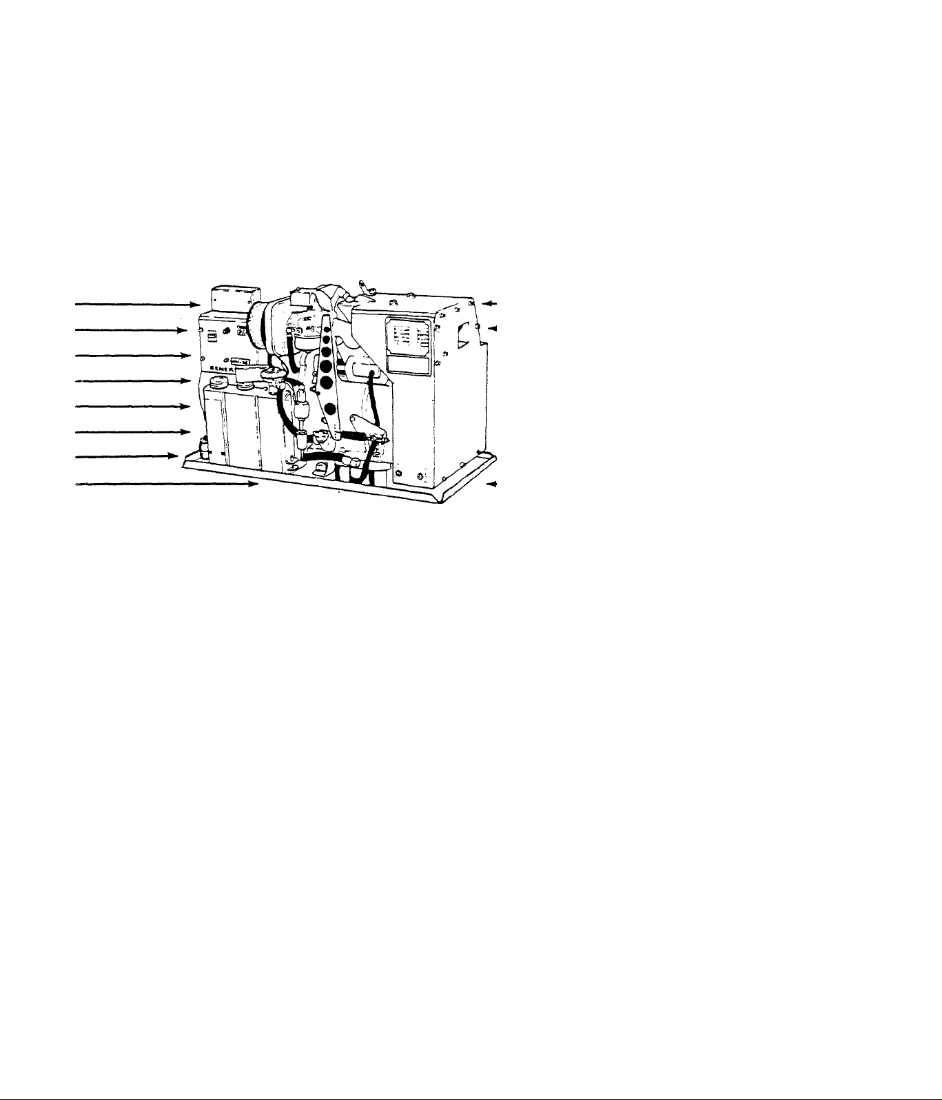
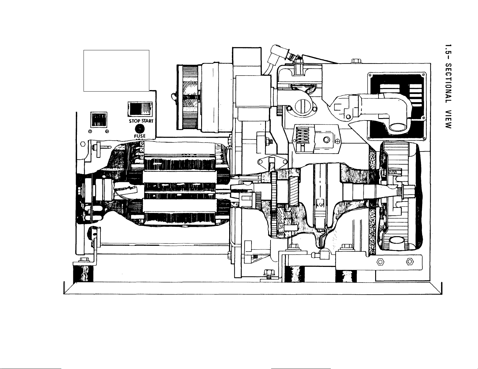
Sectional View
Engine Specifications
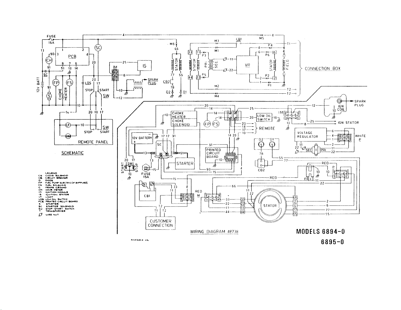
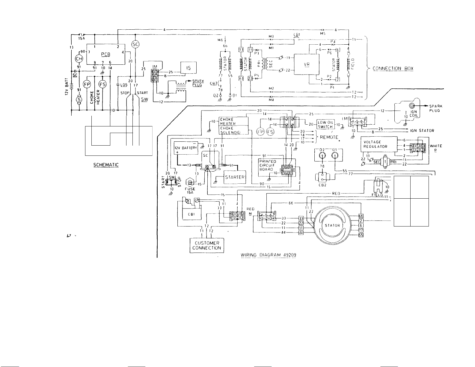
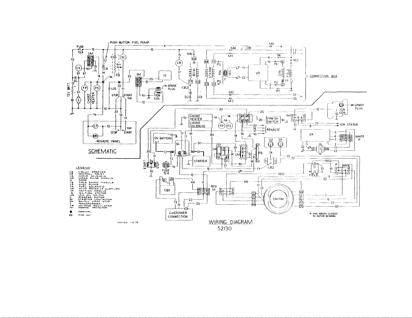
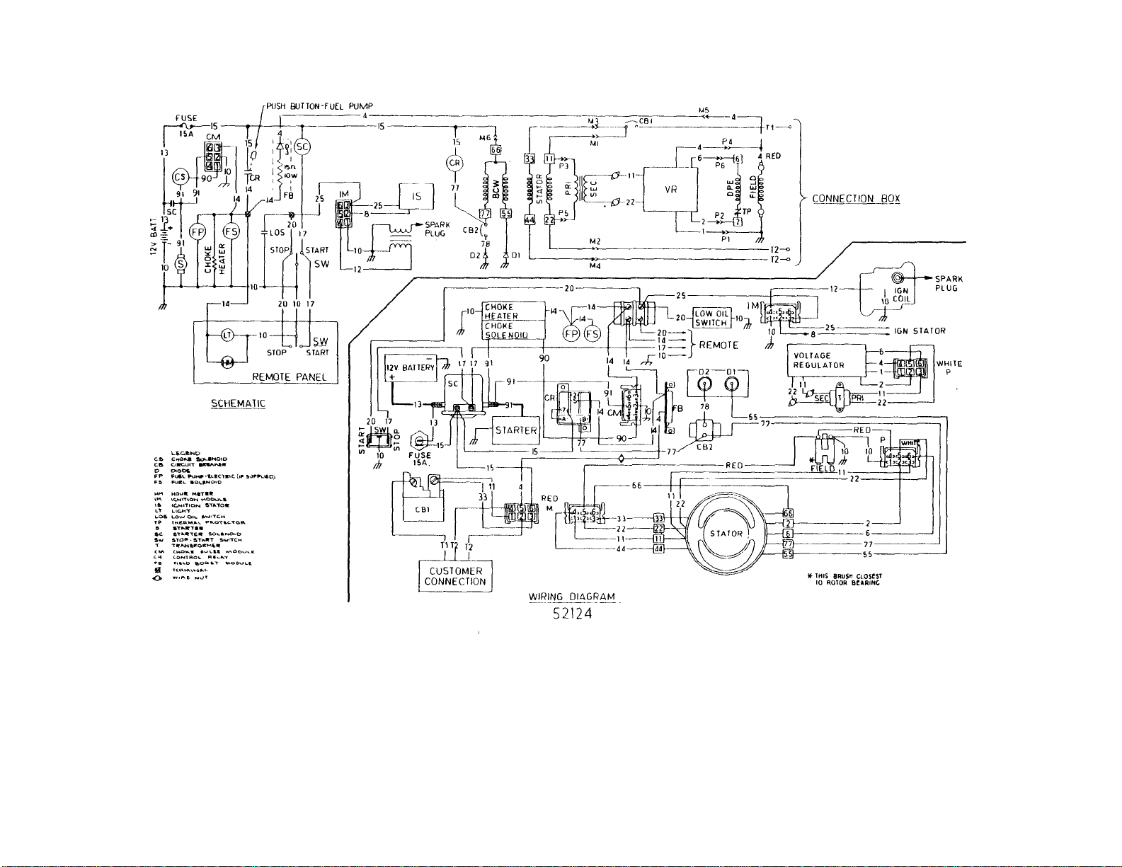
WIRING DIAGRAMS
SPECIAL TOOLS
Page 4
SPECIFICATIONS
1.1.T-M0DEL NUMBERS
SECTION 1.1
Model No,
Wattage Capacitv
Voltage
MC-35
6894
3500 3500 3800
120* 120* 120*
Maximum Amperes 29,2 at 120 V, 31,7 at 120 V.
Phase 1-Phase 1 1-Phase 1-Phase 1-Phase
Frequency
Voltage
Regulation
Solid state voltage regulator maintains 120 Volts AC
(±27o) at 60 Hertz
MC-35
6895
MC-38
6938
MC-38
69 39
MC-40
6896
3800 4000
120* 120*
33.3 at 120 V.
1 -Phasel_1-Phase
60 Hertz at 3600 rpm
Batterv Charge 0-10 Amperes at 12 Volts DC
Gross Weight
(wet)
Engine Part No,
Bore
Stroke
Displacement
48078 48078
Approximately 127 pounds
48078 48078 48078
78 mm
62 mm
296 cc
Governed Speed 3720 rpm at no-load
Ignition System
Starting System
Cranking Current
Average Fuel
Consumption
Type of Fuel
Pump
Mech,
12 Volt DC electric (Ring Gear)
Approximately 0,70 Gallons per Hour
Elec, Mech,
Solid State
Approximately 90 Amperes
Elec, Mech, ■ Elec,
MC-40
6897 ..
4000
120*
48078
'Factory connected for 120 Volt AC output only. Unit is reconnectable
to provide dual voltage output.
1.1.2-FUELS AND OILS
RECOMMENDED FUEL
Use NON-LEADED gasoline. Leaded REGULAR grade gasoline is an acceptab
le substitute. Do not use any highly leaded, premium gasoline,
RECOMMENDED OIL
I
Use oil classified ”For Service SC,
SD or SE”, as shown in the CHART at
USE OIL CLASSIFIED "FOR SERVICE SC, SD, or SE"
---------------------------------------
USE SAE 10 W
Of 10W-30OIL
^-----------------------------
USE SAE 30 OIL
USE SAE 20 W
or 10W-30 OIL
right.
-10“F. 10“F. 32'F.
■22^C. •12.2'^C. O'C.
TEMFERATURE RANGE ANTICIPATED BEFORE NEXT OIL CHANGE
1,1-1
Page 5

1.1.3- TORQUE SPECIFICATIONS (GENERAL)
STANDARD TORQUE VALUES
Grade 2
BOLT SIZE
1/4-20
1/4-28
5/16-18
5/16-24
3/8-16
3/8-24
7/16-14
7/16-20
1/2-13
1/2-20
9/16-12
9/16-18
5/8-11 92
5/8-18 105
3/4-10
3/4-16 180 140
7/8-9
7/8-14
1-8 300
1-14
DRY LUB
5
6
11
13 10
20
23 17
32
36 27
49
55
70
78
165 125
200
225
340 260
15
25
38
42 85
54 110
60
71
81
155
170
230
All Values in FOOT-POUNDS
DRY
4
5 10
8 17
19
31 24
35
49
55 42
75
120
150
170
270
295 230
395
435
590
680
Grade 5
LUB
8
13 21
15
27
38
58
65
84
93
115
130
205
305
335
455
5.10
DRY LUB
6 10
7
12
24
38 29
43
61 47
68
93 72
105
135
150
185
210
330
365
530'
585 450
795 610
Grade 7
16 24
18
33
52
80
105
115
145
160
250
280 420
405
DRY LUB
8
9 14
12
27
44 34
49
70 54
78
105
120 90
155 120
170
210
240
375 290
605 455
670
905 695
Grade 8
9
11
18
21
38
60
82
132
165
185
320
515
GRADE
BOLT HEAD
SYMBOL
o
1.1.4- TORQUE SPECIFICATIONS (SPECIAL)
Spark Plug
Cylinder Head Bolts
Connecting Rod Cap Bolts
Engine Gear Cover Bolts
Blower Fan (Special M14 Hex Nut)
Rotor Bolt
Mechanical Fuel Pump Bolts
INCH-POUNDS FOOT-POUNDS
216-264
264-348
216-264
90-110
600-660 50-55
180-200
25-30
18-22
22-29
18-22
7.5-9
15-17
1.1-2
Page 6
г=
ID
о о
о о
^ BREAKER ^
—
о
—J
U)
I
Page 7

1.1.6-ENGINE SPECIFICATIONS
INCHES METRIC
Spark Plug Gap
Valve Spring Length
Valve Spring Compression Length
Valve Seat Width
Valve Tappet Clearance
Crankshaft End Play
Piston Diameter (at skirt)
Piston Pin Diameter
Width of Compression Grooves
Width of Oil Ring Groove
Width of Compression Rings
0.035
0.009 mm
1.2995 33.000 mm
1.0236
0.039-
26.000 mm
1-2 mm
0.079
0.0039-
0.1-0.2 mm
0.0078
0.0039-
0.1-0.3 mm
0.0118
3.067-
3.068
0.7080-
0.7086
0.0797-
0.0805
0.1584-
0.1593
0.0775-
0.0784
77.91-
77.93 mm
17.989 mm-
18.000 mm
2.025 mm-
2.045 ram
4.025 mm-
4.045 mm
1.970 mm-
1.990 mm
Width of Oil Ring
Ring End Gap
Maximum Permissible Out-of-Roundness
of Crankpin
Connecting Rod to Crankpin Clearance
Valve Spring Force
0.1560-
0.1570
0.0078-
0.0157
3.970 mm-
3.990 mm
0.2 - 0.4
mm
0.002 0.05 mm
0.001-
0.002
14.81-
19.76 lbs
0.030-
0.050 mm
kilograms
6.72-8.96
1.1-4
Page 8
K>
I
6896- 0
6897- 0
co
гп
о
g i
>r
Isa
CD
XI
>
CD
Page 9
N5
ro
FUSE-
m
—14
--
@—
iTt>
L&ceND
C6 ChO«.B SOvKNOlO
c& c>*cutT BrmAiKClt
O OiOOB
FP FoCL Pur^-ei.CCTRlC(ir »OPPl^tfcO^
F& FuBc BOwBnO'D
C FKikHt C«OUNO
>4M hOU« MtT«H
IM iCNiTlOM N\OOOUt
vS STikTO«
l-T CICMT
LOW OlC BW>TCm
»cm p«iNTto Cimcj'T mo*^«o
s m-TK«!««
sc «Tk.«Te<« &OLBNo>o
Sw BTOP-ST^RT Switch
i^imi tmut
-----
1
REMOTE PANEL
STO
0 1
7
0 1
2
o—
—o
c
TART
p
tu
----
1
1 e
ffh
-2
------
6
MODELS 6894-1,-2
6895- 1,-2
6896- 1,-2
6897- 1,-2,-3
6938- 0
6939- 0
Page 10
ю
I
со
о
о
оо
to
о
со
Page 11
N>
i
4ï^
О
О
05
ОО
СО
I
Page 12
RED CONNECTOR PLUG
0
RED RECEPTACLE
oKslCel
CjlLjlCa
11 '—
T1
120
V.
CUSTOMERS
CONNECTIONS
FACTORY WIRING CONNECTIONS
120 VOLTS ONLY
1
44
22
V
120VT 120V.
•—4*—>
-240V, -
CUSTOMER
CONNECTIONS
-CD □ d]
j
-----
-L
[4] rs: Cel
RED CONNECTOR
PLUG
RED
RECEPTACLE
N
RECONNECTED FOR
120/240 VOLT
OUTPUT
1.2-5
Page 13
SECTION 1.3
SPECIAL TOOLS
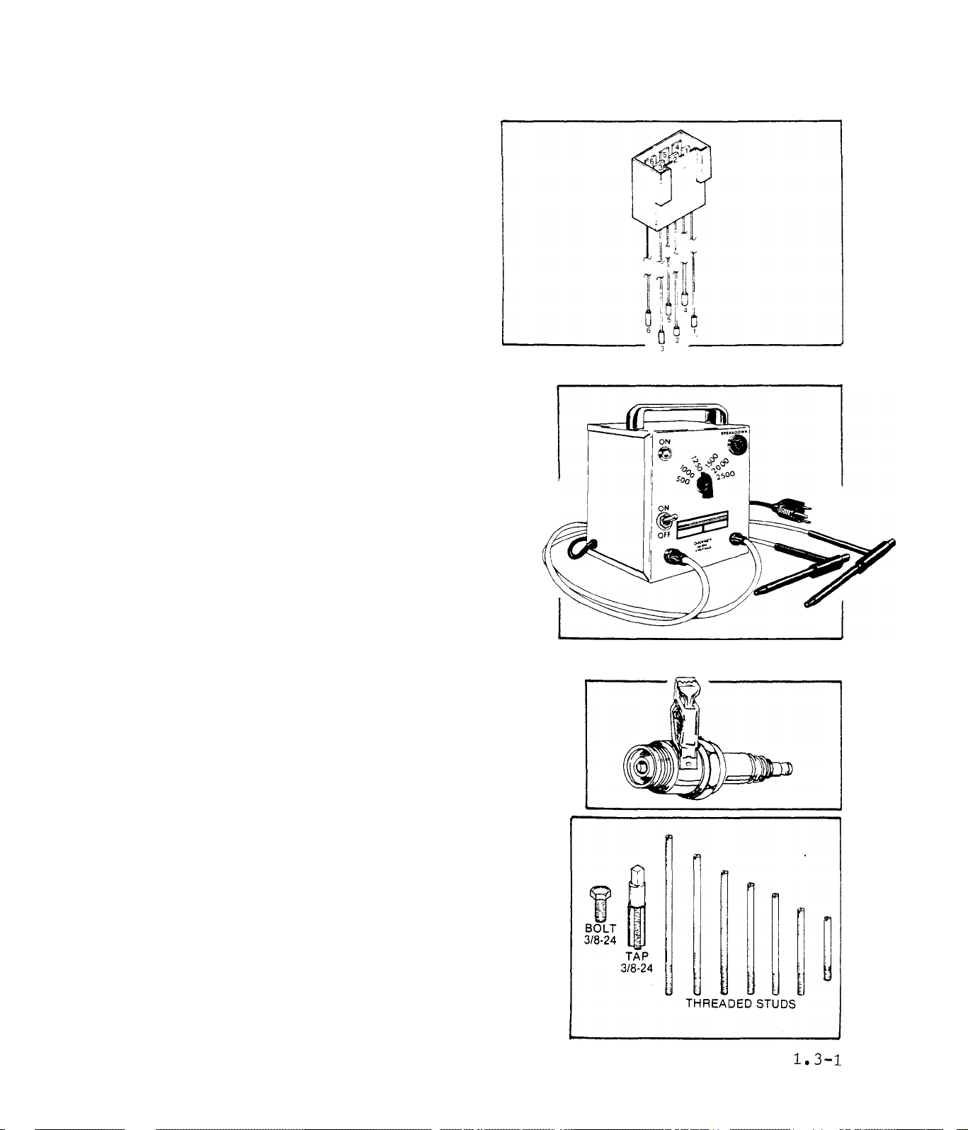
ELEHTRICAL TEST PLUG
The Electrical Test Plug facilit
ates the testing of electrical
components in circuits that pass
through the red and white stator
can receptacles, or through the
Ignition Module receptacle. Use
the Test Plug in any diagnostic
test that calls for connection of
the VOM test probes to pins in
these receptacles. Order Part No.
27069.
INSULATION BREAKDOWN TESTER
Resistance testing of alternator compon
ents with an Ohmmeter is generally valid.
Such resistance tests will nearly always
indicate the presence of an open or shor
ted condition. However, some malfunctions
do not become evident until an electrical
load is applied across the defective'com
ponent. The insulation breakdown tester
permits a component to be tested under a
simulated load condition, by applying a
selected voltage to the component. Follow
the tester manufacturer’s instructions
strictly when using the tester.
SPARK T.ESTER
The Spark Tester is used to check for pro
per ignition spark with the engine cranking.
Order Part' No. 41503.
ROTOR REMOVAL KIT
The Rotor Removal Kit consists of a 3/8-24
TAP, 3/8-24 BOLT, and threaded studs o'f
varying lengths. The kit is used for remo
val of the rotor. Order Part No. 41079.
Page 14
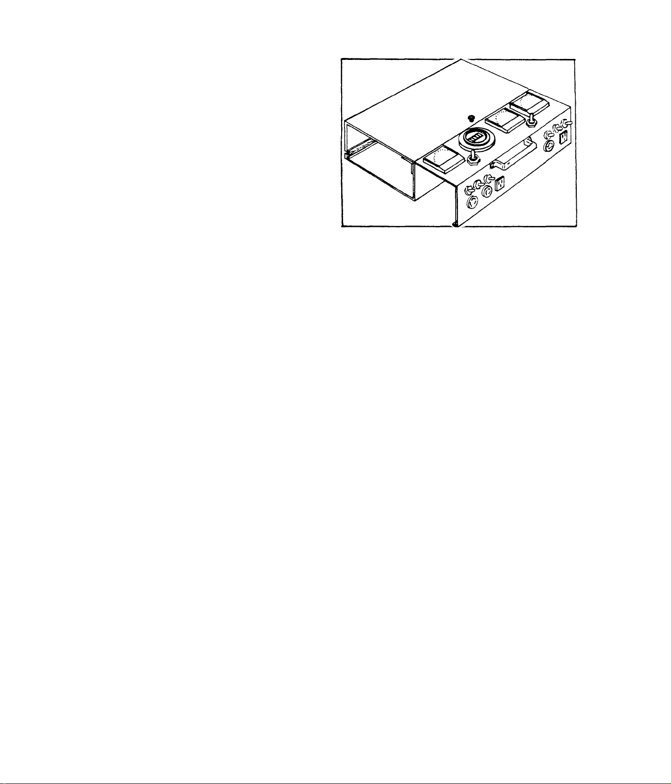
LOAD BANK
The Load Bank is used to apply an
electrical load to alternators..
The unit is equipped with a Volt
meter, Ammmeter and Frequency Me
ter, as well as the necessary
switches for selecting the desir
ed load. Specify Model No. 5515,
1.3-2
Page 15

PART II
TROUBLE DIAGNOSIS
Section 2.1
2.1.1
Section 2.2
Section 2,3
- DIAGNOSTIC FLOW CHARTS
- Introduction
Engine won’t Crank
Engine Cranks, won’t Start
Engine starts hard - Runs Rough
Switch set to STOP - Engine Keeps Running
AC Voltage Low
AC Power Low
AC Voltage High
No AC Voltage
- Diagnostic Tests
- Battery Charge Circuit Tests
Page 16
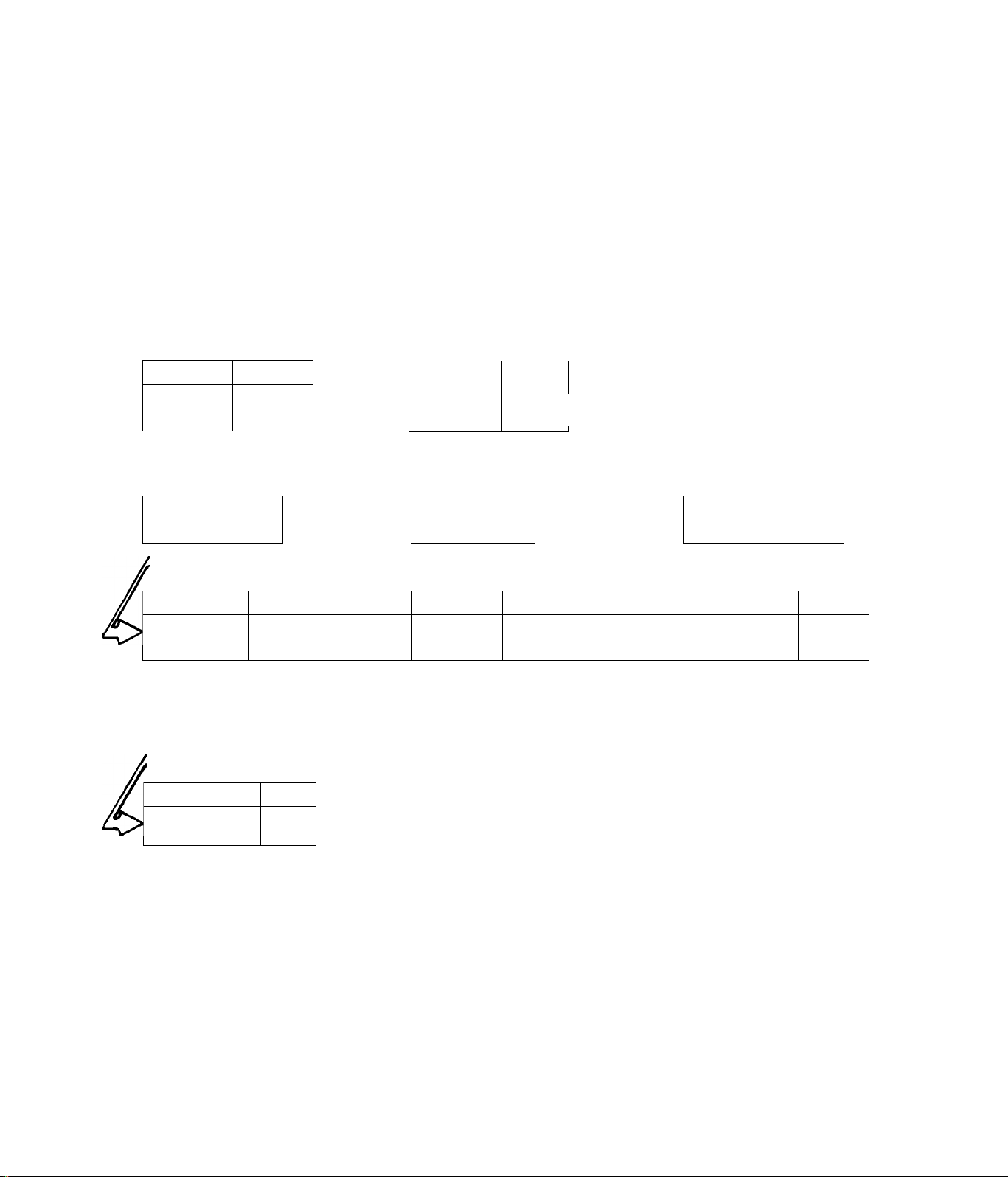
SECTION 2.1
DIAGNOSTIC FLOW CHARTS
2.1.1-INTROUUCTION
The DIAGNOSTIC FLOW CHARTS that follow are intended for use with the
DIAGNOSTIC TESTS in Section 2.2, Test numbers assigned in the FLOW
CHART are identical to the numbers assigned to specific tests in Sec
tion 2.2.
ENGINE WON’T CRANK
TEST 1
15 Amp
Page
2.2-1
Fuse
BAD
Replace Rise
TEST 4
Starter
Solenoid
I i
|Repl
TEST 7
Page 1
2.2-2|iGOODZ^
ace
Page]
Starter
Ring Gear
______
BAD
9 0/,
1
“GOODI^
'GOOD
1
TEST 2 Page
Battery
9.2-1*—GOOD--^ Start/Stop
2.2-1
BAD
<>
Recharge or
Replace
;GOOD
TEST 5
Starter
Motor
L___1
--------1
Replace
ENGINE
SEIZED
Page 1
2.2-3 |—■ GOODI^
GOOD
7F1
idJ
ll
BAD
TEST 3
Cr-r,- i-^U
Switch
~1 r
Page
2.2-2
BAD
Replace Switch
TEST 6 Page
Starter
Drive Gear
2.2-4
Replace
n
Replace
0
Repair
or
Replace
Page 17
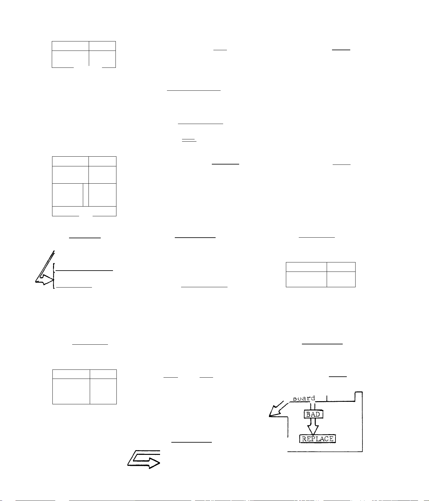
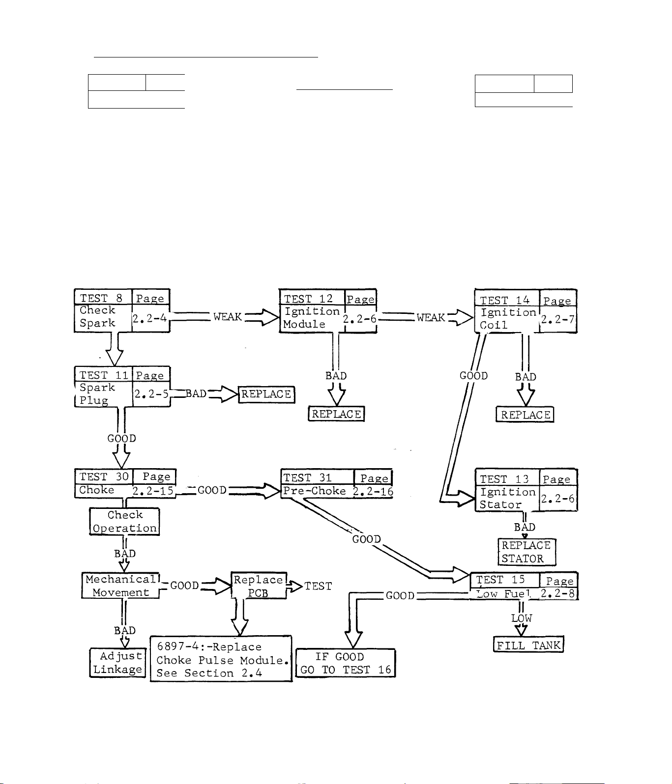
ENGINE CRANKS, WON’T START
TEST 8
Check
Spark
Page
2.2-^’
If
IF SPARK CHECKS GOOD
GO TO TEST 15
TEST 11
Spark
Plug
Page
2.2-5
BAD
TEST 9
________ _______
OIL LEVEL LOW |
iz
IFILL TANK
........-nnnn-
TEST 12
Ignition
Module
IbadI
Page
Page I
2.2-6 ^GOOD =CH
TEST 10
Low Oil
Switch
ba:
REPAIR/REPLACE
TEST 13
Ignition
Stator
IBAD
Page
2.2-5
D
Page
2.2-6
n
n
Replace
TEST 14 Page
Ignition *2 2-7
Coil I * I
I
I REPLACE
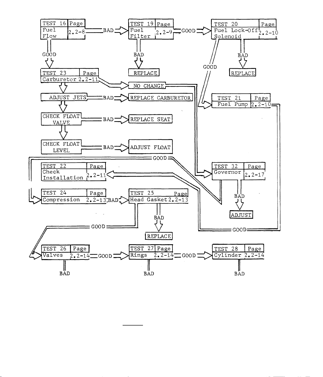
TEST 16
No Fuel
Flow
Page
2.2-8
|Replace|
IF SPARK CHECKS GOOD I
O
TEST 17
4 Amp
.BAD Fuse
;GOOD:
GO TO TEST 15
:G00D:
Page
2.2-8
r
:good:
5
¡Replace
TEST 15
Low Fuel
LOW
FILL TANK
TEST 18
Printed
Circuit
Page
2.2-8
Page
2.2-9
GO TO TEST
23
2.1-2
BAD
Except 6897-4
See Section 2.4
IREFIACEI
;G00D;
GO TO TEST 19
Page 18

TEST 19
Fuel
Filter
Page
2.2-9
IGOOD;
TEST 20
Fuel
Lock-Off ;
Solenoid
Page
L2-10
____
TEST 21
Fuel
Pump |2.2-lC
1
Page
bad!
REPLACE
TEST 22 Page
Check
Installation_
IF FUEL FLOW IS GOOD
GO TO TEST 23
--------------------
2.2-11
2
ADJUST
JETS
test:! BAD
1 .
D
BA
T
REPLACE
:GOOD:
TEST 23 Pagel
Carburetor 2.2-11”^^^
u
REPLACE
CARBURETOR
CHANG E¡f>
TEST
BAD
2
REPLACE
TEST 24 Page
L
Compression!.2-13
GOOD
ICO TO TEST 29
Iz
CHECK
FLOAT Z^BAD^Z^^
SEAT
0
CHECK 1
FLOAT ::;>bad;i::>
LEVEL
REPLACE
SEAT
ADJUST
KLOAT i
LEVEL
GO TO TEST 27
TEST
;BAD
TEST 25 page! ^
Vi n A J _ I
Head
Gasket^
_____
| o
Iz
BAD
2
REPLACE
GASKET
5
Itest
TEST 26| Page
Valves 2.2-14
iz
REPAIR
I
[TEST
2.1-3
Page 19
IF COMPRESSION IS GOOD, GO TO TEST 29r
TEST 27
Rings 2
.. 1 i ’
BAD
V
REPIACE
17
TEST
Page
-.2-14
■good:
TEST 28 Page
Cylinder 2.2-14
\ I I ‘ *
BAD
REPAIR
TEST 29
77
TEST
ENGINE STARTS HARD - RUNS ROUGH
Timing
Page
Z.2-14
2.1-4
Page 20
A
REPAIR
REPLACE
SWITCH SET TO STOP - ENGINE KEEPS RUNNING
TEST 3 jPagej
Replace Switch
REPAIR
2.1-5
Page 21
A-C VOLTAGE LOW
TEST 33
Check
Frequency
B/1Id
TEST 32
Governor
Bi
<
2.2-17
____
2.2-17
L
Page
:good
i
Page
A-C POWER LOW
2*1-6
Page 22
A-C VOLTAGE HIGH
TEST 36
Check
Output ;
Voltage
TEST 36
Check
Output
Voltage
Page
>.2-19
____
Page
^2-19
ZZBAD
1
CHECK CUSTOMER WIRING|<r^IZZZ.GOOD
NO A-C VOLTAGE
TEST 38
Main
Circuit .
Breaker
Page
^2-20
____
1
:good:
TEST 37
Sensing
Transformer
BAD
Replace
Transformer
TEST
TEST 39
check Rotor2 2-20“
j Paee
12.2-19
J_____
Pag£
GOOD
<>
Check Customer
____
Wiring
TEST
TEST 40
Check Field
Boost
Check Wire ^^0-
No. 14
____
Page
2.2-21lC>
BAD
iZ
REPLACE
TEST
CHECK VOLTAGE* _
TO ROTOR I
\ t
BAD
0
Jcheck No. 4 Wire
1 for 12 Volts
^~li
GOOD
BAD
¡REPLACE
¡TEST
IGOOD
testIcT^
,
________Iz__________
.•Replace Printed
"[Circuit Board
■ 2.1-7
Page 23

SECTION 2.2
DIAGNOSTIC TESTS
TEST 1-15 AMPFUSE
Remove and visually inspect the 15
Amp Fuse. Replace, if Fuse element
has melted. A more thorough check
may be made with a Volt-Ohm-Milli-
ammeter, as follows
1. )-Set VOM to ”+DC” and to "Rxl”
scale.
2. )-Connect meter test probes and
”Zero’^ the meter.
3. )-Connect meter test probes to
Fuse ends. Meter needle should
swing upscale to ’^0” ohms (continu
ity). If meter needle does not move
upscale, replace the Fuse.
RESULTS:-Fuse tests bad
Fuse tests good
TEST 2-BATTERY
Check Battery condition, as well as
the condition, cleanliness and sec
urity of battery cables and connec
tions .
RESULTS:-Battery, cables or connections,
check bad
Battery, cables or connections,
check good
............
.......
.
.Install new 15 Amp Fuse
.Continue tests
.Recharge or replace de
fective Battery. Repair,
clean or replace defect
ive cables or connection
.Continue tests
2.2-1
Page 24
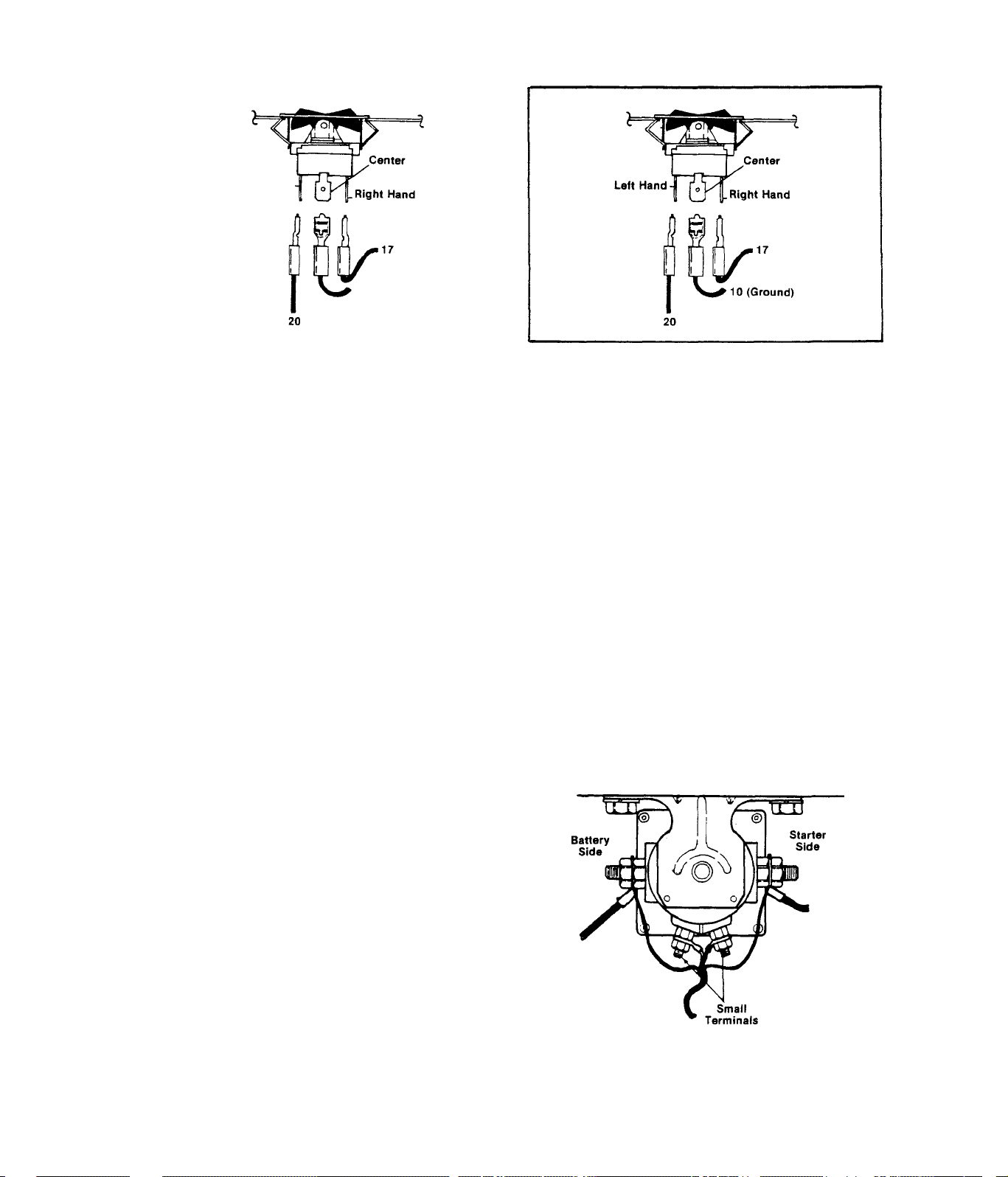
TEST3-ST0P/START SWITCH
Left Hand
10 (Ground)
Remove 15 Amp Fuse to disconnect
starting circuit. Remove panel
top cover. Disconnect wires from
switch terminals to prevent int
eraction. Set VOM to "+DC” and to
"Rxl” scale, then zero the meter.
Connect meter test probes to the
switch center and right hand ter
minals (as viewed from switch
rear). Meter needle should not
TT,^-<rQ H QT.ri rph at START - meter
Connect VOM test probes to Switch
center and left terminals (as vi
ewed from switch rear). Hold the
Switch at START - meter needle
should not move. Release the Switch
to NEUTRAL - meter needle should
not move. Hold the Switch at STOP needle should swing upscale to ”0",
.Install new Stop/Start Switch
.Connect Switch wires, install
top panel and 15 Amp Fuse,
Continue tests.
A.)- Set Stop/Start Switch to START
and back to NEUTRAL several times.
An audible ’’click" should be heard
as the solenoid actuates.
2.2-2
Page 25
RESULTS:- Solenoid actuates, engine
does not crank
...............
Continue tests in Paragraph B
Solenoid does not actuate.•...Continue tests in Paragraph D
B. )- Set VOM to ”+DC” and to a scale greater than 12 Volts DC. Connect
the NEGATIVE (COMMON) test probe to ground. Connect the POSITIVE (+)
probe to the battery cable connection on the solenoid. Meter should in
dicate approximately 12 Volts DC.
RESULTS: - Meter reads 12 Volts DC
Meter reads less than 12
.....
....
Continue tests in Paragraph C
.Check for open or shorted wire
Volts DC (or loose connection) between
Battery and Starter Solenoid
C. )- Connect POSITIVE (+)'meter test probe to starter cable connection
on solenoid. Connect NEGATIVE (COMMON) probe to ground. Hold Stop/Start
Switch at START - meter should indicate approximately 12 Volts DC.
RESULTS:- Meter does not read
12 Volts DC.....
Meter reads 12 Volts and
..........
.....
...Install new Starter Solenoid
Continue tests in DIAGNOSTIC
Solenoid checks good FLOW CHARTS
D. )- Set VOM to ”+DC” and to a scale greater than 12 Volts. Connect the
meter POSITIVE (+) test probe to one of the small terminals on the sol
enoid. Connect the remaining probe to ground. Meter needle should read
approximately 12 Volts DC. With one probe'still connected to ground,
connect the remaining terminal to the other small terminal on the solen
oid - meter should indicate approximately 12 Volts DC.
RESULTS:- Meter indicates 12 Volts......Continue tests
Meter does NOT read 12 Volts..Repeat Tests 1, 2 and 3. When
sure that these tests are good
and 12 Volts is not indicated
in Test 4.D., replace solenoid
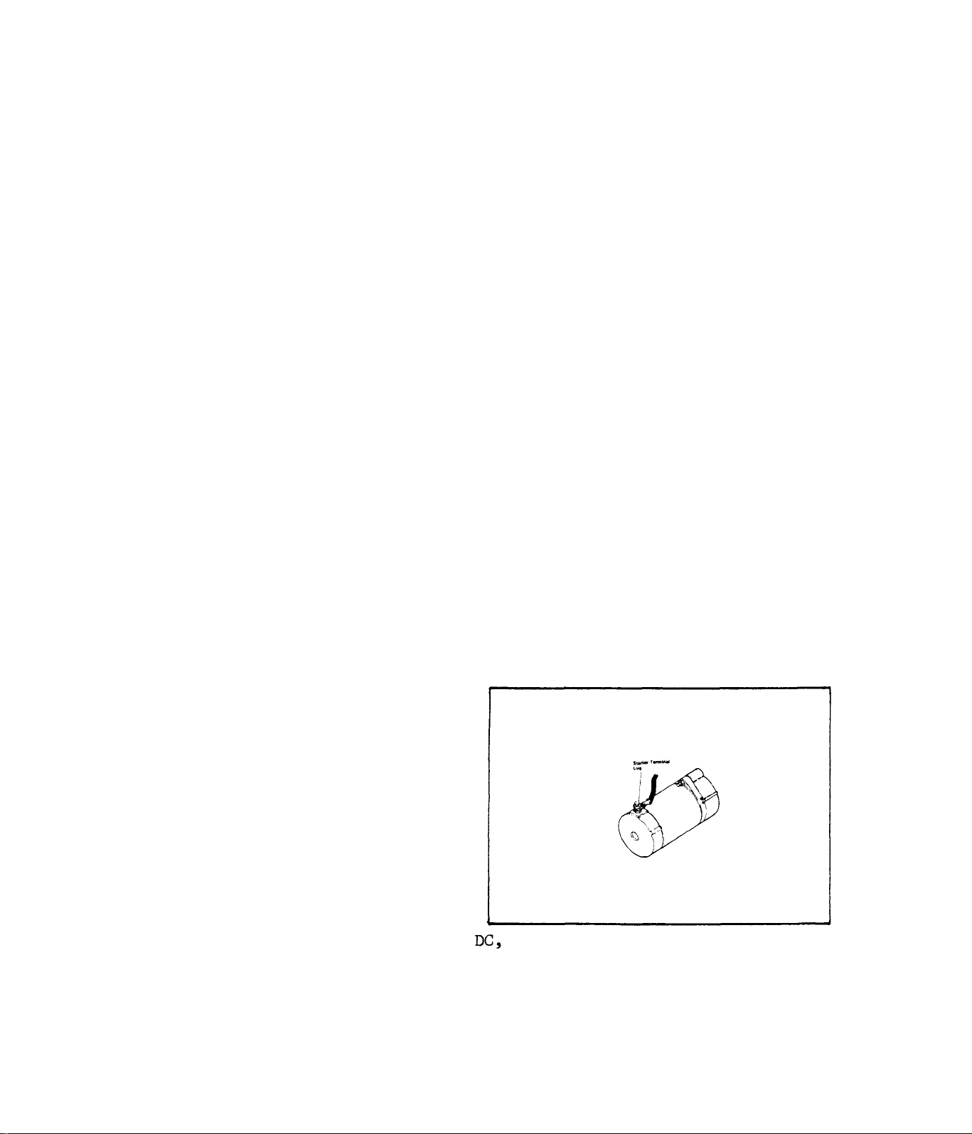
TEST 5-STARTER MOTOR
Set VOM to ”-hDC” and to a scale
greater than 12 Volts DC. Conn
ect VOM positive (4-) test probe
to the Starter terminal lug and
COMMON (-) test probe to frame
ground. Hold Stop/Start switch
at START. Meter should indicate
approximately 12 Volts DC and
starter motor should run.
Starter runs.................................Continue tests
Meter indicates 12 Volts DC,
Starter does not run
.......................
Meter does not indicate 12 Volts
........
Replace Starter
Check Starter cable
2.2-3
Page 26
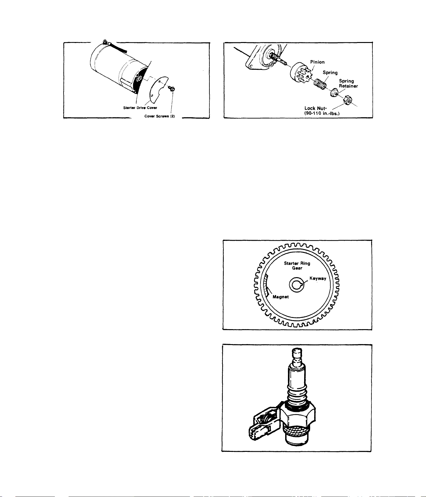
TEST 6-STARTER DRIVE GEAR
A.)-Hold Stop/Start switch at its
START position and listen for the
starter motor. If motor runs free
B,)-Visually check Starter pinion
for damage, if damaged, replace
pinion.
ly (without load), remove Starter
drive cover.
C,)-To replace Starter pinion assembly, remove lock nut, spring retain
er, and pinion. Install a new pinion, spring, spring retainer and lock
nut. Tighten lock nut to 90-110 inch-pounds, DO NOT LUBRICATE PINION
SPLINES,
RESULTS:- Starter drive checks good
Starter drive is defective.,,,,,,,.................
.................
.Continue tests
Replace
TEST 7-STARTER RING GEAR
Inspect Starter Ring Gear for dam
age, Ring Gear and Fly^dieel are
heat shrunk onto Rotor aaaembly.
If replacement is necessary, ent
ire assembly must be replaced.
TEST 8-CHECK SPARK
Disconnect spark plug lead from
engine spark plug and connect to
Spark Tester (Part No, 41503).
Connect Tester clamp to engine
spark plug. Crank engine - spark
tester should emit a blue, snappy
spark.
RESULTS:- Spark tests good...
.
.......
...Go to Test 15
Spark tests bad,
......
2.2-4
Continue tests
.....
........
Page 27
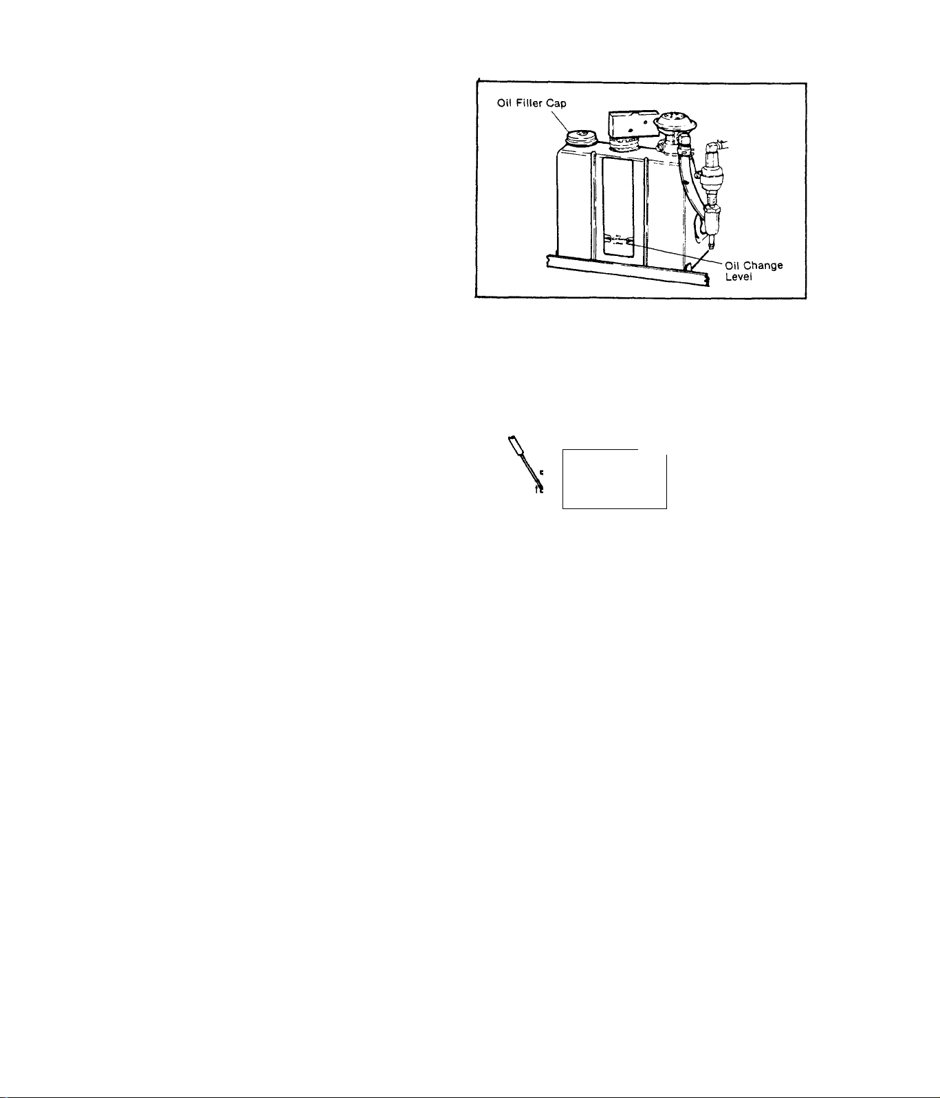
TEST 9-OIL MAKE-UP TANK
Check oil level in Oil Make-Up
Tank. If oil level is below OIL
CHANGE LEVEL arrows, fill tank
with recommended engine oil and
recheck for proper start.
TEST 10-LOW OIL SWITCH
Remove Low Oil Switch Cover and
slide it down the Switch wires
to expose the Switch terminals.
Set VOM to "+DC" and to "Rxl"
scale, then zero the meter. Con
nect one meter test probe to the
lower terminal on side of switch.
Connect remaining test probe to
ground terminal on bottom of the
switch. Move switch actuating le
ver DOWN (simulated low oil cond
ition) - meter needle should
swing upscale to ”0”. Raise the
switch actuating lever (FULL con
dition) - meter needle should
drop downscale to infinity.
Oo
LOW OIL
SWITCH'
TEST PROBES
mr^
ooj
A
METER
READS
INFINITY
METER
READS
V
•0"
RESULTS:- Switch tests bad..
Switch tests good.
A
CAUTION
.Replace switch
.Continue tests
When reassembling Switch cover, make sure float arm is in place
on top of switch actuating lever, or switch will not function.
TEST 11-SPARK PLUG
Remove engine spark plug. With spark plug lead connected to plug, ground
the spark plug against the engine block and crank engine. Spark plug
should emit a sharp, snappy, blue spark,
RESULTS;- Spark Plug bests bad..,....................Replace Spark Plug
Spark Plug checks good,,,.,,,.................
Continue tests
2.2-5
Page 28

TEST 12- IGNITION MODULE
Unplug the Ignition Module from
its receptacle on the side of the
stator can. Carefully inspect mo
dule and receptacle pins for. dam
age, bending or "pushing out"
from their retainers. Plug in a
known good "shop" module and
check for normal sparking at the
spark plug.
Ignition
Module
Ignition Module
Receptacle
RESULTS:- Ignition Module tests good
Ignition Module tests bad
........................Replace
TEST 13- IGNITION STATOR
A. )-Trig;g£r Coil:- Set VOM to "+DC"
and to "Rxl" scale. Zero the meter.
On the DC Control Board, unplug the
connector plug from its receptacle
to prevent interaction. Also unplug
the Ignition Module from its recep
tacle. Insert one meter test probe
into Pin No. 3 of the Ignition Mod
ule Receptacle. Connect tha remain
ing test probe to frame ground. The
meter needle should swing upscale
and read Trigger Coil resistance (a-
bout 7 Ohms),
RESULTS:- Meter needle does not move.
Meter needle swings upscale,
and indicates approximately
7 Ohms resistance
................
.Check Wire No. 25 between
Ignition Module receptacle
and Ignition Stator for an
"open" condition. If Wire
No. 25 is good, replace
Ignition Stator
.Continue checks
Continue tests
Trigger
Coil
B.)- Charge Coil:- Set VOM to "+DC" and to "RxlO" scale, then zero the
meter. Insert one meter test probe into Pin No, 2 of the Ignition Mod
ule receptacle. Connect the remaining test probe to frame ground. The
meter needle should swing upscale.and indicaie approximately 250 Ohms
resistance.
2.2-6
Page 29
RESULTS;— Meter needle does not move«
..Check Wire No, 8, between
Ignition Module receptacle
and Ignition Stator Charge
Coil for an ''open” condit
ion, If Wire No, 8 checks
good, replace Ignition Sta
tor,
Meter indicates approximately 250.
..Continue checks
Ohms
REINSTALL CONNECTOR PLUG INTO DC CONTROL BOARD RECEPTACLE AND IGNITION
MODULE INTO ITS RECEPTACLE BEFORE CONTINUING.
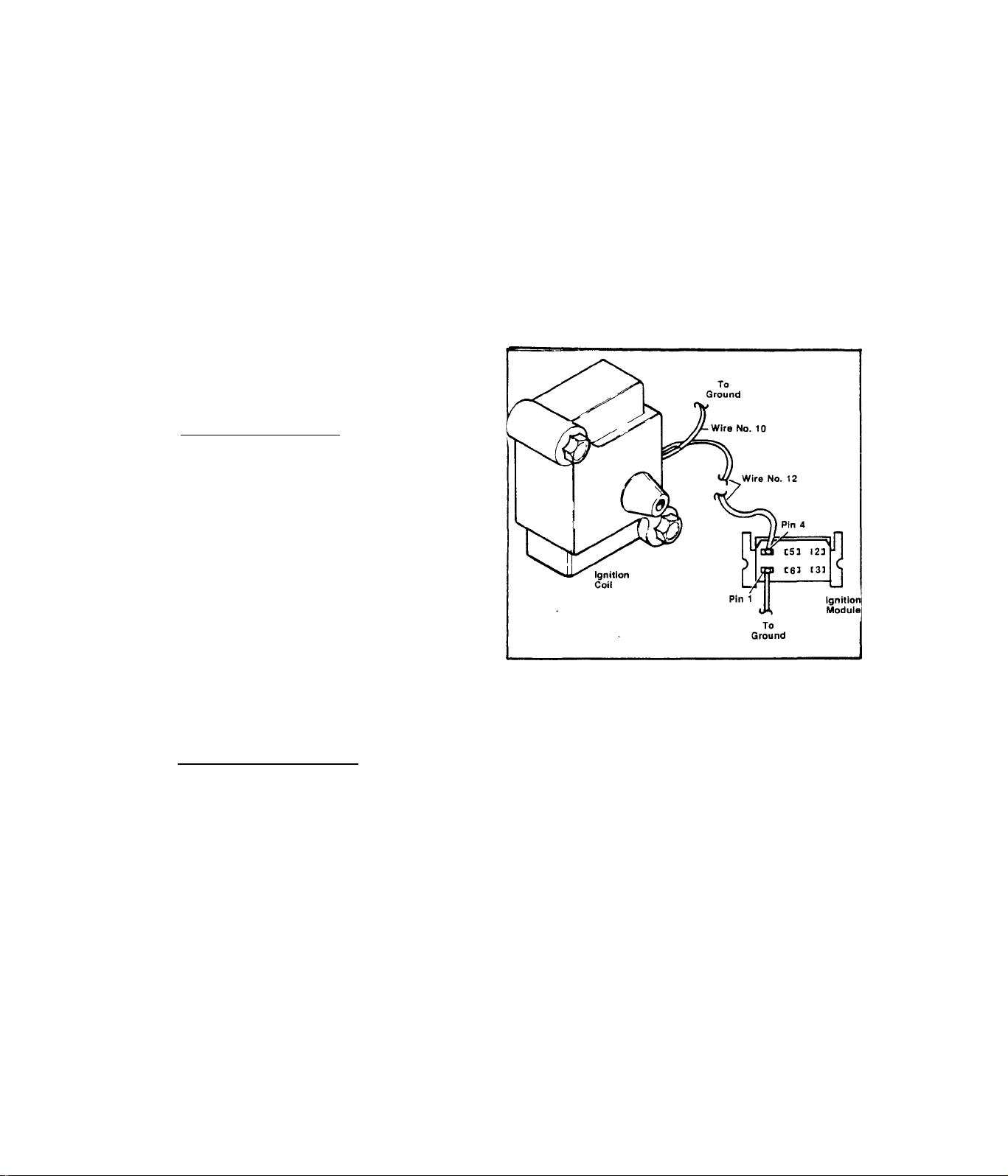
TEST 14- IGNITION COIL
A.)- Primary Winding;- Set VOM to
"Rxl” scale and to ''+DC”. Zero the
meter. Connect the positive (+)
test probe into Pin 4 of the Igni
tion Module receptacle. Connect
the negative (common) test probe
to frame ground. Meter needle
should swing upscale to nearly "O",
RESULT;- Meter needle does not move.............Replace Ignition Coil
Meter indicates nearly "O”.....................Continue test
B,)- Secondary winding; - Set VOM to '’RxlK” and to "+DC”. Zero the met
er. Install spark plug lead into Ignition Coil. Connect one meter test
probe to spark plug end of spark plug lead and the remaining probe to
frame ground. Meter needle should swing upscale and indicate approxim
ately 5000 Ohms (+10%).
RESULT;- Meter needle does not move.......Check spark plug lead for
open condition. If lead is
good, replace Ignition Coil
Meter reads approximately.....................Continue test
5000 Ohms
CAUTION
To prevent damage to Ignition Coil, make sure spark plug, lead and
spark plug are installed and grounded to engine before cranking.
2.2-7
Page 30
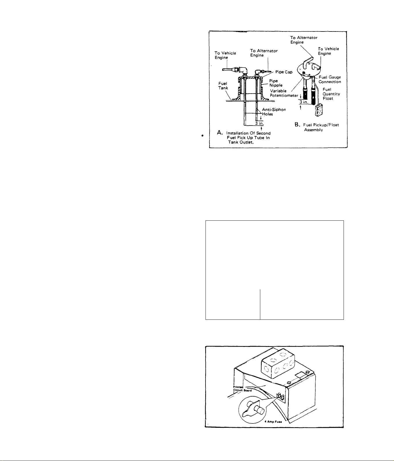
TEST 15:- LOW FUEL
The motor home engine and the alt
ernator engine should "share” the
vehicle fuel tank, through a dual
fuel pickup tube arrangement. See
illustration at right. To prevent
the alternator from depleting the
fuel tank, the alternator fuel
pickup tube is usually several in
ches shorter than the vehicle eng
ine tube. Thus, the alternator may
be "out-of-gas" while the vehicle
engine has a sufficient fuel supply
Make sure the alternator fuel supply line is NOT connected into the ve
hicle engine fuel supply line. If the vehicle engine is running, the
alternator engine may be starved of fuel. When the vehicle engine is
not running, the alternator may drain the vehicle engine fuel line (and
even the vehicle engine carburetor). The latter will result in hard
starting of the vehicle engine.
TEST 16:-NO FUEL FLOW
Disconnect fuel line at Carburetor
inlet fitting. Place open end of
fuel line into a suitable contain
er, then crank engine. Fuel should
pump from open end of fuel line.
If little or no fuel comes from
fuel line, check in-line filter for
clogging. Replace fuel line and fi
lter, if filter is clogged.
RESULTS:- Little or no fuel flow observed
Fuel flow is good
...........................
TEST 17:- 4 AMP FUSE
The 4 Amp Fuse is equipped with a
Fuse Puller Tab for easy removal.
Remove the Fuse from the Printed
Circuit Board and test in same
manner as 15 Amp Fuse (Test 1). If
Fuse is defective, replace.
(NOTE:-Model 6897-4 has no 4 Amp
Fuse. See Section 2.4.)
2.2-8
__
i 1
3>
j "
■j
'I'
>
.............
_
----
CARBURETOR
- IN-LINE FILTER
— FUEL LINE
Continue tests
Go to Test 23
Page 31
TEST 18;- PRINTED CIRCUIT BOARD
A.)- Depress Printed Circuit Board
connector plug locking tangs and
remove connector plug. On the conn
ector plug, locate Pin 4 to which
Wire No. 20 attaches. Set VOM to AC
and to the 2.5 volt scale. Connect
one meter test probe to connector
plug Pin 4, Connect the other test
probe to frame ground. Crank engine.
Meter should indicate a small puls
ing voltage. This is the pulsing
voltage from the Ignition .Stator
trigger coil, which energizes circ
uit board components.
Wir« No. 14
Connection
m
terminal
Strip
, ■ ■■■ ■ ■ —Q— . ■ ■ -1
rs —^ \— ^ -1
__________________________________________
Printed Circuit Board
H
I Module
CD
- EDflO
Ignition
__J— O
1--1 —' jc 0 o'olj
Connector Plug
Receptacle
Connector
Plug (viewed
from Wire end)
NOTE:- For Model 6897-4, refer
to Section 2,4,
RESULTS:- Meter indicates pulsing voltage
.........
.,,Continue tests
No pulsing voltage indicated,..Check Wire No. 20, between
connector plug and terminal
strip, and Wire No. 25 betw
een terminal strip and Igni
tion module for open or shor
ted condition
See illustration above. Locate the Wire No, 14 connection at terminal
strip. Plug the Printed Circuit Board connector plug into its recept
acle. Set VOM to '’+DC” and to "50V” scale. Connect positive ( + ) meter
test probe to terminal strip Wire No. 14 connection. Connect remain
ing test probe to frame ground. Crank the engine. Meter should swing
upscale and indicate 9-12 Volts DC.
RESULTS:- Meter indicated 9-12 Volts
....
Continue tests in Diagnostic
Flow Charts
Meter did NOT read 9-12 Volts..Check Wire No. 14 (between
PCB and terminal strip) for
open or short. If wire is
good, replace Circuit Board
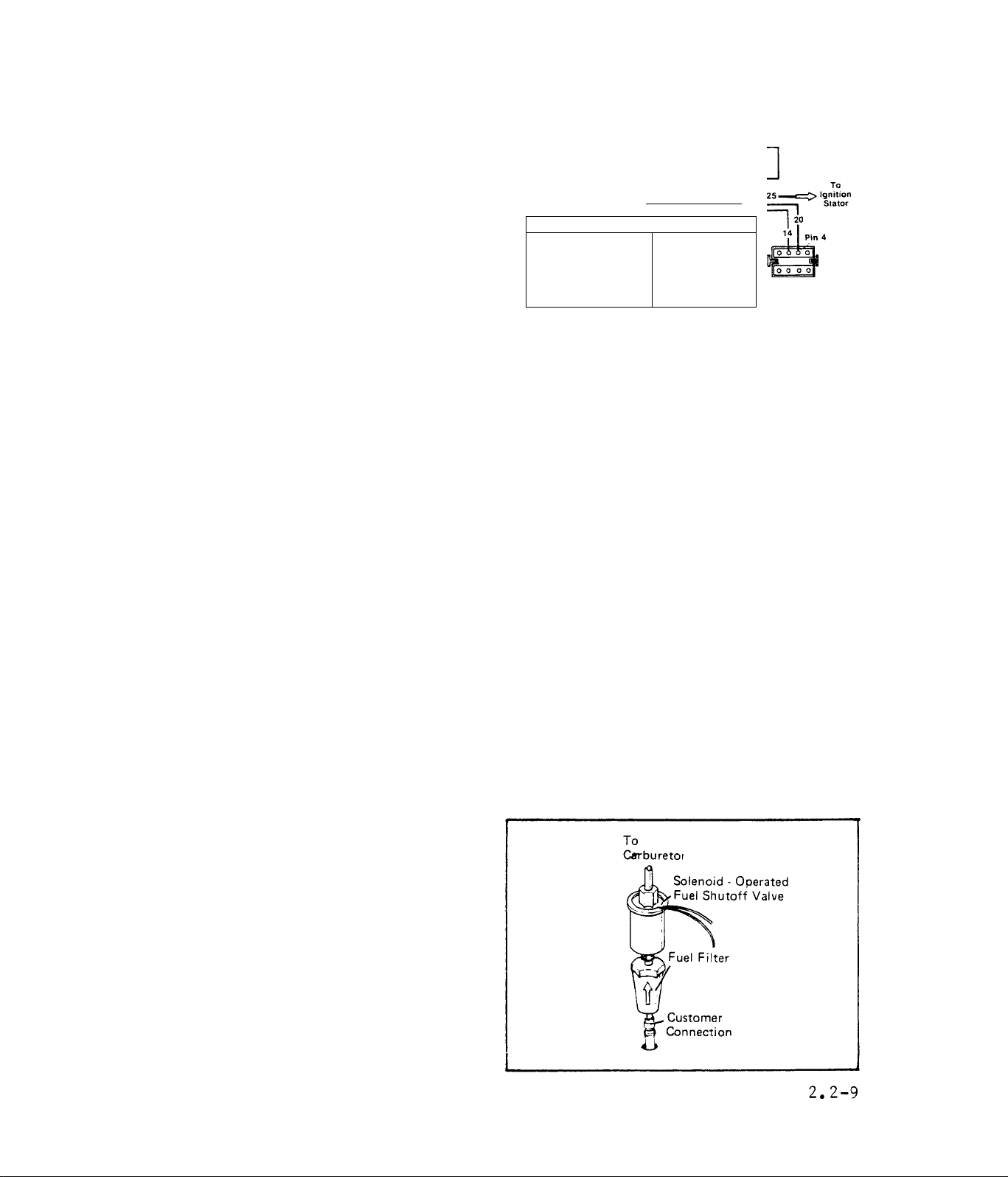
TEST 19:- FUEL FILTER
Remove and replace fuel filter.
Make sure arrow on filter body-
points toward the solenoid oper
ated Fuel Shutoff Valve. Repeat
Test 16 (NO FUEL FLOW).
Page 32

TEST 20;- FUEL LOCK-OFF SOLENOID
A.)- Locate Wire No. 14 between the
Fuel Lock-Off Solenoid and terminal
strip. Disconnect the wire at its
terminal strip connection. Crank en
gine. While cranking, touch Wire No.
14 to its terminal strip connection.
Fuel solenoid should actuate. If the
unit has an electric fuel pump, a
noticeable change in fuel pump sound
will be detected.
RESULT:- Solenoid did not actuate.,.,,
.............
Go to Paragraph B
Solenoid actuates....Continue tests in DIAGNOSTIC FLOW CHARTS
B.)- Disconnect Fuel Lock-Off Solenoid Wire No, 14 at the terminal st
rip, Set VOM to "+DC” and to ”Rxl” scale. Zero the meter. Connect one
meter test probe to the terminal end of Wire No, 14, Connect the rem
aining test probe to frame ground. Meter needle should swing upscale
to indicate resistance of solenoid windings.
RESULT:- Meter did not swing upscale,
.Check Wire No, 14 between sol
enoid and terminal strip for
open condition. Also check the
solenoid ground wire and conn
ection
Meter needle swung upscale,,,
.Replace Fuel Lock-Off Solenoid
and solenoid did not actuate
in Paragraph A
TEST 21:- FUEL PUMP
UNITS WITH ELECTRIC FUEL PUMP
A.)- Disconnect Wire No, 14 at the Fuel Pump, Set VOM to ”+DC' and to
”Rxl” scale. Zero the meter. Connect one meter test probe to the Fuel
Pump Wire No, 14-, Connect the remaining test probe to frame ground.
Meter needle should swing upscale and indicate approximately 50 Ohms',
RESULT:- Pump tests good
Pump test^ bad,
..........................
......
.........................
Go to Paragraph B
Replace pump
C,)- Set VOM to "+DC" and to 50V scale. Disconnect Wire No, 14 at the
Fuel Pump, Connect POSITIVE (+) meter test probe to terminal end of Wire
No. 14, Connect COMMON test probe to frame ground. Crank the engine -
meter needle should deflect upscale and read approximately 12 Volts DC
(battery voltage),
RESULT:- Meter needle daes NOT swing upscale
Meter indicated approximately 12 Volts
2.2-10
.......
.....
Go to Paragraph C
Replace Fuel Pump
Page 33

C.)- Check Wire No. 14, between Fuel Pump and terminal strip, for open
or shorted condition,
RESULT:- Wire No. 14 checks good
Wire No. 14 cheeks bad
............
............
UNITS WITH MECHANICAL FUEL PUMP
Disconnect Piomp Outlet Line at the
carburetor inlet. Connect a press
ure gauge to the line. Disconnect
Pump Inlet Line at the £ue-l lock-
off solenoid and immerse line in
clean gasoline. Crank engine. The
pressure gauge should indicate 1-
3 psi.
RESULT:- Pressure gauge read 1-3 psi
Pressure gauge does -not read 1-3 psi
Repair/replace Wire No. 14
........
Continue Diagnostic tests
Continue Diagnostic Tests
...........
Replace Pump
TEST 22;- CHECK INSTALLATION
Check alternator installation for:-
1. )- Any other filter screens in the fuel supply line from gas tank.
If other filters are found, check for clogging.
2. )- A Shutoff Valve in the fuel supply line. Make sure Shutoff Valve
is OPEN.
3. )- Anything that might restrict cooling air flow, such as air inlet
or exhaust openings too small, clogged air inlet screening, etc.
If cooling air flow is inadequate, interior compartment tempera
tures will be high resulting in possible fuel line vapor lock,
4. )- Alternator fuel pump located too high above fuel supply tank.
Maximum vertical lift for MC units with an electric pump is app
roximately 18 inches, for mechanical fuel pumps approximately 9
inches.
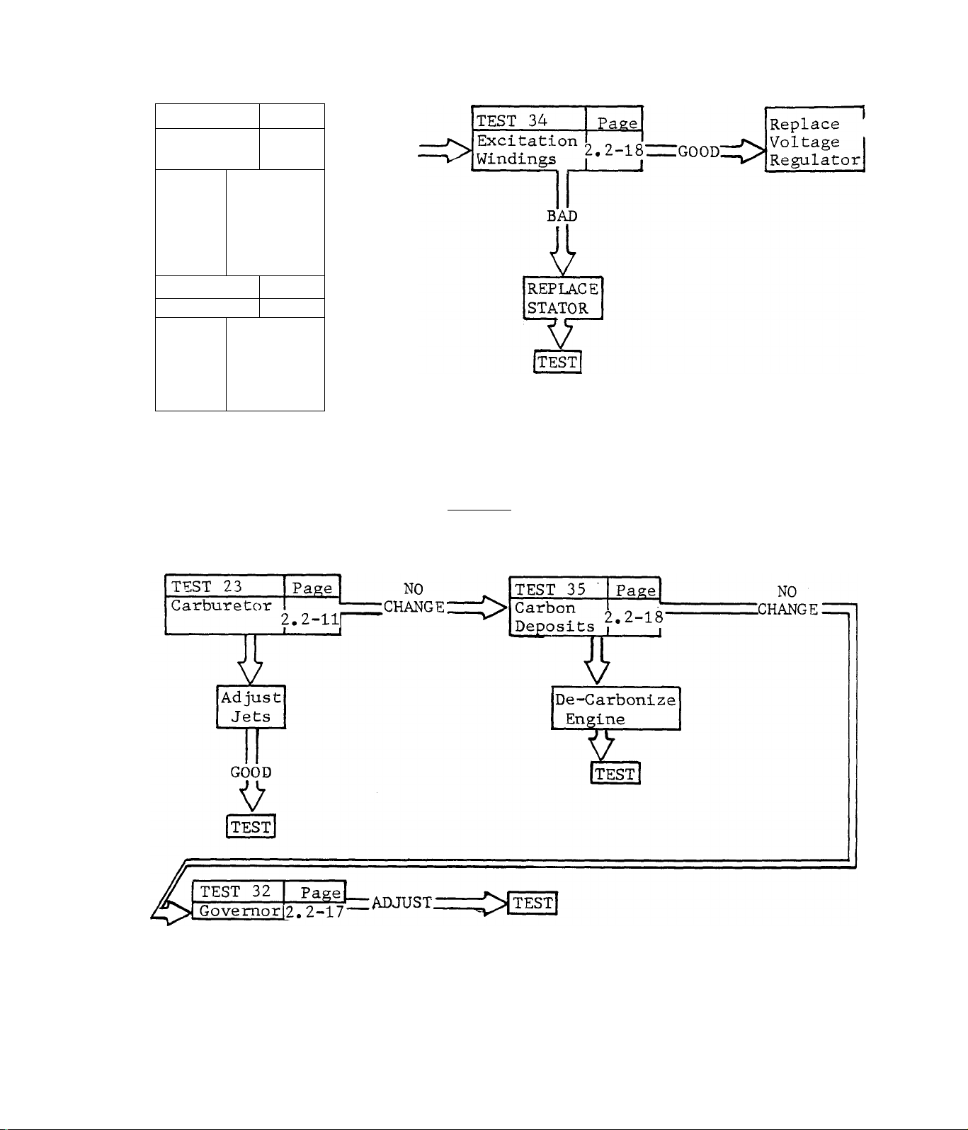
TEST 23- CARBURETOR
This test covers the procedures for adjustment of the carburetor Idle
Speed Stop Screw, Idle Mixture Adjusting Screw, and High Speed Jet Ad
justing Screw. In addition to these adjustments, the float valve and
its seat should be checked, as well as the float level.
2.2-11
Page 34

A.)-Turn High Speed Jet Adjusting
Screw clockwise until it just bot
toms. DO NOT USE EXCESSIVE FORCE.
Then turn High Speed Jet Adjusting
Screw counterclockwise about
turns. Perform the same initial ad
justment on the Idle Mixture Adjust
ment Screw. This initial adjustment
should permit the engine to be star
ted and warmed up.
Automatic Choke
. High Speed Jet
Adjusting Screw
Throttle Lever
Idle Mixture
Adjusting Screw
RESULTS:- Engine starts
Engine will not start
.............................
....................
Go to Paragraph B
Go to Paragraph D
B. )- Set VOM to "250V,” scale and to "AC". Connect the meter test leads
to a convenient AC outlet powered by the alternator. Hold the Carburet
or Throttle Lever against its Idle Speed Stop Screw, Adjust Idle Speed
Stop Screw until meter indicates 60 Volts a-c. When a 60 Volt reading
is obtained, turn Idle Mixture Adjusting Screw until voltage starts to
drop off. Then turn the screw in the opposite direction until voltage
reading again starts to decrease. Finally, reverse direction again and
turn the screw until the highest voltage reading is obtained. Release
Throttle Lever and let engine accelerate and stabilize,
C. )- With engine running at governed speed, apply a normal load to the
alternator. Connect an accurate frequency meter to the unit’s a-c out
put, Turn the High Speed Jet Adjusting' screw slowly clockwise then
counterclockwise until the highest frequency is obtained. When the Jet
is set for the highest possible frequency, turn adjusting screw count
erclockwise 1/8 turn.
RESULTS:- Engine starts and runs normally............Discontinue Tests
Engine will not start or starts and runs
rough
.....................................
Go to Paragraph D
D.)- Remove Fuel Bowl from Carbur
etor Body. Inspect Float Valve,
Seat and Gasket for damage, dirt
or wear. Replace defective compon
ents. Also check for proper Float
setting. Top of Float should be
0.070 - 0.110 inch below Carburet
or Body mounting Flange. See illu
stration at right.
2.2-12
Page 35

RESULT:- Float Valve, Seat, Gasket and
Float level are good
Float Valve, Seat, Gasket or
Float level check bad
TEST 24:- COMPRESSION
A.)-Insert a standard compression
gauge into engine spark plug hole.
Open throttle wide open and crank
engine. Compression should be app
roximately 75-85 psi (cold) or 95105 psi (hot).
.........
........
-...Continue Diagnostic Tests
-Replace or adjust, then test
COMPRESSION
GAUGE
SPARK PLUG
REMOVED
RESULT:- Compression reading good
Compression reading low.......................Continue tests
B,)- Squirt a few drops of clean engine oil into spark plug hole on en
gine cylinder head. Repeat compression test. If compression reading is
higher than was obtained in Paragraph A, ring or cylinder wear is indi
cated, If little or no difference in compression was noted, trouble may
be due to head gasket leakage, worn valves, etc.
RESULT:- Noticeable increase in
compression obtained...............
Little or no increase in compression.
TEST 25:- HEAD GASKET
Crank the engine. A "hissing" sound
at the spark plug indicates the plug
is loose or broken. Likewise, "hiss
ing" at the cylinder head indicates
loose head nuts or a leaking head
gasket. Tighten loose spark plug, re
place broken spark plug using a new
plug gasket. If cylinder head leaks,
check for warped cylinder head and
for a defective head gasket. Refer to
engine section of manual and to TORQ
UE SPECIFICATIONS (SPECIAL).
......................
Go to Test 29
Go to Test 27
Go to Test 25
2.2-13
Page 36

TEST 26:- VALVES
Remove valves. Clean all parts in
non-flammable solvent. Remove all
carbon. Replace damaged or distor
ted valves. If valves are useable,
lap them as outlined in engine se
ction. Check for correct tappet
clearance as outlined in engine
section of manual.
TEST 27:- RINGS
Check for broken or worn rings.
Check ring clearance-in piston
grooves and ring gap. Refer to
engine section of manual.
Valve
Roller Spring Retainer
Valve Spring
Valve Spring Retainer
Tappet
TEST 28:- CYLINDER
Inspect cylinder walls for burning, scoring, or scratching. Check cylin
der inner diameter. Refer to engine section of manual for inspection
requirements.
TEST 29:- TIMING
This Pol« Must Attract Th«
North Soaking Poia Ot A
Magnatic Compass
The ignition magnet is retained to
the fan with a special adhesive
which is cured at 300°F. for 1 hour
(or 265°F. for 1% hours) after ins
tallation. The ring gear is heated
and pressed over the fan and magnet
assembly. The entire assembly is
then balanced as a unit, and finally heated and epoxied into place over
the rotor shaft. Any damage to the
Rotor, Fan, Magnet or Ring Gear is
cause for replacement of the entire
assembly.
2.2-14
Magnai Location astabilshas
Timing At 21* BTDC
Page 37

Timing is established at 21 BTDC by the physical location of the magnet
on the fan. Thus any damage that results in a physical change in the
magnet's location will cause an "out-of-time" condition. Check for a da
maged key or keyway that might have caused slippage of the fan on the
rotor shaft.
TEST 30:- CHOKE
A.)-Crank the engine. The Choke
Solenoid should pulse from Choke
OPEN to Choke CLOSED position at
a rate dependent on ambient tem
perature.
RESULTS:- Choke movement is good
Choke does not move
.............
Go to Test 31, PRE-CHOKE
.......................
Go to Paragraph B
B.)-Check the Choke assembly for
binding or sticking caused by im
proper alignment, dirt, etc. Move
Choke back and forth with fingerthere should be no evidence of
binding or sticking.
RESULTS:- Choke is binding..,
Choke moves freely,
.Adjust or clean choke linkage
............
Go to Paragraph C
C.)- Loosen the two Solenoid Adjusting screws. Adjust axial movement
of solenoid plunger so that, with carburetor choke plate closed, the
choke solenoid plunger is bottomed. Tighten the two adjusting screws
and check again for correct choke action,
RESULTS:- Choke solenoid pulls in normally..............Go to Test 31
Solenoid does not pull in,................Go to Paragraph D
2.2-15
Page 38

D.)-Set VOM to ”+DC'’ and to ”50V.”
scale. Connect the positive (+)
meter test probe to the Wire No. 91
terminal on the choke solenoid and
the remaining test probe to frame
ground. Crank the engine - meter
needle should swing upscale and in
dicate a steady 12 Volts DC.
RESULTS:- Meter does not indicate IZ Volts....Check Wire No. 91 for an
open or shorted condition
Meter indicates 12 Volts DC................Go to Paragraph E
E.)- Set VOM to "+DC” and to ”50V.'' scale. Connect the positive ( + ) me
ter test probe to the Wire No. 90 terminal on the choke solenoid and
the common (-) test probe to frame ground. Crank the engine - meter nee
dle should indicate a pulsing voltage as choke pulses open and closed.
RESULTS:- No meter needle movement
Meter test is good but choke
does not actuate.....................Replace Choke assembly
TEST 31:- PRE-CHOKE
With the choke Bi-Metal at ambient
temperature, the carburetor choke
plate should be approximately 1/8
inch away from its full open posi
tion (toward the closed position).
If necessary, loosen the bi-metal
adjusting screws and move the bi
metal to obtain this setting. This
is the "Pre-Choke" position.
......
Replace Printed Circuit Board
(Model 6897-4:-Replace Choke
Pulse Module [CM]. See Sect-
jL 2 ^ )
2.2-16
Page 39
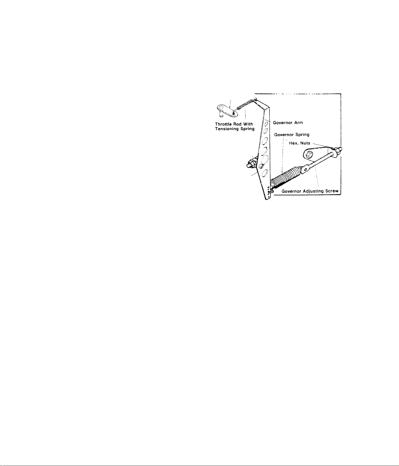
TEST 32;- GOVERNOR
A.)- Adjust Carburetor as outlined in Test 23, The Carburetor must be
adjusted BEFORE attempting to adjust the Governor,
RESULT Problem is corrected...........................Test completed
Engine ’’hunts’’ and/or a-c voltage
or frequency is incorrect.................Go to Paragraph B
_ Carburetor
Throttle Lever
B,)-Make sure Governor Spring is
connected to Governor Arm and to
Governor Adjusting Screw, Loosen
Engine Governor Shaft Clamp Nut
and turn Engine Governor Shaft
counterclockwise as far as it
Engine Governor
Shaft Clamp Bolt,
Nut and Washers
will go. Then tighten Governor
Shaft Clamp Nutand torque to 110
inch-pounds.
Engine Governor
Shaft
RESULT:- Engine runs normal, provides
62 Hertz at no—load..........................Test completed
Engine hunts and/or a-c voltage
or frequency is incorrect
................
Go to Paragraph C
C,)- With engine running, adjust hex nuts at end of Governor Adjust
ing Screw to obtain 62 Hertz at no-load. One hex nut serves as a jam
nut - make sure this nut is tight when 62 Hertz is obtained,
RESULT:- Engine runs normal,,,,.,,"...................Test completed
Engine hunts
...............
Set Carburetor for richer mixture
NOTE
All mechanical governors have a normal offspeed fluctuation,
This is the reaction time of the governor,
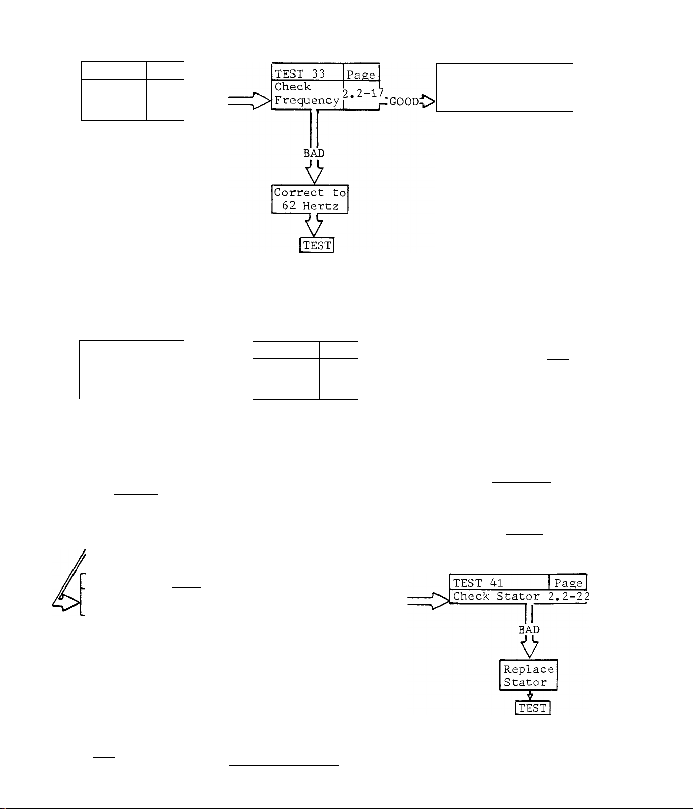
TEST 33;- CHECK FREQUENCY
Use an accurate Frequency Meter to check alternator output frequency.
Frequency should be 62 Hertz at no-load. With a normal electrical load
applied, frequency should be 59-62 Hertz and stable (disregarding the
normal offspeed fluctuation).
2.2-17
Page 40

TEST 34:- EXCITATION WINDINGS
Remove the
assembly.
alternator front panel
Disconnect the white connector plug
from its receptacle on the stator
can. On the receptacle, locate Pin
No. 2 and 6 to which Wires No. 2
and 6 attach. Set VOM to ”+DC’' and
to "Rxl” scale, then zero the meter.
Connect one meter test probe to re
ceptacle Pin No, 2, Connect the re
maining test probe to receptacle Pin
No. 6. Meter needle should swing up
scale and read approximately 1,1
Ohms, This is the resistance of the
excitation winding,
RESULT;- Meter needle does not move
Windings check good
..............
....................
,,,Continue diagnostic tests
Replace stator
TEST 35:- CARBON DEPOSITS
Excessive carbon buildup in the engine combustion section can serious
ly affect engine power. Carbon deposits should be removed every 500
operating hours, whenever the cylinder head is removed, or when prob
lems are encountered. Refer to the engine section of Manual for cylin
der head removal and installation procedures. Cylinder head bolts must
be properly located and properly torqued.
RESULT:- Power output is normal............
Problem is still encountered,
2.2-18
......
........
Discontinue tests
Continue diagnostic tests
Page 41

TEST 36:- CHECK VOLTAGE
Disconnect customer wiring from
Wires No. T1 and T2 in alternator
connection box. Check a-c voltage
output at Wire No. T1 and junction
of Wires T2. Reading should be ap
proximately 125 Volts a-c at no-load
and 115-125 Volts a-c under load.
RESULT:- Vol.tage output bad,,
Voltage checks good.
.Continue diagnostic tests
.....Check customer wiring
NOTE
Alternators are factory connected to provide a 120 Volt a-c output
only. Some units may have been reconnected to supply 120/240 Volts
a-c. See Page 1.2-3.
TEST 37;- SENSING TRANSFORMER
White Connector Plug
A./-Remove 2 wire nuts that connect
wires No. 11 and 22, between Sensing
Transformer and Voltage Regulator.
Disconnect the wires. Set VOM to
”+DC” and to ”Rxl00" scale, then ze
ro the meter. Connect meter test
probes across wires No, 11 and 22
from the Sensing Transformer. Meter
needle should swing upscale and indi
cate secondary winding resistance.
See illustration at right.
Winding Wescoil Coiltran
Primary 785 ohms 969 ohms
Secondary 1886 ohms 1438 ohms
Resistance (± 15%)
RESULT;- Secondary winding resistance checks good
Meter needle does not swing upscale
.......
...
Go to Paragraph В
Replace Transformer
B.)- Unplug the white connector plug from its receptacle on the stator
can. Set VOM to ”-t-DC” and to ”RxlO, 000" scale. Zero the meter. Connect
one meter test probe to white connector plug Pin No. 3. Connect the re
maining probe to white connector plug Pin No. 5, Meter needle should
swing upscale and indicate PRIMARY winding resistance. See illustration
above right.
2.2-19
Page 42
RESULT:- Primary windiag rasistance. checks good..Check customer wiring
Primary winding resistance is bad,.......Replace Transformer
NOTE
The Sensing Transformer secondary windings MUST connect to the
Voltage Regulator, The primary windings..must connect to the
white connector plug. In most cases, primary and secondary wi
ndings will be identified when replacing a Transformer. If the
windings are not identified, check winding resistance. The
winding having the HIGHEST resistance is the SECONDARY winding.
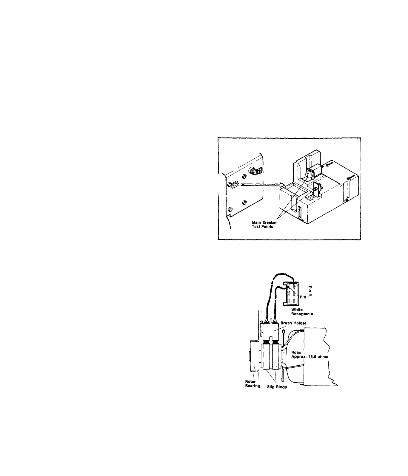
TEST 38:- MAIN CIRCUIT BREAKER
Set VOM to ”+DC" and to "Rxl" scale.
Zero the meter. See illustration at
right. Connect VOM test probes acr
oss the Main Rreaker teat points.
Meter needle should swing upscale to
zero with Main Breaker ON, When the
Breaker is set .to OFF, needle should
drop all the way downscale (infinity),
RESULT:- Main Breaker cheeks good.
Main Breaker feeafes bad.
TEST 39:- CHECK ROTOR
A.)-Disconnect the white connect
or plug from its receptacle on the
stator can. Set VOM to "+DC” and
to "Rxl” scale, then zero the met
er. Connect the positive (+) meter
test probe to white receptacle Pin
4, Connect the common (-) probe to
receptacle Pin 1, Meter needle
should swing upscale and indicate
rotor winding resistance (approxi
mately 15,6 Ohms),
RESULT:- Rotor checks good
Rotor checks bad..
.Continue diagnostic tests
..........Replace Breaker
....
Go to Test 40
,Go to Paragraph B
2.2-20
Page 43
rotor checks bad in Paragraph A, check Wires No. 1 and 4 for an
open or shorted condition. Inspect brushes - replace if cracked, chipp
ed or less than 5/16 inch long. Inspect slip rings and clean with fine
sandpaper, if necessary. Make sure brushes are making good contact with
slip rings. Finally, recheck rotor winding resistance at Pins 1 and 4
of white receptacle as outlined in Paragraph A.
RESULT:- Wires, slip rings and brushes
check good but rotor still
checks bad......................................Replace rotor
Wires, slip rings or brushes
check bad............................Repair, clean or replace
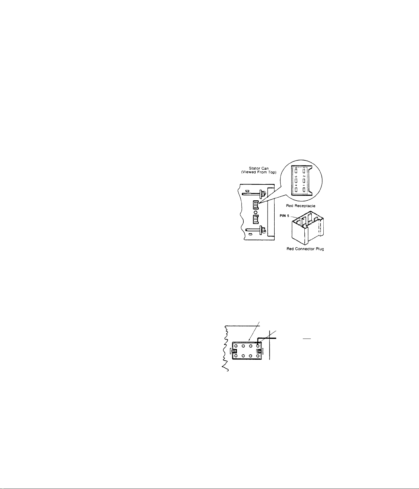
TEST 40:-CHECK FIELD BOOST refe?^to^Section^rr)^°'^'^^^ 6897-4
Unplug the Ignition Module to pre
vent the engine from starting. Al
so unplug the red connector plug
from its receptacle on the stator
can. Set VOM to ”+DC" and to any
scale that will permit 12 Volts to
be read. Connect the positive (+)
meter test probe to red connector
plug Pin 5, Connect the negative
(-) test probe to frame ground.
Crank the engine - meter needle
should swing upscale and indicate
approximately 9-12 Volts d-c,
RESULT:- No field boost valtage indicated
Field boost voltage checks good
B,)-Unplug connector plugs from
the Printed Circuit Board and from
the red receptacle on stator can.
Set VOM to "+DC” and to "Rxl” sca
le, then zero the meter. Connect
one meter test probe to Pin No, 2
of the printed circuit board conn
ector plug. Connect second test
probe to Pin No, 5 of the red con
BOTH CONNECTOR PLUGS VIEWED FROM WIRE END
nector plug. Meter needle should
swing all the way upscale to zero.
RESULT:- Meter indicated, zero,
...
.
Meter did not swing upscale,
..........
....
Continue diagnostic tests
Printed Circuit Board
Connector Plug
Go to Paragraph B
Pin No.2
Red Connector Plug
(On Stator Can)
Wire No.4
k -■ Pin No. 5
.Replace printed circuit board
.Repair/replace Wire No, 4 or
defective connector plug
2.2-21
Page 44

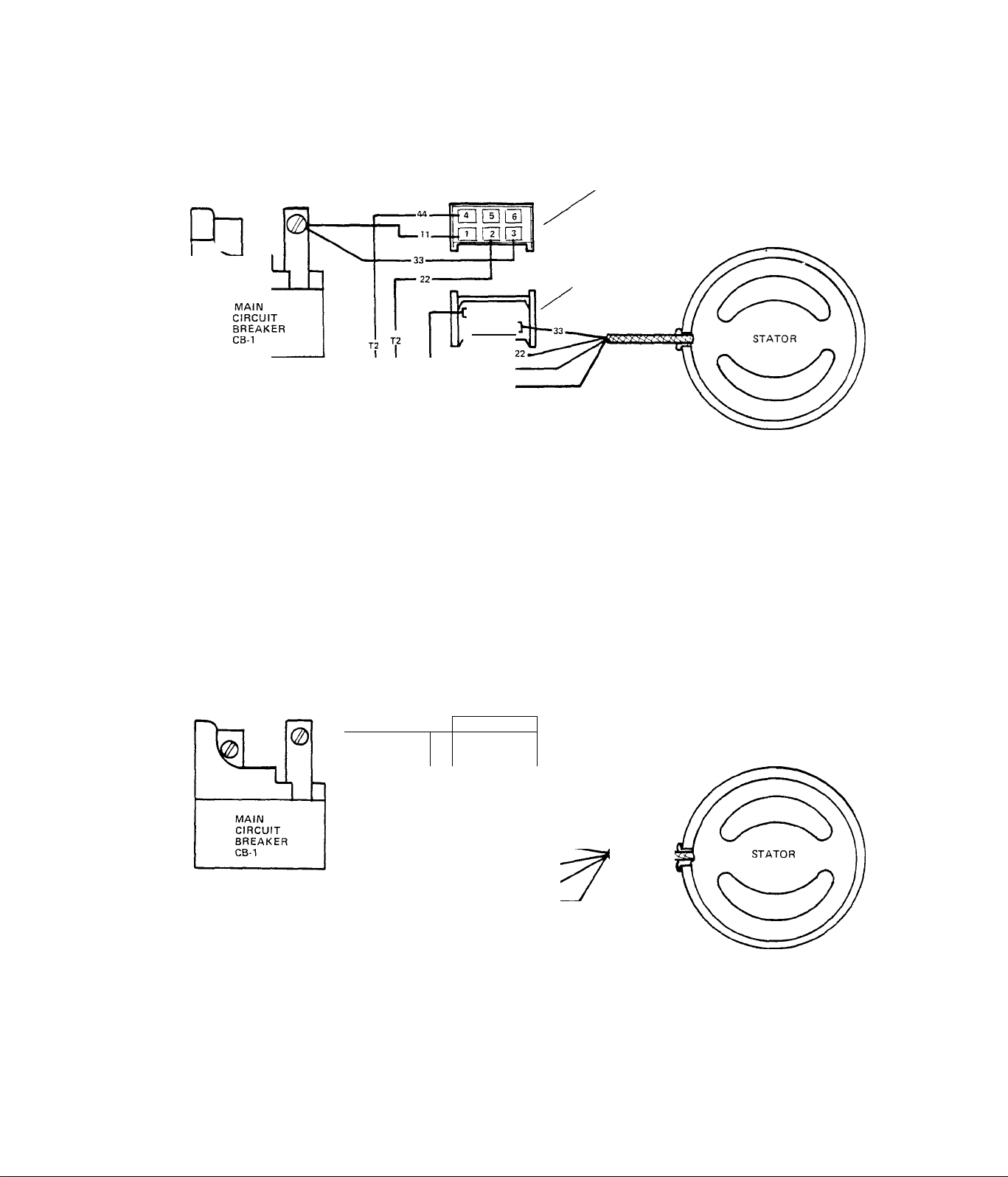
TEST 41:-CHECK STATOR
A.)- Set VOM to ”+DC" and to ”Rxl”
scale, then zero the meter. Connect
meter test probes to Pins 1 and 2
of red receptacle on stator can. Me
ter needle should swing upscale and
indicate approximately 0,42 Ohms.
RESULT, - Meter needle did not move
...................
Replace stator
Checks good................................Go to Paragraph B
B, )- With VOM still set to ”-l-DC” and to ”Rxl” scale, connect meter test
probes to red receptacle Pins 3 and 4, Meter needle should swing up
scale and indicate approximately 0.42 Ohms.
RESULT:- Meter needle did not move
Checks good..-. ....
............ .Go to Paragraph C
....................
Replace stator
C. )- Set VOM to ”+DC” and to ”Rxl0,000” scale, then zero the meter.
Connect one meter test probe to red receptacle Pin 1 and the second test
probe to frame ground. Meter needle should not move. Repeat test with
one test probe connected to red receptacle Pin 3 and the second probe
to frame ground. Meter needle should not move,
RESULT:- Meter needle moved upscale
.................
..Replace stator
Checks good........................Continue diagnostic tests
2.2-22
Page 45
SECTION 2.3
BATTERY CHARGE CIRCUIT
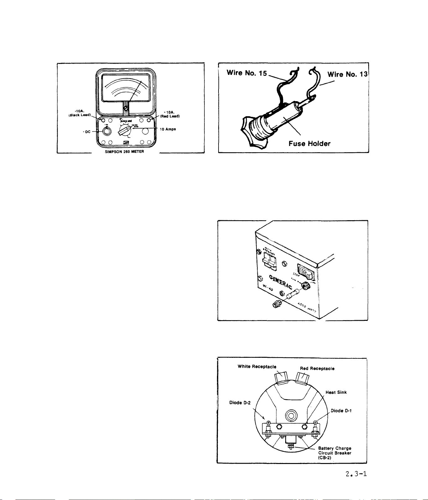
CHARRING CURRENT
1,)- Plug the black (-) test lead
into the "-10A" jack on the VOM.
Plug the red (+) test lead into
the "+10A" jack on the meter. Set
the meter range switch to ”10 Amps”
(dual position with 10 MA).
2.)-Locate the 15 Amp Fuse inside
the alternator control panel. Co
nnect the red meter test probe to
the Wire 15 terminal on the Fuse
Holder, Connect the black test
probe to the Wire 13 terminal on
the Fuse Holder.
TESTS
3.)-Start the alternator. With
the engine running, remove the 15
Amp Fuse from its holder. With
the Fuse removed, the alternator
should indicate a current output
dependent on battery condition.
RESULT:- Ammeter indicates a current output..........Discontinue tests
No current output indicated.,.,
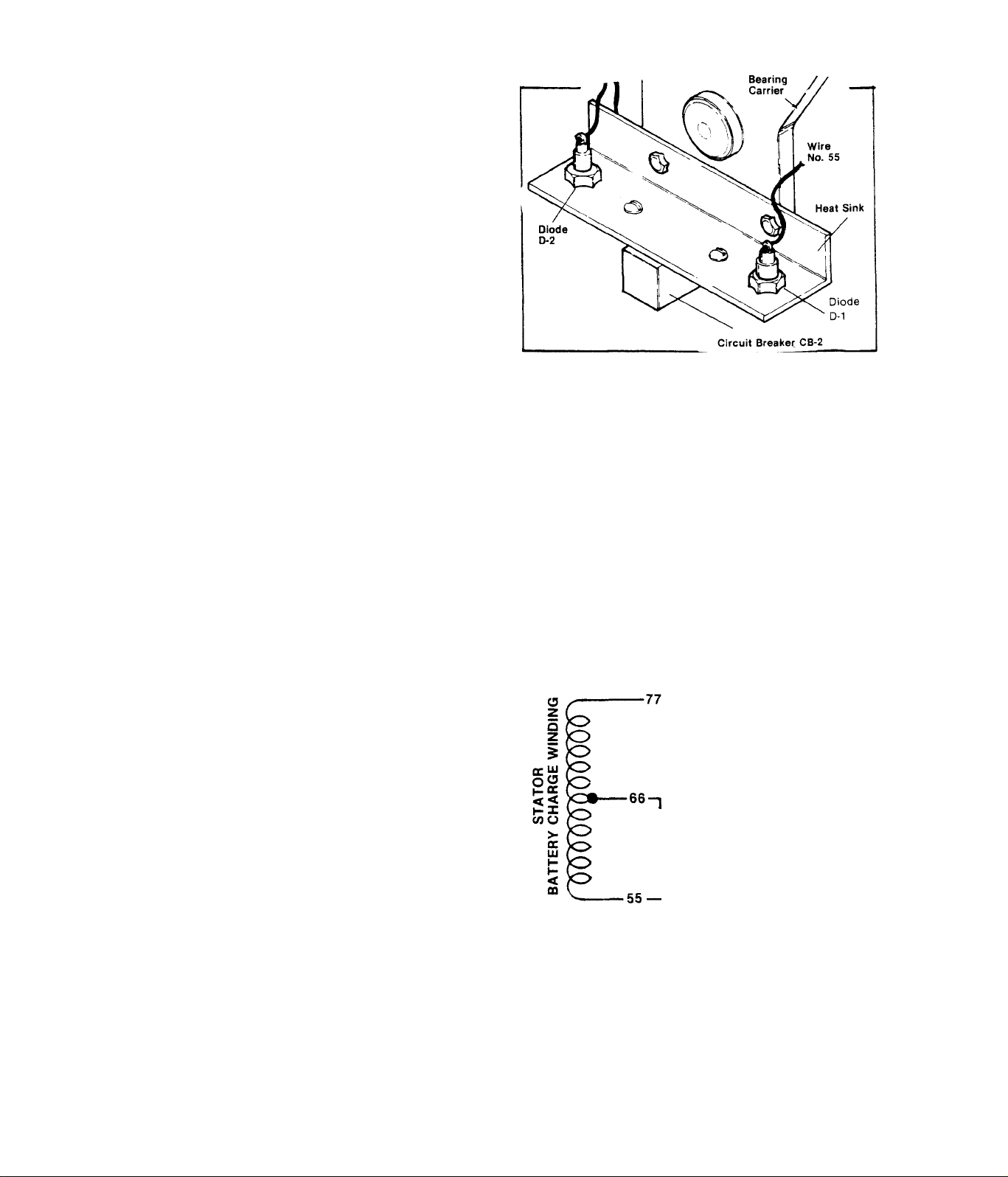
CIRCUIT BREAKER CB-2
Disconnect Wires No, 77 and 78 from
the battery charge circuit breaker
(CB-2). Set VOM to ”+DC” and to ”Rxl”
scale, then zero the meter. Connect
the meter test probes to the circuit
breaker terminal studs. Meter needle
should swing upscale to zero. If it
does not swing upscale, replace the
circuit breaker.
...............
Continue tests
Page 46
DIODES D1 ANDD2
A.)- Disconnect Wire No. 78 at the
circuit breaker CB-2, Set the VOM
to '*+DC” and to ’’Rxl” scale. Zero
the meter. Connect the positive (+)
test probe to Wire No. 78 from the
Diode D-2. Connect the common (-)
test probe to frame ground. Meter
needle should not move. Set meter
to ”-DC", or reverse the meter test
probes. Meter needle should swing
upscale to some mid-scale reading
(approximately 7-12 Ohms).
RESULT:- Diode D-2 tests good...... Reconnect Wire 78,
Diode D-2 tests bad
.....
....
............
go to Paragraph B
.Replace Diode D-2
B.)- Set VOM to ”+DC” and to ”Rxl” scale, then zero the meter. Connect
the positive (+) test probe to the Diode D-1 terminal end. Connect the
common (-) test probe to frame ground. Meter needle should not move.
Set meter to ”-DC” or reverse the test probes. Meter needle should move
upscale.
RESULT:- Diode D-1 tests good.....
Diode D-1 tests bad.............
.....................
...........
...Replace Diode D-1
Continue tests
STATOR BATTERY CHARGE WINDINGS
Disconnect Wire 77 from Circuit Break
er CB-2, Unplug the red connector plug
from its receptacle on the stator can.
To
CB-2
Set VOM to "+DC” and to ”Rxl" scale,
then zero the meter. Connect one meter
test probe to Wire 55 at the Diode D-1
.08 ohm.
Pin 6
terminal. Connect second test probe to
Pin 6 of the red receptacle. Meter
needle should swing upscale (approxim
ately ,08 Ohm). Repeat test with meter
.08 ohm.
€ 0
0 0
RECEPTACLE
00
RED
test probe connected to red receptacle
Pin 6 and Wire 77 - meter should indi
cate approximately .08 Ohm,
To
•DIODE D-1
RESULT; Both meter readings were approximately
.08 Ohm
............................................
Meter needle did not indicate .08 Ohm
2.3-2
..........
Test good
Replace stator
Page 47
SECTION 2.4
MODEL 6897-4
2.4.1-GENERAL
2.4.1.1-INTRODUCTION
The Model 6897-4 (MC-40) alternator incorporates several new components
in its DC control system. The new components replace the printed circu
it board used on earlier models. They will improve starting and simpli
fy component testing, removal and replacement. New components are:-
1. )- Choke Pulse Module (CM)
2. )- Control Relay (CR)
3. )- Field Boost Module (FB)
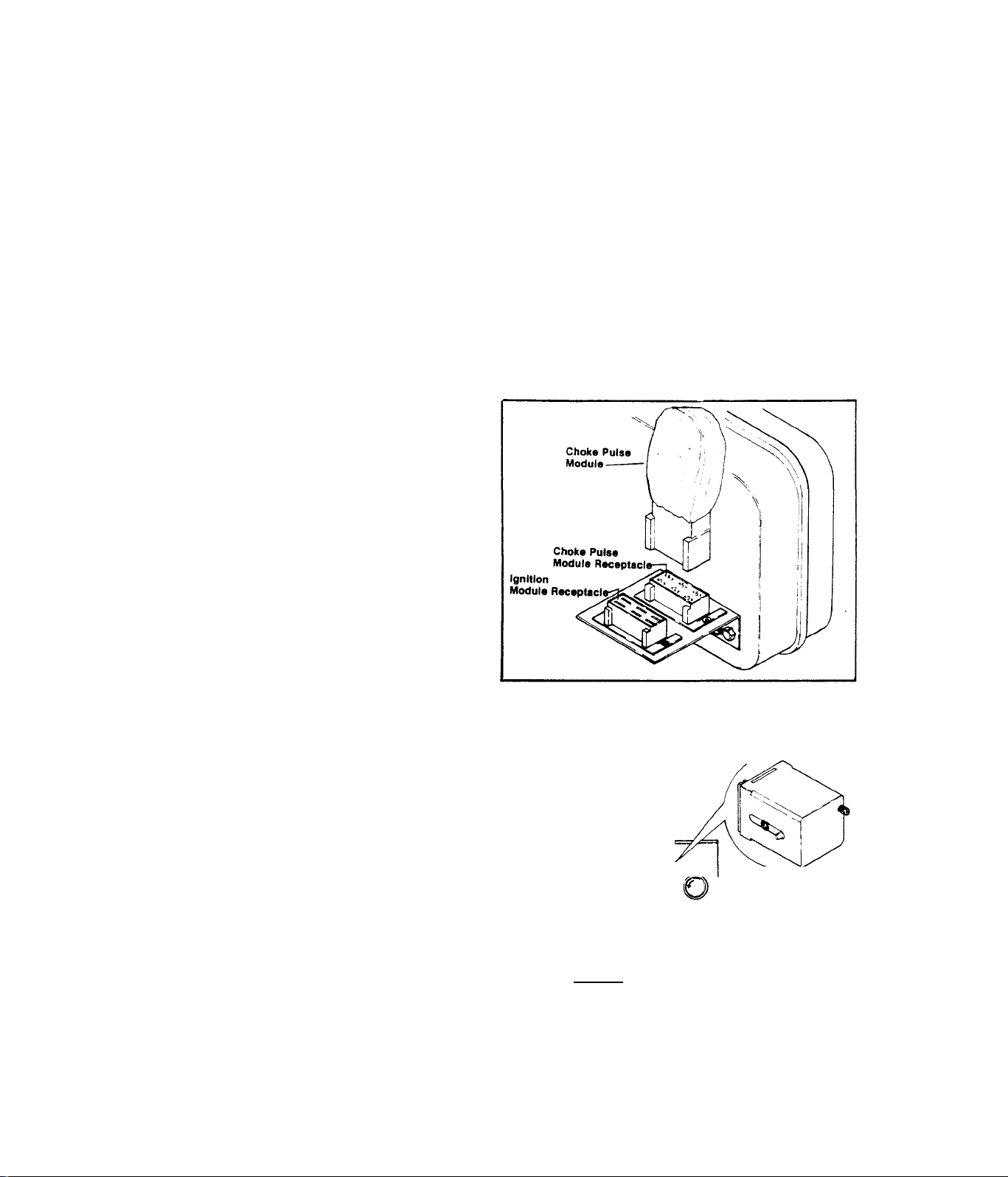
2.4.1.2-CHOKE PULSE MODULE
The Choke Pulse Module performs
several important functions, rel
ated to engine starting. These
functions are:-
1. )-Provides the necessary compo
nents for delivery of a pulsing
voltage to the automatic choke
solenoid during cranking.
2. )-Provides the required circui
try for energizing the fuel lockoff solenoid and (electric) fuel
pump during cranking, before the
control relay (CR) is energized.
2.4.1.3-CONTROL RELAY (CR)
The Control Relay (CR) is equipped
with a pushbutton for manually cl
osing the CR contact. The pushbut
ton can be identified by the words
FUEL PUMP on the unit control pan
el. To prime the carburetor prior
to cranking the engine, depress
the pushbutton. This action will
energize the Fuel Lockoff Solenoid
open and operate the (electric)
Fuel Pump. After a start, the CR
remains energized to hold the Fuel
Lockoff Solenoid open and operate
the Fuel Pump. (While cranking,
part of the Choke Pulse Module cir
cuit performs the latter function.)
MAIN
BREAKER
O
® -©
Q 4000 O I MC-40
WATT "
O
STOP STAUT
------------
Control Relay (CR)
'
2.4-1
Page 48

2.4.1.4-FIELD BOOST MODULE (FB)
Many alternators rely on residual
or ’’stored" magnetic energy to
provide the initial magnetic field
around the rotor windings. Residu
al magnetism can be lost due to
shock or physical damage.
The MC alternator is equipped with
a Field Boost Module (FB) which
supplies battery current to the
rotor windings during each start.
2.4.2- CIRCUIT OPERATION
Battery power is available through Wire No. 13, the 15 Amp Fuse, and
Wire No. 15 to the Control Relay (CR) contacts. When the push button
(FUEL PUMP) is depressed, the CR contacts close. This completes the
12 Volt DC circuit through Wire No. 14, the Fuel Lockoff Solenoid (FS),
Fuel Pump (FP), and the Choke Heater to frame ground. The Fuel Lockoff
Solenoid is energized open and the Fuel Pump operates.
2.4-2
Page 49

2.4.2.2-CRANKING
the 15 Amp Fuse, Wire No. 15, the Starter Contactor (SC), and Wire
No. 17. When the Stop/Stairt Sx<rLtch is set to START position,, the cir
cuit is completed through Wire No. 10 to frame ground. The Starter
Contactor (sc) energizes and its contacts close. With the SC contacts
closed, several events occur as follows
1, )- Battery power is supplied through Wire No. 91 to the Starter Mo
tor and to frame ground. The engine cranks,
2, )- Battery power is supplied through Wire No. 91, through the Choke
Solenoid (CS), Wire No. 90, and to Pin No. 1 of the Choke Pulse
Module (cm). Solid state components within the CM open and close
this circuit through CM Pin No. 2 and Wire No. 10 to ground, at
a rate dependent upon ambient temperature. The Choke Solenoid
(CS) is thus pulsed and the automatic choke operates at a rate
dependent on ambient temperature,
3, )- Battery power is supplied across the closed SC contacts, through
Wire No. 91, to Pin No, 5 of the Choke Pulse Module (CM), The
circuit is completed within the CM, through Pin No. 3, through
Wire No. 14, the Fuel Lockoff Solenoid (FS), the Fuel Pump (FP),
Choke Heater and through Wire No, 10 to frame ground. The Choke
Heater energizes, the Fuel Lockoff Solenoid (FS) opens, and the
Fuel Pump (FP) operates,
4, )- As the engine cranks, the Ignition Stator (IS) supplies a volt
age pulse to the Ignition Module (IM). The Ignition Module in
turn supplies a timed voltage pulse to the Ignition Coil primary
winding. The buildup and collapse of this voltage pulse induces
a voltage into the Ignition Coil secondary winding to fire the
spark plug.
5, )- Battery power is supplied through Wire No, 14 to the Field Boost
(FB) module. A 15 Ohm, 10 Watt resistor reduces this voltage and
a Diode (D3) ensures correct polarity. The reduced voltage is
delivered to the rotor windings via Wire No. 4, 243
Page 50

2.4.2.3- RUNNING
Releasing the Stop/Start Switch to NEUTRAL opens the DC circuit from
the battery. Wire No. 13, 15 Amp Fuse, Wire No. 15, Starter Contactor
(sc), and Wire No. 17. The SC de-energizes and its contacts open to
terminate cranking and choke operation. The Control Relay (CR) is held
energized by AC output from the Battery Charge Windings, and the CR
contacts close. Battery power is delivered through the closed CR cont
acts to the Fuel Pump (FP), Fuel Lockoff Solenoid (FS), and Choke Heat
er to maintain engine operation. The Ignition System continues to func
tion and Field Boost current is still available.
2.4.2.4-SHUTDOWN
2.4-4
Page 51

When the Stop/Start Switch is set to STOP, Ignition Stator (IS) output
from Wire No. 25, Ignition Module (IM) Pin No. 3, Wire No. 25 to the
Terminal Block and Wire No. 20 is delivered to frame ground. Ignition
terminates and the engine shuts down. The Control Relay de-energizes
and its contacts open to close the Fuel Lockoff Solenoid (FS) and ter
minate Fuel Pump (FP) operation,
2.4.3- DIAGNOSTIC TESTS
2.4.3.1- CHOKE PULSE MODULE
METHOD 1:- Install a known good Choke Pulse Module, Crank engine,
RESULT:- Choke operates normally...........Replace Choke Pulse Module
Engine starts.
Choke does not function and/or
....
Continue Diagnostic Tests,
no start Section 2,1
METHOD 2:- A.)-
Unplug Choke Pulse Module, Set VOM
to "+DC” and to ”50V." scale.
Connect positive (+) meter test
probe to Module receptacle Pin No,
1, common (-) test probe to frame
Choke Pulse
Module
ground. Crank engine. Meter should
indicate 9-12 Volts DC. This is
the input voltage to the Choke Pu
lse Module,
Choke Pulse
B, )-Plug Choke Pulse Module into
its receptacle. Set VOM to ”+DC"
Module Receptacle-
Ignition
Module ReceptacI
and to "50V,” scale. From bottom
of receptacle, connect positive (+)
meter test probe into receptacle
Pin No. 1 and common (-) test probe
to frame ground. Crank engine. The
meter should indicate a pulsing
voltage and choke solenoid should
pulse.
C. )-Plug Choke Pulse Module into its receptacle. Set VOM to "+DC" and
to '’50V,” scale. From bottom of Module receptacle, connect positive
meter test probe to receptacle Pin No. 3, Connect common (-) test pr
obe to frame ground. Crank engine. Meter should indicate approximate
ly 12 Volts DC.
RESULTS:-All tests were good..,.Continue diagnostic tests. Section 2.1
Test A checked bad
....
Check Wire No. 90 between receptacle
and Choke Solenoid, Choke Solenoid,
Wire No, 91 between Choke Solenoid and
Starter Solenoid (SC), Starter Solenoid
(SC)
Test B checked bad
....
Replace Choke Pulse Module (CM)
Test C checked bad,,,,.Replace Choke Pulse Module (CM)
2.4-5
Page 52

2.4.3.2- CONTROL RELAY (CR)
Refer to 2.4.1,3 and 2,4.2, this Section, If engine starts and then
shuts down, the problem may be caused by the Control Relay (CR). Pro
ceed as follows to check the Control Relay
A. )-With unit battery properly connected, depress Fuel Pump button.
The Fuel Lockoff Solenoid should open and Fuel Pump should operate.
RESULT :-Checks good,...........................
Checks bad
.........
Check 15 Amp Fuse and priming circuit -
Go to Paragraph B
See 2.4.2.1, PRIMING
B. )-Crank engine while holding Fuel Pump button depressed. Continue
to hold button in after engine starts, then release.
RESULT:-Engine starts and runs normally,
shuts down after button is rel-
.........
Go to Paragraph C
eased
No change - engine starts then,..Continue Diagnostic Tests,
shuts down as before
C. )-Set VOM to "AC", Connect one me
ter test probe to Pin No. 7 of the
Section 2,1
CONTROL RELAY RECEPTACLE
VIEWED FROM WIRE END
CR receptacle. Connect remaining
test probe to receptacle Pin B, then
crank engine. Meter should indicate
approximately 10-12 Volts AC,
RESULT:- Checks good
Checks bad
....
Check wires 15 and 77-
.....
Replace CR
If wires check good,
replace stator assembly
2.4.3.3- FIELD BOOST MODULE
A.)-Unplug red receptacle from its
receptacle on stator can. Set VOM
to "-HDC" and to any scale that
will permit 12 Volts to be read.
Connect the positive (+) meter test
probe to red connector plug Pin No,
5, Connect the common (-) probe to
frame ground. Depress the Fuel Pump
button - meter should indicate app
roximately 9-12 Volts DC.
RESULT:-Checks bad,.....Go to Para
graph B
Checks good
....
Continue
tests. Section
2.1
2.4-6
Page 53

B,)-Set VOM to ”+DC” and to any
scale that will permit 12 Volts
to be read. Connect the positi
ve meter test probe to the Wire
No. 4 connection at Field Boost
Module, Connect the common (-)
test probe to frame ground. De
press the Fuel Pump button- the
meter should indicate 9-12 Volts
DC.
RESULT;-No voltage indicated........................Go to Paragraph C
Voltage is indicated, but none
....
.Repair/replace Wire No. 4
in Paragraph A between red receptacle and Field
Boost Module
C,)-Set VOM to ”+DC” and to any scale that will permit 12 Volts DC to
be read. Connect the positive (+) meter test probe to the Wire No. 14
connection at Field Boost Module, Connect the common (-) test probe
to frame ground. Depress the Fuel Pump button. Meter needle should iftdicate 9-12 Volts DC.
RESULT:-Normal DC voltage indicated
but not in Paragraph B
No voltage indicated
..........Check Wire No. 14 between
.......
Replace Field Boost Module
the Field Boost Module and the
Control Relay (CR)
2.4-7
Page 54

PART III
DISASSEMBLY &
Section 3.1
3.1.1
3.1.2
3.1.3
Section 3.2
3.2.1
3.2.2
3.2.3
Section 3.3
3.3.1
'3.3.2
3.3.3
BLOWER SHROUD SECTION
Disassembly
Inspection and Repair
Reassembly
ALTERNATOR SECTION
Disassembly
Inspection and Repair
Reassembly
ENGINE SECTION
Disassembly
Inspection and Repair
Reassembly
REPAIR
Page 55

3.1.1-D1SASSEM<^LY
SECTION 3.1
BLOWER SHROUD SECTION
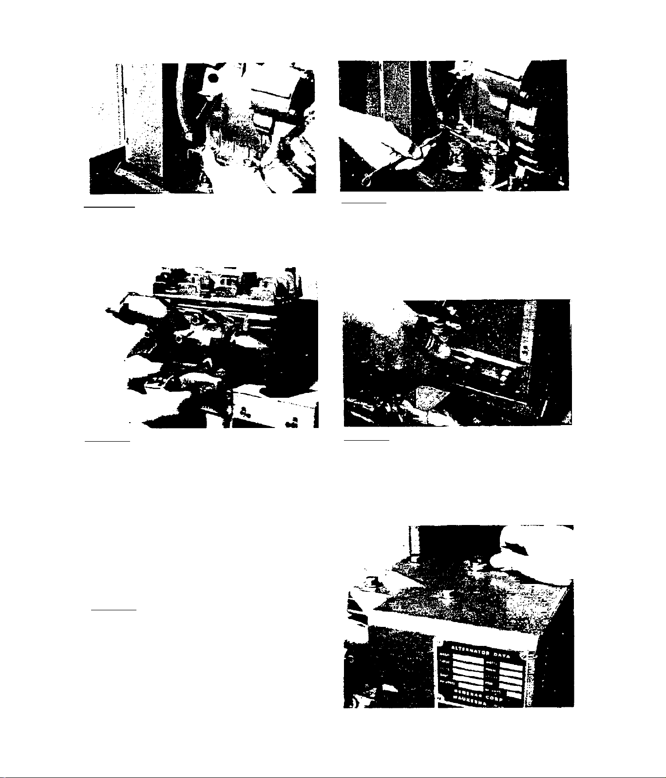
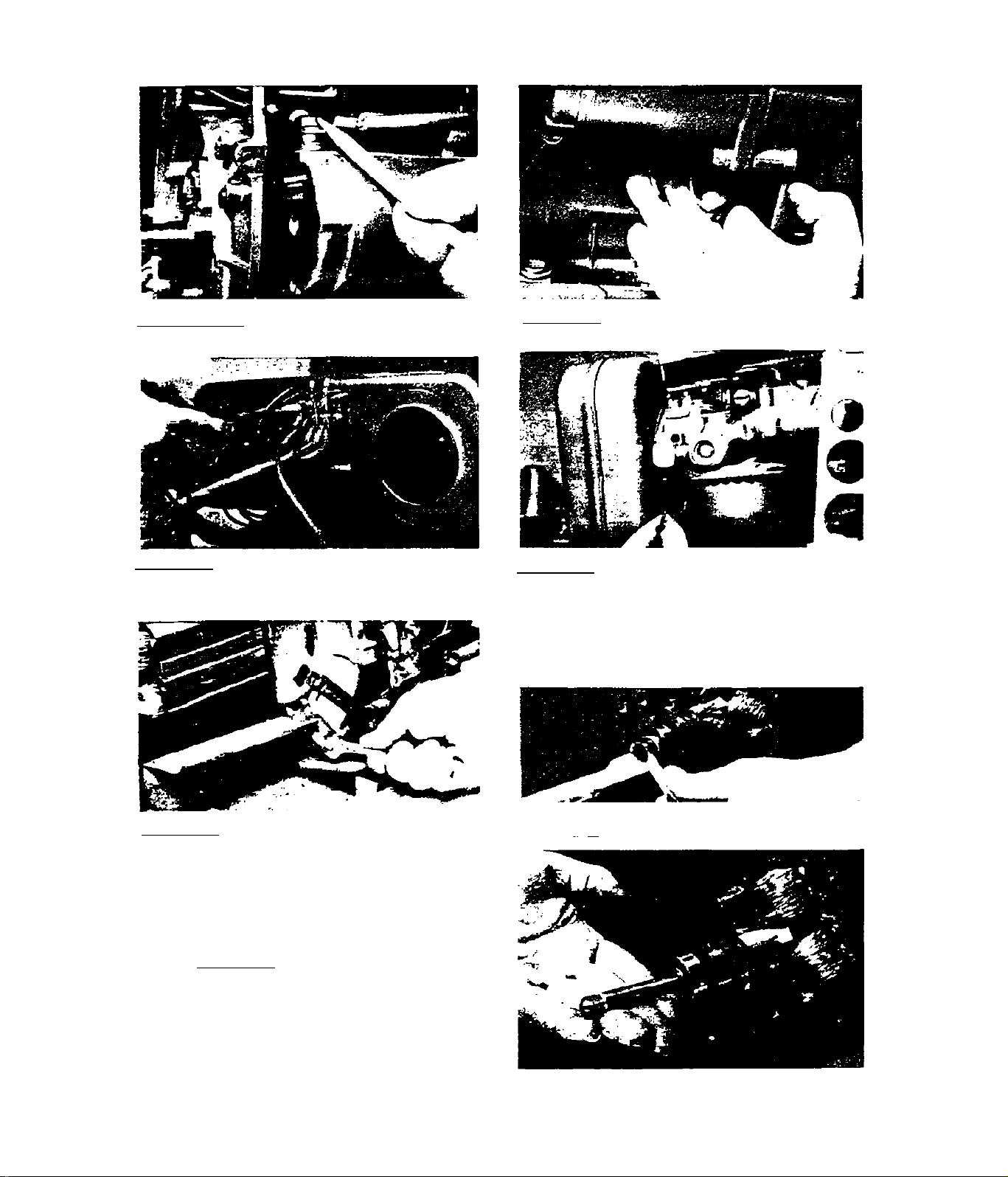
3.1 .1 .1 -IT.sp R 5/16 Inch nut driver
to remove screws and flat washers
Chat retain blower shroud end pan
el. Remove end panel.
3.1.1.3-Insert a screwdriver into a
cooling air slot of engine adapter
housing to prevent ring gear from
Cuming.
3.1.1.2-Reiiiuve philllps head screws
that retain blower inlet ring. Rem
ove blower inlet ring.
3.1.1.4-While preventing ring gear
from turning, remove the special M-
14 hex nut that retains the blower
fan hub to engine Caper shaft.
3.1.1.5-Tnstall three 5/16-24 bolts
into threaded holes of blower fan
huh. Install a puller as shoi^n at
right and pull blower fan and blow
er fan hub free of engine taper
shaft.
3.1-1
Page 56

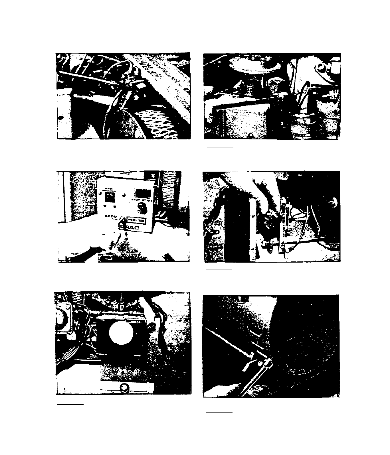
2#_l_Ll2_6-Use a lO nim \^пгRт^ch to rem
ove blower, scroll bolts nearest the
pngine taper shaft. The bolt at low
er right comer of blower scroll ex
tends through the shrouding and is
retained by a lock washer, flatwasher and hex nut on shroud exterior.
Use a 7/16 inch wrench to remove the
bolt and nut.
3.1.1,7-RemoVP four MlO bolts and
four lockwashers that retain Che cy
linder head cover. Remove cylinder
head cover.
Wmm
3.1.1.8-Remove two M8 socket head 3.1.1.9-Remove bolt and washer Chat
capscrews that retain the exhaust
pipe to engine.
retains housing and exhaust pipe
support to vibration dampener.
il
3.1,1,lU-Use a nut driver to remove
screws that retain blower housing
upper ends to engine. Remove blower
housing.
3.1-2
Page 57

3.1.2-INSPECTION AND REPAIR
Clean and degrease all components, including sheet metal* Inspect all
parts as follows
1*)- Carefully check all sheet metal for cracks or other damage. Repair
or replace damaged sheet metal*
2. )- Inspect all weld nuts.
3. )- Check foam rubber gaskets on blower shroud sheet metal* Replace
all damaged strips.
4. )- Inspect blower fan for cracks or other damage. Replace, if damaged.
5. )- Inspect blower fan hub. Replace, if cracked or damaged or if key
way is worn* Also check key and key^^ay on engine taper shaft*
3.1.3-REASSEMBLY
3.1.3.1-Retain blower shroud and 3.1.3.2-Retain blower shroud at
blower scroll to cylinder block
with two M5 X 10 mm capscrews and
Inckwashers. Tighten capscrews to
90-110 inch-pounds.
3.1.3.3-With exhaust pipe u-bolt
and housing and exhaust pipe sup
port loosely retained by 2 hex
nuts, lockwashers and flatwashers,
retain housing and exhaust pip«
support to engine base and vibrat
ion damper.
both sides of cylinder block
with M6 X 15 mm long capscrews,
Inckwashers and flatwashers.
3.1-3
Page 58
3.1» 3,4-Loosoly retain blower hou
sing support to opposite vibration
damper with capscrew, lockwasher
and flatwasher.
3,1,3,^"Retain blower housing and
scroll to blower housing support
(installed in previous step) ^^th
b-20 X ^ inch long bolt and flaLwasher and a hex nut, flatwasher
and lockwasher. Tighten the hex
nut. Finally, tighten all bolts that
thread into the vlhratlon dampers.
3,1,3,6-Slide exhaust pipe down
through blower housing ^nd through
exhaust pipe u-bolt. Install exha
ust flange gasket. Retain exhaust
pipe to exhaust flange with an M8
X 50 ram long and an M8 x 20 mm long
socket head capscrew and lockwash-
prs.
3,1,3,8"Retaln cylinder head cover
with four MlO X 20 mill long bolts
and lockwashers. Tighten bolts to
12 foot-pounds. TnsLall all No. 10-
32 screws that retain head cover to
blower housing.
3,1,3,7"Tightcn exhaust pipe u-bolt
hex niiLs,
3.1-4
Page 59

3^1,3>9-Align keyway in blower fan
hub wlCh drive key on engine shaft.
Install blower fan over engine
shaft. Make sxire drive key and key
way are engaged. Install special M-
14 hex nut and flatwasher. Prevent
crankshaft from turning, then torq
ue hex nut to 50-55 foot-pounds.
3.It 3#11-Install blower shroud end
panel. Retain with No. 10-32 screws
and flatwasherst
3.1.3.lO-jnstall inlet ring as
sho\smi. Retain w1 th No. 6-32 x
3/8 inch long screws and lock-
washers.
3.1-5
Page 60
3.2.1-DISASSEMBLY
SECTION 3.2
ALTERNATOR SECTION
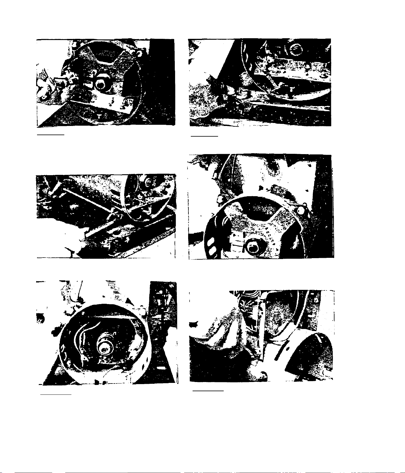
3#2»1«1-At the terminal strip, dis
connect Che Wire No. 20 chat comes
Truiu the low oil level shutdown sw
itch.
3.2.1.3“Remove 4 screws that retain
irront panel. Remove front panel.
3.2.1.2“Loo3en oil line clamp at
oil make-up pump. Slide clamp down
hose, then disconnect hose from
pump fitting.
3,2,1.6-Unplug the red connector
plug from Its stator can recepLacle,
Also remove ground wire, retained
by panel divider screw.
3.2.1.5-Remove screws that retain
rear panel. Remove rear panel.
3.2.1.6-Remove end panel.
3.2-1
Page 61
3.2,1,7~St:raighCpn brush holdei'
locking tangs on bearing carrier,
Kemove brush holder from carrier.
Remove brush leads from brushes
and remove brush holder and brus
hes .
3,2.1,9-Remove two bottom stator 3,2.1,10-Remove 6 screws that ret-
bolts and stator bolt bar.
3,2,1»d-Remove al temator support
to vibration dampener bolts.
aln bearing carrier to stator can,
Remove bearing carrier, using a
puller.
3,2,1.11-Ramove 2 upper stator
bolts and stator holt bar.
3.2-2
3,2.1.12-RGmove panel divider. The
stator can may now be removed as
well.
Page 62
3»2., 1« 13-Remove starter cable at
the starter terminal.
3.2.1.14-Cur Wires No. 8 and 25
that go to the ignition stator.
3.2.1.15-At the terminal strip,
disconnect the wire from the fuel
lockoff solenoid.
3.2.1.l7-Rcmovc bolts, nuts and
washers that retain the adapter
casting. Remove carburetor to
intake manifold nuts, then rem
ove adapter casting.
3.2.1.19-Use rotor removal kit
to remove rotor. (See Section
1.3, SPECIAL TOOLS.) Use the
5/16-24 tap from kit to cut
threads in totor as shown at
right.
3.2.1.16-Remove fuel Line at carb
uretor. Carburetor to intake luaui-
fold iiuLs may also be loosened at
this time. These nuts will be cionipletely rpTTioved prior to removal
of the adapter casting (Step 3.2.
1.17).
3.2.1.18-Remove -rotor bolt.
3.2-3
Page 63
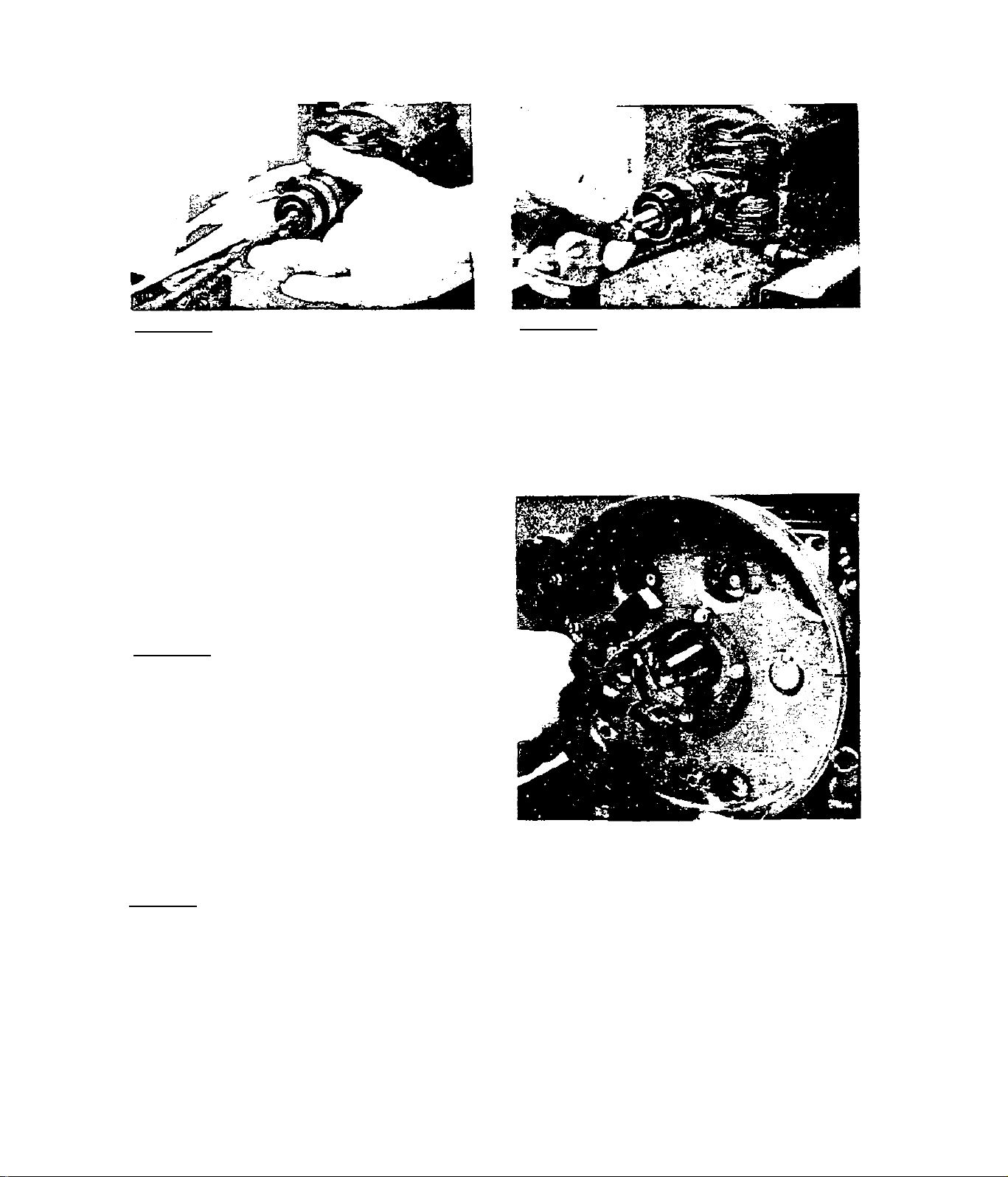
3,2,1,20~SelQcc a stud from the
kit that is long enough so that,
when the stud is threaded into
the engine crankshaft, the slot
ted end of the stud will extend
approximately Inch into the
rotor shaft. Thread the stud in
to the engine crankshaft.
3,2,1,22-Remove the ignition stat
or.
3,2,1,21-Thread the 5/16-24 bolt
(included with rotor removal kit)
into the rotor shaft until It Is
fiinnly seated against the stud.
Tighten the bolt against the stud
and tap the bolt head with a mal
let, Continue tightening and cap
ping until rotor is free. Remove
Che rotor and fan assembly.
3.2.2-INSPECTION AND REPAIR
3,2,2,1- GENERAL
Inspect wiring for pinching, obvious damage, defective insulation.
Clean all parts and Inspect for-obvious damage, cracks, etc. Check
connector plugs and receptacles for damage, pins pushed out of
sockets, etc. Repair or replace damaged, defective parts as requir*
ed.
3.2-4
Page 64

3,2,2,2- BRUSH HOLDER AND BRUSHES
3.2.2.3- BEARING CARRIER
Replace brush holder if cracked or
otherwise damaged. Replace brushes
if cracked, chipped or less than
5/16 inch long.
3.2>2.4- STATOR
Inspect closely for damage. Use an
insulation breakdown tester and test
for breakdown under load. Follow the
tester manufacturer's instmactions
carefully. See 1.1.3, ELECTRICAL
TEST SPECIFICATIONS.
Once removed, the bearing carrier
should not be re-used. Replace the
bearing carrier during reassembly.
3.2.2.5- ROTOR
Inspect closely for damage. Use an
insulation breakdown tester to test
for breakdown under load. Follow the
tester manufacturer's instructions
carefully. See 1.1.3, ELECTRICAL
TEST SPECIFICATIONS.
3.2.3- REASSEMBLY
3,2.3,1-During reassembly, torque fasteners as specified in Section 1.1.4,
TORQUE SPECIFICATIONS (GENERAL) or 1.1.5, TORQUE SPECIFICATIONS (SPECIAL),
as applicable. Do not attempt to re-use worn, defective or damaged parts.
The bearing carrier should not be re-used once it has been removed.
3.2-5
Page 65

3> 2,3« 2"Ignition scacor mouncing
holes are offset to make improper
Installation difficult. Install
the ignition stator and retain
with No. 10-32 X 3/8 inch screws.
3.2.3.3-Isnition stator wires (No.
8 and 25) were cut during disassem
bly. Tf wires are Coo short for pr
oper splicing after unit is assemb
led, additional wiring lengths must
be added at this time. Above, knife
edge connectors were used to add
the additional wire length. Heat
shrink tubing was then installed and
shrunk over the coimecLors. (NOTF:Some later production units may be
equipped with quick disconnects at
these wires for ease of maintenance.)
3.2.3.4-Pull both ignition stator
wires through the hole provided in
Che engine gear cover. Retain \i7ires
flush against gear cover with RTV-
103.
3.2.3« 6-Install rotor. Make sure
key and keyway are engaged. In
stall rotor bolt, lockwasher and
2 flatwashers. Tighten rotor bolt,
making sure rotor pulls in as the
bolt is tightened. When rotor is
tight and will pull in no further,
loosen rotor bolt. Then tighten
bolt Co 15-17 foot-pounds.
3.2-6
3.2.3.5-Inspect Woodruff key and
keyway on engine Caper shaft and
rotor. Replace key if damaged or
worn. Install key into keyway on
engine taper shaft.
Page 66

3¿_2jj_3_2_7-Align adapter casting with
bolt holes in engine gear cover.
Install casting, making sure the
carburetor intake manifold studs
are aligned with carburetor. At
the lower right comer of casting,
retain wi Lh a x 2'^ bolt
\d.th square nut. Also retain with
two 'i/ló-lS X 2^” bolts, lockwashers and hex nuts. Upper left corn
er of casting will be retained by
a 5/16-18 X 4" bolt and hex nut,
which will aslo retain the starter.
3.2.3.8-Iastall a new carburetor
to intake manifold gasket. Retain
carburetor to intake manifold with
two -^-20 NyLok nuts.
3.2.3.9-MechanicaI Fuel Pump Only:
Install fuel pump, inlet filter,
solenoid shutoff valvp, interconn
ecting hoses and clamps. Retain the
fuel pump with two M6 x 18 mm sock
et head capscrews and lockwashers.
Tighten capscrews to 25-30 inch
pounds.
3.2.3.10-The fuel pump to carburet
or fuel line contains a filter
screen. Install clamps over fuel
line. Then connect line to carbur
etor inlet fitting and fuel pump
outlet fitting. Retain line with
clamps.
3.2-7
Page 67

1.2*3, ll-CoiuifeicL Wire No, 14 (the
longest vTire) from the fuel lockoff solenoid Co Lhe termtnal strip.
Refer to appropriate wiring diagram
for wiring connections.
3.2,3.12-wlres No. 8 and 25 from
the ignition stator were cut during
disassembly, (NOTE;-Some later pro
duction units may have a quick dis
connect on these wires.) If wires
were cut, strip wire ends and inst
all a knife edge coiiuecLor.
3.2.3,13-Install heat shrink tubing
over Che connectors on Wires 8 and
25.
3.2-8
3,2.3.14-install starter bolt. The
upper starter holt (5/16-18 x 4")
passes through starter, engine
gear cover and adapter casting. Lower
starter bolt is a 5/16-18 x 1'* socket
head capscrew. Tighten starter bolts,
then torque adapter casting bolts (in
cluding 4 inch long starter bolt) to
120 inch pounds» Finally, install the
starter cable and retain with hex nut
and lockwasher.
3.2.3.15-Careful 1v align stator and
install over rotor.
Page 68

n pane.l dividpr to sta
tor can with two taptite screws. The
ground wire (No. 10) previously dis
connected from Stop/Start switch ter-
minal connects to one of these screws. lower stator bolts are install-
3.Z.ii. 1 / -Install upper stator bolt bar.
Install both upper stator bolts. Only
the two upper stator bolts have a spac
er. Bolts can be tightened later, after
3.2.3.18-Apply a small amount of Loc-
Tite to rotor bearing outer diameter.
Install a new bearing carrier. Retain
3.2.3»19-Install alternator supp
ort onto vibration dampeners. Re
tain with two 3/8-16 X 3/4” bolts
carrier to stator can with four No. 10-and iockwashers. Install the low-
32 X 3/8" Taptite screws. er stator holt bar. Install two
lower stator bolts with lockwashers. Tighten all 4 stator bolts.
Make sure stator can is flush ag
ainst adapter casting, then
tighten all 4 stator bolts to 80100 inch pounds.
3.2-9
Page 69

3.2.3.20-Connecc 2 red wires (No. 3,2.3.21-Sllde brush holder lock-
A) to brush that will he nearest
Che rotor bearing. Retain \^th a
No, 6-32 Sims screw and 2 exter
nal lockwashero. Connect 2 ground
wires (No. 10) to remaining brush
with Sims screw and 2 lockwashers
ing grooves over bearing carrier
locking tangs. Make sure brushes
contact slip rings properly. Bend
bearing carrier locking tangs to
retain brush holder.
3.2.3.22-Retaln brush ground wire
(No. 10) to heat sink with heat
sink retaining screw.
3.2-10
3.2.3.23-Install end panel. Ret
ain to stator can with two No. 10-
32 X 3/R” Taptite screws. (A small
grounding lug is also retained by
one of these screws.)
Page 70

3« 2» 3,24-Install rpar panel with
voltage regulator. Connect read
and white connector plugs into
their receptacles. Install front
panel• Connect ground wire (No.
10) to center terminal of stop/
start switch.
3.2.3,25-lnstall oil make-up tank
with piimp. Connect oil lines to
pump and probe, retain with clamps.
Connect Wire No. 20 from low oil
level shutdown switch to terminal
strip (see appropriate wiring dia
gram) , Connect ground wire from
low oil level shutdown switch and
from fuel lockoff solenoid to the
tapped hole on adapter casting, along with fuel lockoff solenoid clamp
3,2-ll
Page 71

3.3.1- DISASSEMBLY
SECTION 3.3
ENGINE SECTION
3.3.1. l-Dlsconnect. governor spring
from governor adjusting screw. Loo
sen governor arm'clamp bole and re
move governor arm from governor
shaft.
3.3.1.3-Ramovp engine from alterna
tor slide pan.
1 f
3.3.1.2-Remove spark plug.
3.3.1.4-Remove breather assembly.
i i I
3.1.5-Remove intake manifold elbow. 3.1.1_._6-Remove engine cowling.
3.3-1
Page 72

3,3*1« 7-Remove 8 cylinder head uuts.
Remove cylinder head and head gasket:«
3.3.1.8-Intake and exhausC valves
are shown in a sectional view ab
ove. Valve springs are retained
Co valve stems by valve retainers
and a roller pin. Keep valve parts
together as a set. Intake valve is
identified by the letter ”1” on
3,3«l,9~Use valve spring compressor
Co compress valve springs. Then re
move roller pin from valve stem.
Remove compressor, Chen remove valve
springs, spring rpLaine.rs and valves.
3.3.1.11-Remove thrust washer from
end or cam shaft.
3.3-2
3,3.1»10-Drain engine oil. Remove
all bolts chat retain engine bear
ing cover. Rotate crankshaft to
place its keyx^ay at 12:00 position
(top dead center of piston stroke).
Install screws into ignition stator
screw holes. Use these screws and a
puller Co remove bearing cover.
Page 73
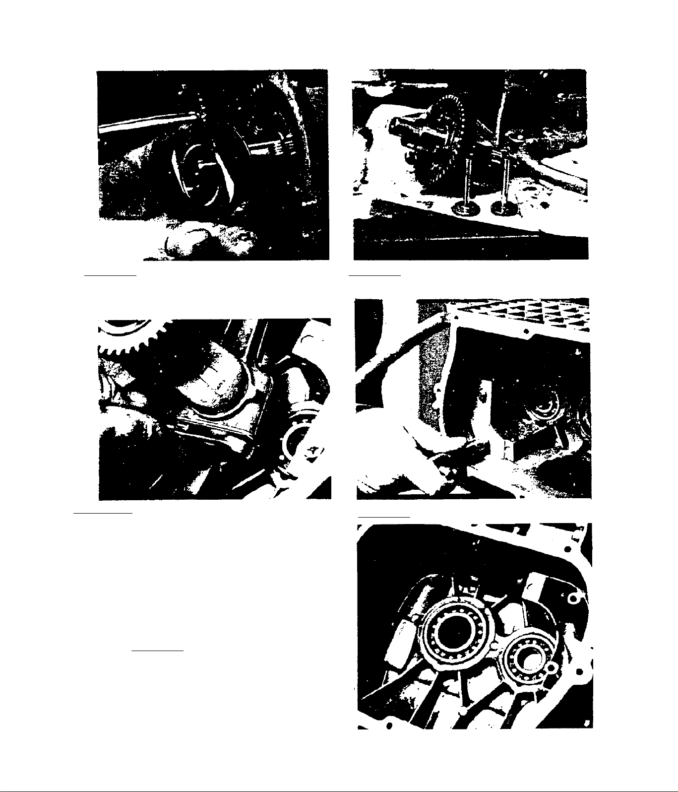
3,3,l.l2-RGmovc governor slider from 3.3.1.13-Remove cam shaft and valve
end of cam shaft. tappets*
3* 3*1*14-Bend lock Cab ends away from
connecting rod bolt heads. Remove the
connecting rod bolts, lock tab, oil
splasher and connecting rod lower half.
Push piston and connecting rod up
through cylinder and remove. Remove
crankshaft.
3.3.1.16-It is not necessary to
remove bearings unless replace-
menc is necessary. Bearings
must be pressed out of cylinder
block.
3.3.1.15-Remove oil stopper,
3.3-3
Page 74
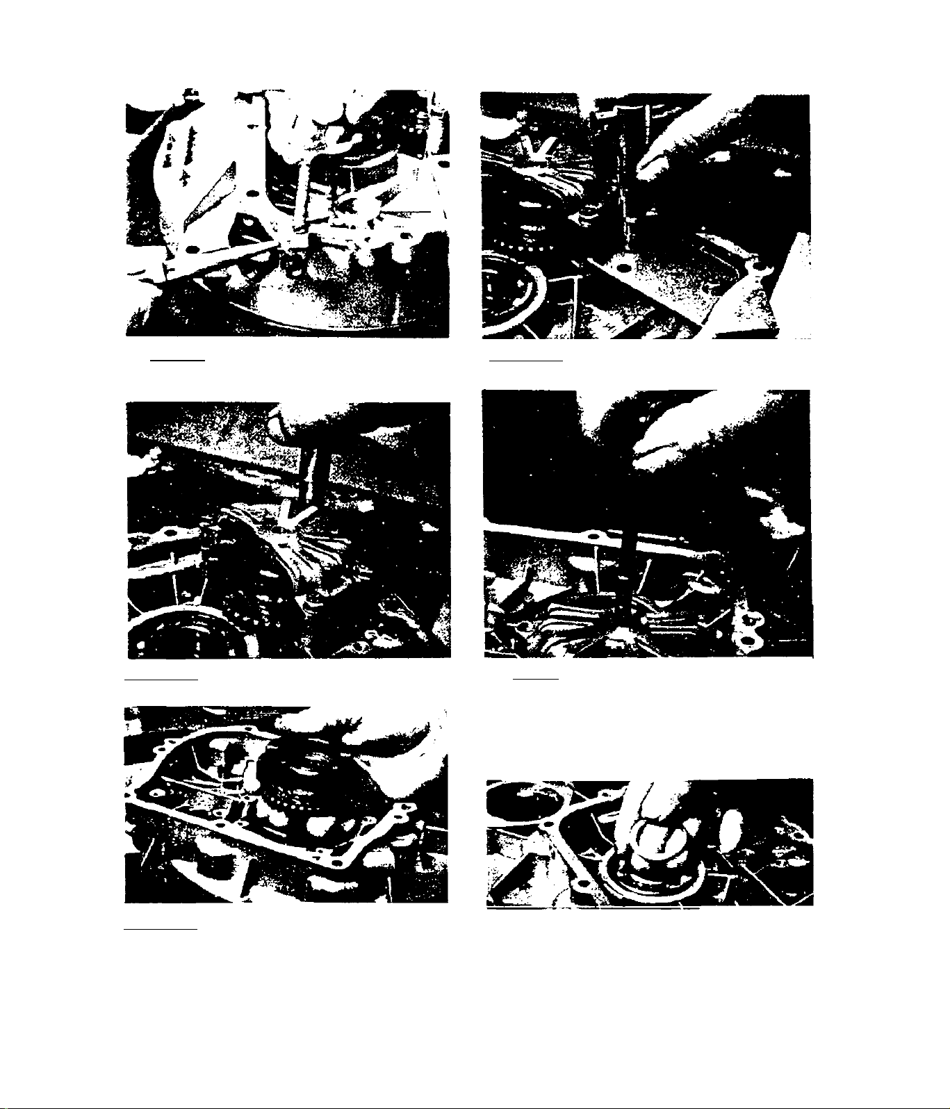
3.3.1.17-Remove governor shafL
retaining clip and governor
shaft.
3.3.1.18-Remove oil stopper from
engine bearing cover.
3.3.1.19-Remove bolts that ret
ain counterbalance cover.
3.3.1.21-Remove counterbalance
assembly.
3.3-A
3.3.1.20-InstaII a bolt into the
threaded hole at top of counter
balance cover. Tighten bolt aga
inst counterbalance shaft until
cover is free of shaft, then i*e-
move cover.
3.3.1.22-$him washers are used at
bearing cover end of crankshaft
to establish crankshaft end play.
Check uumber of shims- during re
assembly, the same number of shims
must he used.
Page 75
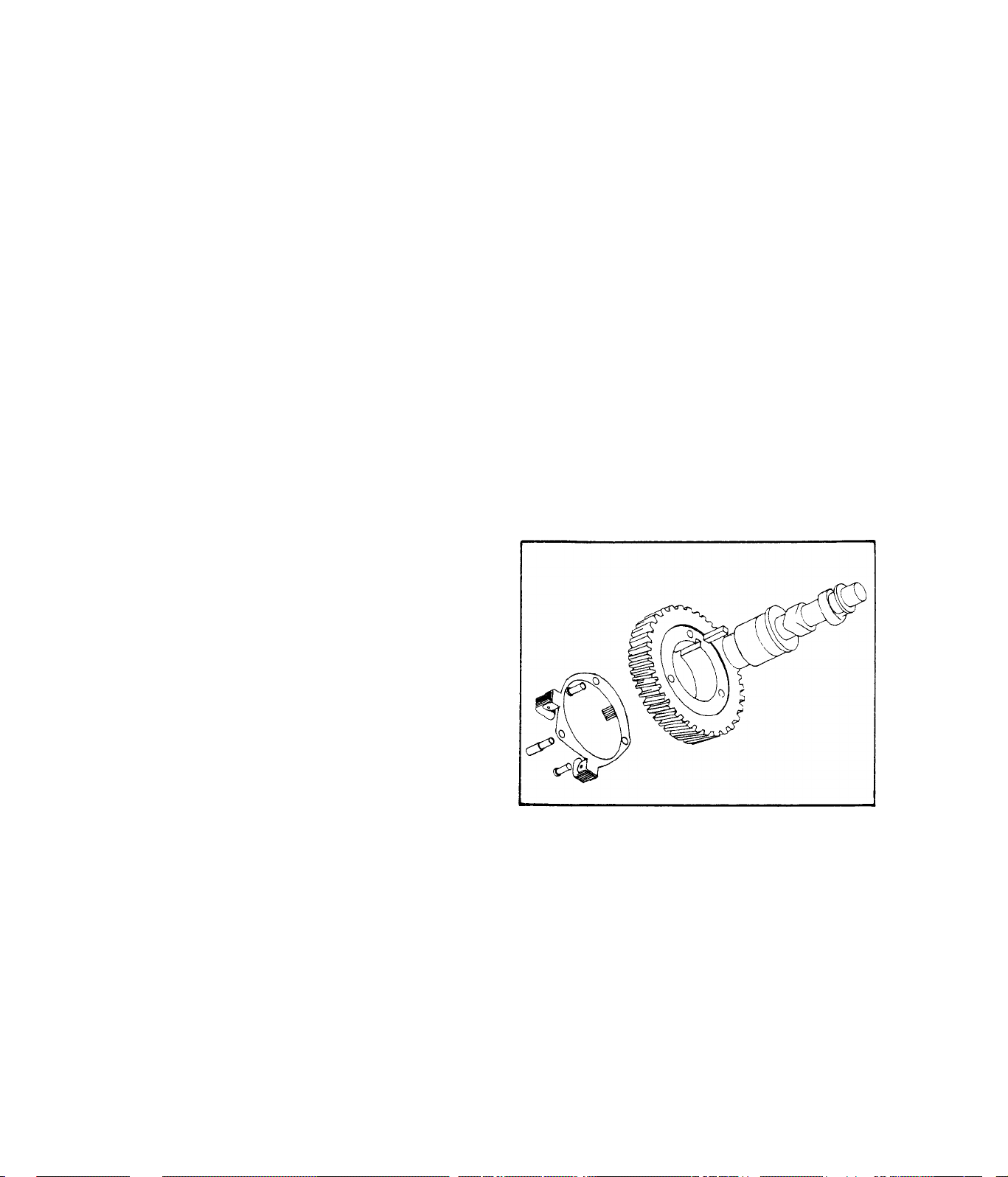
3.3.2- INSPECTION AND REPAIR
3.3.2.1- CYLINDER BLOCK
Replace cylinder block i£:-
a. )-Fins are broken or cracked
b. )-Head mounting surface is warped
c. )-Cylinder inner diameter is greater than 0,5 mm oversize.
If cylinder is to be rebored, first determine whether to bore 0,25 mm
or 0,50 mm oversize. Use any standard commercial hone of a suitable
size. Chuck the hone in a drill press having about a 600 rpm speed.
Use standard boring procedures.
Valve seats require grinding only if pitted or scored. If seats are
not pitted or scored, lapping will provide a satisfactory valve seat.
Valves must be lapped to seats when seats are reground,
3.3.2.2- ENGINE GEAR COVER
Clean and degrease engine gear cover. Replace if cracked, warped, or
damaged,
3.3.2.3- CAMSHAFT
Clean camshaft in non-flammable
solvent and blow dry. Replace a
camshaft that shows signs of
wear or scoring. If a damaged
camshaft gear is replaced, also
replace the mating crankshaft
gear. If keyways are damaged or
worn, replace camshaft. Inspect
keys, replace any that are dam
aged or worn excessively. Repl
ace flyweight or governor shaft
if damaged.
3.3.2.4-CRANK SHAFT
Replace crankshaft if:-
a. )- Damaged threads can’t be dressed
b. )- Bearing surfaces are worn, scratched or damaged
c. )- Flat spots have developed
d. )- Crankshaft is bent - NEVER TRY TO STRAIGHTEN A BENT CRANKSHAFT
e. )- Crankpin is out-of-round more than 0,002 inch
When installing a crankshaft, always lubricate bearing surfaces. If the
camshaft drive gear on crankshaft is replaced, replace the mating cam
shaft gear as well. The crankshaft must be shimmed during assembly to
establish an end play of 0,0039 to 0,0118 inch.
3,3-5
Page 76

measure piston
Piston diameter
3.067”-3.068”
3.3.2.5-PISTON
Clean carbon from piston ring gro
oves, as well as from upper cylinder
bore and head» Check piston dimensi
Check for proper width of compression
and oil ring grooves on piston. See
illustration above.
ons, as shown above. Replacement pi
stons are available in 3 sizes standard, 0,25 mm oversize and 0.50
mm oversize.
3.3.2.6- RINGS
Replace rings in sets. During installation ring gaps must be staggered,
Before installing new rings, deglaze cylinder walls thoroughly with
fine emery cloth and clean thoroughly. Rings are available in standard
size, as well as oversize to match the oversize pistons that are avail
able.
___
_________________________
Check for proper clearance of
compression and oil control rings
in piston grooves. See illustration
at right.
3.3-6
Page 77
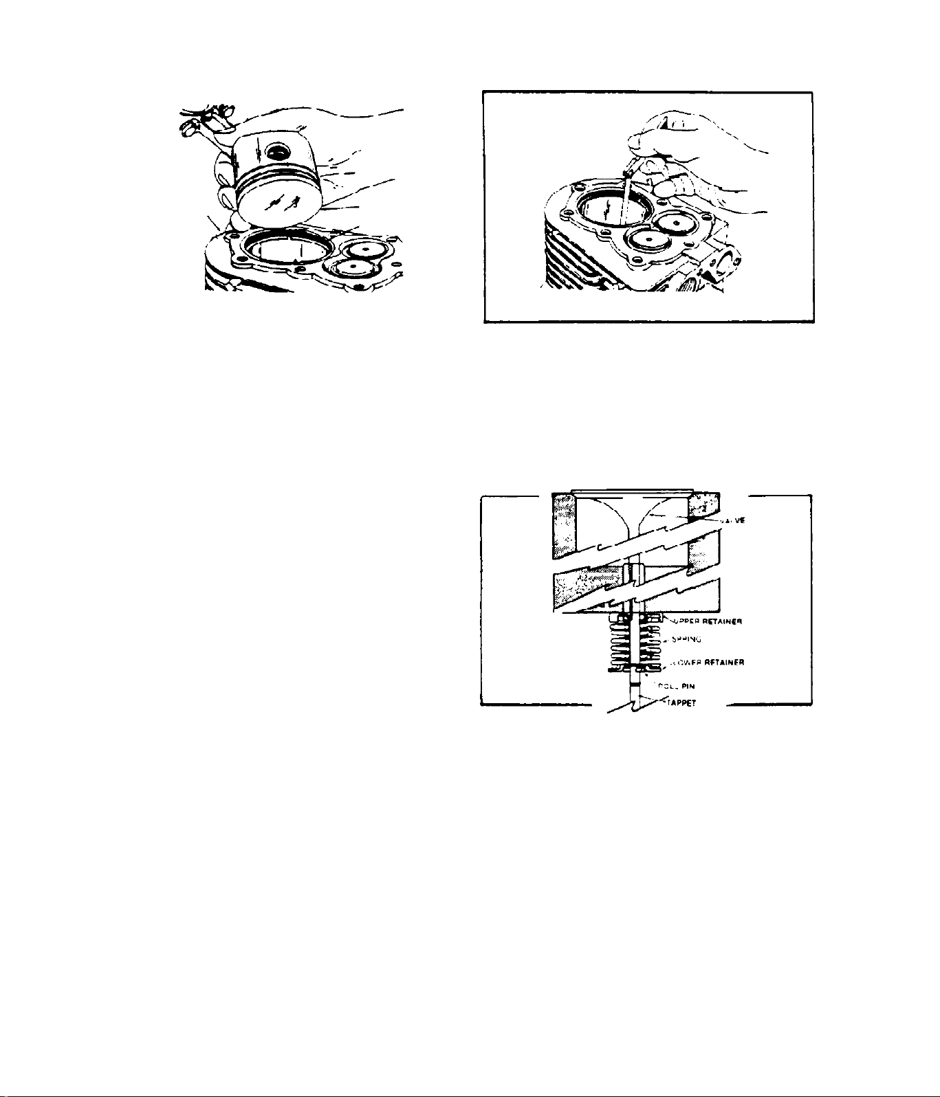
CTLINCW
PISTON
,pi3TON Ring
Check ring gaps on worn rings to
determine if rings should be re
placed. Check gaps on new rings
to determine if cylinder should
be rebored. To check ring gap,
square the ring in the cylinder
bore as shown above.
After squaring the ring in bore,
use feeler gauge to check ring
gap.
3.3.2J-VALVES
Intake.and exhaust valves are NOT
identical - intake valves are id
entified by the letter ”1”, exhaust
valves by an "E**.
Clean valve parts in iion-Clainmahle solvent. Remove carbon from valves.
Replace distorted or damaged valves. If valves are useable, they may
be ground to a 45 degree angle. When new or re-ground valves are to be
installed, lap them to ensue a gas tight fit. Lap valves as follows
1. Coat valve face sparingly with a fine grade of valve grinding comp
ound.
2. Rotate valve on valve seat. Lift valve from seat every 8-10
strokes to keep compound equalized on surface of valve seat.
3. Continue lapping until both the valve and seat has a smooth surf
ace. Clean thoroughly to remove all traces of lapping compound.
Dry thoroughly.
To obtain correct valve tappet clearance, grind ends of valve stems
off squarely. Use a V-block to hold valve stem square to grinding
wheel. After grinding, check for proper clearance as follows
3.3-7
Page 78
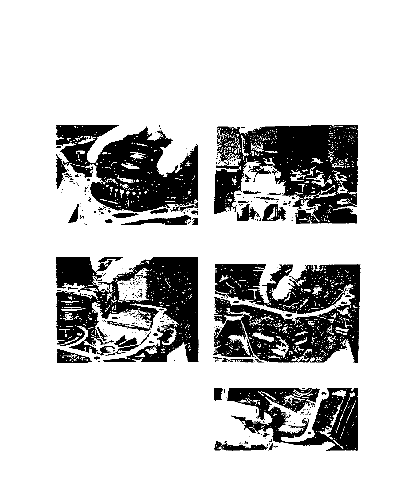
1. )- Rotate crankshaft until piston is at top dead center (TlX:) of its
compression stroke.
2. )- Insert valves in their guides and hold them firmly on their seats.
3. )- Chock clearance with feeler gauge« Use a metric feeler gauge be
tween valve .stem and tappet. Correct clearance is 0.1 mm plus 0.05
mm. minus 0.
i)fcCTIUW 3.3.3- REASSEMBLY
3« 3« 3.1-Tiista11 counterbalance as
sembly over its shaft in engine
gear cover.
3.3.3.3-Install oil stopper into
gear cover. Tighten bolts to 90110 inch-pounds.
3.3.3.2-InstaIl counterbalance co
ver. Retain with 4 bolts and lockwashers. Tighten bolts to 90-110
inch-pounds.
3. 3. 3.4-Instan governor shaft as
senbly. Retain with spring clip.
3.3.3.5-Install oil stopper into
cylinder block, lighten bolts to
90-110 inch-pounds.
3.3-8
Page 79
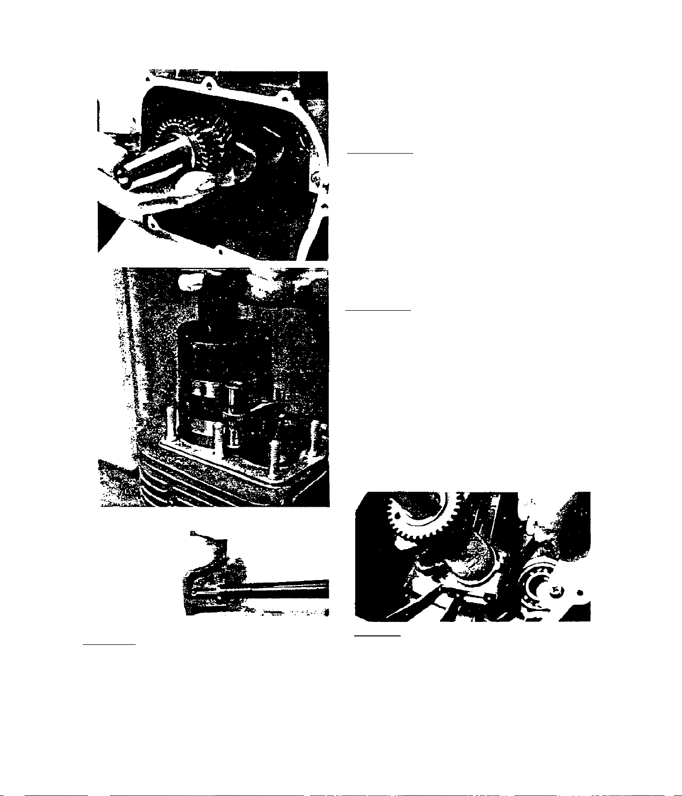
3# 3# 3# 6-Install crankshaft end
play shims. Install crankshaft. Use
care not to damage oil seal and
bearing#
3# 3# 3« 7-Install rings onto piston#
Ring end gaps should be staggered.
See Section 3.3.2, INSPECTION AND
REPAIR, for proper ring locations
In piston grooves. Slide conuectiiig
rod with piston installed do^^
through cylinder until rings contact
top of cylinder block. Then use ring
compressor to compress rings Into
piston grooves. With rings compress
ed, tap piston into cylinder. While
tapping, align connecting rod with
crankshaft. When rings are engaged
by cylinder, remove ring compressor.
3* 3« 3« 8-Connecting rod and connect
ing rod cap are a matched set and
must be replaced as a set. Mark on
cap (see above) must align with id
entical mark on connecting rod dur
ing installation#
3.3.3.9-Lubricate bearing surfaces
of connecting rod and cap. Install
connecting rod cap, oil splasher,
and lock tab onto connecting rod.
Retain with connecting rod bolts.
Use torque wrench and tighten bolts
to 18 - 22 foot-pounds. Bend ends of
lock tab over bolt heads.
3.3-9
Page 80

3.3«3>lO-TnsLa11 tappets*
3.3« 3*11-Install cam shaft* Be
careful not to damage bearing and
oil seal* Timing mark on valley
of crankshaft gear must align
\-ri-th timing mark on tooth of caiii-
shafL gear*
3*3*3*12-InsCall thrust washer
over end of camshaft.
3.3» 3.14-Install one of the long
er bolts that retained the engine
gear cover into the counterbalan
ce alignment hole in gear cover*
Rotate counterbalance while thre
ading bolt into alignment hole.
When holt engages hole in count
erbalance and counterbalance vd.ll
not rotate, tighten bolt no furth
er*
3.3-10
3* 3* 3*13-Bcfore the engine gear
cover can be installed, crank
shaft must be tui.*ned to place
its keyway at 12:00 position
(top dead center of piston)*
Page 81

3» .1, 3« 1 5-Insfa 11 a new gear cover
gasket*
if
a
3.3* 3*17-Install the correct
bolt and fiat washer into count
erbalance alignment hole* USE
THE COEUIECT BOLT - if bolt is Coo
long, dainagp to counterbalance
will result.
3.3.3*16-Align dowel pin on cyl'
inder block with dowel pin hole
on engine gear cover. Install
gear cover. When cover is flush
against cylinder block, remove
bolt from counterbalance align-
ment hole.
3.3.3.18-Retaln engine gear cover
to cyiinder block with bolts and
lockwashers. Tighten all bolts to
00-110 inch-pounds.
3,3,3*19-Tnstall upper and lower
valve spring retainers over ends
of valve springs. Keep intake and
exhaust valve parts together as a
set. See illustration for correct
retainer locations.
3.3-11
Page 82

3« 3> 3» 20-Install springs and ret
ainers over tappets. Intake valve
is identified by the letter ”1",
exhaust valve by an Slide
both velves dovzn through valve
guides, retainers and springs.
3.3.3.21-Compress valve springs,
using a spring compressor. Then
instali roil pin through hole in
valve stem. Remove compressor
and make sure roll pin is locked
in place by lower valve spring
retainer.
•:4 '
'i-
3.3.3.22-Install a new cylinder
head gasket. Install cylinder
head. Location of 4 longer stud
nuts and torque sequence are
shown in illustration.
3. 3. 3. 24-Install cowling,
3.3-12
3.3.3.23-Tlghten head nuts Co 22
29 foot-pounds in sequence shown
in previous illustration.
Page 83

3.3.3> 25-InsCall new intake mani
fold elbow gasket- Install Intake
manifold elbow.
3,3-3,26-Instail spark plug. Cap
should he set to O.Ol^ Inch. Tor
que spark plug to 18-22 foot
pounds .
3.3.3.27-lnstall breather assembly.
Tighten bolts to 90-110 inch-pounds
3«3#3.28-Install engine onto alter
nator slide pan.
3.3-13
 Loading...