

Page 1
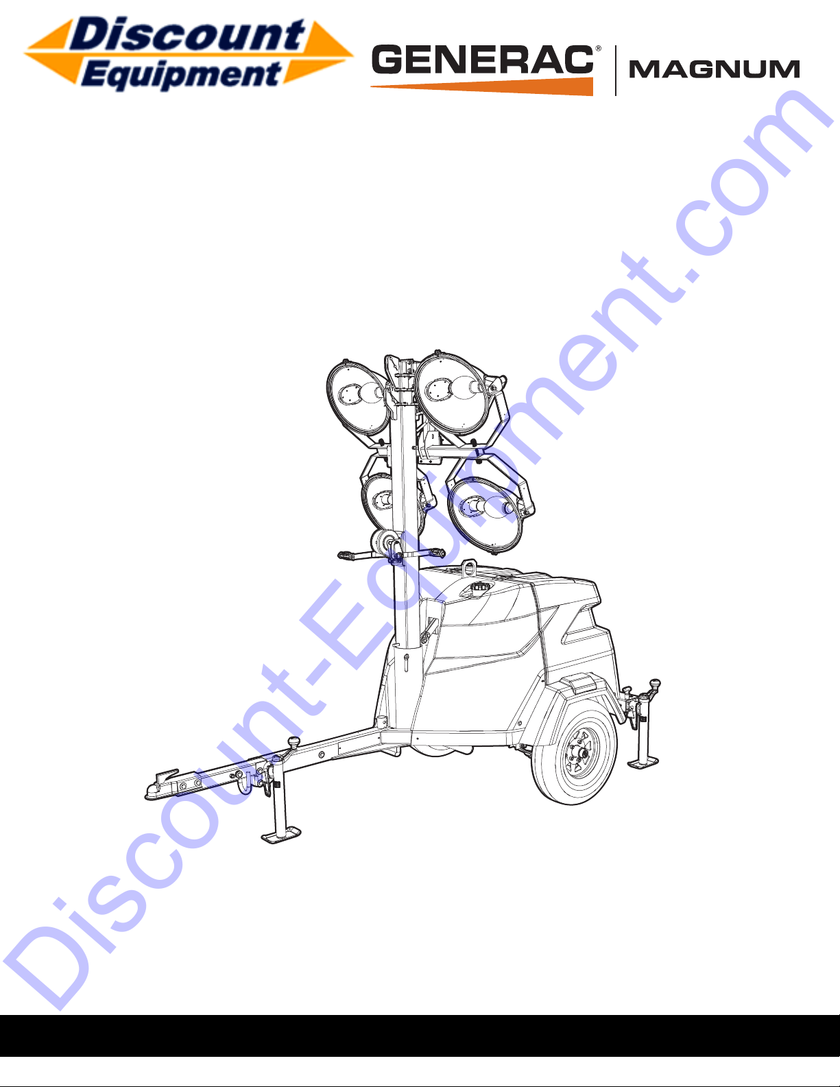
www.discount-equipment.com
Discount-Equipment.com
Owner’s Manual
Light Tower
MLT6SC
006446
######
SA VE THIS MANUAL FOR FUTURE REFERENCE
Page 2

Discount-Equipment.com is your online resource for commercial and industrial
Discount-Equipment.com
quality parts and equipment sales.
Locations:
Florida (West Palm Beach): 561-964-4949
Outside Florida TOLL FREE: 877-690-3101
Need parts? Check out our website at www.discount-equipment.com
Can’t find what you need?
Click on this link: http://www.discount-equipment.com/category/5443-parts/ and fill out
the request form.
Please have the machine model and serial number available in order to help us get
you the correct parts. One of our experienced staff members will get back to you with
a quote for the right part that your machine needs.
We sell worldwide for the br
Diamond
Chicago Pneumatic, Allmand Brothers, Essick, Miller Spreader, Skyjack, Lull, Skytrak,
Tsurumi, Husquvarna/Target, Whiteman-Concrete/Mortar, Stow-Concrete/Mortar, Baldor,
Wacker, Sakai, Snorkel, Upright, Mi-T-M, Sullair, Neal, Basic, Dynapac, MBW, Weber,
Bartell, Bennar Newman, Haulotte, Ditch Runner, Blaw-Knox, Himoinsa, Best, Buddy,
Crown, Edco, Wyco, Bomag, Laymor, Terremite, Barreto, EZ Trench, Takeuchi, Basic, Bil-
Jax, Curtis, Gehl, Heli, Honda, ICS/PowerGrit, Puckett, Waldon, ASV, IHI, Partner, Imer,
Clipper, MMD, Koshin, Rice, Gorman Rupp, CH&E, Cat Pumps, Comet, General Pump,
Giant,AMida, Coleman, NAC, Gradall, Square Shooter, Kent, Stanley, Tamco, Toku, Hatz,
Kohler, Robin, Wisconsin, Northrock, Oztec, Toker TK, Rol-Air, Small Line, Wanco, Yanmar
Products, Magnum, Airman, Mustang, Power Blanket, Nifty Lift, Atlas Copco,
ands: Genie, Terex, JLG, MultiQuip, Mayco, Toro/Stone,
Page 3
Use this page to record important information about your Light Tower
(000393)
WARNING
Operating, servicing and maintaining this
equipment can expose you to chemicals
including engine exhaust, carbon monoxide,
phthalates, and lead, which are known to the
State of California to cause cancer and birth
defects or other reproductive harm. To
minimize exposure, avoid breathing exhaust,
do not idle the engine except as necessary,
service your equipment in a well-ventilated
area and wear gloves or wash your hands
frequently when servicing your equipment.
For more information go to
www.P65Warnings.ca.gov.
(000394)
WARNING
Breathing diesel engine exhaust exposes you
to chemicals known to the State of California
to cause cancer and birth defects or other
reproductive harm.
• Always start and operate the engine in a
well-ventilated area.
• If in an enclosed area, vent the exhaust to
the outside.
• Do not modify or tamper with the exhaust
system.
• Do not idle the engine except as necessary.
For more information go to
www.P65Warnings.ca.gov/diesel.
Discount-Equipment.com
Record the information found on your unit data label on this
Unit Model Number
Unit Serial Number
Engine Model
Number
Engine Serial
Number
Generator Model
Number
Generator Serial
Number
MLT6SC
C1.1—EJ501-2055
201CSA5412
page. See Unit Serial Number Locations.
Engine and generator serial numbers are located on separate
data plates affixed to the engine and generator respectively.
When contacting a Generac Mobile Products Authorized
Service Dealer (GMP ASD) about parts and service, always
provide the unit model and serial number.
Operation and Maintenance: Proper maintenance and care of
the light tower ensures a minimum number of problems and
keeps operating expenses at a minimum. It is the operator’s
responsibility to perform all safety checks, to verify that all
maintenance for safe operation is performed promptly, and to
have the equipment checked periodically by a Generac Mobile
Products Authorized Dealer. Normal maintenance, service and
replacement of parts are the responsibility of the owner/
operator and, as such, are not considered defects in materials
or workmanship within the terms of the warranty. Individual
operating habits and usage may contribute to the need for
additional maintenance or service.
ii Owner’s Manual for MLT6SC Light Tower
Page 4

Table of Contents
Discount-Equipment.com
Section 1: Introduction and Safety
Introduction ..........................................................1
Read This Manual Thoroughly ....................................1
How to Obtain Service .................................................1
Safety Rules .........................................................1
General Hazards ..................................................2
Explosion and Fire Hazards ................................2
Trailer Hazards .....................................................2
Electrical Hazards ................................................3
Battery Hazards ...................................................3
Fuel Hazards ........................................................4
Engine Safety .......................................................4
Operating Safety ..................................................4
Positioning the Unit .....................................................4
Starting the Unit ...........................................................4
Raising and Lowering the Mast ...................................5
Service Safety ......................................................5
Section 3:Operation
Light Tower Setup .............................................25
Prestart Checklist ..............................................26
Raising the Mast—Manual Winch .................... 26
Raising the Mast—Electric Winch (If Equipped)
.............................................................................27
Starting the Unit ................................................28
Preparing for Start-Up (with Power Zone Control-
ler, If Equipped) .................................................29
Select AUTO or MANUAL Mode ...............................29
Manually Starting the Unit ................................29
Light Operation ..................................................29
Light Operation (With Power Zone Controller, If
Equipped) ........................................................... 30
Engine Derating .................................................30
Wet Stacking ......................................................30
Dusk to Dawn Sensor .......................................31
Towing Safety ......................................................6
Hitch and Coupling ......................................................6
Running Lights ............................................................6
Wheels and Tires ........................................................6
Safe Towing Techniques .............................................6
Reporting Trailer Safety Defects ........................6
Safety and Operating Decals ..............................7
Section 2: General Information
Specifications ....................................................11
Unit Serial Number Locations ..........................12
Trailer Tongue Storage and Tow Positions .....13
Place Trailer Tongue in Tow Position ........................13
Place Trailer Tongue in Storage Position ..................14
Unit Dimensions ................................................15
Component Locations .......................................16
Control Panel .....................................................18
Control Panel Features and Functions ......................18
Customer Convenience Outlets .......................31
Shutting Down the Unit .....................................31
Shutting Down the Unit (with Power Zone Con-
troller, If Equipped) ...........................................31
Automatic Shutdown .................................................31
Lower Radiator Hose Heater (If Equipped) .....31
Tandem Tow (If Equipped) ............................... 32
Telemetry (If Equipped) ....................................32
Spark Arrester (If Equipped) ............................ 32
Lowering the Mast—Manual Winch ................. 32
Lowering the Mast—Electric Winch
(If Equipped) ......................................................33
Manually Lowering the Mast ...................................... 33
Towing the Unit .................................................33
Lifting the Unit ...................................................34
Tying the Unit Down ..........................................34
Power Zone–DLA (If Equipped) ........................19
Controller Features and Functions ............................19
Operator Screens ......................................................20
Owner’s Manual for MLT6SC Light Tower iii
Page 5

Section 4:Maintenance
Discount-Equipment.com
Emissions Information ......................................35
Daily Walk-Around Inspection ..........................35
General Maintenance .........................................35
Preparing for Service ................................................ 35
Cleaning the Unit ...................................................... 35
Inspecting the Unit .................................................... 35
Basic Maintenance Schedule ...........................36
Resetting the Maintenance Alarms
(If Equipped) .......................................................38
Manual Winch: Use, Operation, and
Maintenance .......................................................38
Prior to Use ............................................................... 38
Operation .................................................................. 38
Maintenance ............................................................. 38
Electric Winch: Use, Operation, and
Maintenance .......................................................38
Winch Mechanical Brake .......................................... 39
Jack Maintenance ..............................................39
Trailer Wheel Bearings ......................................39
Section 5:Troubleshooting
General Troubleshooting ..................................41
Troubleshooting the Lights ..............................42
Section 6:Wiring Diagrams
Mast Junction Box Wiring and Light
Connections .......................................................43
AC Wiring Diagram ............................................44
DC Wiring Diagram ............................................45
DC Wiring - Electric Winch Option ...................46
Trailer Lights Wiring ..........................................47
Section 7:Service Log
iv Owner’s Manual for MLT6SC Light Tower
Page 6
Section 1: Introduction and Safety
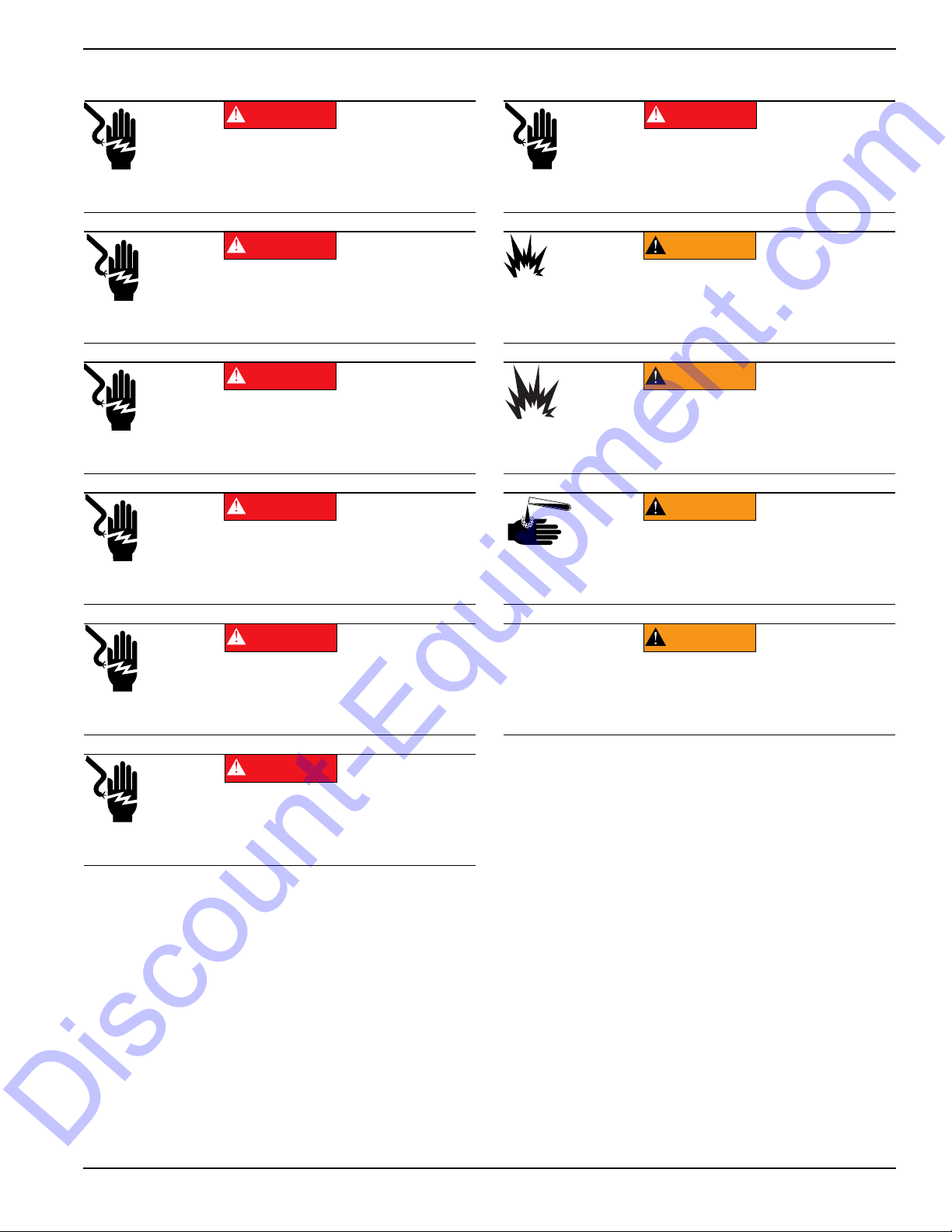
(000100a)
WARNING
Consult Manual. Read and understand manual
completely before using product. Failure to
completely understand manual and product
could result in death or serious injury.
(000001)
DANGER
Indicates a hazardous situation which, if not avoided,
will result in death or serious injury.
(000002)
WARNING
Indicates a hazardous situation which, if not avoided,
could result in death or serious injury.
(000003)
CAUTION
Indicates a hazardous situation which, if not avoided,
could result in minor or moderate injury.
Discount-Equipment.com
Introduction and Safety
Introduction
Thank you for purchasing a Generac Mobile Products LLC
product. This unit has been designed to provide high
performance, efficient operation, and years of use when
maintained properly.
The information in this manual is accurate based on
products produced at the time of publication. The
manufacturer reserves the right to make technical updates,
corrections, and product revisions at any time without
notice.
Read This Manual Thoroughly
If any section of the manual is not understood, contact your
nearest Generac Mobile Products Authorized Service
Dealer with any questions or concerns.
The owner is responsible for proper maintenance and safe
use of the equipment. Comply with regulations the
Occupational Safety and Health Administration (OSHA)
has established, or with equivalent standards. Also, verify
that the unit is applied, used, and maintained in accordance
with the manufacturer's instructions and recommendations.
Do nothing that might alter safe application/usage and
render the unit in noncompliance with the aforementioned
codes, standards, laws, and regulations
Save these instructions for future reference. This manual
contains important instructions for the unit that should be
followed during setup, operation and maintenance of the
unit and battery. ALWAYS supply this manual to any
individual that will use this machine.
.
Safety Rules
The manufacturer cannot anticipate every possible
circumstance that might involve a hazard. The warnings in
this manual, and on tags and decals affixed to the unit are,
therefore, not all inclusive. If using a procedure, work
method or operating technique that the manufacturer does
not specifically recommend, verify that it is safe for others.
Also make sure the procedure, work method or operating
technique utilized does not render the equipment unsafe.
Throughout this publication, and on tags and decals affixed
to the unit, DANGER, WARNING, CAUTION and NOTE
blocks are used to alert personnel to special instructions
about a particular operation that may be hazardous if
performed incorrectly or carelessly. Observe them
carefully. Their definitions are as follows:
How to Obtain Service
When the unit requires servicing or repairs, contact a GMP
ASD for assistance. Service technicians are factory-trained
and are capable of handling all service needs. For
assistance locating a dealer, go to
www.generacmobleproducts.com/parts-service/find-
service. When contacting a Generac Mobile Products
Authorized Service Dealer about parts and service, always
supply the complete model number and serial number of
the unit as given on its data decal located on the unit.
Record the model number and serial numbers in the
spaces provided on the inside front cover of this manual.
Owner’s Manual for MLT6SC Light Tower 1
NOTE: Notes contain additional information important to
a procedure and will be found within the regular text of
this manual.
These safety alerts cannot eliminate the hazards that they
indicate. Common sense and strict compliance with the
special instructions while performing the action or service
are essential to preventing accidents.
Page 7
Introduction and Safety
Asphyxiation. Running engines produce
carbon monoxide, a colorless, odorless,
poisonous gas. Carbon monoxide, if not
avoided, will result in death or serious injury.
(000103)
DANGER
(000107)
WARNING
Hearing Loss. Hearing protection is
recommended when using this machine.
Failure to wear hearing protection could
result in permanant hearing loss.
(000111)
WARNING
Moving Parts. Keep clothing, hair, and
appendages away from moving parts. Failure
to do so could result in death or serious injury.
(000108)
WARNING
Hot Surfaces. When operating machine, do not
touch hot surfaces. Keep machine away from
combustibles during use. Hot surfaces could
result in severe burns or fire.
WARNING
Risk of injury. Do not operate or service this machine
if not fully alert. Fatigue can impair the ability to service
this equipment and could result in death or serious
injury.
(000215)
(000139)
WARNING
Risk of burns. Allow engine to cool before
draining oil or coolant. Failure to do so could
result in death or serious injury.
(000105)
DANGER
Explosion and Fire. Fuel and vapors are
extremely flammable and explosive. Add fuel
in a well ventilated area. Keep fire and spark
away. Failure to do so will result in death
or serious injury.
(000147)
WARNING
Risk of Fire. Unit must be positioned in a
manner that prevents combustible material
accumulation underneath. Failure to do so
could result in death or serious injury.
(000110)
WARNING
Risk of Fire. Hot surfaces could ignite
combustibles, resulting in fire. Fire could
result in death or serious injury.
WARNING
Personal injury. Trailer must be securely coupled to
the hitch with the chains correctly attached. Uncoupled
or unchained towing could result in death or serious
injury.
(000233a)
Personal injury. Do not operate unit during transport.
Doing so could result in death, serious injury, or
property damage.
(000231a)
WARNING
(000234a)
WARNING
Crushing hazard. Verify unit is properly secured and
on level ground. An unsecured unit can suddenly roll
or move, causing death or serious injury.
WARNING
Property or Equipment Damage. Tighten wheel lug
nuts after first 50 miles to factory specifications.
Failure to do so could result in death, serious injury,
property or equipment damage.
(000235)
Discount-Equipment.com
General Hazards
Explosion and Fire Hazards
Trailer Hazards
2 Owner’s Manual for MLT6SC Light Tower
Page 8
Electrical Hazards Battery Hazards
(000145)
DANGER
Electrocution. In the event of electrical accident,
immediately shut power OFF. Use non-conductive
implements to free victim from live conductor. Apply
first aid and get medical help. Failure to do so will
result in death or serious injury.
(000104)
DANGER
Electrocution. Water contact with a power
source, if not avoided, will result in death
or serious injury.
(000144)
DANGER
Electrocution. Contact with bare wires,
terminals, and connections while generator
is running will result in death or serious injury.
(000152)
DANGER
Electrocution. Verify electrical system is
properly grounded before applying power.
Failure to do so will result in death or serious
injury.
(000188)
DANGER
Electrocution. Do not wear jewelry while
working on this equipment. Doing so will
result in death or serious injury.
DANGER
Electrocution. DO NOT use the unit if
electrical cord is cut or worn through. Doing
so will result in death or serious injury.
(000263a)
(000188)
DANGER
Electrocution. Do not wear jewelry while
working on this equipment. Doing so will
result in death or serious injury.
(000137a)
WARNING
Explosion. Batteries emit explosive gases while charging.
Keep fire and spark away. Wear protective gear when
working with batteries. Failure to do so could result in
death or serious injury.
(000162)
WARNING
Explosion. Do not dispose of batteries in a fire. Batteries
are explosive. Electrolyte solution can cause burns and
blindness. If electrolyte contacts skin or eyes, flush with water
and seek immediate medical attention.
(000163a)
WARNING
Risk of burn. Do not open or mutilate batteries.
Batteries contain electrolyte solution which can
cause burns and blindness. If electrolyte contacts
skin or eyes, flush with water and seek immediate
medical attention.
WARNING
Environmental Hazard. Always recycle batteries at an
official recycling center in accordance with all local
laws and regulations. Failure to do so could result in
environmental damage, death or serious injury.
(000228)
Discount-Equipment.com
Introduction and Safety
Owner’s Manual for MLT6SC Light Tower 3
Always recycle batteries in accordance with local laws and
regulations. Contact your local solid waste collection site
or recycling facility to obtain information on local recycling
processes. For more information on battery recycling, visit
the Battery Council International website at: http://
batterycouncil.org
Page 9
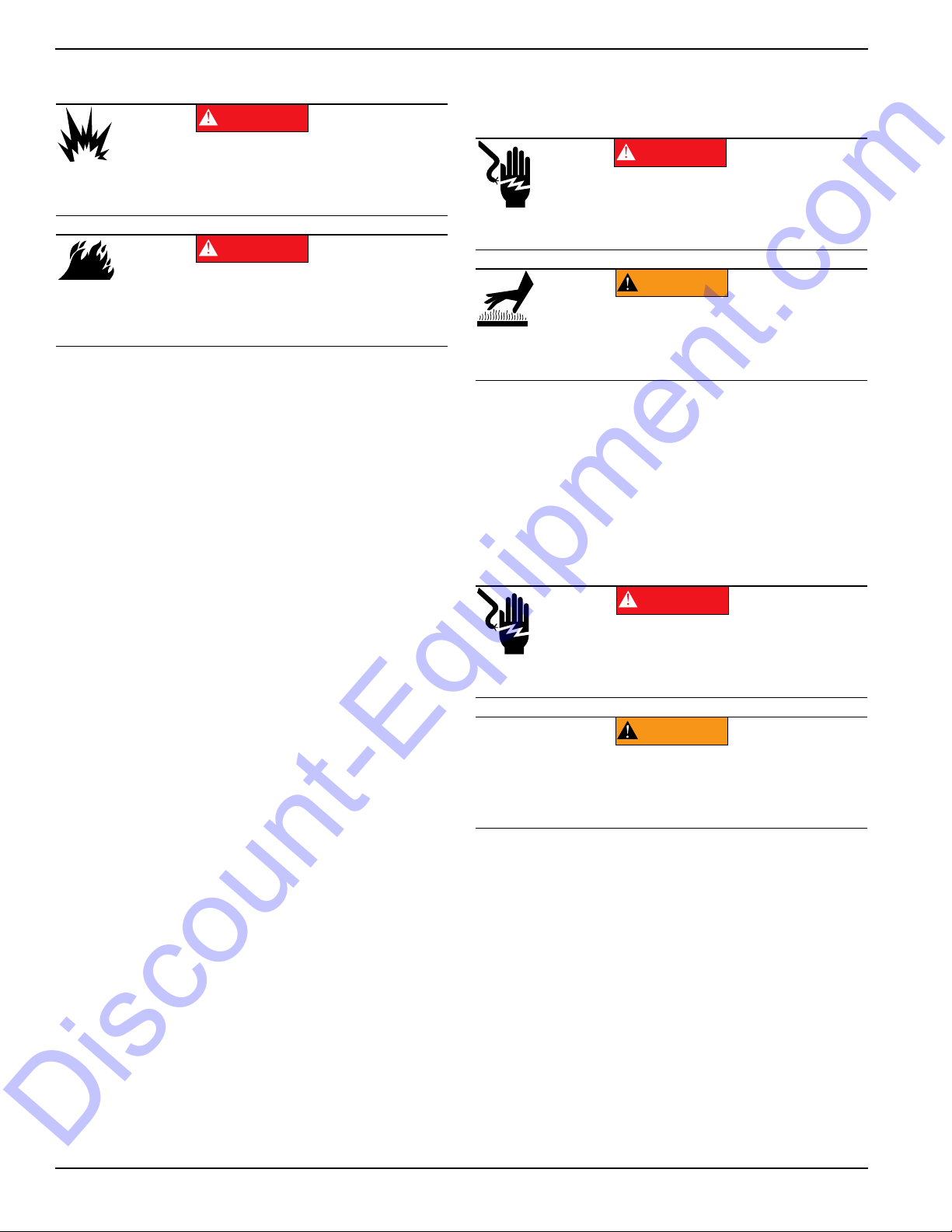
Introduction and Safety
(000192)
DANGER
Explosion and fire. Fuel and vapors are extremely
flammable and explosive. No leakage of fuel is
permitted. Keep fire and spark away. Failure to do
so will result in death or serious injury.
(000174)
DANGER
Risk of fire. Allow fuel spills to completely dry
before starting engine. Failure to do so will
result in death or serious injury.
(000260a)
High Voltage. Verify area above unit is clear
of overhead wires and obstructions. Contact
with high-voltage power lines will result in
death or serious injury.
DANGER
(000277)
WARNING
Burn hazard. Never operate lights with a
damaged or missing lens cover. Lamps are
hot and pressurized while in use. Unprotected
lamps can shatter, causing severe injury.
DANGER
Electrocution. DO NOT use the unit if
electrical cord is cut or worn through. Doing
so will result in death or serious injury.
(000263a)
CAUTION
(000291)
Equipment damage. Do not attempt to start or operate
a unit in need of repair or scheduled maintenance.
Doing so could result in serious injury, death, or
equipment failure or damage.
WARNING
Discount-Equipment.com
Fuel Hazards
• DO NOT fill fuel tank near an open flame, while
smoking, or while engine is running. DO NOT fill
tank in an enclosed area with poor ventilation.
• DO NOT operate with the fuel tank cap loose or
missing.
Engine Safety
Internal combustion engines present special hazards
during operation and fueling. Failure to follow the safety
guidelines described below could result in severe injury or
death. Read and follow all safety alerts described in the
engine operator's manual. A copy of this manual was
supplied with the unit when it was shipped from the factory.
Operating Safety
Positioning the Unit
The area immediately surrounding the unit should
•
be dry, clean, and free of debris.
• Position and operate the unit on a firm, level
surface.
• If the unit is equipped with a frame grounding stud,
follow the National Electrical Code (NEC), state,
and local regulations when connecting.
Starting the Unit
• DO NOT run engine indoors or in an area with poor
ventilation. Make sure engine exhaust cannot seep
into closed rooms or ventilation equipment.
• DO NOT clean air filter with gasoline or other types
of low flash point solvents.
• DO NOT operate the unit without a functional
exhaust system.
• Shut the engine down if any of the following
conditions exist during operation:
• Noticeable change in engine speed.
• Loss of electrical output.
• Equipment connected to the unit overheats.
• Sparking occurs.
• Engine misfires or there is excessive engine/
generator vibration.
• Protective covers are loose or missing.
• Ambient air temperature is above 120°F (49°C).
4 Owner’s Manual for MLT6SC Light Tower
Page 10
Introduction and Safety
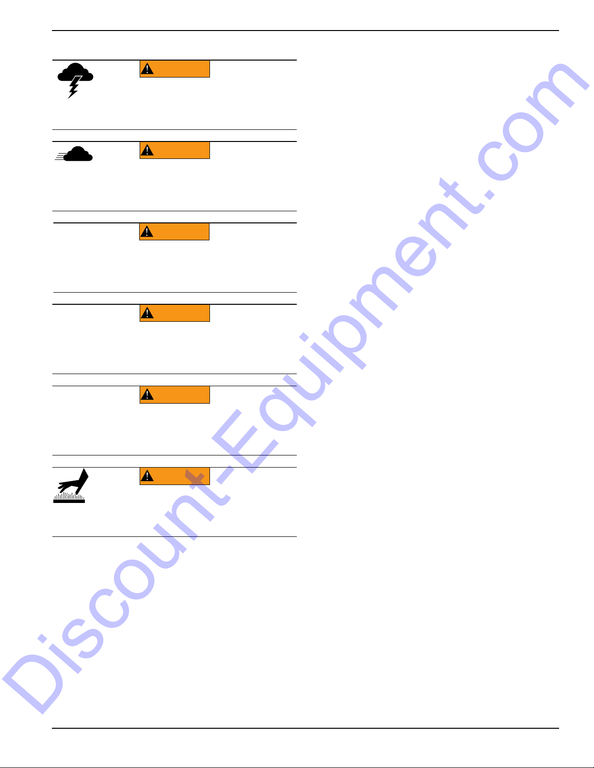
WARNING
Electrocution. Do not set up or operate
this unit if severe weather is expected.
Lightning strikes can kill or cause severe injury
even if you are not touching the unit.
(000296)
WARNING
(000297)
> 60 mph> 60 mph
Do not set up the unit if high winds
are expected. High winds can cause the
unit to tip or fall, causing severe injury
or machine damage.
(000279)
Personal injury or equipment damage. Do not raise
or lower the mast while the unit is operating.
Doing so can break the lenses and cause the
lamps to shatter.
WARNING
WARNING
Personal Injury. Stop immediately if the mast hangs
up or the winch cable develops slack. Excess slack
could cause the mast to collapse, resulting in personal
injury or equipment damage.
(000265)
WARNING
Tipping hazard. Extend the outriggers and level the unit
before raising the mast. Keep the outriggers extended
while the mast is up. Failure to do so could cause the unit
to tip and fall and could result in death or serious injury.
(000266)
(000278)
WARNING
Burn hazard. Lamps become extremely hot
while in use. Allow 10–15 minutes for cooling
before handling or lowering mast. Touching a
hot lens or fixture can cause severe burns.
Discount-Equipment.com
Raising and Lowering the Mast
Service Safety
This unit uses high voltage circuits capable of causing
serious injury or death. Only a qualified and licensed
electrician should troubleshoot or repair problems
occurring in this equipment.
•
Before servicing the unit, verify the Control Power
switch and circuit breakers are in the OFF (O)
position, and the negative (-) terminal on the battery
is disconnected.
service (oil/filter changes, cleaning, etc.) unless all
electrical components are shut down.
•
ALWAYS
unit in damp conditions. Do not service the unit if your
skin or clothing is wet. Do not allow water to collect
around the base of the unit.
•
DO NOT
power washers, or steam cleaners. Water may
collect in the unit, causing damage to electrical parts.
•
Replace all missing and hard to read decals. Decals
provide important operating instructions and warn of
dangers and hazards.
•
Wear heavy leather gloves when handling winch
cables. Never let cables slip through bare hands.
•
Only use mild soap and water to clean the lens covers.
Other chemicals may damage the lens covers.
use extreme caution when servicing this
wash the unit with high pressure hoses,
DO NOT
perform even routine
Keep area around the unit clear of people while
•
raising and lowering the mast.
• ALWAYS lower the mast when not in use.
• The tower extends up to 23 ft (7 m). Verify area
above trailer is open and clear of overhead wires
and obstructions.
• If for any reason any part of mast hangs up or
winch cable develops slack while raising or
lowering tower, STOP immediately! Contact a
Generac Mobile Products Authorized Service
Dealer.
• NEVER remove safety pin or pull mast locking pin
while tower is up.
Owner’s Manual for MLT6SC Light Tower 5
Page 11

Introduction and Safety
Discount-Equipment.com
Towing Safety
Towing a trailer requires care. Both the trailer and vehicle
must be in good condition and securely fastened to each
other to reduce the possibility of an accident. Some states
require that large trailers be registered and licensed.
Contact your local Department of Transportation office to
check on license requirements for your particular unit.
Hitch and Coupling
Verify the hitch and coupling on the towing vehicle
•
are rated equal to, or greater than, the trailer's
Gross Vehicle Weight Rating (GVWR).
• Verify the trailer hitch and the coupling are
compatible. Make sure the coupling is securely
fastened to the vehicle.
• DO NOT tow trailer using defective parts. Inspect
the hitch and coupling for wear or damage.
• Connect safety chains in a crossing pattern under
the tongue.
• Before towing the trailer, verify that the weight of
the trailer is equal across all tires. On trailers with
adjustable height hitches, adjust the angle of the
trailer tongue to keep the trailer as level as
possible.
Reporting Trailer Safety Defects
If you believe your trailer has a defect which could cause
a crash or could cause injury or death, you should
immediately inform the National Highway Traffic Safety
Administration (NHTSA) in addition to notifying Generac
Mobile Products LLC.
If NHTSA receives similar complaints, it may open an
investigation; and if it finds that a safety defect exists in a
group of vehicles, it may order a recall and remedy
campaign. However, NHTSA cannot become involved in
an individual problem between you, your dealer, or
Generac Mobile Products LLC.
To contact NHTSA, you may either call the Auto Safety
Hotline toll-free at 1-888-327-4236 (TTY:1-800-424-9153),
go to http://www.safercar.gov; or write to:
Administrator
NHTSA
1200 New Jersey Avenue S.E.
Washington, DC 20590
You can also obtain other information about motor vehicle
safety from http://www.safercar.gov.
Running Lights
Verify directional and brake lights on the trailer are
connected and working properly
Wheels and Tires
•
Check trailer tires for wear and proper inflation.
• Verify wheel lug nuts are present and tightened to
the specified torque.
Safe Towing Techniques
Practice turning, stopping and backing up in an
•
area away from heavy traffic prior to transporting
the unit.
• Maximum recommended speed for highway towing
is 45 mph (72 km/h). Recommended off-road
towing speed is 10 mph (16 km/h) or less,
depending on terrain.
• When towing, maintain extra space between
vehicles and avoid soft shoulders, curbs and
sudden lane changes.
6 Owner’s Manual for MLT6SC Light Tower
Page 12
Introduction and Safety
######
1
SET UP
AUFSTELLUNG
INSTALACIÓN
INSTALLATION
X
2
2
C
B
4
5
6
TAKE DOWN
ABBAU
DESINSTALACIÓN
DÉMONTAGE
15 MIN
STOP
1 3 4
X
2
1 Inch
(25 mm)
x3
3
2
B
A
A
C
SET UP
AUFSTELLUNG
INSTALACIÓN
INSTALLATION
TAKE DOWN
ABBAU
DESINSTALACIÓN
DÉMONTAGE
4
X
2
3
B
A
C
IOI
O
I
O
I
O
15 MIN
STOP
X
2
2
1 Inch
(25 mm)
x3
3
B
4
A C
0°±5°
1
IOI
O
I
O
I
O
STOP
65
1 2
1
2
006447
Discount-Equipment.com
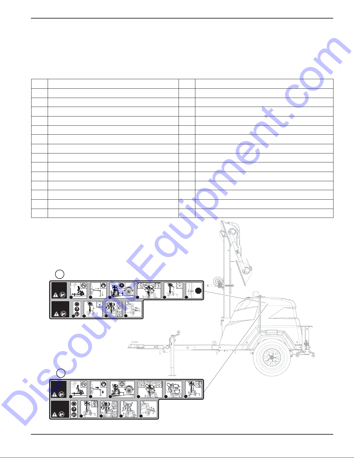
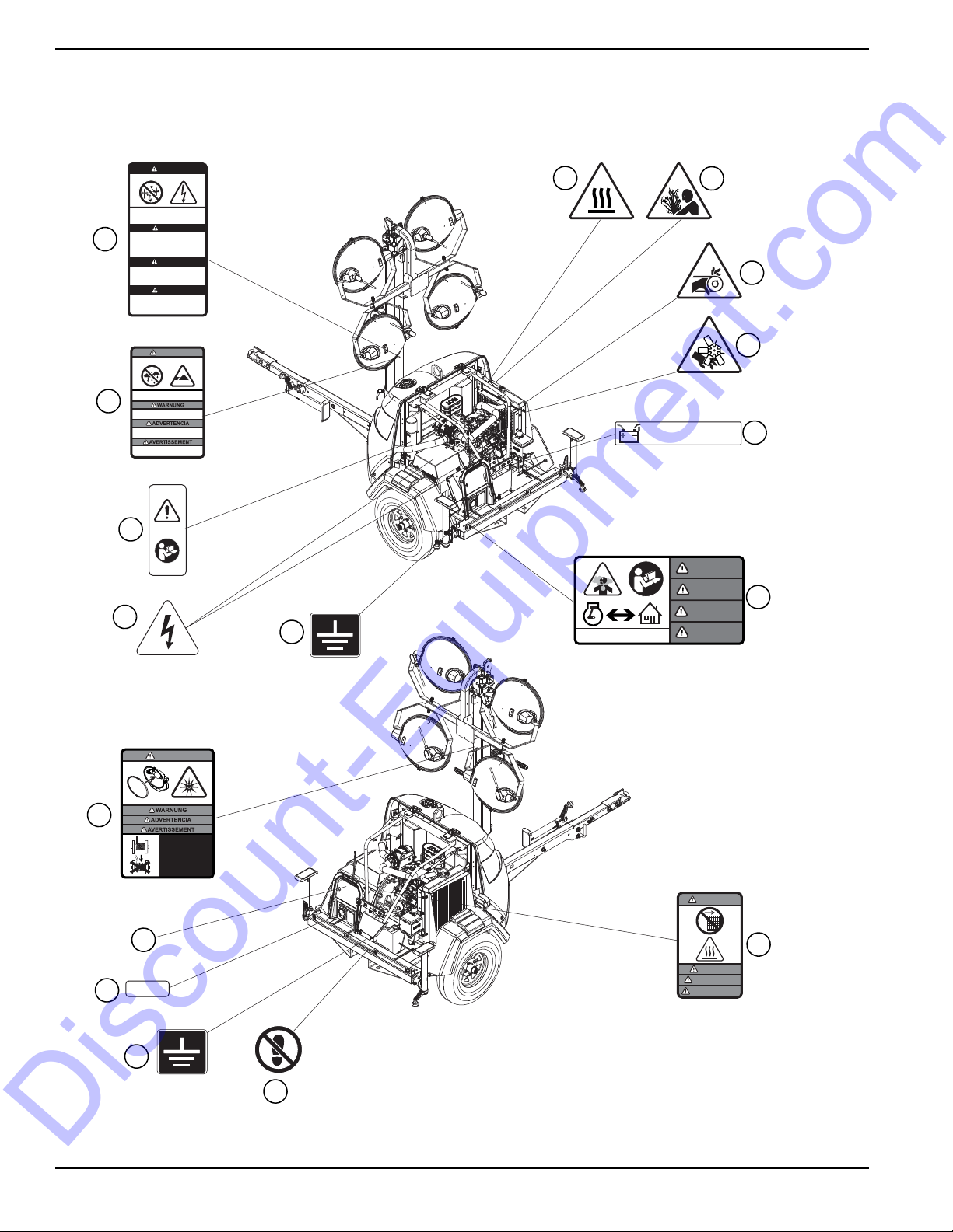
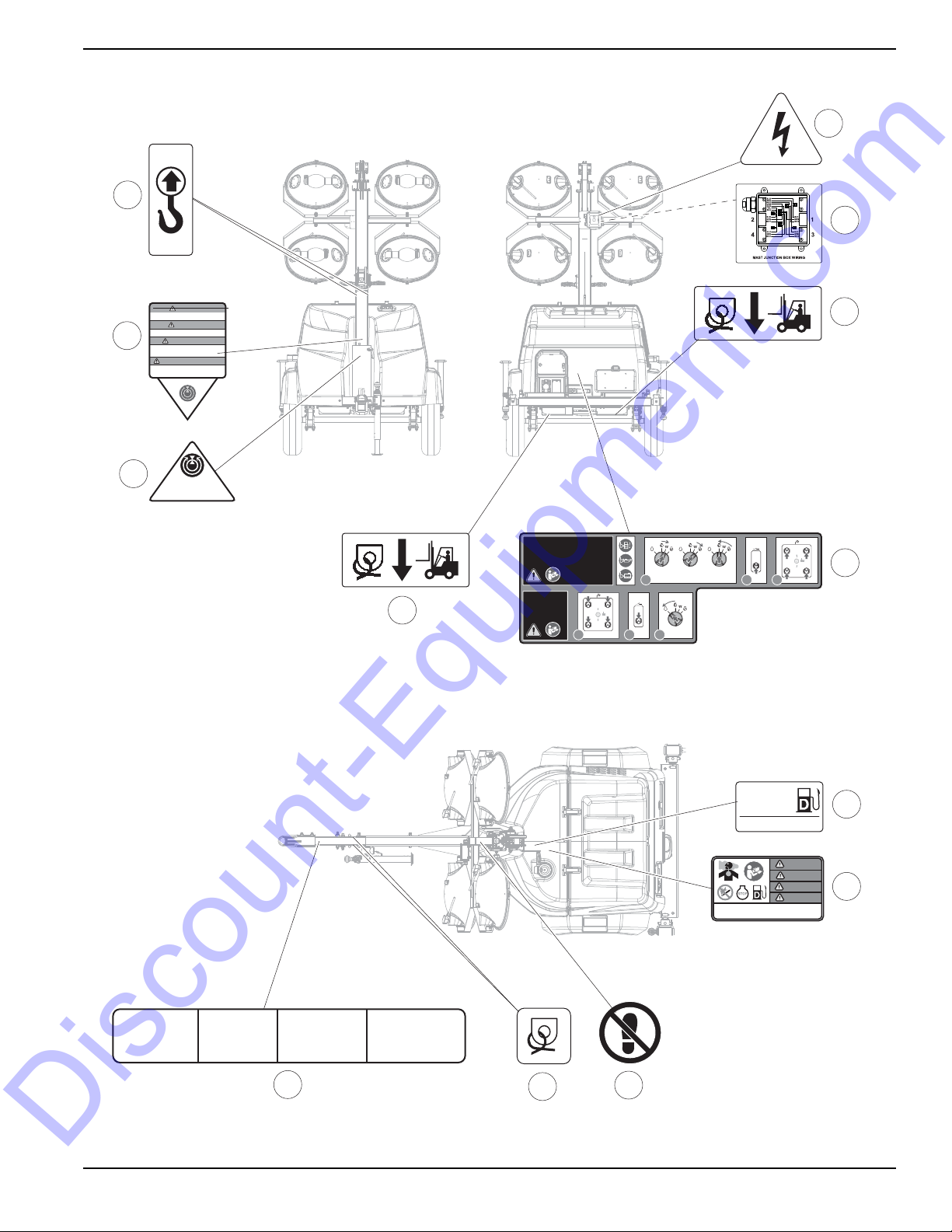
Safety and Operating Decals
See Figure 1-1 through Figure 1-3. This unit features
Replace any missing or hard-to-read decals and use care
when
washing or cleaning the unit. Decal part numbers
can be found in the parts manual.
numerous safety and operating decals. These decals
provide important operating instructions and warn of
dangers and hazards. The following diagrams illustrate
decal locations and descriptions.
ID Description ID Description
1 Setup and Take-Down Instructions (Electric) 15 Control Panel Label (not shown)
2 Setup and Take-Down Instructions (Manual) 16 Neutral Bonded to Frame
3 Danger—Overhead Power Lines 17 Not A Step
4 Warning—Electrical Storms and High Wind 18 Warning—High Temperature: Do Not Remove Guard
5 Owner’s Manual Location 19 Mast Junction Box Wiring (inside)
6 Electric Shock Hazard 20 Warning—Do Not Retract Outriggers With Tower Up
7 Warning—Pressurized Liquid 21 Stowed Position
8 Warning—Hot Surface 22 Lifting Point
9 Warning—Entanglement Hazard 23 Forklift and Tie-Down Point
10 Warning—Cutting Hazard 24 Engine Operation
11 Disconnect Battery Before Servicing 25 Ultra Low Sulfur Diesel Fuel Only
12 Danger—Carbon Monoxide 26 Danger—Fuel and Fueling Hazards
13 Electrical Ground Connection 27 Tie-Down Point
14 Danger—Ultraviolet Radiation / Winch Operation 28 Towing Instructions
0°±5°
Owner’s Manual for MLT6SC Light Tower 7
Figure 1-1. Decal Locations (1 of 3)
Page 13
Introduction and Safety
######
WARNUNG
ADVERTENCIA
AVERTISSEMENT
WARNING
Débrancher la batterie avant de faire l’entretien.
Disconnect battery before servicing.
Vor der Instandsetzung die Batterieverbindungen lösen.
Desconecte la batería
antes de realizar el servicio técnico.
CARBON MONOXIDE
DANGER
GEFAHR
PELIGRO
DANGER
WARNING
NOTICE
HINWEIS
AVI SO
AVI S
Nicht bei Windgeschwindigkeit von mehr
als 95 km/h oder bei Gewitter aufstellen.
No instalar cuando el viento exceda los
95 km/h o durante tormentas eléctricas.
Ne pas installer dans des vents excédant
60 mph ou pendant les orages electriques.
DO NOT set up unit in winds exceeding
60 mph, or during electrical storms.
ELECTRICAL STORMS & HIGH WIND
> 60 mph> 60 mph
WARNING
Der kontakt mit elektrischen
Hochspannungsleitungen kann zu schweren
oder lebensgefährlichen Verletzungen
führen. Den Beleuchtungswagen nie direkt
unter Hochspannungsleitungen aufstellen.
El contacto con las líneas electricas
elevadas podría causar lesiones serias o la
muerte. No posicione la torre de iluminación
debajo de líneas electricas.
Le contact avec des câbles électriques
suspendus causera des blessures graves ou
la mort. Ne pas positionner la tour
lumineuse sous des câbles électriques.
Contact with overhead electrical power lines
will cause serious injury or death. Do not
position light tower under electrical power lines.
OVERHEAD POWER LINES
DANGER
GEFAHR
PELIGRO
DANGER
NEUTRAL BONDED TO FRAME
NULLLEITER AM RAHMEN ANGESCHLOSSEN
NEUTRO CONECTADO AL BASTIDOR
POSITION NEUTRE LORSQUE FIXÉ AU CADRE
3
4
5
6
7
8
9
10
11
12
13
14
15
16
17
18
13
006448
Discount-Equipment.com
Figure 1-2. Decal Locations (2 of 3)
8 Owner’s Manual for MLT6SC Light Tower
Page 14
######
S≤15 mg/kg
ULTRA LOW
SULFUR
FUEL ONLY
1. Read operator's manual.
2. Use hitch rated for trailer's "gross vehicle weight
rating".
3. Securely attach trailer to tow vehicle.
4. Attach safety chains using a cross pattern.
5. Attach breakdown chain to vehicle.
6. Check trailer lights.
TOWING INSTRUCTIONS INSTRUCCIONES PARA REMOLQUE
1. Lea el manual del operador.
2. Use un enganche adecuado para la “capacidad
de peso bruto del vehículo” del remolque.
3. Enganche firmemente el remolque al vehículo
de remolque.
4. Enganche las cadenas de seguridad en
forma cruzada.
5. Enganche al vehículo la cadena de emergencia
para averías.
6. Revise las luces del remolque.
ABSCHLEPPANWEISUNGEN
1. Lire le manuel de l’utilisateur.
2. Utiliser un attelage convenant au poids nominal
brut de la remorque.
3. Arrimer solidement la remorque au véhicule tracteur.
4. Poser les chaînes de sécurité en les croisant.
5. Fixer la chaîne de remorquage au véhicule.
6. Vérifier les feux de la remorque.
INSTRUCTIONS DE REMORQUAGE
1. Benutzerhandbuch lesen.
2. Anhängevorrichtung verwenden, die der
„Gesamtbetriebsgewichtsklasse” des
Fahrzeugs entspricht.
3. Anhänger sicher am
Abschleppfahrzeug befestigen.
4. Sicherheitsketten über Kreuz anbringen.
5. Abreißkette am Fahrzeug anbringen.
6. Anhängerleuchten prüfen.
DANGER
GEFAHR
PELIGRO
DANGER
DIESEL DIESEL
SHUTDOWN
ABSCHALTUNG
APAGADO
ARRÊT
I
O
1 3
MAIN
BREAKER
240V
I
O
2
I
O
IOI
O
STOP
3
ENGINE OPERATION
MOTORBETRIEB
OPERACIÓN DEL MOTOR
FONCTIONNEMENT DU MOTEUR
1
ACTIVATE
GLOW PLUGS
<15 SEC.
CRANK ENGINE
TO START
RELEASE
KEY
MAIN
BREAKER
240V
I
O
32
IOI
O
IOI
O
MANUAL LOCATED
INSIDE HOOD
STOP
STOP
STOP
STOP
Nicht zurückziehen Ausleger mit Turm auf.
No retraiga estabilizadores con la torre de
arriba.
Ne pas retirer les stabilisateurs avec la
tour vers le haut.
DO NOT retract outriggers with tower up.
WARNING
WARNUNG
ADVERTENCIA
ADVERTISSEMENT
21
22
24
23
17
27
28
25
26
20
6
23
19
Stowed Position
Verstauposition
Posición de estibación
Position de rangement
006449
Discount-Equipment.com
Introduction and Safety
Owner’s Manual for MLT6SC Light Tower 9
Figure 1-3. Decal Locations (3 of 3)
Page 15
Section 2: General Information
Discount-Equipment.com
Specifications
DESCRIPTION UNITS MLT6SC
Engine
EPA Tier — Tier 4 Final
Fuel Consumption—100% Prime gph (Lph) 0.74 (2.80)
Battery Type—Group Number — 24
Battery Voltage quantity per unit 12 (1)
Battery Rating cold-cranking
amp-hours
Generator
Output - Standby kW (kVA) 6.0 (6.0)
Output Voltage volts 120/240, single phase
Output Amperes 120V (240V) amperes 20 (25)
Frequency Hz Hertz 60
Weights
Dry Weight lbs (kg) 1316 (597)
Operating Weight lbs (kg) 1586 (719)
Capacities
Fuel Tank Volume gal (L) 40.75 (154.26)
Usable Fuel Volume gal (L) 39.9 (151.04)
Coolant (including engine) qt (L) 5.0 (4.7)
Oil (including filter) qt (L) 4.6 (4.4)
Maximum Run Time hours 59
440
General Information
AC Distribution
Circuit Breaker Size amperes 30
Trailer
Hitch—Standard — 2 in. ball
Maximum Tire Pressure psi (kPA) 50 (345)
Specifications are subject to change without notice.
Owner’s Manual for MLT6SC Light Tower 11
Page 16
General Information
######
VIN Tag
Unit ID Tag
(Located on top of control box)
Serial Number
V
A
Model
KVA
Manufacturing Code
1 ph. 1.0PF 3 ph. .8PF 3 ph. 1.0PF
KW
Country of Origin
Weight (lbs/kg) RPM/Frequency
Rating
Ins. Class
FOR ELECTRICAL EQUIPMENT
ONLY. POUR MATERIAL
ELECTRIQUE SEULEMENT.
209649
Form: SFC626B
Manufactured by Generac Mobile Products LLC
(920) 361-4442 (800) 926-9768
TIRE AND LOADING INFORMATION
RENSEIGNEMENTS SUR LES
PNEUS ET LE CHARGEMENT
SEE OWNER’S
MANUAL FOR
ADDITIONAL
INFORMATION
VOIR LE
MANUEL DE
L’USAGER
POUR
PLUS DE
RENSEIGNEMENTS
MANUFACTURED BY/FABRIQUE PAR: Generac Mobile Products LLC
DATE: 00/0000
GVWR/PNBV: 000KG (0000LBS)
COLD INF. PRESS./
PRESS.DE
V.I.N./N.I.V.:
00000000000000000
TYPE: TRAIL ER
MODEL:
XXX000
GAWR / PNBE TIRE / PNEU RIM / JANTE GONFA FROID - KPA(PSI/LPC) SGL / DUAL
EACH
AXLE
THIS VEHICLE CONFORMS TO ALL APPLICABLE STANDARDS PRESCRIBED UNDER THE U.S. FEDERAL MOTOR VEHICLE SAFETY STANDARDS(FMVSS) AND CANADIAN
MOTOR VEHICLE SAFETY REGULATIONS IN EFFECT ONTHE DATE OF MANUFACTURE.
CE VEHICULE EST CONFORME A TOUTES LES NORMES QUI LUI SONT APPLICABLES EN VERTU DU REGLEMENT SUR LA SECURITE DES VEHICULES AUTOMOBILES
DU CANADA EN VIGUEUR A LA DATE SA FABRICATION.
The weight of cargo should never exceed 0000KG (0000LBS)
Le poids du chargement ne doit jamais depasser 0000KG (0000LBS)
006450
Discount-Equipment.com
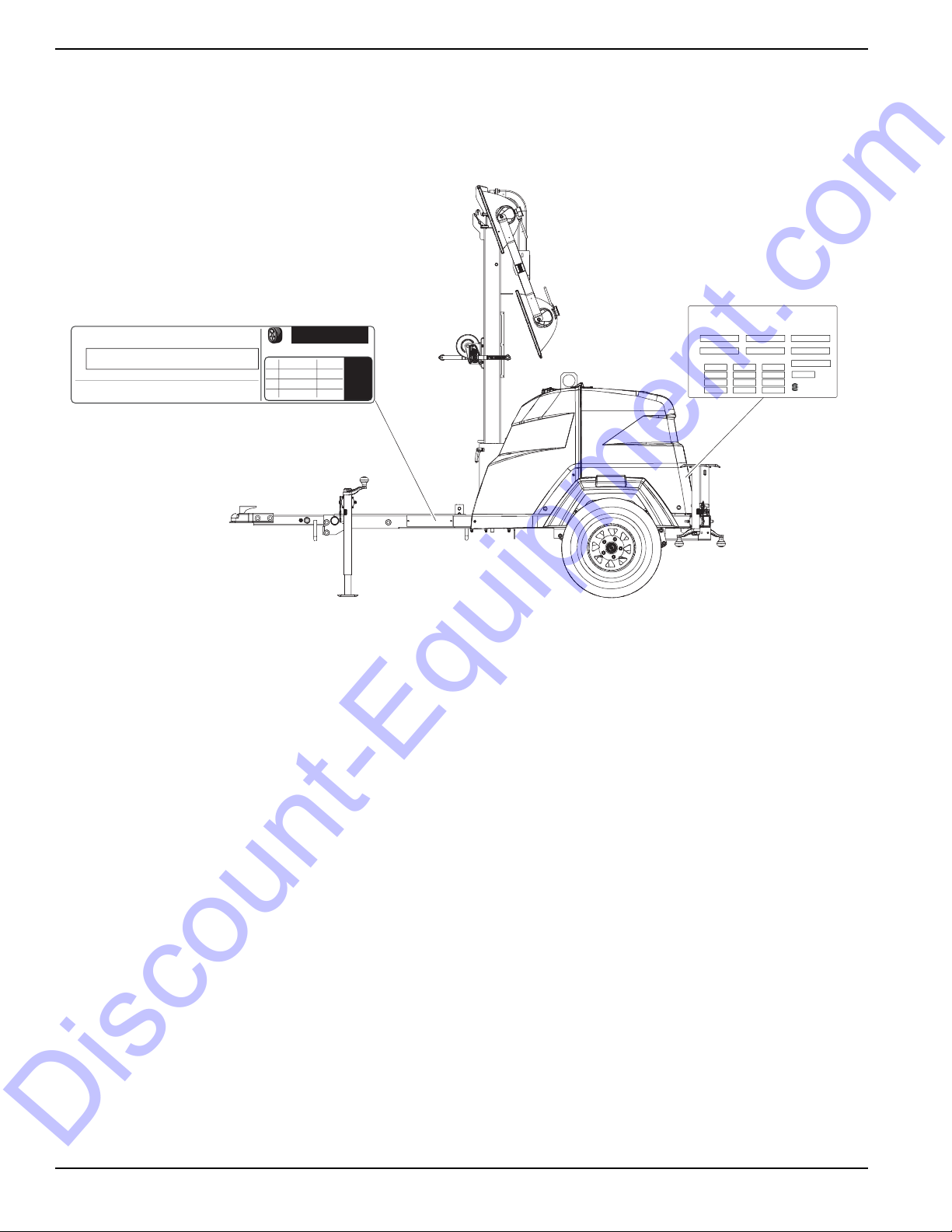
Unit Serial Number Locations
Refer to the illustration to locate the unit ID tag and Vehicle Identification Number (VIN) tag on the unit. Important
information, such as the unit serial number, model number, VIN and tire loading information are found on these tags.
Record the information from these tags so it is available if the tags are lost or damaged. When ordering parts or
requesting assistance, you may be asked to provide this information.
Figure 2-1. Serial Number Locations
12 Owner’s Manual for MLT6SC Light Tower
Page 17
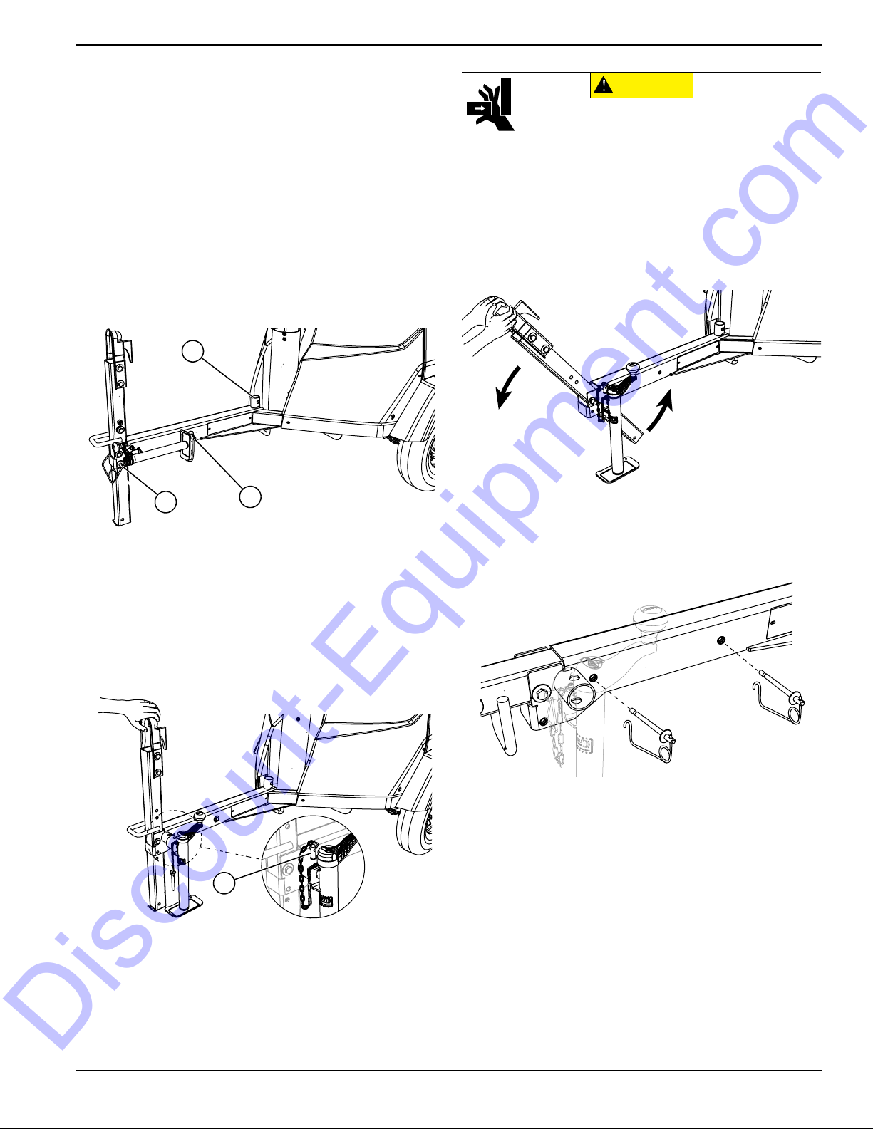
Trailer Tongue Storage and Tow
A
B
C
003517
D
CAUTION
(000313)
Pinching and crushing hazard. To avoid
possible injury, keep fingers away from pivot
point when folding or unfolding trailer tongue.
003519
Discount-Equipment.com
Positions
The trailer tongue is designed to fold upright for shipping
and storage.
IMPORTANT NOTE: Do not attempt to tow the unit with
trailer tongue in the storage position.
Place Trailer Tongue in Tow Position
1. Verify unit is on a level surface and wheels are
blocked.
NOTE: See Figure 2-2. Unit ships from factory with jack
in the storage location (A).
General Information
6. See Figure 2-4. Using both hands, slowly lower
trailer tongue into tow position.
NOTE: Varying levels of effort may be required
depending on terrain.
003591
Figure 2-2. Jack and Pin Locations
2. Remove clevis securing jack parallel to ground.
3. Remove jack from tongue weldment. Hold jack
vertically and extend until weldment on jack is
aligned with tongue weldment.
4. See Figure 2-3. Install jack and secure with clevis
(D).
Figure 2-4. Lower Trailer Tongue into Tow Position
7. See Figure 2-5. Install pins as shown to secure
trailer tongue in tow position.
003592
Figure 2-5. Install and Secure Pins
5. See Figure 2-2. Remove pins (B) and (C).
Figure 2-3. Jack Installed
Owner’s Manual for MLT6SC Light Tower 13
Page 18

General Information
003593
A
B
C
CAUTION
(000313)
Pinching and crushing hazard. To avoid
possible injury, keep fingers away from pivot
point when folding or unfolding trailer tongue.
003520
A
B
C
Discount-Equipment.com
Place Trailer Tongue in Storage Position
1. Verify unit is on a level surface and wheels are
blocked.
2. See Figure 2-6. Extend jack (A) enough to allow
minimum effort to pivot trailer tongue into storage
position.
Figure 2-6. Extend Jack and Remove Pins
3. Remove pins (B) and (C) from trailer tongue.
003591
Figure 2-8. Install Pins and Rotate Jack
6. Remove clevis and remove jack (A) from tongue
weldment.
7. Completely retract jack.
8. Rotate jack 90° counterclockwise, place jack on
tongue weldment, and install clevis to secure jack
parallel to ground.
4. See Figure 2-7. Pivot trailer tongue into storage
position.
NOTE: Varying levels of effort may be required
depending on terrain.
Figure 2-7. Pivot Trailer Tongue Into Storage Position
5. See Figure 2-8. Install pins (B) and (C) at locations
shown to secure trailer tongue in storage position.
14 Owner’s Manual for MLT6SC Light Tower
Page 19

Unit Dimensions
A
B
D
C
E
006451
Discount-Equipment.com
General Information
Figure 2-9. Unit Dimensions
ABCDE
MLT6SC 118 in. (3 m) 101 in. (2.6 m) 23 ft. (7 m) 57 in. (1.5 m) 120.5 in. (3.1 m)
Specifications are subject to change without notice.
######
Owner’s Manual for MLT6SC Light Tower 15
Page 20

General Information
######
006452
B
F
C
D
G
H
A
D
E
Discount-Equipment.com
Component Locations
Figure 2-10. Component Locations—Front and Left Side
A. Grounding studs:
Interior: On enclosure floor behind controller
Exterior: On bumper
B. Outriggers and jacks (2) F. Mast rotation knob
C. Fuel fill G. Winch
D. Tie-down location H. Lights (4)
16 Owner’s Manual for MLT6SC Light Tower
E. Tongue jack
Page 21

General Information
######
J
K
L
L
M
N
P
006453
Discount-Equipment.com
Figure 2-11. Component Locations—Rear and Right Side
J. Central lift point M. Tandem tow mount (optional—not shown)
K. Engine/radiator access hood N. Hood latch
L. Forklift pocket P. Key start controller
or Power Zone-DLA controller (optional—not shown)
Owner’s Manual for MLT6SC Light Tower 17
Page 22

General Information
STOP
15 SEC.
MAX.
12V
DC CIRCUIT
BREAKER
AC CIRCUIT
BREAKER
120V
I
O
I
O
I
O
I
O
MAIN
BREAKER
240V
I
O
AC CIRCUIT
BREAKERS
DC CIRCUIT
BREAKER
MAST LIGHT CIRCUIT BREAKERS
MAIN CIRCUIT
BREAKER
CONTROL
POWER
A
004385a
B
C
C
D
E
F
G
H
I
K
F
E
A
B
I
H
J
Controller with Power Zone (If Equipped) Controller without Power Zone
Discount-Equipment.com
Control Panel
Figure 2-4. Control Panel
Control Panel Features and Functions
(A) DC circuit breaker
Resets the DC electrical circuit that powers the control
panel and engine components.
(B) AC circuit breaker
Resets the AC electrical circuit that powers the control
panel.
(C) Mast light toggle switch/circuit breakers (4)
Power switches with internal breakers dedicated to
individual lights
(D) Mast switch (if equipped)
Raises and lowers the mast on units equipped with an
electric winch.
(E) 120V/20A GFCI outle t
Customer convenience outlet for use in connecting
auxiliary equipment such as fans, pumps, drills. Includes
a Ground Fault Circuit Interrupter (GFCI) test and reset
button.
(F) 240VAC/30A twist-lock outlet
Customer convenience outlet for use in connecting
auxiliary equipment such as fans, pumps, drills.
(G) Engine hour meter
Displays number of hours the engine has run.
(H) Main circuit breaker
240V/30A breaker which disconnects power from the
lights and control panel.
(I) Control power switch
Turns the engine ON and OFF.
(J) Power Zone controller
Monitors the unit and indicates operational status and
fault conditions.
(K) Mast light circuit breakers (4)
Power switches with internal breakers dedicated to
individual lights
18 Owner’s Manual for MLT6SC Light Tower
Page 23

General Information
Select
H
G
F
E
D
C
B
A
002353
Discount-Equipment.com
Power Zone–DLA (If Equipped)
The Power Zone–DLA is an AUTO start controller that
monitors the unit and indicates operational status and
fault conditions. The controller can be programmed to
automatically start or stop based on time schedule, fault
condition, or load demand.
The controller constantly monitors vital generator and
engine functions for a number of preprogrammed alarm
and fault conditions. When a fault condition occurs, the
engine will be shut down automatically and the LCD
window will show the fault that caused the shutdown. To
resume operation, the fault condition must be corrected.
This controller also records a history of unit performance,
which may be viewed at any time and will not be lost
when the controller is powered down.
Figure 2-5. Power Zone–DLA Layout
Controller Features and Functions
(A) The Liquid Crystal Display (LCD) Window
This window displays the various operating screens. By
viewing these screens, the operator can monitor both the
engine and generator status while the unit is running.
(B) Select LED
This LED illuminates when the unit is running in AUTO
mode.
(C) Start LED
This LED illuminates when the unit is running in MANUAL
mode.
(D) Start Button
This button starts the engine if there are no shutdown
errors and the engine is in “ready to start” status.
(E) Stop Button
This button shuts down the unit and puts the controller
into STOP mode, whether in MANUAL mode or AUTO
mode.
(F) Stop LED
This LED illuminates when the unit is in STOP mode and
flashes when an Electrical Trip and Shutdown Fault has
occurred.
(G) Select Button
This button confirms entries chosen in the various edit
menus and screens.
(H) Menu Navigation
These buttons (↑, ↓) are used to navigate through the
various operator screens. They are also used to raise
and lower the mast on units equipped with an electric
winch.
NOTE: To prevent damage to the generator and
connected equipment, remove all loads from the
generator by opening all circuit breakers (turn OFF [O])
before pressing the STOP button.
Owner’s Manual for MLT6SC Light Tower 19
Page 24

General Information
002354
002544
002990
002327
Discount-Equipment.com
Operator Screens
See Figure 2-6. The operator screens display the most
relevant and critical information an operator will need to
properly configure and use the unit. From these six
screens, the operator can access information necessary
to operate the unit under normal conditions.
Figure 2-6. Operator Screens Location
Home Screen
See Figure 2-7. The Home screen is the default screen
of the controller and displays after the controller is
powered up and the unit management software is
loaded. It displays the controller mode, total operating
hours, hours left until the next service interval, engine
operating status, and engine RPM. If the unit is in AUTO
mode, the Home screen may also display whether the
scheduler or “dusk to dawn” are enabled.
Battery Voltage Screen
See Figure 2-8. Displays the engine battery voltage. A
normal reading is 12-14V on 12 volt systems (with the
engine running).
Figure 2-8. Battery Voltage Screen
Lights Screen
See Figure 2-9. The Lights screen enables the operator
to turn the lights on and off. Refer to Light Operation for
more information.
Figure 2-7. Home Screen
20 Owner’s Manual for MLT6SC Light Tower
Figure 2-9. Lights Screen
Page 25

General Information
002980
002981
002328
002329
Discount-Equipment.com
Line Amperage Screen
See Figure 2-10. The Line Amperage screen displays
the AC output amperage produced by the generator in
Amps (A). The load balance for each line (L1 and L3) is
displayed in both numerical and graphical form. It is
important to maintain a balanced load distribution
between lines for optimum generator performance.
Figure 2-10. Line Amperage Screen
Generator Screen
See Figure 2-11. The Generator screen displays the
average line voltage, frequency (in Hertz), and power
factor for the generator while in operation.
Dusk to Dawn Screen
NOTE: This feature will only work in AUTO mode.
See Figure 2-12. The Dusk to Dawn screen enables or
disables the “dusk to dawn” function. This function uses a
photo sensor to detect the surrounding light level,
automatically starting the engine and turning the lights on
at dusk. The engine will run and the lights will remain
illuminated until dawn.
Figure 2-12. Dusk to Dawn Screen
Figure 2-11. Generator Screen
Scheduler Screen
NOTE: This feature will only work in AUTO mode.
See Figure 2-13. The Scheduler screen enables the
operator to program specific times for the lights to turn on
and off. Once programmed, the Scheduler will start the
engine and illuminate the lights until the designated
shutdown time.
Figure 2-13. Scheduler Screen
Owner’s Manual for MLT6SC Light Tower 21
Page 26

General Information
002329
002544
003780
Discount-Equipment.com
Maintenance Screens
See Figure 2-14. The information displayed on the
maintenance screens can be used to identify, diagnose
and troubleshoot unit shutdown conditions and poor unit
performance..
Figure 2-14. Maintenance Screens
Icon Description
Home screen
Alarms screen
Maintenance screen
Home Screen
See Figure 2-15. The Home ( ) screen is the default
screen of the controller and displays after the controller
has powered up. The controller automatically returns to
Home from any other screen after a period of inactivity.
Figure 2-15. Home Screen (MANUAL Mode Shown)
Alarms Screen
See Figure 2-16. The Alarms ( ) screen displays all the
alarms, warnings, and engine Diagnostic Trouble Code
(DTC) faults. When an alarm occurs, the controller
automatically switches to this screen and remains there
until the alarm is cleared. The Stop LED also flashes.
Event log screen
About screen
To enter the navigation menu, use the following
procedure:
1. Press both the ↑ and ↓ buttons simultaneously.
2. To select the required icon, press the ↑ button to
cycle right and the ↓ button to cycle left until the
desired operator screen section is reached.
3. Once the desired icon is at the top, press the
Select () button to enter that operator screen
section.
NOTE: Every time the operator screens are entered, the
home icon will be located at the top of the screen.
Figure 2-16. Alarms Screen
• Warnings are non-critical alarm conditions and do
not affect the operation of the generator system.
They serve to draw the operator’s attention to an
undesirable condition. By default, warning alarms
are self-resetting when the fault condition is
removed.
• Electrical trips stop the generator in a controlled
manner. On initiation of the electrical trip condition,
the controller de-energizes all the outputs,
including the lights, to remove the load from the
generator. Once this has occurred, the controller
starts the cooling timer and allows the engine to
cool off-load before shutting down the engine.
• Shutdown alarms stop the generator immediately.
On initiation of the shutdown condition, the
controller de-energizes all the outputs, including
the lights, to remove the load from the generator.
22 Owner’s Manual for MLT6SC Light Tower
Page 27

General Information
003781
003782
Discount-Equipment.com
Once this has occurred, the controller shuts the
generator set down immediately to prevent further
damage.
• DTC faults are displayed by the controller.
Table 2-1. Possible DTC Faults
Fault DTC Description
Check Engine
Fault
Low Oil Pressure Engine oil pressure has fallen below
Underspeed Engine speed has fallen below its
Overspeed Engine speed has risen above its
Low Fuel Level Engine’s fuel level has fallen below its
Battery Under/
Over Voltage
To view the active alarms, repeatedly press the ↑ and ↓
buttons until the LCD window displays the alarm.
Continue to press the ↑ and ↓ buttons to cycle through
the alarms.
To exit the alarm screen, press the ↑ and ↓ buttons
simultaneously to enter the navigation menu. Once
entered, cycle to the desired operator screen.
A fault not recognized by the controller
has been detected. Contact the engine
manufacturer for support.
its configured low oil pressure alarm
level.
configured underspeed alarm level.
configured overspeed alarm level.
configured low fuel level alarm.
Engine’s DC supply has fallen below
or risen above its configured alarm
level.
Maintenance Screen
See Figure 2-17. The Maintenance screen ( ) displays
the maintenance alarms configured into the controller.
The three alarms are for servicing the fuel filter, oil filter,
and air filter.
Figure 2-17. Maintenance Screen
Event Log Screen
See Figure 2-18. The controller’s event log ( ) displays
a list of the last 15 recorded electrical trips or shutdown
events and the engine hours at which they occurred.
Once the log is full, any subsequent electrical trip or
shutdown alarm overwrites the oldest entry in the log.
Therefore, the log always contains the most recent
shutdown alarms.
NOTE: The alarm condition must be corrected before a
reset will take place. If the alarm condition remains, it is
not possible to reset the unit. The exception to this is the
Low Oil Pressure alarm and similar ‘active from safety on’
alarms, as the oil pressure is low with the engine at rest.
To clear alarms that stop the generator, refer to
Resetting the Maintenance Alarms (If Equipped).
NOTE: The LCD backlight is on if the unit has sufficient
voltage while the unit is turned on, unless the unit is
cranking. In this case, the backlight is turned off.
If the controller is left in STOP mode for a period of
inactivity, the controller enters POWER SAVE mode. To
‘wake’ the controller, press the Stop (O) button.
Owner’s Manual for MLT6SC Light Tower 23
To view the event log:
1. Press both ↑ and ↓ buttons simultaneously to
2. Cycle to the event log section and press the Auto
3. Repeatedly press the ↑ or ↓ buttons until the LCD
Continuing to press down the ↑ or ↓ buttons will cycle
through past alarms. Eventually the most recent alarm
will display and the cycle begins again.
To exit the event log, press the ↑ and ↓ buttons
simultaneously to enter the navigation menu. Once
entered, cycle to the desired operator screen.
Figure 2-18. Event Log Screen
display the navigation menu.
button to enter.
window displays the desired event.
Page 28

General Information
003783
Discount-Equipment.com
About Screen
See Figure 2-19. The About ( ) screen contains
information about the controller such as the controller’s
date and time, the product and USB identification
number, and the application and engine version.
Figure 2-19. About Screen
24 Owner’s Manual for MLT6SC Light Tower
Page 29

Section 3: Operation
A
E
G
B
F
D
C
006454
(000260a)
High Voltage. Verify area above unit is clear
of overhead wires and obstructions. Contact
with high-voltage power lines will result in
death or serious injury.
DANGER
WARNING
(000297)
> 60 mph> 60 mph
Do not set up the unit if high winds
are expected. High winds can cause the
unit to tip or fall, causing severe injury
or machine damage.
Discount-Equipment.com
Light Tower Setup
Operation
DETAIL B
DETAIL C
DETAIL D
1”
DETAIL E
Figure 3-1. Set Up Outriggers and Jacks
2. See Figure 3-1. Place the unit on firm ground that
is relatively flat (less than 5° slope), and then block
the wheels to keep it from moving. This will make it
easier to level the unit.
3. Pull the locking pin (A) on the tongue jack (E) and
rotate the jack 90°. Reinstall the locking pin. Rotate
the jack handle clockwise to raise the trailer tongue
off the towing vehicle.
4. A grounding stud (B) is located on the rear frame of
5. See Details C—D. Pull the locking pins (C) on the
1. For maximum light coverage, position the unit at
NOTE: The mast extends up to 23 ft (7m).
Owner’s Manual for MLT6SC Light Tower 25
ground level or in a spot higher than the area being
illuminated by the lamps.
the trailer near the left side outrigger. For
grounding requirements, follow local, state, and
National Electrical Code (NEC) regulations.
outriggers (D) and pull each outrigger out until the
spring loaded locking pin snaps back into place.
Pull the locking pin on each outrigger jack (F) and
rotate each jack 180° so the jack pad is facing
down. Reinstall the locking pin.
Page 30

Operation
(000100a)
WARNING
Consult Manual. Read and understand manual
completely before using product. Failure to
completely understand manual and product
could result in death or serious injury.
DANGER
Electrocution. DO NOT use the unit if
electrical cord is cut or worn through. Doing
so will result in death or serious injury.
(000263a)
WARNING
Tipping hazard. Extend the outriggers and level the unit
before raising the mast. Keep the outriggers extended
while the mast is up. Failure to do so could cause the unit
to tip and fall and could result in death or serious injury.
(000266)
DETAIL D
STOP
A
D
B
C
002532
Discount-Equipment.com
6. See Detail E. Rotate each jack handle clockwise to
start leveling the trailer. Adjust all three jacks by
rotating their handles clockwise until they are firmly
in contact with the ground. Continue until the
wheels are approximately one inch (2.5 cm) off the
ground (G).
7. Before raising the mast, it may be necessary to
adjust the lamps. The lamps may be adjusted up,
down, left or right by simply aiming them in the
desired direction.
Prestart Checklist
Before starting the unit, all items in the prestart checklist
must be completed. This checklist applies to both manual
and remote starting of the unit.
Verify all maintenance procedures are up to date. For
more information, refer to General Maintenance and
Basic Maintenance Schedule.
The unit must be level.
The unit must be dry. Look for water inside or near
the unit; dry if needed.
For grounding requirements, follow the local, state,
or National Electrical Code (NEC) regulations.
Verify the Control Power switch is in the OFF (O)
position.
Verify all circuit breakers are in the OFF (O) position.
Raising the Mast—Manual Winch
1. Set up and level the unit. See Light Tower Setup.
Inspect all electrical cords; repair or replace any that
are cut, worn, or bare.
Verify all winch cables are in good condition and
centered on each pulley. Do not use if cables are
kinked or beginning to unravel.
Check oil, coolant, and fuel levels. For more
information, refer to General Maintenance.
Verify battery connections are secure.
Turn the battery disconnect switch on, if equipped.
Check the engine fan belt tension and condition.
Check the engine fan belt guard.
Check the engine exhaust system for loose or rusted
components.
Verify all covers are in place and secure.
26 Owner’s Manual for MLT6SC Light Tower
Figure 3-2. Pulley Locations - Manual Winch
Page 31

Operation
WARNING
Tipping hazard. Do not extend the mast beyond the
colored mark on the second mast section. The unit
can become unstable and tip or fall, causing injury.
(000262)
WARNING
Personal Injury. Stop immediately if the mast hangs
up or the winch cable develops slack. Excess slack
could cause the mast to collapse, resulting in personal
injury or equipment damage.
(000265)
(000279)
Personal injury or equipment damage. Do not raise
or lower the mast while the unit is operating.
Doing so can break the lenses and cause the
lamps to shatter.
WARNING
DANGER
Electrocution. DO NOT use the unit if
electrical cord is cut or worn through. Doing
so will result in death or serious injury.
(000263a)
WARNING
Tipping hazard. Extend the outriggers and level the unit
before raising the mast. Keep the outriggers extended
while the mast is up. Failure to do so could cause the unit
to tip and fall and could result in death or serious injury.
(000266)
DETAIL C
STOP
DETAIL B
A
C
B
002533
D
Discount-Equipment.com
2. See Figure 3-2. Check the mast cables for
excessive wear or damage. Verify the cables are
properly centered in each pulley (A). Check the
electrical cord for damage.
3. Rotate the mast by loosening the mast rotation
knob (C) at the bottom of the mast. Turn the mast
until the lights face in the desired direction, and
then tighten the mast rotation knob to secure the
mast in position.
Using both hands, rotate the winch (B) to slowly
4.
extend the mast, making sure that the coiled
electrical cord is extending at the top sections of the
mast. STOP extending the mast when the colored
mark (D) on the second mast section is visible as
seen in Detail D.
Raising the Mast—Electric Winch
(If Equipped)
1. Set up and level the unit. See Light Tower Setup.
IMPORTANT NOTE: Contact a Generac Mobile
Products Authorized Service Dealer immediately if
the mast hangs up or the winch cable develops
slack.
Owner’s Manual for MLT6SC Light Tower 27
Figure 3-3. Switch & Pulley Locations - Electric Winch
Page 32

Operation
WARNING
Tipping hazard. Do not extend the mast beyond the
colored mark on the second mast section. The unit
can become unstable and tip or fall, causing injury.
(000262)
WARNING
Personal Injury. Stop immediately if the mast hangs
up or the winch cable develops slack. Excess slack
could cause the mast to collapse, resulting in personal
injury or equipment damage.
(000265)
(000279)
Personal injury or equipment damage. Do not raise
or lower the mast while the unit is operating.
Doing so can break the lenses and cause the
lamps to shatter.
WARNING
002752
Discount-Equipment.com
2. See Figure 3-3. Check the mast cables for
excessive wear or damage. Verify the cables are
properly centered in each pulley (A). Check the
electrical cord for damage.
3. Rotate the mast by loosening the mast rotation
knob at the bottom of the mast (D). Turn the mast
until the lights face in the desired direction and
then tighten the mast rotation knob to secure the
mast in position.
4. Start unit according to Manually Starting the Unit.
Press and hold the winch control switch (Detail B)
5.
upward to telescope the mast to the desired height.
While doing so, verify that the coiled electrical cord is
extending at the top sections of the mast. STOP
extending the mast when the colored mark (C) on the
second mast section is visible as seen in Detail C.
IMP O R TAN T N O T E : A limit switch on the main mast
section will disconnect power to the upper electric
winch to prevent overextending the mast.
1. See Figure 3-4. Verify the main circuit breaker and
individual circuit breakers for each of the lights are
OFF (O).
Figure 3-4. Circuit Breakers in OFF (O) Position
2. See Figure 3-5. Turn the key on the Engine Start
switch to the right GLOW PLUG position and hold
the key in place for five seconds.
IMPORTANT NOTE: Contact a Generac Mobile
Products Authorized Service Dealer immediately if
the mast hangs up or the winch cable develops
slack.
Starting the Unit
NOTE: If the engine was run out of fuel or the fuel tank
was drained, it may be necessary to bleed the fuel lines.
Refer to the engine operator’s manual supplied with the
unit.
28 Owner’s Manual for MLT6SC Light Tower
Figure 3-5. Activate Glow Plug
3. See Figure 3-6. Turn the key to the right START
position and hold it until the engine cranks and
starts running.
Figure 3-6. Crank Engine
Page 33

Operation
CAUTION
(000230)
Equipment Damage. Do not continuously crank
engine for more than ten seconds. Doing so will lead
to overdischarge of batteries and starter seizure.
002354
(000277)
WARNING
Burn hazard. Never operate lights with a
damaged or missing lens cover. Lamps are
hot and pressurized while in use. Unprotected
lamps can shatter, causing severe injury.
Discount-Equipment.com
4. See Figure 3-7. Release the key, it will move to the
RUN position.
Figure 3-7. Release Key
Preparing for Start-Up (with
Power Zone Controller, If
Equipped)
NOTE:
drained, it may be necessary to bleed the fuel lines before
starting. Refer to the engine manual supplied with the unit.
If the engine was run out of fuel or the fuel tank was
Manually Starting the Unit
STOP mode is the default start-up setting for all units
equipped with the Power Zone–DLA. Use the following
procedure to start the generator in MANUAL mode.
1. Verify the 240VAC outlet breaker is switched OFF
(O).
2. Switch the main circuit breaker ON (I).
3. Verify that the Load Sense switch is OFF.
4. When the controller powers up, the Home screen
displays on the LCD screen and the Stop LED
illuminates to indicate that the controller is in STOP
mode. Press the Start button to initiate the startup
procedure. Assuming there are no existing engine
faults, the engine will start and the Start LED will
illuminate.
NOTE: The engine can be started from any screen. It
may take a few seconds for the engine to run smoothly
and reach its governed operating speed.
5. If the engine does not start after the first cranking
attempt, the engine will pause for 15 seconds to
allow the starter to cool. The controller backlight
will go out. The engine will make two more
attempts to start for a total of three crank cycles.
6. If the engine does not start and run within three
starting cycles, the LCD screen will display the
“Fail to Start” alarm. The starting sequence can be
repeated after the starter cools for at least two
minutes. Pressing the Stop (O) button will clear the
alarm and reset the controller.
Select AUTO or MANUAL Mode
See Figure 3-8. Using the arrows on the Power Zone–
DLA, select either AUTO or MANUAL on the Home
screen.
• AUTO mode is required for programming
automatic start and stop times (see Scheduler
Screen), or enabling the “dusk to dawn” sensor
(see Dusk to Dawn Sensor).
• MANUAL mode is used for on-demand control of
the lights and convenience outlets.
Figure 3-8. Select AUTO or MANUAL Mode
Owner’s Manual for MLT6SC Light Tower 29
Light Operation
1. Verify the unit is ON and running smoothly.
2. See Figure 3-9. Switch the main circuit breaker (A)
ON (I).
3. Switch the individual circuit breakers for the lights
(B) ON (I), one at a time.
4. The ballast indicator lights will turn on and continue
to get brighter as the lights warm up, and then
remain on. This confirms power is coming from the
ballasts to the lights.
Page 34

Operation
003991
A
B
(000278)
WARNING
Burn hazard. Lamps become extremely hot
while in use. Allow 10–15 minutes for cooling
before handling or lowering mast. Touching a
hot lens or fixture can cause severe burns.
(000278)
WARNING
Burn hazard. Lamps become extremely hot
while in use. Allow 10–15 minutes for cooling
before handling or lowering mast. Touching a
hot lens or fixture can cause severe burns.
Discount-Equipment.com
Figure 3-9. Light Switches and Breaker
NOTE: If an indicator light does not turn on, see
Troubleshooting or contact a Generac Mobile Products
Authorized Service Dealer.
NOTE: The lights require a warm up period of 5-15
minutes before they reach full output. If the lights are shut
down, they require a cool down period of approximately
ten minutes before they can be switched on again.
To turn the light(s) ON, press the Select () button. To
turn the light(s) OFF, press the Select () button.
NOTE: The light tower uses four 1000W or 1050W
bulbs. When checking or replacing the bulbs, wipe them
with a clean cloth to avoid leaving any grease, oil residue
or fingerprints on the glass. Any residue can create a hot
spot on the bulb, causing premature bulb failure.
Figure 3-10. Lights Screen
Engine Derating
All units are subject to derating for altitude and
Light Operation (With Power
Zone Controller, If Equipped)
See Figure 3-10. The lights are turned on and off using
the Power Zone–DLA. To view the light screen, press the
↑ button three times from the Home screen.
NOTE: The lights can only be turned ON and OFF while
the unit is running in MANUAL mode. They operate
automatically in AUTO mode.
1. Once the engine is up to temperature and running
smoothly, switch the main circuit breaker ON (I).
30 Owner’s Manual for MLT6SC Light Tower
temperature. Derating reduces the available power for
operating tools and accessories connected to the outlets.
For every increase in 1000 ft (305 m) of elevation, engine
performance for this unit typically drops between 2% and
4%. Also, engine performance decreases about 1% for
every 10ºF (5.6ºC) increase in ambient air temperature
over 72ºF (22ºC).
Wet Stacking
The unit is powered by a diesel engine. Diesel engines
are subject to “wet stacking” if lightly loaded. Wet
stacking occurs when an engine is run at less than 30%
of its full load capacity, causing unburned fuel to
accumulate in the exhaust system. Wet stacking can be
detected by continuous black exhaust when the unit is
under a constant load. It can also cause fouling of
injectors and buildup on engine valves. Diesel engines
operate properly when applied loads are between 30%
and 100% capacity. Appropriate generator sizing is
Page 35

Operation
A
B
002535
Discount-Equipment.com
determined by the anticipated load. If the unit is in a wet
stack condition, load the unit heavily for five hours or until
the exhaust is clear.
Dusk to Dawn Sensor
This unit is equipped with a “dusk to dawn” photo sensor
to detect the surrounding light level, automatically
starting the engine and turning the lights on at dusk. The
engine will run and the lights will remain illuminated until
dawn.
To prepare the sensor for use, perform the following
procedure at the time of day you want the lights to turn
on:
1. Verify the Power Zone–DLA is set up and the unit
is ON.
2. Slide the light shield bracket up, decreasing the
sensor’s exposure to light, until the lights turn ON.
3. Tighten screws on shield.
Customer Convenience Outlets
See Figure 3-11. The unit is equipped with convenience
receptacles for powering accessories or tools from the
generator. Power is supplied to the receptacles any time
the engine is running and the main circuit breaker is
switched to the ON (I) position. Each outlet has an
individual circuit breaker, located on the control box.
Refer to Control Panel.
With all of the lights OFF, the full generator output may be
used with the 240V twist-lock receptacle.
Shutting Down the Unit
Check with personnel using power supplied by the unit
and let them know the power is going to be turned off.
Make sure the power shutdown will not create any
hazards by accidentally turning off equipment that needs
to remain running (pumps, compressors, lights, etc.).
1. Remove all loads from the outlets.
2. Switch the individual circuit breakers for each light
OFF (O).
3. Switch the main circuit breaker OFF (O).
4. Move the control power switch to STOP.
Shutting Down the Unit (with
Power Zone Controller, If
Equipped)
Check with personnel using power supplied by the unit
and let them know the power is going to be turned off.
Verify the power shutdown will not create any hazards by
accidentally turning off equipment that needs to remain
running (pumps, compressors, lights, etc.).
1. Remove all loads from the outlets.
2. Turn the lights OFF using the controller.
3. Switch the outlet breaker OFF (O).
4. Press the Stop (O) button.
5. After the unit shuts down, switch the main circuit
breaker OFF (O).
Figure 3-11. Convenience Outlets
The circuit breakers are labeled with the corresponding
voltage for the receptacle they protect. The standard
receptacle panel is equipped with the following
receptacles:
• One 240V/30A Twist-lock (A)
• One 120V/20A GFCI (B)
NOTE:
receptacle when the lights are on. This will overload the
generator and cause the main circuit breaker to trip.
Should the breaker trip, switch off the lights, remove some
of the loads connected to the receptacles and wait ten
minutes for the bulbs to cool before turning them back on.
Do not draw more than 1000W from each
NOTE: Disconnect the battery if the unit is to be stored
for an extended period. Refer to the engine operator’s
manual for additional extended storage procedures.
Automatic Shutdown
This unit is equipped with a low oil pressure and high
coolant temperature automatic shutdown system. This
system will automatically shut off the fuel supply to stop
the engine if oil pressure drops too low or the engine
exceeds normal operating temperature. Return the main
circuit breaker to the STOP position to reset the unit after
the cause of shutdown has been determined.
Lower Radiator Hose Heater (If
Equipped)
The lower radiator hose heater is designed to prevent
engine coolant from freezing in extreme cold weather
conditions. While the heater is designed to be operated
overnight if necessary, two to five hours of heating just
prior to starting is usually sufficient for proper engine
starting.
Owner’s Manual for MLT6SC Light Tower 31
Page 36

Operation
A
006440
(000278)
WARNING
Burn hazard. Lamps become extremely hot
while in use. Allow 10–15 minutes for cooling
before handling or lowering mast. Touching a
hot lens or fixture can cause severe burns.
WARNING
Personal Injury. Stop immediately if the mast hangs
up or the winch cable develops slack. Excess slack
could cause the mast to collapse, resulting in personal
injury or equipment damage.
(000265)
003990
Discount-Equipment.com
NOTE: Use the lower radiator hose heater only in its
designated location. Improper use can damage the
engine.
Perform the following steps when operating a unit
equipped with a lower radiator hose heater.
1. Verify that the unit is level so as to maintain proper
orientation of the heater while it is in operation.
2. Verify that the cooling system is full of the proper
mixture of water and engine coolant before each
heater use.
3. Use only an undamaged, outdoor rated, threeprong grounded 120VAC extension cord with a
minimum amperage rating of 10A. Connect the
cord to a properly grounded 120VAC, GFCI outlet.
4. Before starting the engine, unplug the extension
cord from the power first, then unplug the heater
cord set from the extension cord.
Tandem Tow (If Equipped)
The tandem tow hitch option (A) allows the operator to
tow a second MLT6 Light Tower in series behind the unit
equipped with the hitch.
Lowering the Mast—Manual
Winch
1. Shut down the lights and engine. See Shutting
Down the Unit.
2. Lower the mast.
3. Use the winch handles to collapse the mast to its
lowest position. Ensure the electrical cord does not
get caught in, or pinched by, the mast while it is
being lowered.
IMPORTANT NOTE: Contact a Generac Mobile
Products Authorized Service Dealer immediately if
the mast hangs up or the winch cable develops
slack.
Figure 3-12. Tandem Tow
Telemetry (If Equipped)
The digital telemetry option enables the operator to
remotely monitor the unit fuel level. A transmitter inside
the engine compartment sends real time equipment
status information to the user via cellular or satellite
connection.
Spark Arrester (If Equipped)
A spark arrester, installed on the MLT exhaust, may be
required by code in certain municipalities. Check with the
local authority having jurisdiction to determine whether or
not a spark arrester must be installed on the unit before
operation.
4. See Figure 3-13. I
rotate the mast so the lights face the rear of the unit
Figure 3-13. Stowed (Travel) Position
To rotate the mast:
a. Loosen the mast rotation knob.
b. Rotate the mast until the white arrows are
aligned and the metal stop tabs are touching.
c. Tighten the mast rotation knob.
f the unit is going to be moved,
.
32 Owner’s Manual for MLT6SC Light Tower
Page 37

Operation
(000278)
WARNING
Burn hazard. Lamps become extremely hot
while in use. Allow 10–15 minutes for cooling
before handling or lowering mast. Touching a
hot lens or fixture can cause severe burns.
WARNING
Personal Injury. Stop immediately if the mast hangs
up or the winch cable develops slack. Excess slack
could cause the mast to collapse, resulting in personal
injury or equipment damage.
(000265)
002832
Discount-Equipment.com
Lowering the Mast—Electric Winch
(If Equipped)
1. Press and hold the upper winch control switch
downward to collapse the mast to its lowest
position. Ensure the electrical cord does not get
caught in, or pinched by, the mast while it is being
lowered.
2. Shut down the lights and engine. See Shutting
Down the Unit.
If the unit is going to be moved, rotate the mast so
3.
the lights face the rear of the unit. To rotate the mast:
a. Loosen the mast rotation knob.
b. Rotate the mast until the white arrows are
aligned and the metal stop tabs are touching.
c. Tighten the mast rotation knob.
NOTE: Some electric winch models are equipped with
an anti-backlash safety limit switch. This switch
disconnects power to the winch after the mast is
completely lowered. This prevents the cable from
continuing to unwind and becoming entangled around the
winch drum.
IMPORTANT NOTE: Contact an Generac Mobile
Products Authorized Service Dealer immediately if
the mast hangs up or the winch cable develops
slack.
NOTE: If the generator is not operational, and the
batteries do not have enough power to lower the mast, it
may be necessary to lower the mast manually. Always
attempt to recharge the batteries and lower the mast
electrically before proceeding.
Manually Lowering the Mast
IMPORTANT NOTE: Do not use this procedure
unless it is absolutely necessary. Frequent use of
this procedure could damage the motor shaft.
Owner’s Manual for MLT6SC Light Tower 33
1. See Figure 3-14. Remove the motor cover (A).
Figure 3-14. Manually Lowering the Mast
2. Attach a drill chuck firmly to the exposed motor
shaft (B).
3. Using the drill, slowly rotate the motor shaft
counterclockwise to lower mast.
4. Detach the drill chuck and install the motor cover
after the mast is completely lowered.
Towing the Unit
Once the engine is shut down and the mast and lights are
properly stowed, follow these steps to prepare the unit for
towing.
1. Raise the outrigger jacks completely and release
the locking pins to rotate them up into the travel
position. Make sure the locking pins snap into
place. Release the outrigger locking pins and slide
the outriggers into the trailer frame until the locking
pins snap into place.
2. Use the tongue jack to raise or lower the trailer
onto the hitch of the towing vehicle. Lock the hitch
coupling and attach the safety chains or cables to
the vehicle. Remove the tongue jack locking pin
and rotate the jack into the travel position. Replace
the locking pin.
3. To ensure proper operation of the jacks, lubricate
the grease fittings located on the leveling jacks.
Refer to Jack Maintenance. For maintenance
interval information, refer to Basic Maintenance
Schedule.
4. Connect any trailer wiring to the tow vehicle. Check
for proper operation of the directional and brake
lights.
5. Verify the enclosure is properly latched.
6. Check for proper inflation of the trailer tires. For
maximum tire pressures, refer to Specifications.
7. See Figure 3-15. Check the wheel lugs. Tighten or
replace any lugs that are loose or missing. If a tire
has been removed for axle service or replaced,
tighten the lugs, in the order shown, to the
following specifications:
Page 38

Operation
5
2
3
4
1
003754
A
B
006456
C
002537
Discount-Equipment.com
Figure 3-15. Tightening Wheel Lugs
a. Start all lug nuts by hand.
b. First pass: tighten to 20-25 ft-lbs (27-33 Nm).
c. Second pass: tighten to 50-60 ft-lbs (67-81 Nm).
d. Third pass: tighten to 90-120 ft-lbs (122-162
Nm).
NOTE: After the first road use, re-torque the lug nuts in
sequence.
8. Maximum recommended speed for highway towing
is 45 mph (72 km/h). Recommended off-road
towing speed is not to exceed 10 mph (16 km/h) or
less, depending on the terrain.
Lifting the Unit
Follow these steps to prepare the unit for lifting:
1. Verify the equipment being used to lift the unit is in
good condition and has sufficient capacity. For
approximate weights, refer to Specifications.
2. Close and lock all hoods and doors.
3. See Figure 3-16. Stow the mast and lights in the
travel position as shown.
4. Always remain aware of people and objects around
the unit while preparing, maneuvering, and lifting
the unit.
Figure 3-16. Lifting Point
Use the forklift pockets (B) with care. Lift directly from the
rear. Avoid approaching the unit at an angle, as this can
permanently damage the forklift pockets, tires, or cabinet.
Verify any obstructions are clear of the forklift tines before
lifting.
Tying the Unit Down
When securing the unit for transportation, verify the
equipment being used to fasten the unit is in good
condition and has sufficient strength to hold the unit in
place during transport.
See Figure 3-17. Use the tie-down points (C) as shown.
• When lifting the unit, attach any slings, chains or
hooks directly to the central lift point (A). The
central lift point is located on top of the enclosure,
connected to a lift structure inside the unit.
34 Owner’s Manual for MLT6SC Light Tower
Figure 3-17. Tie-Down Points
Page 39

Section 4: Maintenance
CAUTION
(000306)
Equipment Damage. Failure to perform a daily
inspection could result in damage to the unit.
Discount-Equipment.com
Maintenance
Emissions Information
For warranty information, please refer to the diesel
engine manual supplied with this unit.
Daily Walk-Around Inspection
Perform a walk-around inspection of the unit every day
before starting the unit. Look for conditions that could
hinder performance or safety, such as (but not limited to):
• Oil, coolant and fuel leakage
• Blocked vents
• Loose or missing hardware
• Loose or broken electrical connections.
Inspect the fan belt for cracks, fraying, or stretching. Verify
the belt is properly seated in the pulley grooves. Replace
the belt according to the manufacturer’s recommendations.
General Maintenance
Poorly maintained equipment can become a safety
hazard. In order for the equipment to operate safely and
properly over a long period of time, periodic maintenance
and occasional repairs are necessary. DO NOT perform
routine service (oil and filter changes, cleaning, etc.)
unless all electrical components are shut off.
Regular maintenance will improve performance and
extend engine/equipment life. Generac Mobile Products
LLC recommends that all maintenance work be
performed by a Generac Mobile Products Authorized
Service Dealer. Regular maintenance, replacement or
repair of the emissions control devices and systems may
be performed by any repair shop or person of the owner’s
choosing. However, to obtain emissions control warranty
service free of charge, the work must be performed by a
Generac Mobile Products Authorized Service Dealer or
authorized Mitsubishi engine dealer depending on the
repair. See the emissions warranty.
Preparing for Service
Before servicing the unit, always follow the instructions
listed below.
1. If unit is equipped with the Power Zone controller,
verify the main circuit breaker is OFF. Otherwise,
verify the key switch is in the OFF position.
2. Verify the circuit breakers are switched OFF (O).
Owner’s Manual for MLT6SC Light Tower 35
3. Disconnect the negative (–) terminal on the battery.
4. Attach a “Do Not Start” sign to the control panel.
This will notify everyone that the unit is being
serviced and will reduce the chance of someone
inadvertently trying to start the unit.
Cleaning the Unit
Always clean the Light Tower after each use to remove
dust, grease, mud, or spilled fuel or oil. Use soft, clean
rags to wipe the cabinet exterior and control panel. Lowpressure compressed air (less than 40 PSI [276 kPa])
can also be used to remove dust and debris from the
cabinet interior.
This unit contains sensitive electronic components that
can be damaged by high pressure and heat. Therefore:
• Do not wash the unit with a high pressure hose or
power washer.
• Do not wash the engine block or fuel tank with a
power washer or steam cleaner. Water may enter
the cabinet and collect in the generator windings or
other electrical parts, causing damage.
Inspecting the Unit
•
If the unit is stored outside, check for water inside
the cabinet and generator before each use. If wet,
dry the unit thoroughly before starting.
• Inspect condition of electrical cords. DO NOT use
the unit if insulation is cut or worn through.
• Verify winch cables are in good condition and
centered on each pulley. DO NOT use a cable that
is kinked or starting to unravel.
• Verify the safety pins for the mast lock rod and
mast lock bar are present and secured with a
chain. Check that the spring located in the mast
lock bar is not broken or missing. Check the
operation of the mast lock bar.
• Verify the wheel lugs are present and properly
tightened. Refer to Towing Safety.
• Check the coolant level daily by inspecting the
level in coolant overflow jug located near the
radiator. Refer to the engine operator’s manual for
coolant recommendations and proper mixture.
Normal operating level is between the ‘full’ and
‘add’ markings on the overflow jug.
•
AFTER ENGINE IS STOPPED AND COMPLETELY
, coolant may be added directly to the coolant
COOL
overflow jug.
•
Check the oil level daily. Refer to the engine
operator’s manual for the appropriate oil specification.
Page 40

Maintenance
Discount-Equipment.com
Verify the oil is correct for special operating conditions
such as a change in season or climate.
• DO NOT start the unit if the engine oil level is
below the ADD mark on the dipstick.
• Normal operating level is in the cross-hatch
pattern between the full and add markings on
the dipstick.
dd oil only if the oil level is below the add mark
•A
on the bottom of the cross-hatch pattern on the
dipstick.
• Check the fuel level.
• If the unit is connected to a remote start or transfer
switch, make sure the remote switch is also off and
tagged.
NOTE: If the engine was run out of fuel or the fuel tank
was drained, it may be necessary to bleed the fuel lines.
Refer to the engine operator’s manual supplied with the
unit.
DO NOT OVERFILL
the crankcase.
Basic Maintenance Schedule
Refer to the original equipment manufacturer’s operating
manual for a complete list of maintenance requirements.
Failure to comply with the procedures as described in the
engine operator’s manual will nullify the warranty,
decrease performance and cause equipment damage or
premature equipment failure. Maintenance records may
be required to complete a warranty request.
Use the schedule in the following table as a guide for
regular maintenance intervals. For additional or
replacement copies of the engine operator’s manual,
contact a Generac Mobile Products Authorized Service
Dealer.
36 Owner’s Manual for MLT6SC Light Tower
Page 41

Table 4-1. Basic Maintenance Guide
Discount-Equipment.com
Maintenance
Item Daily
Check Oil Level
Check Coolant Level
Check Fuel Level
Check Tire Pressure
Inspect Wheel Bearings
Check Belt for Wear and Looseness
Check All Electrical Connections
Inspect Radiator Fins For Debris; Clean As Required
Inspect Light Tower Winch For Proper Operation
Check Fuel and Coolant Clamps for Tightness
Drain Water Separator
Sample Coolant
Inspect and Adjust Fan Belt
Sample Engine Oil
Clean / Replace Air Filter Element
Replace Fuel System Secondary Filter
Change Engine Oil and Filter
Check Engine Sensors (Oil Pressure and Coolant Temperature
Lubricate Leveling Jacks
Inspect Hoses and Clamps
Clean Radiator
Replace Alternator and Fan Belts
Adjust Valve Clearance
Inspect Engine Mounts
Replace Engine Breather
Inspect Alternator
Inspect Starter
Every
50
Hours
*
Every
250
Hours
Every
500
Hours
Every
1000
Hours
Every
2000
Hours
* Inspect after first 50 hours
Owner’s Manual for MLT6SC Light Tower 37
Page 42

Maintenance
003784
Discount-Equipment.com
Resetting the Maintenance
Alarms (If Equipped)
The Power Zone controller will display a warning
message when the unit is due for maintenance or
service. The maintenance or service interval is set at 750
hours of engine running time. Once the unit has been
serviced, the appropriate maintenance alarm reminder
needs to be reset. The following procedure demonstrates
how to reset the maintenance alarms:
1. With the unit shut down, move the Control Power
switch to the ON (I) position. After initialization, the
controller will toggle automatically to the Home
screen.
2. Press ↑ and ↓ simultaneously to enter the
navigation menu.
3. See Press ↑ or ↓ to move to the top of the
screen. Press to enter the Maintenance screen.
4. Press ↑ or ↓ to highlight the desired alarm that
needs to be reset. Press to start reset.
5. Enter the pin 4444. To do this, press and then ↑
or ↓ to adjust the first number of the maintenance
pin. Press to continue to the next number.
2. Verify the cable and cable attachments are not
damaged. Contact Generac Mobile Products to
order a replacement cable if necessary.
3. Referring to the “Lift / Let Down” decal on the
winch, turn handle according to the specified
direction to lift. The ratchet MUST make a loud
clicking sound while winding the cable.
Lowering the Lights:
Referring to the “Lift / Let Down” decal on the winch, turn
handle according to the specified direction to lower. No
clicking will be heard because the brake system is
activated.
Maintenance
The following procedures should be performed at least
annually:
1. The gears and bushings of the winch must be kept
lubricated. Apply a thin film of grease to the gear
teeth, and oil the bushings as needed.
2. The ratchet pawl pivot point must be kept
lubricated with a thin oil.
NOTE: Do not get oil or grease on the brake mechanism.
Figure 4-1. Entering Maintenance Pin
Manual Winch: Use, Operation,
and Maintenance
Prior to Use
•
Inspect rope or cable and replace if damaged.
• Check mounting hardware for proper tightness and
re-torque if necessary.
• Gears, ratchet pivot point and shaft bushings must
be kept lubricated with a thin film of oil or grease.
Operation
Raising the Lights:
1. The cable must be securely fastened to the winch
drum.
Electric Winch: Use, Operation,
and Maintenance
• Keep the winch free of dirt, oil, grease, water and
other substances.
• Check all mounting bolts and make sure they are
tightened to the recommended torque values.
Replace any damaged fasteners.
• Periodically check all connections to be sure they
are tight and free of corrosion.
• Check the cable for visible damage every time the
winch is operated. Examples of damage are: cuts,
knots, crushed or frayed portions, and broken
strands. Replace cable immediately if damaged.
Failure to replace a damaged cable could result in
breakage.
• Regularly check the brake for slippage or drift. This
is detected visually when winch is under load. If
winch drum continues to turn after controls are
released, the brake may need to be replaced.
• Periodically clean and grease the brake assembly.
This will ensure proper performance and extend
the life of the winch. If winch seems to labor or get
excessively hot during the lowering of loads, the
brake will need to be serviced or replaced.
• Check motor brushes periodically and replace
when necessary.
NOTE: Only the motor brushes and brake assembly
require periodic replacement.
38 Owner’s Manual for MLT6SC Light Tower
Page 43

Maintenance
002540
B
A
C
Discount-Equipment.com
Winch Mechanical Brake
The mechanical brake generates heat when loads are
lowered and the wire cable is powered out. Avoid
overheating the mechanical brake. Overheating the
mechanical brake may result in permanent damage to, or
failure of, the brake. Replace any damaged brake
components before resuming use of the winch.
Table 5: Winch Preventative Maintenance Schedule
Maintenance Activity
Check Fasteners
Check Electrical Connections
Clean And Grease Brake Assembly
Check Motor Brushes
Visually Check Winch And Control
After First
Operation
Jack Maintenance
Before each use, check each jack foot for damage and
remove any mud or debris. The jacks must be clean and
in good operating condition to properly support the unit.
Trailer Wheel Bearings
The trailer axles are equipped with a Zerk grease fitting
to allow lubrication of the wheel bearings without the
need to disassemble the axle hub. Use only a high
quality grease made specifically for lubrication of wheel
bearings, such as Valvoline W615 or equivalent.
See Figure 4-2. To lubricate the wheel bearings:
Whine or chatter associated with a new mechanical
brake is normal and typically disappears with use.
Overheating the mechanical brake may result in
permanent damage to, or failure of, the brake. Replace
any damaged brake components before resuming use of
the winch.
Before Each Use Semi-Annually
4. Wipe any excess grease from the axle hub with a
clean cloth and replace the rubber plug.
The minimum recommended lubrication is every 12
months or 12,000 miles (19,312 km). More frequent
lubrication may be required under extremely dusty or
damp operating conditions.
Every six months, or depending on usage, check for play
in each bearing by jacking up the trailer, then trying to
rock the wheel. If further assistance is required, contact
Generac Mobile Products Technical Service at
1-800-926-9768.
Figure 4-2. Wheel Bearing Cross Section
1. Remove the small rubber plug (A) from the metal
end cap (B).
2. Attach a standard grease gun fitting to the Zerk
grease fitting (C).
3. Pump grease into the Zerk fitting until fresh grease
is visible around the nozzle of the grease gun.
Owner’s Manual for MLT6SC Light Tower 39
Page 44

Section 5: Troubleshooting
(000139)
WARNING
Risk of burns. Allow engine to cool before
draining oil or coolant. Failure to do so could
result in death or serious injury.
Discount-Equipment.com
General Troubleshooting
Some of the more common problems are listed in the
table below. This information is intended to be a check or
verification that simple causes can be located and fixed.
It does not cover all types of problems. Refer to the OEM
engine operator’s manual for additional troubleshooting
information. Procedures that require in-depth knowledge
or skills should be referred to a Generac Mobile Products
Authorized Service Dealer.
Table 5-1. General Troubleshooting Guide
Troubleshooting
Problem Possible Cause Solution
Low oil level Verify oil level on dipstick. Add oil, if needed.
Low oil pressure
shutdown
High coolant
temperature shutdown
Unit cranks, but will not
start
Oil leaking from engine Visually inspect the engine for leaks.
Oil pressure switch failure
Low coolant level
Blockage in radiator
Leakage in coolant hoses,
engine block, or water
pump
Fuel level low
Restricted air filter
Refer to OEM engine operator’s manual to identify corrective
action.
Add coolant if needed. Allow engine to cool, then check coolant
level in radiator. Restart engine and check coolant temperature.
Stop engine immediately if coolant temperature is 210°F (99°C)
or more.
Inspect radiator shroud and ducting for blockage and remove
any foreign matter.
Inspect for visible leaks. Verify tension of water pump serpentine
drive belt.
Remove load on generator and restart engine. Verify coolant
temperature and shut engine down immediately if it starts to
overheat. Refer to the OEM engine operator’s manual for
additional information on engine overheating.
Check fuel level in tank.
Verify fuel pump operation.
Inspect air filter for blockage.
Refer to OEM engine operator’s manual for additional
information.
Owner’s Manual for MLT6SC Light Tower 41
Page 45

Troubleshooting
(000278)
WARNING
Burn hazard. Lamps become extremely hot
while in use. Allow 10–15 minutes for cooling
before handling or lowering mast. Touching a
hot lens or fixture can cause severe burns.
(000187)
WARNING
Electrocution. Potentially lethal voltages are generated
by this equipment. Render the equipment safe before
attempting repairs or maintenance. Failure to do so
could result in death or serious injury.
Discount-Equipment.com
Troubleshooting the Lights
Problem Possible Cause Solution
Mast Lights Off,
Checking Outside
the Control Box
Light fixture is too hot
Faulty lamp connection
Lamp broken
Allow light to cool 10-15 minutes before restarting.
Check that the lamp is tight in the socket.
Check for broken arc tube or outer lamp jacket, broken or loose
components in lamp envelope, or blackening/deposits inside tube.
IMPORTANT NOTE: Only a qualified electrician
should troubleshoot or repair electrical problems
occurring in this equipment.
Mast Lights Off,
Checking Inside the
Control Box
Mast Lights On But
the Light Output is
Low
Loose lighting
connections
Damaged or loose
electrical cord
Loose lighting
connections
Generator output
incorrect.
Low transformer output
Fixture and/or lens is
dirty
Lamp worn due to
normal use
Damaged or loose
electrical connections
Check the connections inside the mast junction box and each mast light
housing/socket.
Check the mast electrical cord for damage and check the cord connections
inside the control box.
Check the connections inside the control box and inside each ballast box.
Check the incoming voltage to the ballast by checking the available voltage
on the GFCI receptacle. Incoming voltage should be 120V +/- 5V. If voltage
is incorrect, the engine speed may need to be adjusted or generator may
require service.
The voltage from the transformer should read approximately 400VAC as
the light “strikes” (induces an arc), then drop and slowly rise back up to
stabilize at 240-260VAC. On hard wired models,
remove the mast junction box cover and insert the wire probes into the
connector blocks for the light and ground. If proper voltage is not achieved,
perform capacitor check to determine if the capacitor or coil needs
to be replaced.
Clean reflective surface inside fixture and both inside and outside surface
of glass lens. Use mild soap and water to clean lens. Other chemicals may
have an adverse effect on the glass.
Replace lamp.
Check the mast coil cord, mast junction box and mast light connections.
Generator output
incorrect
Low transformer output
42 Owner’s Manual for MLT6SC Light Tower
Check the incoming voltage to the ballast. Incoming voltage should be
120V +/-5V. If the voltage is incorrect, the engine speed may need to be
adjusted or the generator may require service.
The voltage from the transformer should read approximately 400VAC as the
light “strikes” (induces an arc), then drop and slowly rise back up to stabilize
at 240-260VAC. On hard wired models, remove the mast junction box cover
and insert the wire probes into the connector blocks for the light and ground.
If proper voltage is not achieved, perform capacitor check to determine if the
capacitor or coil needs to be replaced.
Page 46

Section 6: Wiring Diagrams
00768
1
3
2
4
Discount-Equipment.com
Mast Junction Box Wiring and Light Connections
Wiring Diagrams
Owner’s Manual for MLT6SC Light Tower 43
Page 47

Wiring Diagrams
90500_D_07.16.14
23456789101112 1
234
5
67
8
910
1
GY
XZ
30 AMP
TWIST
1
2
3
3
2
1
1
2
3
1
2
3
GEN
MAST CABLE
BK
BL
RD
YL OR ORG
WT/BK OR BN
WT
GN
2
3
1
4
2
3
1
4
G
G
N
GFCI
GN/YL
BK
BK
RDRDWT
15
15
15
15
LIGHT 1
LIGHT 2
LIGHT 3
LIGHT 4
CB4
CB3
CB2
CB1
LINE
LOAD
MAIN
CIRCUIT
BREAKER
LOAD
LINE
COIL
15
CB6
BK
BK
WT
HOT
GN/YL
GN/YL
WT
WT
WT
BK
BK
RD
RD
BK
RD
RD
RD
RD
BK
BK
WT
GND STUD
BK
BK2
BL2
BK1
RD1
GY1
RD2
GY2
XFMR 1
XFMR 2 XFMR 3 XFMR 4
GN
BK
RD
BKBKBK
BK
1
2
3
4
T1
T2
T3
T4
L1
N
N
GND
T1T3T2
MK
GEN
CAP
E1
E4BKBL
RD
BK
GN
RD
BK
GN
RD
BK
GN
GN1
GN2
2
1
3
4
GN3
BL1
GN4
L2
T4
YL OR ORG
RD
GN
BL
BK
WT
WT/BK OR BN
1
GN
WT
3
GN
WT
BK
2
GN
WT
BK
4
GN
WT
BK
BK
GN/YL
BK
CAP 1
CAP 2
BKBLRD
GY
BKBLRD
GY
NC
NO
C
Discount-Equipment.com
AC Wiring Diagram
44 Owner’s Manual for MLT6SC Light Tower
Page 48

DC Wiring Diagram
Discount-Equipment.com
Wiring Diagrams
STARTER SWITCH
123
4
5
6
GLW
STRT
RUN
+
121110
98
DEUTSCH
7
BCD
A
RD/WT
8
SPLICE
9
BN
10
BK/WT
HOUR METER
VI/YL
LOAD
RD/VI
BK/VI
RD/GN
12
11
OR/YL
N/O
N/C
RELAY
-
+
RD/VI
VI/YL
VI/YL
CIRCUIT
BREAKER
MAST
SWITCH
OPTIONAL
10 AMP
CIRCUIT
TIME DELAY
GY/BL
RD/VI
BREAKER
COM
RD/VI
RD
BK/WT
RD
COIL
MAIN
LINE
RD/YL
RD
UP
COM DOWN
SPLICE
BK/WT
RD/YL
SPLICE
RD/VI
BK/WT
2
1
RD/YL
GY/BL
OR/YL
VI/YL
BK/YL
4
3
5
6
7
3 2 1
4
5
6
10 11 12
DEUTSCH
8 9
7
RD/WT
1
ALT. B+
BLUNT
BLUNT
2
BK/WT
RD/YL
ENG. GND
RD/YL
VI/YL
4
3
5
6
8
9
7
10
12
11
BN
OR/YL
BK/WT
SPLICE
VI/YL
BK/WT
A
LINK
FUSE
BL
ENG. GND
SPLICE
A #3 B
SPADE
SPADE
BK/VI
B
RD/GN
C
ALT. B+
RD
BK
SPLICE
A #1 B
ELEC MAST
TO OPTIONAL
PLUG
GLOW
RELAY
GY/BL
GY/BL
FUEL
BK/WT
OIL
OVERHEAT
PUMP
RD
WARNING
PRESSURE
SWITCH (N.C.)
WARNING
SWITCH (N.O.)
ENG. GND
STARTER
WHT/YL
WHT/BLK
GY/BL
VI/YL
RD/VI
BK/YL
87 BL
86 BK/YL
30 RD
85 BL/WT
HFF
OPT.
SPLICE
B #2 A
VI/YL
LIGHT
SPADE
SPADE
CONTROL
RD
WHT/BLK
BLK/WHT
WHT/YL
123
12V BATTERY
ENG. GND
RD
RD/VIO
456
MITSU
CONN.
FR OM CAT. A LT.
VOLTAGE CONTROLLER
75008_B_03.18.16
Owner’s Manual for MLT6SC Light Tower 45
Page 49

Wiring Diagrams
-+
WINCH
BK
BK
YL
BL
CONTACTOR 1
BATTERY
GN
BN
BK
BK
RD
BL
YL
1
2
1
2
3
4
5
6
7
8
1
2
3
4
5
6
7
8
12
11
10
9
9
10
11
12
A
B
C
BN
UP
DOWN
SWITCH 1
BK/VI
BN
BK/VI
BN
BK/VI
TOP SWITCH (DOWN STOP)
BOTTOM SWITCH (UP STOP)
BK
BK/WT
BN
BL
YL BK BK YL
BK
RD
RELAY
TIME DELAY
N/O
N/C
-
+
COM
90596_A_07.19.16
Discount-Equipment.com
DC Wiring - Electric Winch Option
46 Owner’s Manual for MLT6SC Light Tower
Page 50

Trailer Lights Wiring
RIGHT
TURN
RED
GN
WT
RED
RIGHT
TAI L
RD
BK
BN
RED
LEFT
TAI L
YL
WT
RED
LEFT
TURN
BK
RD
BN
RED L
MARKER
BN
WT
RED R
MARKER
BN
WT
WT
BKYL
BK
YL
BN
BN
BN
WT
WT
WT
WT
BK/WT
VI/YL
WT
AMBER L
AMBER R
MARKER
MARKER
VI/YL
BK/WT
TO FUEL CKT
BN
BN
BN
WT
WT
WT
RING - GND
LICENSE
PLATE
PAN EL
LIGHT
BK
WT
BK
WT
BK
BK/WT
WT
BK
BN
BN
WT
BK
BN
BN
BN
WT
BK
BN
WT
BN
WT
WT
BN
BN
SPADE
SPADE
SPADE
SPADE
SPADE
SPADE
SPADE
SPADE
SPADE
SPADE
SPADE
SPADE
WT
BN
YL
GN
BC A
D
SPADE
SPADE
SPADE
CBA
D
SPADE
SPADE
SPLICE
SPLICE
SPADE
SPADE
SPADE
SPADE
SPADE
SPADE
SPADE
SPLICE
SPLICE
SPADE
90520_D_08.27.14
Discount-Equipment.com
Wiring Diagrams
Owner’s Manual for MLT6SC Light Tower 47
Page 51

Service Log
Discount-Equipment.com
Section 7: Service Log
OIL GRADE:______________________________________ BRAND: __________________________________
COOLANT MIXTURE: ______________________________ BRAND: __________________________________
__________________________________________________________________________________________
__________________________________________________________________________________________
__________________________________________________________________________________________
__________________________________________________________________________________________
__________________________________________________________________________________________
__________________________________________________________________________________________
__________________________________________________________________________________________
__________________________________________________________________________________________
__________________________________________________________________________________________
Date
Hours to
Service
Oil Level
Coolant
Level
Date
Hours to
Service
Oil Level
Coolant
Level
Owner’s Manual for MLT6SC Light Tower 49
Page 52

Service Log
___________________________________________________________________________
___________________________________________________________________________
___________________________________________________________________________
___________________________________________________________________________
___________________________________________________________________________
___________________________________________________________________________
___________________________________________________________________________
___________________________________________________________________________
___________________________________________________________________________
___________________________________________________________________________
___________________________________________________________________________
___________________________________________________________________________
___________________________________________________________________________
___________________________________________________________________________
___________________________________________________________________________
___________________________________________________________________________
___________________________________________________________________________
___________________________________________________________________________
___________________________________________________________________________
___________________________________________________________________________
___________________________________________________________________________
___________________________________________________________________________
___________________________________________________________________________
___________________________________________________________________________
___________________________________________________________________________
___________________________________________________________________________
___________________________________________________________________________
___________________________________________________________________________
Discount-Equipment.com
Notes
50 Owner’s Manual for MLT6SC Light Tower
Page 53

Discount-Equipment.com is your online resource for commercial and industrial
Discount-Equipment.com
quality parts and equipment sales.
Locations:
Florida (West Palm Beach): 561-964-4949
Outside Florida TOLL FREE: 877-690-3101
Need parts? Check out our website at www.discount-equipment.com
Can’t find what you need?
Click on this link: http://www.discount-equipment.com/category/5443-parts/ and fill out
the request form.
Please have the machine model and serial number available in order to help us get
you the correct parts. One of our experienced staff members will get back to you with
a quote for the right part that your machine needs.
We sell worldwide for the br
Diamond
Chicago Pneumatic, Allmand Brothers, Essick, Miller Spreader, Skyjack, Lull, Skytrak,
Tsurumi, Husquvarna/Target, Whiteman-Concrete/Mortar, Stow-Concrete/Mortar, Baldor,
Wacker, Sakai, Snorkel, Upright, Mi-T-M, Sullair, Neal, Basic, Dynapac, MBW, Weber,
Bartell, Bennar Newman, Haulotte, Ditch Runner, Blaw-Knox, Himoinsa, Best, Buddy,
Crown, Edco, Wyco, Bomag, Laymor, Terremite, Barreto, EZ Trench, Takeuchi, Basic, Bil-
Jax, Curtis, Gehl, Heli, Honda, ICS/PowerGrit, Puckett, Waldon, ASV, IHI, Partner, Imer,
Clipper, MMD, Koshin, Rice, Gorman Rupp, CH&E, Cat Pumps, Comet, General Pump,
Giant,AMida, Coleman, NAC, Gradall, Square Shooter, Kent, Stanley, Tamco, Toku, Hatz,
Kohler, Robin, Wisconsin, Northrock, Oztec, Toker TK, Rol-Air, Small Line, Wanco, Yanmar
Products, Magnum, Airman, Mustang, Power Blanket, Nifty Lift, Atlas Copco,
ands: Genie, Terex, JLG, MultiQuip, Mayco, Toro/Stone,
Page 54

www.discount-equipment.com
Discount-Equipment.com
Part No. 21322 Rev. C 01/08/18
©2018 Generac Mobile Products, LLC
All rights reserved.
Specifications are subject to change without notice.
No reproduction allowed in any form without prior written
consent from Generac Mobile Products, LLC.
 Loading...