

Page 1
Owner’s Manual
Light Tower
MLT4060MVD
008410
For technical assistance contact:
www.generacmobileproducts.com
Technical Support
1-800-926-9768
SA VE THIS MANUAL FOR FUTURE REFERENCE
Page 2
Use this page to record important information about your Light Tower
(000394)
WARNING
Breathing diesel engine exhaust exposes you
to chemicals known to the State of California
to cause cancer and birth defects or other
reproductive harm.
• Always start and operate the engine in a
well-ventilated area.
• If in an enclosed area, vent the exhaust to
the outside.
• Do not modify or tamper with the exhaust
system.
• Do not idle the engine except as necessary.
For more information go to
www.P65Warnings.ca.gov/diesel.
(000393a)
WARNING
CANCER AND REPRODUCTIVE HARM
www.P65Warnings.ca.gov.
Record the information found on your unit data label on
Unit Model Number
Unit Serial Number
Engine Model
Number
Engine Serial
Number
Generator Model
Number
Generator Serial
Number
this page. See unit serial number location (Unit Serial
Number Locations). The label plate is affixed to the
inside partition, to the left of the control panel console.
Engine and generator serial numbers are located on
separate data plates affixed to the engine and generator
respectively.
When contacting a Generac Mobile Products Authorized
Service Dealer (ASD) about parts and service, always
supply the complete model number and serial number of
the unit.
Operation and Maintenance: Proper maintenance and
care of the Light Tower ensures a minimum number of
problems and keeps operating expenses at a minimum. It
is the operator’s responsibility to perform all safety
checks, to verify that all maintenance for safe operation is
performed promptly, and to have the equipment checked
periodically by an ASD. Normal maintenance, service
and replacement of parts are the responsibility of the
owner/operator and, as such, are not considered defects
in materials or workmanship within the terms of the
warranty. Individual operating habits and usage may
contribute to the need for additional maintenance or
service.
ii Owner’s Manual for MLT4060MVD Light Tower
Page 3

Table of Contents
Section 1: Introduction and Safety
Introduction ..........................................................1
Read This Manual Thoroughly ....................................1
How to Obtain Service .................................................1
Safety Rules .........................................................1
Safety Symbols and Meanings ...........................2
General Hazards ..................................................2
Explosion and Fire Hazards ................................3
Trailer Hazards .....................................................3
Electrical Hazards ................................................3
Battery Hazards ...................................................4
Fuel Hazards ........................................................4
Engine Safety .......................................................4
Operating Safety ..................................................5
Lifting the Unit .............................................................5
Positioning the Unit .....................................................5
Starting the Unit ...........................................................5
Towing Safety ......................................................5
Hitch and Coupling ......................................................5
Running Lights ............................................................5
Wheels and Tires ........................................................5
Safe Towing Techniques .............................................5
Tandem Towing Safety ...............................................5
Reporting Trailer Safety Defects ........................6
Safety and Operating Decals ..............................6
Section 2: General Information
Specifications ....................................................11
Unit Dimensions ................................................13
Unit Serial Number Locations ..........................14
Component Locations .......................................15
Control Panel .....................................................16
Control Panel Features and Functions ......................16
ECOSpeed™ Engine ..........................................17
Positive Air Shutdown (PAS) (if equipped) .....17
Test the PAS .............................................................17
Reset the PAS ...........................................................17
Diesel Fired Block Heater ................................. 17
Heater Lockout Reset Procedure .............................. 18
Heated Fuel Filter (if equipped) ........................ 18
Battery Disconnect (if equipped) ..................... 18
Telemetry (if equipped) ..................................... 18
Spark Arrester (if equipped) ............................. 19
Controller Features and Functions ............................ 19
Operator Screens ......................................................19
Power Zone–DLA ............................................... 19
Section 3: Operation
Light Tower Setup ............................................. 25
Fuel Recommendations ....................................26
Engine Oil Recommendations ......................... 26
Coolant Recommendations .............................. 26
Standard Units ...........................................................26
Cold Climate / Arctic Package Units ..........................26
Prestart Checklist .............................................. 26
Raising Mast—Manual Winch .......................... 27
Raising Mast—Electric Winch (if equipped) ... 28
Preparing for Start-Up ....................................... 29
Select AUTO Mode or MANUAL Mode .....................29
Start Sequences ................................................30
Standard Units ..........................................................30
Units with Diesel Fired Block Heaters ....................... 31
Standard Units with Keep Run Switch .......................32
Manually Starting Unit in Low Speed .............. 33
Manually Starting Unit in High Speed .............33
Light Operation .................................................. 33
Engine Derating ................................................. 33
Wet Stacking ...................................................... 34
Dusk to Dawn Sensor ....................................... 34
Fuel Level Warning Beacon ............................. 34
Customer Convenience Outlets .......................34
Shutting Down the Unit ..................................... 34
Automatic Shutdown ........................................ 35
Lower Radiator Hose Heater (if equipped) ......17
Use and Maintenance ...............................................17
Owner’s Manual for MLT4060MVD Light Tower iii
Emergency Stop ................................................ 35
Lowering Mast—Manual Winch ....................... 35
Page 4

Lowering Mast—Electric Winch (if equipped) .35
Electrically Lowering Mast ........................................ 35
Manually Lowering Mast ........................................... 36
Towing the Unit .................................................. 36
Tandem Tow .......................................................36
Tying the Unit Down ..........................................37
Lifting the Unit ...................................................37
Section 4: Maintenance
Emissions Information ......................................39
Daily Walk-Around Inspection .......................... 39
General Maintenance .........................................39
Preparing for Service ................................................ 39
Cleaning the Unit ...................................................... 39
Inspecting the Unit .................................................... 39
Resetting Maintenance Alarms ........................41
Winch Use, Operation and Maintenance—
Manual ................................................................41
Prior to Use ............................................................... 41
Operation .................................................................. 41
Maintenance ............................................................. 41
Section 6: Electrical Drawings
Wiring Diagrams ................................................47
Legend / Components Located on Engine .............. 47
Components Located on Engine (p. 2) ..................... 48
Components Located on Engine (p. 3) ..................... 49
Components Located on Engine (p. 4) ..................... 50
Accessories .............................................................. 51
Optional Accessories ............................................... 52
AC Components in Control Panel and Alternator
Box ............................................................................ 55
Schematic Diagrams ......................................... 57
Components Located in Mast Box ............................ 57
Components Located in LED Box ............................. 58
Engine Control Module Function Table .................... 59
Engine Control Module Connections ........................ 60
AC Schematic ........................................................... 61
Relays (p. 1) ............................................................. 62
Relays (p. 2) ............................................................. 63
DC Connections (p. 1) .............................................. 64
DC Connections (p. 2) .............................................. 65
Winch Use, Operation and Maintenance—
Electric ................................................................42
Winch Mechanical Brake .......................................... 42
Jack Maintenance ..............................................43
Trailer Wheel Bearings ......................................43
Section 5: General Troubleshooting
iv Owner’s Manual for MLT4060MVD Light Tower
Page 5
Section 1: Introduction and Safety
(000100a)
WARNING
Consult Manual. Read and understand manual
completely before using product. Failure to
completely understand manual and product
could result in death or serious injury.
Introduction
Thank you for purchasing a Generac Mobile Products LLC
product. This unit has been designed to provide high
performance, efficient operation, and years of use when
maintained properly.
The information in this manual is accurate based on
products produced at the time of publication. The
manufacturer reserves the right to make technical updates,
corrections, and product revisions at any time without
notice.
Read This Manual Thoroughly
If any section of the manual is not understood, contact your
nearest Generac Mobile Products Authorized Service Dealer
(GMPASD), or contact Generac Mobile Products Technical
Service at 1-800-926-9768 or
www.generacmobileproducts.com
concerns
The owner is responsible for proper maintenance and safe
use of the equipment. Comply with regulations the
Occupational Safety and Health Administration (OSHA)
has established, or with equivalent standards. Also, verify
that the unit is applied, used, and maintained in accordance
with the manufacturer's instructions and recommendations.
Do nothing that might alter safe application/usage and
render the unit in noncompliance with the aforementioned
codes, standards, laws, and regulations
Save these instructions for future reference. This manual
contains important instructions for the unit that should be
followed during setup, operation and maintenance of the
unit and battery. ALWAYS supply this manual to any
individual that will use this machine.
.
with any questions or
.
How to Obtain Service
When the unit requires servicing or repairs, contact a
Generac Mobile Products Authorized Service Dealer
(GMPASD) for assistance. Service technicians are factorytrained and are capable of handling all service needs.
F or assistance locatin g a G MP ASD, go to:
www.generacmobileproducts.com/parts-service/findservice
When contacting a GMPASD about parts and service,
always supply the complete model number and serial
number of the unit as given on the data label located on
the unit. Record the model number and serial numbers in
the spaces provided on the inside front cover of this
manual.
See
Unit Serial Number Locations
in Section 2.
Safety Rules
The manufacturer cannot anticipate every possible
circumstance that might involve a hazard. The warnings in
this manual, and on tags and decals affixed to the unit are,
therefore, not all inclusive. If using a procedure, work
method or operating technique that the manufacturer does
not specifically recommend, verify that it is safe for others.
Also make sure the procedure, work method or operating
technique utilized does not render the equipment unsafe.
Owner’s Manual for MLT4060MVD Light Tower 1
Page 6
Introduction and Safety
(000001)
DANGER
Indicates a hazardous situation which, if not avoided,
will result in death or serious injury.
(000002)
WARNING
Indicates a hazardous situation which, if not avoided,
could result in death or serious injury.
(000003)
CAUTION
Indicates a hazardous situation which, if not avoided,
could result in minor or moderate injury.
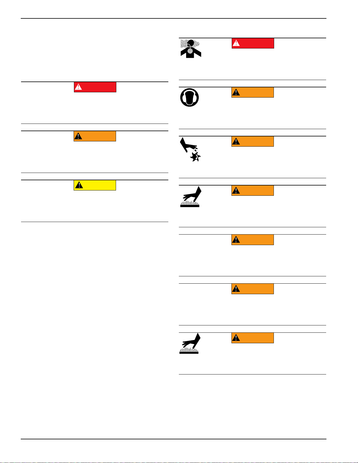
Asphyxiation. Running engines produce
carbon monoxide, a colorless, odorless,
poisonous gas. Carbon monoxide, if not
avoided, will result in death or serious injury.
(000103)
DANGER
(000107)
WARNING
Hearing Loss. Hearing protection is
recommended when using this machine.
Failure to wear hearing protection could
result in permanant hearing loss.
(000111)
WARNING
Moving Parts. Keep clothing, hair, and
appendages away from moving parts. Failure
to do so could result in death or serious injury.
(000108)
WARNING
Hot Surfaces. When operating machine, do not
touch hot surfaces. Keep machine away from
combustibles during use. Hot surfaces could
result in severe burns or fire.
(000182a)
WARNING
Equipment damage. Only qualified service personnel may
install, operate, and maintain this equipment. Failure to follow
proper installation requirements could result in death, serious
injury, and equipment or property damage.
WARNING
Risk of injury. Do not operate or service this machine
if not fully alert. Fatigue can impair the ability to service
this equipment and could result in death or serious
injury.
(000215)
(000139)
WARNING
Risk of burns. Allow engine to cool before
draining oil or coolant. Failure to do so could
result in death or serious injury.
Safety Symbols and Meanings
Throughout this publication, and on tags and decals affixed
to the unit, DANGER, WARNING, CAUTION and NOTE
blocks are used to alert personnel to special instructions
about a particular operation that may be hazardous if
performed incorrectly or carelessly. Observe them
carefully. Their definitions are as follows:
General Hazards
NOTE: Notes contain additional information important to
a procedure and will be found within the regular text of
this manual.
These safety alerts cannot eliminate the hazards that they
indicate. Common sense and strict compliance with the
special instructions while performing the action or service
are essential to preventing accidents.
2 Owner’s Manual for MLT4060MVD Light Tower
Page 7
Introduction and Safety
(000105)
DANGER
Explosion and Fire. Fuel and vapors are
extremely flammable and explosive. Add fuel
in a well ventilated area. Keep fire and spark
away. Failure to do so will result in death
or serious injury.
(000147)
WARNING
Risk of Fire. Unit must be positioned in a
manner that prevents combustible material
accumulation underneath. Failure to do so
could result in death or serious injury.
(000110)
WARNING
Risk of Fire. Hot surfaces could ignite
combustibles, resulting in fire. Fire could
result in death or serious injury.
WARNING
Personal injury. Trailer must be securely coupled to
the hitch with the chains correctly attached. Uncoupled
or unchained towing could result in death or serious
injury.
(000233a)
Personal injury. Do not operate unit during transport.
Doing so could result in death, serious injury, or
property damage.
(000231a)
WARNING
(000234a)
WARNING
Crushing hazard. Verify unit is properly secured and
on level ground. An unsecured unit can suddenly roll
or move, causing death or serious injury.
WARNING
Property or Equipment Damage. Tighten wheel lug
nuts after first 50 miles to factory specifications.
Failure to do so could result in death, serious injury,
property or equipment damage.
(000235)
(000145)
DANGER
Electrocution. In the event of electrical accident,
immediately shut power OFF. Use non-conductive
implements to free victim from live conductor. Apply
first aid and get medical help. Failure to do so will
result in death or serious injury.
(000104)
DANGER
Electrocution. Water contact with a power
source, if not avoided, will result in death
or serious injury.
(000144)
DANGER
Electrocution. Contact with bare wires,
terminals, and connections while generator
is running will result in death or serious injury.
(000152)
DANGER
Electrocution. Verify electrical system is
properly grounded before applying power.
Failure to do so will result in death or serious
injury.
(000188)
DANGER
Electrocution. Do not wear jewelry while
working on this equipment. Doing so will
result in death or serious injury.
DANGER
Electrocution. DO NOT use the unit if
electrical cord is cut or worn through. Doing
so will result in death or serious injury.
(000263a)
Explosion and Fire Hazards
Trailer Hazards
Electrical Hazards
Owner’s Manual for MLT4060MVD Light Tower 3
Page 8
Introduction and Safety
(000188)
DANGER
Electrocution. Do not wear jewelry while
working on this equipment. Doing so will
result in death or serious injury.
(000137a)
WARNING
Explosion. Batteries emit explosive gases while charging.
Keep fire and spark away. Wear protective gear when
working with batteries. Failure to do so could result in
death or serious injury.
(000162)
WARNING
Explosion. Do not dispose of batteries in a fire. Batteries
are explosive. Electrolyte solution can cause burns and
blindness. If electrolyte contacts skin or eyes, flush with water
and seek immediate medical attention.
(000163a)
WARNING
Risk of burn. Do not open or mutilate batteries.
Batteries contain electrolyte solution which can
cause burns and blindness. If electrolyte contacts
skin or eyes, flush with water and seek immediate
medical attention.
WARNING
Environmental Hazard. Always recycle batteries at an
official recycling center in accordance with all local
laws and regulations. Failure to do so could result in
environmental damage, death or serious injury.
(000228)
(000192)
DANGER
Explosion and fire. Fuel and vapors are extremely
flammable and explosive. No leakage of fuel is
permitted. Keep fire and spark away. Failure to do
so will result in death or serious injury.
(000174)
DANGER
Risk of fire. Allow fuel spills to completely dry
before starting engine. Failure to do so will
result in death or serious injury.
Battery Hazards
Fuel Hazards
• DO NOT fill fuel tank near an open flame, while
smoking, or while engine is running. DO NOT fill
tank in an enclosed area with poor ventilation.
• DO NOT operate with the fuel tank cap loose or
missing.
Engine Safety
Internal combustion engines present special hazards
during operation and fueling. Failure to follow the safety
guidelines described below could result in severe injury or
death. Read and follow all safety alerts described in the
engine operator's manual. A copy of this manual was
supplied with the unit when it was shipped from the factory.
Always recycle batteries in accordance with local laws and
regulations. Contact your local solid waste collection site
or recycling facility to obtain information on local recycling
processes. For more information on battery recycling, visit
the Battery Council International website at: http://
batterycouncil.org
• DO NOT run engine indoors or in an area with poor
ventilation. Make sure engine exhaust cannot seep
into closed rooms or ventilation equipment.
• DO NOT clean air filter with fuel or other types of
low flash point solvents.
• DO NOT operate the unit without a functional
exhaust system.
• Shut the engine down if any of the following
conditions exist during operation:
• Abnormal change in engine speed.
• Loss of electrical output.
• Equipment connected to the unit overheats.
• Sparking occurs.
• Engine misfires or there is excessive engine/
generator vibration.
• Protective covers are loose or missing.
• Ambient air temperature is above 120°F (49°C).
4 Owner’s Manual for MLT4060MVD Light Tower
Page 9

Introduction and Safety
WARNING
Personal Injury. Do not use lifting hook if there are
signs of damage or corrosion. Doing so could result
in death, serious injury, or property damage.
(000349)
WARNING
Personal Injury. Do not use lifting hook other than as
directed. Failure to do so could result in death, serious
injury, or property damage.
(000350)
(000260a)
High Voltage. Verify area above unit is clear
of overhead wires and obstructions. Contact
with high-voltage power lines will result in
death or serious injury.
DANGER
DANGER
Electrocution. DO NOT use the unit if
electrical cord is cut or worn through. Doing
so will result in death or serious injury.
(000263a)
Operating Safety
Lifting the Unit
Positioning the Unit
•
The area immediately surrounding the unit should
be dry, clean, and free of debris.
• Position and operate the unit on a firm, level
surface.
• If the unit is equipped with a frame grounding stud,
follow any local, state, and National Electrical Code
(NEC) guidelines when connecting.
Starting the Unit
• Verify the trailer hitch and the coupling are
compatible. Make sure the coupling is securely
fastened to the vehicle.
• DO NOT tow trailer using defective parts. Inspect
the hitch and coupling for wear or damage.
• Connect safety chains in a crossing pattern under
the tongue.
• Before towing the trailer, verify the weight of the
trailer is equal across all tires. On trailers with
adjustable height hitches, adjust the angle of the
trailer tongue to keep the trailer as level as
possible.
Running Lights
Verify directional and brake lights on the trailer are
connected and working properly.
Wheels and Tires
•
Check trailer tires for wear and proper inflation.
• Verify wheel lug nuts are present and tightened to
the specified torque.
Safe Towing Techniques
•
Practice turning, stopping and backing up in an
area away from heavy traffic prior to transporting
the unit.
• Maximum recommended speed for highway towing
is 45 mph (72 km/h). Recommended off-road
towing speed is 10 mph (16 km/h) or less,
depending on terrain.
• When towing, maintain extra space between
vehicles and avoid soft shoulders, curbs and
sudden lane changes.
DO NOT start a unit in need of repair.
•
Towing Safety
Towing a trailer requires care. Both the trailer and vehicle
must be in good condition and securely fastened to each
other to reduce the possibility of an accident. Some states
require that large trailers be registered and licensed.
Contact your local Department of Transportation office to
check on license requirements for your particular unit.
Hitch and Coupling
•
Verify the hitch and coupling on the towing vehicle
are rated equal to, or greater than, the trailer's
Gross Vehicle Weight Rating (GVWR).
Owner’s Manual for MLT4060MVD Light Tower 5
Tandem Towing Safety
This unit is equipped with a tandem tow hitch. This
feature allows the operator to tow a second
MLT4060MVD Light Tower behind the unit.
• Do not use the tandem tow hitch to tow any other
equipment other than a second MLT4060MVD
• Local regulations may limit or prohibit tandem
towing. There may be restrictions on towing speed,
overall vehicle length, the types of roads on which
the units can be towed, and which road lanes are
permissible for towing vehicles. Check with the
local authority having jurisdiction (for example, the
state Department of Transportation) before using
the tandem tow hitch.
• Connect the second MLT4060MVD using the same
procedures and preventative safety measures as
required for a single unit.
Page 10

Introduction and Safety
Reporting Trailer Safety Defects
If you believe your trailer has a defect which could cause
a crash or could cause injury or death, you should
immediately inform the National Highway Traffic Safety
Administration (NHTSA) in addition to notifying Generac
Mobile Products LLC.
If NHTSA receives similar complaints, it may open an
investigation; and if it finds that a safety defect exists in a
group of vehicles, it may order a recall and remedy
campaign. However, NHTSA cannot become involved in
an individual problem between you, your ASD, or Generac
Mobile Products LLC.
To contact NHTSA, you may either call the Auto Safety
Hotline toll-free at 1-888-327-4236 (TTY:1-800-424-9153),
go to http://www.safercar.gov; or write to:
Administrator
NHTSA
1200 New Jersey Avenue S.E.
Washington, DC 20590
You can also obtain other information about motor vehicle
safety from http://www.safercar.gov.
Safety and Operating Decals
See Figure 1-1 and Figure 1-2. This unit features
numerous safety and operating decals. These decals
provide important operating instructions and warn of
dangers and hazards. The following diagrams illustrate
decal locations and descriptions.
Replace any missing or hard-to-read decals and use care
when washing or cleaning the unit. Decal part numbers
can be found in the parts manual at
www.generacmobileproducts.com.
ID Description
A Dangers: General Transport and Operating Safety
B Electric Shock Hazard
C Engine Safety
D Ultra Low Sulfur Diesel
E Forklift and Tie-Down Location
F Towing Instructions
G Cable Winding Instruction
H Lifting Point
J Hot Surface
K Tie-Down Location
L Owner’s Manual Storage Location
M Light Tower Setup Instructions
N Rear Jack Storage
P Position of Stowed Mast
Q Outrigger Retraction Warning
RNot A Step
S Pressurized Coolant Hazard
T Entanglement Hazard
U Cutting Hazard
V Hot Surface Warning: Do Not Remove Grille
W Neutral Bonded To Frame
X Electrical Ground
Y Read Manual Before Operating
Z Disconnect Battery Before Servicing
6 Owner’s Manual for MLT4060MVD Light Tower
Page 11

Introduction and Safety
Figure 1-1. External Decals
Owner’s Manual for MLT4060MVD Light Tower 7
Page 12

Introduction and Safety
ID Description
A Dangers: General Transport and Operating Safety
B Electric Shock Hazard
C Engine Safety
D Ultra Low Sulfur Diesel
E Forklift and Tie-Down Location
F Towing Instructions
G Cable Winding Instruction
H Lifting Point
J Hot Surface
K Tie-Down Location
L Owner’s Manual Storage Location
M Light Tower Setup Instructions
N Rear Jack Storage
P Position of Stowed Mast
Q Outrigger Retraction Warning
RNot A Step
S Hood Lifting Instructions
T Hood Lift Location
U Pressurized Coolant Hazard
V Entanglement Hazard
W Cutting Hazard
X Hot Surface Warning: Do Not Remove Grille
Y Neutral Bonded To Frame
Z Electrical Ground
AA Read Manual Before Operating
BB Disconnect Battery Before Servicing
8 Owner’s Manual for MLT4060MVD Light Tower
Page 13

Introduction and Safety
U
V
W
X
J
Y
Z
B
AA
BB
Figure 1-2. Internal Decals
Owner’s Manual for MLT4060MVD Light Tower 9
Page 14

Introduction and Safety
This page intentionally left blank.
10 Owner’s Manual for MLT4060MVD Light Tower
Page 15
Section 2: General Information
Specifications
DESCRIPTION UNIT OF MEASURE MLT4060MVD
Engine
Make — Mitsubishi
Model — L3E-W464MLD
EPA Tier — Tier 4 Final
Horsepower—Prime hp (kW) 10.5 (7.8)
Horsepower—Standby hp (kW) 12.2 (9.1)
Operating Speed rpm 1,350/1,800
Displacement in3 (L) 57.97 (0.95)
Cylinders quantity 3
Fuel Consumption—Full Load gph (Lph) 0.549 (2.078)
Fuel Consumption—Low Speed (Lights Only) gph (Lph) 0.19 (0.738)
Battery Type—Group Number — 24
Battery Voltage quantity per unit 12 (1)
Battery Rating cold-cranking amps (CCA) 440
Generator
Make — Marathon
Model — 331CSA3018
Type, Insulation — Brushless, F
Generator Set (Engine/Generator)
Output - Standby kW (kVA) 6.0 (6.0)
Output Voltage volts 120/240, single phase
Output Amperes 120V (240V) amperes 50 (25)
Frequency Hz Hertz 60
Power Factor percentage 1 (1Ø)
CSA Listed — Yes
Weights
Dry Weight lb (kg) 1,694 (768)
Operating Weight lb (kg) 2,770 (1,256)
Capacities
Fuel Tank Volume gal (L) 110 (416.4)
Usable Fuel Volume gal (L) 104 (393.7)
Coolant (including engine) qt (L) 4.5 (4.3)
Oil (including filter) qt (L) 5.5 (5.2)
Maximum Run Time
Operating with LED Lights Only hr 533
Operating with LED Lights and Export Power hr 189
®
®
Owner’s Manual for MLT4060MVD Light Tower 11
Page 16
General Information
DESCRIPTION UNIT OF MEASURE MLT4060MVD
Lighting
Lighting Type — Light-Emitting Diode (LED)
Driver (4) — Mean Well HLG-320H-30A
Lumens lm 172,200
AC Distribution
Circuit Breaker Size amperes 30
Voltage Selection — N/A
Voltage Regulation — AVR ± 1%
Voltages Available 1Ø volts 120, 240
Voltages Available 3Ø volts N/A
Trailer
Number of Axles quantity 1
Capacity—Axle Rating lbs (kg) 3,000 (998)
Tire Size in (cm) 13 (33)
Hitch—Standard — 2 in ball
Maximum Tire Pressure psi (kPA) 50 (345)
Specifications are subject to change without notice.
12 Owner’s Manual for MLT4060MVD Light Tower
Page 17
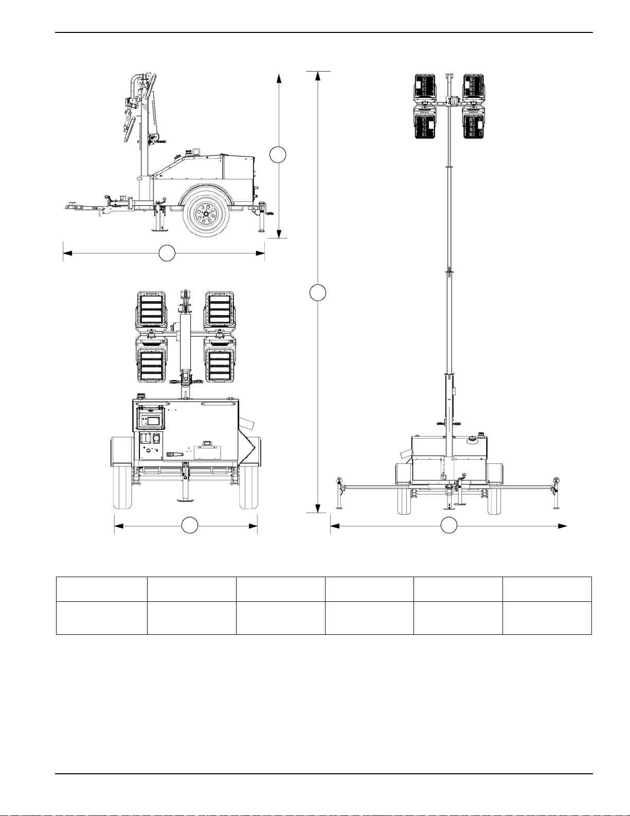
Unit Dimensions
A
B
C
D E
008451
General Information
Figure 2-1. Unit Dimensions
ABCDE
MLT4060MVD
124.5 in
(316.23 cm)
101.2 in
(257.05 cm)
Specifications are subject to change without notice.
23 ft
(7 m)
68.2 in
(173.23 cm)
144.8 in
(367.80 cm)
Owner’s Manual for MLT4060MVD Light Tower 13
Page 18
General Information
TIRE AND LOADING INFORMATION
RENSEIGNEMENTS SUR LES
PNEUS ET LE CHARGEMENT
SEE OWNER’S
MANUAL FOR
ADDITIONAL
INFORMATION
VOIR LE
MANUEL DE
L’USAGER
POUR
PLUS DE
RENSEIGNEMENTS
MANUFACTURED BY/FABRIQUE PAR: GeneracMobile Products, LLC DATE: 00/0000
GVWR/PNBV: 000KG (0000LBS) COLD INF. PRESS./
PRESS. DE
V.I.N./N.I.V.:
00000000000000000
TYPE:
TRAILER
MODEL:
XXX000
GAWR / PNBE TIRE / PNEU RIM / JANTE GONF A FROID - KPA(PSI/LPC) SGL / DUAL
EACH
AXLE
THIS VEHICLE CONFORMS TO ALL APPLICABLE STANDARDS PRESCRIBED UNDER THE U.S. FEDERAL MOTOR VEHICLE SAFETY STANDARDS(FMVSS) AND CANADIAN
MOTOR VEHICLE SAFETY REGULATIONS IN EFFECT ON THE DATE OF MANUFACTURE.
CE VEHICULE EST CONFORME A TOUTES LES NORMES QUI LUI SONT APPLICABLES EN VERTU DU REGLEMENT SUR LA SECURITE DES VEHICULES AUTOMOBILES DU CANADA EN VIGUEUR A LA DATE SA
FABRICATION.
The weight of cargo should never exceed 0000KG (0000LBS)
Le poids du chargement ne doit jamais depasser 0000KG (0000LBS)
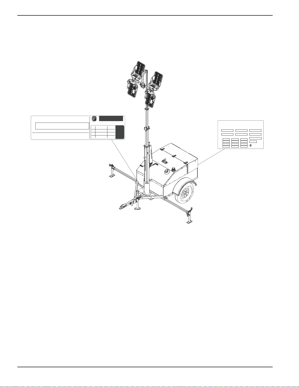
Vin Tag
Unit ID Tag
Located on control box
Serial Number
V
A
Model
KVA
Manufacturing Code
1 ph. 1.0PF 3 ph. .8PF 3 ph. 1.0PF
KW
Country of Origin
Weight (lbs/kg) RPM/Frequency
Rating
Ins. Class
FOR ELECTRICAL EQUIPMENT
ONLY. POUR MATERIAL
ELECTRIQUE SEULEMENT.
209649
Form: SFC626B
Manufactured by GENERAC MOBILE PRODUCTS, LLC
(920) 361-4442 (800) 926-9768
008347
Unit Serial Number Locations
Refer to the illustration to locate the unit ID tag and Vehicle Identification Number (VIN) tag on the unit. Important
information, such as the unit serial number, model number, VIN and tire loading information are found on these tags.
Record the information from these tags so it is available if the tags are lost or damaged. When ordering parts or
requesting assistance, you may be asked to provide this information.
Figure 2-2. Serial Number Locations
14 Owner’s Manual for MLT4060MVD Light Tower
Page 19

Component Locations
A
I
C
D
H
G
F
E
D
C
B
B
B
N
O
P
Q
M
K
J
L
General Information
Figure 2-3. Component Locations
A Fuel fill I Junction box
B Forklift pocket and tie-down point J Lights (4)
C Outrigger jack (2) K Central lift point
D Outrigger (2) L Snow hood
E Tongue jack M Rear jack / Tandem tow hitch receiver
F Tie-down point N Control box
G Rear jack storage O Engine access
H Mast rotation knob P Fuel level warning beacon
QWinch
Owner’s Manual for MLT4060MVD Light Tower 15
Page 20
General Information
A
M
K
J
I
H
G
F
E
D
C
L
B
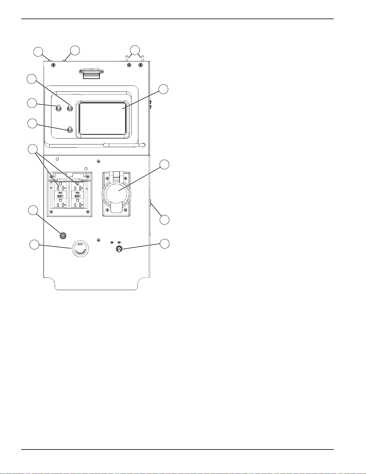
Control Panel
(E) 240V/30A Twist-Lock Receptacle (or 240V/30A RV
Receptacle, if equipped)
Customer convenience outlet for connecting auxiliary
equipment such as fans, pumps and drills.
(F) 120V Breakers (2)
Provides circuit protection for the 120V/20A GFCI outlet.
(G) 240V Breaker
Main disconnect and circuit protection for the 240V/30A
twist-lock and 120V GFCI receptacles.
(H) Emergency Stop Button
Stops the engine immediately in an emergency. For more
information, see Emergency Stop.
(I) Ground Stud
An electrical grounding stud for connecting an earth
ground to the unit if required. Follow local, state, or
National Electric Code (NEC) guidelines.
(J) 120V/20A GFCI Receptacle
Customer convenience receptacle for use in connecting
auxiliary equipment such as fans, pumps, drills. Includes
a GFCI test and reset button.
Figure 2-4. Control Panel
Control Panel Features and Functions
(A) DC Circuit Breaker
Resets the DC electrical circuit that powers the control
panel and engine components.
(B) Driver Return Line Breaker (DRLB)
Protects all four drivers.
(C)
Mast Light Circuit Breakers (2)
Circuit breakers for the LED light fixtures.
(K) Mast Switch (electric winch units only)
Raises and lowers the mast on units equipped with an
electric winch.
(L) Automatic Load Sense Switch
Automatic Load Sense works in tandem with the
ECOSpeed engine to adjust engine operating speed
according to lighting and export power requirements. The
240VAC receptacle breaker (F) must be ON to enable
Automatic Load Sense.
• Turning Automatic Load Sense switch ON
enables Automatic Load Sense—the default
setting for normal export power operation.
• Turning Automatic Load Sense switch OFF
disables Automatic Load Sense and allows the
engine to run at high speed when the 240VAC
outlet breaker (H) is ON. Use this setting when
connecting equipment that requires a higher
starting amperage, such as air conditioners, air
compressors, or submersible pumps.
(M) Control Power Switch
Enables power supply to the Power Zone–DLA.
(D)
PowerZone®–DLA
This controller serves as the main control unit for the
Light Tower. See the following pages for details.
16 Owner’s Manual for MLT4060MVD Light Tower
Page 21
General Information
C
A
B
ECOSpeed™ Engine
This unit is equipped with an ECOSpeed engine that runs
at variable speeds depending on the applied operational
load. Operating temperature remains constant regardless
of engine speed or applied loads.
Refer to Operation for more information.
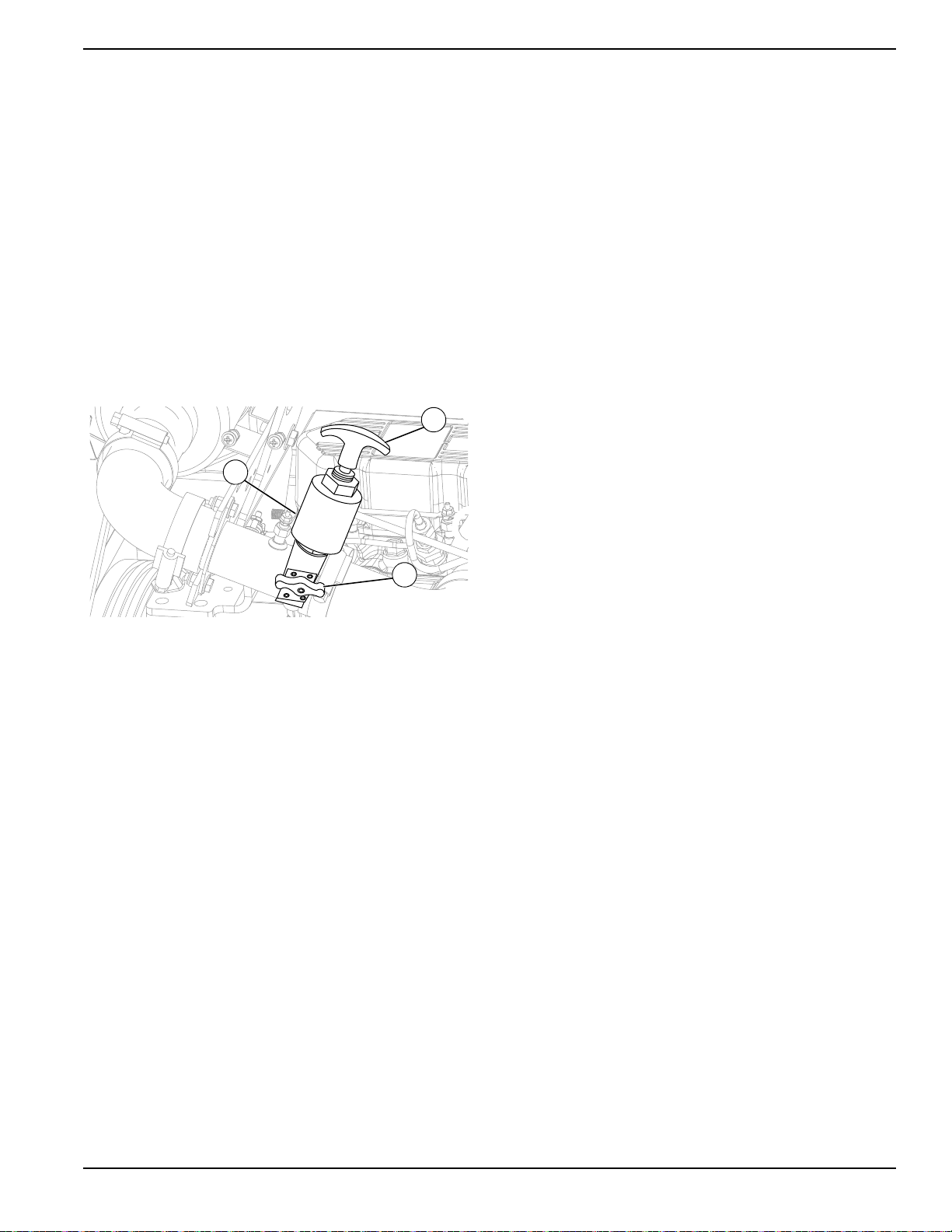
Positive Air Shutdown (PAS) (if equipped)
See Figure 2-5. This unit may be equipped with a
positive air shutdown (A) on the air intake. The PAS
system automatically stops the engine if speed exceeds
2100 rpm. Engine overspeed can occur if the
atmosphere contains elevated levels of combustible
propane or natural gas.
valve does not close, contact Generac Mobile
Products Technical Support.
Reset the PAS
IMPORTANT NOTE: Before resetting the PAS, turn the
Control Power switch OFF (O). This will prevent
unexpected engine start-up during the procedure.
1. Rotate the reset knob (C) and hold it in place while
pulling the T-handle until knob rotates counterclockwise into plunger detent. An audible “click”
indicates the knob has seated properly
2. Verify that the knob is parallel to the intake pipe
centerline.
3. Release T-handle, and then release knob. Knob
should remain parallel to the intake pipe centerline.
Lower Radiator Hose Heater (if equipped)
Use and Maintenance
The lower radiator hose heater is designed to enable
engine start-up in extreme cold weather conditions by
warming the engine coolant. While the heater is designed
to be operated overnight if necessary, two to five hours of
heating just prior to starting is usually sufficient for proper
engine starting.
Figure 2-5. Positive Air Shutdown
The PAS system stops the engine by closing an internal
valve and obstructing intake air. Shutdown is triggered
automatically by an output from the controller, manually
by pulling the T-handle (B), or by pressing the emergency
stop button on the control panel.
The reset knob (C) rotates 90 degrees to block airflow. If
the knob is parallel to the pipe centerline (as shown), the
valve is open. If the knob is perpendicular to the pipe
centerline, the valve is closed and airflow is blocked.
Test the PAS
Test the PAS at least once a month to ensure optimal
valve performance.
Verify the engine is OFF before testing the PAS.
There are two methods of testing. NOTE: The main
power and controller must be ON for each method.
1. Pull the T-handle. (NOTE: The valve must be open
before testing.)
2. Press the emergency stop button. Testing the PAS
triggers an actuator, closing the butterfly valve
inside the valve body. An audible click can be
heard when the actuator engages. Confirm that the
valve is closed by verifying that the knob has
rotated perpendicular to the pipe centerline. If
NOTE: Use the lower radiator hose heater only in its
designated location. Improper use can damage the
engine.
Perform the following steps when operating a unit
equipped with a lower radiator hose heater.
1. Verify the unit is level so as to maintain proper
orientation of the heater while it is in operation.
2. Verify the cooling system is full of the proper
mixture of water and engine coolant before each
heater use.
3. Use only an undamaged, outdoor rated, three-
prong grounded 120VAC extension cord with a
minimum amperage rating of 10A. Connect the
cord to a properly grounded 120VAC, GFCI outlet.
4. Before starting the engine, unplug the extension
cord from the power first, then unplug the heater
cord set from the extension cord.
Diesel Fired Block Heater
See Figure 2-6. A diesel fired block heater is located
inside the cabinet. Coolant is drawn through the heater
by an internal electric pump, and warmed by a dieselfueled burner. Heated coolant is then circulated through
the engine block and returned to the heater where the
cycle is repeated.
Owner’s Manual for MLT4060MVD Light Tower 17
Page 22

General Information
008576
A
A
004430
A
Heated Fuel Filter (if equipped)
See Figure 2-7. An optional heated fuel filter (A)
prevents diesel fuel from gelling in extremely cold
temperatures. Heating cycles are automatically
controlled by the Power Zone–DLA.
Figure 2-6. Diesel Fired Block Heater
The diesel fired block heater operates automatically
when the unit is set to “dusk to dawn” mode. The heater
does NOT operate when the unit is manual mode. The
keep run switch is a separate option that can not be used
in conjunction with the diesel fired block heater. See
Preparing for Start-Up for more information about unit
operating modes.
NOTE:
The controller initiates the start sequence when
the heater reaches a coolant temperature of 86°F (30°C),
See
Start Sequences
for more information about the unit
start sequence.
Battery Disconnect (if equipped)
See Figure 2-8. This unit may be equipped with a battery
disconnect switch (A). This lockable switch temporarily
removes the battery from the unit electrical circuit without
actually disconnecting the battery cables.
NOTE: A padlock is not included with this unit and must
Heater Lockout Reset Procedure
be supplied by the customer.
Three engine start attempts will trigger a shutdown error
and the controller will need to be reset. Afterwards, the
controller can be restarted and tried again for another
three crank attempts. The controller can be reset as
many times as needed.
The heater may also enter the lockout mode after
experiencing an overheat condition.
The following procedure will clear the lockout mode and
reset the heater for normal operation:
1. Remove fuse F1 (15 Amp). See Wiring Diagrams
for identification.
2. Wait 10 seconds with the fuse out to prepare the
control unit for resetting.
3. Reinsert fuse F1.
4. Wait 10 seconds then turn the heater on using the
On/Off switch or the Instant On button on the
optional timer.
5. Wait 10 seconds after turning the heater on and
remove fuse F1.
6. Wait 30 seconds and then turn the heater off at the
Telemetry (if equipped)
The digital telemetry option enables the operator to
remotely monitor the location, run status, and fuel level of
the equipment. A transmitter inside the unit sends realtime status information to the user, through a cellular or
satellite connection.
switch or optional timer.
7. Wait 3 to 10 seconds after shutting off the heater
than reinsert fuse F1.
8. Wait 10 second then turn the heater back on.
The lockout mode should now be canceled and the
heater operating normally.
18 Owner’s Manual for MLT4060MVD Light Tower
Figure 2-7. Heated Fuel Filter
Figure 2-8. Battery Disconnect
Page 23

Spark Arrester (if equipped)
Select
H
G
F
E
A
B
C
D
A spark arrester, installed on the engine exhaust, may be
required by code in certain municipalities. Check with the
local authority having jurisdiction to determine whether or
not a spark arrester must be installed on the unit before
operation.
Figure 2-9. Power Zone–DLA Layout
General Information
Controller Features and Functions
(A) The Liquid Crystal Display (LCD) Window
This window displays the various operating screens. By
viewing these screens, the operator can monitor both the
engine and generator status while the unit is running.
(B) Select LED
This LED illuminates when the unit is running in AUTO
mode.
(C) Start LED
This LED illuminates when the unit is running in MANUAL
mode.
(D) Start Button
This button starts the engine if there are no shutdown
errors and the engine is in “ready to start” status.
(E) Stop Button
This button shuts down the unit and puts the controller into
STOP mode, whether in MANUAL mode or AUTO mode
NOTE: To prevent damage to the generator and
connected equipment, remove all loads from the
generator by opening all circuit breakers (turn to the OFF
[O] position) before pressing the stop button.
(F) Stop LED
This LED illuminates when the unit is in STOP mode and
flashes when an Electrical Trip and Shutdown Fault has
occurred.
.
(G) Select Button
The select button navigates between AUTO and
MANUAL modes.
(H) Menu Navigation
These buttons (↑, ↓) are used to navigate through the
various operator screens.
Operator Screens
See Figure 2-10. The operator screens display the most
relevant and critical information an operator will need to
properly configure and use the unit. From these six
screens, the operator can access information necessary
to operate the unit under normal conditions.
Figure 2-10. Operator Screens
Power Zone–DLA
See Figure 2-9. The Power Zone–DLA (Digital Light
Tower Autolight) is an auto start controller that monitors
the unit and indicates operational status and fault
Owner’s Manual for MLT4060MVD Light Tower 19
Page 24

General Information
002355
conditions. The controller can be programmed to
automatically start or stop based on time schedule, fault
condition, or load demand.
The controller constantly monitors vital generator and
engine functions for a number of preprogrammed alarm
and fault conditions. When a fault condition occurs, the
engine will be shut down automatically and the LCD
window will show the fault that caused the shutdown. To
resume operation, the fault condition must be corrected.
This controller also records a history of unit performance,
which may be viewed at any time and will not be lost
when the controller is powered down.
Home Screen
See Figure 2-11. The Home screen is the default screen
of the controller and displays after the controller is
powered up and the unit management software is
loaded. It displays the controller mode, total operating
hours, hours left until the next service interval, engine
operating status, and engine RPM. If the unit is in AUTO
mode, the Home screen may also display whether the
scheduler or “dusk to dawn” are enabled.
• TEMP: Displays engine coolant temperature.
Normal operating temperature of the unit is
between 100-230°F (38-110°C).
Lights Screen
See Figure 2-13. The Lights screen enables the operator
to turn the lights on and off. Refer to Light Operation for
more information.
Figure 2-13. Lights Screen
Figure 2-11. Home Screen
Engine Screen
• See Figure 2-12. The Engine screen displays
battery voltage, oil pressure, coolant temperature
and fuel level.
Figure 2-12. Engine Screen
Dusk to Dawn Screen
NOTE: This feature will only work in AUTO mode.
See Figure 2-14. The Dusk to Dawn screen enables or
disables the “dusk to dawn” function. This function uses a
photo sensor to detect the surrounding light level,
automatically starting the engine and turning the lights on
at dusk. The engine will run and the lights will remain
illuminated until dawn.
For instructions on using the Dusk to Dawn feature, see
Dusk to Dawn Sensor.
• VBAT: Displays engine battery voltage while
running. A normal reading is 13.5-15V on 12 volt
systems.
• OIL: Displays engine oil pressure. Normal
operating pressure is between 35-80 psi (241-552
NOTE: This feature will only work in AUTO mode and
with a photo sensor.
kPa).
20 Owner’s Manual for MLT4060MVD Light Tower
Figure 2-14. Dusk to Dawn Screen
Page 25

General Information
Scheduler Screen
See Figure 2-15. The Scheduler screen enables the
operator to program specific times for the lights to turn on
and off. Once programmed, the Scheduler will start the
engine and illuminate the lights until the designated
shutdown time.
Figure 2-15. Scheduler Screen
NOTE: This feature will only work in AUTO mode.
Maintenance Screens
See Figure 2-16. The information displayed on the
maintenance screens can be used to identify, diagnose
and troubleshoot unit shutdown conditions and poor unit
performance.
Figure 2-16. Maintenance Screen
Icon Description
Home screen
Alarms screen
Maintenance screen
Event log screen
2. To select the required icon, press the ↑ button to
cycle right and the ↓ button to cycle left until the
desired operator screen section is reached.
3. Once the desired icon is at the top, press the
Select () button to enter that operator screen
section.
NOTE: Every time the operator screens are entered, the
home icon will be located at the top of the screen.
Alarms Screen
See Figure 2-17. The Alarms ( ) screen displays all the
alarms, warnings, and engine Diagnostic Trouble Code
(DTC) faults. When an alarm occurs, the controller
automatically switches to this screen and remains there
until the alarm is cleared. The Stop LED also flashes.
Figure 2-17. Alarms Screen
• Warnings are non-critical alarm conditions and do
not affect the operation of the generator system.
They serve to draw the operator’s attention to an
undesirable condition. By default, warning alarms
are self-resetting when the fault condition is
removed.
• Electrical trips stop the generator in a controlled
manner. On initiation of the electrical trip condition,
the controller de-energizes all the outputs,
including the lights, to remove the load from the
generator. Once this has occurred, the controller
starts the cooling timer and allows the engine to
cool off-load before shutting down the engine.
• Shutdown alarms stop the generator immediately.
On initiation of the shutdown condition, the
controller de-energizes all the outputs, including
the lights, to remove the load from the generator.
Once this has occurred, the controller shuts the
generator set down immediately to prevent further
damage.
About screen
To enter the navigation menu, use the following
procedure:
1. Press both the ↑ and ↓ buttons simultaneously.
Owner’s Manual for MLT4060MVD Light Tower 21
Page 26

General Information
DTC faults are displayed by the controller.
Table 2-1. Possible DTC Faults
Fault DTC Description
Check Engine
Fault
Low Oil Pressure
Underspeed
Overspeed
Low Fuel Level
Battery Under/
Over Voltage
A fault not recognized by the controller
has been detected. Contact the engine
manufacturer for support.
Engine oil pressure has fallen below
its configured low oil pressure alarm
level.
Engine speed has fallen below its
configured underspeed alarm level.
Engine speed has risen above its
configured overspeed alarm level.
Engine’s fuel level has fallen below its
configured low fuel level alarm.
Engine’s DC supply has fallen below
or risen above its configured alarm
level.
To view the active alarms, repeatedly press the ↑ and ↓
buttons until the LCD window displays the alarm.
Continue to press the ↑ and ↓ buttons to cycle through
the alarms.
To exit the alarm screen, press the ↑ and ↓ buttons
simultaneously to enter the navigation menu. Once
entered, cycle to the desired operator screen.
Line Amperage Screen
See Figure 2-20. Displays AC output amperage in amps
(A). The load balance for each line (L1 and L3) is
displayed in both numerical and graphical form. It is
important to maintain a balanced load distribution
between the lines for optimum generator performance. .
Figure 2-18. Line Amperage Screen
Generator Screen
See Figure 2-19. Displays the average line voltage
frequency (Hertz) and power factor for the generator
while in operation.
NOTE: The alarm condition must be corrected before a
reset will take place. If the alarm condition remains, it is
not possible to reset the unit. The exception to this is the
Low Oil Pressure alarm and similar ‘active from safety on’
alarms, as the oil pressure is low with the engine at rest.
To clear alarms that stop the generator, refer to
Resetting Maintenance Alarms.
NOTE: The LCD backlight is on if the unit has sufficient
voltage while the unit is turned on, unless the unit is
cranking. In this case, the backlight is turned off.
If the controller is left in STOP mode for a period of
inactivity, the controller enters POWER SAVE mode. To
‘wake’ the controller, press the Stop (O) button.
Figure 2-19. Generator Screen
Maintenance Screen
Maintenance Screen
See Figure 2-20. The Maintenance screen ( ) displays
the maintenance alarms configured into the controller.
The three alarms are for servicing the fuel filter, oil filter,
and air filter.
Figure 2-20. Maintenance Screen
22 Owner’s Manual for MLT4060MVD Light Tower
Page 27

General Information
Event Log Screen
See Figure 2-21. The controller’s event log ( ) displays
a list of the last 15 recorded electrical trips or shutdown
events and the engine hours at which they occurred.
Once the log is full, any subsequent electrical trip or
shutdown alarm overwrites the oldest entry in the log.
Therefore, the log always contains the most recent
shutdown alarms.
Figure 2-21. Event Log Screen
To view the event log:
1. Press both ↑ and ↓ buttons simultaneously to
display the navigation menu.
2. Cycle to the event log section and press the Auto
button to enter.
3. Repeatedly press the ↑ or ↓ buttons until the LCD
window displays the desired event.
Continuing to press down the ↑ or ↓ buttons will cycle
through past alarms. Eventually the most recent alarm
will display and the cycle begins again.
To exit the event log, press the ↑ and ↓ buttons
simultaneously to enter the navigation menu. Once
entered, cycle to the desired operator screen.
About Screen
See Figure 2-22. The About ( ) screen contains
information about the controller such as the controller’s
date and time, the product and USB identification
number, and the application and engine version.
Figure 2-22. About Screen
Owner’s Manual for MLT4060MVD Light Tower 23
Page 28

General Information
This page intentionally left blank.
24 Owner’s Manual for MLT4060MVD Light Tower
Page 29

Section 3: Operation
HANDLE
DETAIL E
DETAIL C
DETAIL G
DETAIL H
Rear of Unit
H
J
G
B
D
E
G
A
C
F
(000260a)
High Voltage. Verify area above unit is clear
of overhead wires and obstructions. Contact
with high-voltage power lines will result in
death or serious injury.
DANGER
Light Tower Setup
Figure 3-1. Set Up Outriggers and Jacks
4. A grounding stud (C) is located on the control box.
For grounding requirements, follow any local, state,
or National Electrical Code (NEC) guidelines.
5. See Detail E. Pull the locking pin (D) on the
outrigger (E) and pull each outrigger out until the
spring loaded locking pin snaps back into place.
Pull the locking pin on the outrigger jack and rotate
each jack 90° so the jack pad is facing down.
1. For maximum light coverage, position the unit at
ground level or in a spot higher than the area being
illuminated by the lamps.
NOTE: The mast extends up to 23 ft (7 m).
2. See Figure 3-1. Place the unit on firm ground that
is relatively flat, and then block the wheels (A) to
keep it from moving. This will make it easier to level
the unit.
3. Pull the locking pin (B) on the tongue jack and
rotate the jack 90°. Reinstall the locking pin. Turn
the jack handle clockwise to raise the trailer tongue
Reinstall the locking pin.
6. Pull the locking pin on the rear jack (F) and rotate
the jack 90°. Reinstall the locking pin. Rotate the
jack handle clockwise to start leveling the trailer
(see Detail G). Adjust all four jacks by rotating their
handles (G) clockwise until they are firmly in
contact with the ground and the trailer is as level as
possible.
7. See Detail H. Before raising the mast, it may be
necessary to adjust the lamps. The lamps may be
adjusted up, down, left or right by simply aiming
them in the desired direction.
off of the towing vehicle.
Owner’s Manual for MLT4060MVD Light Tower 25
Page 30

Operation
004037
SAE 30W
SAE 40W
SAE 10W
SAE 15W-40
SAE 0W-20 Synthetic
(below -0°F / -18°C)
(000135)
CAUTION
Engine damage. Verify proper type and quantity of
engine oil prior to starting engine. Failure to do so
could result in engine damage.
CAUTION
(000323)
Engine damage. Use approved coolant only.
Failure to do so could result in equipment damage.
(000100a)
WARNING
Consult Manual. Read and understand manual
completely before using product. Failure to
completely understand manual and product
could result in death or serious injury.
Fuel Recommendations
IMPORTANT: DO NOT use home heating oil or bio-
diesel fuel.
Use No. 2D diesel fuel when temperatures are above
freezing. When temperatures are below freezing, blend
No. 1D diesel fuel and No. 2D diesel fuel together (50/50
ratio) to adjust for the ambient temperature.
Diesel fuel must also meet the following requirements:
• Sulfur content of 15 parts per million (ppm)
maximum
• Minimum Cetane index of 40.
NOTE: Low ambient temperatures as well as operation
at high altitudes may require the use of fuels with higher
Cetane ratings.
Engine Oil Recommendations
To maintain the product warranty, the engine oil should
be serviced in accordance with the recommendations of
this manual. Refer to Figure 3-2.
Coolant Recommendations
Improper coolant can damage the engine cooling system.
Use demineralized water or distilled water for best results.
Hard water causes scale deposits, which reduces cooling
efficiency and raises internal temperatures, possibly leading
to engine damage. Use an anti-corrosive to prevent rot in
summer and anti-freeze to prevent freezing in winter.
Standard Units
The use of a long-life ethylene glycol coolant (LLC) at
60% concentrate. (40% water) is recommended. When
operating in ambient temperatures above 0°F (-18°C),
use a 50/50 ratio.
Cold Climate / Arctic Package Units
The cooling system is pre-filled with extended-life
ethylene glycol coolant blend (60/40) rated for heavy duty
use to a maximum freezing point of –62°F (–52°C).
Prestart Checklist
Before starting the unit, all items in the prestart checklist
must be completed. This checklist applies to both manual
and remote starting of the unit.
Verify all maintenance procedures are up to date. For
more information, refer to General Maintenance and
Table 4-1.
Figure 3-2. Engine Oil Recommendations
26 Owner’s Manual for MLT4060MVD Light Tower
Level the unit.
Verify the unit is dry. Look for water inside or near the
unit; dry if needed.
For grounding requirements, follow any local, state,
or National Electrical Code (NEC) guidelines.
Verify the Control Power switch is OFF (O).
Verify all circuit breakers are OFF (O).
Verify that the Emergency Stop Switch is pulled out.
Verify that the Positive Air Shutdown (PAS) (if
equipped) is reset.
Inspect all electrical cords; repair or replace any that
are cut, worn, or bare.
Page 31

Operation
DANGER
Electrocution. DO NOT use the unit if
electrical cord is cut or worn through. Doing
so will result in death or serious injury.
(000263a)
WARNING
(000266)
Tipping hazard. Extend the outriggers and level the unit
before raising the mast. Keep the outriggers extended while
the mast is up. Failure to do so could cause the unit to tip
and fall and could result in death or serious injury.
WARNING
Tipping hazard. Do not extend the mast beyond the
colored mark on the second mast section. The unit
can become unstable and tip or fall, causing injury.
(000262)
WARNING
Personal Injury. Stop immediately if the mast hangs
up or the winch cable develops slack. Excess slack
could cause the mast to collapse, resulting in personal
injury or equipment damage.
(000265)
DETAIL B
STOP
A
B
C
008414
Verify all winch cables are in good condition and
centered on each pulley. Do not use if cables are
kinked or beginning to unravel.
Check oil, coolant, and fuel levels. For more
information, refer to General Maintenance.
Verify battery connections are secure.
Check the engine fan belt tension and condition.
Check the engine fan belt guard.
Check the engine exhaust system for loose or rusted
components.
Verify all covers are in place and secure.
Turn the battery disconnect switch ON (if equipped).
Raising Mast—Manual Winch
IMPORTANT NOTE: The mast is intended for use
ONLY to support the LED fixtures. Do not use the
mast as a hoist or for any other purpose.
1. Set up and level the unit. See Light Tower Setup.
.
2. See Figure 3-3. Check the mast cables for
excessive wear or damage. Make sure the cables
are properly centered in each pulley (A). Check the
coiled electrical cord for damage.
3. Rotate the mast by loosening the mast rotation
knob (C) at the bottom of the mast. Turn the mast
until the lights face in the desired direction, and
then tighten the mast rotation knob to secure the
mast in position.
4. See Figure 3-3.
the mast, making sure that the coiled electrical cord
is extending at the top sections of the mast. STOP
extending the mast when the colored mark on the
second mast section is visible as seen in Detail B.
IMPORTANT NOTE: Contact an ASD immediately if
the mast hangs up or the winch cable develops
slack.
Owner’s Manual for MLT4060MVD Light Tower 27
Use the winch (B) to slowly extend
Figure 3-3. Winch and Pulley Locations—Manual
Page 32

Operation
DANGER
Electrocution. DO NOT use the unit if
electrical cord is cut or worn through. Doing
so will result in death or serious injury.
(000263a)
WARNING
(000266)
Tipping hazard. Extend the outriggers and level the unit
before raising the mast. Keep the outriggers extended while
the mast is up. Failure to do so could cause the unit to tip
and fall and could result in death or serious injury.
DETAIL B
DETAIL C
STOP
A
B
C
WARNING
Tipping hazard. Do not extend the mast beyond the
colored mark on the second mast section. The unit
can become unstable and tip or fall, causing injury.
(000262)
WARNING
Personal Injury. Stop immediately if the mast hangs
up or the winch cable develops slack. Excess slack
could cause the mast to collapse, resulting in personal
injury or equipment damage.
(000265)
Raising Mast—Electric Winch (if equipped)
IMPORTANT NOTE: The mast is intended for use
ONLY to support the LED fixtures. Do not use the
mast as a hoist or for any other purpose.
1. Set up and level the unit. See Light Tower Setup.
2. See Figure 3-4. Check the mast cables for
excessive wear or damage. Verify the cables are
properly centered in each pulley (A). Check the
electrical cord for damage.
3. Rotate the mast by loosening the mast rotation
knob at the bottom of the mast (C). Turn the mast
until the lights face in the desired direction and
then tighten the mast rotation knob to secure the
mast in position.
NOTE: Power must be on for the winch control to
operate.
4. Press and hold the winch control switch (B; Detail
B) upward to telescope the mast to the desired
height. Extend the mast slowly, and verify the
coiled electrical cord is extending at the top
sections of the mast.
when the colored mark on the second mast section
is visible as seen in Detail C.
IMPORTANT NOTE: A limit switch on the main mast
section will disconnect power to the upper electric
winch to prevent overextending the mast.
STOP extending the mast
Figure 3-4. Switch & Pulley Locations - Electric Winch
28 Owner’s Manual for MLT4060MVD Light Tower
IMPORTANT NOTE: Contact an ASD immediately if
the mast hangs up or the winch cable develops
slack.
Page 33

Preparing for Start-Up
NOTE:
drained, it may be necessary to bleed the fuel lines before
starting. Refer to the engine manual supplied with the unit.
NOTE:
fuel, it may be necessary to cycle the diesel fired block
heater for a few minutes. before starting. See
Block Heater
Select AUTO Mode or MANUAL Mode
See Figure 3-5. Use the select button to navigate
between AUTO and MANUAL mode on the Home
screen.
If the engine was run out of fuel or the fuel tank was
On initial start-up, or if the engine was run out of
Diesel Fired
in Section 2.
• AUTO mode is required for programming
automatic start and stop times (see Scheduler
Screen), or enabling the “Night Watchman” sensor
(see Dusk to Dawn Screen.)
• MANUAL mode is used for on-demand control of
the lights and convenience outlets.
Table 3-1.
Engine Speed
Selection
240VAC
Outlet
Breaker
ON (i)
OFF (O) Low speed
*Engine will speed up automatically when more
power is drawn from receptacles.
Load Sense Switch
ON (I) OFF (O)
Load
dependent—
variable speed*
Operation
High speed
1800 rpm
Low speed
1350 rpm
Figure 3-5. Selecting MANUAL or AUTO Mode
LED Lights Only
Turn the 240V outlet breaker OFF. The engine will run at
low speed while operating, greatly reducing sound
emissions and fuel consumption.
LED Lights and Export Power
Turn the 240V outlet breaker ON and Load Sense OFF.
The engine will run at high speed for powering high
amperage equipment.
LED Lights and Export Power with Load Sense
Turn the 240V outlet breaker ON and Load Sense ON.
The engine will run at high speed when detecting applied
load(s) such as hand tools and low amperage equipment.
Table 3-1 illustrates the four possible combinations of
240V outlet breaker and Load Sense switch positions.
Owner’s Manual for MLT4060MVD Light Tower 29
Page 34

Operation
Turn Power
Switch On
Manual or
Auto Mode
Press Select Button
Manual
Auto
Press Green Start
Button
Dusk to Dawn Mode
ON
Scheduler Mode ON
Controller Reads Dusk
to Dawn Sensor
Start T ime
Dark
No
No
Yes
Yes
Display: "Start Delay"
(5 Seconds)
Display: "Pre-Heat"
(10 Seconds)
Glow Plugs Energize
Display: "Cranking"
(15 Seconds)
Starter Energizes
Generator
Frequency>28 Hz
Controller verifying
engine speed
Display: "Cranking Rest"
(15 Seconds)
Display: "Loss of Crank Disconnect"
Starter De-energizes
Fuel Pump De-energizes
"Crank Attempts" greater
than or equal to 3?
Fuel Pump Energizes
No
END
Display: "Safety On"
(30 seconds)
Generator
Frequency>0 Hz
Controller verifying
engine speed
Display "Shutdown
Failed to Start"
Press Select Button and Clear Alarm
Manual or
Auto Mode
Manual
Lights T urn On
Manually Select Lights
to Enable
Lights T urn On
Controller Monitors Status Controller Monitors Status
No
Yes
Yes
No
Yes
Auto
Pin 30 on
Controller
Receives Ground
Signal
to ST AR T
Display: "Starting"
(10 Seconds)
008717
Start Sequences
This section contains diagrams of the various start sequences.
Standard Units
30 Owner’s Manual for MLT4060MVD Light Tower
Page 35

Units with Diesel Fired Block Heaters
Turn Power
Switch On
Manual or
Auto Mode
Press Select Button
Manual
Auto
Press Green Start
Button
Dusk to Dawn Mode
ON
Scheduler Mode ON
Controller Reads Dusk
to Dawn Sensor
Start Time
Dark
No
No
Pin 30 on
Controller
Receives Ground
Signal
to START
Yes
Yes
Display: "Loss of Crank Disconnect"
END
Display: "Safety On"
(30 seconds)
Generator
Frequency>0 Hz
Controller verifying
engine speed
Display "Shutdown
Failed to Start"
Press Select Button and Clear Alarm
Manual or
Auto Mode
Manual
Lights Turn On
Manually Select Lights
to Enable
Lights Turn On
Controller Monitors Status Controller Monitors Status
Yes
No
Yes
Auto
Block Heater
Ignites
Yes
Coolant Heats to 86°F
Consecutive
Ignite Attempts
Greater than 3?
No
No
Block Heater Lockout
Perform Heater Lockout Procedure
(See Operators Manual)
Yes
Display: "Warm Up"
(60 seconds)
Display: "Start Delay"
(60 Seconds)
Display: "Pre-Heat"
(10 Seconds)
Glow Plugs Energize
Display: "Cranking"
(15 Seconds)
Starter Energizes
Generator
Frequency>28 Hz
Controller verifying
engine speed
Display: "Cranking Rest"
(15 Seconds)
Starter De-energizes
Fuel Pump De-energizes
"Crank Attempts" greater
than or equal to 3?
Fuel Pump Energizes
No
No
Yes
Display: "Starting"
(10 Seconds)
008718
Operation
Owner’s Manual for MLT4060MVD Light Tower 31
Page 36

Operation
Turn Power
Switch On
Manual or
Auto Mode
Press Select Button
Manual
Auto
Press Green Start
Button
Dusk to Dawn Mode
ON
Scheduler Mode ON
Controller Reads Dusk
to Dawn Sensor
Start T ime
Dark
No
No
Yes
Yes
Display: "Start Delay"
(5 Seconds)
Display: "Pre-Heat"
(10 Seconds)
Glow Plugs Energize
Display: "Cranking"
(15 Seconds)
Starter Energizes
Generator
Frequency>28 Hz
Controller verifying
engine speed
Display: "Cranking Rest"
(15 Seconds)
Display: "Loss of Crank Disconnect"
Starter De-energizes
Fuel Pump De-energizes
"Crank Attempts" greater
than or equal to 3?
Fuel Pump Energizes
No
END
Display: "Safety On"
(30 seconds)
Generator
Frequency>0 Hz
Controller verifying
engine speed
Display "Shutdown
Failed to Start"
Press Select Button and Clear Alarm
Manual or
Auto Mode
Manual
Lights T urn On
Manually Select Lights
to Enable
Lights T urn On
Controller Monitors Status Controller Monitors Status
No
Yes
Yes
No
Yes
Auto
Pin 30 on
Controller
Receives Ground
Signal
to ST AR T
Display: "Starting"
(10 Seconds)
Controller Reads
Keep Run Switch
Below
-10°F
Yes
No
Pin 31 on
Controller
Receives Ground
Signal
to ST AR T
008719
Standard Units with Keep Run Switch
32 Owner’s Manual for MLT4060MVD Light Tower
Page 37

Operation
Manually Starting Unit in Low Speed
STOP mode is the default start-up setting for all units
equipped with the PowerZone–DLA. Use the following
procedure to start the generator in MANUAL mode.
1. Check that the 240VAC outlet breaker is in the
OFF (O) position.
2. Move the Control Power switch to the ON (I)
position.
3. Verify that the Load Sense switch is OFF.
4. When the controller powers up, the Home screen
displays on the LCD screen and the Stop LED
illuminates to indicate that the controller is in STOP
mode. Press the Start button to initiate the startup
procedure. Assuming there are no existing engine
faults, the engine will start and the Start LED will
illuminate.
NOTE: The engine can be started from any screen. It
may take a few seconds for the engine to run smoothly
and reach its governed operating speed.
5. If the engine does not start after the first cranking
attempt, the engine will pause for 15 seconds to
allow the starter to cool. The controller backlight
will go out. The engine will make two more
attempts to start for a total of three crank cycles.
Manually Starting Unit in High Speed
At ambient temperatures below 30°F (-1°C), it may be
desirable to start at high speed to reduce crank attempts.
1. Switch the 240VAC outlet breaker to the ON (I)
position.
2. Follow steps 2 through 6 from Start Sequences.
Light Operation
See Figure 3-6. The lights are turned on and off using
the PowerZone–DLA. To view the light screen, press the
↑ button three times from the Home screen.
NOTE: The lights can only be turned on and off while the
unit is running in MANUAL mode. They operate
automatically in AUTO mode.
1. Once the engine is up to temperature and running
smoothly, switch the main circuit breaker to the ON
(I) position.
To turn the light(s) on, press the Select () button. To
turn the light(s) off, press the Select () button.
NOTE: UR units only—engine will attempt five crank
cycles.
6. If the engine does not start and run within three
starting cycles, the LCD screen will display the
“Fail to Start” alarm. The starting sequence can be
repeated after the starter cools for at least two
minutes. Pressing the Stop (O) button will clear the
alarm and reset the controller.
7. The engine may hunt or change speeds until low
operating speed (1350 rpm) is reached. After a few
minutes at operating speed, the Home screen will
display the mode of the unit, the engine status, the
engine RPM, and any active program (Scheduler
or Dawn to Dusk) in AUTO mode.
8. Check the generator for excessive noise or
vibration and any leaking coolant, oil, or fuel before
applying loads.
9. Once the engine is running, turn ON (I) both the
outlet breaker and Load Sense Switch to allow
engine to run at high speed when load is applied to
the unit.
Figure 3-6. Lights Screen
Engine Derating
All units are affected by derating for altitude and
temperature. Derating reduces the available power for
operating tools and accessories connected to the
receptacles. Typical reductions in performance are 2-4%
for every 1000 ft (305 m) of elevation and 1% per 10ºF
(5.6ºC) increase in ambient air temperature over 72ºF
(22ºC).
Owner’s Manual for MLT4060MVD Light Tower 33
Page 38

Operation
B A
Wet Stacking
The ECOSpeed engine in this unit eliminates the adverse
effects of “wet stacking” caused by prolonged operation
of a cold, lightly-loaded diesel engine. These include:
• fuel dilution
• sooting with heavy, black exhaust
• moisture accumulation
Engine temperature and speed are continuously
managed to avoid developing a wet stack condition.
Dusk to Dawn Sensor
This unit is equipped with a “dusk to dawn” photo sensor
that detects the light level, automatically starting the
engine and turning on the lights at dusk. The engine runs
and the lights are illuminated until dawn.
To prepare the sensor for use, perform the following
procedure at the time of day you want the lights to turn
on:
1. Loosen (do not remove) screws securing Night
Watchman shield. Completely lower the shield.
2. Switch PowerZone controller to ON. Set unit to
AUTO mode.
3. On the controller, access the Dusk to Dawn screen.
4. On the Dusk to Dawn screen, verify setting is ON.
5. Slowly raise the Night Watchman shield, stopping
when either of the following occurs.
• Controller indicates unit wants to start
• An audible alarm sounds
6. Tighten screws loosened in step 1.
7. Allow unit to start. Verify lights are on. Adjust
settings as necessary.
8. Stop engine.
9. Leave controller ON. Verify unit is in AUTO mode
(as indicated by a lighted amber LED).
Fuel Level Warning Beacon
An internal fuel level sensor detects the usable amount of
fuel in the tank. When the fuel level drops to 10% or
below of maximum usable fuel capacity, the fuel level
warning beacon illuminates and flashes. The beacon will
remain illuminated until the fuel level is raised to at least
15% of maximum usable fuel capacity.
Customer Convenience Outlets
See Figure 3-7. The unit is equipped with convenience
outlets for powering accessories or tools from the
generator. Power is supplied to the outlets any time the
engine is running and the 240VAC outlet breaker is
switched to the ON (I) position. Each outlet has an
individual circuit breaker, located on the control box.
Refer to Control Panel.
See Figure 3-7. The circuit breakers are labeled with the
corresponding voltage for the receptacle they protect.
The standard receptacle panel is equipped with the
following receptacles:
• One 240V/30A Twist-lock (A)
(or RV receptacle, if equipped)
• Two 120V/20A GFCI (B)
With all of the lights OFF, full generator power output is
available to the receptacles.
Figure 3-7. Location of Receptacles
NOTE: All equipment or load panels connected to the
generator MUST be properly grounded. If these
appliances do not have grounded plugs, a ground wire
MUST be added between the equipment and the
grounding stud on the receptacle panel per the National
Electrical Code (NEC), state and local regulations.
Shutting Down the Unit
Check with personnel using power supplied by the unit
and let them know the power is going to be turned off.
Verify the power shutdown will not create any hazards by
accidentally turning off equipment that needs to remain
running (pumps, compressors, lights, etc.).
1. Remove all loads from the outlets.
2. Switch the lights off using the controller.
3. Switch the outlet breaker to the OFF (O) position.
4. Press the Stop (O) button.
34 Owner’s Manual for MLT4060MVD Light Tower
Page 39

Operation
CAUTION
(000246)
Equipment Damage. The emergency stop switch is
not to be used to power down the unit under normal
operating circumstances. Doing so will result in
equipment damage.
WARNING
Personal Injury. Stop immediately if the mast hangs
up or the winch cable develops slack. Excess slack
could cause the mast to collapse, resulting in personal
injury or equipment damage.
(000265)
5. After the unit shuts down, move the Control Power
switch to the OFF (O) position.
NOTE: Disconnect the battery if the unit is to be stored
for an extended period. Refer to the engine operator’s
manual for additional extended storage procedures.
Automatic Shutdown
This unit is equipped with a low oil pressure and high
coolant temperature automatic shutdown system. This
system will automatically shut off the fuel supply to stop
the engine if oil pressure drops too low or the engine
exceeds normal operating temperature. Return the
Control Power switch to the STOP position to reset the
unit after the cause of shutdown has been determined.
Emergency Stop
Lowering Mast—Manual Winch
1. Shut down the lights and engine. See Shutting
Down the Unit.
2. Lower the mast.
3. Use the winch handles to collapse the mast to its
lowest position. Verify that the electrical cord does
not get caught in, or pinched by, the mast while it is
being lowered.
IMPORTANT NOTE: Contact an ASD immediately if
the mast hangs up or the winch cable develops
slack.
4. See Figure 3-9. I
rotate the mast so the lights face the rear of the unit
f the unit is going to be moved,
.
See Figure 3-8. The unit is equipped with one
emergency stop button, clearly labeled “EMERGENCY
STOP.” The button can be accessed and activated with
all doors closed and locked.
Activate the emergency stop button by pushing it in until
it locks down. This trips the main circuit breaker, which
will open the contact and disconnect the load to the
connection lugs. An emergency stop also opens the fuel
circuit, shutting down the engine. The emergency stop
fault will be displayed on the control panel.
Figure 3-8. Emergency Stop Switch
The emergency stop button will remain locked until it is
pulled out.
NOTE: To shut down the unit under any other
circumstances, refer to Shutting Down the Unit.
Owner’s Manual for MLT4060MVD Light Tower 35
Figure 3-9. Stowed (Travel) Position
To rotate the mast:
a. Loosen the mast rotation knob.
b. Rotate the mast until the white arrows are
aligned and the metal stop tabs are touching.
c. Tighten the mast rotation knob.
Lowering Mast—Electric Winch (if equipped)
Electrically Lowering Mast
NOTE: Control power must be on to lower the mast with
the electric winch.
1. Shut down the lights and engine. See Shutting
Down the Unit.
2. Press and hold the winch control switch downward
to collapse the mast to its lowest position. Verify
the electrical cord does not get caught in, or
pinched by, the mast while it is being lowered.
Page 40

Operation
WARNING
Personal Injury. Stop immediately if the mast hangs
up or the winch cable develops slack. Excess slack
could cause the mast to collapse, resulting in personal
injury or equipment damage.
(000265)
A
B
5
2
3
4
1
3.
If the unit is going to be moved, rotate the mast so
the lights face the rear of the unit. To rotate the mast:
a. Loosen the mast rotation knob.
b. Rotate the mast until the white arrows are
aligned and the metal stop tabs are touching.
c. Tighten the mast rotation knob.
IMPORTANT NOTE:
the mast hangs up or the winch cable develops slack.
NOTE: If the generator is not operational, and the
batteries do not have enough power to lower the mast, it
may be necessary to lower the mast manually.
Contact an ASD immediately if
Manually Lowering Mast
IMPORTANT NOTE: Do not use this procedure
unless it is absolutely necessary. Frequent use of
this procedure could damage the motor shaft.
the outriggers into the trailer frame until the locking
pins snap into place.
2. Use the tongue jack to raise or lower the trailer
onto the hitch of the towing vehicle. Lock the hitch
coupling and attach the safety chains or cables to
the vehicle. Remove the tongue jack locking pin
and rotate the jack into the travel position. Replace
the locking pin.
3. To ensure proper operation of the jacks, lubricate
the grease fittings located on the leveling jacks.
Refer to Jack Maintenance. For maintenance
interval information, refer to Table 4-1.
4.
Connect any trailer wiring to the tow vehicle. Check for
proper operation of the directional and brake lights.
5. Verify the enclosure is properly latched.
6. Check for proper inflation of the trailer tires. For
maximum tire pressures, refer to Specifications.
7. See Figure 3-11. Check the wheel lugs. Tighten or
replace any lugs that are loose or missing. If a tire
has been removed for axle service or replaced,
tighten the lugs, in the order shown, to the
following specifications:
1. See Figure 3-10. Remove the motor cover (A).
Figure 3-10. Manually Lowering the Mast
2.
Attach a drill chuck firmly to the exposed motor shaft (B).
3. Using the drill, slowly rotate the motor shaft
counterclockwise to lower mast.
4. Detach the drill chuck and install the motor cover
after the mast is completely lowered.
Towing the Unit
Once the engine is shut down and the mast and lights are
properly stowed, prepare the unit for towing as follows.
1. Raise the outrigger jacks completely and release
the locking pins to rotate them up into the travel
position. Make sure the locking pins snap into
place. Release the outrigger locking pins and slide
36 Owner’s Manual for MLT4060MVD Light Tower
Figure 3-11. Tightening Wheel Lugs
a. Start all lug nuts by hand.
b. First pass: tighten to 20-25 ft-lbs (27-33 Nm).
c. Second pass: tighten to 50-60 ft-lbs (67-81 Nm).
d. Third pass: tighten to 90-120 ft-lbs (122-162 Nm).
NOTE:
Maximum recommended speed for highway towing is 45 mph
(72 km/h). Recommended off-road towing speed is not to
exceed 10 mph (16 km/h) or less, depending on the terrain.
After first road use, re-torque lug nuts in sequence.
Tandem Tow
See Figure 3-12. The tandem tow hitch (A) allows the
operator to tow a second MLT4060MVD Light Tower in
series behind the unit. See Tandem Towing Safety in
Section 1 for more information.
Page 41

Figure 3-12. Tandem Tow Hitch
A
004036
C
WARNING
Personal Injury. Do not use lifting eye if there
are signs of damage or corrosion. Doing so
could result in death, serious injury, or
property damage.
(000433)
WARNING
Personal Injury. Do not use lifting eye other
than as directed. Doing so could result in
death, serious injury, or property damage.
(000434)
B
A
Operation
Lifting the Unit
Tying the Unit Down
When securing the unit for transportation, verify the
equipment being used to fasten the unit is in good
condition and has sufficient strength to hold the unit in
place during transport.
See Figure 3-13. Use the tie-down points (C) as shown.
Figure 3-13. Tie-Down Points
Follow these steps to prepare the unit for lifting:
1. See Figure 3-14. Verify the equipment being used
to lift the unit (A) is in good condition and has sufficient capacity. For approximate weights, refer to
Specifications.
2. Close and lock all hoods and doors.
3. See Figure 3-14. Stow the mast and lights in the
travel position as shown.
4. Always remain aware of people and objects around
the unit while preparing, maneuvering, and lifting
the unit.
• When lifting the unit, attach any slings, chains or
hooks directly to the central lift point (A).
• Use the forklift pockets (B) with care. Lift only from
the side or the rear. Avoid approaching the unit at
an angle, as this can permanently damage the
forklift pockets, tires, or cabinet. Verify the forklift
tines are clear of any obstructions before lifting.
Owner’s Manual for MLT4060MVD Light Tower 37
Figure 3-14. Lift Points
Page 42

Operation
This page intentionally left blank.
38 Owner’s Manual for MLT4060MVD Light Tower
Page 43

Section 4: Maintenance
CAUTION
(000306)
Equipment Damage. Failure to perform a daily
inspection could result in damage to the unit.
Emissions Information
For warranty information, please refer to the diesel
engine manual supplied with this unit.
Daily Walk-Around Inspection
Perform a walk-around inspection of the unit every day
before starting the unit. Look for conditions that could
hinder performance or safety, such as (but not limited to):
• Oil, coolant, and fuel leakage
• Standing water inside the cabinet
• Blocked vents
• Loose or missing hardware
• Loose or broken electrical connections.
Inspect the fan belt for cracks, fraying, or stretching.
Verify the belt is properly seated in the pulley grooves.
Replace the belt according to the manufacturer’s
recommendations.
General Maintenance
Poorly maintained equipment can become a safety
hazard. In order for the equipment to operate safely and
properly over a long period of time, periodic maintenance
and occasional repairs are necessary. DO NOT perform
routine service (oil and filter changes, cleaning, etc.)
unless all electrical components are shut off.
Regular maintenance will improve performance and
extend engine/equipment life. Generac Mobile Products
LLC recommends that all maintenance work be
performed by a Generac Mobile Products Authorized
Service Dealer (GMPASD). Regular maintenance,
replacement or repair of the emissions control devices
and systems may be performed by any repair shop or
person of the owner’s choosing. However, to obtain
emissions control warranty service free of charge, the
work must be performed by a GMPASD or authorized
Mitsubishi engine dealer depending on the repair. See
the emissions warranty.
Preparing for Service
Before servicing the unit, always follow the instructions
listed below.
1. Verify the Control Power switch is OFF.
2. Verify the circuit breakers are OFF.
3. Disconnect the negative (–) terminal on the battery.
4. Attach a “Do Not Start” sign to the control panel.
This will notify everyone that the unit is being
serviced and will reduce the chance of someone
inadvertently trying to start the unit.
Cleaning the Unit
Always clean the Light Tower after each use to remove
dust, grease, mud, or spilled fuel or oil. Use soft, clean
rags to wipe the cabinet exterior and control panel. Lowpressure compressed air (less than 40 PSI [276 kPa])
can also be used to remove dust and debris from the
cabinet interior.
This unit contains sensitive electronic components that
can be damaged by high pressure and heat. Therefore:
• Do not wash the unit with a high pressure hose
or power washer.
• Do not wash the engine block or fuel tank with a
power washer or steam cleaner. Water may enter
the cabinet and collect in the generator windings
or other electrical parts, causing damage.
Inspecting the Unit
•
If the unit is stored outside, check for water
inside the cabinet and generator before each
use. If wet, dry the unit thoroughly before
starting.
• Inspect condition of electrical cords. DO NOT
use the unit if insulation is cut or worn through.
• Verify winch cables are in good condition and
centered on each pulley. DO NOT use a cable
that is kinked or starting to unravel.
• Verify the wheel lugs are present and properly
tightened. Refer to Towing Safety.
• Check the coolant level daily by inspecting the
level in coolant overflow jug located near the
radiator. Refer to the engine operator’s manual
for coolant recommendations and proper
mixture. Normal operating level is between the
‘full’ and ‘add’ markings on the overflow jug.
• AFTER ENGINE IS STOPPED AND
COMPLETELY COOL, coolant may be added to
the radiator.
Owner’s Manual for MLT4060MVD Light Tower 39
Page 44

Maintenance
• Check the oil level daily. Refer to the engine
operator’s manual for the appropriate oil
specification. Make sure that the oil is correct for
special operating conditions such as a change in
season or climate.
• DO NOT start the unit if the engine oil level is
below the add mark on the dipstick.
• Normal operating level is in the cross-hatch
pattern between the full and add markings on
the dipstick.
Table 4-1. Basic Maintenance Schedule
•A
dd oil only if the oil level is below the add mark
on the bottom of the cross-hatch pattern on the
dipstick.
DO NOT OVERFILL
the crankcase.
• Check the fuel level.
• If the unit is connected to a remote start or
transfer switch, make sure the remote switch is
also off and tagged.
NOTE: If the engine was run out of fuel or the fuel tank
was drained, it may be necessary to bleed the fuel lines.
Refer to the engine operator’s manual supplied with the
unit.
Item Daily
750
Hours
As
Required
Perform a daily walk-around inspection; see Inspecting the Unit
Check Oil Level
Check Coolant Level
Check Fuel Level
Check Tire Pressure
Check All Electrical Connections
Inspect Radiator Fins For Debris, Clean As Required
Inspect Light Tower Winch For Proper Operation
Replace Engine Oil and Oil Filter *†
Belt And Belt Tension— Inspect, Adjust, and Replace if Necessary *
Replace Fuel Filter
Check Battery Condition
Replace Air Cleaner Element
Lubricate Leveling Jacks
Fuel System— Bleed Air
Drain Residual Water From Fuel Filter
* Perform after the initial 50 hours of operation ONLY, then on the regularly scheduled interval as indicated in the table above.
† Generac Mobile Products recommends that oil change intervals on the ECOSpeed engine be extended to 750 hours after initial break-
in. The engine comes from the factory with a larger sump that holds 5.5 quarts (5.2 L) of engine oil. After the initial 50 hour break-in and
oil change, the sump, coupled with the larger oil filter (P/N 10000014392), allows the engine to operate up to 750 hours between
routine oil changes.
Hot, humid or dusty conditions can shorten engine oil service life, regardless of suggested oil change intervals. In extreme conditions,
determine oil life and change intervals through regular oil sampling and analysis.
Always follow the recommendations of the OEM engine manual that was shipped with the unit for specific operating instructions. If further technical
assistance is required, contact Generac Mobile Products Technical Service at 1-800-926-9768.
40 Owner’s Manual for MLT4060MVD Light Tower
Page 45

Maintenance
Resetting Maintenance Alarms
The Power Zone–DLA will display a warning message
when the unit is due for maintenance or service. The
maintenance or service interval is set at 750 hours of
engine running time. Once the unit has been serviced,
the appropriate maintenance alarm reminder needs to be
reset. The following procedure demonstrates how to
reset the maintenance alarms:
1. With the unit shut down, move the control power
switch to ON (I). After initialization, the controller
will toggle automatically to the Home screen.
2. Press ↑ or ↓ simultaneously to enter the navigation
menu.
3. Press ↑ or ↓ to move to the top of the screen.
Press to enter the Maintenance screen.
4. Press ↑ or ↓ to highlight the desired alarm that
needs to be reset. Press to start reset.
5.
Enter the pin 4444. To do this, press and then
or ↓ to adjust the first number of the maintenance
pin. Press
to continue to the next number.
2. Verify the cable and cable attachments are not
damaged. Contact Generac Mobile Products to
order a replacement cable if necessary.
3. Referring to the “Lift / Let Down” decal on the
winch, turn handle according to the specified
direction to lift. The ratchet MUST make a loud
clicking sound while winding the cable.
Lowering the Lights:
Referring to the “Lift / Let Down” decal on the winch, turn
handle according to the specified direction to lower. No
clicking will be heard because the brake system is
activated.
Maintenance
The following procedures should be performed at least
annually:
1. The gears and bushings of the winch must be kept
lubricated. Apply a thin film of grease to the gear
↑
teeth, and oil the bushings as needed.
2. The ratchet pawl pivot point must be kept
lubricated with a thin oil.
NOTE: Do not get oil or grease on the brake mechanism.
Figure 4-1. Enter Maintenance PIN
NOTE: For further information on adjusting controller
settings, contact GMP Technical Service at 1-800-926-
9768.
Winch Use, Operation and Maintenance—Manual
Prior to Use
•
Inspect rope or cable and replace if damaged.
• Check mounting hardware for proper tightness
and re-torque if necessary.
• Gears, ratchet pivot point and shaft bushings
must be kept lubricated with a thin film of oil or
grease.
Operation
Raising the Lights:
1. The cable must be securely fastened to the object
being lifted and to the winch drum.
Owner’s Manual for MLT4060MVD Light Tower 41
Page 46

Maintenance
Winch Use, Operation and Maintenance—Electric
• Keep the winch free of dirt, oil, grease, water and
other substances.
• Check all mounting bolts and verify they are
tightened to the recommended torque values.
Replace any damaged fasteners.
• Periodically check all connections to verify they
are tight and free of corrosion.
• Check the cable for visible damage every time
the winch is operated. Examples of damage are:
cuts, knots, crushed or frayed portions, and
broken strands. Replace cable immediately if
damaged. Failure to replace a damaged cable
could result in breakage.
• Regularly check the brake for slippage or drift.
This is detected visually when winch is under
load. If winch drum continues to turn after
controls are released, the brake may need to be
replaced.
Table 4-2. Winch Preventive Maintenance Schedule
• Periodically clean and grease the brake
assembly. This will ensure proper performance
and extend the life of the winch. If winch seems
to labor or get excessively hot during the
lowering of loads, the brake will need to be
serviced or replaced.
• Check motor brushes periodically and replace
when necessary.
NOTE: Only the motor brushes and brake assembly
require periodic replacement.
Winch Mechanical Brake
The mechanical brake generates heat when loads are
lowered and the wire cable is powered out. Care must be
taken to avoid overheating the mechanical brake.
Whine or chatter associated with a new mechanical
brake is normal and typically disappears with use.
Overheating the mechanical brake may result in
permanent damage to, or failure of, the brake. Replace
any damaged brake components before resuming use of
the winch.
Maintenance Activity
Check Fasteners
Check Electrical Connections
Check Condition of Cables
Clean And Grease Brake Assembly
Check Motor Brushes
Visually Check Winch And Control
After First
Operation
Before Each Use Semi-Annually
42 Owner’s Manual for MLT4060MVD Light Tower
Page 47

Jack Maintenance
002540
B
C
A
Before each use, check each jack foot for damage and
remove any mud or debris. The jacks must be clean and
in good operating condition to properly support the unit.
Trailer Wheel Bearings
The trailer axles are equipped with grease fittings to allow
lubrication of the wheel bearings without the need to
disassemble the axle hub. Use only a high quality grease
made specifically for lubrication of wheel bearings, such
as Valvoline W615 or equivalent.
See Figure 4-2. To lubricate the wheel bearings:
Maintenance
Figure 4-2. Wheel Bearing Cross Section
1. Remove the small rubber plug (A) from the metal
end cap (B).
2. Attach a standard grease gun fitting to the grease
fitting (C).
3. Pump grease into the fitting until fresh grease is
visible around the nozzle of the grease gun.
4. Wipe any excess grease from the axle hub with a
clean cloth and replace the rubber plug.
The minimum recommended lubrication is every 12
months or 12,000 miles (19,312 km). More frequent
lubrication may be required under extremely dusty or
damp operating conditions.
Every six months, or depending on usage, check for play
in each bearing by jacking up the trailer, then trying to
rock the wheel. If further assistance is required, contact
Generac Mobile Products Technical Service at 1-800926-9768.
Owner’s Manual for MLT4060MVD Light Tower 43
Page 48

Maintenance
This page intentionally left blank.
44 Owner’s Manual for MLT4060MVD Light Tower
Page 49

Section 5: General Troubleshooting
(000139)
WARNING
Risk of burns. Allow engine to cool before
draining oil or coolant. Failure to do so could
result in death or serious injury.
(000187)
WARNING
Electrocution. Potentially lethal voltages are generated
by this equipment. Render the equipment safe before
attempting repairs or maintenance. Failure to do so
could result in death or serious injury.
(000182a)
WARNING
Equipment damage. Only qualified service personnel may
install, operate, and maintain this equipment. Failure to follow
proper installation requirements could result in death, serious
injury, and equipment or property damage.
Some of the more common problems are listed in
Table 5-1. This information is intended to be a check or
verification that simple causes can be located and fixed.
It does not cover all types of problems. Refer to the OEM
engine operator’s manual for additional troubleshooting
information. Procedures that require in-depth knowledge
or skills should be referred to an ASD.
Owner’s Manual for MLT4060MVD Light Tower 45
Page 50

General Troubleshooting
Problem Possible Cause Solution
Table 5-1. General Troubleshooting Guide
Fuel level low. Check fuel level in tank.
Check fuel pump operation.
Inspect fuel supply hose from tank to fuel filter for
Fuel flow obstructed.
cracks and abrasion.
Unit cranks, but will not start
Unit starts, but stumbles and dies
High coolant temperature shutdown
Low oil pressure shutdown
Check for gelled fuel in fuel system in cold
weather, especially at fuel filter.
Air in fuel system. Bleed air from fuel system.
Restricted air filter. Inspect air filter for blockage.
Glow plug(s) inoperable.
Ambient temperature too low. Check if ambient temperature is within unit limits.
Intake heater inoperable. Check engine air inlet heater functionality.
Low coolant level.
Blockage in radiator.
Debris on radiator face.
Broken coolant pump belt.
Cooling fan inoperable.
Oil level low. Check oil level. Add oil if necessary.
Oil pump inoperable. Contact an ASD.
Refer to OEM engine operator’s manual for
additional information.
Allow engine to cool, then check coolant level in
radiator. Add coolant if needed.
Inspect radiator surroundings for blockage and
remove any foreign matter.
Inspect for visible leaks. Check tension of water
pump drive belt.
Remove load on generator and restart engine.
Check coolant temperature and shut engine down
immediately if it starts to overheat.
Turn outlet breaker ON and load sense switch
Unit stalls when export power is used Load exceeds unit rating.
Light breaker tripped. Check light breakers.
One or more lights do not turn on
The lights are flashing
Lights not turned on.
Dusk-to-dawn sensor
adjustment needed.
Generator frequency too low. Check if AC frequency is >40hz.
OFF, confirm generator output is 60hz + or - 2hz.
Reapply load.
Check electronic control to see if lights are on.
Turn lights on.
Adjust the dusk-to-dawn sensor according to
Dusk to Dawn Sensor .
If problems persist, contact Generac Mobile Products at 1-800-926-9768 for assistance.
46 Owner’s Manual for MLT4060MVD Light Tower
Page 51

Section 6: Electrical Drawings
Wiring Diagrams
Legend / Components Located on Engine
Owner’s Manual for MLT4060MVD Light Tower 47
Page 52

Electrical Drawings
Components Located on Engine (p. 2)
48 Owner’s Manual for MLT4060MVD Light Tower
Page 53

Components Located on Engine (p. 3)
Electrical Drawings
Owner’s Manual for MLT4060MVD Light Tower 49
Page 54

Electrical Drawings
Components Located on Engine (p. 4)
50 Owner’s Manual for MLT4060MVD Light Tower
Page 55

Accessories
Electrical Drawings
Owner’s Manual for MLT4060MVD Light Tower 51
Page 56

Electrical Drawings
Optional Accessories
52 Owner’s Manual for MLT4060MVD Light Tower
Page 57

Electrical Drawings
Owner’s Manual for MLT4060MVD Light Tower 53
Page 58

Electrical Drawings
54 Owner’s Manual for MLT4060MVD Light Tower
Page 59

AC Components in Control Panel and Alternator Box
Electrical Drawings
Owner’s Manual for MLT4060MVD Light Tower 55
Page 60

Electrical Drawings
56 Owner’s Manual for MLT4060MVD Light Tower
Page 61

Schematic Diagrams
Components Located in Mast Box
Electrical Drawings
Owner’s Manual for MLT4060MVD Light Tower 57
Page 62

Electrical Drawings
Components Located in LED Box
58 Owner’s Manual for MLT4060MVD Light Tower
Page 63

Engine Control Module Function Table
Electrical Drawings
Owner’s Manual for MLT4060MVD Light Tower 59
Page 64

Electrical Drawings
Engine Control Module Connections
60 Owner’s Manual for MLT4060MVD Light Tower
Page 65

AC Schematic
Electrical Drawings
Owner’s Manual for MLT4060MVD Light Tower 61
Page 66

Electrical Drawings
Relays (p. 1)
62 Owner’s Manual for MLT4060MVD Light Tower
Page 67

Relays (p. 2)
Electrical Drawings
Owner’s Manual for MLT4060MVD Light Tower 63
Page 68

Electrical Drawings
DC Connections (p. 1)
64 Owner’s Manual for MLT4060MVD Light Tower
Page 69

DC Connections (p. 2)
Electrical Drawings
Owner’s Manual for MLT4060MVD Light Tower 65
Page 70

Electrical Drawings
66 Owner’s Manual for MLT4060MVD Light Tower
Page 71

Page 72

Part No. 10000033594 Rev. A 06/14/18
©2018 Generac Mobile Products, LLC
All rights reserved.
Specifications are subject to change without notice.
No reproduction allowed in any form without prior written
consent from Generac Mobile Products, LLC.
Generac Mobile Products, LLC
215 Power Drive, Berlin, WI 54923
GeneracMobileProducts.com │800-926-9768 │920-361-4442
 Loading...