

Page 1
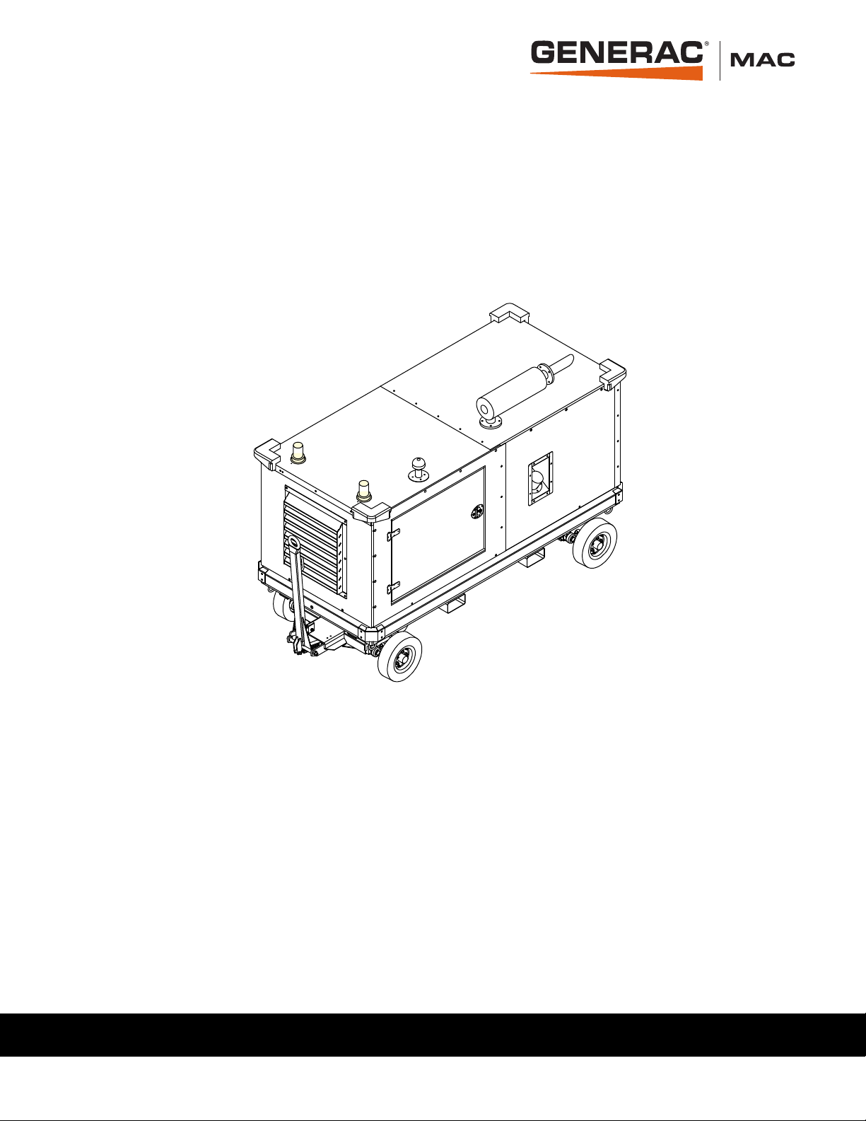
MAC400FHC
004390
Flameless Heat Cart
Owner’s Manual
MODEL NUMBER: _________________________
SERIAL NUMBER: _________________________
DATE PURCHASED:________________________
SAVE THIS MANUAL FOR FUTURE REFERENCE
Page 2

WARNING
CANCER AND REPRODUCTIVE HARM
www.P65Warnings.ca.gov.
(000393a)
ii Owner’s Manual for Flameless Heat Cart
Page 3

Table of Contents
Section 1: Introduction and Safety
Introduction ..................................................................1
Read This Manual Thoroughly ....................................1
Safety Rules .................................................................1
How to Obtain Service .................................................1
General Hazards ...........................................................2
Explosion and Fire Hazards ........................................2
Towing Hazards ...........................................................3
Battery Hazards ............................................................3
Service Safety ..............................................................3
Section 2: General Information
Specifications................................................................5
Internal Component Locations ....................................6
External Component Locations ...................................7
Emissions Information ................................................8
Engine Oil Recommendations ....................................8
Selection of Viscosity ..................................................8
Coolant Recommendations ........................................8
Fuel System ..................................................................8
Hydraulic Oil .................................................................9
Cart Towing Guidelines ...............................................9
Parking Brake Use ......................................................9
Controller ....................................................................10
Monitoring, Diagnostic, and Protective Features .......10
Section 4: Maintenance
Maintenance ...............................................................17
Maintenance Tasks ....................................................17
Daily Walk Around Inspection ...................................17
Draining and Refilling the Oil ..................................... 17
Adding Coolant .......................................................... 18
Maintenance Schedule ..............................................18
Engine Maintenance Schedule................................... 19
Other Maintenance Checks........................................ 20
Battery Inspection ......................................................21
Battery Installation and Replacement ........................ 21
Other Maintenance Checks .......................................22
Short Term Storage ................................................... 22
Return to Service .......................................................22
Section 5: Troubleshooting
General Troubleshooting Guide................................23
Digital Controller Status Messages........................... 26
Section 6: Installation Diagrams
Engine Harness (1 of 3)..............................................27
Engine Harness (2 of 3)..............................................28
Engine Harness (3 of 3)..............................................29
Hydraulic System Schematic.....................................30
Hydraulic Heat System ...............................................31
Section 3: Operation
Theory of Operation ...................................................11
Before Starting Engine ..............................................11
Pre-Start Checklist ....................................................11
Engine Oil Level Check .............................................11
Hydraulic Oil Check ...................................................11
Engine Coolant Check ...............................................11
Ducting Guidelines ....................................................12
Engine and Heater Startup ........................................12
Adjusting Heater Output ...........................................13
AUTO Mode ..............................................................13
MANUAL Mode .........................................................13
Heater and Engine Shutdown ...................................14
Positive Air Shutdown (PAS) ....................................14
Testing the PAS ........................................................15
Resetting the PAS .....................................................15
Owner’s Manual for Flameless Heat Cart iii
Page 4

This page intentionally left blank.
iv Owner’s Manual for Flameless Heat Cart
Page 5
Section 1: Introduction and Safety
(000100a)
WARNING
Consult Manual. Read and understand manual
completely before using product. Failure to
completely understand manual and product
could result in death or serious injury.
(000001)
DANGER
Indicates a hazardous situation which, if not avoided,
will result in death or serious injury.
(000002)
WARNING
Indicates a hazardous situation which, if not avoided,
could result in death or serious injury.
(000003)
CAUTION
Indicates a hazardous situation which, if not avoided,
could result in minor or moderate injury.
Introduction and Safety
Introduction
Thank you for purchasing a Generac Mobile Products,
LLC product. This unit has been designed to provide
high-performance, efficient operation, and years of quality use when maintained properly.
The MAC400FHC flameless heat cart is designed and
built for sustained, reliable heat production in industrial
operating conditions and environments. The
MAC400FHC is built to withstand frequent handling
under these conditions.
The unit has forklift access and chain attach points on
both sides. The fully enclosed design protects the operating components, allowing all-weather storage and operations.
The information in this manual is accurate based on
products produced at the time of publication. The manufacturer reserves the right to make technical updates,
corrections, and product revisions at any time without
notice.
Read This Manual Thoroughly
Throughout this publication, and on tags and decals
affixed to the unit, DANGER, WARNING, CAUTION, and
NOTE blocks are used to alert personnel to special
instructions about a particular operation that may be hazardous if performed incorrectly or carelessly. Observe
them carefully. Alert definitions are as follows:
If any section of the manual is not understood, contact
your nearest Generac Mobile Products (GMP) Authorized Service Dealer (ASD), or contact Generac Mobile
Products Customer Service at 800-926-7968, or visit
http://www.generacmobileproducts.com with any ques-
tions or concerns.
The owner is responsible for proper maintenance and
safe use of the equipment.
SAVE THESE INSTRUCTIONS for future reference. This
manual contains important instructions for the unit that
should be followed during installation, operation, and
maintenance of the heater and batteries. ALWAYS supply
this manual to any individual that will use the unit.
Safety Rules
The manufacturer cannot anticipate every possible circumstance that might involve a hazard. The alerts in this
manual, and on tags and decals affixed to the unit, are
not all-inclusive. If using a procedure, work method, or
operating technique that the manufacturer does not specifically recommend, verify that it is safe for others and
does not render the equipment unsafe.
Owner’s Manual for Flameless Heat Cart 1
NOTE: Notes contain additional information important to
a procedure and will be found within the regular text of
this manual.
These safety alerts cannot eliminate the hazards that
they indicate. Common sense and strict compliance with
the special instructions while performing the action or
service are essential to preventing accidents.
How to Obtain Service
When the unit requires servicing or repairs, contact a
GMP ASD for assistance. Service technicians are factory-trained and are capable of handling all service
needs. Go to https://www.generacmobileproducts.com/
parts-service/find-service for assistance locating a
dealer.
When contacting a GMP ASD about parts and service,
always supply the complete model and serial number of
the unit as given on its data decal located on the unit.
Record the model and serial numbers in the spaces provided on the inside front cover of this manual.
Page 6
Introduction and Safety
Asphyxiation. Running engines produce
carbon monoxide, a colorless, odorless,
poisonous gas. Carbon monoxide, if not
avoided, will result in death or serious injury.
(000103)
DANGER
DANGER
(000239)
Hydraulic Fluid Injection. High-pressure, high-temperature
hydraulic fluid can pierce skin and cause severe burns. Do not
check for leaks with hands. Seek immediate medical attention in case of
accident. Failure to protect body accordingly will result in death or serious
injury.
(000107)
WARNING
Hearing Loss. Hearing protection is
recommended when using this machine.
Failure to wear hearing protection could
result in permanant hearing loss.
(000111)
WARNING
Moving Parts. Keep clothing, hair, and
appendages away from moving parts. Failure
to do so could result in death or serious injury.
(000108)
WARNING
Hot Surfaces. When operating machine, do not
touch hot surfaces. Keep machine away from
combustibles during use. Hot surfaces could
result in severe burns or fire.
(000377)
WARNING
Vision loss. Eye protection is required when
servicing unit. Failure to do so could result in
vision loss or serious injury.
CAUTION
(000229)
Equipment or property damage. Do not block air
intake or restrict proper air flow. Doing so could
result in unsafe operation or damage to unit.
CAUTION
(000240a)
Unit damage. Do not stop engine before heating
unit is cooled. Doing so could result in unit damage.
CAUTION
(000246)
Equipment Damage. The emergency stop switch is
not to be used to power down the unit under normal
operating circumstances. Doing so will result in
equipment damage.
(000105)
DANGER
Explosion and Fire. Fuel and vapors are
extremely flammable and explosive. Add fuel
in a well ventilated area. Keep fire and spark
away. Failure to do so will result in death
or serious injury.
(000143)
DANGER
Explosion and Fire. Fuel and vapors are extremely
flammable and explosive. Store fuel in a well
ventilated area. Keep fire and spark away. Failure
to do so will result in death or serious injury.
(000214)
DANGER
Explosion and Fire. Do not fill fuel tank past full line.
Allow for fuel expansion. Overfilling may cause fuel
to spill onto engine causing fire or explosion, which
will result in death or serious injury.
(000147)
WARNING
Risk of Fire. Unit must be positioned in a
manner that prevents combustible material
accumulation underneath. Failure to do so
could result in death or serious injury.
WARNING
Fire risk. Fuel and vapors are extremely
flammable. Do not operate indoors. Doing so
could result in death, serious injury, or
property or equipment damage.
(000281)
General Hazards
Explosion and Fire Hazards
2 Owner’s Manual for Flameless Heat Cart
Page 7
Towing Hazar ds
WARNING
Explosion and fire risk. Do not smoke near unit.
Keep fire and spark away. Failure to do so could
result in death, serious injury, or property or
equipment damage.
(000282)
WARNING
Crushing hazard. Verify parking brake is properly
secured and unit is on level ground. An unsecured
unit could suddenly roll or move, and could result in
death, serious injury, or equipment damage.
(000352)
WARNING
Property or Equipment Damage. Tighten wheel lug
nuts every 30 days to factory specifications. Failure to
do so could result in death, serious injury, or property
or equipment damage.
(000364)
WARNING
Control loss. Trailer must be securely coupled to the
hitch. An incorrectly coupled trailer could result in loss
of control, death, or serious injury.
(000360)
Personal injury. Do not operate unit during transport.
Doing so could result in death, serious injury, or
property damage.
(000231a)
WARNING
(000137a)
WARNING
Explosion. Batteries emit explosive gases while charging.
Keep fire and spark away. Wear protective gear when
working with batteries. Failure to do so could result in
death or serious injury.
(000162)
WARNING
Explosion. Do not dispose of batteries in a fire. Batteries
are explosive. Electrolyte solution can cause burns and
blindness. If electrolyte contacts skin or eyes, flush with water
and seek immediate medical attention.
(000163a)
WARNING
Risk of burn. Do not open or mutilate batteries.
Batteries contain electrolyte solution which can
cause burns and blindness. If electrolyte contacts
skin or eyes, flush with water and seek immediate
medical attention.
(000130)
WARNING
Accidental Start-up. Disconnect the negative battery
cable, then the positive battery cable when working
on unit. Failure to do so could result in death
or serious injury.
WARNING
Environmental Hazard. Always recycle batteries at an
official recycling center in accordance with all local
laws and regulations. Failure to do so could result in
environmental damage, death or serious injury.
(000228)
Introduction and Safety
Battery Hazards
Always recycle batteries in accordance with local laws
and regulations. Contact your local solid waste collection
site or recycling facility to obtain information on local
recycling processes. For more information on battery
recycling, visit the Battery Council International website
at: http://batterycouncil.org
Service Safety
• DO NOT perform even routine service (oil/filter
changes, cleaning, etc.) unless all electrical components are shut down.
• Replace all missing and hard to read decals.
Decals provide important operating instructions
and warn of dangers and hazards.
• Wear all task-appropriate Personal Protective
Equipment (PPE) when completing maintenance
or service tasks.
Owner’s Manual for Flameless Heat Cart 3
Page 8

Introduction and Safety
This page intentionally left blank.
4 Owner’s Manual for Flameless Heat Cart
Page 9

Section 2: General Information
Specifications
Heater 400,000 BTU/hour (117.2 kW/hour) maximum
Type Flameless
Power Isuzu 4LE2X Tier 4 turbo diesel, 66 HP (49.2 kW)
Operating Speed 2400 rpm
Engine Controls/Display IFM CR0403 / Murphy PV405
General Information
Air Velocity
Battery 950CCA wet cell battery
Static Pressure
Air Outlet 12 in (305 mm)
Electrical 12V
Engine Fuel Diesel (Number 1-D, Number 2-D)
Engine Fuel Capacity 55 gal (208 L)
Engine Oil Capacity 11 qt (10.4 L)
Engine Coolant Capacity 2.5 gal (9.5 L)
HTF Capacity 24 gal (90.8 L)
Engine Fuel Rate (at 100% prime) 3.2 gph (12.1 Lph)
Run Time 18.8 hr
Temperature Rise 180 °F (82 °C)
Pump Hydraulic piston pump
Fan 18.25 in (46.36 cm) diameter backward inclined
3600 CFM (6116 m
9 in H
O (22.8 mm H2O)
2
3
/hour)
Hitch Type Pintle ring
Tire Size 4 in x 8 in (10.2 cm x 20.3 cm)
Lug Nut Torque 100 ft-lbs (135.6 Nm)
Duct Length 25 ft (7.6 m)
Estimated Heater Efficiency 85%
Dimensions 120 in x 54 in x 82 in (3.05 m x 1.37 m x 2.08 m)
Weight 4700 lbs (2131.9 kg) operating weight
Owner’s Manual for Flameless Heat Cart 5
Page 10
General Information
001918
001920
A
B
C
D
E
F
G
H
J
K L
M
N
P
Q
R
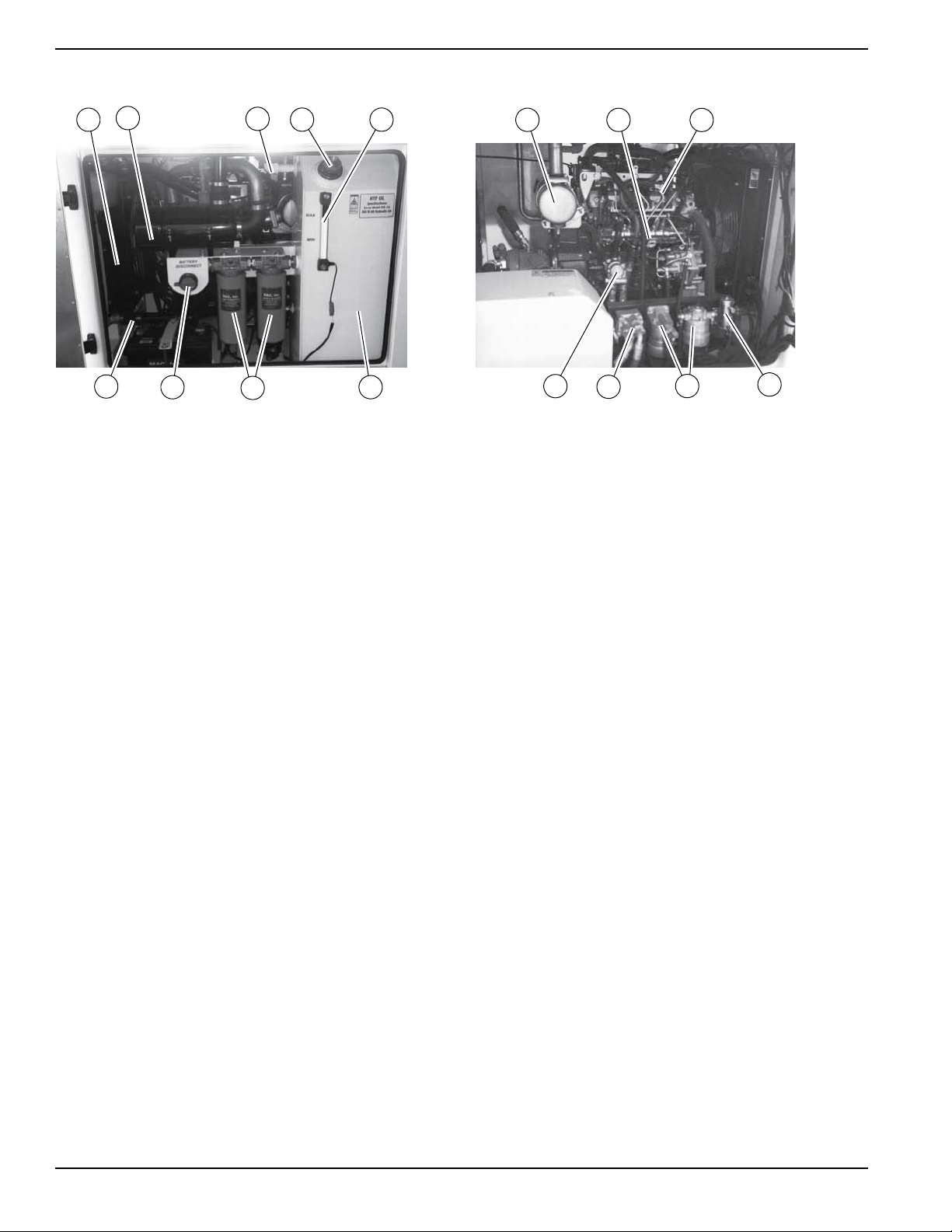
Internal Component Locations
Figure 2-1. Heater Components
A Engine radiator K Diesel oxidation catalyst
B Air filter L Engine oil dipstick
C Hydraulic fluid breather/separator M Diesel injection system
D Hydraulic fluid fill N Fuel pump
E Reservoir fluid-level indicator P Fuel filters
F Hydraulic fluid reservoir Q Engine oil filter
G Hydraulic fluid filters R Engine oil cooler
H Battery disconnect switch
J Fluid drain (oil, fuel, coolant)
6 Owner’s Manual for Flameless Heat Cart
Page 11
External Component Locations
004395
A
C
B
D
E
F
G
H
C
L
M
I
J
K
General Information
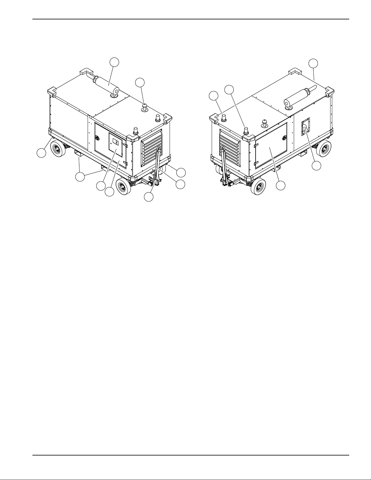
Figure 2-2. External Components
A Muffler I Ducting storage (rear)
B Air intake cap J Diesel fuel fill
C Tie-down rings K Street side engine access
D Tow hitch L Temperature beacon (amber)
E Parking brake lever M Low fuel level beacon (blue)
F Curb side engine access
G Control panel
H Fork lift pockets
Owner’s Manual for Flameless Heat Cart 7
Page 12
General Information
(000149)
DANGER
Risk of poisoning. Do not use mouth to siphon
coolant. Doing so will result in death or serious
injury.
(000168)
DANGER
Explosion and Fire. Fuel and vapors are
extremely flammable and explosive. Keep fire
and spark away. Failure to do so will result
in death or serious injury.
(000204)
DANGER
Explosion and Fire. Do not overfill fuel tank.
Overfilling may cause fuel to leak and ignite
or explode, resulting in death or serious injury.
Emissions Information
See the diesel engine manual for more information.
Engine Oil Recommendations
Grade Type
API CE, CE, CF, CF-4, CH-4, CI-4, CI-4 plus
ACEA A3/B3, A3/B4, A5/B5, E2, E3, D4, E5, E7
JASO DH-1
NOTE: Certain brands/types of oil can be used regardless of specified API or ACEA grade.
Change oil and oil filter at least once every 12 months,
even if the hours of operation are fewer than the otherwise recommended service interval. See the diesel
engine manual for recommended oil types.
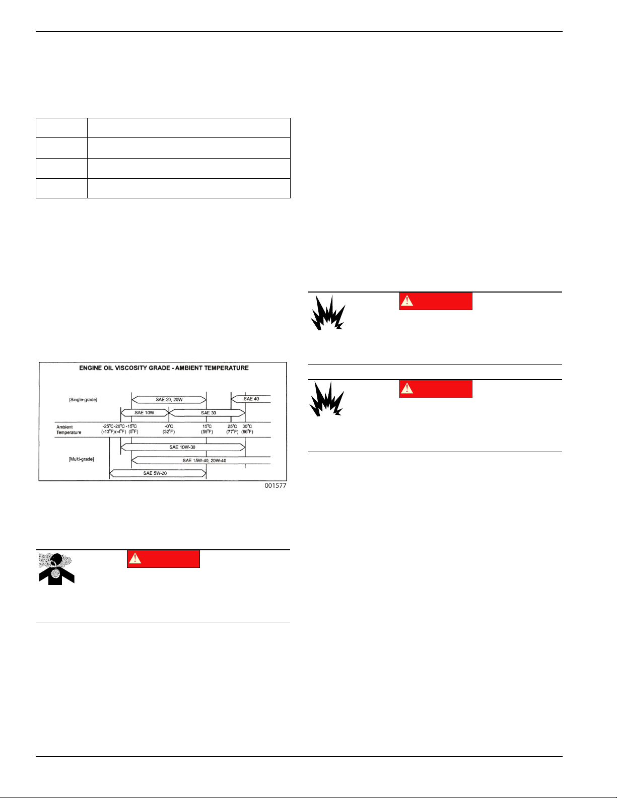
Selection of Viscosity
The chart below shows appropriate oil types according to
ambient temperature.
recommended to eliminate the need for repeated draining and refilling. Follow these antifreeze/water guidelines:
• A 50/50 ethylene glycol base antifreeze/water mix,
which provides protection to -34 °F (-37 °C), is
recommended for use in this engine.
• Never exceed a 60/40 antifreeze/water mix, which
provides protection to approximately -58 °F (-50
°C).
• Coolant must be nitrite free and meet the perfor-
mance standards of ASTM D6210.
NOTE: Recommended coolant is ZEREX™ Nitrate Free
Extended Life Antifreeze/Coolant.
Test coolant yearly, or every 1000 hours, whichever
comes first. See the diesel engine manual for more information.
Fuel System
The engine is designed to use either Number 1-D or
Number 2-D diesel fuel.
Figure 2-3. Engine Oil Viscosity Chart
Coolant Recommendations
• Use Number 2-D diesel fuel whenever possible for
better fuel economy.
• Use Number 1-D or a winterized blend at tempera-
tures below 20 °F (-7 °C) (check with the service
station operator to verify the fuel is properly
blended).
The following are required for diesel fuel:
• Must be free from dust particles.
• Must have adequate viscosity.
• Must have high cetane value.
Use of improper coolants can damage the engine cooling
system. Use demineralized or distilled water for best
results. Hard water causes scale deposits, which reduces
cooling efficiency and raises internal temperatures,
possibly leading to engine damage.
The cooling system should be drained after engine operation in areas where the atmospheric temperature falls
below freezing. The use of antifreeze solution is highly
8 Owner’s Manual for Flameless Heat Cart
• Must have high fluidity at low temperature.
• Must have low or ultra-low sulfur (ULSD) content
EPA requirement; varies by geographic location.
• Must have little residual carbon.
Page 13

Applicable Standard Recommendation
DANGER
(000239)
Hydraulic Fluid Injection. High-pressure, high-temperature
hydraulic fluid can pierce skin and cause severe burns. Do not
check for leaks with hands. Seek immediate medical attention in case of
accident. Failure to protect body accordingly will result in death or serious
injury.
WARNING
Property or Equipment Damage. Tighten wheel lug
nuts every 30 days to factory specifications. Failure to
do so could result in death, serious injury, or property
or equipment damage.
(000364)
WARNING
Control loss. Trailer must be securely coupled to the
hitch. An incorrectly coupled trailer could result in loss
of control, death, or serious injury.
(000360)
WARNING
Crushing hazard. Verify parking brake is properly
secured and unit is on level ground. An unsecured
unit could suddenly roll or move, and could result in
death, serious injury, or equipment damage.
(000352)
CAUTION
(000313)
Pinching and crushing hazard. To avoid
possible injury, keep fingers away from pivot
point when folding or unfolding trailer tongue.
JIS (Japanese Industrial Standard) No. 2
DIN (Deutsche Industrie Normen) DIN 51601
SAE (Society of Automotive
Engineers)
Based on SAE-J-313C
BS (British Standard)
Based on BS/2869-1970
Engine performance will be diminished if fuel other than
what is specified is used. See the engine manual for
more information.
No. 2-D
Class A-1
Hydraulic Oil
General Information
Driving a vehicle with a cart in tow is vastly different than
driving the same vehicle without a cart in tow. Consider
the following:
• It takes longer to get up to speed.
• More room is needed to turn.
• More distance is needed to stop.
• The driver is responsible for keeping the vehicle
and cart in control, and for all damage caused if
control is lost.
Before towing, verify the following:
• Coupling, tires, wheels, and lights are in working
order.
• Wheel lug nuts are tightened to 100 ft-lbs (135.6
Nm).
• The unit is not running.
While towing, make regular stops to verify the following:
• Coupler is secured to the hitch and locked.
• No damage or unusual wear to tire treads or side-
walls.
• Cart and doors are latched and secured.
Type: Exxon Mobil DTE-10 ISO VG 68 hydraulic oil.
Cart Towing Guidelines
NOTE: Do not exceed 15 mph (24 km/h).
The front axle is steered by a tow bar with a pintle ring
hitch. It is equipped with a mechanical parking brake
activated by raising the tow bar to the locked position.
NOTE: See the tow vehicle manual for coupling instructions.
Parking Brake Use
See Figure 2-4. Engage the parking brake by raising the
tow bar to the locked position. The locking lever (A) holds
the tow bar in place. Do not operate the unit without the
parking brake engaged.
Lift the locking lever up and slowly lower the tow bar to
disengage the parking brake.
NOTE: Do not attempt to move the unit with the parking
brake engaged; equipment damage may occur.
Owner’s Manual for Flameless Heat Cart 9
Page 14

General Information
004393
A
001578
A
B
C
D
E
F
G
Figure 2-4. Parking Brake Engaged
Controller
For troubleshooting, see Digital Controller Status Mes-
sages.
NOTE: Contact a GMP ASD to change controller mode
between AUTO or MANUAL, if desired.
Monitoring, Diagnostic, and Protective Features
Mechanical and electrical systems are connected to various sensors that monitor unit status. The controller will
automatically stop the unit and display fault information if
conditions occur outside of predetermined manufacturing
parameters. The controller can also display a variety of
critical alerts, diagnostics, and recommendations. The
controller provides a variety of real-time current operating
condition data. See the engine harness wiring diagrams
for more information.
Figure 2-5. Controller in AUTO Mode
Button Position MANUAL Mode AUTO Mode
A Increase heat
B Increase fan
Increase temp
setting
Decrease
temp setting
C Overview/Analog gauge screen
D Main menu
E Heater on/off
F Next screen
G Popup “Softkeys”
10 Owner’s Manual for Flameless Heat Cart
Page 15

Section 3: Operation
(000108)
WARNING
Hot Surfaces. When operating machine, do not
touch hot surfaces. Keep machine away from
combustibles during use. Hot surfaces could
result in severe burns or fire.
(000135)
CAUTION
Engine damage. Verify proper type and quantity of
engine oil prior to starting engine. Failure to do so
could result in engine damage.
(000154)
WARNING
Risk of burns. Do not open coolant system
until engine has completely cooled. Doing so
could result in serious injury.
Operation
Theory of Operation
The flameless heater generates heat by running pressurized fluid through a restrictive orifice, which drops the
hydraulic pressure and results in heated fluid. A fan then
blows air over the heat exchanger to push heated air out
through the heat ducts.
Before Starting Engine
Pre-Start Checklist
Remove all flammable materials and fire hazards
•
within 5 ft (1.5 m) of the unit.
• Keep unit a minimum of 10 ft (3 m) from structures
or barricades.
• Verify the unit is not leaking fluids: check inside
and outside the unit for leaking fuel, engine oil,
HTF/hydraulic oil, and engine coolant.
• Verify the following are clear of debris and obstruc-
tions:
– Engine air intake
– Engine exhaust stack
– Outlets and fan intakes
• Verify the air duct hose is securely fastened to out-
let duct assembly.
• Check fuel, engine oil, hydraulic fluid, and engine
coolant levels.
• Verify unit is properly secure and level with the
parking brake engaged.
• Inspect the alternator drive belt for tension and
abnormalities.
• Verify battery cable connections are not loose or
corroded.
• Inspect ducting for damage or unusual wear.
Engine Oil Level Check
NOTE: Wait at least 10 minutes before proceeding if the
engine was running.
1. Remove oil dipstick from crankcase and wipe it
clean with a clean, lint free cloth.
2. Insert oil dipstick fully into oil dipstick tube and then
remove slowly.
3. Oil level must be between the FULL and ADD
marks on the oil dipstick.
4. Add oil (if necessary) to adjust the level. After adding or changing the oil, run the engine for one minute before checking the oil level. Wait 10 minutes
to allow the engine to cool and oil to fully drain into
the oil pan.
Typical causes of inaccurate oil level readings:
• Reading the high level of oil dipstick.
• Reading oil dipstick before oil fully drains into oil
pan.
• Inserting and removing oil dipstick too quickly.
• Removing and reading the oil dipstick before fully
seating the oil dipstick into oil dipstick tube.
Hydraulic Oil Check
On the hydraulic fluid reservoir tank is a gauge showing
hydraulic oil level. Verify level is between MIN and MAX.
Engine Coolant Check
Owner’s Manual for Flameless Heat Cart 11
1. Remove radiator fill cap.
2. Check coolant level and degree of fouling. Level
should be approximately 0.39 in (10 mm) below the
radiator core top.
3. Install radiator cap securely.
Page 16

Operation
WARNING
Burn hazard. Do not remove ducting until all air
pressure has been emptied from hose duct.
Failure to do so could result in severe injury.
(000288)
(000108)
WARNING
Hot Surfaces. When operating machine, do not
touch hot surfaces. Keep machine away from
combustibles during use. Hot surfaces could
result in severe burns or fire.
WARNING
Crushing hazard. Verify parking brake is properly
secured and unit is on level ground. An unsecured
unit could suddenly roll or move, and could result in
death, serious injury, or equipment damage.
(000352)
CAUTION
(000291)
Equipment damage. Do not attempt to start or operate
a unit in need of repair or scheduled maintenance.
Doing so could result in serious injury, death, or
equipment failure or damage.
WARNING
CAUTION
(000229)
Equipment or property damage. Do not block air
intake or restrict proper air flow. Doing so could
result in unsafe operation or damage to unit.
CAUTION
(000289)
Equipment damage. Do not use starting aids in the
engine air intake system. Such aids can cause
immediate engine damage.
CAUTION
(000290)
Equipment damage. Do not cover unit during
operation. All ducting ports must remain open
even if not being used. Failure to do so will
result in equipment damage.
001580
CAUTION
(000230)
Equipment Damage. Do not continuously crank
engine for more than ten seconds. Doing so will lead
to overdischarge of batteries and starter seizure.
Ducting Guidelines
• Place ducting in desired configuration before oper-
ating unit.
• Tightly secure ducting ends to the unit and the air
craft.
• Avoid sharp bends or 90° turns in the ducting.
• Use only the necessary length of ducting required;
do not exceed maximum length.
• Verify the ducting is not in a high traffic area, and
will not impede workers or other machinery. Care
should be taken to eliminate the need to step or
climb over ducting.
• DO NOT place ducting over combustible materials.
• DO NOT place ducting over surfaces that may
damage it or reduce performance, such as water,
sharp rocks or glass, electrical wiring, piping, etc.
• DO NOT place or drape anything over ducting,
such as covers, insulation, blankets or cloth, electrical wires, etc.
Engine and Heater Startup
1. Complete the Pre-Start Checklist.
2. Close all access doors.
NOTE: All doors on the unit must be closed when oper-
ating.
3. Raise tow bar to engage parking brake.
4. See Figure 3-1. Turn ignition key to ON. The
screen displays “Engine Preheat”.
Figure 3-1. Engine Preheat
5. See Figure 3-2. Wait approximately five seconds
for fuel pump to build pressure. Turn ignition key to
START when the screen displays “Start Engine”.
12 Owner’s Manual for Flameless Heat Cart
Page 17

Figure 3-2. Start Engine
001584
001585
001581
001586
001578
A
B
6. Attach air ducting to aircraft, avoiding sharp bends
and twists in duct.
Operation
9. See Figure 3-5. When the heater is warm, heat
begins blowing from ducts, the amber strobe light
on top of the unit activates, and the screen displays
“Heater On — Press OFF to stop the heater”.
NOTE: A twisted or bent air duct will cause loss of air
pressure and temperature.
7. See Figure 3-3. The screen displays “Engine
Warming — Please Wait”.
Figure 3-3. Engine Warming
8. See Figure 3-4. Press ON to start the heat
sequence. Engine warming is complete and the
heater automatically begins warming when coolant
temperature reaches 140 °F (60 °C). The screen
displays “Heater is warming up—Please wait”.
Figure 3-5. Heater On
Adjusting Heater Output
Use the up and down arrows to adjust temperature selection to desired outlet temperature. The options are 100 °F
(38 °C), 120 °F (49 °C), 140 °F (60 °C), and 160 °F (71
°C). Monitor regularly and adjust as needed.
AUTO Mode
In AUTO mode, output temperature is manually set, as
follows:
• To increase output temperature, press (+) (Figure
3-6, item A).
• To decrease output temperature, press (-) (Figure
3-6, item B).
Figure 3-6. AUTO Mode
MANUAL Mode
In MANUAL mode, heater output can be set to minimum
fan or maximum fan, as follows:
• For minimum fan, press MIN FAN (Figure 3-7, item
Figure 3-4. Heater Warming
Owner’s Manual for Flameless Heat Cart 13
A). Minimum fan produces the highest temperature
at the lowest air flow.
Page 18

Operation
001579
A
B
C
CAUTION
(000246)
Equipment Damage. The emergency stop switch is
not to be used to power down the unit under normal
operating circumstances. Doing so will result in
equipment damage.
001582
A
CAUTION
(000240a)
Unit damage. Do not stop engine before heating
unit is cooled. Doing so could result in unit damage.
CAUTION
(000246)
Equipment Damage. The emergency stop switch is
not to be used to power down the unit under normal
operating circumstances. Doing so will result in
equipment damage.
• For maximum fan, press MAX FAN (Figure 3-7,
item B). Maximum fan produces a lower temperature at a higher air flow.
Figure 3-7. MANUAL Mode
Heater and Engine Shutdown
001583
Figure 3-9. Cooling Complete
2. Turn ignition key to OFF.
1. Press OFF. Heater stops; blower continues running
and a countdown displays. The screen displays
“Heater is cooling down — Please wait” (Figure 3-
8).
Figure 3-8. Heater Cooling
NOTE: During cool down, the ON button (A) is disabled.
The blower stops when the countdown expires. The display indicates when it is okay to shut off the engine (Fig-
ure 3-9).
3. Disconnect air duct from airplane.
IMPORTANT NOTE: Do not detach air duct until all air
pressure is emptied from the duct.
4. Retract air duct and place in storage area.
5. Turn main battery disconnect to OFF.
Positive Air Shutdown (PAS)
See Figure 3-10. This unit is equipped with a manually
activated positive air shutdown (PAS) on the air intake. If
the atmosphere contains combustible propane or natural
gas, a positive air shutdown can be activated to prevent
these gases from being drawn into the engine and igniting.
The PAS system stops the engine by closing an internal
valve and obstructing intake air. See Figure 3-11. The
PAS is activated by pulling the red T-handle outwards.
The reset knob rotates clockwise to block airflow.
14 Owner’s Manual for Flameless Heat Cart
Page 19

Figure 3-10. Reset Handle in Ready State
004471
004470
Operation
5. Reset the T-handle.
6. Repeat steps in Engine and Heater Startup to
start unit.
Figure 3-11. Emergency Stop T-Handle
Testing the PAS
Test the PAS at least once a month to ensure optimal
valve performance.
Pull the T-handle with the unit completely shut down to
manually test the PAS. This action triggers an actuator,
closing the butterfly valve inside the valve body. An
audible click or series of clicks can be heard when the
actuator engages. Confirm that the valve is closed by
verifying that the reset knob is rotated completely
clockwise. If any resistance is felt, or the valve does not
close, contact Generac Mobile Products Technical
Support.
Resetting the PAS
The emergency PAS system must be reset after each
emergency event according to the steps below:
1. Turn the control power switch to OFF (O).
2. Locate the PAS valve located inside the cabinet of
the unit.
3. See Figure 3-11. Pull T-handle on the PAS valve
outwards until there is an audible “click”.
4. See Figure 3-10. Turn rest knob counter-clockwise
90 degrees until there is an audible “click”.
Owner’s Manual for Flameless Heat Cart 15
Page 20

Operation
This page intentionally left blank.
16 Owner’s Manual for Flameless Heat Cart
Page 21

Section 4: Maintenance
(000139)
WARNING
Risk of burns. Allow engine to cool before
draining oil or coolant. Failure to do so could
result in death or serious injury.
Potential of cancer. Prolonged or repeated contact
with used motor oil has been shown to cause cancer
in laboratory animals. Thoroughly wash exposed
areas with soap and water.
(000127a)
WARNING
004404
A
Maintenance
Maintenance
Regular maintenance will improve performance and
extend engine/equipment life. Generac Mobile Products,
LLC. recommends that all maintenance work be performed by a Generac Mobile Products Authorized Service Dealer (GMP ASD). Regular maintenance,
replacement, or repair of the emissions control devices
and systems may be performed by any repair shop or
person of the owner’s choosing. To obtain emissions control warranty service free of charge, the work must be
performed by a GMP ASD. See the emissions warranty.
Maintenance Tasks
Daily checks must be performed when unit is operated
continuously for extended periods of time. Daily checks
and routine monthly checks can be performed by an
authorized operator.
NOTE: Normal maintenance, service, and replacement
of parts are the responsibility of the owner and are not
considered defects in materials or workmanship within
the terms of the warranty. It is strongly recommended
that equipment be periodically checked by a GMP ASD.
Draining and Refilling the Oil
Proceed as follows to drain the oil:
1. See Figure 4-1. Place a suitable container under
unit. A drain hose (A) is attached to the drain port
and routed through the bottom of the enclosure to
drain the oil.
Daily Walk Around Inspection
Check for conditions that could hinder performance or
safety, such as (but not limited to) oil, coolant, and fuel
leakage, blocked vents, loose or missing hardware, and
improper electrical connections. Check for foreign matter
blocking the vents and on top of unit.
• Inspect outer cover for significant damage beyond
scuffs and small nicks.
• Inspect for wire abrasion.
• Inspect the fan belt for cracking, fraying, and
stretching. Verify the belt is properly seated in the
pulley grooves.
• Check coolant.
• Check electrical connectors, battery, and ground
points. Look for loose or missing hardware.
• Check all flexible rubber hoses for deterioration.
• Check hydraulic hoses for signs of wear.
• Verify hoses are not crushed, bent, or twisted.
• Verify there are no cracks or corrosion.
• Inspect ducting for damage or unusual wear.
Figure 4-1. Oil Drain Hose
2. Remove plug from oil drain/manifold.
3. Open drain valve. Drain oil.
4. See engine manual for oil filter information.
5. Close drain valve.
6. Replace plug in drain port on sub base.
7. Dispose of waste oil in accordance with local,
state, or national codes or regulations.
8. See Figure 4-2. Remove filler cap (B) on either the
rocker arm cover or on the side of the engine.
Owner’s Manual for Flameless Heat Cart 17
Page 22

Maintenance
004704
B
(000149)
DANGER
Risk of poisoning. Do not use mouth to siphon
coolant. Doing so will result in death or serious
injury.
(000154)
WARNING
Risk of burns. Do not open coolant system
until engine has completely cooled. Doing so
could result in serious injury.
(000165a)
CAUTION
Risk of overheating. Do not use any chromate base
rust inhibitor with propylene glycol base antifreeze,
boosters, or additives. Doing so will cause overheating
and possible equipment damage.
Figure 4-2. Oil Fill Cap Locations
If coolant level is below the filler neck, coolant must be
added. (See Coolant Recommendations.) Proceed as
follows to add coolant:
1. Verify engine is stopped and cooled.
2. Remove radiator cap.
3. Fill radiator slowly with coolant until it comes up to
filler neck.
4. Operate engine for approximately five minutes at a
low idle speed to purge the air in the coolant circuit.
NOTE: Coolant level will drop.
5. Stop the engine and replenish with coolant once
cooled.
9. Fill oil pan to specified level.
10. Replace filler cap.
NOTE: Do not overtighten filler cap. Overtightening may
damage filler cap.
11. Start and run the engine for five minutes. Verify
there are no leaks.
12. Stop the engine and let cool for approximately 10
minutes. Verify the oil level is correct. (See Drain-
ing and Refilling the Oil.) Repeat steps 8–10 until
oil is properly filled.
NOTE: Do not overfill oil pan. Overfilling may result in
white exhaust smoke, sudden engine overspeed, or
engine damage.
Adding Coolant
Maintenance Schedule
Periodic inspection, service, and maintenance of this unit
is critical to ensuring reliable operation. The following is
the manufacturer’s recommended maintenance schedule. The maintenance items need to be performed more
frequently if the unit is used in severe applications (such
as very high or very low ambient conditions or extremely
dirty or dusty environments). Use the unit hour meter or
calendar time, whichever occurs first, from the previous
maintenance interval to determine the next required
maintenance interval.
NOTE: Some checks are based on hours of operation.
Follow all applicable safety alerts in this manual or the
engine service manual before performing any maintenance checks or service.
This maintenance schedule reflects the minimum tasks
needed to verify the unit remains operational. Some of
the tasks can be performed by an authorized operator,
and others must be performed by a GMP ASD.
NOTE: An authorized operator is one who has been
trained by a GMP ASD in proper operation and inspection of this unit.
18 Owner’s Manual for Flameless Heat Cart
Page 23

Maintenance
Engine Maintenance Schedule
To protect the warranty status of the engine, engine maintenance and repairs should be performed by a GMP ASD. For
more information on the checks and maintenance described below, see the engine manual.
• Check engine oil, coolant, hydraulic oil, and engine fuel levels.
• Check radiator filler cap fitting condition.
• Inspect alternator drive belt tension and replace if necessary.
• Inspect fan belt tension.
Daily
• Inspect preheating condition.
• Check engine starting condition.
• Check exhaust smoke condition.
• Inspect hoses and connections.
• Inspect exhaust system for wear and cracking.
Every Six Months
Every 12 Months
At 50 Operation Hours
(Break In)
At 250 Operation Hours
At 500 Operation Hours
At 750 Operation Hours
• Inspect wheel bearings.
• Replace coolant.
• Change engine oil and oil filter.
• Change engine fuel filters.
• Replace fuel filter element.
• Clean water sedimenter element.
• Clean electromagnetic pump filter.
• Change engine oil and oil filter element.
• Inspect engine accessory drive belts.
• Inspect fuel supply system.
• Change engine fuel filters.
• Inspect alternator drive belt tension, and replace if necessary.
• Inspect injection nozzle (*).
• Change fuel filter element.
• Clean water sedimenter element.
• Clean electromagnetic pump filter.
• Replace fuel filter element.
• Clean water sedimenter element.
• Clean electromagnetic pump filter.
• Inspect fan belt for wear. Inspect for hard turning or unusual sounds.
• Inspect fan belt pulleys and bearings.
Owner’s Manual for Flameless Heat Cart 19
Page 24

Maintenance
At 1000 Operation Hours
At 1250 Operation Hours
At 1500 Operation Hours
• Change engine oil and oil filter element.
• Inspect engine accessory drive belts.
• Inspect fuel supply system.
• Clean cooling system circuit.
• Inspect and clean the starter and alternator (*).
• Inspect valve clearance (*).
• Inspect injection nozzle (*).
• Change fuel filter element.
• Clean water sedimenter element.
• Clean electromagnetic pump filter.
• Replace fuel filter element.
• Clean water sedimenter element.
• Clean electromagnetic pump filter.
• Change engine oil and oil filter element.
• Inspect engine accessory drive belts.
• Inspect fuel supply system.
• Clean positive crankcase ventilation valve.
• Inspect injection nozzle (*).
• Change fuel filter element.
• Clean water sedimenter element.
• Clean electromagnetic pump filter.
After 1500 Operation Hours
(*) = When servicing these items, consult the equipment supplier.
NOTE: All service and maintenance or repairs are recommended to be completed by a GMP ASD to maintain the
warranty status of a unit. You cannot be denied emissions warranty coverage solely based on failure to complete
recommended service maintenance.
All hours-based checks and maintenance should now be performed every 250
hours.
Other Maintenance Checks
Every 500 Hours
Every 1000 Hours
• Change air filter.
• Change hydraulic oil.
• Change hydraulic pump filter.
• Change hydraulic breather/separator.
Annually
• Carbon monoxide (CO) test at outlet air duct by trained service technician.
• Inspect blower/fan hardware for condition and tightness.
20 Owner’s Manual for Flameless Heat Cart
Page 25

Maintenance
(000137a)
WARNING
Explosion. Batteries emit explosive gases while charging.
Keep fire and spark away. Wear protective gear when
working with batteries. Failure to do so could result in
death or serious injury.
(000162)
WARNING
Explosion. Do not dispose of batteries in a fire. Batteries
are explosive. Electrolyte solution can cause burns and
blindness. If electrolyte contacts skin or eyes, flush with water
and seek immediate medical attention.
(000163a)
WARNING
Risk of burn. Do not open or mutilate batteries.
Batteries contain electrolyte solution which can
cause burns and blindness. If electrolyte contacts
skin or eyes, flush with water and seek immediate
medical attention.
(000130)
WARNING
Accidental Start-up. Disconnect the negative battery
cable, then the positive battery cable when working
on unit. Failure to do so could result in death
or serious injury.
(000181)
WARNING
Vision Loss. Eye protection is required to avoid
spray from spark plug hole when cranking engine.
Failure to do so could result in vision loss.
WARNING
Environmental Hazard. Always recycle batteries at an
official recycling center in accordance with all local
laws and regulations. Failure to do so could result in
environmental damage, death or serious injury.
(000228)
(000167a)
CAUTION
Equipment damage. Do not make battery
connections in reverse. Doing so will result
in equipment damage.
Battery Inspection
Once every six months, a GMP ASD should inspect the
battery system. At this time, the battery condition and
state of charge should be checked using a load test
battery. The battery should be recharged or replaced as
required.
Battery service must be performed or supervised by
personnel knowledgeable of batteries and the required
precautions. Keep unauthorized personnel away.
Observe the following precautions when working on
batteries:
• Remove watches, rings, or other metal objects.
• Use tools with insulated handles.
• Wear rubber gloves and boots.
• Do not lay tools or metal parts on top of battery.
• Disconnect charging source prior to connecting or
disconnecting battery terminals.
NOTE: Wash spilled electrolyte down with an acid neutralizing agent. A common practice is to use a solution of
1 lb (454 g) bicarbonate of soda (baking soda) to 1 gal
(3.8 L) of water. Add bicarbonate of soda solution until
the evidence of reaction (foaming) has ceased. Flush the
resulting liquid with water.
Always recycle batteries in accordance with local laws
and regulations. Contact your local solid waste collection
site or recycling facility to obtain information on local
recycling processes. For more information on battery
recycling, visit the Battery Council International website
at: http://batterycouncil.org
An authorized operator should inspect the engine battery
monthly. At this time, the battery fluid level should be
checked using a load tester, and distilled water added if
needed. Battery cables and connections should also be
inspected for cleanliness and corrosion.
Owner’s Manual for Flameless Heat Cart 21
NOTE: Discharge state electricity before touching battery by first touching a grounded metal surface.
Battery Installation and Replacement
When required, the battery must be replaced with one of
equivalent size, voltage, and CCA (cold crank amp
capacity). Minimum CCA for this unit is 950. Contact a
GMP ASD for correct battery size. A new battery must be
filled with the proper electrolyte and be fully charge
before installing.
Battery cables are connect to the unit at the factory.
Connect cables to battery posts as follows:
NOTE: Turn the battery disconnect to OFF before
changing the battery.
1. Connect red battery cable from starter contactor to
positive (POS or +) battery post.
2. Connect black battery cable to negative (NEG or -)
battery post.
3. See Engine and Heater Startup.
Page 26

Maintenance
CAUTION
(000291)
Equipment damage. Do not attempt to start or operate
a unit in need of repair or scheduled maintenance.
Doing so could result in serious injury, death, or
equipment failure or damage.
WARNING
Other Maintenance Checks
The following inspections should be performed by an
authorized service technician, or a properly trained
authorized operator. These maintenance items require a
high level of experience and skill to evaluate and correct.
• Inspect exhaust pipe sleeve.
Short Term Storage
When the unit will not be in use for three or more months,
follow the guidelines below to properly store the unit:
• Perform all necessary maintenance or repairs
based on the Maintenance Schedule. If neces-
sary maintenance is upcoming, perform the maintenance action before storing.
• Fill the fuel tank to FULL.
• Fill coolant to FULL. Do not drain.
• Remove all dirt and debris from inside and outside
the enclosure.
• Lock the unit to prevent any unauthorized opera-
tion.
• Store in a safe location — do not position near or
on top of any combustible materials; observe any
local, state, or national codes or regulations. Store
in a low moisture, low dust area.
• Disconnect the negative cable from the battery.
Return to Service
Follow the guidelines below for engines and units that
have not been operated for three to six months:
• Conduct a thorough inspection of the unit before
starting the engine.
• Verify the maintenance schedule is up to date.
• Check all fluids for signs of fouling or degradation.
• After starting the engine, let it warm up for more
than 10 minutes at idle.
NOTE: Do not start or operate a unit in need of repair or
maintenance. Perform all maintenance tasks and repairs
before starting. Contact a GMP ASD if there is any doubt
as to the unit’s usability.
22 Owner’s Manual for Flameless Heat Cart
Page 27

Section 5: Troubleshooting
General Troubleshooting Guide
Problem Cause Solution
Troubleshooting
Engine cranks but will
not start
Engine will not crank
(electric start)
Engine starts but stops
shortly thereafter
Engine running is
unstable
No fuel.
Insufficient oil level. Replenish oil to full.
PAS is ON. Turn PAS to OFF. See Resetting the PAS.
Air in fuel system. Purge air from fuel system.
Clogged fuel filter. Remove water and change element.
Gelled fuel.
Injection pump failure.
Electromagnetic type fuel pump failure.
Engine control system failure.
LCD panel shows engine failure.
Clogged strainer.
Pre-heating device failure.
Restricted air flow. Check/replace air filter.
Discharged battery.
Battery terminal is disconnected, loose, or
corroded.
Starter ground terminal is disconnected,
loose, or corroded.
Excessive engine oil viscosity.
Starter or electrical system failure.
Engine seized.
Low idle.
Clogged fuel filter. Remove water and change element.
Clogged pre-fuel filter.
Clogged air cleaner.
Engine control system failure.
Injection pump failure.
Clogged strainer.
Electromagnetic type fuel pump failure.
Fuel system failure.
Water or air in fuel system. Purge air or remove water.
Engine control system failure. Contact a GMP ASD.
Verify there is no fuel leakage and
replenish.
Warm fuel pipes with hot water or wait until
ambient temperature rises.
Contact a GMP ASD.
Replace battery. See Battery Installation
and Replacement.
Replace corroded part(s) and tighten
securely.
Change with oil of correct viscosity. See
Draining and Refilling the Oil.
Contact a GMP ASD.
Adjust by idling control equipment on the
unit. If adjustment is not possible, contact a
GMP ASD.
Clean or change element.
Contact a GMP ASD.
Owner’s Manual for Flameless Heat Cart 23
Page 28

Troubleshooting
Problem Cause Solution
Exhaust smoke is white
Exhaust smoke is black
Engine overheats
Oil pressure does not
rise
Engine has no power
Insufficient warm-up time. Conduct warm-up operation.
Excessive engine oil.
Engine control system failure.
Injection pump failure.
Fuel system failure.
Excessive idling (more than two hours).
Excessive speed.
Clogged air cleaner. Clean or change element.
Injection pump failure.
Clogged intercooler.
Fuel system failure.
Clogged exhaust system.
No coolant. Add coolant. See Adding Coolant.
Front of radiator is clogged with dust. Clean with soft brush.
Subtank cap is not tightened. Tighten or replace sub tank cap.
Fouled coolant.
Oil in coolant. Contact a GMP ASD.
Thermostat failure. Change thermostat.
Incorrect engine oil viscosity.
Insufficient engine oil.
Engine failure.
Meter, lamp, or switch failure.
Clogged air cleaner.
Clogged pre-fuel filter.
Clogged fuel filter. Remove water and change element.
Clogged strainer.
Engine control system failure.
Engine failure.
Clogged exhaust system.
Fuel system failure.
Incorrect fuel type.
Electromagnetic type fuel pump failure.
Correct oil level. See Draining and Refill-
ing the Oil.
Contact a GMP ASD.
• Verify engine rpm.
• Check AVR adjustment.
Contact a GMP ASD.
Clean inside of radiator and change
coolant.
Change with oil of correct viscosity. See
Draining and Refilling the Oil.
Replenish engine oil. See Draining and
Refilling the Oil.
Contact a GMP ASD.
Clean element.
Contact a GMP ASD.
24 Owner’s Manual for Flameless Heat Cart
Page 29

Problem Cause Solution
Overheat/shutdown
condition
(Check controller for
engine fault shutdown
code)
No/low heat condition
Troubleshooting
Access doors are open. Close all access doors.
Air outlets are closed.
Front radiator or rear oil cooler are full of
debris.
Engine rpm is set too high for ambient
temperature.
Faulty temperature sensor. Check air outlet sensor operation.
Blower fan operating incorrectly.
Incorrect heater setting (target temperature too low).
Access doors are open. Close all access doors.
Open the air outlets and verify there are no
obstructions or tight bends in the ducting.
Clean the unit.
Lower the engine rpm.
Remove ducting; check blower fan operation.
Adjust heater output. See Adjusting
Heater Output.
• Check level on tank sight glass, adjust
as needed.
Insufficient HTF/hydraulic oil level.
• Inspect HTF hoses for leaks or loose
fittings.
• Check fluid for foaming.
Clogged HTF/hydraulic oil filters.
Excessive ducting for ambient conditions.
HTF pump drive sheared. Contact a GMP ASD.
Controller sensor fault. Check sensor related to fault.
Check restriction gauges/replace HTF
filters.
Move unit closer to heat recipient if
possible.
Owner’s Manual for Flameless Heat Cart 25
Page 30

Troubleshooting
Digital Controller Status Messages
Message Cause
Engine Warming — Please Wait Engine coolant temperature < 140 °F (38 °C).
Engine Preheat Wait approximately 10 seconds after heater powers up.
Engine rpm < 500
Engine is not ready — Check rpm, Fuel Level or Wait to
Start
Low Fuel Warning
Fuel level < 10%
Wait to Start signal
Fuel level < 20%
• Fuel level notification appears on screen
• Low Fuel Level beacon turns on
Fuel level ≤ 16%
• Fuel level notification appears on screen
• Heat/fan load reduced to 50%
Fuel level ≤ 12%
• Fuel level notification appears on screen
• Open heat circuit and close scroll fan circuit
• Drop engine to idle
Fuel level ≤ 8%
• Fuel level notification appears on screen
• Engine shuts down
Check heater settings or connections, then press Reset
on the Machine Overview
Heater is cooling down — Please wait
Engine is going to shutdown Fuel level ≤ 8%
Engine fault shutdown
Heater shutdown due to temperature; pressure or level
out of range
IFM controller detected a short or break in a sender.
IFM controller detects heater is in cool down. ON button
disabled.
Low engine oil pressure
High engine coolant temperature
Engine overspeed
High hydraulic temperature
Low hydraulic pressure
Low hydraulic level
26 Owner’s Manual for Flameless Heat Cart
Page 31

Section 6: Installation Diagrams
Engine Harness (1 of 3)
Installation Diagrams
Owner’s Manual for Flameless Heat Cart 27
Page 32

Installation Diagrams
Engine Harness (2 of 3)
28 Owner’s Manual for Flameless Heat Cart
Page 33

Engine Harness (3 of 3)
Installation Diagrams
Owner’s Manual for Flameless Heat Cart 29
Page 34

Installation Diagrams
M1
H1
H1
H1
H1
H1
H1
M1
P1
H1
V1
V1
Large Hydraulic
Exchanger
Small Hydraulic
Exchanger
Hydraulic Oil Tank
Fan
Pressure
Regulating
3-Way Valve
Start-up Bypass
3-Way Valve
Filters
Hydraulic System Schematic
30 Owner’s Manual for Flameless Heat Cart
Page 35

Hydraulic Heat System
ENGINE RADIATOR
C60 HYD
EXCHANGER
LARGE EXHAUST
EXCHANGER
Installation Diagrams
Owner’s Manual for Flameless Heat Cart 31
Page 36

Installation Diagrams
This page intentionally left blank.
32 Owner’s Manual for Flameless Heat Cart
Page 37

Installation Diagrams
This page intentionally left blank.
Owner’s Manual for Flameless Heat Cart 33
Page 38

Installation Diagrams
This page intentionally left blank.
34 Owner’s Manual for Flameless Heat Cart
Page 39

Page 40

Part No. 10000012492 Rev. B 05/16/2018
©2018 Generac Mobile Products, LLC
All rights reserved.
Specifications are subject to change without notice.
No reproduction allowed in any form without prior written
consent from Generac Mobile Products, LLC.
Generac Mobile Products, LLC
215 Power Drive, Berlin, WI 54923
GeneracMobileProducts.com │800-926-9768 │920-361-4442
 Loading...