

Page 1

iQ2000 Portable Generator
000853
(000209b)
WARNING
Loss of life. This product is not intended to
be used in a critical life support application.
Failure to adhere to this warning could result
in death or serious injury.
Owner’s Manual
MODEL:________________________
SERIAL:________________________
DATE PURCHASED:______________
Register your Generac product at:
WWW.GENERAC.COM
1-888-GENERAC
(1-888-436-3722)
SAVE THIS MANUAL FOR FUTURE REFERENCE
Page 2

Table of Contents
(000393)
WARNING
Operating, servicing and maintaining this
equipment can expose you to chemicals
including engine exhaust, carbon monoxide,
phthalates, and lead, which are known to the
State of California to cause cancer and birth
defects or other reproductive harm. To
minimize exposure, avoid breathing exhaust,
do not idle the engine except as necessary,
service your equipment in a well-ventilated
area and wear gloves or wash your hands
frequently when servicing your equipment.
For more information go to
www.P65Warnings.ca.gov.
Section 1 Introduction and Safety 1
Introduction ..................................... 1
Safety Rules .................................... 1
Safety Symbols and Meanings ........ 1
Exhaust and Location Hazards ....... 2
Electrical Hazards ...........................3
Fire Hazards .................................... 3
Standards Index .............................. 3
Section 2 General Information and
Setup .............................................. 4
Know Your Generator ..................... 5
Emissions ........................................ 5
Connection Plugs ............................ 6
PowerDial ........................................ 6
PowerBar ........................................ 6
Economy Switch .............................. 6
Generator Status Lights ..................6
Run Time Display ............................ 6
Fuel Sensor and Fuel Gauge .......... 7
Remove Contents from Carton ....... 7
Add Engine Oil ................................7
Fuel ................................................. 8
Section 3 Operation .......................9
Operation and Use Questions .........9
Before Starting Engine ....................9
Prepare Generator for Use ..............9
Grounding the Generator When Used
as a Portable ...................................9
Know Generator Limits ....................9
Transporting/Tipping of the Unit ....10
Starting Pull Start Engines .............10
Restarting Hot Engines ..................11
Low Oil Level Shutdown System ...11
Parallel Operation ..........................11
Parallel Reset Procedure ...............12
Section 4 Maintenance and
Troubleshooting ..........................13
Maintenance ..................................13
Maintenance Schedule ..................13
Preventive Maintenance ................13
Engine Maintenance ......................13
Storage ..........................................16
Troubleshooting .............................17
Page 3

Section 1 Introduction and Safety
(000100a)
WARNING
Consult Manual. Read and understand manual
completely before using product. Failure to
completely understand manual and product
could result in death or serious injury.
(000001)
DANGER
Indicates a hazardous situation which, if not avoided,
will result in death or serious injury.
(000002)
WARNING
Indicates a hazardous situation which, if not avoided,
could result in death or serious injury.
(000003)
CAUTION
Indicates a hazardous situation which, if not avoided,
could result in minor or moderate injury.
DANGER
Using a generator indoors CAN KILL YOU IN MINUTES.
Generator exhaust contains carbon monoxide. This is
a poison you cannot see or smell.
NEVER use inside a home
or garage, EVEN IF doors
and windows are open.
Only use OUTSIDE and
far away from windows,
doors, and vents.
000657
Introduction
Thank you for purchasing a Generac Power
Systems Inc. product. This unit has been
designed to provide high-performance, efficient operation, and years of use when maintained properly.
If any section of the manual is not understood,
contact your nearest Independent Authorized
Service Dealer (IASD), or contact Generac
Customer Service at 1-888-GENERAC (1888-436-3722), or www.generac.com with any
questions or concerns.
The owner is responsible for proper maintenance and safe use of the equipment. Before
operating, servicing or storing this generator:
• Study all warnings in this manual and on
the product carefully.
• Become familiar with this manual and the
unit before use.
• Refer to Introduction and Safety for instructions on final assembly procedures. Follow
the instructions completely.
Save these instructions for future reference.
ALWAYS supply this manual to any individual
that will use this machine.
The information in this manual is accurate
based on products produced at the time of
publication. The manufacturer reserves the
right to make technical updates, corrections,
and product revisions at any time without
notice.
NOTE: Notes contain additional information
important to a procedure and will be found
within the regular text of this manual.
These safety warnings cannot eliminate the
hazards that they indicate. Common sense
and strict compliance with the special instructions while performing the action or service
are essential to preventing accidents.
Safety Symbols and Meanings
Safety Rules
The manufacturer cannot anticipate every
possible circumstance that might involve a
hazard. The warnings in this manual, and on
tags and decals affixed to the unit are, therefore, not all inclusive. If using a procedure,
work method or operating technique that the
manufacturer does not specifically recommend, verify that it is safe for others. Also
make sure the procedure, work method or
operating technique utilized does not render
the equipment unsafe.
Throughout this publication, and on tags and
decals affixed to the generator, DANGER,
WARNING, CAUTION and NOTE blocks are
used to alert personnel to special instructions
about a particular operation that may be hazardous if performed incorrectly or carelessly.
Observe them carefully. Their definitions are
as follows:
Owner’s Manual for Portable Generator 1
Asphyxiation. Running engines produce carbon
DANGER
monoxide, a colorless, odorless, poisonous gas.
Carbon monoxide, if not avoided,
will result in death or serious injury.
• If you start to feel sick, dizzy, or weak after
the generator has been running, move to
fresh air IMMEDIATELY. See a doctor, as
you could have carbon monoxide poisoning.
(000103)
Page 4

(000179b)
DANGER
Asphyxiation. The exhaust system must be properly
maintained. Do not alter or modify the exhaust system
as to render it unsafe or make it noncompliant with
local codes and/or standards. Failure to do so will
result in death or serious injury.
DANGER
(000116)
DANGER
Electrocution. Turn utility and emergency
power supplies to OFF before connecting power
source and load lines. Failure to do so will result
in death or serious injury.
(000146)
WARNING
Equipment and property damage. Do not alter
construction of, installation, or block ventilation for
generator. Failure to do so could result in unsafe
operation or damage to the generator.
(000178a)
Asphyxiation. Always use a battery operated carbon
monoxide alarm indoors and installed according to
the manufacturer’s instructions. Failure to do so
could result in death or serious injury.
WARNING
(000250)
WARNING
Equipment and property damage. Do not operate unit on
uneven surfaces, or areas of excessive moisture, dirt, dust
or corrosive vapors. Doing so could result in death, serious
injury, property and equipment damage.
(000111)
WARNING
Moving Parts. Keep clothing, hair, and appendages
away from moving parts. Failure to do so could
result in death or serious injury.
(000142a)
Personal injury. Do not insert any object through the
air cooling slots. Generator can start at any time and
could result in death, serious injury, and unit damage.
WARNING
Risk of injury. Do not operate or service this machine
if not fully alert. Fatigue can impair the ability to service
this equipment and could result in death or serious
injury.
(000215)
(000103)
DANGER
Asphyxiation. Running engines produce carbon
monoxide, a colorless, odorless, poisonous gas.
Carbon monoxide, if not avoided,
will result in death or serious injury.
Asphyxiation. The exhaust system must be properly
as to render it unsafe or make it noncompliant with
local codes and/or standards. Failure to do so will
result in death or serious injury.
(000178a)
Asphyxiation. Always use a battery operated carbon
monoxide alarm indoors and installed according to
the manufacturer’s instructions. Failure to do so
could result in death or serious injury.
WARNING
Electrocution. Water contact with a power source,
if not avoided, will result in death or serious injury.
(000104)
Injury and equipment damage. Do not use generator
as a step. Doing so could result in falling, damaged
parts, unsafe equipment operation, and could result
in death or serious injury.
• For safety reasons, it is recommended that
the maintenance of this equipment be performed by an IASD. Inspect the generator
regularly, and contact the nearest IASD for
parts needing repair or replacement.
• Point muffler exhaust away from people
and occupied buildings.
• Minimum generator placement distance of
five feet from windows, doors, or openings
in walls with engine exhaust directed away
from occupied buildings and if possible
downwind.
(000216)
Exhaust and Location Hazards
DANGER
maintained. Do not alter or modify the exhaust system
(000179b)
WARNING
Hot Surfaces. When operting machine, do not
touch hot surfaces. Keep machine away from
combustables during use. Hot surfaces
could result in severe burns or fire.
WARNING
2 Owner’s Manual for Portable Generator
WARNING
(000108)
Equipment and property damage. Do not alter
WARNING
construction of, installation, or block ventilation for
generator. Failure to do so could result in unsafe
operation or damage to the generator.
• If you start to feel sick, dizzy, or weak after
the generator has been running, move to
fresh air IMMEDIATELY. See a doctor, as
you could have carbon monoxide poisoning.
(000146)
Page 5

Electrical Hazards
(000144)
DANGER
Electrocution. Contact with bare wires,
terminals, and connections while generator
is running will result in death or serious injury.
(000104)
DANGER
Electrocution. Water contact with a power source,
if not avoided, will result in death or serious injury.
(000145)
DANGER
Electrocution. In the event of electrical accident,
immediately shut power OFF. Use non-conductive
implements to free victim from live conductor. Apply
first aid and get medical help. Failure to do so will
result in death or serious injury.
(000105)
DANGER
Explosion and Fire. Fuel and vapors are extremely
flammable and explosive. Add fuel in a well
ventilated area. Keep fire and spark away. Failure to
do so will result in death or serious injury.
(000199)
DANGER
Explosion and Fire. LP vapors are extremely ammable
and explosive. Do not use or store LP cylinder in a
building, garage, or enclosed area except as authorized
by NFPA 58 or B149.2 (Canada). Failure to do so will
result in death or serious injury.
(000166b)
Explosion and Fire. Do not overfill fuel tank. Fill to
1/2 inch from top of tank to allow for fuel expansion.
Overfilling may cause fuel to spill onto engine causing
fire or explosion, which will result in death or
serious injury.
(000174)
DANGER
Risk of fire. Allow fuel spills to completely dry
before starting engine. Failure to do so will
result in death or serious injury.
(000142a)
Personal injury. Do not insert any object through the
air cooling slots. Generator can start at any time and
could result in death, serious injury, and unit damage.
• The National Electric Code (NEC) requires
the frame and external electrically conductive parts of the generator be properly connected to an approved earth ground. Local
electrical codes may also require proper
grounding of the generator. Consult with a
local electrician for grounding requirements
in the area.
• Use a ground fault circuit interrupter in any
damp or highly conductive area (such as
metal decking or steel work).
• Once generator has been started outside,
connect electrical loads to extension
cord(s) inside.
Fire Hazards
WARNING
• Do not operate the generator if connected
electrical devices overheat, if electrical output is lost, if engine or generator sparks or if
flames or smoke are observed while unit is
running.
• Keep a fire extinguisher near the generator
at all times.
Standards Index
1. National Fire Protection Association
(NFPA) 70: The NATIONAL ELECTRIC
CODE (NEC) available from www.nfpa.org
2. National Fire Protection Association
(NFPA) 5000: BUILDING CONSTRUCTION AND SAFETY CODE available from
www.nfpa.org
3. International Building Code available from
www.iccsafe.org
4. Agricultural Wiring Handbook available
from www.rerc.org, Rural Electricity
Resource Council P.O. Box 309 Wilmington, OH 45177-0309
5. ASAE EP-364.2 Installation and Mainte-
nance of Farm Standby Electric Power
available from www.asabe.org, American
Society of Agricultural & Biological Engineers 2950 Niles Road, St. Joseph, MI
49085
6. CSA C22.2 100-14 Electric motors and
generators for installation and use, in
accordance with the Rules of the Canadian Electrical Code
7. ANSI/PGMA G300 Safety and Perfor-
mance of Portable Generators. Portable
Generator Manufacturer’s Association,
www.pgmaonline.com
This list is not all inclusive. Check with the
Authority Having Jurisdiction (AHJ) for any
local codes or standards which may be applicable to your jurisdiction.
DANGER
Owner’s Manual for Portable Generator 3
Page 6

Section 2 General Information and Setup
000581
17
14
15
12
18
16
13
20
7
10
3
1
2
8
6
9
54
11
000662
19
000662
Figure 2-1. Features and Controls
TABLE 1. Generator Components
1 Parallel Ready 120 Volts AC Duplex
Outlet
2 Turbo/Standard/Economy Switch
3PowerBar
4 Grounding Location
5 Reset Button
6 Overheat LED (red)
7 Overload LED (red)
8 Low Oil LED (orange)
9 Ready to Load LED (green)
10 Fuel Gauge
11 Run Time Display
12 Muffler/Spark Arrestor
13 Fuel Cap (with vent)
14 Recoil Handle
15 Carrying Handle
16 Power Dial
17 Service Door
18 Air Intake
19 Data Label Location
20 Oil Fill
4 Owner’s Manual for Portable Generator
Figure 2-2. Control Panel
Figure 2-3. Data Label Location
000579
003039
Page 7

Know Your Generator
(000100a)
WARNING
Consult Manual. Read and understand manual
completely before using product. Failure to
completely understand manual and product
could result in death or serious injury.
Emissions
The United States Environmental Protection
Agency (US EPA) (and California Air
Resources Board (CARB), for engines/equipment certified to California standards) requires
that this engine/equipment complies with
exhaust and evaporative emissions standards. Locate the emissions compliance decal
Replacement owner’s manuals are available
at www.generac.com.
on the engine to determine applicable standards. For emissions warranty information,
please reference the included emissions warranty. It is important to follow the maintenance
specifications in the manual to ensure that the
engine complies with the applicable emissions
standards for the duration of the product’s life.
TABLE 2. Product Specifications
Generator Specifications
Rated Power 1600 W
Surge Power 2000 VA
Rated AC Voltage 120V
Rated AC Load at 120V 13.3 Amps**
Rated Frequency 60 Hz
Dimensions L x W x H (in/mm) 20.0 x 12.6 x 16.9 (507.4 x 320.8 x 428)
Unit Weight (dry) 46.2 lb. (19.3 kg)
** Operating Temperature Range: -13 deg. C (8 deg. F) to 40 Deg. C (104 Deg. F). When operated
above 25 deg. C (77 deg. F) there may be a decrease in power.
** Maximum wattage and current are subject to, and limited by, such factors as fuel Btu content, ambi-
ent temperature, altitude, engine condition, etc.. Maximum power decreases about 3.5% for each
1,000 feet above sea level; and will also decrease about 1% for each 6° C (10° F) above 16° C (60°
F) ambient temperature.
Engine Specifications
Engine Type Single Cylinder, 4-stroke
Displacement 80 cc
Spark Plug Part Number 0K91470141
Spark Plug Type NHSP LDE6RTC
Spark Plug Gap (in/mm) 0.023-0.027 (0.6-0.7)
Fuel Capacity / Type 4.0 L (1.06 gal) / Unleaded
Oil Type
Oil Capacity 0.38 L (0.4 qt.)
Run Time at 25% Load 7.7 Hours
Add Engine Oil
See
Owner’s Manual for Portable Generator 5
Page 8
Connection Plugs
000424
000663
2
1
3
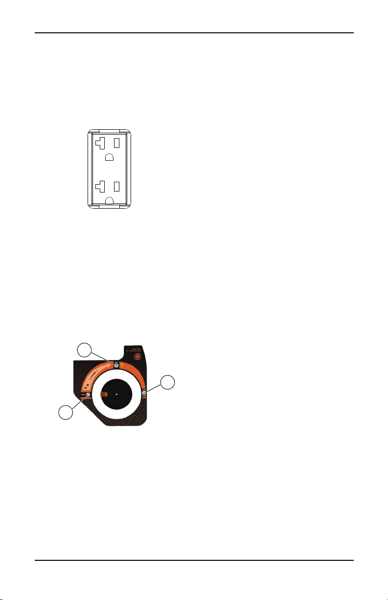
120 VAC, Duplex Receptacle
The 120 Volt outlet is overload protected by
the inverter module electronic control. See
Figure 2-4. Each receptacle will power 120
Volt AC, single phase, 60 Hz electrical loads
requiring up to 1600 watts (1.6 kW).
Figure 2-4. 120 VAC, Duplex Receptacle
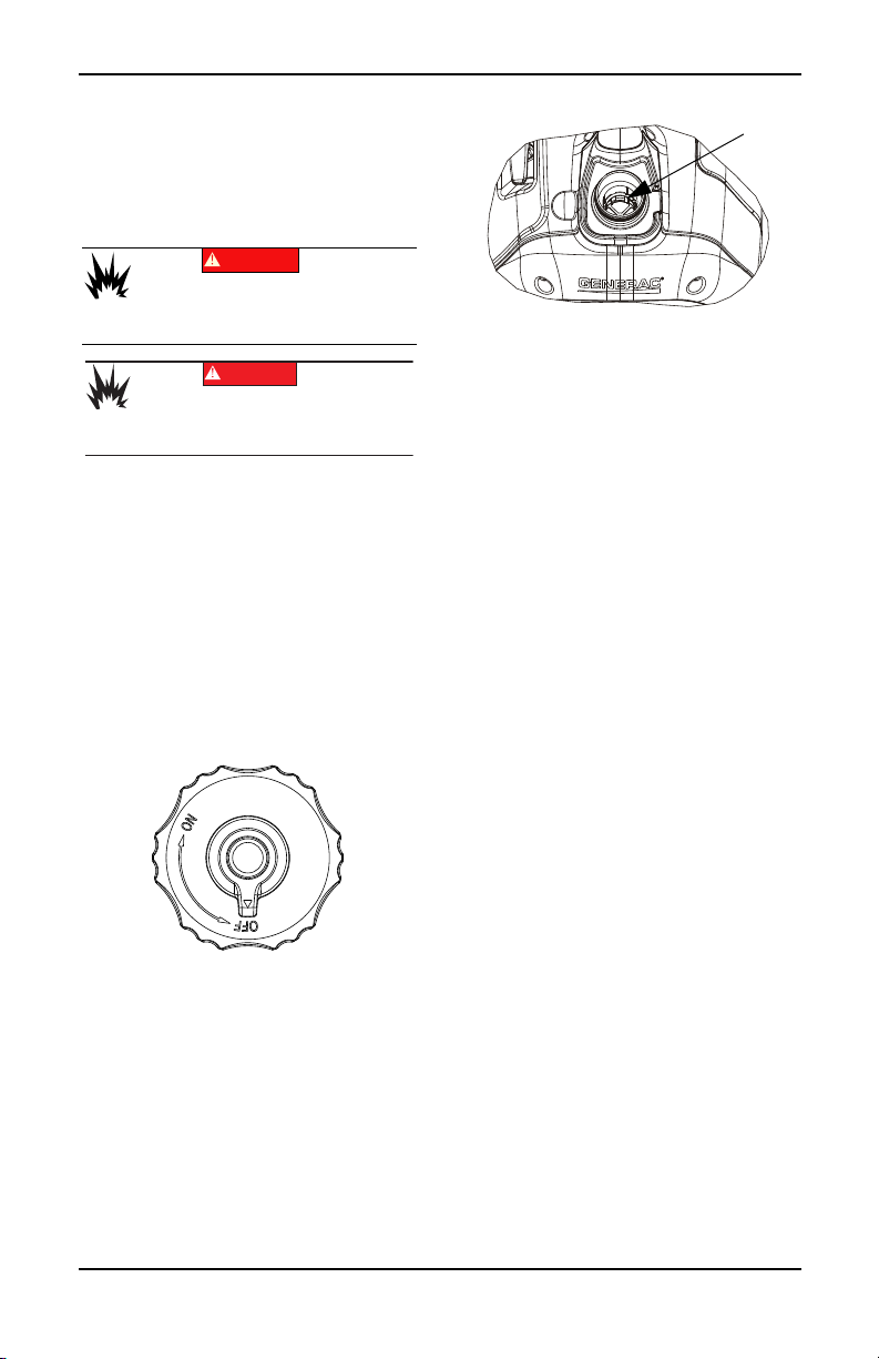
PowerDial
The PowerDial controls the ON/OFF functions, choke and fuel valve operation. See Fig-
ure 2-5.
• The START position (1) is used to start the
engine. In this position, the fuel is on and
the choke is fully on (closed).
• The RUN position (2) for normal operation
and to gradually reduce the use of the
choke.
• The STOP position (3) stops the engine
and shuts off fuel flow.
Figure 2-5. PowerDial (example)
PowerBar
See Figure 2-6. The PowerBar (8) indicates
the amount of power being used from the generator. Each section is approximately 12.5%.
Economy Switch
The economy switch has 3 modes of operation:
• Economy: The quietest mode and best
when running appliances or equipment that
are resistive loads (non-motor starting),
(example: TV, video game, light, radio).
• Standard: Best when running a both inductive (motor-starting loads) and resistive
(non-motor starting loads), especially when
these loads are turning on and off (example: RV, air conditioner, hairdryer).
• Turbo: Best when running inductive loads
(appliances or equipment with motor-starting) that are continually running (examples:
drill, blender, saw).
Generator Status Lights
See Figure 2-6.
• Overheat LED (red): Illuminates when unit
temperatures exceed normal operating
conditions (1). The ready LED will turn off
and the inverter will cut power to the outlets. Check for airflow obstructions at front
and rear panels. The engine will remain
running to cool the unit with the overheat
LED illuminated. Once the unit has reached
normal operating temperatures, the overheat LED will turn off. The reset button
must then be pressed for 1 second and
released to clear the fault and restore output power.
• Low Oil Level LED (orange): Illuminates
when oil level is below safe operating level.
Engine shuts down (2).
• Ready LED (green): Indicates output from
generator (3) (unless there is a low oil or
overload condition).
• Overload LED (red): Indicates system
overload (4). During motor starting it is normal for the overload LED to illuminate for a
few seconds. If LED stays illuminated and
the ready LED turns off, the engine will continue to run without output power. Remove
all applied loads and determine if attached
devices exceed recommended output
power. Review for any faulty or shorted
connections. Press and hold the reset button for 3 seconds and release. The red
overload LED should turnoff. Loads can be
re-applied once the green ready LED illuminates. If the red LED returns, contact an
IASD.
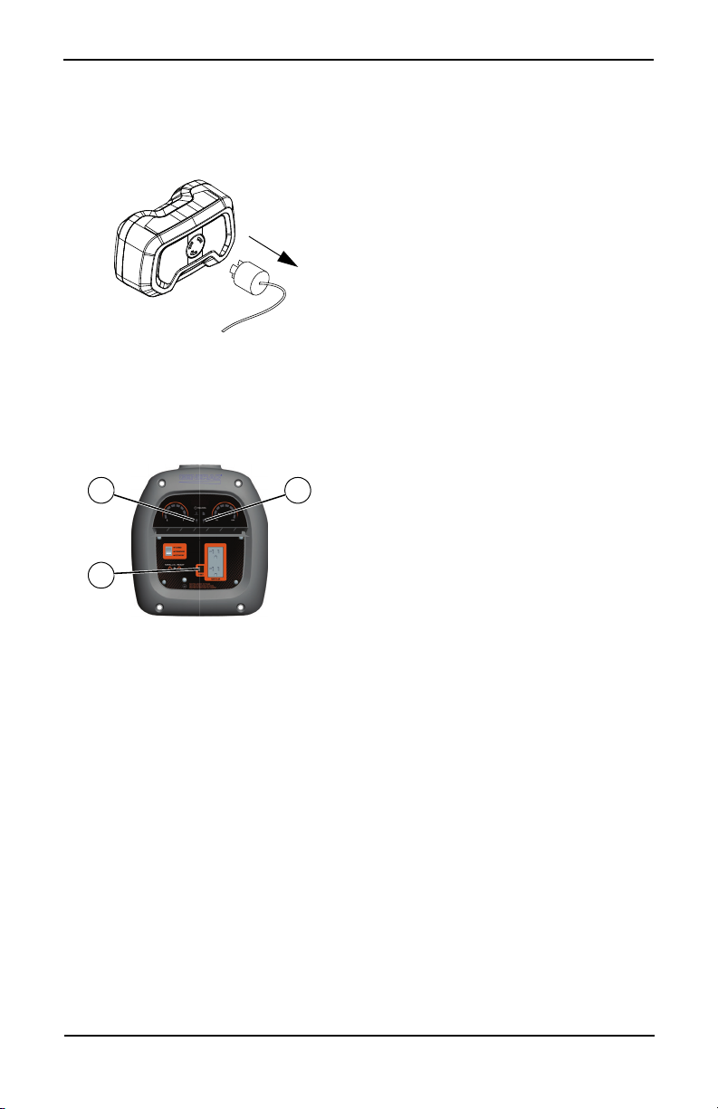
Run Time Display
See Figure 2-6. At startup the Run Time Display (7) shows the total engine hours of the
unit, then transitions to show the Run Time
Remaining.
6 Owner’s Manual for Portable Generator
Page 9

Figure 2-6. Status Indicators
003040
6
5
1
3
7
4
2 8
001792
Fuel Sensor and Fuel Gauge
See Figure 2-6. The fuel sensor (5) and gas
gauge (6) indicate fuel remaining in the internal fuel tank. The Run Time Clock displays the
amount of run time remaining for the current
fuel level and applied load.
NOTE: The run time clock will update if load is
changed to reflect different fuel consumption.
Add Engine Oil
CAUTION
Engine damage. Verify proper type and quantity of
engine oil prior to starting engine. Failure to do so
could result in engine damage.
NOTE: The generator is shipped without oil in
the engine. Add oil slowly and verify oil level
often during filling process to ensure overfilling
does not occur.
1. Place generator on a level surface.
2. Clean area around oil fill and oil drain plug.
3. Remove oil fill cap and wipe dipstick clean.
See Figure 2-7.
(000135)
Remove Contents from Carton
1. Open carton completely by cutting each
corner from top to bottom.
2. Remove and verify carton contents prior to
assembly. Carton contents should contain
the following:
TABLE 3. Accessories
Item Qty.
Main Unit 1
Owner’s Manual 1
SAE 30 Oil 1
Oil Funnel 1
Product Registration Card 3
Service Warranty 1
Emissions Warranty 1
3. Call Generac Customer Service 1-888GENERAC (1-888-436-3722) with the unit
model and serial number for any missing
carton contents.
4. Record model, serial number, and date of
purchase on front cover of this manual.
000804
Figure 2-7. Remove Dipstick
4. Screw funnel into oil fill opening. Add recommended engine oil as necessary. Climate determines proper engine oil
viscosity. See chart to select correct viscosity.
NOTE: Use petroleum based oil (supplied) for
engine break-in before using synthetic oil.
SAE 30
10W-30
Synthetic 5W-30
000399
5. To check oil level, remove funnel and
insert dipstick into oil filler neck without
screwing it in. See Figure 2-8.
.
Figure 2-8. Safe Operating Range
Owner’s Manual for Portable Generator 7
Page 10
6. Remove dipstick and verify oil level is
(000105)
DANGER
Explosion and Fire. Fuel and vapors are
extremely flammable and explosive. Add fuel
in a well ventilated area. Keep fire and spark
away. Failure to do so will result in death
or serious injury.
(000166b)
Explosion and Fire. Do not overfill fuel tank. Fill to
1/2 inch from top of tank to allow for fuel expansion.
Overfilling may cause fuel to spill onto engine causing
fire or explosion, which will result in death or
serious injury.
001112
000820
within safe operating range.
NOTE: Verify oil level often during filling process to ensure overfilling does not occur.
7. Install oil fill cap/dipstick and hand-tighten.
Fuel
DANGER
Fuel requirements are as follows:
• Clean, fresh, unleaded gasoline.
• Minimum rating of 87 octane/87 AKI (91
RON).
• Up to 10% ethanol (gasohol) is acceptable.
• DO NOT use E85.
• DO NOT use a gas oil mix.
• DO NOT modify engine to run on alternate
fuels. Stabilize fuel prior to storage.
1. Verify unit is OFF and cooled entirely prior
to fueling.
2. Place unit on level ground in a well venti-
lated area.
3. Clean area around fuel cap and turn vent
on fuel cap to ON. See Figure 2-9.
Figure 2-10. Internal Fuel Tank Level
NOTE: Allow spilled fuel to evaporate before
starting unit.
IMPORTANT NOTE: It is important to prevent gum deposits from forming in fuel
system parts such as the carburetor, fuel
hose or tank during storage. Alcoholblended fuels (called gasohol, ethanol or
methanol) can attract moisture, which
leads to separation and formation of acids
during storage. Acidic gas can damage the
fuel system of an engine while in storage.
To avoid engine problems, the fuel system
should be emptied before storage of 30
days or longer. See the Storage section.
Never use engine or carburetor cleaner
products in the fuel tank as permanent
damage may occur.
Figure 2-9. Fuel Cap
4. Turn cap slowly to remove.
5. Slowly add recommended fuel. DO NOT
overfill.
— Fill to red insert inside filler neck. See
Figure 2-10.
6. Install fuel cap.
7. Turn vent on fuel cap to OFF for transpor-
tation and storage.
8 Owner’s Manual for Portable Generator
Page 11

Section 3 Operation
(000179b)
DANGER
Asphyxiation. The exhaust system must be properly
maintained. Do not alter or modify the exhaust system
as to render it unsafe or make it noncompliant with
local codes and/or standards. Failure to do so will
result in death or serious injury.
WARNING
(000118a)
Risk of fire. Do not use generator without
spark arrestor installed. Failure to do so
could result in death or serious injury.
(000178a)
Asphyxiation. Always use a battery operated carbon
monoxide alarm indoors and installed according to
the manufacturer’s instructions. Failure to do so could
result in death or serious injury.
WARNING
(000110)
WARNING
Risk of Fire. Hot surfaces could ignite
combustibles, resulting in fire. Fire could
result in death or serious injury.
(000108)
WARNING
Hot Surfaces. When operating machine, do not
touch hot surfaces. Keep machine away from
combustibles during use. Hot surfaces could
result in severe burns or fire.
(000136)
CAUTION
Equipment and property damage. Disconnect electrical
loads prior to starting or stopping unit. Failure to do so
could result in equipment and property damage.
Operation and Use Questions
Call Generac customer service at 1-888-GENERAC (1-888-436-3722) with questions or
concerns about equipment operation and
maintenance.
Before Starting Engine
1. Verify engine oil level is correct.
2. Verify fuel level is correct.
3. Verify unit is secure on level ground, with
proper clearance and is in a well ventilated
area.
Prepare Generator for Use
Asphyxiation. Running engines produce
carbon monoxide, a colorless, odorless,
poisonous gas. Carbon monoxide, if not
avoided, will result in death or serious injury.
Owner’s Manual for Portable Generator 9
DANGER
(000103)
Grounding the Generator When Used as a Portable
The generator is equipped with a terminal for
the connection of a grounding electrode system. Article 250.34 (A) does not require the
frame of the generator to be connected to a
grounding electrode system when the generator only supplies power to cord and plug connected equipment through the receptacles on
the generator.
When the generator supplies power to a 3pole manual transfer switch or distribution
panel boards for temporary power, a grounding electrode system shall be installed and
connected to the grounding electrode terminal
on the generator. See NEC 250.30, 250.34
and 250.52 for clarification.
See Figure 3-1.
• Neutral Bonded to Frame
000808
Figure 3-1. Grounding the Generator
Know Generator Limits
Overloading a generator can result in damage
to the generator and connected electrical
devices. Observe the following to prevent
overload:
• Add up the total wattage of all electrical
devices to be connected at one time. This
total should NOT be greater than the generator's wattage capacity.
• The rated wattage of lights can be taken
from light bulbs. The rated wattage of tools,
appliances, and motors can be found on a
data label or decal affixed to the device.
• If the appliance, tool, or motor does not
give wattage, multiply volts times ampere
rating to determine watts (volts x amps =
watts).
• Some electric motors, such as induction
types, require about three times more watts
of power for starting than for running. This
surge of power lasts only a few seconds
when starting such motors. Make sure to
allow for high starting wattage when selecting electrical devices to connect to the generator:
1. Figure the watts needed to start the largest
motor.
Page 12
2. Add to that figure the running watts of all
(000183)
WARNING
Recoil Hazard. Recoil could retract unexpectedly.
Kickback could result in death or serious injury.
(000136)
CAUTION
Equipment and property damage. Disconnect electrical
loads prior to starting or stopping unit. Failure to do so
could result in equipment and property damage.
other connected loads.
Wattage Reference Guide is provided to assist
in determining how many items the generator
can operate at one time.
NOTE: All figures are approximate. See data
label on appliance for wattage requirements.
Wattage Reference Guide
Device Running
*Air Conditioner (12,000 Btu) 1700
*Air Conditioner (24,000 Btu) 3800
*Air Conditioner (40,000 Btu) 6000
Battery Charger (20 Amp) 500
Belt Sander (3") 1000
Chain Saw 1200
Circular Saw (6-1/2") 800 to 1000
*Clothes Dryer (Electric) 5750
*Clothes Dryer (Gas) 700
*Clothes Washer 1150
Coffee Maker 1750
*Compressor (1 HP) 2000
*Compressor (3/4 HP) 1800
*Compressor (1/2 HP) 1400
Curling Iron 700
*Dehumidifier 650
Disc Sander (9") 1200
Edge Trimmer 500
Electric Blanket 400
Electric Nail Gun 1200
Electric Range (per element) 1500
Electric Skillet 1250
*Freezer 700
*Furnace Fan (3/5 HP) 875
*Garage Door Opener 500 to 750
Hair Dryer 1200
Hand Drill 250 to 1100
Hedge Trimmer 450
Impact Wrench 500
Iron 1200
*Jet Pump 800
Lawn Mower 1200
Light Bulb 100
Microwave Oven 700 to 1000
*Milk Cooler 1100
Oil Burner on Furnace 300
Watts
Oil Fired Space Heater (140,000
Btu)
Oil Fired Space Heater (85,000 Btu) 225
Oil Fired Space Heater (30,000 Btu) 150
*Paint Sprayer, Airless (1/3 HP) 600
Paint Sprayer, Airless (hand-held) 150
Radio 50 to 200
*Refrigerator 700
Slow Cooker 200
*Submersible Pump (1-1/2 HP) 2800
*Submersible Pump (1 HP) 2000
*Submersible Pump (1/2 HP) 1500
*Sump Pump 800 to 1050
*Table Saw (10") 1750 to 2000
Television 200 to 500
Toaster 1000 to 1650
Weed Trimmer 500
* Allow 3 times the listed watts for starting these
devices.
400
Transporting/Tipping of the Unit
Do not store or transport the unit at an angle
greater than 15 degrees.
Starting Pull Start Engines
1. Turn fuel cap vent ON. See Figure 2-9.
2. See Figure 3-2. Rotate the PowerDial to
START (1).
3. Switch Economy switch to TURBO.
4. Firmly grasp recoil handle and pull slowly
until increased resistance is felt. Pull rapidly up and away.
10 Owner’s Manual for Portable Generator
Page 13
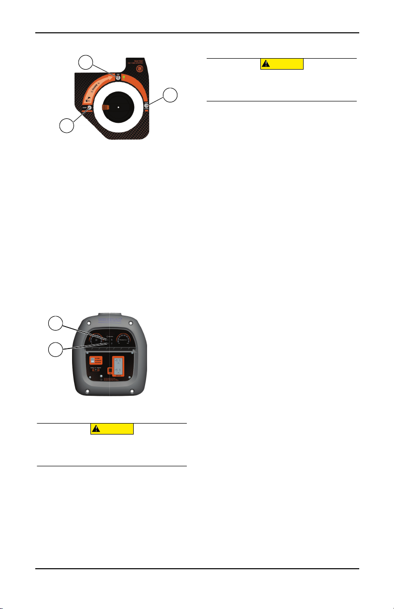
Figure 3-2. PowerDial Positions
000663
2
1
3
003039
A
B
(000136)
CAUTION
Equipment and property damage. Disconnect electrical
loads prior to starting or stopping unit. Failure to do so
could result in equipment and property damage.
(000136)
CAUTION
Equipment and property damage. Disconnect electrical
loads prior to starting or stopping unit. Failure to do so
could result in equipment and property damage.
5. See Figure 3-2. When engine starts, rotate
PowerDial to RUN (2). Choke operation is
reduced as PowerDial is rotated towards
RUN. If engine falters, rotate PowerDial
counterclockwise to START (1) to increase
choke. When engine runs smoothly, rotate
back to RUN.
NOTE: If engine fires, but does not continue to
run, rotate the PowerDial to START and
repeat starting instructions.
IMPORTANT NOTE: Do not overload generator or individual panel receptacles. See
Figure 3-3. If an overload occurs, the over-
load LED (A) will illuminate and AC output
ceases. Press and hold the reset button for
3 seconds to reset the fault condition while
the unit is running. Read Know Generator
Limits carefully.
.
Figure 3-3. Shutdown Fault
Generator Shut Down
1. Shut off all loads and unplug electrical
loads from generator panel receptacles.
2. Let engine run at no-load for several minutes to stabilize internal temperatures of
engine and generator.
3. See Figure 3-2 Rotate PowerDial clockwise to STOP (3).
4. Turn fuel cap OFF.
Restarting Hot Engines
1. See Figure 3-2. Turn PowerDial counterclockwise, from STOP until just past RUN.
This will open the fuel valve and permit
starting.
2. Firmly grasp recoil handle and pull slowly
until increased resistance is felt. Pull rapidly up and away.
3. Turn PowerDial clockwise to RUN.
Low Oil Level Shutdown System
The engine is equipped with a low oil level
sensor that shuts down the engine automatically when the oil level drops below a specified level to prevent engine damage. See
Figure 3-3 (B). The engine will not run until the
oil has been filled to the proper level.
If the engine shuts down and there is sufficient
fuel, check engine oil level.
Parallel Operation
For output power up to 3200W, two iQ2000
inverters can operate in parallel using Generac’s Smart Parallel Kit (optional). See the
Smart Parallel Kit Operator ’s Manual or contact an IASD.
NOTE: All connections to the parallel kit
should be made while both inverters are
turned off and all loads disconnected.
1. The economy switch for both units must be
matching and set to either standard or
turbo.
2. Make appropriate parallel connections to
the 120V duplex outlets on each iQ2000
inverter as outlined in the owner’s manual
supplied with the kit.
NOTE: Do not disconnect any parallel kit connections once the units are running.
3. Start both units per starting instructions.
Once the green output indicator illuminates, devices can be connected and
turned on using the parallel kit outlet.
4. Follow Generator Shut Down instructions.
NOTE: Load applied to the parallel kit is not to
exceed 3200 watts.
NOTE: Only use Generac approved parallel
kit.
Owner’s Manual for Portable Generator 11
Page 14
Parallel Reset Procedure
003594
003039
1
3 2
1. Turn OFF all loads applied to generators.
2. See Figure 3-4. Remove the 30A plug from
parallel kit. DO NOT unplug parallel kit
from generators.
.
Figure 3-4. Remove 30A Plug
3. See Figure 3-5. Press and hold the Reset
button (1) on unit A for three (3) seconds,
then release.
4. See Figure 3-5. Wait for the red Overload
light (2) to turn OFF and the green Ready
light (3) to turn ON.
.
Figure 3-5. Reset Button and Status Lights
5. See Figure 3-5. Repeat steps 3 and 4 for
unit B.
6. Insert 30A plug into parallel kit.
7. Apply loads. After each load is applied,
observe power usage displayed on Powerbar. DO NOT exceed 100%.
NOTE: See Figure 3-5. If red Overload light (2)
persists after five (5) attempts, contact Generac customer service at 1-888-GENERAC (1888-436-3722).
12 Owner’s Manual for Portable Generator
Page 15

Section 4 Maintenance and Troubleshooting
(000142a)
Personal injury. Do not insert any object through the
air cooling slots. Generator can start at any time and
could result in death, serious injury, and unit damage.
Maintenance
Regular maintenance will improve performance and extend engine/equipment life.
Generac Power Systems, Inc. recommends
that all maintenance work be performed by an
Independent Authorized Service Dealer
(IASD). Regular maintenance, replacement,
or repair of the emissions control devices and
systems may be performed by any repair shop
or person of the owner’s choosing. To obtain
emissions control warranty service free of
charge, the work must be performed by an
IASD. See the emissions warranty.
NOTE: Call 1-888-GENERAC (1-888-436-
3722) with questions about component
replacement.
Maintenance Schedule
Follow maintenance schedule intervals,
whichever occurs first according to use.
NOTE: Adverse conditions will require more
frequent service.
NOTE: All required service and adjustments
should be each season as detailed in the following chart.
At Each Use
Check engine oil level
Every 50 Hours
Clean/Replace Air Filter**
Every 100 Hours or Every Season*
Change oil ǂ
Replace Spark Plug
Clean Spark Arrestor
Valve Clearance Adjustment
Every 200 Hours or Every Season
Inspect/clean air cleaner filter**
Replace Fuel Filter +
ǂ Change oil after first 30 hours of operation,
then every season.
+ To be performed by IASD
* Change oil every month when operating
under heavy load or in high temperatures.
** Clean more often under dirty or dusty oper-
ating conditions. Replace air filter parts if
they cannot be adequately cleaned.
*** Check valve clearance and adjust if neces-
sary after first 50 hours of operation and
every 100 hours thereafter.
Preventive Maintenance
Dirt or debris can cause improper operation
and equipment damage. Clean generator
daily or before each use. Keep area around
and behind muffler free from combustible
debris. Inspect all cooling air openings on
generator.
WARNING
• Use a damp cloth to wipe exterior surfaces
clean.
• Use a soft bristle brush to loosen caked on
dirt, oil, etc.
• Use a vacuum to pick up loose dirt and
debris.
• Low pressure air (not to exceed 25 psi)
may be used to blow away dirt. Inspect
cooling air slots and openings on generator.
These openings must be kept clean and
unobstructed.
NOTE: DO NOT use a garden hose to clean
generator. Water can enter engine fuel system
and cause problems. If water enters generator
through cooling air slots, some water will be
retained in voids and crevices of rotor and stator winding insulation. Water and dirt buildup
on generator internal windings will decrease
insulation resistance of windings.
Engine Maintenance
WARNING
Accidental start-up. Disconnect spark plug wires when
working on unit. Failure to do so could result in death
or serious injury.
Engine Oil Recommendations
To maintain the product warranty, the engine oil
should be serviced in accordance with the recommendations of this manual. For your convenience, maintenance kits designed and intended
for use on this product are available from the
manufacturer that include engine oil, oil filter, air
filter, spark plug(s), a shop towel and funnel.
These kits can be obtained from an Independent
Authorized Service Dealer (IASD).
(000141)
Owner’s Manual for Portable Generator 13
Page 16

.
(000139)
WARNING
Risk of burns. Allow engine to cool before
draining oil or coolant. Failure to do so could
result in death or serious injury.
001792
SAE 30
10W-30
Synthetic 5W-30
000399
Inspect Engine Oil Level
Inspect engine oil level prior to each use, or
every 8 hours of operation.
1. Place generator on a level surface.
2. Clean area around oil fill, and oil drain
plug.
3. Remove oil fill cap and wipe dipstick clean.
See Figure 4-1.
7. Replace oil fill cap and hand-tighten.
NOTE: Some units have more than one oil fill
location. It is only necessary to use one oil fill
point.
Change Engine Oil
WARNING
Accidental start-up. Disconnect spark plug wires when
working on unit. Failure to do so could result in death
or serious injury.
When using generator under extreme, dirty,
dusty conditions, or in extremely hot weather,
change oil more frequently.
NOTE: Don’t pollute. Conserve resources.
Return used oil to collection centers.
Change oil while engine is still warm from running, as follows:
1. Place generator on a level surface.
2. Disconnect the spark plug wire from the
spark plug and place the wire where it
cannot contact spark plug.
3. Clean area around oil fill and oil drain plug.
4. Remove oil fill cap and wipe dipstick clean.
Screw funnel into oil fill opening. See Fig-
ure 4-3.
(000141)
000804
Figure 4-1. Engine Oil Fill
4. To check oil level, insert dipstick into oil
filler neck without screwing it in. See Fig-
ure 4-2.
Figure 4-3. Oil Fill Opening With Funnel
5. Tip unit and drain oil completely into a suitable container.
6. Once oil is sufficiently drained from unit, tip
unit back to a level position.
7. Add recommended engine oil as necessary.
8. To check oil level, remove funnel and
insert dipstick into oil filler neck without
screwing it in. See Figure 4-2.
9. Remove dipstick and verify oil level is
within safe operating range.
NOTE: Verify oil level often during filling process to ensure overfilling does not occur.
10. Replace oil fill cap and hand-tighten.
Figure 4-2. Safe Operating Range
5. Remove dipstick and verify oil level is
within safe operating range.
6. Add recommended engine oil as necessary.
NOTE: Verify oil level often during filling process to ensure overfilling does not occur.
14 Owner’s Manual for Portable Generator
11. Wipe up any spilled oil.
12. Properly dispose of oil in accordance with
all applicable regulations.
000822
Page 17

Air Filter
000666
ABA
C
D
000211
000668
A
B
C
D
Engine will not run properly and may be damaged if run with a dirty air filter. Service air filter more frequently in dirty or dusty conditions.
To service air filter:
1. See Figure 4-4. Turn knob and remove
service door (A).
2. Unscrew bolt (B) and remove air filter
cover (C).
3. Wash filter (D) in soapy water. Squeeze
dry in clean cloth (DO NOT TWIST).
4. Clean air filter cover before re-installing it.
NOTE: To order a new air filter, contact the
nearest authorized service center at 1-888GENERAC (1-888-436-3722).
Figure 4-4. Air Filter Assembly
Service Spark Plug
To service spark plug:
1. Clean area around spark plug.
2. Remove and inspect spark plug.
3. Inspect electrode gap with wire feeler
gauge and reset spark plug gap to 0.6 -
0.7mm (0.024 - 0.028 in). See Figure 4-5.
Inspect Muffler and Spark Arrester
NOTE: It is a violation of California Public
Resource Code, Section 4442, to use or operate the engine on any forest-covered, brushcovered, or grass-covered land unless the
exhaust system is equipped with a spark
arrester, as defined in Section 4442, maintained in effective working order. Other states
or federal jurisdictions may have similar laws.
Contact original equipment manufacturer,
retailer, or dealer to obtain a spark arrester
designed for exhaust system installed on this
engine.
NOTE: Use ONLY original equipment replacement parts.
Inspect muffler for cracks, corrosion, or other
damage. Remove spark arrester, if equipped,
inspect for damage or carbon blockage.
Replace parts as required.
Inspect Spark Arrester Screen
Hot Surfaces. When operating machine, do not
touch hot surfaces. Keep machine away from
combustibles during use. Hot surfaces could
result in severe burns or fire.
WARNING
(000108)
Clean Spark Arrestor Screen (50
State)
The engine exhaust muffler has a spark arrestor screen. Inspect and clean the screen every
100 hours of operation or once each year,
whichever comes first.
To service spark arrestor:
1. See Figure 4-6. Remove the clamp (A) to
remove retainer (B).
2. Slide spark arrestor screens (C) out from
the muffler outlet tube (D).
3. Inspect screens and replace if torn, perforated or otherwise damaged. Do NOT use
a defective screen. If screen is not damaged, clean with a commercial solvent.
4. Replace the screens, and retainer, and
secure with clamp.
Figure 4-5. Spark Plug
NOTE: Replace spark plug if electrodes are
pitted, burned or porcelain is cracked. Use
ONLY recommended replacement plug. See
Specifications.
4. Install spark plug finger tight, and tighten
an additional 3/8 to 1/2 turn using spark
plug wrench.
Owner’s Manual for Portable Generator 15
Figure 4-6. Spark Arrestor Screen
Page 18

Val ve Cle aranc e
(000181)
WARNING
Vision Loss. Eye protection is required to avoid
spray from spark plug hole when cranking engine.
Failure to do so could result in vision loss.
Important: Please contact an Independent
Authorized Service Dealer for service assistance. Proper valve clearance is essential for
prolonging the life of the engine.
Check valve clearance after the first fifty-hours
of operation. Adjust as necessary.
• Intake — 0.10 ± 0.02mm (cold), (0.004" ±
0.001" inches)
• Exhaust — 0.10 ± 0.02mm (cold) (0.004" ±
0.001" inches)
Storage
General
Explosion and Fire. Fuel and vapors are extremely
flammable and explosive. Store fuel in a well
ventilated area. Keep fire and spark away. Failure
to do so will result in death or serious injury.
Risk of Fire. Verify machine has properly
cooled before installing cover and storing
machine. Hot surfaces could result in fire.
It is recommended to start and run the generator for 30 minutes, every 30 days. If this is not
possible, refer to the following list to prepare
unit for storage.
• DO NOT place a storage cover on a hot
generator. Allow unit to cool to room temperature before storage.
• DO NOT store fuel from one season to
another unless properly treated.
• Replace fuel container if rust is present.
Rust in fuel will cause fuel system problems.
• Cover unit with a suitable protective, mois-
ture resistant cover.
• Store unit in a clean, dry area.
• Always store generator and fuel away from
heat and ignition sources.
DANGER
(000143)
WARNING
(000109)
2. Remove spark plug.
3. Pour tablespoon (5-10cc) of clean engine
oil or spray a suitable fogging agent into
cylinder.
4. Pull starter recoil several times to distribute oil in cylinder.
5. Install spark plug.
6. Pull recoil slowly until resistance is felt.
This will close valves so moisture cannot
enter engine cylinder. Gently release
recoil.
Change Oil
Change engine oil before storage. See,
Change Engine Oil.
Prepare Fuel System/Engine for
Storage
Fuel stored over 30 days can go bad and
damage fuel system components. Keep fuel
fresh, use fuel stabilizer.
If fuel stabilizer is added to fuel system, prepare and run engine for long term storage.
Run engine for 10-15 minutes to circulate stabilizer throughout fuel system. Adequately
prepared fuel can be stored up to 24 months.
NOTE: If fuel has not been treated with fuel
stabilizer, it must be drained into an approved
container. Run engine until it stops from lack
of fuel. Use of fuel stabilizer in fuel storage
container is recommended to keep fuel fresh.
1. Change engine oil.
16 Owner’s Manual for Portable Generator
Page 19

Troubleshooting
PROBLEM CAUSE CORRECTION
Engine won't start. 1. PowerDial turned off.
2. Out of fuel.
3. Defective spark plug.
4. Plugged fuel filter.
5. Defective or stuck PowerDial
assembly.
6. Incorrect engine oil level.
7. Defective ignition coil.
8. Fuel cap vent OFF.
9. Carb is flooded.
10. Throttle plate closed.
1. Turn on PowerDial.
2. Fill fuel tank.
3. Replace spark plug.
4. Contact IASD.
5. Contact IASD.
6. Check/fill engine oil.
7. Contact IASD.
8. Turn fuel cap vent ON.
9. Drain carb.
10. Open throttle plate (push
toward back of unit).
Engine starts, then shuts
down.
Engine will not start; or
starts and runs rough.*
No AC output. 1. Generator is overloaded.
Fuel leaks from drain
hoses.
* Engine speed increases and decreases — This is normal as generator starts up and loads vary.
1. Out of fuel.
2. Incorrect engine oil level.
3. Contaminated fuel.
4. Defective low oil level switch.
5. Fuel cap vent OFF.
1. Choke is stuck or left on.
2. Dirty or clogged air filter.
3. Defective or dirty spark plug.
4. Dirty fuel filter.
5. Dirty or gummed up carburettor.
6. Unit not warmed up.
7. Fuel cap vent OFF.
2. Inverter module is overheated.
3. Short circuit in electrical
device.
4. Defective inverter assembly.
1. Carburetor drain in bowl is not
closed.
1. Fill fuel tank.
2. Check engine oil level.
3. Contact IASD.
4. Contact IASD.
5. Turn fuel cap vent ON.
1. Turn choke off.
2. Clean or replace air filter.
3. Replace spark plug.
4. Replace fuel and fuel filter.
5. Clean carburetor.
6. Gradually adjust PowerDial
and reduce choke until engine
runs smoothly in RUN position.
7. Turn fuel cap vent ON.
1. Disconnect all loads. Shut
down generator to reset module. Reduce loads, restart
generator.
2. Verify service door is ON. Let
cool 15 minutes by running
engine without AC output.
Press and hold Reset button
on control panel, restart generator.
3. Verify condition of extension
cords and items being powered. Press and hold Reset
button on control panel.
4. Contact IASD.
1. Turn valve clockwise to close.
Owner’s Manual for Portable Generator 17
Page 20

Part No. 10000011496 Rev. B 12/15/2017 ©2017 Generac Power Systems, Inc. All rights reserved
Specifications are subject to change without notice.
No reproduction allowed in any form without prior
written consent from Generac Power Systems, Inc.
Generac Power Systems, Inc.
S45 W29290 Hwy. 59
1-888-GENERAC (1-888-436-3722)
Waukesha, WI 53189
www.generac.com
Page 21

Generador portátil iQ2000
000853
ADVERTENCIA
(000209b)
Fallecimiento. Este producto no se ha diseñado
para que se utilice en aplicaciones de apoyo
vital crítico. En caso de hacerlo, podría
provocar la muerte o lesiones graves.
Manual del usuario
MODELO: __________________________
SERIE: ____________________________
FECHA DE LA COMPRA: _____________
Registre su producto Generac en:
WWW.GENERAC.COM
1-888-GENERAC
(1-888-436-3722)
GUARDE ESTE MANUAL PARA PODER CONSUL TARLO EN EL FUTURO
Page 22

Índice de contenidos
Sección 1 Introducción
y seguridad .................................... 1
Introducción .................................... 1
Normas de seguridad ...................... 1
Símbolos de seguridad
y significados ................................... 1
Peligros derivados de las emisiones
de escape y la ubicación ................. 2
Peligros eléctricos ...........................3
Peligros de incendio ........................ 3
Índice de normas ............................. 3
Sección 2 Información general y
configuración ................................4
Conozca su generador .................... 5
Emisiones ........................................ 5
Enchufes de conexión ..................... 6
Selector de potencia ....................... 6
Barra de potencia ............................ 6
Interruptor de ahorro ....................... 6
Luces de estado del generador ....... 6
Pantalla de tiempo de
funcionamiento ................................ 7
Sensor de combustible e indicador
de combustible ................................7
Sacar el contenido de la caja .......... 7
Añadir aceite de motor .................... 7
Combustible .................................... 8
Sección 3 Funcionamiento ...........9
Preguntas sobre uso
y funcionamiento .............................9
Antes de arrancar el motor ..............9
Preparación del generador
para su uso ......................................9
Conexión a tierra del generador
cuando se utiliza como aparato
portátil ..............................................9
Conozca los límites del generador ..9
Transporte o inclinación de
la unidad ........................................10
Arranque de motores con el
tirador de arranque ........................11
Volver a arrancar motores
calientes ........................................11
Sistema de cierre por nivel bajo
de aceite ........................................12
Funcionamiento en paralelo ..........12
Procedimiento de reinicio
paralelo ..........................................12
Sección 4 Mantenimiento
y solución de problemas ............13
Mantenimiento ...............................13
Programa de mantenimiento .........13
Mantenimiento preventivo .............13
Mantenimiento del motor ...............14
Almacenamiento ............................16
Solución de problemas ..................18
El funcionamiento, reparación y mantenimiento de
este equipo puede exponerlo a productos químicos
entre los que se incluyen gases de escape del motor,
monóxido de carbono, ftalatos y plomo, los cuales
son considerados por el Estado de California como
causantes de cáncer y malformaciones congénitas y
otros daños reproductivos. Para minimizar los efectos
de la exposición a tales sustancias, evite respirar
gases de escape, no deje que el motor funcione al
ralentí excepto si fuera necesario, realice las tareas
de mantenimiento del equipo en un área bien ventilada
y lleve guantes o lávese las manos con frecuencia
cuando realice tareas de mantenimiento en el equipo.
Si desea obtener más información, vaya a
www.P65Warnings.ca.gov.
ADVERTENCIA
(000393)
Page 23

Sección 1 Introducción y seguridad
(000001)
PELIGRO
Indica una situación peligrosa que, si no se evita, ocasionará la
muerte o lesiones graves.
(000002)
ADVERTENCIA
Indica una situación peligrosa que, si no se evita, podría
ocasionar la muerte o lesiones graves.
(000003)
PRECAUCIÓN
Indica una situación de riesgo que, si no se evita, puede
producir lesiones leves o moderadas.
000657
Asfixia. Los motores funcionando producen
monóxido de carbono, un gas incoloro, inodoro, y
venenoso. El monóxido de carbono, si no se evita,
ocasionará la muerte o lesiones graves.
(000103)
PELIGRO
Introducción
Gracias por haber adquirido un producto de
Generac Power Systems Inc. Esta unidad se
ha diseñado para proporcionar un
funcionamiento eficiente, de alto rendimiento
y con una vida útil larga si se conserva
adecuadamente.
ADVERTENCIA
Consulte el manual. Lea y comprenda completamente
el manual antes de usar el producto. No comprender
completamente el manual puede provocar la muerte o
lesiones graves.
(000100a)
Si no entendiera alguno de los apartados de
este manual, póngase en contacto con el
servicio técnico independiente autorizado más
cercano, o con el servicio de atención al
cliente de Generac llamando al 1-888GENERAC (1-888-436-3722), o visitando
www.generac.com para plantear cualquier
pregunta o duda que tenga.
El propietario es responsable del
mantenimiento adecuado y del uso seguro del
equipo. Antes de poner en funcionamiento,
revisar o guardar el generador:
• Revise atentamente todas las advertencias
que aparecen en este manual y en el
producto.
• Familiarícese con este manual y con la
unidad antes de utilizarla.
• Consulte Introducción y seguridad para
obtener instrucciones sobre los
procedimientos de montaje. Siga
estrictamente las instrucciones.
Guarde estas instrucciones para consultarlas
en el futuro. Entregue SIEMPRE este manual
a cualquier persona que utilice la máquina.
La información que aparece en este manual es
precisa y está basada en productos fabricados
en el momento en el que se editó esta
publicación. El fabricante se reserva el derecho
de hacer las actualizaciones técnicas, las
correcciones y las revisiones de los productos
que considere necesarias sin previo aviso.
Normas de seguridad
El fabricante no puede prever todas las
posibles circunstancias que pueden suponer
un peligro. Por tanto, las advertencias de este
manual, y de las etiquetas y los adhesivos
pegados en la unidad no incluyen todos los
peligros. Si se utiliza un procedimiento, método
de trabajo o técnica de funcionamiento no
recomendados específicamente por el
fabricante, compruebe que sean seguros para
otros usuarios. También asegúrese de que el
procedimiento, método de trabajo o técnica
operativa utilizados no disminuyan la seguridad
del generador.
En esta publicación y en las etiquetas y
adhesivos pegados en el generador, los
bloques PELIGRO, ADVERTENCIA,
PRECAUCIÓN y NOTA se utilizan para alertar
al personal sobre instrucciones especiales
relacionadas con un funcionamiento que
puede ser peligroso si se realiza de manera
incorrecta o imprudente. Léalos atentamente y
respete sus instrucciones. Sus definiciones son
las siguientes:
NOTA: Las notas incluyen información
adicional importante para un procedimiento y
se incluyen en el texto normal de este manual.
Estas advertencias de seguridad no pueden
eliminar los peligros que indican. Para evitar
accidentes, es importante el sentido común y
el seguimiento estricto de las instrucciones
especiales cuando se realice la acción o la
operación de mantenimiento.
Símbolos de seguridad y significados
Usar un generador en interiores LO PUEDE MATAR EN
MINUTOS.
Los gases de escape del generador contienen monóxido
de carbono. Este es un veneno que no se puede ver u oler.
NUNCA lo use dentro de una
casa o garaje, AUNQUE la
puerta y las ventanas se
encuentran abiertas.
¡PELIGRO!
Use únicamente en
EXTERIORES, y alejado
de ventanas, puertas y
ventilaciones.
Manual del usuario del generador portátil 1
Page 24

• Si empieza a sentirse enfermo, mareado o
(000179b)
PELIGRO
Asfixia. El sistema de escape debe mantenerse
adecuadamente. No altere ni modifique el sistema
de escape ya que podría hacer que su funcionamiento
sea inseguro o que no cumpla con los códigos
y/o normativas locales. En caso de hacerlo, podría
provocarse la muerte o lesiones graves.
(000104)
PELIGRO
Electrocución. Si no se evita el contacto del agua
con una fuente de alimentación, ocasionará la
muerte o lesiones graves.
(000116)
Electrocución. APAGUE el suministro de alimentación
de emergencia y de la red eléctrica antes de conectar
la fuente de alimentación y las líneas de carga.
En caso de no hacerlo, podría provocar la
muerte o lesiones graves.
PELIGRO
ADVERTENCIA
(000146)
Daños a los equipos y la propiedad. No altere la
construcción, instalación, o bloquee la ventilación
para el generador. No hacer esto puede provocar el
funcionamiento inseguro o dañar el generador.
(000178a)
Asfixia. En interiores, utilice siempre una alarma
de monóxido de carbono alimentada por pilas e
instalada de acuerdo con las instrucciones de los
fabricantes. En caso de no hacerlo, podría
provocarse la muerte o lesiones graves.
ADVERTENCIA
(000250)
Daños a los equipos y a la propiedad. No use la unidad
sobre superficies desparejas, o en zonas con exceso de
humedad, suciedad, polvo, o vapores corrosivos. Hacerlo
puede ocasionar la muerte, lesiones graves y daños al
equipo.
ADVERTENCIA
Piezas en movimiento. Mantenga la ropa, cabello,
y extremidades alejados de las piezas en
movimiento. No hacerlo puede ocasionar la
muerte o lesiones graves.
(000111)
ADVERTENCIA
(000108)
ADVERTENCIA
Superfcies calientes. Al usar la máquina, no toque
las superfcies calientes. Mantenga la máquina
alejada de los combustibles durante el uso. Las
superfcies calientes pueden ocasionar quemaduras
graves o incendio.
(000142a)
ADVERTENCIA
Lesiones personales. No inserte objetos a través de las ranuras
de enfriamiento de la unidad. El generador puede arrancar en
cualquier momento y provocar la muerte, lesiones graves y
daños en la unidad.
ADVERTENCIA
Riesgo de lesión. No opere ni proporcione servicio a esta
máquina si no está completamente alerta. La fatiga puede
desvirtuar la capacidad para proporcionar servicio a este
equipo y puede ocasionar la muerte o
lesiones graves.
(000215)
ADVERTENCIA
Lesiones o daños al equipo. No use el generador
como un escalón. Hacerlo puede ocasionar caídas,
piezas dañadas, funcionamiento inseguro del
equipo, la muerte o lesiones graves.
(000216)
Asfixia. Los motores funcionando producen
monóxido de carbono, un gas incoloro, inodoro, y
venenoso. El monóxido de carbono, si no se evita,
ocasionará la muerte o lesiones graves.
(000103)
PELIGRO
(000179b)
PELIGRO
Asfixia. El sistema de escape debe mantenerse
adecuadamente. No altere ni modifique el sistema
de escape ya que podría hacer que su funcionamiento
sea inseguro o que no cumpla con los códigos
y/o normativas locales. En caso de hacerlo, podría
provocarse la muerte o lesiones graves.
ADVERTENCIA
(000146)
Daños a los equipos y la propiedad. No altere la
construcción, instalación, o bloquee la ventilación
para el generador. No hacer esto puede provocar el
funcionamiento inseguro o dañar el generador.
(000178a)
Asfixia. En interiores, utilice siempre una alarma
de monóxido de carbono alimentada por pilas e
instalada de acuerdo con las instrucciones de los
fabricantes. En caso de no hacerlo, podría
provocarse la muerte o lesiones graves.
ADVERTENCIA
débil después de que el generador haya
estado funcionando, salga INMEDIATAMENTE para respirar aire fresco. Consulte
con un médico ya que podría haberse
intoxicado con monóxido de carbono.
• Por razones de seguridad, se recomienda
que el mantenimiento de este equipo sea
efectuado por un distribuidor autorizado
independiente. Revise el generador
periódicamente y póngase en contacto con
el servicio técnico más cercano para
conocer qué piezas deben repararse o
sustituirse.
• Coloque el sistema de escape del silenciador
lejos de la gente y de los edificios habitados.
• La distancia de colocación mínima del
generador es de cinco pies (1,5 metros) de
ventanas, puertas o aperturas de paredes
con la salida de gases del motor colocada
en el sentido contrario a los edificios
habitados y a la dirección del viento.
Peligros derivados de las emisiones de escape y la ubicación
2 Manual del usuario del generador portátil
• Si empieza a sentirse enfermo, mareado o
débil después de que el generador haya
estado funcionando, salga INMEDIATAMENTE para respirar aire fresco. Consulte
con un médico ya que podría haberse
intoxicado con monóxido de carbono.
Page 25

Peligros eléctricos
(000144)
PELIGRO
Electrocución. El contacto con cables, terminales y
conexiones peladas mientras el generador está
funcionando provocará la muerte o lesiones graves.
(000104)
PELIGRO
Electrocución. Si no se evita el contacto del agua
con una fuente de alimentación, ocasionará la
muerte o lesiones graves.
(000145)
PELIGRO
Electrocución. En caso de un accidente eléctrico, APAGUE
de inmediato la alimentación eléctrica. Use implementos no
conductores para liberar a la víctima del conductor. Aplique
primeros auxilios y obtenga ayuda médica. No hacerlo
ocasionará la muerte o lesiones graves.
(000166b)
PELIGRO
Explosión e incendio. No sobrepase el nivel del depósito de
combustible. Llene el depósito y deje sin llenar media pulgada
(127 mm) de la parte superior del mismo para que quede espacio
para la expansión del mismo. Si lo llena en exceso puede hacer que
el combustible se derrame en el motor provocando un incendio o
explosión, lo cual podría provocar la muerte o lesiones graves.
(000142a)
ADVERTENCIA
Lesiones personales. No inserte objetos a través de las ranuras
de enfriamiento de la unidad. El generador puede arrancar en
cualquier momento y provocar la muerte, lesiones graves y
daños en la unidad.
• El Código Eléctrico Nacional (NEC por sus
siglas en inglés) exige que la estructura y los
componentes conductores de electricidad
del generador estén correctamente
conectados a una toma de tierra aprobada.
Es posible que los códigos eléctricos locales
también exijan una conexión a tierra
adecuada del generador. Consulte con un
electricista local cuáles son los requisitos de
conexión a tierra de su zona.
• Utilice un interruptor de circuito por fallo en
la conexión a tierra en todas las zonas
húmedas o altamente conductoras (como
tarimas metálicas o estructuras de acero).
• Una vez que el generador se haya
arrancado en el exterior, conecte las
cargas eléctricos a los cables alargadores
del interior.
Peligros de incendio
Explosión e incendio. El combustible y los vapores son
extremadamente inflamables y explosivos. Añada
combustible en una zona bien ventilada. Mantenga alejados
el fuego y las chispas. No hacerlo puede ocasionar la muerte
o lesiones graves.
Explosión e incendio. Los vapores de LP son extremadamente
inflamables y explosivos. No use o almacene el cilindro de LP
en un edificio, garaje o zona confinada excepto según lo
autorizado por la norma NFPA 58 o B149.2 (en Canadá). No
hacerlo ocasionará la muerte o lesiones graves.
PELIGRO
(000105)
PELIGRO
(000199)
• No utilice el generador si los dispositivos
eléctricos conectados se sobrecalientan, si
se pierde la potencia eléctrica, si el motor o
el generador producen chispas o si se
detectan llamas o humo mientras la unidad
está funcionando.
• Tenga un extintor cerca del generador en
todo momento.
Índice de normas
1. Asociación nacional de protección contra
incendios (NFPA, por sus siglas en inglés)
70: El CÓDIGO ELÉCTRICO NACIONAL
(NEC por sus siglas en inglés) disponible
en www.nfpa.org
2. Asociación nacional de protección contra
incendios (NFPA, por sus siglas en inglés)
5000: CÓDIGO DE SEGURIDAD Y
CONSTRUCCIÓN DE EDIFICIOS
disponible en www.nfpa.org
3. Código de Construcción Internacional
disponible en www.iccsafe.org
4. Manual de Cableado Agrícola disponible
en www.rerc.org, Rural Electricity
Resource Council P.O. Box 309
Wilmington, OH 45177-0309
5. ASAE EP-364.2 Instalación y
mantenimiento de energía eléctrica de
emergencia en granjas disponible en
www.asabe.org, Sociedad Americana de
Ingenieros Agrícolas y Biológicos, 2950
Niles Road, St. Joseph, MI 49085
6. CSA C22.2 100-14 Motores y generadores
eléctricos para su uso e instalación
siguiendo las normativas del Código
eléctrico canadiense.
7. ANSI/PGMA G300 Seguridad y
rendimiento de generadores portátiles.
Asociación de fabricantes de generadores
portátiles, www.pgmaonline.com.
Esta lista no incluye todas las normas
aplicables. Consulte con la autoridad que
tenga jurisdicción (AHJ, por sus siglas en
inglés) si existe cualquier código local o
normativa que pueda ser de aplicación en su
jurisdicción.
PELIGRO
Riesgo de incendio. Deje que los derrames de
combustible se sequen completamente antes de
poner en marcha el motor. No hacerlo ocasionará
la muerte o lesiones graves.
Manual del usuario del generador portátil 3
(000174)
Page 26

Sección 2 Información general y configuración
17
14
15
12
18
16
13
20
7
10
3
1
2
8
6
9
54
11
000662
19
000581
000662
Figura 2-1. Funciones y controles
TABLA 1. Componentes del
generador
1 Salida de CA dúplex de 120 voltios
compatible con modo paralelo
2 Interruptor turbo/estándar/ahorro de energía
3 Barra de potencia
4 Ubicación de la conexión a tierra
5 Botón Restablecer
6 LED indicador de sobrecalentamiento (rojo)
7 LED indicador de sobrecarga (rojo)
8 LED indicador de nivel bajo de aceite
(naranja)
9 LED que indica Listo para cargar (verde)
10 Medidor de combustible
11 Pantalla de tiempo de funcionamiento
12 Supresor/Dispositivo antichispas
13 Tapón de combustible (con ventilación)
14 Cuerda de arranque
15 Asa de transporte
16 Selector de potencia
17 Puerta de mantenimiento
18 Entrada de aire
19 Ubicación de la placa de datos
20 Llenado del aceite
4 Manual del usuario del generador portátil
Figura 2-2. Panel de control
Figura 2-3. Ubicación de la placa de datos
000579
003039
Page 27

Conozca su generador
(000100a)
ADVERTENCIA
Consulte el manual. Lea y comprenda completamente
el manual antes de usar el producto. No comprender
completamente el manual puede provocar la muerte o
lesiones graves.
En la Web de Generac (www.generac.com)
puede encontrar manuales del usuario de
reemplazo.
Emisiones
La Agencia de Protección Ambiental (EPA) de
los EE. UU. (y la Junta de Recursos del Aire
de California [CARB] para los motores/
equipos certificados conforme a las normas
de California) requiere(n) que este motor/
equipo cumpla las normas para el escape y
las emisiones que se evaporan. Ubique en el
motor la etiqueta adhesiva sobre
cumplimiento de las normas referidas a
emisiones para determinar las normas
correspondientes. Para información sobre la
garantía de emisiones, consulte la garantía de
emisiones que se incluye. Es importante
seguir las especificaciones de mantenimiento
del manual para asegurar que el motor
cumpla las normas de emisiones aplicables
durante la vida útil del producto.
TABLA 2. Especificaciones del producto
Especificaciones del generador
Potencia nominal 1600 W
Potencia pico 2000 VA
Tensión de CA nominal 120V
Carga de CA nominal a 120V 13,3 Amps**
Frecuencia nominal 60 Hz
Medidas (largo x ancho x alto) mm/pulgadas 507,4 x 320,8 x 428 (20,0 x 12,6 x 16,9)
Peso de la unidad (Seco) 19,3 kg (46,2 lb)
** Intervalo de temperaturas de funcionamiento: -13 ºC (8 ºF) a 40 ºC (104 ºF). Durante el
funcionamiento con temperaturas superiores a 25º C (77º F), es posible que la potencia disminuya.
** La corriente y la potencia en vatios máximas están sujetas y limitadas por factores como el
contenido de BTu del combustible, la temperatura ambiente, la altitud, el estado del motor, etc.
La potencia máxima disminuye un 3,5% por cada 1.000 pies (304,8 metros) sobre del nivel del mar
y también disminuye un 1 % aproximadamente por cada 6º C (10º F) por encima de los 16º C
(60º F) de temperatura ambiente.
Especificaciones del motor
Tipo de motor Monocilíndrico, 4 ciclos de recorrido
Cilindrada 80 cc
Número de pieza de la bujía 0K91470141
Tipo de electrodos de la bujía NHSP LDE6RTC
Separación de los electrodos de la bujía
(mm/pulg)
Capacidad de combustible / Tipo 4,0 L (1,06 gal) / Sin plomo
Tipo de aceite
Capacidad de aceite 0,38 L (0,4 qt.)
Tiempo de funcionamiento a 25% de carga 7,7 horas
0,023-0,027 (0,6-0,7)
Añadir aceite de motor
Consulte
Manual del usuario del generador portátil 5
Page 28

Enchufes de conexión
000424
000663
2
1
3
Toma de corriente doble ICFT de
120 VCA
La salida de 120 voltios está protegida contra
sobrecargas mediante el control electrónico
del módulo del convertidor. Consulte la
Figura 2-4. Cada toma alimentará cargas
eléctricas de 120 Voltios CA, monofásicas, de
60 Hz que requieran una corriente de 1600
vatios (1,6 kW).
Interruptor de ahorro
El interruptor de ahorro tiene 3 modos de
funcionamiento:
• Ahorro de energía: Es el modo más lento
y el mejor para poner en marcha aparatos
o equipos que son cargas resistivas (sin
arranque del motor), por ejemplo: TV,
videoconsolas, luz, radio.
• Estándar: Este modo se utiliza cuando se
trata de cargas inductivas (cargas con
arranque de motor) y resistivas (cargas sin
arranque de motor), especialmente cuando
estas cargas se encienden y apagan (por
ejemplo: RV, aire acondicionado, secador).
• Turbo: Este modo se utiliza cuando se trata
de cargas inductivas (aparatos o equipos
con arranque de motor) que están en
funcionamiento continuamente (ejemplos:
taladro, batidora, sierra).
Luces de estado del generador
Consulte la Figura2-6.
• LED indicador de sobrecalentamiento
(rojo): Se ilumina cuando las temperaturas
Figura 2-4. Toma de corriente doble ICFT de
120 VCA
Selector de potencia
El selector de potencia controla las funciones
de encendido/apagado así como el
funcionamiento del cebador y de la válvula de
combustible. Consulte la Figura 2-5.
• La posición START (Arranque) (1) se utiliza
para arrancar el motor. En esta posición, el
combustible se activa, al igual que el
cebador (cerrado).
• La posición RUN (Marcha) (2) es para el
funcionamiento normal y para reducir
gradualmente el uso del cebador.
• La posición STOP (Parada) (3) detiene el
motor y cierra el flujo de combustible.
Figura 2-5. Selector de potencia (ejemplo)
Barra de potencia
Consulte la Figura 2-6. La barra de potencia
(8) indica la cantidad de potencia que se está
utilizando desde el generador. Cada sección
es aproximadamente el 12,5 %.
6 Manual del usuario del generador portátil
de la unidad superan las condiciones de
funcionamiento normal (1). El LED que
indica Listo se apaga y el convertidor
cortará el suministro de potencia en las
salidas. Compruebe las instrucciones del
flujo de aire en los paneles delantero y
trasero. El motor permanecerá en
funcionamiento para que se enfríe la
unidad y el LED de sobrecalentamiento
sigue iluminado. Una vez que se haya
logrado la temperatura de funcionamiento
normal, el LED de sobrecalentamiento se
apagará. A continuación, debe pulsar el
botón Restablecer durante 1 segundo y
soltarlo para eliminar el mensaje de error y
restablecer el suministro de potencia.
• LED de nivel bajo de aceite (naranja): Se
ilumina cuando el nivel de aceite está por
debajo del nivel de funcionamiento seguro.
El motor se apaga (2).
• LED para indicar Listo (verde): Indica que
el generador (3) suministra alimentación (a
menos que haya un problema de nivel de
aceite bajo o sobrecarga).
• LED indicador de sobrecarga (rojo):
Indica sobrecarga del sistema (4). Durante
el arranque del motor, es normal que el
LED de sobrecarga se ilumine durante
unos segundos. Si el LED permanece
iluminado y el LED Listo se enciende, el
motor continuará en marcha sin potencia.
Quite todas las cargas aplicadas y
determine si los dispositivos conectados
superan la potencia recomendada. Revise
las conexiones para comprobar si están
defectuosas o existen cortocircuitos. Pulse
y mantenga pulsado el botón de
restablecer durante 3 segundos y suéltelo.
A continuación, el LED de sobrecarga rojo
se apagará. Las cargas se pueden volver a
conectar una vez que el LED verde que
indica listo se ilumina. Si el LED rojo vuelve
a iluminarse, póngase en contacto con un
servicio técnico autorizado independiente.
Page 29

Pantalla de tiempo de
003040
6
5
1
3
7
4
2 8
(000135)
Daño al motor. Verifique el tipo y la cantidad
apropiados del aceite del motor antes de poner en
marcha el motor. No hacer esto puede provocar
daños al motor.
PRECAUCIÓN
SAE 30
10W-30
5W-30 sintético
Intervalo de temperatura de uso esperada
000399
funcionamiento
Consulte la Figura 2-6. En el momento del
arranque, la pantalla de tiempo de
funcionamiento (7) muestra el número de
horas total del motor y, a continuación, los
cambios para mostrar el tiempo de
funcionamiento que queda.
Figura 2-6. Indicadores de estado
Sensor de combustible e indicador de combustible
Consulte la Figura 2-6. El sensor de
combustible (5) y el indicador de gas (6)
indican el combustible que queda en el tanque
de combustible interno. El reloj de tiempo de
funcionamiento muestra la cantidad de tiempo
de funcionamiento que queda para el nivel de
combustible existente en la actualidad y para
la carga aplicada en ese momento.
NOTA: El reloj de tiempo de funcionamiento
se actualizará si la carga se cambia para
reflejar un consumo de combustible distinto.
3. Si faltara algún artículo de su caja,
póngase en contacto con el servicio de
atención al cliente de Generac llamando al
1-888-GENERAC (1-888-436-3722) y
cuando llame tenga a mano los números
de modelo y serie.
4. Escriba el número de modelo, número de
serie y fecha de compra que aparecen en
la portada de este manual.
Añadir aceite de motor
NOTA: El generador se envía sin aceite en el
motor. Añada aceite lentamente y compruebe
el nivel de aceite con frecuencia durante el
proceso de llenado para garantizar que el
depósito no se llena en exceso.
1. Coloque el generador sobre una superficie
plana.
2. Limpie el área alrededor de la zona de
llenado de aceite y del tapón de drenaje
de aceite.
3. Retire la tapa de llenado de aceite y limpie
la varilla de medición. Consulte la
Figura 2-7.
Sacar el contenido de la caja
1. Abra la caja de cartón completamente
cortando cada esquina de arriba a abajo.
2. Saque y compruebe el contenido de la
caja antes del montaje. La caja debe
contener lo siguiente:
4. Coloque el embudo en la apertura de
TABLA 3. Accesorios
Artículo Ctd
Unidad principal 1
Manual del usuario 1
Aceite SAE 30 1
Embudo para el aceite 1
Tarjeta de registro del producto 3
Garantía de mantenimiento 1
Garantía de emisiones 1
Manual del usuario del generador portátil 7
NOTA: Use aceite a base de petróleo
(incluida) para facilitar el rodaje del motor
antes de utilizar aceite sintético.
Figura 2-7. Sacar la varilla
llenado de aceite. Añada el aceite de
motor recomendado según sea necesario.
Las temperaturas exteriores determinan la
viscosidad adecuada del aceite para el
motor. Use esta tabla para seleccionar la
mejor viscosidad.
000804
.
Page 30

5. Para comprobar el nivel de aceite, saque
001792
FULL
(LLENO)
(000105)
PELIGRO
Explosión e incendio. El combustible y los vapores son
extremadamente inflamables y explosivos. Añada
combustible en una zona bien ventilada. Mantenga alejados
el fuego y las chispas. No hacerlo puede ocasionar la muerte
o lesiones graves.
(000166b)
PELIGRO
Explosión e incendio. No sobrepase el nivel del depósito de
combustible. Llene el depósito y deje sin llenar media pulgada
(127 mm) de la parte superior del mismo para que quede espacio
para la expansión del mismo. Si lo llena en exceso puede hacer que
el combustible se derrame en el motor provocando un incendio o
explosión, lo cual podría provocar la muerte o lesiones graves.
001112
000820
el embudo e inserte la varilla en la boca de
llenado de aceite sin enroscarla. Consulte
la Figura 2-8.
Figura 2-8. Rango de funcionamiento seguro
6. Retire la varilla y compruebe que el nivel
de aceite se encuentra dentro del rango
de funcionamiento seguro.
NOTA: Compruebe el nivel de aceite con
frecuencia durante el proceso de llenado para
garantizar que el depósito no se llena en
exceso.
7. Coloque la tapa de llenado del aceite/
varilla de nivel y apriétela firmemente con
la mano.
Combustible
Figura 2-9. Tapón de combustible
4. Gire el tapón con detenimiento para
sacarlo.
5. Añada lentamente el combustible
recomendado. NO llene en exceso.
— Llene el depósito hasta la línea roja
dentro de la boca de llenado.
Consulte la Figura 2-10.
6. Colocación de la tapa del combustible.
7. Gire la ventilación del tapón de
combustible a la posición OFF durante el
transporte y almacenamiento.
Figura 2-10. Nivel del depósito de
combustible interno
NOTA: Si se derrama combustible, espere
hasta que se evapore antes de encender el
El combustible debe cumplir con los
siguientes requisitos:
• Gasolina limpia, en buen estado y sin
plomo.
• Un octanaje mínimo de 87/87 AKI
(RON 91).
• También se puede utilizar gasolina con un
porcentaje de hasta el 10 % de etanol
(gasohol).
• NO use E85.
• NO mezcle aceite en la gasolina.
• NO modifique el motor para que funcione
con combustibles alternativos. Estabilice el
combustible antes de almacenarlo.
1. Verifique que la unidad está apagada y
que se ha enfriado antes de repostar.
2. Coloque la unidad sobre una superficie
nivelada y en un área bien ventilada.
3. Limpie el área alrededor del tapón de
combustible y coloque el respiradero del
tapón de combustible en la posición ON.
Consulte la Figura 2-9.
8 Manual del usuario del generador portátil
motor.
NOTA IMPORTANTE: Es importante evitar
la formación de acumulaciones de
residuos pegajosos en los componentes
del sistema de combustible como el
carburador, la manguera o el depósito
durante el almacenamiento. Los
combustibles mezclados con alcohol
(gashol, etanol o metanol) pueden atraer la
humedad, lo que provoca la separación y
la formación de ácidos durante el
almacenamiento. El gas ácido puede dañar
el sistema de combustible de un motor
durante el almacenamiento. Para evitar
problemas con el motor, debería vaciar el
sistema de combustible antes de
almacenarlo durante 30 días o más.
Consulte la sección Almacenamiento.
Nunca utilice productos para la limpieza
del motor o carburador en el depósito de
combustible ya que podrían provocar
daños permanentes.
Page 31

Sección 3 Funcionamiento
Asfixia. Los motores funcionando producen
monóxido de carbono, un gas incoloro, inodoro, y
venenoso. El monóxido de carbono, si no se evita,
ocasionará la muerte o lesiones graves.
(000103)
PELIGRO
(000179b)
PELIGRO
Asfixia. El sistema de escape debe mantenerse
adecuadamente. No altere ni modifique el sistema
de escape ya que podría hacer que su funcionamiento
sea inseguro o que no cumpla con los códigos
y/o normativas locales. En caso de hacerlo, podría
provocarse la muerte o lesiones graves.
(000118a)
Riesgo de incendio. No use el generador sin
el supresor de chispas. No hacerlo puede
ocasionar la muerte o lesiones graves.
ADVERTENCIA
(000178a)
Asfixia. En interiores, utilice siempre una alarma
de monóxido de carbono alimentada por pilas e
instalada de acuerdo con las instrucciones de los
fabricantes. En caso de no hacerlo, podría
provocarse la muerte o lesiones graves.
ADVERTENCIA
(000110)
ADVERTENCIA
Riesgo de incendio. Las supercies calientes
pueden encender combustibles, produciendo un
incendio. El incendio puede ocasionar la muerte
o lesiones graves.
(000108)
ADVERTENCIA
Superfcies calientes. Al usar la máquina, no toque
las superfcies calientes. Mantenga la máquina
alejada de los combustibles durante el uso. Las
superfcies calientes pueden ocasionar quemaduras
graves o incendio.
(000136)
PRECAUCIÓN
Daños a los equipos y la propiedad. Desconecte las cargas
eléctricas antes de poner en marcha o parar la unidad. No
hacer esto puede provocar daños al equipo y la propiedad.
Preguntas sobre uso y funcionamiento
Si tiene preguntas o dudas acerca del
funcionamiento y mantenimiento del equipo,
póngase en contacto con el servicio de
atención al cliente de Generac llamando al
1-888-GENERAC (1-888-436-3722).
Antes de arrancar el motor
1. Verifique que el nivel de aceite del motor
sea el correcto.
2. Verifique que el nivel del combustible sea
el correcto.
3. Verifique que la unidad esté segura sobre
una superficie nivelada, con el espacio
adecuado y en una zona bien ventilada.
Preparación del generador para su uso
Conexión a tierra del generador cuando se utiliza como aparato portátil
El generador está equipado con un terminal
para la conexión de un sistema de electrodos de
conexión a tierra. Article 250.34 (A) No se
requiere que la estructura del generador se
conecte a un sistema de electrodos de conexión
a tierra cuando el generador solamente
suministra alimentación a un equipo conectado
mediante enchufe y cable de alimentación a
través de las tomas del generador.
Cuando el generador suministra energía a un
interruptor de transferencia manual de 3 polos
o a tableros de distribución eléctrica para
suministrar alimentación temporalmente, debe
instalarse un sistema de electrodos de
conexión a tierra y conectarse a una terminal
de electrodos de conexión a tierra en el
generador. Consulte NEC 250.30, 250.34 y
250.52 para aclarar cualquier duda.
Consulte la Figura3-1.
• Conexión neutral a estructura
Manual del usuario del generador portátil 9
000808
Figura 3-1. Conexión a tierra del generador
Conozca los límites del generador
Sobrecargar un generador en exceso puede
provocar daños en el generador y en los
dispositivos eléctricos conectados. Tenga en
cuenta lo siguiente para evitar sobrecargas:
• Sume la potencia total de todos los
dispositivos eléctricos que se conectarán a
la vez. Este total NO debería superar la
potencia del generador.
• La potencia nominal de las luces se puede
obtener de las bombillas. La potencia nominal
de las herramientas, electrodomésticos y
motores se encuentra en la etiqueta o
adhesivo de datos pegados en el dispositivo.
Page 32

• Si los electrodomésticos, herramientas o
motores no indican la potencia, multiplique
los voltios por la capacidad nominal en
amperios para determinar los vatios (voltios
x amperios = vatios).
• Algunos motores eléctricos, como los de
inducción, requieren tres veces más vatios
de potencia para el arranque que para el
funcionamiento. Esta sobrecarga sólo dura
unos pocos segundos al arrancar este tipo
de motores. Asegúrese de disponer de una
potencia de arranque elevada cuando
seleccione los dispositivos eléctricos que
se conectarán al generador.
1. Calcule los vatios necesarios para
arrancar el motor más grande.
2.Sume a esa cifra los vatios de
funcionamiento del resto de cargas
conectadas.
Hemos incluido la Guía de referencia de la
potencia para ayudarle a determinar el
número de dispositivos que el generador
puede hacer funcionar a la vez.
NOTA: Todas las cifras son aproximadas.
Consulte la etiqueta de datos del
electrodoméstico para obtener los requisitos
de potencia.
Guía de referencia de la potencia
Dispositivo Vatios de
*Aire acondicionado (12.000 Btu) 1700
*Aire acondicionado (24.000 Btu) 3800
*Aire acondicionado (40.000 Btu) 6000
Cargador de batería (20 amperios) 500
Lijadora de correa (3") 1000
Motosierra 1200
Sierra circular (6-1/2") de 800 a 1000
*Secadora (eléctrica) 5750
*Secadora (gas) 700
*Lavadora 1150
Cafetera 1750
*Compresor (1 HP) 2000
*Compresor (3/4 HP) 1800
*Compresor (1/2 HP) 1400
Plancha para el pelo 700
Deshumidificador 650
Lijadora de disco (9") 1200
Cortabordes 500
Manta eléctrica 400
Pistola eléctrica para clavos 1200
Cocina eléctrica (por elemento) 1500
Sartén eléctrica 1250
*Congelador 700
funciona-
miento
*Extractor de humos (3/5 HP) 875
Sistema de apertura del garaje de 500 a 750
Secador de pelo 1200
Taladro de mano de 250 a 1100
Cortasetos 450
Llave de impacto 500
Plancha 1200
*Bomba de chorro 800
Cortacésped 1200
Bombilla 100
Horno microondas de 700 a 1000
*Enfriador de leche 1100
Quemador de petróleo en el horno 300
Estufa de petróleo (140.000 Btu) 400
Estufa de petróleo (85.000 Btu) 225
Estufa de petróleo (30.000 Btu) 150
*Pistola de pintar, sin aire (1/3 HP) 600
Pistola de pintar, sin aire (de mano) 150
Radio de 50 a 200
*Refrigerador 700
Olla de cocción lenta 200
*Bomba sumergible (1-1/2 HP) 2800
*Bomba sumergible (1 HP) 2000
*Bomba sumergible (1/2 HP) 1500
*Bomba de sumidero de 800 a 1050
*Sierra de mesa (10”) de 1750 a
Televisión de 200 a 500
Tostadora de 1000 a
Cortacésped de hilo 500
*Multiplique por 3 los vatios de la lista para calcular
los vatios necesarios para arrancar estos
dispositivos.
2000
1650
Transporte o inclinación de la unidad
No almacene ni transporte la unidad con un
ángulo superior a 15 grados.
10 Manual del usuario del generador portátil
Page 33

Arranque de motores con el
(000183)
Riesgo del arranque con cuerda. El arranque
con cuerda puede reaccionar inesperadamente.
El contragolpe puede ocasionar la muerte o
lesiones graves.
(000136)
PRECAUCIÓN
Daños a los equipos y la propiedad. Desconecte las cargas
eléctricas antes de poner en marcha o parar la unidad. No
hacer esto puede provocar daños al equipo y la propiedad.
000663
2
1
3
003039
A
B
(000136)
PRECAUCIÓN
Daños a los equipos y la propiedad. Desconecte las cargas
eléctricas antes de poner en marcha o parar la unidad. No
hacer esto puede provocar daños al equipo y la propiedad.
tirador de arranque
ADVERTENCIA
1. Gire la ventilación del tapón del
combustible a la posición ON. Consulte la
Figura 2-9.
2. Consulte la Figura 3-2. Gire el selector de
potencia hasta la posición START (1)
(Arranque).
3. Mueva el interruptor de ahorro a la
posición TURBO.
4. Sujete la cuerda de arranque y tire de ella
ligeramente hasta que note que la
resistencia aumenta. Tire rápidamente
hacia arriba y hacia afuera.
Figura 3-2. Posiciones del selector de
5. Consulte la Figura 3-2. Cuando el motor
arranque, gire el selector de potencia a la
posición (RUN) (Marcha) (2). El cebador
reduce su funcionamiento a medida que el
selector de potencia se gira hacia la
posición RUN (Marcha). Si el motor falla,
gire el selector de potencia en el sentido
contrario a las agujas del reloj hasta la
posición START (1) (Arranque) para
aumentar el cebado. Cuando el motor
funcione suavemente, gire de nuevo hasta
la posición RUN (Marcha).
NOTA: Si el motor arranca, pero no sigue
funcionando, gire el selector de potencia
hasta la posición START (Arranque) y repita
las instrucciones de arranque.
Manual del usuario del generador portátil 11
potencia
NOTA IMPORTANTE: No sobrecargue el
generador ni las tomas de corriente
individuales del panel. Consulte la
Figura 3-3. Si se produce una sobrecarga,
el LED de sobrecarga (A) se iluminará y la
salida de CA se detendrá. Pulse y
mantenga pulsado el botón de restablecer
durante 3 segundos para reiniciar la
condición de fallo mientras la unidad está
en funcionamiento. Lea la sección
Conozca los límites del generador
detenidamente.
.
Figura 3-3. Fallo de apagado
Apagar el generador
PRECAUCIÓN
Daños a los equipos y la propiedad. Desconecte las cargas
eléctricas antes de poner en marcha o parar la unidad. No
hacer esto puede provocar daños al equipo y la propiedad.
1. Cierre todas las cargas y desconecte
todas las cargas eléctricas de las tomas
de corriente del panel del generador.
2. Deje que el motor funcione sin cargas
durante varios minutos para que se
estabilicen las temperaturas internas del
motor y del generador.
3. Consulte la Figura 3-2. Gire el selector de
potencia hacia la derecha hasta la
posición STOP (Parada) (3).
(000136)
4. Cierre el tapón de combustible.
Volver a arrancar motores calientes
1. Consulte la Figura 3-2. Gire el selector de
potencia hacia la izquierda, de la posición
STOP (Parada) a la posición RUN
(Marcha). De esta manera se abrirá la
válvula de combustible y el motor
arrancará.
2. Sujete la cuerda de arranque y tire de ella
ligeramente hasta que note que la
resistencia aumenta. Tire rápidamente
hacia arriba y hacia afuera.
3. Gire el selector de potencia hacia la
derecha hasta la posición RUN (Marcha).
Page 34

Sistema de cierre por nivel bajo
003594
003039
1
3 2
de aceite
El motor está equipado con un sensor de nivel
de aceite bajo que apaga el motor
automáticamente cuando el nivel de aceite cae
por debajo de un nivel especificado para evitar
que el motor se dañe. Consulte la Figura3-3
(B). El motor no funcionará hasta que se añada
aceite hasta el nivel adecuado.
Si el motor se apaga y hay combustible
suficiente, compruebe el nivel de aceite
del motor.
Funcionamiento en paralelo
Para potencias de hasta 3200W, puede
utilizar dos convertidores iQ2000 en paralelo
usando el kit de funcionamiento en paralelo
de Generac (opcional). Consulte el Manual
del operador del kit de funcionamiento en
paralelo o póngase en contacto con un
servicio técnico autorizado independiente.
NOTA: Todas las conexiones con el kit
paralelo deben realizarse mientras que los
dos convertidores están apagados y todas las
cargas están desconectadas.
1. El kit de ahorro de energía para ambas
unidades debe estar establecido y ajustado
con la configuración estándar o turbo.
2. Realice las conexiones paralelas
correspondientes en las salidas dúplex de
120V de cada convertidor iQ2000 tal y
como se especifica en el manual del
propietario que se incluye con el kit.
NOTA: No desconecte ninguna de las
conexiones del kit de funcionamiento en
paralelo una vez que las unidades están en
funcionamiento.
3. Arranque ambas unidades siguiendo las
instrucciones de inicio. Una vez que el
indicador de salida se ilumina en verde,
los dispositivos se pueden conectar y
encender usando la potencia del kit de
funcionamiento en paralelo.
4. Siga las instrucciones que se especifican
en Apagar el generador.
NOTA: La carga aplicada al kit de
funcionamiento en paralelo no debe superar
los 3200 vatios.
NOTA: Utilice solamente kit de
funcionamiento en paralelo aprobado por
Generac.
Procedimiento de reinicio paralelo
1. APAGUE todas las cargas aplicadas al
generador.
2. Consulte la Figura 3-4. Retire el enchufe
de 30 A del kit de funcionamiento paralelo.
NO desconecte el kit de funcionamiento
paralelo de los generadores.
.
Figura 3-4. Quitar la bujía de 30A
3. Consulte la Figura 3-5. Pulse y mantenga
pulsado el botón de restablecer (1) en la
unidad A durante tres (3) segundos y, a
continuación, suéltelo.
4. Consulte la Figura3-5. Espere a que se
apague (OFF) la luz de sobrecarga roja
(2) y que se encienda (ON) la luz verde
indicadora de listo (3).
.
Figura 3-5. Botón de reinicio y luces de
5. Consulte la Figura 3-5. Repita los pasos 3
y 4 para la unidad B.
6. Inserte el enchufe de 30A en el kit de
funcionamiento paralelo.
7. Aplique las cargas. Después de que se
aplique cada carga, observe el consumo
de energía que aparece en la barra de
potencia. NO debe superar el 100 %.
NOTA: Consulte la Figura 3-5. Si la luz de
sobrecarga (2) continúa durante cinco (5)
intentos, póngase en contacto con el servicio
de atención al cliente de Generac en el 1-888GENERAC (1-888-436-3722).
estado
12 Manual del usuario del generador portátil
Page 35

Sección 4 Mantenimiento y solución de problemas
(000142a)
ADVERTENCIA
Lesiones personales. No inserte objetos a través de las ranuras
de enfriamiento de la unidad. El generador puede arrancar en
cualquier momento y provocar la muerte, lesiones graves y
daños en la unidad.
Mantenimiento
El mantenimiento regular mejorará el
rendimiento y prolongará la vida útil del motor/
equipo. Generac Power Systems, Inc.
recomienda que todo el trabajo de
mantenimiento sea efectuado por un
Concesionario de servicio autorizado
independiente (IASD). El mantenimiento
regular, sustitución o reparación de los
dispositivos y sistemas de control de
emisiones puede ser efectuado por cualquier
taller de reparaciones o mecánico elegido por
el propietario. Sin embargo, para obtener
servicio de garantía gratuito, el trabajo debe
ser efectuado por un Concesionario de
servicio autorizado independiente (IASD). Vea
la garantía de emisiones.
NOTA: Si tiene preguntas acerca de cómo
reemplazar algún componente, llame al 1-888GENERAC (1-888-436-3722).
Programa de mantenimiento
Consulte los intervalos del programa de
mantenimiento, lo que ocurra primero según
el uso.
NOTA: Las condiciones adversas requerirán
un mantenimiento más frecuente.
NOTA: Todas las operaciones de
mantenimiento y ajustes necesarios deben
realizarse cada temporada, tal y como se
detalla en el siguiente gráfico.
En cada uso
Comprobar el nivel de aceite del motor
Cada 50 horas
Limpieza/sustitución del filtro del aire**
Cada 100 horas o en cada estación*
Cambio de aceite ǂ
Sustituir la bujía
Limpiar el dispositivo antichispas
Ajuste del espacio de la válvula
Cada 200 horas o en cada estación
Verificar/limpiar el filtro de aire
Sustituir el filtro del combustible
ǂ Cambiar el aceite después de las
30 primeras horas de funcionamiento y,
después, en cada estación.
+ Debe ser realizado por un servicio técnico
autorizado independiente.
Cambie el aceite cada mes cuando el
generador funcione con cargas pesadas o
altas temperaturas.
** Limpiar el generador con más frecuencia
en condiciones de funcionamiento con
suciedad o polvo. Sustituya las piezas del
filtro de aire si no se pueden limpiar
correctamente.
*** Comprobar la holgura de la válvula y
ajustarla si fuera necesario después de las
50 primeras horas de funcionamiento y,
después, cada 100 horas.
Mantenimiento preventivo
La suciedad o los residuos pueden hacer que
el equipo no funcione de manera correcta y
provocar daños en este. Limpie el generador a
diario o antes de cada uso. Mantenga la zona
alrededor y detrás del silenciador sin suciedad
de combustible. Revise las ranuras y aberturas
del aire de enfriamiento del generador.
• Utilice un paño húmedo para limpiar las
superficies exteriores.
• Utilice un cepillo de cerdas suaves para
retirar la suciedad endurecida, el aceite,
etc.
• Utilice una aspiradora para eliminar la
suciedad y los residuos sueltos.
• Se puede utilizar aire a baja presión (que
no supere los 25 psi) para eliminar la
suciedad. Inspeccione las ranuras del aire
de refrigeración y las aberturas del
generador. Estas aberturas deben
mantenerse limpias y sin obstrucciones.
NOTA: NO utilice una manguera de jardín
para limpiar el generador. El agua podría
entrar en el sistema del combustible del motor
y causar problemas. Si el agua entrara en el
generador a través de las ranuras del aire de
refrigeración, parte de esta agua podría
quedar retenida en huecos y hendiduras del
aislante del bobinado del rotor y del estator.
La acumulación de agua y suciedad en los
bobinados internos podría disminuir la
resistencia del aislante de estos bobinados.
Manual del usuario del generador portátil 13
Page 36

Mantenimiento del motor
(000141)
Arranque accidental. Desconecte los cables de las bujías al
trabajar en la unidad. No hacerlo puede ocasionar la muerte
o lesiones graves.
ADVERTENCIA
(000139)
Riesgo de quemaduras. Espere a que el motor se
enfríe antes de vaciar el aceite o el refrigerante.
No hacerlo puede ocasionar la muerte o lesiones
graves.
001792
FULL
(LLENO)
(000141)
Arranque accidental. Desconecte los cables de las bujías al
trabajar en la unidad. No hacerlo puede ocasionar la muerte
o lesiones graves.
ADVERTENCIA
ADVERTENCIA
Recomendaciones sobre el aceite
del motor
Para mantener la garantía del producto,el
aceite de motor se debe mantener conforme a
las recomendaciones de este manual. Para su
comodidad, hay disponibles kits de
mantenimiento para usar en este producto
que incluyen aceite de motor, filtro de aceite,
bujía(s), una toalla de taller y embudo. Estos
kits se pueden obtener de un Concesionario
de servicio autorizado independiente (IASD).
.
SAE 30
10W-30
5W-30 sintético
Intervalo de temperatura de uso esperada
Comprobación del nivel de aceite
en el motor
000399
4. Para comprobar el nivel de aceite, inserte
la varilla en la boca de llenado de aceite
sin enroscarla. Consulte la Figura 4-2.
Figura 4-2. Rango de funcionamiento seguro
5. Retire la varilla y compruebe que el nivel
de aceite se encuentra dentro del rango
de funcionamiento seguro.
6. Añada el aceite de motor recomendado
según sea necesario.
NOTA: Compruebe el nivel de aceite con
frecuencia durante el proceso de llenado para
garantizar que el depósito no se llena en
exceso.
7. Vuelva a colocar la tapa de llenado del
aceite y apriétela de manera manual.
NOTA: Algunas unidades cuentan con más de
un lugar por el que se puede añadir el aceite.
En estos casos, solo se necesita utilizar un
punto de llenado de aceite.
Cambio del aceite del motor
El nivel de aceite se debe verificar antes de
cada uso o al menos cada 8 horas de
funcionamiento.
1. Coloque el generador sobre una superficie
plana.
2. Limpie el área alrededor del tapón de
drenaje y de la boca de llenado de aceite.
3. Retire la tapa de llenado de aceite y
limpie la varilla de medición. Consulte la
Figura 4-1.
000804
Si el generador se utiliza en lugares con
mucho polvo o suciedad, o en un clima
extremadamente cálido, cambie el aceite con
más frecuencia.
NOTA: ¡No contamine! Preserve los recursos.
Lleve el aceite usado a centros de recogida.
Cambie el aceite mientras el motor esté
caliente tras haber funcionado. Realice los
siguientes pasos:
1. Coloque el generador sobre una superficie
plana.
2. Desconecte el cable de la bujía y
colóquelo donde no pueda hacer contacto
con la bujía.
3. Limpie el área alrededor de la zona de
llenado de aceite y del tapón de drenaje
de aceite.
4. Retire la tapa de llenado de aceite y limpie
la varilla de medición. Coloque el embudo
en la apertura de llenado de aceite.
Consulte la Figura4-3.
Figura 4-1. Cómo añadir aceite al motor
14 Manual del usuario del generador portátil
Page 37

Figura 4-3. Apertura de llenado de aceite
000666
ABA
C
D
000211
5. Incline la unidad y drene el aceite
completamente en un recipiente
adecuado.
6. Una vez que el aceite se haya drenado lo
suficiente, coloque la unidad de nuevo en
una posición nivelada.
7. Añada el aceite de motor recomendado
según sea necesario.
8. Para comprobar el nivel de aceite, saque
el embudo e inserte la varilla en la boca de
llenado de aceite sin enroscarla. Consulte
la Figura 4-2.
9. Retire la varilla y compruebe que el nivel
de aceite se encuentra dentro del rango
de funcionamiento seguro.
NOTA: Compruebe el nivel de aceite con
frecuencia durante el proceso de llenado para
garantizar que el depósito no se llena en
exceso.
10. Vuelva a colocar la tapa de llenado del
aceite y apriétela de manera manual.
11. Limpie el aceite que pueda haberse
derramado.
12. Deshágase del aceite de acuerdo con las
regulaciones locales.
con embudo
Filtro de aire
El motor no funcionará correctamente y puede
sufrir daños si se utiliza con un filtro de aire
sucio. Reemplácelo o límpielo más a menudo
si utiliza la unidad bajo condiciones de mucha
suciedad o polvo.
Para realizar limpiar/reemplazar el filtro de
aire:
1. Consulte la Figura 4-4. Gire el mando y
retire la puerta de mantenimiento (A).
2. Desenrosque el tornillo (B) y retire la
cubierta del filtro de aire (C).
3. Limpie el filtro (D) con una mezcla de agua
y jabón. Escúrralo y limpie hasta que
quede seco (NO LO RETUERZA) con un
paño limpio.
4. Limpie la cubierta del filtro de aire antes
de volver a instalarla.
NOTA: Para solicitar un nuevo filtro de aire,
póngase en contacto con el centro de servicio
autorizado más cercano llamando al 1-888GENERAC (1-888-436-3722).
000822
Figura 4-4. Conjunto del filtro de aire
Mantenimiento de la bujía
Para realizar el mantenimiento a la bujía:
1. Limpie la zona que rodea la bujía.
2. Retire e inspeccione la bujía.
3. Compruebe la separación entre electrodos
con un calibrador de alambre y configúrela
con la medida recomendada de 0,6 0,7 mm (0,024 - 0,028 pulg). Consulte la
Figura 4-5.
Figura 4-5. Bujía
NOTA: Cambie la bujía si los electrodos están
carbonizados o quemados o si la porcelana
está rota. Reemplace la bujía
EXCLUSIVAMENTE con otra bujía
recomendada. Consulte las especificaciones.
4. Instale la bujía y apriétela manualmente y
gírela 3/8 a 1/2 vuelta utilizando la llave
para bujías.
Inspección del silenciador y del
dispositivo antichispas
NOTA: Constituye una infracción del artículo
4442 del Código de Recursos Públicos de
California utilizar o hacer funcionar el motor
en la proximidades de terrenos boscosos o de
rastrojos o que estén cubiertos de hierba a
menos que el sistema de escape esté
equipado con un dispositivo antichispas, tal y
como se define en la Sección 4442. Además,
este motor debe mantenerse en un buen
estado de funcionamiento. Otros estados o
jurisdicciones federales pueden aplicar
normas legales similares.
Póngase en contacto con el fabricante original
del equipo, el vendedor o el distribuidor para
obtener un dispositivo antichispas para el
sistema de escape instalado en este motor.
Manual del usuario del generador portátil 15
Page 38

NOTA: Use SOLAMENTE equipo o repuestos
(000108)
ADVERTENCIA
Superfcies calientes. Al usar la máquina, no toque
las superfcies calientes. Mantenga la máquina
alejada de los combustibles durante el uso. Las
superfcies calientes pueden ocasionar quemaduras
graves o incendio.
000668
A
B
C
D
(000143)
PELIGRO
Explosión e incendio. El combustible y los vapores son
extremadamente inflamables y explosivos. Almacene el
combustible en una zona bien ventilada. Mantenga
alejados el fuego y las chispas. No hacerlo ocasionará la
muerte o lesiones graves.
(000109)
ADVERTENCIA
Riesgo de incendio. Verique que la máquina se
haya enfriado apropiadamente antes de instalar una
cubierta y almacenar la máquina. Las supercies
calientes pueden ocasionar un incendio.
originales.
Inspeccione el silenciador por si tuviese
grietas, corrosión u otros daños. Retire el
dispositivo antichispas, si lo hubiese, y realice
una inspección en busca de daños o bloqueo
por la presencia de carbón. Reemplace las
piezas si ello es necesario.
Inspección del filtro del dispositivo
antichispas
Limpieza de la pantalla del supresor
de chispas (estado 50)
El silenciador del escape del motor tiene una
pantalla supresora de chispas. Inspeccione y
limpie la pantalla cada 100 horas de
funcionamiento o una vez al año, lo que
ocurra primero.
Para realizar el mantenimiento del supresor
de chispas:
1. Consulte la Figura 4-6. Retire la pinza (A)
para quitar la sujeción (B).
2. Saque las pantallas del supresor de
chispas (C) de la tubería de salida del
silenciador (D).
3. Revise las pantallas y sustitúyalas si están
desgastadas, perforadas o dañadas de
alguna manera. NO utilice una pantalla
defectuosa. Si la pantalla no está dañada,
límpiela con un disolvente comercial.
4. Cambie las pantallas, la sujeción, y
sújetela con una pinza.
Figura 4-6. Pantalla del supresor de chispas
Holgura de la válvula
Importante: Comuníquese con un
Concesionario de servicio autorizado
independiente para obtener ayuda de servicio.
La luz de válvulas correcta es esencial para
prolongar la vida útil del motor.
Compruebe la holgura de la válvula después
de las 50 primeras horas de funcionamiento.
Ajústela según sea necesario.
• Admisión — 0,10 ± 0,02 mm (frío), (0,004"
± 0,001 " pulgadas)
• Escape — 0,10 ± 0,02 mm (frío), (0,004" ±
0,001" pulgadas)
Almacenamiento
General
Se recomienda arrancar el generador una vez
cada 30 días, y debería funcionar durante
30 minutos. Si no puede hacerlo, consulte la
siguiente lista para preparar la unidad para su
almacenamiento.
• NO coloque una cubierta de
almacenamiento en un generador caliente.
Espere a que el generador se enfríe
completamente antes de almacenarlo.
• NO guarde combustible de una temporada
a otra a menos que se trate de un modo
adecuado.
• Sustituya el contenedor de combustible si
está oxidado. El óxido en el combustible
puede provocar problemas en el sistema
de combustible.
• Cubra la unidad con una cubierta
protectora adecuada, resistente a la
humedad.
• Guarde la unidad en una zona limpia y
seca.
• Guarde siempre el generador y el
combustible lejos de fuentes de calor e
ignición.
16 Manual del usuario del generador portátil
Page 39

Preparación del sistema de
combustible/motor para su
almacenamiento
El combustible puede echarse a perder y
dañar los componentes del sistema de
combustible si se almacena durante más de
30 días. Para mantener el combustible en
buen estado, utilice un estabilizante.
Si se añade estabilizador de combustible al
sistema de combustible, prepare y ponga en
marcha el motor para su almacenamiento
durante un largo período. Deje que el motor
funcione durante 10-15 minutos para que el
estabilizador circule por todo el sistema.
El combustible preparado adecuadamente
puede almacenarse hasta 24 meses.
NOTA: Si el combustible no se ha tratado con
un estabilizador de combustible, debe drenarse
en un contenedor aprobado para tal fin. Deje
que el motor funcione hasta que se detenga
por la falta de combustible. Para mantener el
combustible en buen estado, se recomienda
añadir estabilizante de combustible en el
recipiente de almacenamiento.
1. Cambie el aceite del motor.
2. Quite la bujía.
3. Vierta una cucharada (5-10cc) de aceite
de motor limpio o pulverice con un agente
protector adecuado en el cilindro.
Pérdida de la visión. Es obligatorio llevar protección
ocular para evitar las salpicaduras procedentes de la
cavidad de la bujía al girar el motor. De lo contrario,
se puede provocar la pérdida de la visión.
4. Tire del arranque manual varias veces
para distribuir el aceite en el cilindro.
ADVERTENCIA
(000181)
5. Vuelva a instalar la bujía.
6. Tire lentamente del arranque manual
hasta sentir resistencia. Esto cerrará las
válvulas para que la humedad no pueda
entrar en el cilindro del motor. Suelte
suavemente el arranque manual.
Cambio de aceite
Cambie el aceite del motor antes de guardarlo.
Consulte Cambio del aceite del motor.
Manual del usuario del generador portátil 17
Page 40

Solución de problemas
PROBLEMA CAUSA SOLUCIÓN
El motor no arranca. 1. Selector de potencia apagado.
2. Sin combustible.
3. Bujía defectuosa.
4. Filtro del combustible
obstruido.
5. Conjunto del selector de
potencia defectuoso o
atascado.
6. Nivel de aceite del motor
incorrecto.
7. Bobina de encendido
defectuosa.
8. Ventilación del tapón del
combustible OFF (Cerrada).
9. Carburador desbordado.
10. Placa del acelerador cerrada.
1. Encienda el selector de
potencia.
2. Llene el depósito de
combustible.
3. Sustituya la bujía.
4. Póngase en contacto con el
servicio técnico autorizado
independiente.
5. Póngase en contacto con el
servicio técnico autorizado
independiente.
6. Compruebe/llene el aceite del
motor.
7. Póngase en contacto con el
servicio técnico autorizado
independiente.
8. Gire la ventilación del tapón del
combustible a la posición ON.
9. Drene el carburador.
10. Abra la placa del acelerador
(pulse hacia la parte de atrás
de la unidad).
El motor se enciende y,
a continuación, se
apaga.
El motor no arranca o
arranca y funciona con
dificultad.*
1. Sin combustible.
2. Nivel de aceite del motor
incorrecto.
3. Combustible contaminado.
4. Interruptor de nivel de aceite
bajo defectuoso.
5. Ventilación del tapón del
combustible OFF (Cerrada).
1. El cebador está obstruido o se
ha dejado encendido.
2. Filtro de aire sucio o
taponado.
3. Bujía sucia o defectuosa.
4. Filtro del combustible sucio.
5. Carburador sucio o pegajoso.
6. La unidad no se ha calentado.
7. Ventilación del tapón del
combustible OFF (Cerrada).
1. Llene el depósito de
combustible.
2. Compruebe el nivel de aceite
del motor.
3. Póngase en contacto con el
servicio técnico autorizado
independiente.
4. Póngase en contacto con el
servicio técnico autorizado
independiente.
5. Gire la ventilación del tapón del
combustible a la posición ON.
1. Apague el cebador.
2. Limpie o sustituya el filtro de
aire.
3. Sustituya la bujía.
4. Cambie el filtro de combustible
y el combustible.
5. Limpie el carburador.
6. Ajuste de manera gradual el
iselector de potencia y
reduzca el cebador hasta
que el motor se ponga en
marcha suavemente en la
posición RUN.
7. Gire la ventilación del tapón del
combustible a la posición ON.
Manual del usuario del generador portátil 18
Page 41

PROBLEMA CAUSA SOLUCIÓN
No hay salida de CA. 1. El generador está
sobrecargado.
2. El módulo del convertidor está
sobrecalentado.
3. Cortocircuito en el dispositivo
eléctrico.
4. Conjunto del convertidor
defectuoso.
1. Desconecte todas las cargas.
Apague el generador para
restablecer el módulo.
Reduzca las cargas y reinicie
el generador.
2. Compruebe que la apertura de
servicio está ON. Deje que se
enfríe 15 minutos dejando el
motor en marcha sin salida de
CA. Mantenga pulsado el botón
Restablecer en el panel del
control y reinicie el generador.
3. Compruebe la condición de
los cables de prolongación
y los elementos a los que se
les suministra alimentación.
Mantenga pulsado el botón
Restablecer en el panel
del control.
4. Póngase en contacto con el
servicio técnico autorizado
independiente.
Hay fugas de
combustible en las
mangueras de drenaje.
* La velocidad del motor aumenta y disminuye; esto es normal cuando el generador arranca y las
cargas varían.
1. El drenaje del carburador en el
recipiente no está cerrado.
1. Gire la válvula en el sentido de
las agujas del reloj para
cerrarla.
Manual del usuario del generador portátil 19
Page 42

Manual del usuario del generador portátil 20
Page 43

Page 44

Pieza Nº. 10000011496 Rev. B 12/15/2017 ©2017 Generac Power Systems, Inc.
Reservados todos los derechos
Las especificaciones están sujetas a cambios sin
previo aviso.
No se permite la reproducción en ningún formato sin
el consentimiento previo por escrito de Generac
Power System, Inc.
Generac Power Systems, Inc.
S45 W29290 Hwy. 59
Waukesha, WI 53189
1-888-GENERAC (1-888-436-3722)
www.generac.com
Page 45

Générateur portatif iQ2000
000853
AVERTISSEMENT
(000209b)
Danger de mort. Ce produit doit être utilisé dans
une application critique de support de vie. Le
non-respect de cet avertissement peut entraîner
la mort ou des blessures graves.
Manuel du propriétaire
MODÈLE : _________________________
N° DE SÉRIE : ______________________
DATE D’ACHAT : ___________________
Enregistrez votre produit Generac sur le site Internet :
WWW.GENERAC.COM
1-888-GENERAC (depuis les États-Unis)
(1-888-436-3722)
CONSERVEZ CE MANUEL POUR RÉFÉRENCE UL TÉRIEURE
Page 46

Table des matières
Section 1 Introduction et
règles de sécurité .......................... 1
Introduction .....................................1
Consignes de sécurité .....................1
Signification des symboles
de sécurité ...................................... 1
Risques associés à l’échappement
et à l’emplacement ..........................2
Risques électriques ......................... 3
Risques d’incendie ..........................3
Index des normes ............................3
Section 2 Informations générales
et mise en place ............................4
Connaître son générateur ............... 5
Émissions ........................................5
Fiches de raccordement ..................6
PowerDial ........................................ 6
PowerBar ........................................6
Commutateur de fonctionnement
au ralenti .........................................6
Témoins d'état du générateur ......... 6
Affichage du temps
de fonctionnement ..........................7
Capteur et jauge de carburant ........ 7
Retrait des pièces du colis .............. 7
Ajout d’huile moteur ........................ 7
Carburant ........................................ 8
Section 3 Fonctionnement ..........10
Questions relatives
au fonctionnement .........................10
Avant de démarrer le moteur .........10
Préparation du générateur à
l’utilisation ......................................10
Mise à la terre du générateur
utilisé comme appareil portatif .......10
Connaître les limites de son
générateur .....................................10
Transport/Inclinaison de
l’appareil ........................................11
Démarrage des moteurs
à démarrage manuel .....................11
Redémarrage des moteurs
à chaud ..........................................12
Système d’arrêt en cas
de faible niveau d’huile ..................12
Fonctionnement en parallèle .........13
Procédure de réinitialisation
en parallèle ....................................13
Section 4 Maintenance et
dépannage ....................................14
Entretien ........................................14
Calendrier de maintenance ...........14
Maintenance préventive ................14
Maintenance du moteur .................15
Entreposage ..................................17
Dépannage ....................................19
L’utilisation, l’entretien et la maintenance de cet
appareil comportent des risques d’exposition à des
substances chimiques dangereuses, notamment les
gaz d’échappement de moteur, le monoxyde de
carbone, les phtalates et le plomb, considérés par
l’État de Californie comme vecteurs de cancers,
d’anomalies congénitales ou de troubles de la
reproduction. Pour réduire les risques d’exposition,
évitez de respirer les gaz d’échappement, ne faites
tourner le moteur au ralenti que si strictement
nécessaire, procédez aux interventions de
maintenance dans une zone bien ventilée, portez
des gants de protection et lavez-vous régulièrement
les mains au moment d’intervenir sur l’appareil.
Pour plus d’informations, consultez le site Internet
www.P65Warnings.ca.gov.
AVERTISSEMENT
(000393)
Page 47

Section 1 Introduction et règles de sécurité
(000001)
DANGER
Indique une situation dangereuse qui, si elle n’est pas évitée,
entraînera la mort ou des blessures graves.
(000002)
AVERTISSEMENT
Indique une situation dangereuse qui, si elle n’est pas évitée,
pourrait entraîner la mort ou des blessures graves.
(000003)
MISE EN GARDE
Indique une situation dangereuse qui, si elle n’est pas évitée,
pourrait entraîner des blessures légères ou moyennement graves.
L’utilisation d’une génératrice à l’intérieur PEUT CAUSER LA
MORT EN QUELQUES MINUTES.
L’échappement de la génératrice contient du monoxyde de
carbone. C’es un poison qui es invisible et inodore.
NE JAMAIS utiliser à l’intérieur
d’une maison ou d’un garage,
MÊME SI les portes ou les
fenêtres sont ouvertes.
Utiliser uniquement À
L’EXTÉRIEUR et très loin des
fenêtres, portes et évents.
Introduction
Merci d’avoir acheté ce produit Generac
Power Systems, Inc. Cet appareil a été conçu
pour offrir un fonctionnement optimal avec des
performances élevées pendant de
nombreuses années, sous réserve du respect
des procédures de maintenance.
AVERTISSEMENT
Consultez le manuel. Lisez complètement le manuel
et assurez-vous d’en comprendre le contenu avant
d’utiliser l’appareil. Une mauvaise compréhension du
manuel ou de l’appareil consigne pourrait entraîner
la mort ou des blessures graves.
Si vous n’avez pas la certitude d’avoir bien
compris une quelconque partie de ce manuel,
communiquez avec le concessionnaire
réparateur indépendant agréé (CRIA) le plus
proche, ou bien le Service client de Generac
au 1-888-GENERAC (1-888-436-3722) ou sur
www.generac.com, qui seront ravis de vous
aider.
Il relève de la responsabilité du propriétaire
d’utiliser et d’entretenir cet équipement de
façon sécurisée et adéquate. Avant d’utiliser,
de réparer ou d’entreposer ce générateur :
• Étudiez avec attention toutes les mises en
garde fournies dans ce manuel et sur les
étiquettes apposées sur l’appareil.
• Familiarisez-vous avec l’appareil et avec
ce manuel.
• Consultez la section Introduction et règles
de sécurité pour obtenir les instructions
relatives aux procédures d’assemblage final.
Respectez strictement les instructions.
Conservez ces instructions pour référence
ultérieure. Fournissez SYSTÉMATIQUEMENT
ce manuel à toute personne qui sera amenée à
utiliser l’appareil.
Les informations contenues dans ce manuel
décrivent avec exactitude les produits
fabriqués au moment de la publication du
manuel. Le fabricant se réserve le droit de
procéder à des mises à jour techniques, à des
corrections et à des révisions des produits à
tout moment et sans préavis.
Consignes de sécurité
Il est impossible pour le fabricant d’anticiper
toutes les circonstances susceptibles
d’impliquer un danger. Les avertissements
figurant dans ce manuel, ainsi que sur les
étiquettes et les autocollants apposés sur
l’appareil, ne sont pas exhaustifs. Si vous
employez une procédure, une méthode de
travail ou une technique d'utilisation non
recommandée par le fabricant, assurez-vous
qu'elle soit sans danger pour le personnel.
Assurez-vous également que la procédure, la
Manuel du propriétaire de générateur portatif 1
(000100a)
méthode de travail ou la technique d'utilisation
employée n'entraîne aucun danger
potentiellement causé par l'équipement.
Tout au long de ce manuel, ainsi que sur les
étiquettes et autocollants apposés sur le
générateur, des encadrés DANGER,
AVERTISSEMENT, ATTENTION et
REMARQUE sont utilisés pour attirer l’attention
du personnel sur des instructions concernant
certaines opérations pouvant s’avérer
dangereuses si réalisées de manière incorrecte
ou inattentive. Respectez scrupuleusement ces
instructions. Les différentes mentions d’alerte
sont ainsi définies :
REMARQUE : Les remarques fournissent des
informations complémentaires importantes
sur une opération ou une procédure. Elles
sont intégrées au texte ordinaire du manuel.
Ces alertes de sécurité ne sauraient à elles
seules éliminer les dangers qu’elles signalent.
Pour éviter les accidents, il est impératif de
faire preuve de bon sens et d’appliquer à la
lettre les instructions spéciales concernant
une action ou une opération donnée.
Signification des symboles de sécurité
000657
Page 48

• Si vous commencez à vous sentir mal, ou
(000103)
DANGER
Asphyxie. Le moteur en marche produit du
monoxyde de carbone, un gaz inodore, incolore et
toxique. Le monoxyde de carbone, s’il n’est pas
évité, entraînera la mort ou des blessures graves.
(000179b)
DANGER
Risques d’asphyxie. Le système d'échappement doit être
correctement entretenu. N’apportez aucune modification
au système d'échappement, ; vous risqueriez de le rendre
dangereux ou non conforme aux codes et/ou normes applicables
au niveau local. Le non-respect de cette consigne provoquerait
des blessures graves, voire mortelles.
(000104)
DANGER
Décharge électrique. Le contact de l’eau avec une
source d’alimentation, s’il n’est pas évité, entraînera la
mort ou des blessures graves.
’
Dommages à l’équipement et aux biens. Ne modifiez pas la
construction ni l’installation du générateur et ne bloquez pas
la ventilation. Le non-respect de cette consigne pourrait
endommager le générateur ou le rendre dangereux.
(000146)
AVERTISSEMENT
(000178a)
AVERTISSEMENT
Asphyxie. Toujours utiliser à l’intérieur une alarme à
monoxyde de carbone fonctionnant sur pile, installée
selon les instructions du fabricant. Sinon, cela pourra
entraîner la mort ou des blessures graves.
(000250)
Dommages à l’équipement et aux biens. Ne faites pas fonctionner l’appareil
sur des surfaces inégales ou dans des zones où il serait exposé à une
humidité excessive, à de la poussière ou à des vapeurs corrosives. Le
non-respect de cette consigne pourrait entraîner la mort ou des blessures
graves, ainsi que des dommages aux biens et à l’équipement.
AVERTISSEMENT
(000111)
AVERTISSEMENT
Pièces mobiles. Gardez les vêtements, les cheveux
et les accessoires loin des pièces mobiles. Le
non-respect de cette consigne pourrait
entraîner la mort ou des blessures graves.
(000108)
AVERTISSEMENT
Surfaces chaudes. Lorsque vous utilisez l’appareil, ne
touchez pas aux surfaces chaudes. Gardez l’appareil
loin des matériaux combustibles lorsqu’il fonctionne.
Le contact avec des surfaces chaudes pourrait
entraîner des brûlures graves ou un incendie.
AVERTISSEMENT
Risque de blessures. Il faut être parfaitement vigilant
pour utiliser cet appareil et en faire l’entretien. La
fatigue peut nuire à votre capacité à entretenir cet
équipement et pourrait entraîner la mort ou des
blessures graves.
(000215)
AVERTISSEMENT
Blessures et dommages à l’équipement. N’utilisez pas le
générateur en guise de marchepied. Ce geste pourrait
entraîner votre chute, des dommages aux pièces, une
utilisation non sécuritaire de l’équipement, des blessures
graves, voire la mort.
(000216)
(000103)
DANGER
Asphyxie. Le moteur en marche produit du
monoxyde de carbone, un gaz inodore, incolore et
toxique. Le monoxyde de carbone, s’il n’est pas
évité, entraînera la mort ou des blessures graves.
(000179b)
DANGER
Risques d’asphyxie. Le système d'échappement doit être
correctement entretenu. N’apportez aucune modification
au système d'échappement, ; vous risqueriez de le rendre
dangereux ou non conforme aux codes et/ou normes applicables
au niveau local. Le non-respect de cette consigne provoquerait
des blessures graves, voire mortelles.
Dommages à l’équipement et aux biens. Ne modifiez pas la
construction ni l’installation du générateur et ne bloquez pas
la ventilation. Le non-respect de cette consigne pourrait
endommager le générateur ou le rendre dangereux.
(000146)
AVERTISSEMENT
(000178a)
AVERTISSEMENT
Asphyxie. Toujours utiliser à l’intérieur une alarme à
monoxyde de carbone fonctionnant sur pile, installée
selon les instructions du fabricant. Sinon, cela pourra
entraîner la mort ou des blessures graves.
faible, ou à avoir des vertiges après avoir
fait fonctionner le générateur, sortez
IMMÉDIATEMENT à l’air libre. Consultez
un médecin, car il se peut que vous soyez
victime d’une intoxication au monoxyde de
carbone.
DANGER
Décharge électrique. Coupez l’alimentation du réseau
public et du générateur avant de connecter les câbles
alimentation et les lignes de charge. Le non-respect
d
de cette consigne entraînera la mort ou des blessures
graves.
(000116)
Risque de blessure. Attention à ne jamais introduire d’objets via les
fentes de refroidissement. Le générateur peut démarrer à tout
moment, et ainsi provoquer des blessures sérieuses, voire
mortelles, et endommager considérablement l’appareil.
• Pour des raisons de sécurité, il est
recommandé de confier les opérations de
maintenance de cet équipement à un
CRIA. Inspectez régulièrement le
générateur, et si des pièces doivent être
réparées ou remplacées, communiquez
avec votre CRIA le plus proche.
• Orientez le silencieux d'échappement à
l'écart des personnes et des bâtiments
occupés.
• Le générateur doit être positionné à une
distance d'au moins 5 pieds (1,5 m) depuis
les portes, fenêtres et ouvertures murales,
et l'échappement du moteur doit être
évacué à l'écart des bâtiments occupés, de
préférence dans le sens du vent.
(000142a)
Risques associés à l’échappement et à l’emplacement
AVERTISSEMENT
2 Manuel du propriétaire de générateur portatif
Page 49

• Si vous commencez à vous sentir mal, ou
(000144)
DANGER
Décharge électrique. Tout contact avec des fils nus,
des bornes ou des branchements pendant que le
générateur fonctionne causera la mort ou des
blessures graves.
(000104)
DANGER
Décharge électrique. Le contact de l’eau avec une
source d’alimentation, s’il n’est pas évité, entraînera la
mort ou des blessures graves.
(000145)
DANGER
Décharge électrique. En cas d’accident électrique, COUPEZ
immédiatement l’alimentation. Utilisez des outils non
conducteurs pour libérer la victime du conducteur sous
tension. Administrez-lui les premiers soins et allez chercher
de l’aide médicale. Le non-respect de cette consigne
entraînera la mort ou des blessures graves.
Explosion et incendie. Les vapeurs de PL sont extrêmement
inflammables et explosives. N’utilisez pas et n’entreposez
pas les bouteilles de PL dans un bâtiment, garage ou espace
clos, sauf de la manière autorisée par les codes NFPA 58
ou B149.2 (Canada). Le non-respect de cette consigne
entraînera la mort ou des blessures graves.
DANGER
(000166b)
DANGER
Risque d'explosion et d'incendie. Ne remplissez jamais le
réservoir de carburant de façon excessive. Laissez un espace
d’un demi-pouce par rapport au haut du réservoir pour assurer
la bonne expansion du carburant. Tout remplissage excessif
risque de provoquer des déversements de carburant, avec
un risque de formation d'incendie ou d’explosion, et
de blessures sérieuses, voire mortelles.
(000174)
Risque d’incendie. Laissez les déversements
d’essence sécher complètement avant de démarrer
le moteur. Le non-respect de cette consigne
entraînera la mort ou des blessures graves.
(000142a)
AVERTISSEMENT
Risque de blessure. Attention à ne jamais introduire d’objets via les
fentes de refroidissement. Le générateur peut démarrer à tout
moment, et ainsi provoquer des blessures sérieuses, voire
mortelles, et endommager considérablement l’appareil.
faible, ou à avoir des vertiges après avoir
fait fonctionner le générateur, sortez
IMMÉDIATEMENT à l’air libre. Consultez
un médecin, car il se peut que vous soyez
victime d’une intoxication au monoxyde de
carbone.
Risques électriques
• Le National Electric Code (NEC) des ÉtatsUnis exige que le châssis et toutes les
pièces conductrices externes du
générateur soient correctement raccordés
à une prise de terre approuvée. Les codes
électriques locaux peuvent également
exiger une mise à la terre appropriée du
générateur. Consultez un électricien local
pour connaître les exigences de mise à la
terre propres à votre région.
• Si l’appareil est installé dans une zone
humide ou à haute conductivité (terrasse
en métal ou structures en acier), installez
un disjoncteur différentiel de fuite à la
terre (DDFT).
• Après avoir démarré le générateur à
l’extérieur du bâtiment, raccordez les
charges électriques à la/aux rallonge(s) à
l’intérieur du bâtiment.
Risques d’incendie
Explosion et incendie. Le carburant et ses vapeurs sont
extrêmement inflammables et explosifs. Ajoutez du
carburant dans un endroit bien aéré. Gardez l’appareil
loin du feu et des étincelles. Le non-respect de cette
consigne entraînera la mort ou des
blessures graves.
DANGER
(000105)
(000199)
DANGER
• N’utilisez pas le générateur si vous
observez une surchauffe des appareils
électriques qui y sont raccordés, une perte
de la puissance électrique, l’apparition
d’étincelles au niveau du moteur ou du
générateur, ou encore de flammes ou de
fumée lorsque l’équipement est en
fonctionnement.
• Conservez en permanence un extincteur à
proximité du générateur.
Index des normes
1. National Fire Protection Association
(NFPA) 70 : NATIONAL ELECTRIC CODE
(NEC) des États-Unis, consultable sur
www.nfpa.org
2. National Fire Protection Association (NFPA)
5000 : BUILDING CONSTRUCTION AND
SAFETY CODE des États-Unis, consultable
sur www.nfpa.org
3. International Building Code, consultable
sur www.iccsafe.org
4. Agricultural Wiring Handbook,consultable
sur www.rerc.org, ou auprès du Rural
Electricity Resource Council, P.O. Box 309
Wilmington, OH 45177-0309 (États-Unis)
5. ASAE EP-364.2, Installation and
Maintenance of Farm Standby Electric
Power, consultable sur www.asabe.org, ou
auprès de l’American Society of Agricultural
& Biological Engineers, 2950 Niles Road, St.
Joseph, MI 49085, États-Unis
6. CSA C22.2 100-14 - Installation et
utilisation des moteurs et générateurs
électriques, conformément aux dispositions
du code canadien de l’électricité
7. ANSI/PGMA G300 - Safety and
Performance of Portable Generators
(sécurité et performances des générateurs
portatifs) Portable Generator Manufacturer’s
Association, www.pgmaonline.com
Cette liste n’est pas exhaustive. Pour
connaître les codes et normes locaux
applicables, renseignez-vous auprès des
autorités compétentes.
Manuel du propriétaire de générateur portatif 3
Page 50

Section 2 Informations générales et mise en place
17
14
15
12
18
16
13
20
003039
7
10
3
1
2
8
6
9
54
11
000662
19
000581
000662
Figure 2-1. Fonctions et commandes
TABLEAU 1. Composants du
générateur
1 Compatible avec un fonctionnement en
parallèle, 120 v.c.a., avec prise double
2 Commutateur de fonctionnement Turbo/
Standard/Économique
3PowerBar
4 Emplacement de la mise à la terre
5 Bouton de réinitialisation
6 Témoin de surchauffe (rouge)
7 Témoin de surcharge (rouge)
8 Témoin Niveau d'huile faible (orange)
9 Témoin Prêt à charger (vert)
10 Jauge de carburant
11 Affichage du temps de fonctionnement
12 Silencieux/pare-étincelles
13 Bouchon du réservoir (avec évent)
14 Poignée du lanceur
15 Poignée de transport
16 PowerDial
17 Trappe d'entretien
18 Admission d’air
19 Emplacement de l'étiquette signalétique
20 Bouchon de remplissage d'huile
4 Manuel du propriétaire de générateur portatif
Figure 2-2. Panneau de commande
Figure 2-3. Emplacement de l'étiquette
signalétique
000579
Page 51

Connaître son générateur
(000100a)
AVERTISSEMENT
Consultez le manuel. Lisez complètement le manuel
et assurez-vous d’en comprendre le contenu avant
d’utiliser l’appareil. Une mauvaise compréhension du
manuel ou de l’appareil consigne pourrait entraîner
la mort ou des blessures graves.
Vous pouvez vous procurer des exemplaires
de remplacement du manuel du propriétaire
sur www.generac.com.
Émissions
L'Agence américaine de protection de
l'environnement (EPA) (et le Comité des
ressources de l'air de la Californie (CARB)
pour les moteurs/équipements certifiés selon
les normes californiennes) exige que ce(t)
moteur/équipement soit conforme aux normes
d'émissions d'échappement et par
évaporation. Localisez l'autocollant de
conformité des émissions sur le moteur afin
de déterminer les normes applicables. Pour
obtenir des informations sur la garantie des
émissions, veuillez-vous reporter à la garantie
des émissions incluse. Il est important de
respecter les spécifications d'entretien
décrites dans le manuel afin de s'assurer que
le moteur reste conforme aux normes
d'émissions applicables pendant toute sa
durée de vie.
TABLEAU 2. Caractéristiques techniques du produit
Caractéristiques techniques du générateur
Puissance nominale 1600 W
Montée en puissance 2000 VA
Tension c.a. nominale 120V
Charge c.a. nominale à 120 V 13,3 A**
Fréquence nominale 60 Hz
Dimensions - longueur x largeur x hauteur (po/
mm)
Poids de l’appareil (à sec) 46,2 livres (19,3 kg)
** Plage de températures de fonctionnement : -13 °C (8 °F) à 40 °C (104 ° F). Un fonctionnement à
plus de 25 °C (77 °F) risquerait de réduire la puissance.
** Certains facteurs influent sur/limitent la puissance et l’intensité maximales : capacité en BTU du
carburant, température ambiante, altitude, état du moteur, etc. La puissance du moteur diminue
d’environ 3,5 % tous les 1 000 pieds (304,8 mètres) au-dessus du niveau de la mer, et diminue
d’environ 1 % tous les 10 °F (6 °C) au-dessus d’une température ambiante de 60 °F (15 °C).
Caractéristiques techniques du moteur
Type de moteur Moteur monocylindre à 4 temps
Cylindrée 80 cc
Réf. des bougies d’allumage 0K91470141
Type de bougies d’allumage NHSP LDE6RTC
Écartement des bougies d’allumage (po/mm) 0,023-0,027 (0,6-0,7)
Type de carburant/contenance du réservoir de
carburant
Type d’huile
Contenance en huile 0,38 L (0,4 qt)
Durée de fonctionnement à 25 % de charge 7,7 heures
20,0 x 12,6 x 16,9 (507,4 x 320,8 x 428)
4,0 L (1,06 gal)/sans plomb
Voir Section
Ajout d’huile moteur
Manuel du propriétaire de générateur portatif 5
Page 52

Fiches de raccordement
000424
000663
2
1
3
Prise double 120 V c.a.
La prise 120 V est protégée contre les
surcharges par la commande électronique du
module onduleur. Reportez-vous à la
Figure 2-4. Chaque prise alimente des
charges monophasées 120 V c.a. à 60 Hz
nécessitant une puissance maximale de
1 600 W (1,6 kW).
Figure 2-4. Prise double 120 V c.a.
PowerDial
Le PowerDial est utilisé pour la mise à l’arrêt/
mise en marche de l’appareil, ainsi que
l’utilisation de l’étrangleur et du robinet de
carburant. Reportez-vous à la Figure 2-5.
• La position START (DÉMARRAGE) (1)
permet de démarrer le moteur. Dans cette
position, le robinet de carburant est activé,
et l'étrangleur est entièrement fermé.
• La position RUN (MARCHE) (2) permet de
lancer le fonctionnement normal et de
réduire progressivement l’étranglement.
• La position STOP (ARRÊT) (3) permet
d’arrêter le moteur et de couper le débit de
carburant.
Figure 2-5. PowerDial (exemple)
PowerBar
Reportez-vous à la Figure 2-6. Le témoin
PowerBar (8) indique la puissance octroyée
par le générateur. Chaque section représente
environ 12,5 %.
Commutateur de fonctionnement au ralenti
Le commutateur de fonctionnement au ralenti
dispose de 3 modes :
• Économique : Il s’agit du mode le plus
silencieux et le mieux adapté lors de
l’utilisation d’appareils ou d’équipements à
charges résistives (ne démarrant pas sur
moteur) - Exemples : télévisions, consoles
de jeux vidéo, lampes, radio, etc.
• Standard : Ce modèle est recommandé
lors de l’utilisation d’appareils ou
d’équipements à charges inductives
(démarrant sur moteur) ou résistives (ne
démarrant pas sur moteur), en particulier si
ces charges sont activées/désactivées
fréquemment - Exemples : véhicules de
plaisance, climatiseurs, sèche-cheveux, etc.
• Tur bo : Ce modèle est recommandé lors de
l’utilisation d’appareils à charges inductives
(démarrant sur moteur) en continu
(exemples : perceuse, mixeur, scie).
Témoins d'état du générateur
Reportez-vous à la Figure 2-6.
• Témoin de surchauffe (rouge) : S'allume
lorsque la température de l'unité dépasse
celle des conditions de fonctionnement
normales (1). Le témoin « Ready » s'éteint
alors, et l'onduleur coupe l'alimentation des
prises. Vérifiez que la circulation de l'air
n'est pas obstruée au niveau des panneaux
avant et arrière. Le moteur continue alors à
fonctionner afin de refroidir l’unité, et le
témoin de surchauffe reste allumé. Lorsque
l’unité atteint une température de
fonctionnement normale, le témoin de
surchauffe s'éteint. Enfoncez alors le
bouton de réinitialisation pendant
1 seconde, puis relâchez-le pour effacer
l'erreur et rétablir l'alimentation.
• Témoin de faible niveau d’huile
(orange) : Ce témoin s’allume si le niveau
d’huile se situe en dessous du niveau de
fonctionnement sûr. Le moteur s’arrête (2).
• Témoin Ready (Prêt) (vert) : Indique la
production de puissance par le générateur
(3) (sauf en cas de surcharge ou de niveau
d’huile insuffisant).
6 Manuel du propriétaire de générateur portatif
Page 53

• Témoin de Surcharge (rouge) : Indique
003040
6
5
1
3
7
4
2 8
Dommages au moteur. Vérifiez que le type et la
quantité de l’huile à moteur sont adéquats avant de
démarrer le moteur. Le non-respect de cette consigne
pourrait causer des dommages au moteur.
(000135)
MISE EN GARDE
que le système est en surcharge (4).
Au moment de démarrer le moteur, le
témoin DEL de surcharge s’allumera
pendant quelques secondes, ce qui est tout
à fait normal. Si ce témoin DEL reste allumé
et que le témoin DEL vert (prêt) s’éteint, le
moteur continuera à fonctionner sans
générer de puissance de sortie. Retirez
toutes les charges appliquées et vérifiez si
les dispositifs branchés dépassent la
puissance de sortie recommandée. Vérifiez
si les raccordements sont défectueux ou
souffrent d’un court-circuit. Maintenez le
bouton de réinitialisation enfoncé pendant
3 secondes, relâchez-le. Le témoin de
surcharge rouge devrait s'éteindre. Il sera
ensuite possible d’appliquer les charges dès
que le témoin Ready (Prêt) vert s’allumera.
Si le témoin se rallume, communiquez avec
un CRIA.
Affichage du temps de fonctionnement
Reportez-vous à la Figure 2-6. Au démarrage,
l'affichage du temps de fonctionnement (7)
indique le nombre d'heures total de
fonctionnement du moteur de l'unité, puis
indique le temps de fonctionnement restant.
Figure 2-6. Témoins d’état
Capteur et jauge de carburant
Reportez-vous à la Fig ure2-6. Le capteur de
carburant (5) et la jauge de carburant (6)
indiquent la quantité de carburant restante
dans le réservoir interne. L'horloge du temps
de fonctionnement indique le temps de
fonctionnement restant selon le niveau de
carburant actuel et la charge appliquée.
REMARQUE : L'horloge du temps de
fonctionnement se met à jour si la charge est
modifiée, pour refléter la variation de la
consommation de carburant.
Retrait des pièces du colis
1. Ouvrez complètement le carton en
découpant chaque coin de haut en bas.
2. Retirez les pièces du carton et inspectezles avant de procéder à l’assemblage. Le
colis doit contenir les pièces suivantes :
Manuel du propriétaire de générateur portatif 7
TABLEAU 3. Accessoires
Article Qté
Unité principale 1
Manuel du propriétaire 1
Huile SAE 30 1
Entonnoir à huile 1
Carte d'enregistrement du produit 3
Garantie relative à l'entretien 1
Garantie relative aux émissions 1
3. Si certaines pièces sont absentes du colis,
contactez le Service client de Generac au
1-888-GENERAC (1-888-436-3722) en
vous munissant du nom du modèle et du
numéro de série de l’appareil.
4. Consignez le nom du modèle, le numéro
de série et la date d’achat sur la page de
garde de ce manuel.
Ajout d’huile moteur
REMARQUE : Le générateur est expédié
sans aucune huile dans le moteur. Versez
l’huile lentement et vérifiez régulièrement le
niveau d’huile lors du remplissage afin d’éviter
de remplir le réservoir de façon excessive.
1. Placez le générateur sur une surface à
niveau.
2. Nettoyez la zone de remplissage d’huile et
le bouchon de vidange d’huile.
3. Retirez le bouchon de remplissage d’huile
et essuyez la jauge. Reportez-vous à
la Figure 2-7.
000804
Figure 2-7. Retrait de la jauge
4. Vissez l’entonnoir dans l’orifice de
remplissage d’huile. Ajoutez la quantité
requise d’huile moteur recommandée. La
viscosité appropriée de l’huile est
déterminée en fonction du climat.
Consultez le tableau pour sélectionner la
bonne viscosité.
Page 54

REMARQUE : Utilisez de l’huile à base de
001792
PLEIN
PLEIN
(000105)
DANGER
Explosion et incendie. Le carburant et ses vapeurs sont
extrêmement inflammables et explosifs. Ajoutez du
carburant dans un endroit bien aéré. Gardez l’appareil
loin du feu et des étincelles. Le non-respect de cette
consigne entraînera la mort ou des
blessures graves.
(000166b)
DANGER
Risque d'explosion et d'incendie. Ne remplissez jamais le
réservoir de carburant de façon excessive. Laissez un espace
d’un demi-pouce par rapport au haut du réservoir pour assurer
la bonne expansion du carburant. Tout remplissage excessif
risque de provoquer des déversements de carburant, avec
un risque de formation d'incendie ou d’explosion, et
de blessures sérieuses, voire mortelles.
001112
000820
pétrole (fournie) pendant le rodage, puis de
l’huile synthétique par la suite.
SAE 30
10W-30
5W-30 synthétique
°F
°C
5. Pour vérifier le niveau d’huile, retirez
l’entonnoir et insérez la jauge dans le
goulot de remplissage d’huile, sans le
visser. Voir Figure2-8.
Plage de température de l’utilisation prévue
000399
• N’UTILISEZ PAS de mélange d’huile et
d’essence.
• NE MODIFIEZ PAS le moteur pour le faire
fonctionner avec d’autres carburants.
Stabilisez le niveau de carburant avant
d’entreposer le générateur.
1. Avant de faire le plein de carburant,
vérifiez que l’appareil est en position OFF
(arrêt) et laissez-le refroidir pendant au
moins deux minutes.
2. Placez l’appareil de niveau dans une zone
bien ventilée.
3. Nettoyez le bouchon du réservoir de
carburant, et placez l’évent du bouchon du
.
réservoir de carburant sur la position ON.
Reportez-vous à la Figu re2-9.
Figure 2-9. Bouchon du réservoir
de carburant
Figure 2-8. Plage de fonctionnement sûr
6. Retirez la jauge et vérifiez que le niveau
d’huile se situe dans la plage permettant
un fonctionnement sûr.
REMARQUE : Vérifiez régulièrement le
niveau d’huile lors du remplissage afin d’éviter
de remplir le réservoir de façon excessive.
7. Placez le bouchon de remplissage d’huile /
la jauge et serrez manuellement.
Carburant
Les spécifications relatives au carburant sont
les suivantes :
• Essence propre sans plomb.
• Indice d’octane minimum de 87 / 87 AKI
(91 RON).
• Teneur en éthanol (essence-alcool)
admissible jusqu’à 10 %.
4. Tournez doucement le bouchon et retirez-le.
5. Ajoutez lentement le carburant
recommandé. NE REMPLISSEZ PAS à
ras bord.
— Remplissez jusqu’à la marque rouge
indiquée sur le goulot de remplissage.
Reportez-vous à la Figure 2-10.
6. Remettez le bouchon du réservoir de
carburant en place.
7. Avant de déplacer ou d’entreposer
l’appareil, placez l’évent du bouchon du
réservoir de carburant sur la position
OFF.
Figure 2-10. Niveau à l’intérieur du réservoir
REMARQUE : Avant de démarrer l’appareil,
attendez que le carburant déversé hors du
de carburant
réservoir s’évapore.
• N’UTILISEZ PAS de carburant E85.
8 Manuel du propriétaire de générateur portatif
Page 55

REMARQUE IMPORTANTE : Il est
important d’empêcher la formation de
dépôts de gomme dans les pièces du
circuit de carburant telles que le
carburateur, le tuyau de carburant et le
réservoir durant l'entreposage. Les
carburants à base d’alcool (appelés
essence-alcool, éthanol ou méthanol)
peuvent attirer l’humidité, ce qui entraîne
une séparation et la formation d’acides
durant l’entreposage. Les gaz acides
peuvent endommager le circuit de
carburant d’un moteur entreposé. Afin
d’éviter tout problème de moteur, le circuit
de carburant doit être vidé avant tout
entreposage de plus de 30 jours. Voir la
section Entreposage. N’utilisez jamais de
produits nettoyants pour moteur ou
carburateur dans le réservoir de carburant;
cela risquerait de causer des dommages
permanents.
Manuel du propriétaire de générateur portatif 9
Page 56

Section 3 Fonctionnement
(000103)
DANGER
Asphyxie. Le moteur en marche produit du
monoxyde de carbone, un gaz inodore, incolore et
toxique. Le monoxyde de carbone, s’il n’est pas
évité, entraînera la mort ou des blessures graves.
Risque d’incendie. N’utilisez pas le générateur
sans le pare-étincelles. Le non-respect de cette
consigne pourrait entraîner la mort ou des
blessures graves.
(000118a)
AVERTISSEMENT
(000178a)
AVERTISSEMENT
Asphyxie. Toujours utiliser à l’intérieur une alarme à
monoxyde de carbone fonctionnant sur pile, installée
selon les instructions du fabricant. Sinon, cela pourra
entraîner la mort ou des blessures graves.
(000110)
AVERTISSEMENT
Risque d’incendie. Les surfaces chaudes peuvent
enflammer des matériaux combustibles, ce qui
pourrait causer un incendie. Un incendie pourrait
entraîner la mort ou des blessures graves.
(000108)
AVERTISSEMENT
Surfaces chaudes. Lorsque vous utilisez l’appareil, ne
touchez pas aux surfaces chaudes. Gardez l’appareil
loin des matériaux combustibles lorsqu’il fonctionne.
Le contact avec des surfaces chaudes pourrait
entraîner des brûlures graves ou un incendie.
(000136)
MISE EN GARDE
Dommages à l’équipement et aux biens. Débranchez les
charges électriques avant de démarrer ou d’arrêter l’appareil.
Le non-respect de cette consigne pourrait causer des
dommages à l’équipement et aux biens.
Questions relatives au fonctionnement
Si vous avez des questions concernant
l’utilisation et l’entretien de l’équipement,
contactez le Service client de Generac au
1-888-GENERAC (1-888-436-3722).
Avant de démarrer le moteur
1. Vérifiez que le niveau d’huile moteur est
correct.
2. Vérifiez que le niveau de carburant est
correct.
3. Vérifiez que l’appareil est installé à niveau
dans une zone bien ventilée, et que
l’accès à l’appareil est correctement
dégagé.
Préparation du générateur à l’utilisation
Risques d’asphyxie. Le système d'échappement doit être
correctement entretenu. N’apportez aucune modification
au système d'échappement, ; vous risqueriez de le rendre
dangereux ou non conforme aux codes et/ou normes applicables
au niveau local. Le non-respect de cette consigne provoquerait
des blessures graves, voire mortelles.
DANGER
(000179b)
Mise à la terre du générateur utilisé comme appareil portatif
Le générateur est équipé d’une borne
permettant le raccordement d’un système
d’électrodes de mise à la terre.
L’article 250.34 (A) du NEC ne requiert pas la
connexion du châssis à un système
d’électrodes de mise à la terre lorsque le
générateur alimente uniquement des
équipements raccordés à ses prises par un
système de cordon et fiche.
En revanche, si le générateur alimente un
interrupteur de transfert manuel tripolaire ou
des tableaux de distribution pour assurer une
alimentation temporaire, un système
d’électrodes de mise à la terre doit être installé
et raccordé à la borne d’électrodes de mise à la
terre du générateur. Voir les articles 250.30,
250.34 et 250.52 du NEC pour clarification.
Reportez-vous à la Figure 3-1.
• Neutre raccordé au châssis
000808
Figure 3-1. Mise à la terre du générateur
Connaître les limites de son générateur
Une surcharge peut endommager le générateur
et les appareils électriques connectés à celui-ci.
Pour éviter toute surcharge, respectez les
consignes suivantes :
• Additionnez les puissances respectives de
tous les appareils électriques à connecter
simultanément. Ce total ne doit JAMAIS
être supérieur à la puissance nominale du
générateur.
• La puissance nominale des ampoules est
indiquée sur celles-ci. La puissance
nominale des outils, appareils et moteurs
est indiquée sur une étiquette ou un
autocollant apposé sur ceux-ci.
10 Manuel du propriétaire de générateur portatif
Page 57

• Si la puissance d’un outil, appareil ou
(000183)
Risque lié au lanceur à rappel. Le cordon du
lanceur à rappel pourrait se rétracter de façon
inattendue. Un effet de rebond pourrait entraîner
la mort ou des blessures graves.
(000136)
MISE EN GARDE
Dommages à l’équipement et aux biens. Débranchez les
charges électriques avant de démarrer ou d’arrêter l’appareil.
Le non-respect de cette consigne pourrait causer des
dommages à l’équipement et aux biens.
moteur n’est pas indiquée, multipliez la
tension par l’intensité pour la déterminer
(tension x intensité = puissance).
• Certains moteurs électriques, notamment
ceux à induction, nécessitent environ trois
fois plus de puissance pour démarrer que
pour tourner. Cette saute de puissance ne
dure que quelques secondes au
démarrage du moteur. Assurez-vous de la
disponibilité d’une puissance de démarrage
élevée lors de la sélection des appareils à
connecter au générateur :
1. Déterminez la puissance nécessaire au
démarrage du plus gros moteur.
2. Ajoutez à ce chiffre la puissance
nécessaire au fonctionnement de toutes
les autres charges connectées.
Le Guide de référence de la puissance requise
vous aidera à déterminer le nombre
d’appareils pouvant être simultanément
alimentés par le générateur.
REMARQUE : Toutes les valeurs indiquées
sont fournies à titre de référence uniquement.
Pour connaître la puissance requise par un
appareil, consultez l’étiquette apposée sur
celui-ci.
Guide de référence de la puissance requise
Appareil Puissance
*Climatiseur (12 000 BTU) 1700
*Climatiseur (24 000 BTU) 3800
*Climatiseur (40 000 BTU) 6000
Chargeur de batterie (20 A) 500
Ponceuse à courroie (3") 1000
Scie à chaîne 1200
Scie circulaire (6-1/2") 800 à 1 000
*Sécheuse à linge (électrique) 5750
*Sécheuse à linge (au gaz) 700
*Laveuse à linge 1150
Cafetière 1750
*Compresseur (1 HP) 2000
*Compresseur (3/4 HP) 1800
*Compresseur (1/2 HP) 1400
Fer à friser 700
*Déshumidificateur 650
Ponceuse à disque (9") 1200
Coupe-bordures 500
Couverture chauffante 400
Cloueuse électrique 1200
Cuisinière électrique (par élément) 1500
Poêle à frire électrique 1250
*Congélateur 700
de fonction-
nement
*Ventilateur de chaudière (3/5 HP) 875
Ouvre-porte de garage 500 à 750
Sèche-cheveux 1200
Perceuse à main 250 à 1100
Taille-haie 450
Clé à chocs 500
Fer à repasser 1200
*Pompe à jet 800
Tondeuse à gazon 1200
Ampoule 100
Four à micro-ondes 700 à 1 000
*Refroidisseur de lait 1100
Brûleur à mazout de chaudière 300
Radiateur à mazout (140 000 BTU) 400
Radiateur à mazout (85 000 BTU) 225
Radiateur à mazout (30 000 BTU) 150
*Pistolet à peinture sans air (1/3 HP) 600
Pistolet à peinture sans air (portatif) 150
Radio 50 à 200
*Réfrigérateur 700
Mijoteuse 200
*Pompe immergée (1-1/2 HP) 2800
*Pompe immergée (1 HP) 2000
*Pompe immergée (1/2 HP) 1500
*Pompe de vidange 800 à 1050
*Scie circulaire à table (10") 1750 à 2000
Téléviseur 200 à 500
Grille-pain 1000 à 1650
Coupe-herbe 500
* Prévoyez 3 fois la puissance indiquée pour le
démarrage de ces appareils.
Transport/Inclinaison de l’appareil
N’entreposez pas et ne transportez pas
l’appareil incliné à un angle de plus de 15°.
Démarrage des moteurs à démarrage manuel
AVERTISSEMENT
Manuel du propriétaire de générateur portatif 11
Page 58

1. Placez l’évent du bouchon du réservoir de
000663
2
1
3
003039
A
B
(000136)
MISE EN GARDE
Dommages à l’équipement et aux biens. Débranchez les
charges électriques avant de démarrer ou d’arrêter l’appareil.
Le non-respect de cette consigne pourrait causer des
dommages à l’équipement et aux biens.
carburant sur la position ON. Reportezvous à la Figure 2-9.
2. Reportez-vous à la Figure 3-2. Faites
pivoter le PowerDial sur la position START
(DÉMARRAGE) (1).
3. Réglez le commutateur de fonctionnement
au ralenti sur la position TURBO.
4. Saisissez fermement la poignée du
lanceur à rappel et tirez lentement jusqu’à
ressentir une résistance accrue. Tirez
rapidement vers le haut et à l’écart.
Figure 3-2. Positions du PowerDial
5. Reportez-vous à la Figure3-2. Lorsque le
moteur démarre, réglez le PowerDial sur
RUN (MARCHE) (2). Pour réduire le
fonctionnement de l’étrangleur, faites
tourner le PowerDial en direction de la
position RUN (MARCHE). Si le moteur
hésite, faites tourner le PowerDial dans le
sens antihoraire vers la position START
(DÉMARRAGE) (1) pour augmenter
l'étranglement. Lorsque le moteur
fonctionne sans à-coups, réglez à nouveau
le PowerDial en position RUN (MARCHE).
REMARQUE : Si le moteur se lance, mais ne
continue pas à tourner, placez le PowerDial
en position START (DÉMARRAGE), puis
répétez la procédure de démarrage.
REMARQUE IMPORTANTE : Ne surchargez
pas le générateur ou les prises
individuelles du panneau. Reportez-vous à
la Figure 3-3. En cas de surcharge, le
témoin DEL de surcharge (A) s’allumera et
la sortie c.a. sera coupée. Maintenez
enfoncé le bouton de réinitialisation
pendant 3 secondes pour effacer l'état
d'erreur lors du fonctionnement de l'unité.
Lisez attentivement la section Connaître les
limites de son générateur.
.
Arrêt du générateur
Dommages à l’équipement et aux biens. Débranchez les
charges électriques avant de démarrer ou d’arrêter l’appareil.
Le non-respect de cette consigne pourrait causer des
dommages à l’équipement et aux biens.
1. Arrêtez toutes les charges et débranchezles des prises du panneau du générateur.
2. Laissez le moteur tourner sans charges
pendant quelques minutes pour stabiliser
les températures internes du moteur et du
générateur.
3. Consultez la Figure 3-2 et faites tourner le
PowerDial dans le sens horaire en direction
de la position STOP (ARRÊT) (3).
4. Placez le bouchon du réservoir de
carburant sur la position OFF.
MISE EN GARDE
(000136)
Redémarrage des moteurs à chaud
1. Reportez-vous à la Figure 3-2. Tournez le
PowerDial dans le sens antihoraire, de la
position STOP (ARRÊT) jusqu'à dépasser
tout juste la position RUN (MARCHE).
Cette action permet d’ouvrir le robinet de
carburant et d’autoriser le démarrage de
l’appareil.
2. Saisissez fermement la poignée du
lanceur à rappel et tirez lentement jusqu’à
ressentir une résistance accrue. Tirez
rapidement vers le haut et à l’écart.
3. Tournez le PowerDial dans le sens horaire
jusqu'à la position RUN (MARCHE).
Système d’arrêt en cas de faible niveau d’huile
Le moteur est équipé d’un capteur de faible
niveau d’huile conçu pour couper
automatiquement le moteur lorsque le niveau
d’huile chute en dessous d’un niveau spécifié,
et ce afin d’éviter d’endommager le moteur.
Voir Figure 3-3 (B). Tant que le réservoir
d’huile ne sera pas rempli au niveau
approprié, le moteur ne fonctionnera pas.
Si le moteur s’arrête alors que la quantité de
carburant est suffisante, vérifiez le niveau
d’huile moteur.
Figure 3-3. Défaillance sur arrêt
12 Manuel du propriétaire de générateur portatif
Page 59

Fonctionnement en parallèle
003039
1
3 2
Afin de générer une puissance de sortie
jusqu’à 3200 W, il est possible d’utiliser deux
onduleurs iQ2000 reliés en parallèle à l’aide
du Module parallèle intelligent, Smart Parallel
Kit, proposé en option par Generac. Reportezvous au manuel d’utilisation du Smart Parallel
Kit, ou communiquez avec un CRIA.
REMARQUE : Avant de procéder aux
raccordements au kit parallèle, vérifiez que les
deux onduleurs sont bien désactivés et que
toutes les charges sont débranchées.
1. Le commutateur de fonctionnement au
ralenti des deux unités doit être réglé de
façon concordante, sur le mode Standard
ou Turbo.
2. Procédez aux raccordements en parallèle
nécessaires vers les prises doubles de
120 V de chaque onduleur iQ2000,
conformément aux instructions du manuel
d’utilisation du kit.
REMARQUE : Une fois les unités entrées en
fonctionnement, ne débranchez en aucun cas
les câbles du Parallel Kit.
3. Démarrez les deux appareils
conformément aux instructions de
démarrage applicables. Une fois que le
témoin de sortie vert s’allume, vous
pouvez raccorder les appareils et les
mettre en marche à l’aide de la sortie du
Parallel Kit.
4. Appliquez les instructions indiquées à la
section Arrêt du générateur.
REMARQUE : La chage appliquée sur le
Smart Parallel Kit ne doit pas dépasser
3200 watts.
REMARQUE : Utilisez exclusivement les kits
parallèles homologués Generac.
3. Reportez-vous à la Figure3-5. Maintenez
le bouton de réinitialisation (1) de l’unité A
enfoncé pendant trois (3) secondes,
relâchez-le.
4. Reportez-vous à la Figure 3-5. Attendez
que le témoin de surcharge rouge (2)
S’ÉTEIGNE et que le témoin « Ready »
vert (3) S’ALLUME.
.
Figure 3-5. Bouton de réinitialisation et
5. Reportez-vous à la Figure 3-5. Répétez les
étapes 3 et 4 sur l’unité B.
6. Branchez la prise 30 A sur le kit parallèle.
7. Réappliquez les charges. Une fois
chacune des charges réappliquée,
observez la consommation électrique
indiquée par le PowerBar. Veillez à ce
qu’elle NE DÉPASSE PAS 100 %.
REMARQUE : Reportez-vous à la Figure 3-5.
Si le témoin de surcharge rouge (2) reste
allumé après cinq (5) tentatives,
communiquez avec le Service Client de
Generac en composant le 1-888-GENERAC
(1-888-436-3722).
témoins d’état
Procédure de réinitialisation en parallèle
1. COUPEZ toutes les charges appliquées
aux générateurs.
2. Reportez-vous à la Figure 3-4. Retirez la
prise 30 A du kit parallèle. Ne débranchez
EN AUCUN CAS le kit parallèle des
générateurs.
.
003594
Figure 3-4. Retrait de la prise 30 A
Manuel du propriétaire de générateur portatif 13
Page 60

Section 4 Maintenance et dépannage
(000142a)
AVERTISSEMENT
Risque de blessure. Attention à ne jamais introduire d’objets via les
fentes de refroidissement. Le générateur peut démarrer à tout
moment, et ainsi provoquer des blessures sérieuses, voire
mortelles, et endommager considérablement l’appareil.
Entretien
Un entretien régulier permet d'améliorer les
performances et de prolonger la durée de vie
du moteur/de l'équipement. Generac Power
Systems, Inc. préconise que tous les travaux
d'entretien soient menés par un fournisseur
de services d'entretien agréé. Pour l'entretien
régulier, le remplacement ou la réparation des
appareils et des systèmes de contrôle des
émissions, le propriétaire peut faire appel à la
personne ou à l'atelier de réparation de son
choix. Toutefois, pour obtenir un service de
garantie relatif au contrôle des émissions sans
frais, cette tâche doit être confiée à un
fournisseur de services d'entretien agréé.
Consultez la garantie en matière d'émissions.
REMARQUE : Pour toute question relative au
remplacement des composants, contactez le
Service client de Generac au 1-888GENERAC (1-888-436-3722).
Calendrier de maintenance
Respectez les intervalles de maintenance, en
tenant toujours compte de la première
occurrence selon l’utilisation.
REMARQUE : Des conditions difficiles
imposent des opérations de maintenance plus
fréquentes.
REMARQUE : Les différents réglages et
réparations requis doivent être effectués
chaque saison comme détaillé dans le tableau
suivant.
À chaque utilisation
Vérification du niveau de l’huile moteur
Toutes les 50 heures
Nettoyage ou remplacement du filtre à air**
Toutes les 100 heures ou à chaque saison*
Remplacement de l’huile ǂ
Remplacement de la bougie d’allumage
Nettoyage du pare-étincelles
Réglage du jeu de soupapes
Toutes les 200 heures ou chaque saison
Inspection/nettoyage du filtre à air**
Remplacement du filtre à carburant +
ǂ Changez l’huile au bout des 30 premières
heures de fonctionnement, puis chaque
saison par la suite.
+ Opération à confier à un CRIA
*Changez l’huile chaque mois en cas de
fonctionnement à charge élevée ou en
présence de températures élevées.
**Nettoyez le filtre à air plus souvent en cas
d’environnement sale ou poussiéreux. Si
les pièces du filtre à air ne peuvent pas être
nettoyées correctement, remplacez-les.
***Contrôlez le jeu de soupapes et ajustez-le
si nécessaire après les 50 premières
heures de fonctionnement, puis toutes les
100 heures par la suite.
Maintenance préventive
Des saletés ou des débris peuvent provoquer
des dysfonctionnements et endommager
l’équipement. Nettoyez le générateur
quotidiennement ou avant chaque utilisation.
Maintenez la zone environnant le silencieux
libre de tout débris combustible. Inspectez
toutes les fentes de refroidissement du
générateur.
• Nettoyez les surfaces externes à l’aide d’un
chiffon humide.
• Éliminez la crasse, les résidus d’huile, etc.,
à l’aide d’une brosse douce.
• Éliminez les saletés et les débris à l’aide
d’un aspirateur.
• Vous pouvez utiliser de l’air à basse
pression (25 psi max.) pour souffler les
saletés. Inspectez toutes les fentes de
refroidissement du générateur. Ces fentes
doivent rester propres et dégagées.
REMARQUE : N’utilisez JAMAIS un boyau
d’arrosage pour nettoyer le générateur. De
l’eau risquerait de pénétrer dans le circuit de
carburant du moteur, provoquant ainsi des
dysfonctionnements. En cas de pénétration
d’eau dans le générateur par les fentes de
refroidissement, une partie de cette eau se
loge dans les creux et crevasses du rotor ainsi
que dans l’isolation des enroulements du
stator. L’accumulation d’eau et de saletés au
niveau des enroulements internes du
générateur peut réduire la résistance
d’isolement des enroulements.
14 Manuel du propriétaire de générateur portatif
Page 61

Maintenance du moteur
(000141)
Démarrage accidentel. Débranchez les câbles de bougie
lorsque vous travaillez sur l’appareil. Le non-respect de cette
consigne pourrait entraîner la mort ou des blessures graves.
000399
(000139)
Risque de brûlures. Laissez refroidir le moteur avant
de vidanger l’huile ou le liquide de refroidissement.
Le non-respect de cette consigne pourrait entraîner
la mort ou des blessures graves.
AVERTISSEMENT
001792
PLEIN
PLEIN
(000141)
Démarrage accidentel. Débranchez les câbles de bougie
lorsque vous travaillez sur l’appareil. Le non-respect de cette
consigne pourrait entraîner la mort ou des blessures graves.
AVERTISSEMENT
AVERTISSEMENT
Recommandations relatives à
l'huile moteur
Afin que la garantie du produit reste en
vigueur, l’entretien de l’huile à moteur doit être
fait conformément aux recommandations du
présent manuel. Pour un entretien facile, des
trousses d’entretien conçues pour cet appareil
sont offertes par le fabricant. Elles
comprennent de l’huile à moteur, un filtre à
huile, un filtre à air, des bougies d’allumage,
un chiffon et un entonnoir. Ces trousses sont
disponibles auprès d’un fournisseur
indépendant de services d’entretien agréé.
.
SAE 30
10W-30
5W-30 synthétique
°F
°C
Plage de température de l’utilisation prévue
4. Pour vérifier le niveau d’huile, insérez la
jauge dans le goulot de remplissage
d’huile, sans la visser. Voir Figure 4-2.
Figure 4-2. Plage de fonctionnement sûr
5. Retirez la jauge et vérifiez que le niveau
d’huile se situe dans la plage permettant
un fonctionnement sûr.
6. Ajoutez la quantité requise d’huile moteur
recommandée.
REMARQUE : Vérifiez régulièrement le
niveau d’huile lors du remplissage afin d’éviter
de remplir le réservoir de façon excessive.
7. Réinstallez le bouchon de remplissage
d’huile et serrez à la main.
REMARQUE : Certains appareils possèdent
plusieurs orifices de remplissage d’huile. Il
n’est pas nécessaire d’utiliser plus d’un point
de remplissage.
Inspection du niveau d’huile moteur
Inspectez le niveau d’huile moteur avant
chaque utilisation ou toutes les 8 heures de
fonctionnement.
1. Placez le générateur sur une surface à
niveau.
2. Nettoyez la zone de remplissage d’huile et
le bouchon de vidange d’huile.
3. Retirez le bouchon de remplissage d’huile
et essuyez la jauge. Reportez-vous à
la Figure 4-1.
Figure 4-1. Plein d’huile moteur
Manuel du propriétaire de générateur portatif 15
000804
Changement de l’huile moteur
Si vous utilisez le générateur dans un
environnement extrêmement contraignant,
sale, poussiéreux ou chaud, remplacez l’huile
plus fréquemment.
REMARQUE : Ne polluez pas. Conservez les
ressources. Jetez l’huile usée dans un centre
de collecte des déchets approprié.
Assurez-vous que le moteur est toujours
chaud, puis changez l’huile selon la procédure
suivante :
1. Placez le générateur sur une surface à
niveau.
2. Débranchez le fil de la bougie et placez-le
à l’écart de celle-ci pour éviter tout
contact.
3. Nettoyez la zone de remplissage d’huile et
le bouchon de vidange d’huile.
4. Retirez le bouchon de remplissage d’huile
et essuyez la jauge. Vissez l’entonnoir
dans l’orifice de remplissage d’huile.
Reportez-vous à la Figu re4-3.
Page 62

000822
000666
ABA
C
D
000211
Figure 4-3. Orifice de remplissage d’huile
5. Inclinez l’appareil et vidangez l’intégralité
6. Une fois l’huile bien vidangée de l’appareil,
7. Ajoutez la quantité requise d’huile moteur
8. Pour vérifier le niveau d’huile, retirez
9. Retirez la jauge et vérifiez que le niveau
REMARQUE : Vérifiez régulièrement le
niveau d’huile lors du remplissage afin d’éviter
de remplir le réservoir de façon excessive.
10. Réinstallez le bouchon de remplissage
11. Essuyez l’huile éventuellement déversée
12. Mettez l’huile au rebut conformément à
avec entonnoir inséré
de l’huile dans un bac prévu à cet effet.
remettez ce dernier en place à niveau.
recommandée.
l’entonnoir et insérez la jauge dans le
goulot de remplissage d’huile, sans le
visser. Voir Figure4-2.
d’huile se situe dans la plage permettant
un fonctionnement sûr.
d’huile et serrez à la main.
hors du réservoir.
toutes les réglementations applicables.
Filtre à air
Si le filtre à air est sale, le moteur ne
fonctionne pas correctement et risque d’être
endommagé. Effectuez la maintenance du
filtre à air plus souvent en cas
d’environnement sale ou poussiéreux.
Pour procéder à la maintenance du filtre à air :
1. Reportez-vous à la Fig ure4-4. Tournez le
bouton et retirez la trappe d'entretien (A).
2. Dévissez le boulon (B) et retirez le capot
du filtre à air (C).
3. Rincez le filtre (D) à l’eau savonneuse.
Essorez-le dans un chiffon propre, SANS
LE TORDRE.
4. Nettoyez le couvercle du filtre à air avant
de le remettre en place.
REMARQUE : Pour commander un filtre à air
neuf, communiquez avec le CRIA le plus
proche en composant le 1-888-GENERAC
(1-888-436-3722).
Figure 4-4. Filtre à air
Entretien de la bougie
Pour effectuer la maintenance de la bougie :
1. Nettoyez soigneusement la zone
environnant la bougie.
2. Retirez et inspectez la bougie.
3. À l’aide d’une jauge d’épaisseurs à fil,
vérifiez l'écartement des bougies
d’allumage, réajustez-le à une valeur de
0,6-0,7 mm (0,024-0,028 po.) Reportezvous à la Figure4-5.
Figure 4-5. Bougie d’allumage
REMARQUE : Ne remplacez la bougie
d’allumage que si les électrodes sont trouées
ou brûlées, ou si la porcelaine est fissurée.
Utilisez EXCLUSIVEMENT la bougie de
rechange recommandée. Voir les
Caractéristiques techniques.
4. Installez la bougie en la serrant
manuellement, puis serrez de 3/8 à 1/2 tour
à l’aide d’une clé à bougies.
Inspection du silencieux et du
pare-étincelles
REMARQUE : L’utilisation du moteur sur un
terrain recouvert de forêt, de broussailles ou
d’herbe constitue une violation de
l’Article 4442 du California Public Resource
Code, à moins que le système d’échappement
ne soit équipé d’un pare-étincelles entretenu
en bon état de fonctionnement, comme défini
dans ledit article. Des lois similaires peuvent
s’appliquer dans d’autres juridictions.
Pour vous procurer un pare-étincelles adapté
au système d’évacuation de ce moteur,
contactez le fabricant d’équipement d’origine,
un revendeur ou un concessionnaire.
16 Manuel du propriétaire de générateur portatif
Page 63

REMARQUE : Utilisez EXCLUSIVEMENT
(000108)
AVERTISSEMENT
Surfaces chaudes. Lorsque vous utilisez l’appareil, ne
touchez pas aux surfaces chaudes. Gardez l’appareil
loin des matériaux combustibles lorsqu’il fonctionne.
Le contact avec des surfaces chaudes pourrait
entraîner des brûlures graves ou un incendie.
000668
A
B
C
D
(000143)
DANGER
Explosion et incendie. Le carburant et ses vapeurs sont
extrêmement inflammables et explosifs. Entreposez le
carburant dans un endroit bien aéré. Gardez-le loin du
feu et des étincelles. Le non-respect de cette consigne
entraînera la mort ou des blessures graves.
(000109)
AVERTISSEMENT
Risque d’incendie. Vérifiez que l’appareil a bien refroidi
avant d’installer une protection de rangement et
d’entreposer l’appareil. Le contact avec des surfaces
chaudes pourrait entraîner un incendie.
des pièces de rechange d’origine.
Inspectez le silencieux pour vérifier l’absence
de fissures, de signes de corrosion ou
d’autres dommages. Retirez le pare-étincelles
(le cas échéant) et inspectez-le pour vérifiez
qu’il n’est pas endommagé, ni obstrué par les
dépôts de calamine. Remplacez les pièces
endommagées.
Inspection de l’écran du
pare-étincelles
Nettoyage de l’écran du
pare-étincelles (États-Unis)
Le silencieux d'échappement du moteur est
doté d'un écran pare-étincelles. Inspectez et
nettoyez l’écran toutes les 100 heures de
fonctionnement, ou une fois par an, le premier
des deux cas prévalant.
Pour effectuer la maintenance du pareétincelles :
1. Reportez-vous à la Figure4-6. Retirez le
collier de serrage (A) afin de pouvoir retirer
la bague d’arrêt (B).
2. Faites glisser les écrans du pare-étincelles
(C) hors du tube d’échappement du
silencieux (D).
3. Inspectez soigneusement les écrans. S’ils
vous semblent déchirés, perforés ou
endommagés, remplacez-les. N’utilisez
JAMAIS un écran défectueux. Si l’écran
semble en bon état, nettoyez-le à l’aide
d’un solvant disponible dans le commerce.
4. Remettez les écrans et la bague d’arrêt en
place, puis réinstallez la bride et fixez
l’ensemble.
Jeu de soupapes
IMPORTANT: Veuillez communiquer avec un
fournisseur de services d’entretien agréé
indépendant pour de l’assistance. Un jeu de
soupape approprié est essentiel pour
prolonger la durée de vie du moteur.
Vérifiez le jeu de soupapes après les
50 premières heures de fonctionnement.
Ajustez-le si nécessaire.
• Admission — 0,10 ±0,02mm (à froid),
(0,004" ±0,001")
• Échappement — 0,10 ±0,02 mm (à froid),
(0,004" ±0,001")
Entreposage
Généralités
Il est recommandé de démarrer le générateur
pour le faire tourner pendant 30 minutes tous
les 30 jours. Si cela s’avère impossible,
respectez les consignes suivantes pour
préparer l’appareil à l’entreposage.
• Ne placez JAMAIS un couvercle
d’entreposage sur un générateur chaud.
Laissez l’appareil refroidir à température
ambiante avant de l’entreposer.
• N’entreposez JAMAIS de carburant d’une
saison à une autre à moins de l’avoir traité
de façon appropriée.
• Remplacez le conteneur de carburant s’il
présente des traces de rouille. La présence
de rouille dans le carburant provoque des
dysfonctionnements du circuit de
carburant.
• Recouvrez l’appareil d’un couvercle de
protection adapté résistant à l’humidité.
• Entreposez l’appareil dans un lieu propre et
sec.
• Veillez à toujours entreposer le générateur
et le carburant à l’écart des sources de
chaleur et d’inflammation.
Figure 4-6. Écran du pare-étincelles
Manuel du propriétaire de générateur portatif 17
Page 64

Préparation du circuit de carburant/
moteur à l'entreposage
Tout carburant entreposé pendant plus de
30 jours risque de se dégrader et
d’endommager les composants du circuit de
carburant. Veillez à ce que le carburant reste
frais, et utilisez un stabilisateur de carburant.
Si un stabilisateur a été ajouté au circuit de
carburant, préparez le moteur pour un
entreposage de longue durée. Faites tourner
le moteur pendant 10 à 15 minutes pour faire
circuler le stabilisateur dans l’ensemble du
circuit de carburant. Un carburant préparé de
façon appropriée peut être entreposé pendant
un maximum de 24 mois.
REMARQUE : Si le carburant n’a pas été
traité avec un stabilisateur, il doit être purgé
dans un conteneur adapté. Faites tourner le
moteur jusqu’à ce qu’il s’arrête par manque de
carburant. Il est recommandé d’utiliser un
stabilisateur dans le conteneur d’entreposage
afin de conserver le carburant frais.
1. Remplacez l’huile moteur.
2. Retirez la bougie.
3. Versez une cuillère à table (5-10 cm3)
d’huile moteur propre ou vaporisez un
agent anti-buée adapté dans le cylindre.
AVERTISSEMENT
Perte de la vision. Une protection oculaire est requise
pour éviter les projections provenant du trou de bougie
d’allumage pendant le lancement du moteur. Ne pas
porter de protection oculaire pourrait entraîner
la perte de la vision.
4. Tirez plusieurs fois la poignée du lanceur à
rappel pour distribuer l’huile dans le
cylindre.
(000181)
5. Remettez la bougie en place.
6. Tirez lentement la poignée du lanceur à
rappel jusqu’à ressentir une résistance.
Cela a pour effet de fermer les soupapes
afin d’empêcher la pénétration d’humidité
dans le cylindre. Relâchez délicatement la
poignée du lanceur à rappel.
Remplacement de l’huile
Remplacez l’huile moteur avant d’entreposer
le générateur. Voir Changement de l’huile
moteur.
18 Manuel du propriétaire de générateur portatif
Page 65

Dépannage
PROBLÈME CAUSE CORRECTION
Le moteur ne démarre
pas.
1. PowerDial en position OFF.
2. Panne de carburant.
3. Bougie d’allumage
défectueuse.
4. Filtre à carburant bouché.
5. Ensemble PowerDial
défectueux ou bloqué.
6. Niveau d’huile moteur
incorrect.
7. Bobine d’allumage
défectueuse.
8. Évent du bouchon du réservoir
de carburant placé sur la
position OFF.
9. Carburateur immergé.
10. Papillon de gaz fermé.
1. Réglez le PowerDial sur la
position ON.
2. Remplissez le réservoir de
carburant.
3. Remplacez la bougie
d’allumage.
4. Communiquez avec un CRIA.
5. Communiquez avec un CRIA.
6. Vérifiez/faites l’appoint d’huile
moteur.
7. Communiquez avec un CRIA.
8. Placez l’évent du bouchon du
réservoir de carburant sur la
position ON.
9. Vidangez le carburateur.
10. Ouvrez le papillon de gaz
(poussez-le vers l’arrière de
l’appareil).
Le moteur démarre puis
s’arrête.
Le moteur ne démarre
pas, ou démarre mais
tourne de manière
saccadée.
1. Panne de carburant.
2. Niveau d’huile moteur
incorrect.
3. Carburant contaminé.
4. Capteur de faible niveau
d’huile défectueux.
5. Évent du bouchon du réservoir
de carburant placé sur la
position OFF.
1. Étrangleur bloqué ou toujours
activé.
2. Filtre à air sale ou bouché.
3. Bougie d’allumage sale ou
défectueuse.
4. Filtre à carburant sale.
5. Carburateur sale ou encrassé.
6. Appareil non réchauffé.
7. Évent du bouchon du réservoir
de carburant placé sur la
position OFF.
1. Remplissez le réservoir de
carburant.
2. Vérifiez le niveau de l’huile
moteur.
3. Communiquez avec un CRIA.
4. Communiquez avec un CRIA.
5. Placez l’évent du bouchon du
réservoir de carburant sur la
position ON.
1. Désactivez l’étrangleur.
2. Nettoyez ou remplacez le filtre
à air.
3. Remplacez la bougie
d’allumage.
4. Remplacez le filtre à carburant
et versez un carburant neuf.
5. Nettoyez le carburateur.
6. Réglez progressivement le
sélecteur du PowerDial de
façon à réduire l’étrangleur,
jusqu’à ce que le moteur tourne
sans à-coups en position RUN.
7. Placez l’évent du bouchon du
réservoir de carburant sur la
position ON.
Manuel du propriétaire de générateur portatif 19
Page 66

PROBLÈME CAUSE CORRECTION
Absence de sortie c.a. 1. Générateur surchargé.
2. Surchauffe du module
onduleur.
3. Présence d’un court-circuit sur
un dispositif électrique.
4. Ensemble onduleur
défectueux.
1. Débranchez toutes les
charges. Mettez le générateur
à l’arrêt afin de réinitialiser le
module. Réduisez les charges
et redémarrez le générateur.
2. Vérifiez si la trappe d’entretien
est placée sur la position ON.
Laissez l’appareil refroidir
pendant 15 minutes en faisant
fonctionner le moteur sans
aucune sortie c.a. Maintenez
le bouton de réinitialisation du
panneau de commande
enfoncé, puis redémarrez le
générateur.
3. Vérifiez que les rallonges et
les appareils/dispositifs à
alimenter sont en bon état.
Maintenez le bouton de
réinitialisation du panneau de
commande enfoncé.
4. Communiquez avec un CRIA.
Pertes de carburant au
niveau des flexibles de
vidange.
*Accélération puis diminution de la vitesse du moteur — Phénomène tout à fait normal, en raison des
fluctuations des charges présentes au moment du démarrage du générateur.
1. Point de vidange du
carburateur au niveau de la
cuve non fermé.
1. Faites tourner la vanne en
sens horaire pour fermer.
20 Manuel du propriétaire de générateur portatif
Page 67

Page 68

Réf. 10000011496 Rév. B 12/15/2017 ©2017 Generac Power Systems, Inc.
Tous droits réservés
Les spécifications sont sujettes à modification sans
préavis. Aucune forme de reproduction n’est
autorisée sans le consentement écrit préalable de
Generac Power Systems Inc.
Generac Power Systems, Inc.
S45 W29290 Hwy. 59
1-888-GENERAC (1-888-436-3722)
Waukesha, WI 53189
www.generac.com
 Loading...