

Page 1

Manual Part No. 75239
DIAGNOSTIC REPAIR
MANUAL
Air-Cooled
Recreational Vehicle
Generators
Printed in I! A.
Page 2

FOREWORD
This DIAGNOSTIC REPAIR MANUAL has been prepared especially for the pur
pose of familiarizing service personnel with the operational analysis,
troubleshooting, testing, disassembly and repair of the Series NP45G, NP55G and
NP65G recreational vehicle generators.
Keep the Manual in a safe place and refer to it as often as necessary. The
Manual contains important technical data and should be referred to whenever the
need for such information arises.
Every effort has been expended to ensure the information in the Manual is
both accurate and current. However, the manufacturer reserves the right to
change, alter, or otherwise improve his product at any time without prior notice.
Page 3

_________________TABLE OF
CONTENTS
Page
Wiring Diagram eind Eiectricai Schematic
Expioded View of Sheet Metai
Expioded View of Base and Puiiey..................................28
Exploded View of Generator and Panel
Electrical Formulas...........................................................32
Specifications....................................................................33
.........................................
......................
..........................
26
30
Generator Fundamentals
Introduction........................................................................2
Electro-Magnetic Induction...............................................2
A Simple a-c Generator
A More Sophisticated a-c Generator
Generator Block Diagram.................................................3
....................................................
...............................
2
2
Introduction to Troubleshooting
Introduction.......................................................................4
Tools and Test Equipment
Rotor Rotational Speed....................................................4
Relationship of Voltage and Frequency
Generator a-c Connection System
Effects of Engine Power...................................................5
Effects of Dirt and Moisture on RV Generators
...............................................
.........................
..................................
.............
5
5
11
Troubleshooting the RV Generator
Introduction.......................................................................12
Problem No. 1- Engine Won’t Crank
Problem No. 2- Engine Cranks, Won’t Start
Problem No. 3- Engine Cranks and Starts, Shuts
Down When Start/Stop Switch is Released
Problem No. 4- Engine Starts Hard, Runs Rough
Problem No. 5- Engine Won’t Shut Down
Problem No. 6- Loss of Generator a-c Output................19
...............................
.......................
Engine Troubieshooting
General...............................................................................23
Checking Engine Compression
Check Engine Ignition
Check Carburetion............................................................23
Other Problems that Might Affect Engine Operation.. 23
4
......................................................
.......................................
Adjustments
General...............................................................................24
Engine Governor Adjustments
Voltage Regulator Adjustment.........................................24
5
Automatic Choke Adjustment
........................................
..........................................
...................
....................
..........
Page
13
15
17
18
18
23
23
24
25
Operational Analysis of D-C Controi System
Introduction.......................................................................6
Circuit Condition- Engine Shut Down.............................6
Circuit Condition- Engine Cranking
Circuit Condition- Startup and Running
Circuit Condition- Normal Shutdown..............................8
................................
.........................
6
7
Insulation Resistance Tests
General...............................................................................9
The Hi-Pot Tester
Testing Stator Insulation..................................................9
Testing Rotor Insulation for Breakdown.........................10
Cleaning the Generator
Drying the Generator
..............................................................
....................................................
........................................................
9
10
10
Page 4
GENERATOR FUNDAMENTALS
Introduction
It has long been known that a relationship exists between
magnetism and electricity. Revolving fieid a-c generators
depend on this relationship for their operation. The ser
vice technician must understand that relationship. This
section of your DIAGNOSTIC REPAIR MANUAL will
familiarize you with the basic fundamentals of generator
operation.
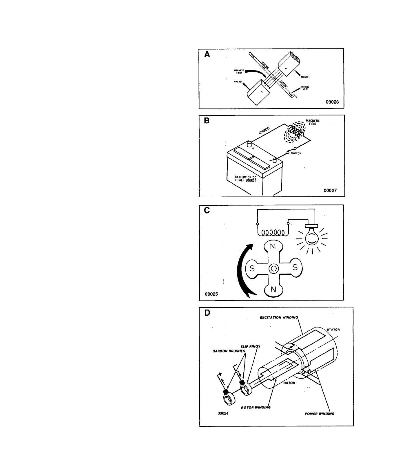
Electro-Magnetic Induction
A Magnetism Creates Electricity: - When a wire or
coii of wire is moved through a magnetic field, an electri
cal voltage is aeated in that wire. If the ends of the wire
are joined to complete a circuit, electrical current will flow
in the wire. The direction that current flows in the wire
depends on the polarity of the magnetic field.
B Current Flow Creates a Magnetic Field: - When
ever electrical current flows through a wire or coil of wire,
a magnetic field is created around that wire. The strength
of the field depends on the amount of current flow and
the number of coils or loops in the wire.
C A simple a-c generator consists of a spinning mag
netic field called a ROTOR and stationary coil of wire
called a STATOR. As the Rotor spins, its lines of mag
netic force cut across the stationary Stator. When the
ends of the Stator winding are connected across a load
(such as a light bulb) to complete the circuit, current will
flow through the circuit. In this simple generator, the
Rotor is a permanent magnet. The amount of voltage and
current flow induced into the Stator windings depends on
(a) the Rotor’s magnetic field strength, (b) Rotor rotational
speed, and (c) the number of turns of wire in the Stator.
A More Sophisticated a-c Generator
D A more sophisticated generator is equipped with a
Stator a-c power winding and a Stator excitation winding.
Regulated direct current from the excitation winding flows
through carbon brushes which slide on metallic slip rings
and then through the Rotor windings. Regulated current
flow through the Rotor creates a regulated magnetic field
strength. In turn, the regulated magnetic field strength
induces a regulated voltage into the stationary Stator;
winding. !
Page 5
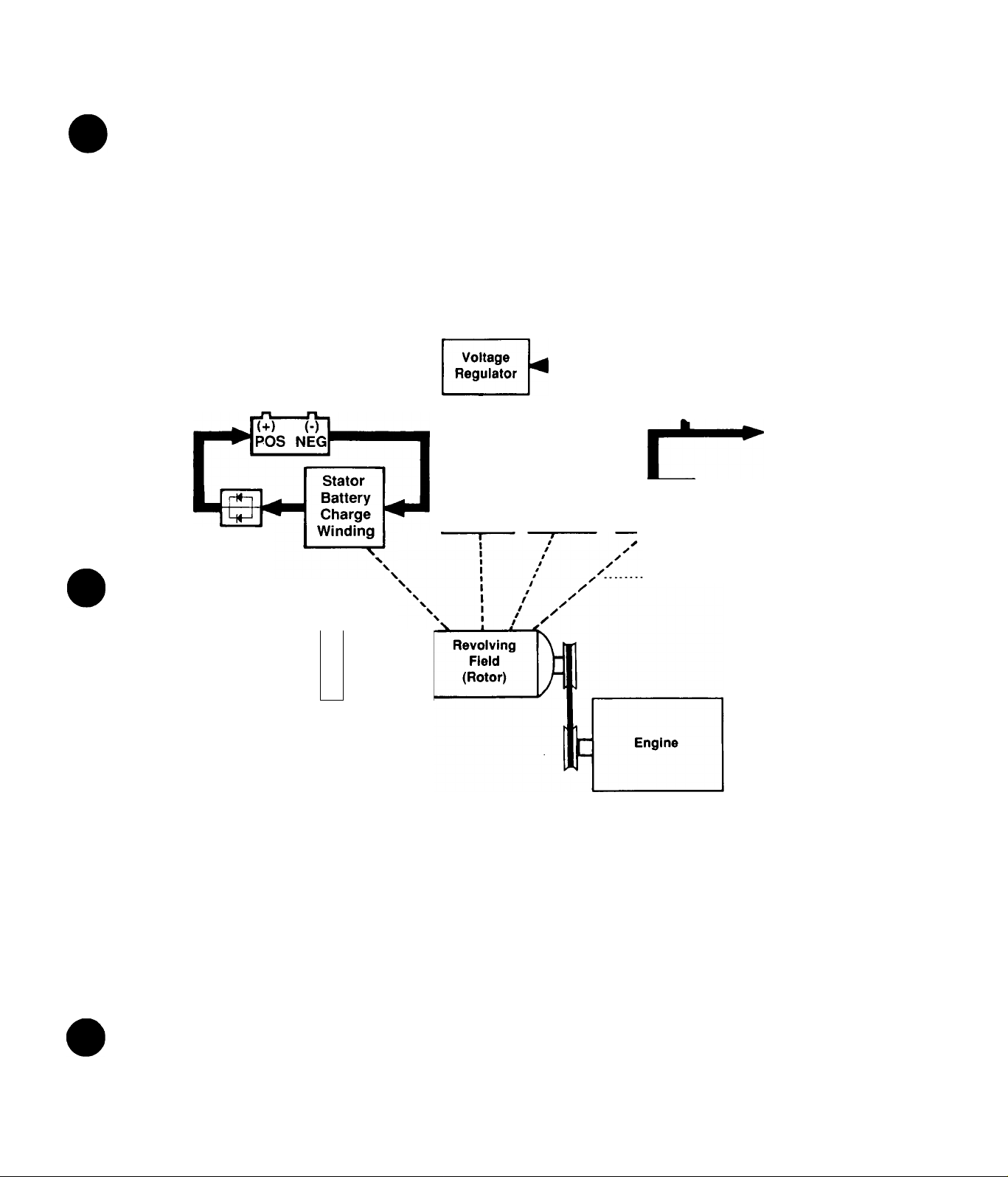
Generator Block Diagran^
E The Rotor (spinning fieid) is driven by the engine,
through a belt and pulley arrangement to maintain a fixed
operating speed. The Rotor’s magnetic field cuts across,
(a) a Stator a-c power winding, (b) a Stator excitation
winding, and (c) a Stator battery charge winding, to
induce a voltage Into those windings.
1. Stator Battery Charge Winding: Rectified direct
current output from this winding is delivered to the gen
erator’s 12-volts battery, to maintain battery state-ofcharge.
2. Stator a-c Power Winding:- The a-c output from this
winding is used to supply electrical power to connected
electrical loads.
3. Excitation Winding:- Output from this winding is
delivered to an Electronic Voltage Regulator, where it is
rectified and, based on a-c power winding sensing sig
nals, regulated. The regulated, rectified current flows
through the brushes and slip rings and into the Rotor
windings. Because the current flow is regulated, the
Rotor’s magnetic field strength Is regulated. In turn, be
cause the field strength is regulated, the voltage induced
into the Stator windings is regulated.
BATTERY
CHARGE
DIODE
00023
12 VOLTS
BATTERY
8
■T—f—L_r—\
Ü
Slip Rings \
Stator
Excitation
Winding
Stator a-c
Power
Winding
1
Stator a-c
Power
Winding
-r
Magnetic Field
Customer
Load
Connections
Page 6
INTRODUCTION TO TROUBLESHOOTING
Introduction
A typical RV generator set does not have a large number
of parts. However, the parts are expensive. For that
reason, a parts replacement method of troubleshooting is
not cost effective. A basic understanding of generators is
essential to good troubleshooting, i.e., why they behave
or don’t behave as they should. This section will introduce
the technician to some of the fundamentals of
troubleshooting.
DANGER!: Recreational vehicle generators produce
extremely high and dangerous voltages. Use ex
treme care when working on or around the gener
ator. Contact with live wires and terminals will cause
extremely hazardous and possibly lethal electrical
shock. Only personnel who have been thoroughly
trained In the maintenance of RV generators should
attempt to troubleshoot, test, repair or service a gen
erator.
Tools and Test Equipment
The generator service technician should have a well
stocked tool box having a good selection of common hand
tools. Such a tool box should contain wrenches in both
metric and english sizes. Also recommended is a good
nut driver set.
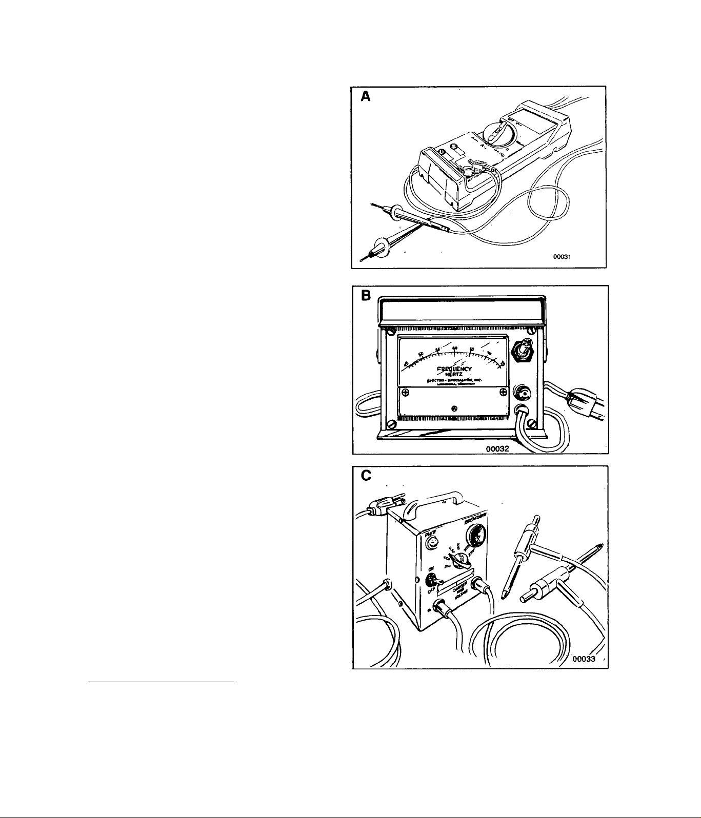
A Volt-Ohm-Milliammeter:-An accurate volt-ohm-mil-
liammeter (VOM) is essential for the troubleshooting and
testing of generators. Simply having a VOM is not
enough. The technician must understand electricity, must
be familiar with electrical circuits, must be able to read
wiring diagrams/electrical schematics, and must know
how tio use the VOM.
B Frequency Meter:- This test device permits the gen
erator’s a-c ou^ut frequency, in HERTZ or CYCLES PER
SECOND, to be read. Measurement of frequency is re
quired for precise adjustment of engine-generator speed.
Also see ROTOR ROTATIONAL SPEED.
C Insulation Resistance Tester:- Also called a "Hl-
POT", this device permits generator Stator and Rotor
winding insulation to be tested for breakdown. Use the
Hi-Pot tester to test resistance between parallel stator
windings, between isolated windings, and the resistance
of all windings to ground. See also EFFECTS OF DIRT
AND MOISTURE ON GENERATORS.
NOTE: An electrical LOAD BANK Is also recom
mended for generator testing and adjustment. The
Load Bank permits a known electrical load to be ap
plied to the generator, for the purpose of testing/adjustlng unit operation under load.
__________________
Rotor Rotational Speed
The generator’s revolving field on Series NP45G, NP55G
and NP65G generators is a 2-pole type, having a single
north and a single south magnetic pole. The Rotor is en
gine driven through a belt and pulley arrangenrient. Such
a 2-pole Rotor must be operated at 3600 rpm to supply
an a-c frequency output of 60 Hz. The belt and pulley ar
rangement pro>4des a speed reduction, so that engine
speed can be reduced while driving the Rotor at its re
quired operating speed. The following formulae apply
Page 7
when determining a-c frequency, Rotor rpm and number
of Rotor poles.
rpm X No. of Rotor Poles
Frequency = 2 x 60
2 X 60 X Frequency
RPM = No. of Rotor Poles
not be able to handle loads within the generator's rated
capacity. Problems with generator a-c output are oftencaused by an engine problem.
NOTE: A shorted condition In one or more con
nected electrical loads or In generator windings can
dramatically Increase the power demands on the
driving engine. Such shorted conditions may
present the same symptoms as an underpowered
engine.
________________________________________
2 X 60 X Frequency
Rotor Poles= rpm
Relationship of Voltage and Frequency
Engine governed speed and a-c voltage are adjusted with
no electrical loads applied to the generator (no-load).
That is, the a-c voltage is set at a fixed ratio to a-c
frequency. Recommended frequency and voltage set
tings are as follows:
Set Frequency to:
Set Voltage to;
*Llne-to-Neutral Voltage
60.5 to 63.5 Hz
121 to 127 volts*
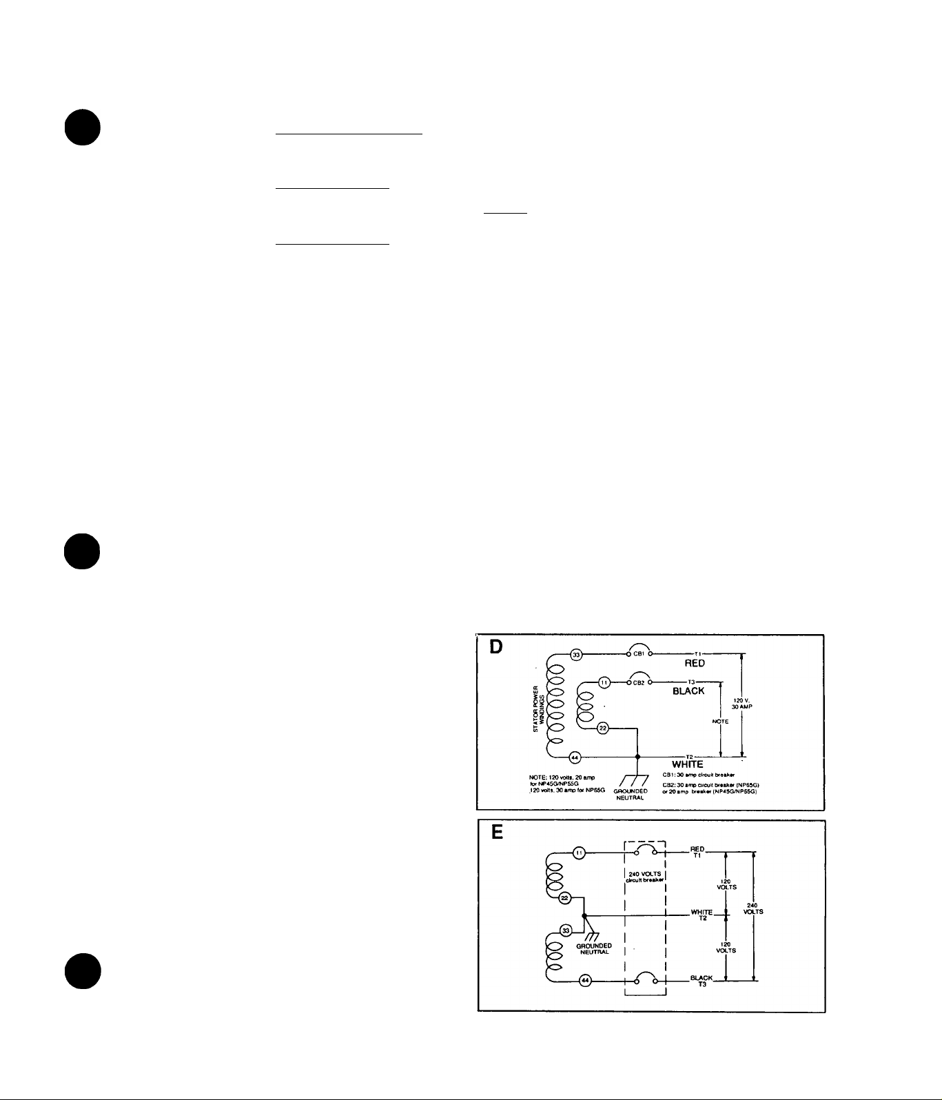
Generator a-c Connection System
D Series NP45G, NP55G and NP65G RV generators
are equipped with dual Stator a-c power windings. These
windings may be connected in parallel to provide a 120votts a-c output as shown. Note that customer loads of
up to 30 a-c amperes may be connected across Wires T1
(red) and T2 (white); loads up to 20 a-c amperes across
wires T2 (white) and T3 (black).
E The generator’s a-c output leads may be reconnected
in series, to supply a dual voltage (120 and/or 240 volts)
a-c output. When this is done, connect 240 volts a-c
loads across T1 (red) and T3 (black); 120 volts across T1
(red) and T2 (white) or T3 (black) and T2 (white). T2 is
the neutral wire.
Effects of Dirt and Moisture oh RV
Generators
If moisture is permitted to remain in contact with gener
ator windings, some of that moisture may be retained in
cracks and voids of the winding insulation. This will
cause a reduced insulation resistance. However,
prolonged exposure to moisture resistance of stator and
rotor winding Insulation. Dirt can make the problem
worse, since it tends to hold moisture into contact with
windings. Salt (as from sea air) also makes the problem
worse, since salt will absorb moisture from the air. When
salt and moisture combine, they form a good electrical
conductor.
Because of the detrimental effects of dirt and moisture,
the generator should be kept as clean and as dry as
possible. Stator and rotor windings should be tested
periodically, using an insulation resistance tester (Hi-Pot
or megohmmeterX If insulation resistance is excessively
low, drying may be required to remove moisture. After
drying, a second test of insulation resistance is still low
after drying, replacement of defective windings may be
necessary.
Effects of Engine Power
The generator engine must develop sufficient power to
operate the generator under varying electrical loads. The
greater the wattage (amperage) demands ot connected
electrical loads, the greater the engine power needs. As
a general rule, approximately 2 engine horsepower is
ne^led for each 1000 watts (1.0 kW) of generator power
output.
If the generator’s wattage/amperage capacity is ex
ceeded, engine power may not be adequate to handle
the increased load. The result will be a decrease in
engine rpm, a corresponding decrease In generator a-c
output voltage and frequency, and internal generator
overheating.
A badly worn engine, one that has lost compression, or
one with defective fuel. Ignition or air Intake system may
Page 8
OPERATIONAL ANALYSIS OF D-C CONTROL SYSTEM
Introduction
This section of your Manual is intended to familiarize the
reader with how the RV generator’s d-c control system
functions. The d-c control system provides the means to
obtain engine cranking, engine ignition and fuel flow, car
buretor choking, field boost and battery charging. If
problems with any of these functions are encountered,
the technician must have a working knowledge of how the
system operates.
Circuit Condition- Engine Shut Down
A With engine stopped, the circuit condition may be
described as follows:
1. Battery voltage is available to the normally-open
Starter Contactor (SC) contacts. The contacts are open
and the circuit is incomplete.
2. Battery voltage is available through a 15 amp Fuse (FI)
and to the normally open contacts of Control Relay (CR1).
These contacts are open and the circuit is incomplete.
3. Battery voltagte is available through Fuse (Ft), through
the normally-closed contacts of Control Relay (CR1),
through the Starter Contactor (SC) coil, and to the
Start/Stop Switch (SW1). However, the Switch contacts
are open and the circuit is incomplete.
4. Battery voltage is available through Fuse (F1), through
the Control Relay (CR2) actuating coil, and to the
Start/Stop Switch (SW1). However, the Switch contacts
are open and the circuit is incomplete.
5. Battery voltage is available to the Battery Charge Rec
tifier (BCR), via Wire #13, 15 amp Fuse (FI), Wire #15,
and to a Battery Charge Rectifier (BCR). However, BCR
diode action inhibits Current flow.
Circuit Condition- Engine Cranking
B When the Start/Stop Switch is held at its START posi
tion, the following sequence of events occurs
1. Start/Stop Switch closure connects the Control Relay
(CR2) and the Starter Contactor (SC) actuating coils to
frame ground.
2. The Starter Contactor (SC) energizes and its contacts
close to deliver battery voltage to (a) Starter Motor (SM)
and (b) a Choke Solenoid (CS) and (c) a Choke Module
(CM). The following events then occur:
a. Starter Motor (SM) energizes and the engine
cranks.
b. Battery voltage is delivered to the Choke Module
(CM), via Wire 16, the Choke Solenoid coil, and Wire
90. Choke Module (CM) action opens and closes
this circuit to ground at a rate dependent on ambient
temperature, to energize and de-energize the Choke
. Solenoid. Choke Solenoid (CS) opens and closes
the carburetor choke.
c. Battery voltage delivered to the Choke Module
(CM) is delivered to the generator Rotor windings via
a Field Boost Resistor and Diode (housed in the
Choke Module), Wire 4 and the Rotor brushes and
slip rings. This is field boost.
"1
-
7 ^
>-
&
►-
■t° Ife
-gAAAn
&
LEGEND
BCRc
. BATTERY CHARGE RECTIFIER
CIRCUIT BREAKER- 30 AMP
CB1 a
CIRCUIT BREAKER
CB2a
CH -
. CHOKE HEATER
CM c
.CHOKE MODULE
I CONTROL RELAY
CR1 -
. CONTROL RELAY
CR2-
. CHOKE SOLENOID
CS -
FI a
FUSE- 15 amp
FP -
FUEL PUMP
GROUND TERMINAL
QT HM c
. HOURMETER (Optional)
IGNITION MAGNETO
IMI IM2.
IGNITION MAGNETO
K3NmON SHUTDOWN
ISD.
RUN LIGHT
LI -
. LOW OIL PRESSURE, SWITCH
. LOP-
RESISTOR-1 ohm, 25 watt
R1 -
SC - STARTER CONTACTOR
SM - STARTER MOTOR
SW1 - START/STOP SWITCH
SPI - No. 1 SPARK PLUG
SP2 - No. 2 SPARK PLUG
TC o TERMINAL CONNECTOR
- WIRE NUT CONNECTION
Page 9
d. Battery voltage is delivered through a diode
(housed in the Choke Module) and to the Wire 14 cir
cuit. Wire 14 is now electrically hot, to operate (a) a
Fuel Pump (FP), (b) a Choke Heater (CH), and (c)
an "Engine Run" lamp on the optional remote panel.
3. Control Relay (CR2) energizes, its nonnaiiy-closed
contacts open and the Wire 18 circuit is effectiveiy iso
lated from frame ground. Ignition can now occur, since
that circuit Is now open to ground.
4. With automatic choking, and with fuel flow and ignition
available, the engine will start.
5. Engine oli pressure buildup opens the Low Oil Pres
sure Swritch (LOP).
Circuit Condition- Startup and Running
C When engine fires and starts, the operator will release
the Start/Stop Switch. Circuit condition may then be
described as follows:
1. When a-c output from the generator's Battery Charge
Winding reaches approximately 9-12 volts a-c. Control
Relay (CR1) energizes and its normally open contacts
close, to deliver battery voltage to the Wire 14 circuit (Fuel
Pump and Choke Heater actions continue).
2. The Starter Contactor (SC) and Control Relay (CR2)
circuits to ground are opened.
Page 10
3. Starter Contactor (SC) de-energizes and its contacts
open to effect the following
a. Starter Motor (SM) de-enerizes and cranking
ends.
b. Carburetor choking terminates.
c. Field Boost ends.
d. Power to the Wire 14 circuit through the Choke
Module ends.
4. Control Relay (CR2) de-energizes and its normallyclosed contacts close. However, the ignition circuit to
ground is held open by Low Oil Pressure Switch (LOP)
action and engine ignition continues.
5. Stator Battery Charge Winding (rectified) output is
delivered to the generator battery.
Circuit Condition- Normal Shutdown
D Closure of the Start/Stop Switch (SW1) to its STOP
position grounds the engine ignition circuit, ignition ter
minates and the engine shuts down. As engine speed
decreases. Low Oil Pressure Switch (LOP) closure main
tains the ignition ground condition.
Page 11
r
INSULATION RESISTANCE TESTS
General
Refer to EFFECTS OF DIRT AND MOISTURE ON RV
GENERATORS (Page 5). The resistance of rotor and
stator windings should be tested periodically, using a
"Hi-Pot" resistance tester.
CAUTION!: When using the Hl-Pot (Insulation Resis
tance) tester, follow the tester manufacturer’s In
structions carefully. Improper use of the tester can
result in serious damage to the generator. Do not
apply voltage in excess to those recommended in
this Manual to Stator or Rotor windings.
____________
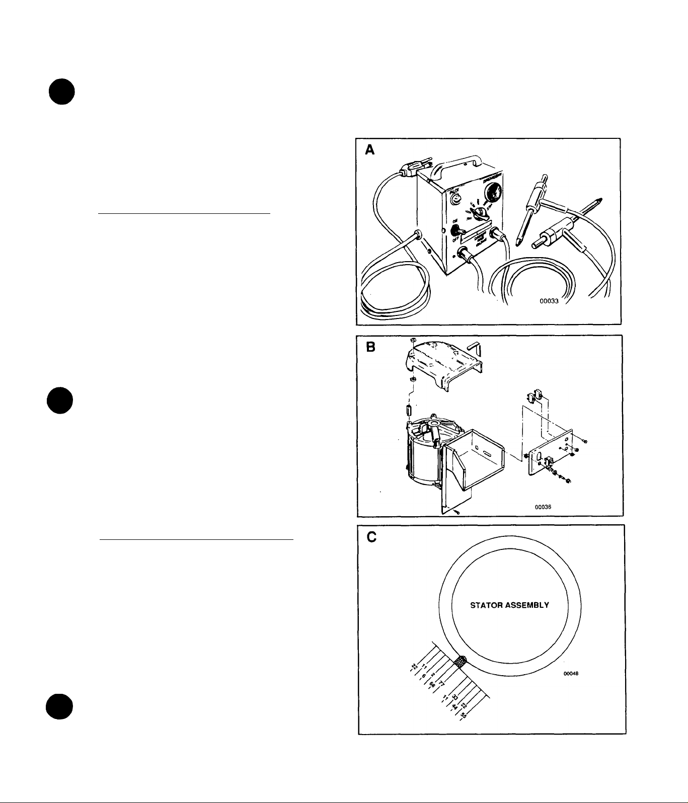
The Hi-Pot Tester
A The Hi-Pot tester shown is oniy one of many brands
available. It is equipped with an On/Off switch. Thepiiot
Lamp glows to indicate tester power is availabie. The
breakdown tamp will light to Indicate failure of the winding
being tested.
Testing Stator insuiation
6 Gain Access to Stator Leads: Remove screws that
retain the front panel to the panel housing. Remove the
generator cover. Inside the panel housing, locate the
Electronic Voltage Regulator and the 30-amp Circuit
Breaker (CB1).
4. Tum tester switch ON and check that Pilot Lamp is ON.
Then, set Voltage Selector Switch to 2000 volts. Observe
the BREAKDOWN lamp, wait one second, then turn
tester switch OFF.
C Disconnect Stator Leads: Disconnect Stator a-c
output wires 11 and 22 from the Electronic Voltage
Regulator terminals. Disconnect Stator Wire 33 from the
30-amp Breaker (CB1). Separate wires 22 and 44 at their
junction. Finally, disconnect Stator Excitation Wiriding
Wires 2 and 6 from the Electronic Voltage Regulator
terminals.
DANGER!: Follow the Instructions carefully. Wire
terminal ends must not be touching any part of the
generator when Hl-Pot voltage Is applied. Do not
exceed the recommended voltages. Apply voltage
to windings for a maximum of 1 second only.
Test All Stator Windings to Ground: Connect terminal
ends of Stator a-c output Wires 11, 22, 33, 44, 2 and 6
tightly together. Make sure no terminal end is in contact
with the generator frame. Then proceed as follows:
1 .Connect RED test lead of Hi-Pot tester to joined ter
minal ends of Wires 11,22, 33, 44, 2 and 6.
2. Connect the BLACK test lead to a dean, painted frame
ground (on generator Stator can).
3. Turn Hi-Pot tester switch OFF. Then plug tester into a
120 voits wall socket and set its Voltage Selector Switch
to 500 volts.
CAUTION!: IN STEP 4, DO NOT APPLY VOLTAGE
LONGER THAN ONE MINUTE.
Page 12

Test Between Isolated Windings:- To test between iso
lated Stator windings, proceed as follows:
1. Connect RED lead of Hi-Pot tester to terminal end of
Wire 11, BLACK test lead to Wire 2 terminal end.
2. Turn tester switch ON and check that Pilot Light is ON.
3. Set Voltage Selector Switch to 1500 voits- APPLY
VOLTAGE FOR ONE SECOND ONLY. Observe tester
Breakdown lamp. Turn tester switch OFF and reset Vol
tage Selector Switch to 500 volts.
Test Between Parallel Windings:- Test between paral
lel Stator windings as follows:
1. Set tester Voltage Selector Switch to 500 volts.
2. Connect tester RED test lead to Wire #11, BLACK test
lead to Wire 33.
3. Turn tester switch ON and check that Pilot Light is ON.
4. Apply voltage for one second while observing the
Breakdown lamp. Then, turn tester switch OFF.
RESULTS: If tester Breakdown lamp comes ON
during any one second test, clean and dry the stator.
Then, repeat the breakdown test. If Breakdown lamp
Illuminates after drying, replace the Stator Assemb
ly-
Testing Rotor Insulation for Breakdown
D Remove generator cover to gain access to the Rotor
slip rings and brushes. ,
E Remove all wires that connect to the Brushes. Then,
test Rotor insulation as follows:
1. Connect tester RED test lead to the positive {+) Rotor
slip ring (nearest the Rotor bearing).
2. Connect BLACK test lead to a clean frame ground.
3. Turn tester switch OFF.
4. Plug tester into a 120 volts wall socket.
5. Set Voltage Selector Switch on tester to 500 volts.
6. Turn tester switch ON and check that Pilot Light is ON.
7. Set Voltage Selector Switch to 1250 volts and observe
the tester breakdown lamp. Then, turn tester switch OFF.
RESULTS:- If tester breakdown lamp lllumlates
during the 1 second test, drying of the generator may
be necessary. After drying, repeat the Hl-Pot test. If
Rotor windings fall the second test (after drying),
replace the Rotor assembly.
Cleaning the Generator
Removed caked on or greasy dirt with a soft brush or a
clean, damp doth. A vacuum system may be used to pick
up loosened dirt. Loose dust and dirt may also be
removed using low pressure, dried air (25 psi maximum).
CAUTION!: Do NOT use a forceful spray of water to
clean generator. Some of the water will be retained
on generator windings and will cause serious
problems.______________________________________
Drying the Generator
1. Open the main drcuit breaker or main line switch. NO
ELECTRICAL LOADS MUST BE CONNECTED TO
GENERATOR WHILE DRYING.
2. Remove the generator cover (see illustration "B" on
previous page).
3. Disconnect Wire #4 from the Electronic Voltage
Regulator.
4. Provide an external source to blow warm, dry air
through the generator. Do NOT exceed 185' F. (85* C.).
5. Start the engine, let it run for 2 to 3 hours.
6. Stop the engine and retest Stator and Rotor windings.
10
Page 13

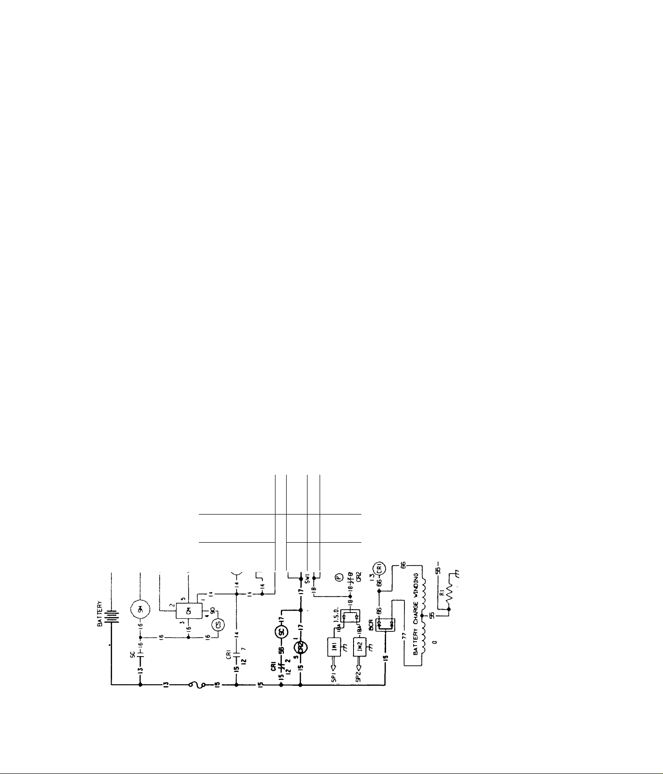
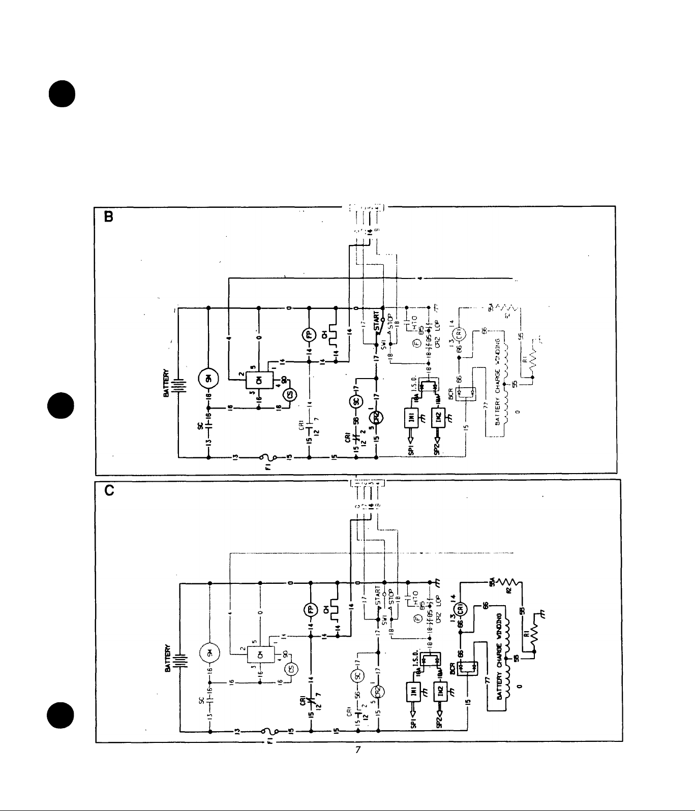
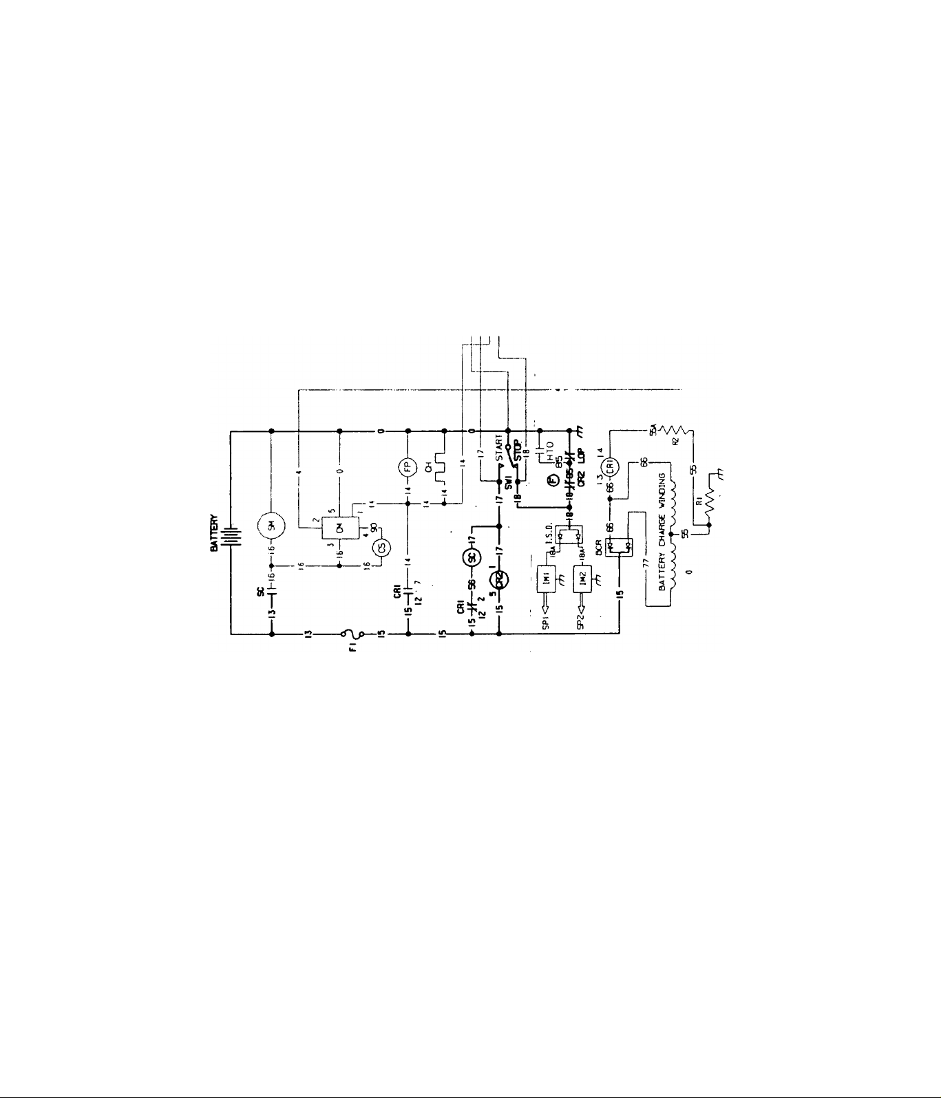
WIRING DIAGRAM & ELECTRICAL SCHEMATIC
11
Page 14

TROUBLESHOOTING THE RV GENERATOR
Introduction
The service technician can use this troubieshooting guide
to determine the cause of existing problems. Six common
problems are covered in this section. Problems are not
arranged in any particuiar sequence.
The first step in troubleshooting is to identify your par
ticular problem. When you have identified your problem,
locate that problem in the troubleshooting guide on this
page. When working your way through the step-by-step
procedure for that problem, start at Step 1 and follow
through the step-by-step procedure. Each step is ar
ranged in a definite sequence, from the more probabie/easiest to check to the less probable/more complex
to check. When the cause of the problem is found and
corrected, stop the test.
Follow the step-by-step procedures carefully. After com
pleting each test, read the TEST RESULTS. Some test
resuits may instruct you to skip certan steps and proceed
to a new step number.
Problem No. 1- Engine Won’t Crank
Step 1- Check 15 amp Fuse FI
Step 2- Check Battery
Step 3- Check Starter Contactor SC
Step 4- Check Starter Motor SM
Step 5- Check Start/Stop Switch SW1
Step 6- Check Control Relay CR1
Problem No. 2- Engine Cranks, Won’t Start
step 1- Check Fuel Quantity
Step 2- Check Fuel Shutoff Valves
Step 3- Check Fuel Flow
Step 4- Check Fuel Filter
Step 5- Check Fuel Pump
Step 6- Check Engine Ignition System
Step 7- Test Choke Module
Step 8- Check Automatic Choke Operation
Step 9- Check Engine Compression/Condition
Step 10- Test Control Relay CR2
Problem No. 3- Engine Cranks and Starts,
Shuts Down When Start/Stop Switch is
Released
Step 1 - Check Engine Oil Level
Step 2- Check Oil Pressure Switch
Step 3- Check Control Relay CR1
Step 4- Check Stator Battery Charge Windings
Step 5- Check Resistor R1
Problem No. 4- Engine Starts Hard, Runs
Rough
Step 1- Check Engine Ignition System
Step 2- Check Carburetion
Step 3- Check Engine Compression
Step 4- Test Automatic Choke
Problem No. 5- Engine Won’t Shut Down
Step 1 - Check Start/Stop Switch
Step 2- Check Wire #18 & #0
Step 3- Check Engine Ignition System (I.S.D.)
Problem No. 6- Loss of Generator a-c Out
put
Step 1- Check Circuit Breakers CB1/CB2
Step 2- Check Vehicle Wiring
Step 3- Check a-c Voltage and Frequency
Step 4- Check Load Voltage and Frequency
Step 5- Check/Adjust Engine Governor
Step 6- Check Field Boost Circuit
Step 7- Check Stator Excitation Windings
Step 8- Check Stator a-c Power Windings
Step 9- Check Rotor (Field) Circuit
Step 10- Check Voltage Regulator Sensing
Step 11- Check/Adjust Voltage Regulator
12
Page 15

TROUBLESHOOTING GUIDELINES
Problem No. 1- Engine Won’t Crank
step 1- Check 15 amp Fuse F1
Test Procedure: Remove Fuse FI from generator panel
and Inspect fuse element. If necessary, use a Volt-Ohm-
Mllllammeter (VOM) to check fuse for continuity.
Test Results:A. Fuse FI checks GOOD: Go to Step 2
B. Fuse FI Is open: Replace Fuse FI. If engine cranks
normally STOP.
Step 2- Check Battery
Test Procedure:- Perform the following checks/tests on
the generator battery:
1. Inspect battery terminals (posts) and cables. Cable
clamps and connections must be clean and tight. Glean
and/or tighten cable clamps and connections as neces
sary. Replace any defective cables.
2. Use an automotive type battery hydrometer to test bat
tery STATE OF CHARGE. Follow the hydrometer
manufacturer’s instructions carefully. Write down the
specific gravity of the electrolyte fluid in each battery cell.
Write down the specific gravity reading of each cell as the
reading is taken. Return the electrolyte fluid to the cell
from which it was removed. If the hydrometer used does
not have a percentage of charge scale, compare the read
ings obtained with the following:
SPECIFIC GRAVITY PERCENT OF CHARGE
1.260
1.230
1.200
1.170
If necessary, use an automotive type battery charger to
recharge the battery to a 100% state of charge.
100%
75%
50%
25%
Step 3- Check Starter Contactor SC
Test Procedure:- Starter Contactor operation may be
tested as follows:
1. See Figure 1. Connect the positive (+) test lead of a d-
c voltmeter to the Wire 56 terminal of the Starter Contac
tor. Connect the meter negative (-) test lead to a clean
frame ground. The voltmeter should indicate battery vent
age (12 volts d-c).
Test Results:
A. Battery voltage NOT indicated: Go to Step 6
B. Battery voltage was indicated: Continue test
2. Connect the positive (+) test lead of a d-c voltmeter to
the Wire 16 terminal stud of the Starter Contactor; con
nect negative (-) test lead to a dean frame ground. Zero
volts should be indicated.
3. With d-c voltmeter still connected to the Wire 16 ter
minal stud and frame ground, disconnect Wire 17 from its
terminal stud on Starter Contactor. Connect a jumper wire
from the Wire 17 terminal stud (on Starter Contactor) to
a clean frame ground. The d-c voltmeter should indicate
battery voltage and engine should crank.
Test Results:
A. Battery voltage GOOD and engine cranks, but will not
crank with Start/Stop Switch: Go to Step 5
B. Battery voltage GOOD, engine does NOT crank: Go
to Step 4
C. Zero battery voltage with jumper wire connected and
engine does not crank; Replace Starter Contactor SC.
DANGER!: Storage batteries give off EXPLOSIVE
hydrogen gas while charging. Completely remove
the battery from the vehicle before attempting to
recharge It. Charge the battery only In a well venti
lated space where explosive gases cannot accumu
late and present the danger of explosion. Do not per
mit smoking, open flame or sparks in the vicinity
while charging a battery.
3. If the difference in specific gravity between the highest
and lowest reading cell is 0.050 (50 points) or greater, the
battery is nearing the end of its usefui life and should be
replaced. However, if the lowest reading cell has a
specific gravity of less than 1.200, recharge the battery
and then repeat the specific gravity test. If, after charg
ing, the difference between the highest and lowest read
ing cell is still 0.050 (50 points), replace the battery.
Test Results:A. Normal engine cranking occurs: STOP tests
B. Battery checks GOOD, no cranking; Go to Step 3.
_________________________
Step 4- Check Starter Motor SM
Test Procedure:- Connect a jumper cable to the large
battery cable terminal stud (Wire 13) of the Starter Con
13
Page 16

tactor and to the cable terminal on Starter Motor. Engine
should crank.
Test Results:
A. Engine cranks normally but does not crank when using
the Start/Stop Switch: Go to Step 5.
B. Engine does NOT crank: Replace Starter Motor SM
C. Engine cranks normally with jumper cable and with
Start/Stop Switch: STOP tests.
2. Connect a jumper wire between the Start/Stop Switch
Wire 17 terminal and a clean frame ground connection.
Engine should crank and start. Disconnect jumper wire to
terminate cranking when engine starts. To stop the en
gine, connect jumper wire to Wire 18 terminal of
Start/Stop Switch and to frame ground.
Test Results:
A. Engine cranks, starts and shuts down normally when
using jumper wire, but not when using Start/Stop Switch:
Replace Start/Stop Switch.
B. Engine will not crank when using jumper wire: Go to
Step 6.
C. Engine cranks and stops normally when using jumper
wire and with Start/Stop Switch: STOP tests.
Step 6- Check Control Relay CR1
NOTE: See WIRING DIAGRAM & ELECTRICAL
SCHEMATIC on Page 11. Two different types of Con
trol Relay CR1 are used on the NP series generators,
Identified In the Wiring Diagram as "CRI" and "AlternateCRl". Also see Figures 4 and 5
NOTE: For Starter Motor SM testing and repair In-
Structlons, refer to ENGINE SERVICE MANUAL.
Step 5- Check Start/Stop Switch SW1
Test Procedure:- See Figure 3. Test the Start/Stop
Switch as follows:
1, Set a Volt-Ohm-Milliammeter (VOM) to its "Rxl" scale
and zero the meter. Connect one VOM test lead to the
Wire 0 terminal of Start/Stop Switch; connect second
meter test lead to a clean frame ground. The VOM should
indicate continuity.
Test Results:
A. VOM does NOT indicate continuity: Repair or replace
Wire 0 between Switch and frame ground connection, as
necessary.
B. VOM indicates continuity: Continue test.
Test Procedure:- See Figure 4 or 5. Test the Relay as fol
lows:
1. Connect the positive (+) test lead of a d-c voltmeter to
CRI terminal 12 (Wire 15 terminal): connect the negative
(-) test lead to a clean frame ground. Meter should indi
cate battery voltage. If alternate CRI is installed, connect
meter positive (+) test lead to Relay terminal 9 (Wire 15
terminal).
Test Results:
A. Battery voltage is indicated; Continue test
B. Battery voltage is NOT indicated:- Repeat Step 1. Also
check Wire 15 between Relay CRI and Fuse FI for open
or disconnected condition; Wire 13 between Fuse FI and
Starter Contactor SC for open; and positive (+) battery
cable to Starter Contactor SC.
2. Connect the positive (+) test lead of a d-c voltmeter to
CRI terminal 2 (Wire 56 terminal); negative (-) test lead
to frame ground. If alternate CRI is installed, connect
meter positive (+) test lead to Relay terminal 3 (Wire 56
terminal). Battery voltage should be indicated.
Test Results:
A. Battery voltage NOT indicated: Replace Control Relay
CRI
B. Battery voltage was indicated: Repeat Steps 1 through
5. Refer to WIRING DIAGRAM (Page 11) and test wires
for open or shorted condition.
14
Page 17

Figure 4. Control Relay CR1
3D
n
56 15 I 55A
_U
12 14
7 P rO
14 66
___
I I 1_
4]
13
00047
Test Results:
A. Fuel Shutoff Valve(s) are closed: Open all valves
B. Shutoff valves are open, engine wili not start: Go to
Step 3
Step 3- Check Fuel Flow (Gasoline System Only)
Test Procedure:- Disconnect fuel line at engine car
buretor inlet. Crank engine and check fuel flow from open
end of disconnected line.
Test Results:
A. Fuel Flow is inadequate: Go to Step 4
B. Fuel flow checks GOOD: Go to Step 6
Step 4- Check Fuei Filter (Gasoline System Only)
Test Procedure:- See Figure 6. if fuel flow to carburetor
is low, try a new fuel filter. Make sure arrow on filter body
points in direction of flow toward carburetor. With new fil
ter installed, recheck fuel flow as outlined in Step 3.
Test Results:
A. Fuel flow is normal: STOP tests
B. Fuel flow still inadequate: Go to Step 5
Problem No. 2 - Engine Cranks, Won’t Start
step 1 - Check Fuel Quantity
Test Procedure: When troubleshooting a problem, the
most simple causes are often overlooked. If engine
cranks normally but won’t start, check that adequate
supply of the proper fuel is available. Many RV generator
Installations with shared fuel tank utilize a generator fuel
pickup tube thatis shorter than the vehicle engine's fuel
pickup tube. For that reason, the generator will "run out
of gas" while fuel is still available for the vehicle engine.
Test Results:
A. Fuel quantity is adequate: Go to Step 2.
B. Inadequate fuel in tank: Fili fuei tank.
Step 2 - Check Fuel Shutoff Valves
Test Procedure: The fuel supply line in the vehicie may
be equipped with one or more fuei shutoff valves. If
engine will not start, check that all fuel supply valves are
open.
Step 5- Check Fuel Pump (Gasoline System Only)
Test Procedure:- Locate the 4-tab terminal connector to
which Wires 14 connects. Locate Wire 14 from Fuel Pump
on the terminal connector. Connect the positive (+) test
lead of a d-c voltmeter to the Fuel Pump’s Wire 14 ter
minal; connect negative (-) test lead to a clean frame
ground. Crank engine- the voltmeter should indicate bat
tery voltage and the Fuel Pump should operate.
Test Results:
A. Battery voltage is indicated and Fuel Pump operates,
but still no start: Go to Step 6
B. No battery voltage indicated and Fuel Pump does not
operate: Go to Step 7
15
Page 18

Step 6- Check Engine Ignition System
Test Procedure:- Refer to section in this Manual entitled
ENGINE TROUBLESHOOTING. Also refer to the EN
GINE SERVICE MANUAL, if necessary.
Test Results:
A. Ignition System checks GOOD: Go to Step 7
B. Ignition System checks BAD: Repair or replace defec
tive component(s) mas necessary
Figure 7. Choke Module
© o
©L3
Step 7- Test Choke Module
NOTE: The following procedure will test the Wire 14
diode, the field boost diode, and the field boost
resistor. To test these components. It Is recom
mendecf that a Volt-Ohm-Mllllammeter having a
DIODE TEST capability be used. The solid state cir
cuit that regulates automatic choke opening and
closing cannot be tested In the field. That circuit will
be tested In Step 8 by observing choke operation,
Test Procedure:- See Figure 7. Disconnect ail wires from
Choke Moduie terminals to prevent interaction. Then,
proceed as follows:
1. To test the Wire 14 diode, connect one VOM test lead
to Terminal 3 of the Choke Module; connect second test
lead to ,Terminal 1. Observe the meter reading. Then,
reverse the test leads (reverse the d-c polarity) across
those Choke Module terminals and again observe the
reading. At one polarity, the VOM should read infinity. At
the opposite polarity, the VOM should indicate the for
ward resistance of the 6 amp, 100 volts diode in the Wire
14 circuit. If using a VOM having the diode test feature,
allowable voltage drop across the diode is 0.6 to 0.8 volt.
2. To test the Field Boost diode and resistor, connect one
VOM test lead to Choke Module Terminal 3, the second
test lead to Terminal 2. Note the meter reading. Then,
reverse the test leads (reverse polarity) and again ob
serve the VOM reading. At one polarity, the meter should
indicate infinity. At the opposite polarity, the meter should
read the forward resistance of the diode plus the resis
tance of the Field Boost Resistor. If a VOM having the
diode test feature is used, allowable voltage drop will be
0.6 to 0.8 volts PLUS the voltage drop across the resis
tor.
f
00043
Step 8- Check Automatic Choke Operation
Test Procedure;- See Figure 8. Crank engine while ob
serving choke operation. The Choke Solenoid CS should
pull in to close choke for about 0.2-0.4 seconds, should
then de-energize to open choke for about 2 seconds. This
cyclic action should occur while the engine is cranking. If
Choke Solenoid does not actuate, check for binding. Also
check for proper choke adjustment (see ADJUSTMENTS
section).
Test Results:
A. Choke operation checks GOOD, engine still won’t
start: Go to Step 9
B. Choke operation checks BAD: Try adjusting choke- if
it still does not operate, replace Choke Module
NOTE: The Field Boost Resistor is rated 47 ohms at
2 watts (plus or minus 10%). The Field Boost diode
Is rated 1 amp at 600 volts.
3. The Choke Module circuit includes a metal oxide Varis
tor, rated 22 volts, 0.6-0.8 Joule. There is no good method
of testing a Varistor in the field. Typically, when a Varis
tor fails it will overheat and melt. Inspect the Choke
Module- if evidence of overheating and melting is ob
served, replace the Choke Module.
Test Results:
A. All Choke Module tests are GOOD: Go to Step 8
B. Choke Moudle tests BAD: Replace Choke Module
_________________________
Step 9- Check Engine Compresslon/Condition
Test Procedure:- Refer to section entitled ENGINE
TROUBLESHOOTING. If necessary, also refer to the EN
GINE SERVICE MANUAL.
Test Results:
A. Engine^Checks GOOD: Go to Step 10
B. Engine checks BAD; Repair/replace engine as neces
sary
16
Page 19
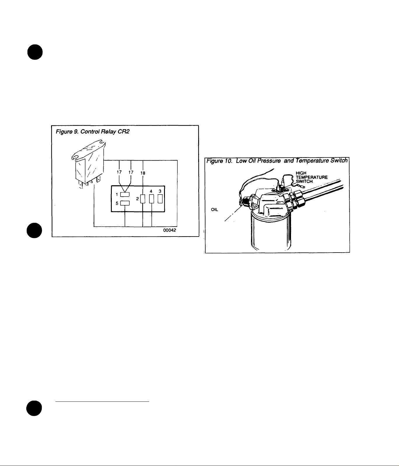
step 10- Test Control Relay CR2
Test Procedure:- See Figure 9. Disconnect Wire 18 from
Reiay Terminai 2 and Wire 85 from Terminai 4, to prevent
interaction. Set a VOM to its "Rxl" scaie and zero the
meter. Then, connect the VOM test ieads aaoss Reiay
Terminais 2 and 4- the meter needie shouid swing ups-
caie (continuity). Hoid Start/Stop Switch at START to
crank engine- the VOM needie shouid drop aii the way
downscaie (infinity).
Test Results:
A. Control Relay CR2 checks GOOD; Repeat Steps 1
through 9
B. Control Relay CR2 checks BAD: Replace Relay CR2
Step 2 - Check Oil Pressure Switch
Test Procedure: Set a VOM to its "Rxl" scale and zero
the meter. Disconnect Wire 85 from the Switch terminal,
then test the Low Oil Pressure Switch (Fig. 10) as follows:
1. Connect one VOM test lead to the switch terminal, the
remaining test lead to a clean frame ground. Meter
should indicate continuity.
2. Crank engine. The VOM needle should drop all the
way downscale (infinity) as oil pressure inaeases.
3. If the engine starts and runs, hold terminal end of Wire
85 into firm contact with a dean frame ground. Engine
should shut down.
Test Results:
A. Oil Pressure Switch checks GOOD: Go to Step 3.
B. Oil Pressure Switch checks BAD: Replace switch.
Problem No. 3- Engine Cranks and Starts,
Shuts Down When Start/Stop Switch is
Released
Step 1- Check Engine Oil Level
Test Procedure:- Check engine oil level as outlined in
Owner’s Manual. If oil level is low, sufficient oil pressure
to open the Low Oil Pressure Switch contacts will not be
developed. With Start/Stop Switch at START, Control
Relay CR2 action will open the engine ignition circuit to
ground. However, as soon as the Start/Stop Switch is
released, CR2 contacts will close and closure of the Low
Oil Pressure Switch contacts will close the ignition circuit
to ground and ignition will terminate. The result will be an
ehgine'shutdown as soon as the Start/Stop Switch is
released.
Test Results:-
A. Oil level is LOW: Add oil as required (don’t forget Oil
Makeup Tank)
B. Oil level is GOOD: Go to Step 2
NOTE: You may wish to check engine oil pressure.
See ENGINE SERVICE MANUAL for Oil pressure
check procedures and specifications.
______________
Step 3- Check Oil Temperature Switch
Test Procedure: Set a VOM to its "Rxl" scale and zero
the meter. Disconnect Wire 85 from the Switch terminal,
then test the Oil Temperature Switch (Fig. 10) as follows:
1. Connect one VOM test lead to the switch terminal, the
remaining test lead to a clean frame ground. Meter
should indicate continuity.
2. If the engine starts and runs, hold terminal end of Wire
85 into firm contact with a dean frame ground. Engine
shouid shut down.
Test Results:
A. OifTemperature Switch contacts check GOOD: Go to
Step 4.
B. Oil Temperature Switch contacts check BAD: Check
wiring.
17
Page 20

Step 4 - Check Control Relay CR1
Test Procedure: Refer to Step 6 under Problem No. 1.
Test Results:
A. Control Relay CR1 checks GOOD: Go to Step 5.
tion. Set a VOM to Ks "Rxl" scale and zero the meter.
Connect the first meter test probe to the Wire 55 terminal
of Resistor. Connect second test probe to a clean frame
ground. Meter should indicate about 1 ohm (plus or minus
5%).
B. Control Relay CR1 checks BAD: Replace Control
Relay CR1.
Step 5 - Check Stator Battery Charge Windings
NOTE: The Volt-Ohm-Mllllammeter (VOM) used to
test Stator windings must be accurate. Recommended Is a digital meter of high accuracy.
Test Procedure: Disconnect Wires 66 and 77 (Fig. 11)
from the Battery Charge Rectifier BCR terminais. Set a
VOM to its "Rxl" scaie and zero the meter. Connect the
meter test ieads across the terminal ends of Wires 66 and
77, just removed from Battery Charge Rectifier BCR. The
VOM should indicate Stator Battery Charge Winding
resistance, as follows:
Series NP45G = 0.12 ohm
Series NP55G = 0.09 Ohm
Series NP65G = 0.07 ohm
All test readings are plus or minus 10%.
Now, set the VOM to its "Rxl 0,000" scale and zero the
meter. Connect one VOM test lead to terminal end of
Wire 66, remaining test lead to a dean frame ground. No
upscale movement of the meter should be noted (infinity).
Test Results:
__________
Test Results:
A. Resistor R1 checks GOOD: Repeat Steps 1 through 4
under Problem No. 3.
B. Resistor R1 checks BAD: Replace Resistor R1.
Figure 12. Resistor R1
X BATTERY CHARGE
7 WINDING
-T
55
00053
R1
66
rh GROUND
Problem No. 4 - Engine Starts Hard, Runs
Rough
Step 1 - Check Engine Ignition System
A. Battery Charge Winding checks GOOD: Go to Step 6
B. Battery Charge Winding checks BAD: Replace Stator
Assembly.
Test Procedure: Inside the generator panel, locate
Resistor R1 (Fig. 12). Test wire 0 (between Resistor R1
and frame ground connection) for an open condition.
Correct open condition, if necessary, before proceeding.
Disconnect Wire 55 form the Resistor to prevent interac
Test Procedure: Refer to ENGINE TROUBLESHOOT
ING section. Also see ENGINE SERVICE MANUAL.
Test Results:
A. Ignition system checks GOOD: Go to Step 2.
B. Ignition system checks BAD: Repair or replace defec
tive component(s).
Step 2 - Check Carburetlon
Test Procedure: See ENGINE TROUBLESHOOTING
section. Also see ENGINE SERVICE MANUAL.
Test Results:
A. Checks GOOD: Go to Step 3.
B. Checks BAD: Adjust, repair or replace as necessary.
Step 3 - Check Engine Compression
Test Procedure: Refer to ENGINE TROUBLESHOOT
ING section. Also see ENGINE SERVICE MANUAL.
Test Results:
A. Engine checks GOOD: Go to Step 4.
B. Engine checks BAD: Repair as required.
18
Page 21

Step 4 - Test Automatic Choke
Step 2 - Check Wire 18
Test Procedure: Refer to Steps 7 and 8 of Problem No.
2 for automatic choke system test procedures. See AD
JUSTMENTS section as well.
Test Results:
A. Choke tests GOOD; Repeat Steps 1 thru 3.
B. Choke tests BAD: Repair, adjust or replace defective
component(s) as necessary.
Problem No. 5 - Engine Won’t Shut Down
Step 1 - Check Start/Stop Switch.
Test Procedure: Test the Start/Stop Switch (Fig. 13) as
follows;
1. Check Wire 0 (between Start/Stop Switch and ground
terminai QT) for open condition. Ground connection
must be good before proceeding.
2. Disconnect Wires 17 and 18 from Switch terminals, to
prevent interaction.
3. Set VOM "Rxl" scale and zero the meter.
4. Connect one meter probe to the Wire 17 terminal, and
connect the remaining test probe to Wire 0 (ground)
terminal. Meter should indicate infinity.
5. Actuate the Switch to its START position. Meter
should read continutity.
6. Release Switch. Meter should indicate infinity.
Test Procedure: Refer to WIRING DIAGRAM, Page 11.
Test Wire 18 between Ignition Shutdown Module ISD and
Start/Stop Switch for open or shorted condition. Also
check Wire 18 between Start/Stop Switch and Control
Relay CR2 for open or shorted condition.
Test Results:
A. Wire 18 checks GOOD: Go to Step 3.
B. Wire 18 checks BAD: Repair or replace.
Step 3 • Check Engine Ignition System
Test Procedure: See ENGINE TROUBLESHOOTING
section in this Manual. Also see ENGINE SERVICE
MANUAL.
Test Results:
Repair or replace defective ignition components as
necessary.
Problem No. 6 - Loss of Generator a-c
Output
step 1 - Check Circuit Breakers CB1/CB2
Test Procedure: Try resetting applicable circuit breaker.
If this does not correct the problem, use a VOM to test
the circuit breakers.
Test Results:
A. Problem is corrected by resetting Breaker: STOP test.
7. Set Switch to STOP. Meter should indicate infinity.
8. Connect one meter probe to the Wire 18 terminal of
Switch, and connect the remaining test probe to Wire 0
(ground) terminal. With Switch at START, VOM should
indicate infinity. Hold Switch at STOP and meter should
read continuity.
Test Results:
A. Start/Stop Switch SW1 checks GOOD: Go to Step 2.
B. Circuit Breaker tests GOOD, still little or no a-c output:
Go to Step 2.
C. Circuit Breaker tests BAD: Replace Circuit
Breaker(s).
Step 2 - Check Vehicle Wiring
Test Procedure: Check vehicle a-c wiring and a-c dis
tribution components.
Test Results:
A. Vehicle wiling checks GOOD: Go to Step 3
B. Vehicle wiring checks BAD; Repair or replace as
needed.
Step 3 - Check a-c Voltage and Frequency
Test Procedures: Check generator a-c output voltage
frequency (Fig. 14) as follows:
1. Disconnect generator a-c output leads T1 (red), T2
(white) and T3 (black) in the junction box where they
connect to vehicle wiring.
2. Connect an accurate a-c voltmeter and frequency
meter across generator a-c output leads T1 (red) and T2
(white).
19
Page 22
3. Start the generator engine, let it stabilize and warm up
at NO-LOAD.
Figure 14. Test Points fora-c Voitage/Frequency
4. Read the no-load a-c voltage and frequency. Indicated
readings should be 124 volts at 62 Hz.
Test Results:
A. Voltage and Frequency check GOOD: Go to Step 4.
B. Voltage and Frequency are both high or low: Go to
Step 5.
time. This total should be less than the generator’s rated
wattage/amperage capacity. Reduce electrical loading
as necessary.
B. A ground fault condition may exist in the generator or
on one or nwre connected electrical loads. This can
increase current flow dramatically and may cause circuit
breakers to trip. See INSULATION RESISTANCE
TESTS on Page 9.
C. Loss of engine power may have occurred. Check
engine for adequate air flow, clogged air cleaner, incor
rect ignition timing, mechanical failure, incorrectly ad
justed carburetor, etc. Complete repairs to engine as
necessary.
Step 5 - Check/Adjust Engine Governor
Test Procedure: If the no-load voltage and frequency
are both correspondingly high or low, adjustment of the
engine governor may be required. See ADJUSTMENTS
section. Following governor adjustment to the correct a-c
frequency, the a-c voltage must be checked. If engine
speed (frequency) is correct but a-c voltage is not, adjust
ment of the Electronic Voltage Regulator may be re
quired.
Test Results:
A. Voltage and Frequency are correct: STOP tests.
C. Low or no a-c voltage: Go to Step 6.
D. Frequency GOOD, Volts HIGH: Go to Step 10.
Step 4 • Check Load Voltage and Frequency
NOTE: If the no-load voltage and frequency were
within specified limits but operational problems
occur when electrical loads are applied, check the
a-c voltage and frequency under load.
Test Procedure: Proceed as follows:
1. Check that load leads are properly connected to a-c
output terminals T1 (red), T2 (white) and T3 (black).
2. Connect an accurate a-c voltmeter and frequency
meter to a-c output leads. Connect meters across leads
T1 (red) and T2 (white).
3. Start the generator engine, let it stabilize and warm up.
Then, turn ON electrical loads by whatever means
provided (such as doubie throw switch or circuit breaker).
Apply loads as dose as possible to the unit’s rated
maximum continuous wattage/amperage capacity.
4. With rated loads applied, check the a-c voitage and
frequency readings. Voitage shouid be at least 116 volts;
frequency should be at least 58 Hz (or higher).Test
Results: If voltage and frequency are good at no-load
but drop excessively when electrical loads are applied,
check the following.
________________
B. Voitage/Frequency still incorrect. Go to Step 6.
Step 6 - Check Field Boost Circuit
NOTE: Some "residual" magnetism Is normally
present in the Rotor (revolving field). This residual
magnetism should be adequate to create the neces
sary "pickup" voltage In the Stator windings. For
that reason, failure of the Field Boost function will
not usually cause a problem unless the Rotor's
residual magnetism Is also lost.
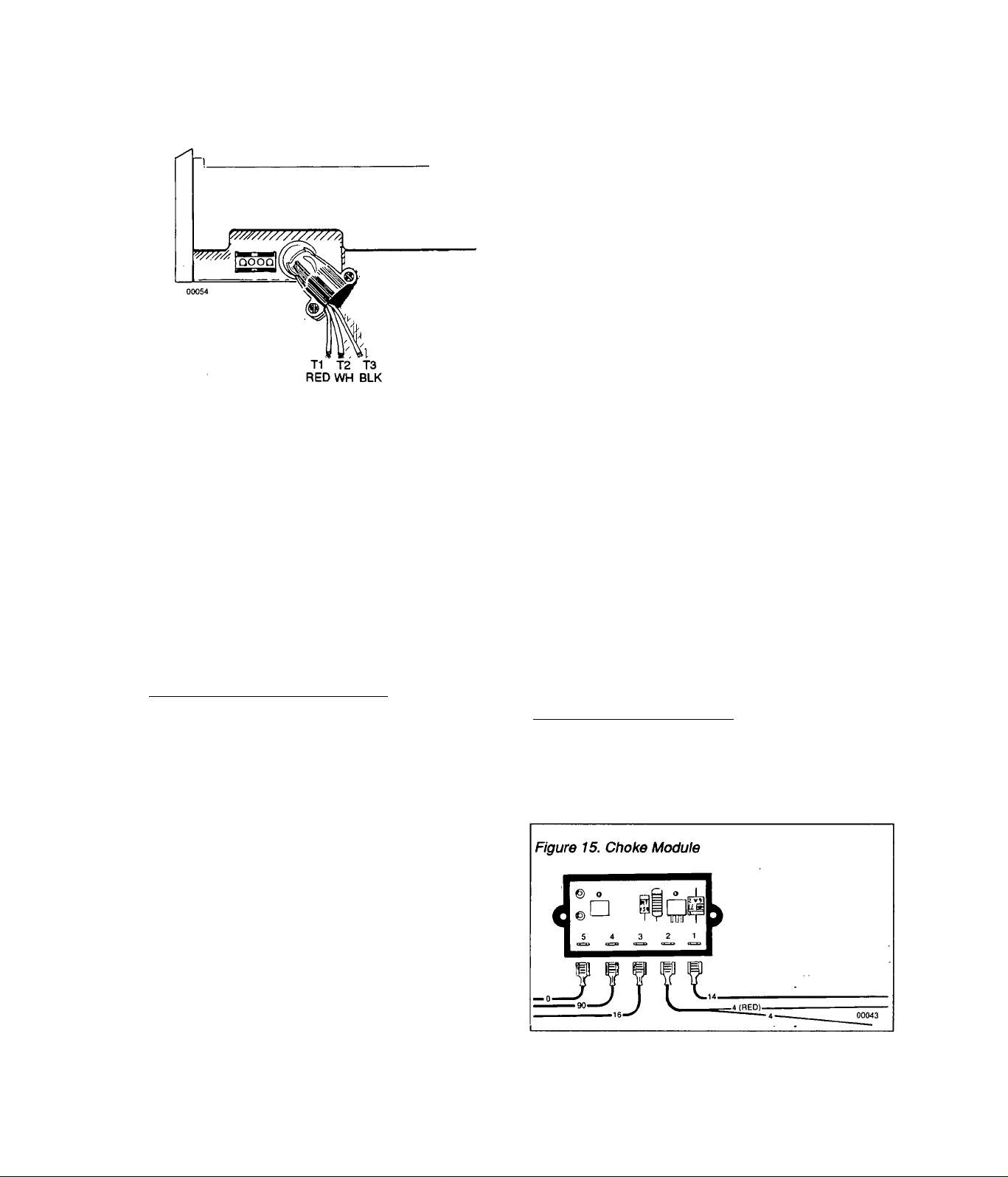
Test Procedure: Test the Field Boost circuit as follows
(Figure 15):
1. Disconnect Wires 4 from Pin 2 of the Choke Module
CM.
___________________
A. Generator may be overloaded. Add up the wattage or
amperage of all electrical loads being operated at one
20
Page 23
2. Connect the positive (+) test iead of the a d-c voitnieter
to Pin 2 of Choke Moduie CM. Connect negative (-) test
iead to a ciean frame ground.
3. Crank the engine. The voitmeter should indicate about
7-10 volts d-c with engine cranking.
Test Results:
A. Engine won’t crank: Go to Problem No. 1.
B. Engine cranks but no d-c voltage is indicated: Replace
Choke Module CM and recheck for proper voltage. If
voltage is good, STOP test.
C. Engine cranks and normal voltage is indicated: Con
tinue test.
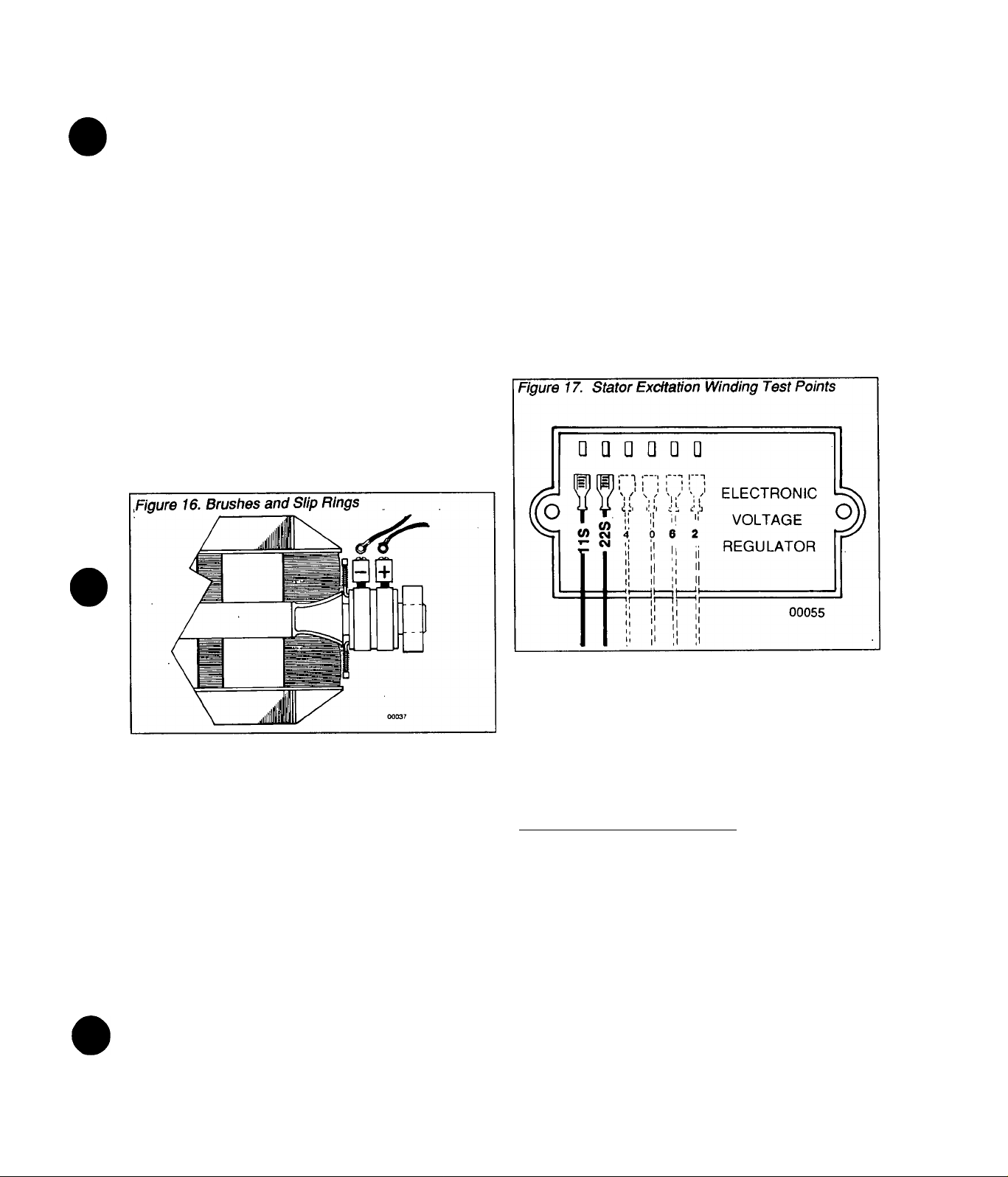
4. Gain access to Brushes and Slip Rings (Fig. 16).
5. Connect the positive lead of a d-c voltmeter to the
terminal of the positive (+) brush (RED lead connection).
Connect voltmeter test lead to a clean frame ground.
6. Crank engine. The voltmeter should indicate about
7-10 volts d-c with engine cranking.
Step 7 - Check Stator Excitation Windings
Test Procedure: Disconnect Stator Excitation Winding
output leads 2 and 6 (Fig. 17) from the Electronic Voltage
Regulator. Set a VOM to its "Rxl" scale and zero the
meter. Connect VOM test leads across terminal ends of
Wires 2 and 6. The VOM needle should swing upscale
and Indicate the following resistance:
NP45G Units = 2.2 Ohms
NP55G Units = 1.8 ohms
NP65G Units = 1.6 ohms
*AII resistance values are plus or minus 10%.
Now, set the VOM to its "Rxl 0,000" scale and again zero
the meter. Connect one VOM test lead to Wire 2, and the
remaining test lead to a dean frame ground. You should
not detect any upscale movement (infinity) of the VOM
needle.
Test Results:
A. Engine won’t crank: Go to Problem No. 1
B. Engine cranks and no d-c voltage indicated, but volt
age was indicated in Item 3 of test: Repair or replace
Wire 4 between Choke Module CM and the positive (+)
brush.
C. Engine cranks and normal voltage indicated: Go to
Step 7.
Test Results:
A. Excitation windings check GOOD: Go to Step 8. .
B. Excitation windings check BAD: Replace Stator As
sembly.
NOTE: Also see INSULATION RESISTANCE TESTS
on Page 9. Typically, In the above test, a low resis
tance indicates a shorted condition; a high reslstance Indicates an open condition.
Test 8 ■ Check Stator a-c Power Warnings
Test Procedure:, Test the Stator (Fig. 18) a-c power
windings as follows:
1. Disconnect a-c power winding output leads 11 and 22
from the Electronic Voltage Regulator.
2. Disconnect a-c power winding output lead 33 from
Circuit Breaker CB1.
3. At the wire nut junction of a-c output leads 22 and 44,
separate the two wires.
_________________
21
Page 24
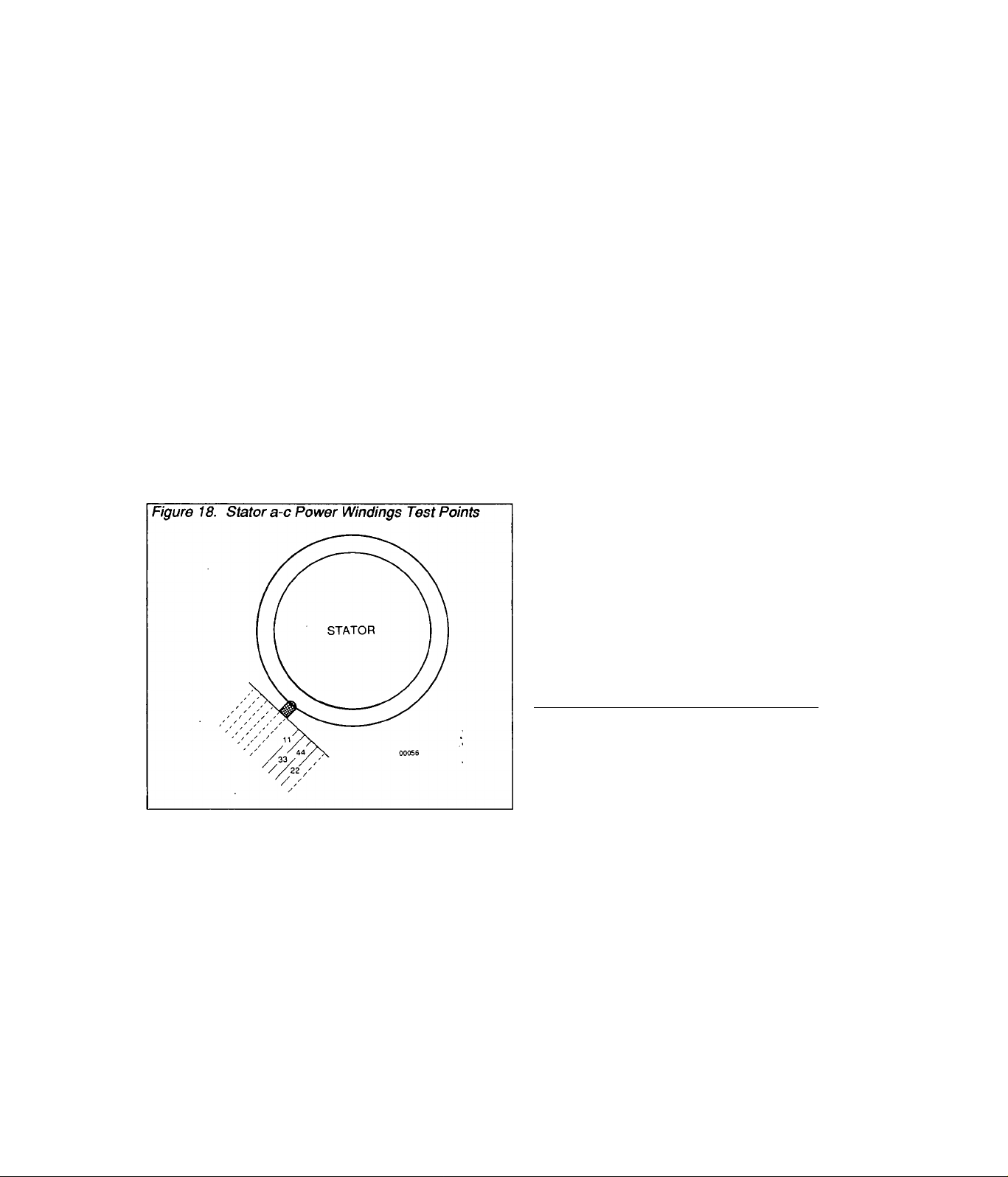
4. Set a VOM to its "Rx1" scale and zero the meter.
Connect VOM test leads across wire ends of Wires 11
and 22 and note the resistance reading, in ohms. Resis
tance should be as follows (plus or minus 10%);
NP45G Units = 0.4 ohms
NP55G Units = 0.3 ohms
NP65G Units = 0.2 ohms
5. Connect VOM test leads across wire ends of Wires 33
and 44. Again, note the resistance. Resistance should
be the same as in Item 4 above.
6. Set VOM to its "Rxl 0,000” scale and zero the meter.
Connect one VOM test lead to Wire 11 and the second
test lead to frame ground. The VOM needle should not
move upscale (infinity). Now, connect one test lead to
Wire 33 and the second lead to frame ground. Meter
should indicate infinity.
Test Results:
A. Power Windings check GOOD: Go to Step 9.
B. Power Windings check BAD: Replace Stator Assemb
ly-
2. Set a VOM to its "Rxl: scale and zero the meter.
Connect VOM positive (+) test lead to the positive (■<-) Slip
Ring (nearest the Rotor bearing). Connect negative (-)
VOM test lead to the negative (-) Slip Ring. Meter should
indicate the following resistance (plus or minus 10%) at
20°C (68®F).
NP45G Units =13.9 ohms
NP55G Units = 15.5 ohms
NP65G Units = 11.1 ohms
3. Reassemble Brushes and Brush Holder, retain Brush
Holder and Wires. Make sure Brushes are properly
seated in Brush Holder and are contacting the Slip Rings
properly. Rotate Rotor several times to seat Brushes
against Slip Rings.
Test Results:
A. Rotor circuit checks GOOD: Go to Step 10.
B. Rotor circuit tests BAD: Repair or replace defective
wire(s) or brushes. Replace defective Rotor Assembly.
Step 10 - Check Voltage Regulator Sensing
NOTE: Sensing signals to the Electronic Voltage
Regulator are delivered via Wires 11 and 22. Loss of
these sensing signals to the Regulator due to an
open or shorted condition (in a non-compensated
Regulator) normally means a "Full Field" condition
and resultant high a-c voltage output. However, the
NP series generators are equipped with a VoHage
Regulator that provides automatic protection
against an open sensing circuit and the resultant
high voltage condition. Should sensing wires 11 or
22 open, Voltage Regulator action will automatically
open the Excitation circuit to the Rotor and a-c
output voltage will drop dramatically. Total a-c volt
age output from the Stator a-c power windings will
be a result of residual Rotor magnetism only.
Step 9 - Check Rotor (Field) Circuit
Test Procedure: Use a VOM to test Wire 4, between
Electronic Voltage Regulator and Choke Module for open
or shorted condition. Wire 4 between Choke Module and
Brushes was previously tested in Step 6. Then, inspect
brushes and slip rings and test Rotor as follows:
1. Remove Wires 4 and 0 from Brushes, then remove
Brush Holder. Inspect Brushes and Brush Holder.
Replace if cracked, damaged, worn excessively, etc.
Inspect Slip Rings. If they are dull or tarnished, polish
with fine sandpaper. DO NOT USE ANY METALLIC
GRIT TO CLEAN SLIP RINGS. Use low pressure air (25
psi or less) to blow away cleaning residue.
Test Procedure: Recheck Wires 11 and 22, between the
Electronic Voitage Regulator and the Stator, as outlined
in Step 8.
Test Results:
A. Wires 11 and/or 22 indicate open or shorted condition:
Repair or replace wires as necessary.
B. Wires 11 and 22 check GOOD: Go to Step 11.
Step 11- Check/Adjust Voltage Regulator
Test Procedure: Refer to ADJUSTMENTS section.
With correct a-c frequency indicated, try adjusting the
Voltage Regulator. Frequency and voltage must both be
within the specified limits.
Test Results:
A. Frequency GOOD, cannot adjust in the correct volt
age: Replace the Voltage Regulator, adjust and test unit.
B. Frequency and Voltage both GOOD: STOP tests.
22
Page 25

ENGINE TROUBLESHOOTING
General
Most problems pertinent to engine operation may be clas
sified as one (or a combination) of №e following:
1. Will not start
2. Hard Starting
3. Lack of power
4. Vibration
5. Overheating
6. High oil consumption
When the cause of a problem is not readily apparent, per
form a check of the engine’s Compression, Ignition and
Carburation systems. Checkout of these systems, if per
formed in a systematic manner, can usually be done in a
few minutes. It is the fastest and surest method of finding
the cause of a problem.
What appears to be an engine problem may sometimes
be caused by the system that the engine is driving. For
example, overloading the generator (exceeding its wat
tage capacity) can cause the same indications as an un
derpowered engine. A shorted condition in the generator
or in electrical loads connected to the generator can also
appear to be an underpowered engine.
Checking Engine Compression
For instructions and information on checking engine com
pression, refer to the ENGINE SERVICE MANUAL. If
compression is poor, look for:
1. Loose spark plug(s)
2. Loose cylinder head bolts
3. Blown head gasket(s)
4. Burned valves or valve seats
5. Insufficient valve tappet clearance
6. Warped cylinder head(s)
7. Warped valve stems
8. Worn cylinder bore and/or rings
9. Broke connecting rod(s)
Check Engine ignition
Checkout and servicing of the engine ignition system is
discussed in detail, in the ENGINE SERVICE MANUAL.
To check ignition system operation, connect a SPARK
TESTER to the end of a the Spark Plug wires. Then, crank
the engine with both spark plugs removed. If a hot blue
spark jumps the Spark Tester gap, you may assume the
Ignition System is working properly. If spark jumps the
Tester gap, you may wish to try new spark plugs. If spark
does NOT jump the Tester gap, look for:
1. Defective gnition Module(s) IM1 and IM2
2. Defective Ignition Shutdown Module ISD
3. Defective Control Relay CR2
NOTE: If engine runs but misses during operation,
check to see If Ignition System Is at fault by connect
Ing the Spark Tester between the high tension Spark
Plug wire and the Spark Plugs. A spark miss will be
readily apparent
Check Carburetion
See TROUBLESHOOTING GUIDELINES. Before
making a carburetion check, make sure (a) an adequate
supply of fuel is available, (b) all fuel shutoff valve(s) are
open, and (c) fuel flow is adequate. Try adjusting the en
gine carburetor. Check automatic choke operation and
make sure the choke is adjusted property. If engine will
not start, remove and Inspect the Spark Plug.
If Spark Plug is WET, look for:
1. Overchoking
2. Excessively rich fuel mixture
3. Water in fuel
4. Intake valve stuck open
If Spark Plug is DRY, look for:
1. Leaking carburetor gasket(s)
2. Dirty or gummy carburetor
3. Intake valve stuck closed
4. Inoperative fuel pump
A simple check to determine if fuel is reaching the com
bustion chamber is to remove the spark plugs and pour
a small amount of gasoline through the Spark Plug hole.
Install and tighten Spark Plugs. Crank engine. If engine
fires a few times and then stops, look for the same con
ditions as a dry plug.
Other Problems that Might Affect Engine
Operation
1. Hard Starting or Will Not Start
a. Loose drive belts or pulleys- these can cause a
"backlash" effect that will counteract engine cranking
effort.
b. Starting under load- attempting to start with heavy
electrical loads applied can often cause problems.
c. Shorted condition in the generator or in connected
electrical loads can impose a heavy load on the en
gine, thus preventing start.
2. Vibration
a. Check for defective or damaged pulleys, drive
belts, or Rotor.
b. Check for loose mounting bolts and tighten.
3. Power Loss ■
a. Check for binding or drag in drive train (pulleys
and belts)
b. Check for defective Rotor bearing.
c. Check for Rotor contact with Stator windings.
d. Check for excessive drive belt tension.
4. Noise
a. Check for a damaged Rotor and/or Stator
b. Check for loose or damaged pulleys and drive
belts.
23
Page 26

ADJUSTMENTS
General
This section is inciuded with other a-c generator informa
tion, because the covered information is so important to
proper generator operation and correct a-c output. The
engine governor adjustment may belong in the ENGINE
SERVICE MANUAL. However, that adjustment is so
important to correct a-c output frequency and voltage that
it is included here.
Adjustments included in this section include thefollowing:
1. Engine governor adjustment.
2. Voltage Regulator adjustment
3. Automatic Choke adjustment.
NOTE: An optional LP gas (propane) fuel system Is
available for use with the NP series generators.
Instructions for the installation and adjustment of
the LP gas conversion kit are Included with the kit.
Engine Governor Adjustment
A Also see ROTOR ROTATIONAL SPEED on Page 4
of this Manual. The engine governor is generally ad
justed to deliver a generator a-c output frequency of
61-62 Hz, with no electricai loads connected to the gen
erator. Following the no-load adjustment of engine
speed, unit operation shouid be checked with a ioad
applied. Adjust the engine governor as foiiows:
6. Check a-c frequency; it should be 61 -63 Hz. If not, turn
ADJUSTER NUT until frequency is correct.
7. With governed speed at 61-63 Hz (no-load), check
voltage reading. Voltage should be 122-126 volts. If not,
adjustment of the Voltage Regulator is required.
1. Visually inspect ANTI-LASH SPRING, make sure it is
not broken or disengaged. Spring ends must be hooked
into GOVERNOR LEVER at bottom end and into car
buretor THROTTLE LEVER at top.
2. Loosen GOVERNOR CLAMP NUT.
3. Push spring end of GOVERNOR LEVER ail the way
up, to wide open throttle position. While holding the
LEVER down, insert a screwdriver into siotted end of
GOVERNOR SHAFT and rotate SHAFT fuliy
counterclockwise. Then, tighten the GOVERNOR
CLAMP NUT to 100 inch-pounds of torque.
CAUTION!: Governor shaft MUST be rotated fully
counterclockwise with throttle wide open or full
governor travel will not be reached. Governor clamp
nut must be tight Or full governor travel may be lost
due to vibration.
4. Connect an accurate a-c frequency meter and
voltmeter across generator a-c output leads T2 (white)
and T3 (black) for Series NP45G/NP55G; or across ieads
T1 (red) and T2 (white) for Series NP65G. See Step 3
under Probiem No. 6 on Page 19. (Check A-C VOLTAGE
AND FREQUENCY).
5. Start the engine. Let it stabilize and warm up for a few
minutes with NO ELECTRiCAL LOADS APPLiED TO
GENERATOR.
__________________________________
Voltage Regulator Adjustment
CAUTION: DO NOT adjust the Voltage Regulator
until a-c output frequency Is correct. See ENGINE
GOVERNOR ADJUSTMENT.
B Check that a-c frequency is correct, as outiined in
ENGiNE GOVERNOR ADJUSTMENT. If frequency Is
within stated limit (61-63 Hz), a-c voltage output should
be 122-126 volts. If voltage is not correct, adjust the
Voitage Regulator by turning the VOLTAGE ADJUST
potentiometer slowly until a-c voltage Is within the stated
limits. Voltage regulator is mounted in the generator
24
Page 27

Automatic Choke Adjustment
C Check automatic choke operation and (if necessary)
adjust the choke as foiiows:a. Check Choke Operation:- Crank the engine whiie ob
serving automatic choke operation, initiaily, the Choke
Soienoid shouid energize to dose choke for about 0.2 to
0.4 seconds and then de-energize for about 2 seconds to
open the choke. This open/ciose cycie shouid repeat itseif untii the engine starts and cranking is terminated.
b. Pre-Choke Adjustment:- With engine cold and Choke
Solenoid NOT actuated, check that carburetor choke
plate is about 1/8 Inch away from its full open position. If
necessary to obtain the desired setting, use needle nose
pliers to bend tip of BI-METAL.
c. Choke Solenoid Adjustment:- Loosen screws that
retain the CHOKE SOLENOID to its retaining bracket.
Slide the CHOKE SOLENOID in the slotted holes to ad
just axial movement of the SOLENOID plunger. Adjust
the axial movement so that, with the carburetor choke
plate closed, the CHOKE SOLENOID plunger Is just bot
tomed in the solenoid coil (plunger at full actuated posi
tion). With choke plate closed and plunger bottomed in
the coil, tighten the two screws. Then, crank engine and
check choke operation.
25
Page 28

Drawing No. 75464
Page 29

Exploded View of Sheet Metal
Drawing No. 75464
'EM
1
2
3 67198-N
4
5
6
7 74904
8 56892
9
10
11
12
13
14
15
16
17
18
19 73191
20
21
22
23 11-74260
24
25
26
27 22717-B 1 GROMMET. Rubber
28
29 67866
30 74955
31 74965
32
33
34 48031-E
35
36 74956
37 42907
38
39
40
41
42 29289
43
PART NO.
67877 1
67890
74915 1 SCREEN, Air Inlet
63036 6
70520
74903
74916
74908 8
73190
73189
73188
74902
43146 4
22097 4 LOCKWASHER- M6
48571
22129 2
75246
74900
73186
23484-D 1
22717-A 2 GROMMET, Rubber
22447 1
40936
47662-BB
46509
08-74260
09-74260
48031-D
73132
REQ’D DESCRIPTION
1 ENGINE ASSY (See EXPLODED VIEW OF V-TWIN
ENGINE)
KEY. Woodruff- 6 X 25
1 WASHER, Belleville
1
1
22
1 MODULE, Shorting
1
1
1 WRAPPER- No. 2 Cylinder
1
1
2 WRAPPER, Barrel
1
2
4
1 WIRE ASSY- No. 16
1 COVER, Starter
1
1
1
1
1
1 CLAMP, Hose
1
1 BRACKET, Oil Makeup Pump
1
1
1
1 WIRE ASSY (Ground)-15" long
2 CLAMP, Hose
2 TAPE, Foam
2 BOOT, Spark Plug
NUT, Hex-M20-1.50
SCREW (Crlmptite)- No. 8-32 x 1/4"
HOUSING, Engine Top
SCREW (Crlmptite)- No. 10-32 x 3/8"
SCROLL, Flywheel
COVER, Base #2
SCREW (Taptite)- M5 x 10mm
COVER. Valley
WRAPPER- No. 1 Cylindert
CAPSCREW, Hex Head- M6-1.00 x 10mm
COVER, Base- No. 1 Cylinder
CAPSCREW, Hex Head- M8-1.25 x 10mm
LOCKWASHER- M8
SCREW (Taptite)- 3/8"-16 x 1/4"
WRAPPER, Crankcase
BUSHING, Snap
O-RING
PROBE, Oil Makeup
RETAINER, Oil Makeup Probe
WASHER (Shakeproof)- M6
SCREW, Socket Head- M6-1.00 x 8mm
HOSE- 5/16" ID
CAPSCREW, Hex Head- M8-1.25 x 16mm
PUMP, Oil Makeup
WIRE ASSY (Ground)- 5.5" long
27
Page 30

Drawing No. 75218
28
Page 31

Exploded View of Base & Pulleys
Drawing No. 75218
ART NO.
1 72372 1
2
72382
3 38353
25017 4
4
22237 12
5
22241
6
7
72391
73147 2
8
45771
9
10 52858
11 51730
12 29459
75215
13
14
73146
15 75209
73174
16
67897 1
17
55173
18
19 72383
56892
20
75224-A
21
A
V
75224-B
75224-C
73106-A 1
ZZ
73106-B
73106-C
75216
23
24 49451
25 42633
26 72381
27 73118
28 74906
74908 9
29
72375
30
31 73185
32 22097
74909
33
75242
34
74910
35
36 73156
37 49099
48031-E
38
47662-U
39
47662-BQ 1
40
50190
74913
REQ’D
•
43 73181
1
4
4
2
2
8
2
2
2
4 SLiDE (Nylon)
2
1
4
2
32
1
1
1
1
1
1
5
1
1
1
12
1
1
1
1
4
4 CLAMP, Hose- 3/8"
5
DESCRIPTION
BASE, Mounting
PAN, Collector
MOUNT (Rubber)
CAPSCREW, Hex Head
3/8"-16 X 1/2"
LOCKWASHER- MIO
NUT, Hex - 3/8"-16
SKID, Rubber Mount
BOLT, Safety
NUT, Hex-M8-1.25
NUT, Flanged Lock- M8-1.25
CAPSCREW, Hex Head
M8-1.25 X 60mm
SPRING, Belt Tensioner
WASHER, Spring Center
SUPPORT, Nylon Slide
manìpolo. Exhaust
GASKET, Exhaust Manifold
CAPSCREW, Hex Head
M8-1.25 X 20mm (Grade 10.9)
GASKET, Collector Pan
SCREW (CrimptHe)- No. 10-24
PULLEY, Engine Fan (NP45G)
PULLEY, Engine Fan (NP55G)
PULLEY, Engine Fan (NP65G)
PULLEY, Generator Fan (NP45G)
PULLEY, Fan (NP55G Only)
PULLEY, Fan (NP65G Only)
BELT (Poly V 4L)- 40"
WASHER, Pulley Retainer
CAPSCREW, Socket Head
3/8"-24x1" (Grade 5)
GUIDE, Blower Housing
CAPSCREW, Hex Head
3/8"-24 X 2-1/2"
SCREW (TapWe)- M6-1.00 x 20
SCREW (Taptite)- M5-0.80 x 10
HOUSING, Blower
SPACER, Blower Housing
LOCKWASHER- M6
CAPSCREW, Hex Head
M5-0.80 X 70mm
SPRING, Generator Set Mount
1
1
1
1
1
1
TANK, Oil Makeup
CAP, Oil Makeup Tank
ELBOW- 90' Barbed
HOSE- 3/8" X 6" long
HOSE- 3/8" ID X 25" long
WASHER, Tank Retainer
CAPSCREW, Hex Head
M6-1.00 X 110mm
TUBE, Oil Fill and Drain
EM PART NO.
44 74958
67871
45
67866
46
47 73135
73138
48
74936
49
43790
50
47662-BC
51
52 35461
69811
53
65852
54
52857
55
73179
56
57 70185
60108
58
59 74948
74950
60
74951
61
73134
62
38750
63
64 74949
69547
65
46453
66
67
29289
35472
68
75281
69
43181
70
43182
71
72 22473
75237
73
61274
74
75474
75
73176
76
77 74907
75226
78
56892
79
75229
80
75227
81
82 43116
22473
83
22097
84
72384-B
85
74908
86
87 74906
76267
88
REQ’D
1
1 0-RING, Cap
1
1
1
1
1
1
1
1
1
1
1
1
1
3
1
1
1
3
1
1
1
-
1
1
2
2
1
4
1
1
1
1
1
4
1
1
4
4
4
1
3
1
DESCRIPTION
CAP & DIPSTICK ASSY
O-RING, Drain
PIPE, OH Drain Adapter
ELBOW, 90’ - 3/8" NPT
NIPPLE- 3/8" NPT X 2-1/4"
ELBOW- 3/8’ NPT X 3/8’
HOSE- 3/8’ X 10-1/2"
FITTING, Barbed-1/4’ NPT x 3/8
CAP, Hex - 1/4’ NPT
CLIP, Hose Retainer
NUT, Flanged Lock- M6-1.00
SUPPORT, Oil Filter
FILTER, Oil (FRAM #PH3614)
SWITCH, OH Pressure
FITTING- 5/16’
TUBE, Outer Oil
TUBE, Inner OH
ADAPTER, OH Pad
CAPSCREW, Hex Head
M6-1.00 X 30mm
FITTING, Barbed 90’ - 5/16’
GASKET, oil Pad
LUG, Grounding
TAPE, Foanv 1/16" thick x 8 ft.
CLAMP
SWITCH, High Temperature
SCREW, Pan Head- M3-0.50
LOCKWASHER- M3
FLATWASHER- M6
WASHER, Spring Retainer
SWITCH, High Water Temp.
CAP, Vynyl-17D X 42L x 2H
ELBOW, Exhaust
CLAMP, Exhaust- 1-1/8"
COVER, Air
SCREW (Crimptite)- No. 10-32
GASKET, Slide Pan
SLIDE PAN
CAPSCREW, Hex Head
M6-1.00 X 12mm
FLATWASHER- M6
LOCKWASHER- M6
COVER, Exhaust Outlet
SCREW (TapWe)- M5 x 10mm
SCREW (TapWe)- M6-1.00 x 20
2
SPACER (Plastic)
29
Page 32

Drawing No. 75231
30
Page 33

Exploded View of Alternator and Panel
Drawing No. 75231
ITEM PARTNO. REQ’D DESCRIPTION
72376 1 CARRIER, Lower Bearing
73160 1 ROTOR ASSY- NP45Q
73161
73162
3
31971
4
73159 1 BEARING, Ball
73164
5
73165 1
73166 1
6 72379
7
73145 4 STUD, Stator
8 45771
9
66386
10 66849 2 SCREW- M5-0.80 x 15mm
11
75203 1
12
74908 1 SCREW- M5-0.80 x 10mm
75214 4
13
14
27756
15 74905 1
16 52858
17
29451
18
75201
19 74906
20 74939 1
22097
21
22 43116 4 CAPSCREW, Hex Head
56739
•
74260-10 1 CABLE, Starter
53407
25
26
74911
27 48031-D 4
28 75213 1 FILTER, Fuel
29 71908 4 MOUNT, Rubber
30 22473
31 49813 7 NUT, Hex - M6
32 75202 1
1
1 ROTOR ASSY- NP65Q
1 BEARING, Ball
1
1 CARRIER, Upper Bearing
4
1 HOLDER, Brush
4
4
-
1 BRACKET, Panel
4
11
1
2
1
4 FLATWASHER- M6
ROTOR ASSY- NP55Q
STATOR ASSY- NP45G
STATOR ASSY- NP55G
STATOR ASSY- NP65G
NUT, Hex-M8-1.25
CLAMP, Stator Wire
SPACER, Cover
WASHER- Nylon
HOUSING, Top
NUT, Flanged Lock- M8-1.25
TAPE, Foam Rubber- 3 feet long
SCREW- M6-1.00 X 20mm
PUMP, Fuel
LOCKWASHER- M6
M6-1.00 X 12mm
CONTACTOR, Starter
CABLE, Panel Ground
ELBOW, Pump Inlet
CLAMP, Hose-5/16"
HOUSING, Panel
EM PART NO. REQ’D DESCRIPTION
34616
33
39271 1
34
73601
35
74074
36
37 22264 5
51787
38
75235 2 SCREW- M5-0.80 x 30mm
39
75234
40
41 74095
75210-A 1 BLOCK, Tenninal
42
49226
43
44 65795
75205
45
75204
46
47 75200
75208
48
32300
49
22676
50
53650
51
75244 1 CABLE ASSY- Remote
52
75471 1 BREAKER, Circuit- 30 amp
53*
54** 75470 1 BREAKER, Circuit- 20 amp
47662-AW 1
55
56 73513
57 57345
63036 2 SCREW-No. 8-18 X 1/4"
58
59 33136
22155
60
22985
61
62 22188
51715 5
63
64 25433
65 56893
66 36900
67
73129
1
1
1
5 SCREW, Hex Head- M4-0.70
1
1 CAPSCREW, Hex Head
2 LOCKWASHER- M5
1 RECTIFIER, Battery Charge
1
1 RELAY-12 volts d-c
1
1
1 HOLDER, Fuse
1
1 CONNECTOR
4 SCREW- No. 10-32 x 1/2"
2
4 SCREW, Hex Head Machine
4 LOCKWASHER- No. 6
4 FLATWASHER- No. 6
4 NUT, Hex - No. 6-32
1
1 SCREW (Crimptite)- No. 10-24
4 SCREW, Pan Head Machine
1
CONNECTOR- 3/4"
CONNECTOR, 90’ - 3/4"
MODULE ASSY- Choke
REGULATOR, Voltage
LOCKWASHER- M4
RESISTOR
M6-1.00 x 60mm
RELAY-12 volts a-c
PANEL, Control
SWITCH, Start/Stop
FUSE-15 amp
HOSE- 5/16" ID X 4-1/2"
LUG
No. 6-32 X 5/8"
NUT, Hex- M4-0.70
LUG, Ground
No. 6-32x1/4"
DECAL- Control Panel
31
* Used on NP65G Series
** Used on NP45G & NP55G Series
Page 34

ELECTRICAL FORMULAS
DESIRED DATA
Kilowatts*
KVA*
Horsepower*****
Amperes**
Amperes***
Amperes****
Alternating Cun
1-PHASE
Volts X Amps X Power Factor
1000
Volts xAmps
1000
Volts X Amps X lOOxP.F.
746 X Efficiency
H.P, X 746 X Efficiency
Volts X 100 xP.F.
Kilowatts X 1000
Volts X P.F.
kVAxIOOO
Volts
rent
3-PHASE
1.73 X Volts X Amps x Power Factor
1.73 x Volts x Amps
1.73 X Volts X Amps X 100 x P.F.
746 X Efficiency
H.P. X 746 X Efficiency
1.73 X Volts X 100 X P.F.
Kilowatts X 1000
1.73X Volts X P.F.
kVAxIOOO
1.73 X Volts
1000
____
1000
Frequency RPM x Rotor Poles
2x60
No. of Rotor Poles
RPM
* Generator output or loa
** When Horsepower is kr
*** When Kilowatts is knov
**** When kVA is known
***** Engine output
d input
lown
vn
2 X 60 X Frequency
RPM
2 X 60 X Frequency
No. of Rotor Poles
RPM X Rotor Poles
2x60
2 X 60 X Frequency
RPM
2 X 60 X Frequency
No. of Rotor Poles
32
Page 35

SPECIFICATIONS
Series NP45G
Model Number...................................................9009-0
Rated Maximum Power
Rated a-c Voltage
Rated Maximum Current
At 120 volts a-c............................................37.5 amps
At 240 volts a-c............................................18.75 amps
Rated Frequency
Phase.................................................................1-Phase
No. of Rotor Poles............................................2
Governed Rotor Speed at No-Load
Rotor & Stator Winding Nominal Resistance
Battery Charge Windings
Excitation Winding
Stator a-c Power Windings
Rotor Windings
....................................
.............................................
..............................................
................
...........................
.....................................
........................
...........................................
4500 watts
120 volts*
60 Hz
3720 rpm
0.12 ohm
2.21 ohms
0.42 ohm
13.9 ohms
Series NP55G
Model Number
Rated Maximum Power....................................5500 watts
Rated a-c Voitage.............................................120 volts*
Rated Maximum Current
At 120 voits a-c
At 240 volts a-c
Rated Frequency..............................................60 Hz
Phase
................................................................
No. of Rotor Poles............................................2
Governed Rotor Speed at No-Load
Rotor & Stator Winding Nominal Resistance
Battery Charge Windings
Excitation Winding
Stator a-c Power Windings
Rotor Windings...........................................15.5 ohms
..................................................
...........................................
...........................................
................
..........................
.....................................
........................
9010-0
45.8 amps
22.9 amps
1-Phase
3720 rpm
0.09 ohm
1.84 ohms
0.29 ohm
Series NP65G
Model Number...................................................9011-0
Rated Maximum Power
Rated a-c Voltage
Rated Maximum Current
At 120 volts a-c............................................54.2 amps
At 240 volts..................................................27.1 amps
Rated Frequency
Phase.................................................................1-Phase
No. of Rotor Poles............................................2
Governed Rotor Speed at No-Load
Rotor & Stator Winding Nominal Resistance
Battery Charge Windings
Excitation Winding
Stator a-c Power Windings
Rotor Windings...........................................11.1 ohms
* All units can be reconnected to 120/240 volts, 1 phase,
60 Hz, a-c output. See GENERATOR A-C CONNEC
TION SYSTEM on Page 5.
....................................
.............................................
..............................................
................
...........................
.....................................
........................
6500 watts
120 volts*
60 Hz
3720 rpm
0.07 ohm
1.67 ohms
0.23 ohm
33
Page 36

'NP" Serles generators are designed and manufactured by
GENERAC CORPORATION • P.O. BOX 8 • WAUKESHA, Wl 53187
(414) 544-4811 • FAX 414/544-4851
Revision 4 (08/31/S1)
 Loading...