

Page 1

POWER SYSTEMS, INC.
H-100 Control Panel
®
Technical Manual
This manual should remain with the unit.
Page 2

IMPORTANT SAFETY INSTRUCTIONS
H-100 Control Panel Technical Manual
SAVE THESE INSTRUCTIONS – The manufacturer suggests that these rules for safe operation
be copied and posted in potential hazard areas. Safety should be stressed to all operators
and potential operators of this equipment.
Study these SAFETY RULES carefully before installing, operating, or servicing this equipment. Become
familiar with this manual and all literature pertaining to the generator set and related equipment. This
equipment can operate safely, efficiently, and reliably
only if it is properly installed, operated, and maintained. Many accidents are caused by failing to follow
simple and fundamental rules or precautions.
Generac cannot anticipate every possible circumstance that might involve a hazard. The warnings in
this manual, and on tags and decals affixed to the
equipment, are, therefore, not all inclusive. If using
a procedure, work method, or operating technique
the manufacturer does not specifically recommend,
ensure that it is safe for others. Also make sure the
procedure, work method, or operating technique utilized does not render the equipment unsafe.
GENERAL HAZARDS
For safety reasons, the manufacturer recommends
•
that this equipment be installed and serviced by
an Authorized Service Dealer or other qualified
electrician or installation technician who is familiar with applicable codes, standards, and regulations. The operator also must comply with all such
codes, standards, and regulations.
When working on this equipment, remain alert
•
at all times. Never work on the equipment when
physically or mentally fatigued.
Inspect the equipment regularly, and promptly
•
repair or replace all worn, damaged or defective
parts, using only factory-approved parts.
Before performing any maintenance on the gen-
•
erator or any related equipment, disconnect the
generator’s battery cables and remove panel fuse
to prevent accidental startup. Disconnect the cable
from the battery post, indicated by a NEGATIVE,
NEG, or (–) first. Reconnect that cable last.
Do not handle any kind of electrical device while
•
standing in water, while barefoot, or while hands or
feet are wet. DANGEROUS ELECTRICAL SHOCK
MAY RESULT.
If people must stand on metal or concrete while
•
installing, operating, servicing, adjusting, or repairing this equipment, place insulative mats over a
dry wooden platform. Work on the equipment only
while standing on such insulative mats.
Wire gauge sizes of electrical wiring, cables, and
•
cord sets must be adequate to handle the maximum electrical current (amperage) to which they
will be subjected to.
Before installing or servicing this equipment, make
•
sure that all power voltage supplies are positively
turned off at their source. Failure to do so will result
in hazardous and possibly fatal electrical shock.
When installed with an automatic transfer switch,
•
the generator may crank and start anytime, without warning. To prevent injuries caused by sudden
start-up, disable the generator’s automatic start
circuit before working on, or around, the unit.
Then, place a “Do Not Operate” tag on the generator control panel and on the transfer switch.
In case of an accident caused by electric shock,
•
immediately shut down the source of electrical
power. If this is not possible, attempt to free the
victim from the live conductor. AVOID DIRECT
CONTACT WITH THE VICTIM. Use a nonconducting implement, such as, a rope or board, to free
the victim from the live conductor. If the victim
is unconscious, apply first aid and get immediate
medical help.
Never wear jewelry when working on this uipment.
•
Jewelry can conduct electricity, resulting in electric
shock, or may get caught in moving components,
causing injury.
FIRE HAZARDS
ELECTRICAL HAZARDS
Generators produce dangerous electrical voltages
•
and can cause fatal electrical shock. Avoid contact
with bare wires, terminals, connections, etc., while
the generator and related equipment are running.
Ensure all appropriate covers, guards, and barriers are in place before operating the equipment.
If working around an operating unit, stand on an
insulated, dry surface to reduce potential shock
hazards.
• For fire safety, the generator and related equipment must be installed and maintained properly.
Installation always must comply with applicable
codes, standards, laws, and regulations. Adhere
strictly to local, state, and national electrical
and building codes. Comply with regulations the
Occupational Safety and Health Administration
(OSHA) has established. Also, ensure that the
equipment is installed in accordance with the
manufacturer’s instructions and recommendations. Following proper installation, do nothing
that might alter a safe installation and render the
unit in noncompliance with the aforementioned
codes, standards, laws, and regulations.
Page 3

Table of Contents
H-100 Control Panel Technical Manual
Table of Contents
Safety Rules ........................................ Inside Front Cover
General Information ......................................................... 2
Introduction .................................................................... 2
Features .......................................................................... 2
Panel Setup ..................................................................... 2
Changing the Controller Configuration ........................2
Customization .............................................................. 2
The Measurement “Engine” ............................................. 3
Analog Channels .......................................................... 3
Analog Maths ............................................................... 3
Analog Alarms .............................................................4
Other Analog Options ..................................................5
Analog Sensor Ratings ................................................. 5
Output Functions ............................................................5
Spare Analog Channels ................................................ 5
Engine Management ........................................................ 6
Generator Parameters ..................................................6
Engine Settings ............................................................6
Starting and Stopping - Sequence Diagrams ................... 7
Voltage Regulator (Option) .............................................. 8
Governor (Speed Regulator) Option ................................ 8
Trending .........................................................................9
Remote Trending ......................................................... 9
Local Trending ...........................................................10
GenLink Local Trending Setup .................................. 10
Trigger/Collection Type ..............................................13
The ILC ......................................................................... 10
The Front Panel Display ................................................ 11
Left Display ................................................................ 11
Right Display ............................................................. 11
Left Display Pages ...................................................... 11
Right Display Pages .................................................... 13
Alarms .......................................................................13
Engine ........................................................................... 14
Status ............................................................................16
Service .......................................................................... 17
Generator ...................................................................... 18
Diagnostics ....................................................................19
Exercise/HTS ................................................................ 21
The Control Panel ......................................................... 23
The Alarm Log .............................................................. 23
The Event Log ............................................................... 23
Maintenance Settings .................................................... 24
Air/Fuel Ratio Control (Option) .....................................24
2
I
T Current Monitoring (Option) ................................... 24
Internal Exercise Function ............................................25
QuietTest® Setup Using GenLink ..................................25
Normal Exercise Setup Using GenLink ......................... 26
QuietTest® Setup Using Front Panel .............................. 27
Set Date and Time ........................................................ 33
Date and Time Setup Using GenLink ......................... 33
Date and Time Setup Using Front Panel .................... 33
Adjust Display Contrast ................................................ 34
Enable Generac Commercial Transfer Switch (HTS) .... 35
HTS Setup Using GenLink .........................................35
HTS Setup Using Front Panel ....................................35
Communications ........................................................... 37
Remote Annunciator Connection (Option) .....................37
New Generation GenLink (NGG) ................................... 37
GenLink Relay Control .............................................. 37
Set Engine Hours .......................................................37
Absolute Maximum Ratings ....................................... 37
Environmental Ratings ..............................................37
Appendix ............................................................................ 38
Appendix A — Analog Functions ...................................38
Appendix B — H-100 General I/O and Connector
Information ........................................... 40
H-100 Analog Inputs .................................................. 40
H-100 Digital Outputs ................................................41
H-100 Digital Inputs .................................................. 41
H-100 Digital Output Functions ................................. 42
H-100 Connector Pin Descriptions ............................46
Appendix C — Miscellaneous H-100
Internal Alsrms/Warnings ......................47
Notes ...................................................................................48
AUTHORIZED SERVICE
DEALER LOCATION
To locate the nearest AUTHORIZED SERVICE
DEALER, please call this number:
1-800-333-1322
DEALER LOCATION INFORMATION
CAN BE OBTAINED AT THIS NUMBER,
or visit the website at www.generac.com.
1
Page 4

General Information
H-100 Control Panel Technical Manual
INTRODUCTION
The H-100 Control Panel is an electronic control box
that functions as an advanced standby generator
controller. Its technology is based on the flagship PMDCP system with all its flexibility included. A familiar
user interface in the form of GenLink®-DCP is used
to program, monitor and change the parameters in
the unit. The interface appears the same as it does
for the PM-DCP.
Specialized programs are built into the H-100 Control
Panel to allow customers to configure spare I/O to
their own needs. For example, built in Integrated
Logic Controller (ILC) logic can eliminate the need
for ancillary external controllers. Everything can be
user customized from measurements to alarms to
the screen displays.
Why do we do this? Having one set of control firmware buys us the economy of scale which can be
passed on to the customer. It also has great technical
advantages. The H-100 Control Panel and all PM-DCP
products are built around a common “core” of firmware. This provides EVERY product with the same
technical tools. For example, both the H-100 Control
Panel and PM-DCP products can call out for assistance via a modem, every product can provide trending data for its measured parameters, any measured
value can be setup to create alarms or warnings, each
product has a built in ILC, etc. H-100 Control Panel
is very flexible.
FEATURES
Local/remote connection to a PC for GenLink®-
•
DCP communication.
Interface with up to four Generac Commercial
•
Transfer Switches (HTS).
Interface with up to two Remote Annunciator
•
Panels.
Customizable display.
•
New Generation GenLink.
•
Built-in Frequency and Voltage controller.
•
External modem option with dialout capability
•
upon alarm.
Communication via standard CAN bus and Modbus
•
protocols.
Programmable I/O channel properties.
•
Programmable alarm/warnings.
•
Alarm and event logging with time stamping.
•
Parameter logging and trending both to file and
•
graphical.
Built-in diagnostics.
•
Internal ILC for combinatorial logic functions
•
including analog inputs.
Spare customer programmable Analog input capac-
•
ity.
Spare customer programmable Digital I/O capac-
•
ity.
•
Firmware can be updated via Telephone line.
2
PANEL SETUP
CHANGING THE CONTROLLER
CONFIGURATION
The H-100 Control Panel controller is setup in the
factory to match the product it is shipped with and
generally no changes are required. For spares purposes the controller can be re-configured in the field
using the GenLink software tool and a PC.
If you need to change the function of the panel the
best way to get a basic setup for a product is to use
GenLink to download a “product file”. This will setup
all the basic parameters and just leave customization
and calibration to be done. Product files are available
on the web site for downloading cross referenced to
product serial numbers/generic product types. The
manufacturer does not recommend changing the
settings individually for a product as this is laborious and prone to human error. Some of the settings
require detailed knowledge of things like governor
settings which are not easily discernable.
Some configurations are changeable from the H-100
Control Panel touch pad and displays. These configurations will be described later and include:
Setting Display Contrast
•
Setting System Time and Date
•
Setting up/Enabling Internal Exercise
•
Enabling Interface with Generac Commercial
•
Transfer Switch (HTS)
CUSTOMIZATION
The controller is designed to be very flexible and
allow great levels of customization via the GenLink
tool. Once you have customized your controller, you
should save the settings away to floppy or hard disk
for backup. This can be done during the customization process, or at any time subsequent to customization by uploading the settings from the controller to
GenLink and then saving them to disk. The digital
outputs can be set to turn on from any one of a list
of functions, or they can be used as part of the builtin ILC. The digital inputs can be moved, inverted,
renamed, given delay times, made alarms, used
in the ILC, logged/not logged, etc. Refer to the section “MEASUREMENT ENGINE” for details. Analog
inputs are dealt with in the same section.
There are some parameters which are specific to the
product, such as an engine controller or transfer
switch. These are all customizable via GenLink. Refer
to the relevant section for details.
Page 5

THE MEASUREMENT "ENGINE"
The measurement “engine” is the key feature of the
system. All the inputs to the controller are processed
by this module. Each physical input is measured and
the result processed by an individual set of rules that
are set via a PC and GenLink. Normally, a product
is delivered with the inputs and outputs pre-configured and nothing needs to be done, however the
manufacturer has provided complete flexibility to
each measurement (except where product safety is
concerned). The inputs are divided into analog and
digital channels.
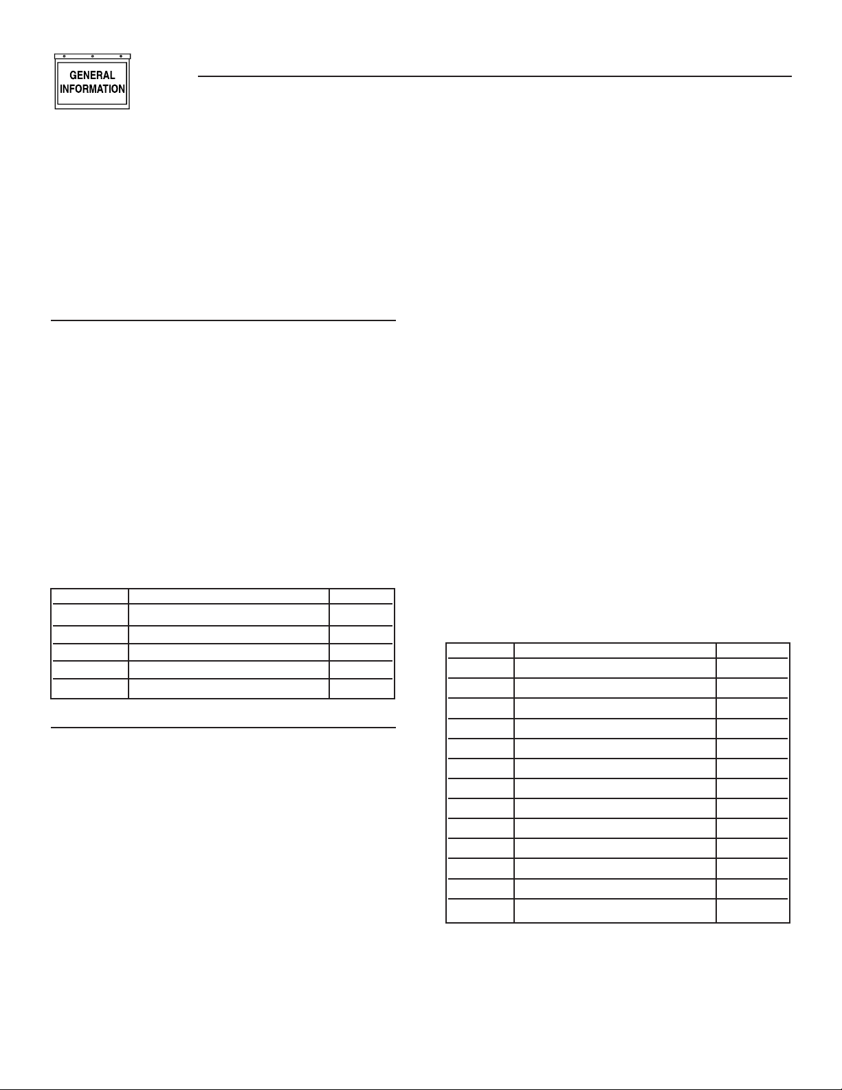
ANALOG CHANNELS
There are 23 analog channels of which 14 have fixed
functions. The remaining 9 channels are split between
product specific inputs (such as oil temperature),
and customer spares. The exact split depends on the
product. Table 1 shows the channel allocation.
Some of the 14 fixed channels are “DERIVED” readings in that they are calculated from the other readings. For example, power is calculated from both voltage and current. These are not real hardware channels, but they result in an analog reading that can be
treated as a “fixed channel” just like any other.
Table 1
General Information
H-100 Control Panel Technical Manual
ANALOG MATHS
Each of the 23 channels is processed by a set of measuring rules using constants that are set via GenLink.
Usually these constants can be changed by the customer. In the following illustration, the measurement
is represented by M and the GenLink constants are
in italics. The measurement is processed in the following order and the result is then stored for customer display or use.
M = M * Calibration Factor
This is used to calibrate out any reading inaccuracies where calibration factor is a number such that
1024 is equivalent to 1, so it’s really M * calibration
factor/ 1024. GenLink will hide this computation so
you can enter floating point numbers such as 1.1 or
0.987 etc.
THEN
M = M processed by function x:
CPU
Channel Derived
No. Channel Title Update Rate Value
7 User Configurable #1 (Usually Oil Temp) 3.84 ms No
8 User Configurable #2 (Usually Coolant Temp) 3.84 ms No
9 User Configurable #3 (Usually Oil Pressure) 3.84 ms No
10 User Configurable #4 (Usually Coolant Level) 3.84 ms No
11 User Configurable #5 (Usually Fuel level) 3.84 ms No
12 User Configurable #6 - Spare - 3.84 ms No
13 User Configurable #7 (Usually throttle position) 3.84 ms No
14 Special Oxygen sensor 3.84 ms No
15 Special Battery charge sensor 3.84 ms No
16 Battery Voltage/ PSU voltages 3.84 ms No
1 Generator Phase A RMS Current Phase A ZERO CROSSING No
2 Generator Phase B RMS Current Phase B ZERO CROSSING No
3 Generator Phase C RMS Current Phase C ZERO CROSSING No
- Generator average current Every Phase ZERO CROSSING Yes
4 Generator Phase A RMS Voltage Phase A ZERO CROSSING No
5 Generator Phase B RMS Voltage Phase B ZERO CROSSING No
6 Generator Phase C RMS Voltage Phase C ZERO CROSSING No
- Generator average voltage Every Phase ZERO CROSSING Yes
- Total Generator Power KW Every Phase ZERO CROSSING Yes
- Total Generator Power Factor Every Phase ZERO CROSSING Yes
- Generator Frequency Every Phase ZERO CROSSING Yes
- RPM #1 4 - 8 ms variable (geared) Yes
- Oxygen sensor zero crossings Every O2 ZERO CROSSING No
3
Page 6

General Information
H-100 Control Panel Technical Manual
Where x can be:
1. THERMISTOR
2. CURRENT
3. LINEAR
4. PRESSURE
5. UNALTERED
6. POLY_3RD
7. POLY_2ND
8. POLY_1ST
9. POLY_1ST_N1
10. POLY_1ST_N2
11. CAL_SCALE
12. CFM_SENSOR
13. GEN_FP_POLY
The function x may use any of the coefficients 1,2,3
and in some cases will use calibration factor as a 4th
coefficient (in this case use scaling factor for calibration). The coefficients are used to allow adjustment
of the basic functions to cater for future or alternate
sensors. They perform different tasks in different
functions, see APPENDIX A for further details. Note
that if calibration factor is used as a coefficient, it will
be shown (and entered) by GenLink as (actual coefficient/1024).
For example, if the coefficient is -378, it will be displayed as -0.36914.
THEN
M =M * Scaling Factor:
Where scaling factor is a number such that 1024 is
equivalent to 1, so it’s really M * scaling factor/1024.
GenLink will hide this computation so you can enter
floating point numbers such as 2.1 or 0.987 etc.
ANALOG ALARMS
Each of the 23 channels is processed by a set of
alarm rules using constants that are set via GenLink.
Usually these constants can be changed by the
customer. Note that all alarms will be entered into
the alarm log and will operate the audible alarm.
Warnings will operate the audible alarm also, and will
be put in the alarm log. The following list shows the
alarm properties.
Types
This section is used to turn alarms and warnings on
or off and define if the input must be greater than a
value (GT) or less than a value (LT). There can be up
to 2 alarms and 2 warnings, of which there can be a
maximum of 2 GT or LT types.
Setpoints
There can be up to 4 setpoints to support 2 alarms
and 2 warnings, of which there can be a maximum of
2 GT or LT types. The setpoints are in the same units
that the measurement is displayed in.
Delay Time
There are 2 delay fields that can be set with different times in each. Any or none of these times can be
applied to any of the alarms or warnings via GenLink
radio buttons.
For example, a measurement may have to be greater
than the setpoint for 1 second to cause an alarm, or
less than another setpoint for 2 seconds to cause a
warning. The resolution of this time interval is 0.1
seconds.
Hysteresis
Applied hysteresis in display or final units (for example battery voltage is displayed in units of 1/100ths
of a volt). When an alarm/warning has gone active,
the hysteresis is subtracted from the GT setpoint or
added to the LT setpoint to calculate the modified
setpoint needed to make the alarm go inactive.
Shutdown
When set, this alarm condition (alarms only, not
warnings) has been selected to shutdown the engine.
Dialout
When this field is set, the dialout feature is selected.
If an alarm or warning occurs for this channel the
processor will automatically call for assistance via
telephone (if the external modem option is fitted).
Dialout can be selected either for warnings, alarms,
neither, or both. There is a predefined and prioritized
list of 10 phone numbers that will be tried. The controller expects GenLink to answer the call and log the
fault. It is possible for the customer to program any
Modbus device with a modem to respond to the call.
Active When
You can select other criteria to determine when
alarms and warnings become active. This is further
divided in that you can define these criteria independently for LT and GT alarm types.
ALWAYS ENABLED = This alarm or warning is
always enabled under every circumstance.
HOLD OFF = Alarms/Warnings with this qualification only become active after a programmable hold
off time has been met. The hold off timer starts after
the engine has started. Stopping the engine cancels
the hold off timer.
4
Page 7

General Information
H-100 Control Panel Technical Manual
IMMEDIATE = Alarms/Warnings with this qualification only become active immediately after the engine
has started.
Sensor Failure Check
When this field is set, the input sensor is checked
for short circuit or open circuit failure. Normally
each of the inputs are conditioned externally to be 420mA current loops. Any currents outside this range
indicate a sensor failure. This will cause an alarm to
occur. The alarm can be selected to shut down the
engine if so desired via the next field. The alarm will
be entered in the alarm log.
Shutdown on Sensor Failure
When this field is set, the engine will shut down if
there is a sensor failure. If the field is unchecked, the
failure will just cause an alarm message to appear
and the audible alarm to sound. The alarm will be
entered in the alarm log.
OTHER ANALOG OPTIONS
Event Log
When set, the channel measurement is compared to
the setpoint with either the GT or LT options. Once
the condition is met (eg measurement GT setpoint)
the event is logged along with a date/time stamp into
the volatile memory based event log. Six other parameters that can be chosen by the customer will also be
logged. Volatile means that when power is removed
from the unit, the memory will be lost.
OUTPUT FUNCTIONS
Output functions are flags that are set/reset by the
internal program to indicate a certain status, for
example “Engine Running”. The Measurement Engine
allows these flags to be treated as “channels” that can
be made into alarms/warnings, display messages,
operate real outputs and also be fed as inputs to the
ILC. For example, use the “Ready To Start” output
function to operate a relay by mapping it to a physical
output via GenLink, or you could feed it into the ILC
to do combinatorial logic.
See TABLE OF OUTPUT FUNCTIONS in appendix
B.
SPARE ANALOG CHANNELS
Depending upon the particular configuration of your
product, the following input channels may be available for custom measurements:
Channel # Normal function
4 Coolant level
5 Fuel Level
6 Spare
7 Throttle position
8 Oxygen sensor 0-1Vdc
9 Battery charge current 0-5Vdc
Analog Outputs
There are no analog outputs available for customization.
ANALOG SENSOR RATINGS
Typically the sensors used by the manufacturer have
the following ratings:
Temperature 35 - 300 deg. F
Pressure 0 - 150 psi
5
Page 8
General Information
H-100 Control Panel Technical Manual
ENGINE MANAGEMENT
The engine management module is very similar to
that used in the manufacturer's other products. It
controls engine cranking, engine starting, engine
running and engine stopping. These functions are
performed to a set of “rules” that can be customized
via parameters from GenLink. In turn, the module
needs to know certain things about the engine which
it expects to be programmed in from GenLink.
GENERATOR PARAMETERS
Engine Flywheel Teeth — Number of flywheel teeth
•
or pulses per revolution for RPM input. RPM 1 is
used for the engine controllers.
CT Ratio/Generator — Current Transformer ratio
•
for the generator. This value is the result from
reducing the CT ratio. E.G. If the CT ratio is
100 amps to 5 amps, the resulting value is 20.
Normally, the CT ratio will be x amps to 1 amp on
H-100 Control Panels.
Generator Phase Configuration — Select either
•
single-phase or three-phase configuration depending on how the unit is supplied.
60 Hertz RPM — The engine RPM needed to supply
•
60 Hertz power.
Quiet-Test® RPM — The engine RPM used when
•
running Quiet-Test®.
Number PARAMETER UNITS
1 Engine Flywheel Teeth Teeth
2 CT Ratio - Generator 3 Generator Phase Configuration 1 or 3
4 60 Hertz RPM RPM
5 Quiet-Test® RPM RPM
ENGINE SETTINGS
All of the following times are in seconds:
•
Preheat Time — The time preheat is applied for
before cranking if enabled.
•
Start Detection RPM — The Engine must reach this
RPM before disengaging the starter.
•
Crank Time — The maximum time in seconds that
each crank will last
•
Alarm Hold-off Time — The time after starting at
which the hold-off alarms become enabled.
•
Engine Warmup Time — The engine will run for
at least this time before issuing the “Accept load”
signal.
•
Target Frequency — The target generator frequency
(Hz).
•
Target Voltage — The target generator voltage
(RMS).
Preheat Enable — The following four options are
•
selectable (only for Diesel):
- Preheat disabled.
- Preheat during cranking.
- Preheat before and during cranking.
- Preheat before and during cranking and until
load ready.
The Preheat output pin shares its function with the
Air/Fuel Solenoid output. You must choose one of
the two functions as follows:
- To select Air/Fuel - set the “Diesel” parameter on
the governor settings page to “No”. Set Preheat to
“Disabled”
- To select Preheat - set the “Diesel Y/N” parameter on the governor settings page to “Yes”. Set
Preheat to one of the enable selections.
Engine Cooldown Time — The generator will run
•
for at least this time after remote start becomes
inactive.
Pause Between Cranks Time — The time between
•
each successive crank operation.
Number of Start Attempts — The maximum num-
•
ber of times the engine will attempt to start (crank)
before faulting out with overcrank.
Load Accept Frequency — The generator must
•
reach this frequency before issuing the “Accept
load” signal.
Load Accept Voltage — The generator must reach
•
this voltage before issuing the “Accept load” signal.
Number PARAMETER UNITS
1 Preheat Time (S)econds
2 Start Detection RPM RPM
3 Crank Time S
4 Alarm Hold-off Time S
5 Engine Warmup Time S
6 Target Frequency Hz
7 Target Voltage Vrms
8 Preheat Enable -
9 Engine Cooldown Time S
10 Pause Between Cranks Time S
11 Number of Start Attempts -
12 Load Accept Frequency HZ
13 Load Accept Voltage Vrms
6
Page 9
H-100 Control Panel Technical Manual
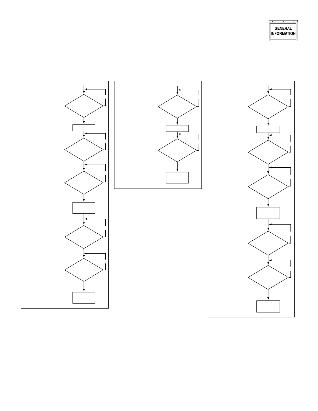
STARTING AND STOPPING - SEQUENCE DIAGRAMS
General Information
2-wire Remote Starting and
Stopping Sequence
Keyswitch in Auto Position
NOTE: Shutdown Alarms will
cause the engine to turn off
or not start.
Remote start
contacts
CLOSED?
Start the Engine
At
load accept
limits?
Warmup timer
expired?
Issue load
accept signal
Remote start
contacts
OPEN?
Exercise without transfer
starting and stopping sequence
NO
keyswitch in auto position.
NOTE: Shutdown Alarms will
NO
cause the engine to turn off
or not start.
NOTE: A Remote Start signal
will terminate exercise and
proceed to normal running mode.
NO
NO
Time to
exercise?
Start the Engine
Exercise
time
expired?
Stop the Engine
Loss of utility with HTS
starting and stopping
NO
sequence keyswitch in
auto position.
NOTE: Shutdown Alarms will
cause the engine to turn off
or not start.
NO
HTS indicates
loss of Utility?
Start the Engine
At
load accept
limits?
Warmup timer
expired?
Command HTS
to transfer to
Generator Power
HTS indicates
return of
Utility?
NO
NO
NO
NO
Cooldown
timer expired?
Stop the Engine
NO
NO
Cooldown
timer expired?
Stop the Engine
7
Page 10

General Information
H-100 Control Panel Technical Manual
VOLTAGE REGULATOR (OPTION)
All panels include automatic voltage regulation as
standard. There are various settings that can be
made to the voltage regulator via GenLink. The settings are normally factory preset and are shown here
for completeness.
Voltage KP/KI/KD — Voltage regulation stability
•
constants.
PMG — YES indicates a Permanent Magnet Excited
•
alternator.
VF Corner 1 / 2. — These are used for v/f control
•
to reduce the output voltage when a large load is
applied that slows down the generator. If the frequency drops below these setpoints, the voltage
is reduced proportionally as the frequency drops
according to the Volts per Hertz ratio.
Panel Type — Indicates the panel type that the H-
•
100 Control Panel has been programmed to be. It
will normally be H-100.
Volts per Hertz — Number of volts to reduce the
•
generator voltage for each hertz below VF Corner
1 frequency.
AVR Dump Improve — Makes the regulator mod-
•
ule increase the gain temporarily on a load dump
to improve the transient voltage response.
Unit Rated Power — This is the generator’s rated
•
power in kW.
Voltage Regulator (Option) Chart
NO. PARAMETER UNITS
1 Voltage KP -
2 Voltage KI -
3 Voltage KD -
4 PMG Y/N
5 VF Corner 1 Hertz
6 VF Corner 2 Hertz
7 Panel Type -
8 Volts per Hertz V/Hertz
9 AVR Dump Improve Y/N
10 Unit Rated Power kW
GOVERNOR (SPEED REGULATOR)
OPTION
All panels include automatic frequency (speed) regulation as standard. There are various settings that
can be adjusted for the governor via GenLink, these
include the target frequency. The settings are normally factory preset and are shown here for completeness, they do not apply to all governor types.
Standby KP,KI,KD — Frequency regulation stability
•
constants used for normal mode operation.
QuietTest® KP,KI,KD — Frequency regulation sta-
•
bility constants used for QuietTest® mode operation.
Actuator Type — Indicates the type of governor
•
actuator. The following types are available:
- POWERFLOW — Barber Coleman Powerflow,
voltage driven without position feedback
- BOSCH GAS — Bosch Butterfly, current driven
with position feedback
- LINEAR CURRENT — Linear, Current Driven
without position feedback
- DETROIT DIESEL — Detroit diesel PWM Driven
- BOSCH HORIZONTAL DIESEL — Bosch Diesel
Arm with Horizontal Connecting Rod and current
driven with position feedback
- BOSCH VERTICAL DIESEL — Bosch Diesel Arm
with Vertical Connecting Rod and current driven
with position feedback
Actuator Offset — Number corresponding to lowest
•
actuator position (Close Throttle).
Actuator Fullscale — Number corresponding to
•
highest actuator position (Open Throttle).
Actuator Normal Start Position — The position
•
the actuator will be parked at from start up until
the “Start detection RPM” is reached. If “soft start”
is enabled, this is also the maximum position of
the throttle until the Target Frequency - 3 Hz is
reached. Therefore, if “soft start” is enabled, the
actuator start position MUST be high enough to
reach, Target Frequency - 3 Hz.
Actuator QuietTest® Start Position — The position
•
the actuator will be parked at from start up until
the “Start detection RPM” is reached. If “soft start”
is enabled, this is also the maximum position of the
throttle until the QuietTest® Target Frequency - 3
Hz is reached. Therefore, if “soft start” is enabled,
the actuator start position MUST be high enough
to reach, QuietTest® Target Frequency - 3 Hz.
Soft Start Time — The time to stay at each soft
•
start step before moving on to the next step. ( Only
applies if soft start is enabled ).
Soft Start Frequency — An entry of 0 Hz disables
•
soft start. Any other value enables soft start which
ramps up the generator frequency at a rate determined by “Soft Start Time” to minimize smoke.
This value selects the first frequency to target after
start up. Once this frequency is attained, the generator will hold this frequency for the “Soft Start
Time” and then move to the next step. Each step
is 3 Hz higher with the final step being “Target
Frequency” - 3 Hz. Each step is held for the “Soft
Start Time”. During soft start, the throttle will not
be allowed to exceed the “Actuator Start Position”.
Diesel — Indicates if this is a diesel powered gen-
•
erator. This modifies such features as frequency
control, and others.
8
Page 11

Dump Enable — Indicates if extra load dump gov-
•
ernor compensation is desired to reduce increase
in frequency caused by drop in load. The following
three selections are available:
- No Dump — No additional compensation.
- Dump — Reset governor algorithm when load
dump detected.
- Dump & Hold — Same as Dump, but also hold
throttle closed until frequency back in range.
Engine Linearization — Selects engine torque
•
to actuator position translation curve for Bosch
Actuators.
0 = No conversion - torque = position
1 = Butterfly Actuator with minimum position
same as unpowered actuator
2 = Diesel arm with Horizontal rod
3 = Diesel arm with Vertical rod
4 = Same as 1, but minimum position at actuator
mechanical stop
5 = Same as 4, but with limited position resolu-
tion of 1
6 = Same as 4, but with added energy to accom-
modate throttles that normally operate in the
nearly closed position at no load
Integral limit/Antiwindup — Choose whether to use
•
an integral limit or an anti-windup strategy.
YES = integral limit
NO = anti-windup
Limit/windup parameter — If “Integral Limit” is
•
selected, this is the maximum value the integral
is allowed. If “Anti-Windup” is selected, this is the
integral value above which the anti-windup algorithm becomes active.
Pwm Counts per ampx10 — Number of PWM
•
counts required to drive one tenth of an amp into
a linear current driven actuator. This only applies
to the “Linear Current” actuator type.
Desynch Offset — Offset of –0.9 to +0.9 Hertz to be
•
applied to the target frequency to improve passive
synchronizing by Automatic Transfer Switches. If
an in-phase or synchronized transfer is required,
use this setting to adjust the generator frequency
to 0.1 Hz above nominal Utility frequency.
General Information
H-100 Control Panel Technical Manual
Governor (Speed Regulator) Option Chart
NO. PARAMETER UNITS
1 Standby KP -
2 Standby KI -
3 Standby KD -
4 QuietTest® KP -
5 QuietTest® KI -
6 QuietTest® KD -
7 Actuator Type -
8 Actuator Offset -
9 Actuator Fullscale -
10 Actuator Normal Start Position -
11 Actuator QuietTest® Start Position -
12 Soft Start Time Seconds
13 Soft Start Frequency Hz
14 Diesel Y/N
15 Dump Enable -
16 Engine Linearization -
17 Integral limit/Antiwindup Y/N
18 Limit / windup parameter -
19 Pwm Counts per ampx10 -
20 Desynch Offset Hz
TRENDING
Just like in the PM-DCP, there are two types of trending available - Remote and Local.
REMOTE TRENDING
GenLink performs remote trending by polling the
controller for the selected data at the desired rate.
Up to 8 analog channels can be monitored at a 0.3
second rate. If a faster rate is desired, reducing the
number of analog channels monitored will allow for a
0.1 second rate. The polling rate can be varied from
0.1 seconds to several hours. GenLink can save the
data to a file and/or display it as a near real-time
graph. The file is MS Excel compatible ( CSV format
). Examples of things you can trend are the generator
frequency response (in 0.1 second steps) to a block
load or Generated power over a day.
9
Page 12

General Information
H-100 Control Panel Technical Manual
LOCAL TRENDING
Local trending is done inside the controller where up
to 1000 samples can be stored in memory. GenLink
provides an interface to select the analog channels to
be trended, the rate to be sampled at, and optional
triggers to be used to specify when to sample. Up to 6
analog channels can be sampled. However, the 1000
samples are divided by the number of channels. For
example, there will be 1000 samples of 1 channel or
only 166 samples of each of 6 channels. The analog
samples can be sampled at one of three basic polling
rates: Low Speed, Mid Speed, and High Speed. For
the Low Speed and Mid Speed modes, there are also
several settings that can be used to determine when
to sample. GenLink can save the data to a file and/or
display it as a snap-shot graph. The file is MS Excel
compatible ( CSV format ).
GENLINK LOCAL TRENDING SETUP
When setting up the local trending, verify that the
“Armed” box is unchecked and press “Apply”. To
change the settings with the trending armed may
result in corrupted data. Select a rate at which to
take samples.
Low Speed rate samples the processed analog
•
channel values at a rate that is able to be set in
increments of 0.1 seconds.
Mid Speed rate is about 2 milliseconds which
•
captures the new analog channel value as soon
as it is processed by the measurement and alarm
modules.
High Speed rate is 0.4 milliseconds and is reserved
•
for the raw AC wave forms of generator voltage and
current.
There are 6 pull-down boxes that allow the selection of
up to 6 analog channels. All channel pull-down boxes
after the first pull-down box with NULL CHANNEL
selected are ignored. If High Speed is selected, the
pull-down boxes are not used. Instead, there are 6
check boxes that can be used to select which voltage
and current lines are to be trended.
The “Capture When” pull-down box allows the trending to be limited to the engine running or engine being
stopped. If the “Stop at End of Buffer” box is selected,
then the trending will start when the “Capture When”
condition is true and stop when the 1000 samples
have been taken.
Any digital or analog channel can be used as an event
trigger. The event trigger needs to be set up in that
channel's setup screen. Checking the “Capture Only
When Trigger is True” box will cause the samples to
only be taken while the event trigger is true. Checking
the “Capture on Shutdown Alarm” will cause the samples to start upon the setting of a shutdown alarm.
The event trigger can be used to start sampling, stop
sampling, or center the sampling by selecting the
appropriate radio button:
10
No Trigger
The event trigger is ignored and samples are continually being placed into the buffer.
Pre-Trigger
Samples are continually being placed into the buffer
until the event trigger becomes true. Then no more
samples are placed into the buffer.
Post-Trigger
No samples are placed into the buffer until the event
trigger becomes true. Then samples are placed in the
buffer until it is full.
Pre- and Post-Trigger
Samples are continually being placed in the buffer
until the event trigger becomes true. This point is
considered ½ of the buffer. Samples continue to be
placed into the buffer until it is full.
Pressing the “View” button will show a graph of
the samples in the buffer at the time the button is
pressed. The graph has a “Save” button that allows
the user to save the data out to a file in a MS Excel
compatible ( CSV ) format.
THE ILC
The built-in ILC uses simple combinatorial logic to
generate digital outputs and limited generator control. The ILC uses ladder logic for programming,
and a separate offline programming tool is available to generate the ILC programs. These are then
downloaded via GenLink and are started or stopped
by means of a checkbox on the GenLink ILC page.
Once downloaded and started, they will remain active
unless they are stopped via GenLink, even if power
is cycled.
The I/O scan time of the ILC is about 100 ms worst
case. This means that all inputs and outputs are
scanned within 100 ms. Also, the ILC processes
one rung every 5 ms, so 5 rungs will take 25 ms.
However, this is in parallel with the I/O scan and not
added to it.
The offline tool uses graphic symbols to design the
“rungs” of the ladder logic. The rungs are simple and
can only have 2 combinatorial elements in them, but
by the use of “soft contacts” the output of one rung
can be fed into the input of another to provide more
combinations. As well as the logical combinations,
there are also analog comparisons, counters and timers available for use in the rungs. As an example this
allows the following type of logic to be built:
IF (in automatic) AND (engine running) AND (air
temperature >25 deg) FOR (20 seconds) THEN
OPERATE (output 7).
Page 13
General Information
H-100 Control Panel Technical Manual
Generator control is limited to the following output
options (referred to as “Hooks”).
1. Use Keyswitch
2. Force Off – cleared with “Use Keyswitch” hook
3. Force Manual – cleared with “Use Keyswitch”
hook
4. Force Auto – cleared with “Use Keyswitch” hook
5. Force Dialout
6. Halt ILC
7. Force Alarm/Warning #1
8. Force Alarm/Warning #2
9. Force Remote Start
For detail in programming the ILC, refer to the ILC
manual.
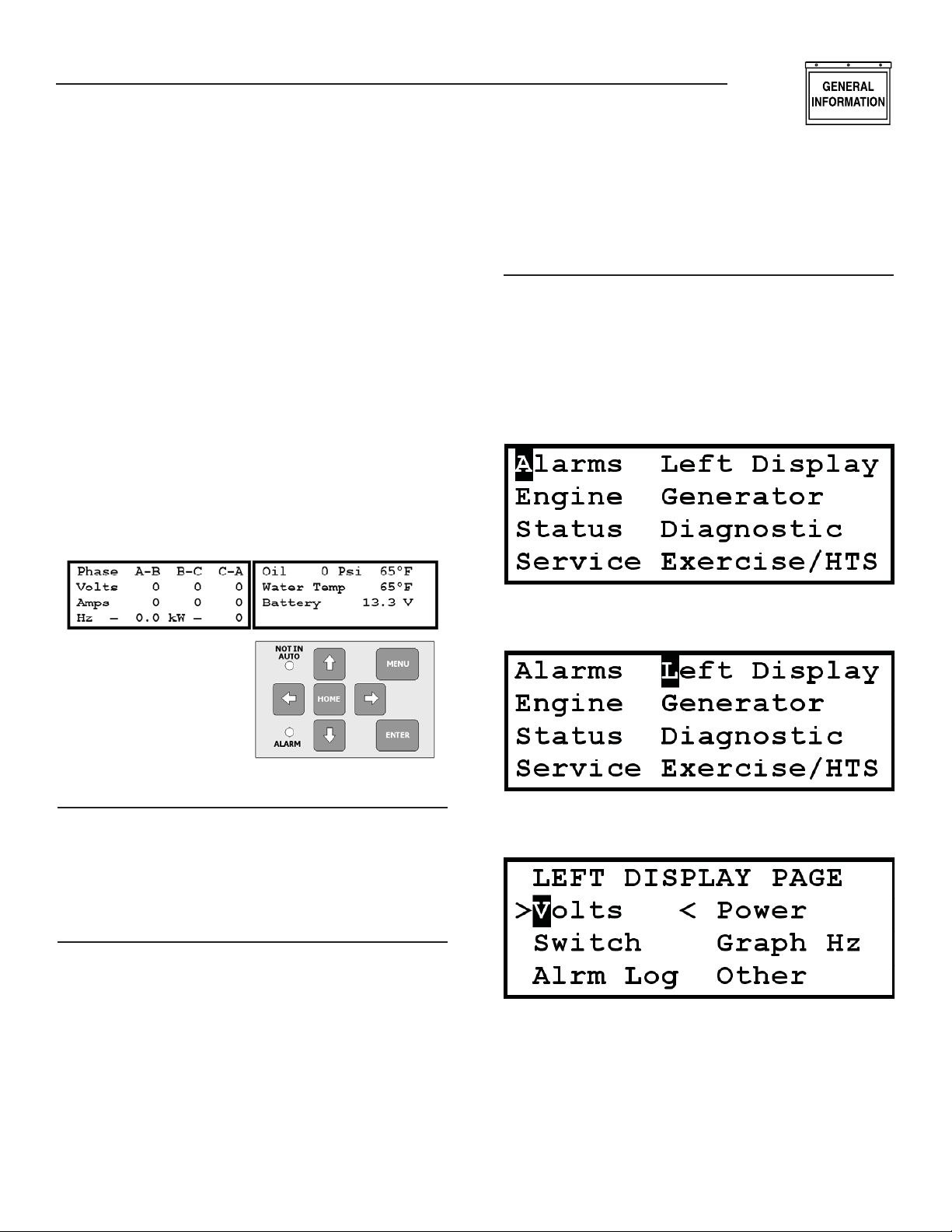
THE FRONT PANEL DISPLAY
The front panel display consists of two LCD displays
that are 4 rows of 20 characters each and a key pad
with seven buttons and two LEDs.
field. Moving off an edit field while in edit mode automatically enters the value displayed. Also, while in
edit mode, pressing the Home button will return the
parameter to the last value entered.
LEFT DISPLAY PAGES
The left display has five “fixed” parameter pages:
System Voltages, System Power, Transfer Switch
Mimic Diagram, Generator Frequency Graph, and
System Alarm Log. A sixth page is selectable, but has
no function at this time. The left display page is determined by selecting the right display menu item, “Left
Display”. To change the left display, do the following:
Press the “MENU” button.
Press the button to move to the “Left Display”
field.
LEFT DISPLAY
The left display is used to display a “fixed” set of
parameter pages and has no cursor or entry fields.
The key pad has no direct control of its contents. Its
contents are determined by a menu selection on the
right display.
RIGHT DISPLAY
The right display has several pages and responds
directly to the key pad. There are two “quick” buttons
on the key pad that are used to go directly to either
the Home page or the Menu page. The Enter button
is used to enter and exit edit mode, operate an output override, or select another page. When not in edit
mode, the arrow buttons are used to navigate around
the page to either an edit field or a control field.
When in edit mode, the up/down buttons slew up or
down through the available values and the right/left
buttons are used to change to a different digit or edit
Press the “ENTER” button to display the “Left
Display” menu page.
The “>…..<” indicates which page is currently displayed on the left display. Use the arrow buttons to
move the cursor to the desired page name and press
the “ENTER” button. The left display will change
to the new page and the “>…..<” will move to the
selected page name.
11
Page 14
General Information
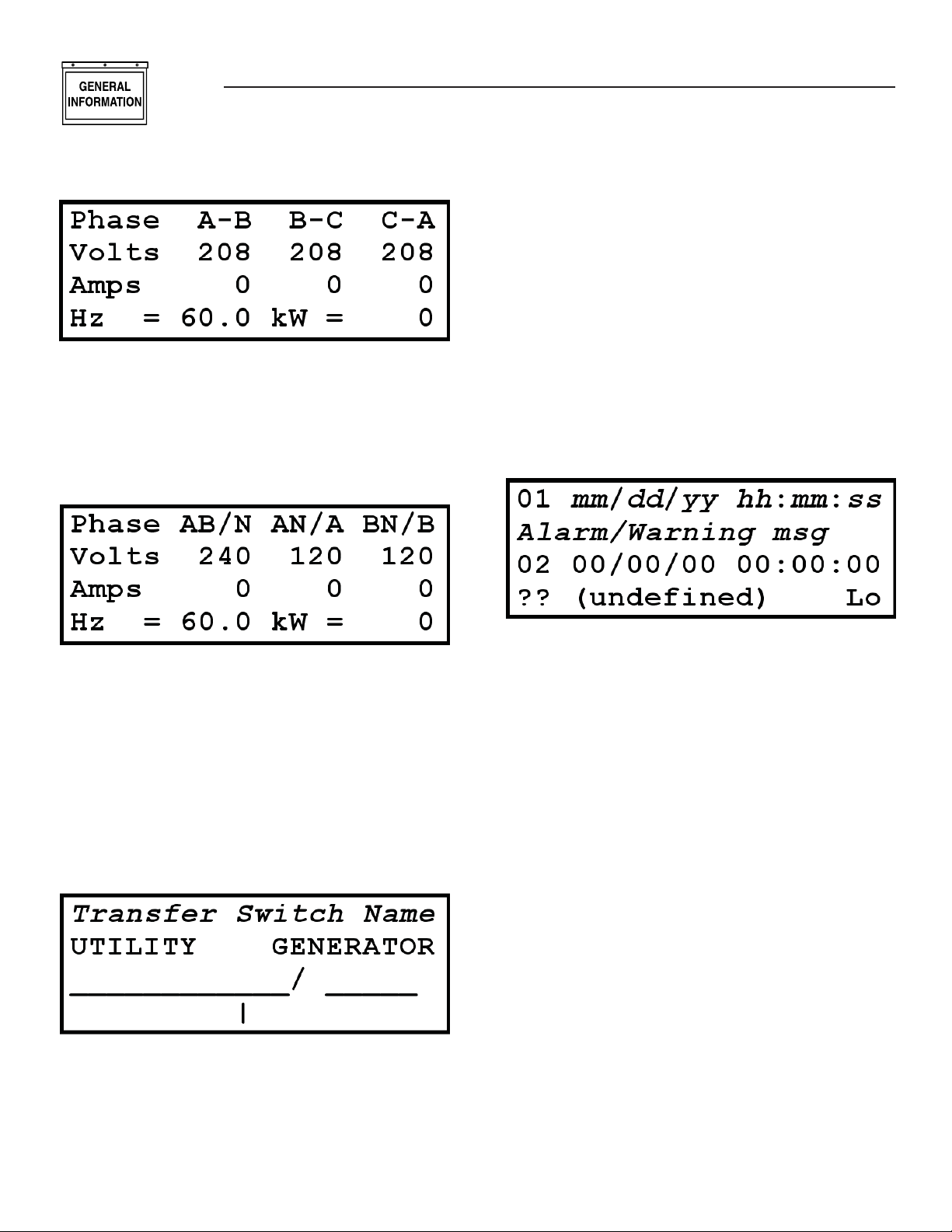
H-100 Control Panel Technical Manual
> Volts <
This is a typical three phase System Voltages page.
LINE 1: Phase titles for the voltage and current.
LINE 2: Line-to-line voltages in Volts RMS.
LINE 3: Line currents in Amps RMS.
LINE 4: Generator frequency in Hz and total system
power in kilowatts.
LINE 1: “Transfer Switch Name” indicates which
switch inputs are being displayed such as “From
HTS #1”. To select a switch to display, select the
switch number on the HTS page (refer to the Right
Display Pages - Exercise/HTS page). If there are
no HTS switches connected, then the Line Power
and Generator Power inputs are displayed and the
“Transfer Switch Name” is “From Line/Gen Inputs”
LINE 2: Title line showing the left side is the Utility
switch and the right side is the Generator switch.
LINE 3: Character graphics showing the switch
states – open or closed.
LINE 4: Character graphics indicating the load coming off the bottom of the diagram.
> Alrm Log <
This is a typical single phase System Voltages page.
LINE 1: Phase titles for the voltage and current
– voltage title/current title.
LINE 2: Line-to-line voltage for AB and Line-toNeutral voltage for A and B in Volts RMS.
LINE 3: Neutral current and Line currents in Amps
RMS.
LINE 4: Generator frequency in Hz and total system
power in kilowatts.
> Switch <
This is the Transfer Switch Mimic Diagram page.
It shows the position of the Utility Switch and the
Generator Switch. This depicted display shows the
Utility switch closed and the Generator switch open.
There can be up to 4 HTS switches connected to the
generator.
This is the System Alarm Log page. It displays the last
20 alarms or warnings that occurred with a time and
date stamp. Two records are displayed at a time.
LINE 1/3: The record’s alarm or warning number
(lowest number being the most recent) followed by the
date and time that the alarm or warning occurred.
LINE 2/4: The alarm or warning description message. The depicted display shows a basic format in
place of the first record and an empty record for the
second. The records scroll up at about a 4 second
rate.
The message format symbols are explained below:
First 2 characters:
?? – Empty slot
Wr – Warning
Al – Non-shutdown alarm
SD – Shutdown alarm
Last 2 Characters:
Sn – Sensor failure
Hi – Tripped by being greater than threshold
Lo – Tripped by being less than threshold
– (blank) Internal alarm or warning
12
Page 15
General Information
H-100 Control Panel Technical Manual
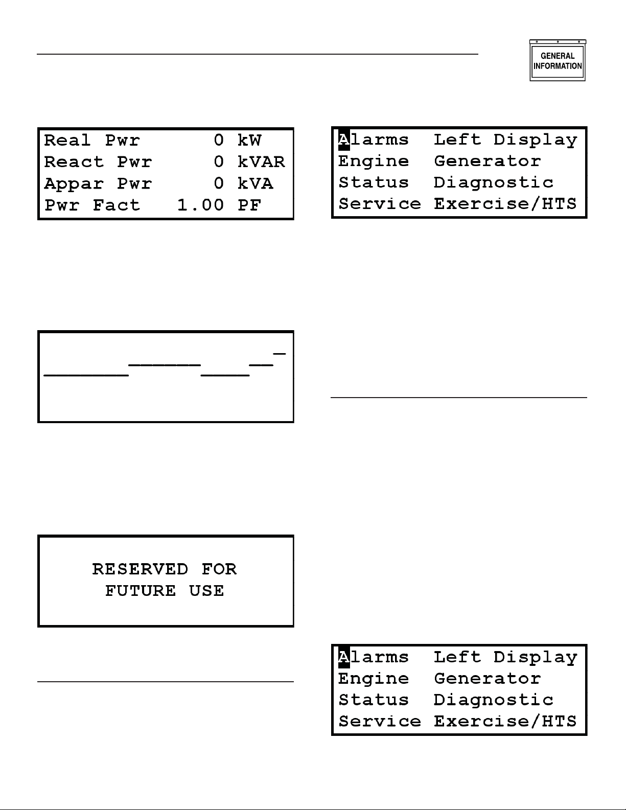
> Power <
This is a typical System Power page.
LINE 1: Total system real power in kW.
LINE 2: Total system reactive power in kVAR.
LINE 3: Total system apparent power in kVA.
LINE 4: Total system power factor.
> Graph Hz <
This is the Generator Frequency Graph page. This
graph provides a coarse representation of the generator frequency. The graph scrolls from right to left at 2
characters per second (last 10 seconds of data on the
display). The bottom of the graph is 50 Hz and the
top is 70 Hz. There are 32 levels between bottom and
top. Therefore, each level is approximately 0.6 Hz.
> Other <
This is the Other page. At this time, it has no function
and serves as a place holder.
Press the “MENU” button:
Use the arrow keys to move the cursor to the desired
menu item and then press the “ENTER” button. Most
menu items have multiple pages under them. When
that is the case, there is a “More (x-y)” field at
the lower right hand corner of the page where “x” is
the page number and “y” is the total number of pages
available under this menu item. To move forward or
backward through the pages, the cursor is placed
on the or character using the arrow buttons
and the “ENTER” button is pressed. When a page is
first displayed, the cursor normally starts on the
character to promote ease of scanning through the
pages.
ALARMS
There are three System Alarm and Warning pages.
Each page is capable of displaying three alarms or
warnings. If there are more than nine total alarms
and warnings to list, then only the most recent nine
will be visible. All alarms and warnings remain in the
list until they are cleared. Warnings clear when they
are no longer active. Normal Alarms clear when they
are no longer active and have been acknowledged.
Shutdown alarms clear only after the key switch has
been placed in the OFF position and they are no longer active. There are a few shutdown alarms that will
only clear after a power cycle of the controller and
they are no longer active. Besides using the menu to
get to the alarm pages, the right display immediately
changes to the first alarm page when an alarm or
warning first becomes active. If a shutdown alarm is
active and an alarm or warning is not acknowledged,
the displays will flash with the Alarm LED.
Do the following to view the alarm/warnings pages:
Press the “MENU” button.
RIGHT DISPLAY PAGES
The right display is menu based with eight main menu
items: System Alarm and Warning pages, Engine
Parameter pages, System Status pages, Maintenance
Status Pages, Left Display Menu page, Generator
Parameter pages, System Diagnostic pages, and
Internal Exercise and HTS pages. To select a page for
the right display, do the following:
13
Page 16
General Information
H-100 Control Panel Technical Manual
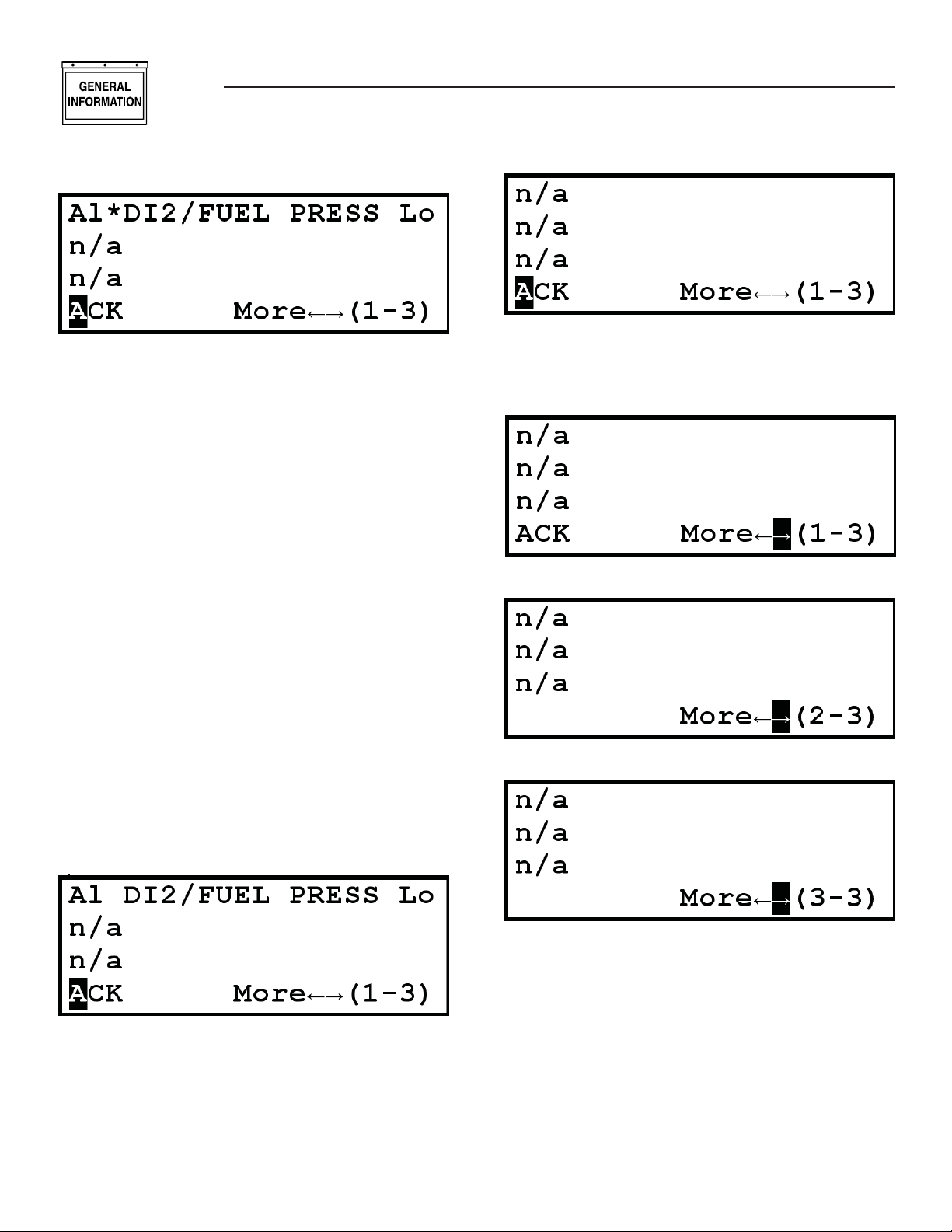
Press the “ENTER” button.
This is a typical System Alarm and Warning page.
The n/a indicates there is not an alarm or warning
to display on that line. As depicted, this display indicates a Fuel Pressure alarm for low pressure. This
would be a common alarm for a system that has the
gas line turned off. The “Al” indicates it is an alarm.
The “*” indicates the alarm has not been acknowledged. The “DI2/FUEL PRESS” message indicates it
is a fuel pressure alarm (DI2 was included in the text
by the user to indicate it is Digital Input #2). The “Lo”
indicates the alarm was tripped because the input
value fell below a set threshold.
The message format symbols are explained below:
First 2 characters:
Wr – Warning
Al – Non-shutdown alarm
SD – Shutdown alarm
Third Character:
* – Has not been acknowledged
Last 2 Characters:
Sn – Sensor failure
Hi – Tripped by being greater than threshold
Lo – Tripped by being less than threshold
(blank) – Internal alarm or warning
Press the “ENTER” button while the cursor is on
"ACK" to acknowledge the alarm.
The alarm has cleared since the gas pressure is now
adequate.
Move the cursor to the on the bottom line by pressing the button twice or the button once.
Press the “ENTER” button to see the next page.
Press the “ENTER” button to see the next page.
The “*” is now gone since the alarm has been
acknowledged.
Turn the gas line on.
14
ENGINE
There are four Engine Parameter pages. In most H100 Control Panels, there are spare analog channels
available or unused analog channels. They can be
displayed on these pages. If they are not configured,
they will not be displayed.
Do the following to view the engine parameter pages:
Press the “MENU” button.
Page 17

Press the button.
Press the “ENTER” button.
General Information
H-100 Control Panel Technical Manual
This is a typical second engine parameter page. The
first two values on this page are not able to be configured as other values.
LINE 1: Engine RPM
LINE 2: Battery Voltage in Volts DC.
If any of these signals are not configured, they will
display “n/a” for their value.
LINE 3: Normally Battery Charger Current (Analog
Channel #9). If it is not configured, the line will be
blank.
LINE 4: “More” field to allow page selection.
Press the “ENTER” button.
This is a typical first engine parameter page. The
three values on this page are not able to be configured
as other values.
LINE 1: Oil Temperature (Analog Channel #1) in
degrees Fahrenheit.
LINE 2: Oil Pressure (Analog Channel #3) in pounds
per square inch.
LINE 3: Coolant Temperature (Analog Channel #2)
in degrees Fahrenheit.
LINE 4: “More” field to allow page selection.
If any of these signals are not configured, they will display “n/a” for their value such as the Oil Temperature
shown above.
Press the “ENTER” button.
This is a typical third engine parameter page.
LINE 1: Total number of hours the engine has run.
LINE 2: Coolant Level Sensor (Analog Channel #4)
reading in steps 0 - 1023.
LINE 3: Often the Fuel Level Sensor (Analog Channel
#5) reading in %. As depicted, Analog Channel #5 is
not configured – leaving the line blank.
LINE 4: “More” field to allow page selection.
Press the “ENTER” button.
This is a typical fourth engine parameter page.
LINE 1: Auxiliary Analog Channel input (Analog
Channel #6).
LINE 2: Throttle Position Sensor (Analog Channel
#7) reading in steps 0 - 1023.
LINE 3: Emissions Sensor (Analog Channel #8)
reading. As depicted, Analog Channels #6 and #8 are
not configured – leaving the lines blank.
LINE 4: “More” field to allow page selection.
15
Page 18

General Information
H-100 Control Panel Technical Manual
STATUS
There are two System Status pages. These pages
show the system status, system time, and system
versions.
Do the following to view the system status pages:
Press the “MENU” button.
Press the button twice.
Press the “ENTER” button.
This is a typical first System Status page.
LINE 1: Engine Running Status. It can have the following values:
“Stopped, Key SW Off”
The engine is stopped and the key switch is in the
OFF position.
“Running from Manual”
The engine is starting or running and the key switch
is in the MANUAL position.
“Running from 2-wire”
The engine is starting or running because the 2-wire
start signal was activated and the key switch is in the
AUTO position.
“Running from serial”
The engine is starting or running because the GenLink
commanded it to start and the key switch is in the
AUTO position.
“Running exercise”
The engine is starting or running because internal
exercise was activated and the key switch is in the
AUTO position.
“Stopped, Key SW Auto”
The engine is stopped and the key switch is in the
AUTO position.
“Running, QuietTest”
The engine is starting or running because QuietTest®
was activated and the key switch is in the AUTO position.
“Running, HTS Xfer SW”
The engine is starting or running because the HTS(s)
indicated a need for the generator power and the key
switch is in the AUTO position.
LINE 2: Generator Status. It can have the following
values:
“Resetting”
The generator control system is resetting.
“Stopped”
Generator is stopped and not preheating.
“Stopped, Preheating “
Generator is stopped and preheating.
“Cranking”
Generator is starting and not preheating.
“Cranking, Preheating”
Generator is starting and preheating.
“Pause between starts”
Generator is pausing between consecutive start
attempts.
“Started,not to speed”
Generator is started, but has not attained normal
running speed yet.
“Warming, Alarms Off “
Generator is started and is up to speed, but is waiting
for warmup timer to expire.
“Warmed Up,Alarms Off ”
Generator is started and warmed up, but the hold-off
alarms are not yet enabled.
“Warming, Alarms On”
Generator is started and the hold-off alarms are
enabled, but is waiting for warmup timer to expire.
16
Page 19

General Information
H-100 Control Panel Technical Manual
“Warmed Up, Alarms On”
Generator is started, warmed up, and the hold-off
alarms are enabled.
“Running,cooling down”
Generator is still running, but waiting for cool down
timer to expire.
“Stopping”
Generator is running down after being turned off
normally.
“Stopping due to Alrm”
Generator is running down after being turned off due
to a shutdown alarm.
“Stopped due to Alarm”
Generator is stopped due to a shutdown alarm.
LINE 3: System Time and Date. It is able to be
changed on this page by using the arrow buttons to
go from field to field or to modify a field in edit mode
and the “ENTER” button to enter and exit edit mode.
There are five editable fields: Hours, Minutes, Month,
Day, and Year. The day of the week will change as the
displayed date is changed. See the “SET DATE AND
TIME” section of this manual for details.
LINE 4: “More” field to allow page selection.
Press the “ENTER” button.
SERVICE
There are four Maintenance Status pages. The first
three pages show the status of the scheduled maintenance items. The fourth page allows changing of the
display contrast.
Do the following to view the service pages:
Press the “MENU” button.
Press the button three times or the button
once.
Press the “ENTER” button.
This is a typical second System Status page.
LINE 1: Firmware and Hardware release versions.
LINE 2: Configuration File identifier – serial num-
ber, model number, or text.
LINE 3: ILC program name. This text string is blank
or blocks (as shown above) when there is no ILC
program loaded.
LINE 4: ILC program running status followed by the
“More” field to allow page selection.
This is a typical first Maintenance Status page. Each
line displays a maintenance item that has been set
up via GenLink. The value displayed is the approximate % of life remaining before maintenance should
be performed. Refer to the Maintenance setup using
GenLink.
Press the “ENTER” button.
This is a typical second Maintenance Status page.
17
Page 20

General Information
H-100 Control Panel Technical Manual
Each line displays a maintenance item that has
been set up via GenLink. The value displayed is the
approximate % of life remaining before maintenance
should be performed. Refer to the Maintenance setup
using GenLink.
Press the “ENTER” button.
This is a typical third Maintenance Status page. Each
line displays a maintenance item that has been set
up via GenLink. The value displayed is the approximate % of life remaining before maintenance should
be performed. Refer to the Maintenance setup using
GenLink.
Press the “ENTER” button.
Press the button and then the button.
Press the “ENTER” button.
This is a typical fourth Maintenance Status page. The
first line is the display contrast. The display contrast
is able to be changed on this page. However, changing
this setting can result in the display becoming nonreadable. Use caution. Use the arrow buttons to go to
the contrast field. Press the “ENTER” button to enter
edit mode. Use the arrow buttons to change the contrast value (range is 00 to 37). Pressing the “HOME”
button while in edit mode will return the value to the
last entered value. Press the “ENTER” button to exit
edit mode.
GENERATOR
There are three Generator Parameter pages – voltage
parameters, power parameters, and i2t parameters.
Do the following to view the generator parameter
pages:
Press the “MENU” button.
This is a typical first Generator Parameter page for a
three phase system.
LINE 1: Phase titles for the voltage and current.
LINE 2: Line-to-Line voltages in Volts RMS.
LINE 3: Line currents in Amps RMS.
LINE 4: Generator frequency in Hz followed by the
“More” field to allow page selection.
The voltages can be converted to values representing
the line-to-neutral voltages by changing the title line
(first line) using edit mode. Use the arrow buttons
to move to one of the title fields – A-B, B-C, or C-A.
Press the “ENTER” button to enter edit mode. Use
the up or down arrow button to change the display to
A-N, B-N, and C-N. Press the “ENTER” button to exit
edit mode. The same process is followed to return to
line-to-line displays. This also affects the left display
voltage page.
18
Page 21

This is a typical first Generator Parameter page for a
single phase system.
LINE 1: Phase titles for the voltage and current
– voltage title/current title.
LINE 2: Line-to-Line voltage for AB and Line-toNeutral voltage for A and B in Volts RMS.
LINE 3: Neutral current and Line currents in Amps
RMS.
LINE 4: Generator frequency in Hz followed by the
“More” field to allow page selection.
Press the “ENTER” button.
This is a typical second Generator Parameter page for
a three phase system.
LINE 1: Total system real power in kW.
LINE 2: Total system power factor.
LINE 3: Percentage of the system rated power being
used.
LINE 4: The “More” field to allow page selection.
General Information
H-100 Control Panel Technical Manual
This is a typical third Generator Parameters page. It
graphically displays the percent of i2t thermal limit
currently attained. If the limit is exceeded, an alarm
will be set and the generator will shutdown to protect
the alternator. This display will then show % Temp
>Over Limit<”. GenLink can provide more information regarding actual limits exceeded. This page is
disabled if the i2t function is disabled.
DIAGNOSTICS
There are six System Diagnostic pages. They are digital inputs page, digital outputs page, two analog input
pages, RS-232 communications status page, and RS485 communications status page.
Do the following to view the diagnostics pages:
Press the “MENU” button.
This is a typical second Generator Parameter page for
a single phase system.
LINE 1: Phase titles for the power and power factor
– Total, A-Neutral, B-Neutral.
LINE 2: Real power in kW – Total system, A-Neutral,
B-Neutral.
LINE 3: Power Factor – Total system, A-Neutral, BNeutral.
LINE 4: The “More” field to allow page selection.
Press the “ENTER” button.
Press the button twice and the button.
Press the “ENTER” button.
19
Page 22

General Information
H-100 Control Panel Technical Manual
This is a typical first System Diagnostics page. It displays ten of the discrete inputs into the H-100 Control
Panel. Inputs to the controller are internally pulled
to 5 v, so to activate an input you must short it to
ground.The following names are normally assigned
to these inputs:
#1 Key switch in AUTO position
#2 Key switch in MANUAL position
#3 Emergency Stop Active
#4 Remote 2-wire start Active
#5 Battery Charger Failure
#6 Rupture Basin or Low Fuel Pressure
#7 Transfer Switch in Line Power Position
#8 Transfer Switch in Emergency Power Position
#9 Modem is connecting or connected
#10 Modem is present
Press the “ENTER” button.
This is a typical second System Diagnostics page.
It displays ten of the discrete outputs out of the H100 Control Panel. Outputs from the controller are
generally open collector. This means that they sink
current through a load and you will NOT see any voltage change on them when they are activated, unless
they are connected to a load. These outputs can be
temporarily inverted from this page. Extreme caution
should be exercised while inverting outputs since it
can result in operation of starters, fuel solenoids, etc.
To invert an output, use the arrow buttons to position
the cursor on the output value to be inverted. Press
the “ENTER” button. The output will be inverted for
approximately 2 seconds and then return to normal
control. Only one output can be inverted at a time and
leaving the page cancels all output inversions.
The following names are normally assigned to these
outputs:
#1 Key switch in AUTO position
#1 Activate Starter Relay
#2 Activate Fuel Relay
#3 Activate Alarm/Warning Relay (Buzzer)
#4 Activate Gas Relay on 13.3L Engines
#5 Auxiliary Discrete Output #1
#6 Auxiliary Discrete Output #2
#7 Auxiliary Discrete Output #3
#8 Auxiliary Discrete Output #4
#9 Activate Ignition Module on 13.3L Engines
20
#12 Activate Emissions Module or Preheat
Press the “ENTER” button.
Press the “ENTER” button.
The above two pages are typical System Diagnostics
Analog Input pages. The analog channel values that
are displayed are the “raw” unprocessed data and
are 10 bit numbers ranging from 0 - 1023 representing a voltage or current on the analog input channel.
The following names are normally assigned to these
inputs:
PAGE 3-6 LINE 2:
#1 A current (CT1)
#2 B current (CT2)
#3 C current (only three phase) (CT3)
PAGE 3-6 LINE 3:
#4 A-B voltage (A-N if single phase) (Vsense1)
#5 B-C voltage (B-N if single phase) (Vsense2)
#6 C-A voltage (only three phase) (Vsense3)
PAGE 3-6 LINE 4:
#7 Oil Temperature (AN1)
PAGE 4-6 LINE 1:
#8 Coolant Temperature (AN2)
#9 Oil Pressure (AN3)
#10 Coolant Level (AN4)
PAGE 4-6 LINE 2:
#11 Fuel level (AN5)
#12 Auxiliary Analog Input (AN6)
#13 Throttle Position Sensor (AN7)
PAGE 4-6 LINE 3:
#14 Emissions Oxygen Sensor (AN8)
#15 Battery Charger Current (AN9)
#16 Battery Voltage
Page 23

General Information
H-100 Control Panel Technical Manual
Press the “ENTER” button.
Press the “ENTER” button.
The above two pages are typical of communications
diagnostics, one page for each port. The LCD display
will show four lines of information about the port:
LINE 1: Will show the type of port protocol that has
been selected. It will also show the Modbus address
(if appropriate) and whether the port is RS-232 or
RS-485.
LINE 2: Will show the settings for the port such as
baud rate, bits per character, stop bits, and parity.
LINE 3: Shows a live update of counts of messages
transmitted, received, and errors.
LINE 4: Shows a mimic of LED’s for TX, RX, and
ERR. For example, the TX LED lit (T*) means the H100 Control Panel is transmitting. Not lit (T-) means
it is not transmitting.
Press the button.
Press the “ENTER” button.
This is a typical first Internal Exercise and HTS
page.
LINE 1: Indicates if internal exercise is enabled. This
field is editable.
LINE 2: Day of week and time of day to start the
exercise weekly. These fields are editable.
LINE 3: How much time remains before exercise is
completed. It starts with 20 minutes.
LINE 4: The “More” field to allow page selection.
Press the “ENTER” button.
EXERCISE/HTS
There are four pages under this menu item – two for
internal exercise and two for HTS. This is where the
internal exercise can be setup and enabled (see the
Exercise Setup Using Front Panel section) and the
HTSs can be enabled and monitored.
Do the following to view the internal exercise and
HTS pages:
Press the “MENU” button.
This is a typical second Internal Exercise and HTS
page.
LINE 1: Indicates if QuietTest® is enabled. This field
is editable.
LINE 2: Can be used to start a 20 minute exercise
period right now. This field is editable.
LINE 3: Indicates if the HTS switches should be
exercised during normal exercise mode. This field is
editable.
LINE 4: The “More” field to allow page selection.
Press the “ENTER” button.
21
Page 24

General Information
H-100 Control Panel Technical Manual
This is a typical third Internal Exercise and HTS
page.
LINE 1: The left side shows the HTS switch number
that the data on this page applies to. This field is
editable in that switch numbers 1 – 4 can be selected.
The Switch number selected on this page also selects
the switch to use for the Left Display Switch Mimic
diagram if that switch is enabled. In addition, it is the
selected switch number for the next page, and for the
remote annunciator lights for generator power and
line power. The right side of the first line is the mode
that the HTS is in. It can have the following values:
“Disabled”
This switch is not present in the system.
“Enabled”
This switch is present in the system and operating
normally.
“Fast Test”
The “FAST TEST” button on the HTS has been
pressed and fast test is being executed.
“Norm Test”
The “TEST” button on the HTS has been pressed and
normal test is being executed.
“No Comms”
This switch is present in the system, but not communicating.
“Xfer Exer”
The system is running in exercise and is exercising
the HTS as well.
“Exercise”
The system is running in exercise, but is not exercising the HTS.
LINE 2: The left side is the status of the HTS. It can
have the following values:
“Idle”
HTS is waiting for conditions to change. No action is
being taken.
“Error”
HTS controller has detected an error.
“TDN”
22 22
HTS is in Time Delayed Neutral position.
“Synching”
HTS is waiting for Generator and Utility to become
synchronized before changing switch position.
“SB4 Xfer”
HTS has activated the “Signal Before Transfer” relay.
“Cls Gen SW”
HTS is closing the Generator side of the switch.
“Cls Util SW”
HTS is closing the Utility side of the switch.
“Opn Gen SW”
HTS is opening the Generator side of the switch.
“Opn Util SW”
HTS is opening the Utility side of the switch.
“No Utl/Coms”
HTS has detected loss of utility and communications
with the H-100 Control Panel.
“No Comms”
HTS has detected utility present, but loss of communications with the H-100 Control Panel.
“Pwr Cycled”
HTS has been power cycled and is awaiting reconfiguration commands from H-100 Control Panel.
“SW Disabled”
HTS indicates that it is disabled.
The right side is the Utility frequency from the HTS
in Hz.
LINE 3: The HTS backup battery voltage in Volts DC
followed by the Utility voltage from the HTS in Volts
RMS.
LINE 4: The HTS firmware version number followed
by the “More” field to allow page selection.
Press the “ENTER” button.
This is a typical fourth Internal Exercise and HTS
page. The left side of the first line shows the HTS
switch number that the data on this page applies to.
This field is editable in that switch numbers 1 – 4
can be selected. The Switch number selected on this
Page 25

General Information
H-100 Control Panel Technical Manual
page also selects the switch to use for the Left Display
Switch Mimic diagram if that switch is enabled. In
addition, it is the selected switch number for the previous page, and for the remote annunciator lights for
generator power and line power. The right side of the
first line is the enable state of the HTS. It is editable
and can have the following values:
“Disabled”
This HTS switch is not included in the system.
“Enabled”
This HTS switch is included in the system.
NOTE:
Enabling a switch that is not present will result
in a switch communications warning after a few
seconds and will switch the display to the Alarms
page.
HOME
Press the “HOME” button while not editing a field.
This is a typical Home page. The contents of this
page along with the contents of the default left display
page (Volts) were selected such that all the normally
desired data would be available for viewing at once.
LINE 1: Oil Pressure (Analog Channel #3) in pounds
per square inch followed by Oil Temperature (Analog
Channel #1) in degrees Fahrenheit.
LINE 2: Coolant Temperature (Analog Channel #2)
in degrees Fahrenheit.
LINE 3: Battery Voltage in Volts DC.
If any of these signals above are not configured,
they will display “n/a” for their value such as the Oil
Temperature shown above.
LINE 4: Often the Fuel Level Sensor (Analog Channel
#5) reading in percent. As depicted, Analog Channel
#5 is not configured – leaving the line blank.
ALARM LED output
COMMON ALARM output
AUTO/OFF/MAN KEYSWITCH input
NOT IN AUTO LED output
EMERGENCY STOP SWITCH input
The alarm LED will flash every second if a new alarm
occurs. Once this alarm is acknowledged via the
touch pad or GenLink, the LED will remain lit until
the alarm condition goes away. The LED will flash at
least once every 30 seconds to indicate the controller
is working properly.
The audible alarm will sound when a new alarm
occurs. It will be silenced when it is acknowledged.
The keyswitch in AUTO position allows the system to
start automatically, in OFF position prevents the system from operating, and in MANUAL position runs
the generator for test purposes only.
The “NOT IN AUTO” LED will flash every second if
the keyswitch is not in the AUTO position.
The EMERGENCY STOP switch will stop the generator and post an alarm.
THE ALARM LOG
The alarm log is a permanent (non volatile) store of
the last 20 alarms that occurred. If power is removed
from the controller, the log will be retained. When the
alarm log is full and a new alarm occurs, the oldest
alarm will be removed to create space for the new
one.
Each alarm is recorded along with a time/date stamp
and up to 6 optional measurements. Two of the six
measurements are fixed (via password protection) to
be coolant temperature and oil pressure.
The measurements you want to record are selected
from a pull down list in GenLink using the alarm/
event log menu, they can be analog inputs, digital
inputs or output functions. For example you can
record the generator voltages, frequency and the
state of the transfer switch when an alarm occurs.
The alarm log can be viewed via GenLink or the
left hand front panel display. Alarms are displayed
by GenLink in chronological order, the most recent
being at the top of the list.
All alarms/warnings and sensor failures are recorded
in the alarm log.
THE CONTROL PANEL
The H-100 Control Panel has some inputs and outputs which have been designated to be connected to a
standardized control panel. The format of the control
panel will vary from model to model and not all indicators may be present, however the following signals
are always available:
THE EVENT LOG
The event log is similar to the alarm log except that
the data is stored in temporary memory (volatile) and
will be lost if power is removed. The event log has
space to hold up to 20 events. When the event log is
full and a new event occurs, the oldest event will be
removed to create space for the new one.
23 23
Page 26

General Information
H-100 Control Panel Technical Manual
The event log, as its name implies, is designed to
store events which are programmable from GenLink.
Each measurement channel or output function can
be set as an event along with a setpoint. For example,
if you set Digital Input #1 (the keyswitch in AUTO
position) as an event with a setpoint of logical one,
each time the keyswitch is set in the auto position, an
event will be logged. Similarly you can set an analog
event with an analog setpoint and a comparison type.
For example you can set an event if the oil pressure
is less than 10 psi or if power output is greater than
100 kW.
Each event is recorded along with a time/date stamp
and up to 6 optional measurements. The measurements you want to record are selected from a pull
down list in GenLink using the alarm/event log menu.
They can be analog inputs, digital inputs or output
functions. The event log can only be displayed via
GenLink, it cannot be viewed on the front panel.
Events are displayed by GenLink in chronological
order, the most recent being at the top of the list.
MAINTENANCE SETTINGS
The controller provides a mechanism to generate
multiple warnings based on maintenance intervals.
Normally it will be shipped with these warnings
turned off. GenLink is used to enable these warnings by setting a maintenance interval for the alarm
of choice. The interval can be in engine run hours,
a specific engine run hour, number of operations, a
specific date or a combination of two of these methods. For example you can set the interval associated
with oil life to 6 months or 100 engine hours (whichever occurs first). The transfer switch is one example
of where a number of operations is relevant, spark
plug life is not.
To disable a maintenance warning, set the “mainte-
•
nance cycle” field to N/A.
To set a specific date, set the “installed at” setting
•
to the current date then set “End of life” to the
specific date.
To set a number of operations, set the “installed at”
•
setting to zero then set “End of life” to the number
of operations required.
To set a specific operation number (say at opera-
•
tion 500), set the “installed at” setting to the current number of operations, then set “End of life” to
the operation number.
To set a number of engine run hours, set the
•
“installed at” setting to zero then set “End of life”
to the number of engine hours required.
NEVER set the “Installed at” hours to anything
•
other than zero.
A warning is generated when the maintenance criteria are met. This warning can be cancelled by the
acknowledge button but will re-occur after 15 minutes. To permanently cancel the warning you must
reset the maintenance interval. This can only be done
via GenLink. The audible alarm will NOT sound for
each 15 minute re-occurrence of the warning after
the first maintenance warning is acknowledged.
The front panel display will show the percentage of
life left for each possible maintenance item.
AIR/FUEL RATIO CONTROL (OPTION)
With the addition of an oxygen sensor and a solenoid
to control the air fuel mix, the H-100 Control Panel
can perform air/fuel ratio control to provide an optimum (stochiometric) mix to reduce emissions. This
feature can be turned on or off via GenLink. The air
fuel solenoid output pin shares its function with the
preheat output. You must choose one of the two functions as follows:
To select air/fuel - set the “Diesel y/n” setting on the
•
governor page to “No”. Set preheat to “No”
To select preheat - set the “Diesel y/n” setting on the
•
governor page to “Y”. Set preheat to “Y”
I2T CURRENT MONITORING (OPTION)
Optionally the H-100 Control Panel can apply predictive firmware modeling to give I2T protection for
the rotor and stator assembly. Based on parameters
entered into the H-100 Control Panel via GenLink,
the firmware models the temperature rise and fall
of the alternator assembly and limits operation to
prevent it being damaged. The entered parameters
basically describe the thermal properties of each
alternator to the firmware. GenLink allows you to
choose the alternator model, and this automatically
downloads the appropriate parameters. The H-100
Control Panel will normally be delivered preprogrammed with the appropriate data . GenLink will
allow you turn this feature on or off as desired. There
is a GenLink display of the allowable temperature
limits for the selected alternator (2 limits, one for the
stator and one for the rotor) and also a display of the
predicted temperatures.
24
Page 27

INTERNAL EXERCISE FUNCTION
Generators best maintain their readiness by being
exercised once per week. This prevents the machine
from stagnating and provides an opportunity to discover any maintenance items that may need service
before the unit is actually needed for emergency
power. In the past, the generator had to be exercised
manually or an external exerciser was attached to the
generator or transfer switch to activate the remote
start once per week for a period of time long enough
for the generator to warm up. With the advent of QT
series of generators, that function was moved into
the generator controller. This allows the QT series
generator to have the QuietTest® mode of exercise as
one of its key features. Normal mode exercise can be
selected instead which can also exercise a Generac
Commercial Transfer Switch (HTS) if desired. These
features are all standard in the PowerManager® H100 controller, but require setup by the installer or
end user. The internal exercise can be set up using
GenLink or by using the front panel displays. This
section describes the procedures needed to perform
this setup.
The QuietTest® mode and Normal mode of exercise
run the generator for approximately 20 minutes
starting at a preset day and time once per week when
the key switch is in the AUTO position and internal
exercise is enabled. If the Normal exercise is used
with the option to exercise an HTS selected, the
exercise duration may vary based on the HTS settings. QuietTest® cannot exercise the HTS since the
lower generator frequency and voltage used to reduce
noise levels is incompatible with the standard system
loads.
If the generator is needed for emergency power while
exercise is running, exercise will be terminated automatically and the system will change to providing
emergency power.
NOTE:
If “transfer on exercise” is selected with an HTS
that is not a “Closed Transition Transfer Switch”,
there will be a momentary (possibly several seconds) interruption in power to the load when
switching from Utility to Emergency power and
when switching back. For this reason, “transfer on
exercise” is normally not selected.
General Information
H-100 Control Panel Technical Manual
Click on ”Select Exercise” to enable internal exercise
and allow the changing of the other exercise parameters.
QUIETTEST® SETUP USING GENLINK
Connect to the H-100 control panel. Using the
“Configuration” pull down, select “Exercise
Configuration” to display the Exercise Configuration
screen.
25
Page 28

General Information
H-100 Control Panel Technical Manual
Select the day of week to run the exercise.
Select the time of day to run exercise.
Click on “QuietTest®” to enable the exercise mode
with reduced sound levels. Press “Apply”.
Setup of QuietTest® is now complete. For this example, QuietTest® will start every Wednesday at 10:30
AM and run until about 10:50 AM
NORMAL EXERCISE SETUP USING
GENLINK
Connect to the H-100 control panel. Using the
“Configuration” pull down, select “Exercise
Configuration” to display the Exercise Configuration
screen.
Click on ”Select Exercise” to enable internal exercise
and allow the changing of the other exercise parameters.
Select the day of week to run the exercise.
26
Page 29

Select the time of day to run exercise.
General Information
H-100 Control Panel Technical Manual
QUIETTEST® SETUP USING FRONT
PANEL
Press the “MENU” button.
Move the cursor using the arrow keys to the Exercise/
HTS menu item.
Verify “QuietTest®” is not checked. Press “Apply”.
Setup of Normal exercise is now complete. For this
example, exercise will start every Wednesday at 10:30
AM and run until about 10:50 AM
If exercise of the HTS is desired, Click on “Transfer
on exercise” to enable transferring of the load to the
generator during exercise.
NOTE:
This feature is only available in non-QuietTest®
exercise and when an HTS is in the system.
Press the “ENTER” button.
Move the cursor to the “Exercise Enabled” field on
the first line.
Press the “ENTER” button to enter edit mode.
27
Page 30

General Information
H-100 Control Panel Technical Manual
Use the up and down arrow keys until a “Y” appears
in the field.
Press the “ENTER” button to exit edit mode.
Move the cursor to the “Time Start” day of week field
on the second line.
Press the "ENTER" button to exit edit mode.
Move the cursor to the “Time Start” time of day hours
field on the second line.
Press the “ENTER” button to enter edit mode.
Press the “ENTER” button to enter edit mode.
Use the up and down arrow key until the desired day
of the week is displayed.
28
Use the up and down arrow key until the desired
hour of the day is displayed.
NOTE:
In a number field the up/down arrows move the
digit up and down while the left/right arrows move
to the adjacent digit.
Press the “ENTER” button to exit edit mode.
Page 31

Move the cursor to the “Time Start” time of day minutes field on the second line.
Press the “ENTER” button to enter edit mode.
General Information
H-100 Control Panel Technical Manual
Move the cursor to the “QuietTest Selected” field on
the first line.
Use the up and down arrow key until the desired
minute of the hour is displayed.
Press the “ENTER” button to exit edit mode.
Move the cursor to the on the bottom line.
Press the “ENTER” button to enter edit mode.
Use the up and down arrow key until a “Y” appears.
Press the “ENTER” button to exit edit mode.
Press the “ENTER” button to move to the second
page.
NOTE:
Verify that “Xfer On Exercise” field is an “N”.
Otherwise, QuietTest® will be overridden with
normal exercise.
29
Page 32

General Information
H-100 Control Panel Technical Manual
Setup of QuietTest® is now complete. For this example, QuietTest® will start every Wednesday at 10:30
AM and run until about 10:50 AM
While QuietTest® is running, the “Time Remaining”
will display the approximate number of minutes left
before QuietTest® is completed.
NORMAL EXERCISE SETUP USING
FRONT PANEL
Press the “MENU” button.
Press the “ENTER” button to enter edit mode.
Use the up and down arrow keys until a “Y” appears
in the field.
Move the cursor using the arrow keys to the Exercise/
HTS menu item.
Press the “ENTER” button.
Move the cursor to the “Exercise Enabled” field on
the first line.
Press the “ENTER” button to exit edit mode.
Move the cursor to the “Time Start” day of week field
on the second line.
Press the “ENTER” button to enter edit mode.
30
Page 33

Use the up and down arrow key until the desired day
of the week is displayed.
General Information
H-100 Control Panel Technical Manual
NOTE:
In a number field the up/down arrows move the
digit up and down while the left/right arrows move
to the adjacent digit.
Press the “ENTER” button to exit edit mode.
Press the "ENTER" button to exit edit mode.
Move the cursor to the “Time Start” time of day hours
field on the second line.
Press the “ENTER” button to enter edit mode.
Move the cursor to the “Time Start” time of day minutes field on the second line.
Press the “ENTER” button to enter edit mode.
Use the up and down arrow key until the desired
minute of the hour is displayed.
Use the up and down arrow key until the desired
hour of the day is displayed.
31
Page 34

General Information
H-100 Control Panel Technical Manual
Press the “ENTER” button to exit edit mode.
Move the cursor to the on the bottom line.
Press the “ENTER” button to move to the second
page.
Use the up and down arrow key until a “N” appears.
Press the “ENTER” button to exit edit mode.
Setup of Normal Exercise is now complete. For this
example, exercise will start every Wednesday at 10:30
AM and run until about 10:50 AM
While normal exercise is running, the “Time
Remaining” will display the approximate number of
minutes left before exercise is completed.
Move the cursor to the “QuietTest Selected” field on
the first line.
Press the “ENTER” button to enter edit mode.
32
If it is desired to exercise the HTS as well during
the exercise cycle, then continue with the enabling of
“transfer on exercise” described below.
Move the cursor to the “Xfer On Exercise” field on
the third line.
Press the “ENTER” button to enter edit mode.
Page 35

Use the up and down arrow key until a “Y” appears.
Press the “ENTER” button to exit edit mode.
General Information
H-100 Control Panel Technical Manual
DATE AND TIME SETUP USING GENLINK
Connect to the H-100 control panel.
Setup of Normal Exercise with transfer to load during exercise is now complete. For this example, exercise will start every Wednesday at 10:30 AM and run
until about 10:50 AM. However, the HTS settings may
change this time.
While normal exercise is running, the “Time
Remaining” will display the approximate number of
minutes left before exercise is completed.
SET DATE AND TIME
The H-100 Control Panel contains a real time clock to
keep track of date and time. This is used to schedule
internal exercise, time stamp alarm/event log entries,
and time stamp reports. The date and time can be
changed using either GenLink or the front panel
display.
The date and time field is displayed in the lower left
corner of the screen.
Using the mouse cursor, click on the date and time
field.
Any of the fields are editable. Note that hours are
entered as 0 – 23. If the PC being used has reliable
date and time settings, pressing the “Synchronize
with PC!” button will copy the PC date and time into
the H-100 Control Panel. Otherwise, press “Apply”
after making changes. The date and time on the
GenLink screen may take a few seconds to update.
DATE AND TIME SETUP USING FRONT PANEL
Press the “MENU” button.
33
Page 36

General Information
H-100 Control Panel Technical Manual
Press the button twice.
Press the “ENTER” button.
There are 5 editable fields on line 3. They are hours,
minutes, month, day, and year. Use the arrow keys
to move to each of the fields needing to be changed.
Press enter to begin edit mode. Use the up and down
arrow keys to slew to the desired value. Press enter
to exit edit mode or use the right or left arrow keys
to leave the field. The date and time setup is completed.
Press the “ENTER” button.
Press the button.
ADJUST DISPLAY CONTRAST
The display contrast is adjustable to accommodate
different viewing environments. The generator is
shipped from the factory with the contrast set to
20%. This is optimal for most situations. However,
if the user needs to change the contrast, they can
do so by editing the value on the last “Service” page.
Note that changing the contrast can make the screen
nearly unreadable and the contrast setting is saved
across power cycles. Caution should be exercised
while editing this value.
Do the following to change the display contrast:
Press the “MENU” button.
Press the button button three times or the button once.
Press the “ENTER” button.
Press the button and then the button.
Press the “ENTER” button to enter edit mode.
34
Page 37

Use the arrow buttons to change the contrast value
(range is 00 to 37). Pressing the “HOME” button
while in edit mode will return the value to the last
entered value.
Press the “ENTER” button to exit edit mode.
General Information
H-100 Control Panel Technical Manual
The contrast is now set and can only be changed by
editing the value on this page.
ENABLE GENERAC COMMERCIAL
TRANSFER SWITCH (HTS)
The H-100 Control Panel can control up to four HTSs
via the RS-485 communications port. The H-100
Control Panel is shipped without the HTS control
enabled. If the user has an HTS in their system, they
must enable the HTS via GenLink or the front panel.
If the HTS is not enabled, the generator will not
operate automatically with loss of utility. If the H-100
Control Panel enables a non-existent HTS, there will
be a warning indicated.
NOTE:
Non-HTS switches use the two-wire start interface and do not need enabling by H-100 Control
Panel.
HTS SETUP USING GENLINK
Connect to the H-100 control panel.
Using the “Configuration” pull down, select “Transfer
Switch Configuration” to display the HTS Configuration
screen.
The lower left corner contains the HTS number. Use
the “Prev” and “Next” buttons to select the appropriate switch number - 1 through 4. If enabling the
switch, check the “Switch Connected” check box
in the middle of the screen. If disabling the switch,
uncheck the “Switch Connected” check box. The
remainder of the settings on this page are described
in the HTS manual.
HTS SETUP USING FRONT PANEL
Press the “MENU” button.
35
Page 38

General Information
H-100 Control Panel Technical Manual
Press the button.
Press the “ENTER” button.
Select the appropriate HTS number using the up and
down arrow buttons.
Press the “ENTER” button to exit the edit mode.
Press the button.
Press the “ENTER” button.
This is the HTS enabling/disabling page. The HTS
number needs to be selected first.
Press the button to go to the HTS # field.
Press the button to go to the HTS Enable/Disable
field.
Press the “ENTER” button to enter the edit mode.
Select the Enabled / Disabled using the up and down
arrow buttons.
Press the “ENTER” button to enter the edit mode.
36
Press the “ENTER” button to exit the edit mode.
Page 39

For this example, HTS number 1 is now enabled. If
HTS #1 is not connected or if the HTS is not #1,
there will be a communications error indicated.
COMMUNICATIONS
There are 2 ports on the H-100 Control Panel, an
RS-232 port and an RS-485. Each port can be reconfigured as to its function, however there can only be
one master Modbus port. All ports can have their
baud rate, parity and stop bits changed. For Modbus
ports, the address can also be changed via GenLink,
but each address in a connected system must be
unique. Normally the RS-232 port will be configured
as a Modbus slave to communicate with GenLink and
the optional Modem. The RS-485 port will act as a
master for connection to up to two remote annunciators/remote relay panels and up to four HTSs. The
RS-485 port can be reconfigured via GenLink to be a
deep diagnostic port.
REMOTE ANNUNCIATOR CONNECTION
(OPTION)
The H-100 Control panel RS-485 port is normally
configured as Modbus Master, 4800 baud, no parity,
and two stop bits. This is the required configuration
for the remote annunciator. However, the remote
annunciator is often shipped configured as a Modbus
Master (active mode). A wire jumper must be added
in the remote annunciator to configure it as the
Modbus Slave (passive mode). A total of up to two
remote annunciators and remote relay panels can be
attached to the RS-485 bus. See the remote annunciator/relay panel manual for details.
In an H-100 Control Panel system without HTS
switches, the annunciator will indicate Line Power or
Generator Power based on two designated H-100 control panel spare inputs Input #7 (Also labeled DI3)
and Input #8 (Also labeled DI4). These inputs can be
used for other functions as desired, but will always
operate the annunciator lights. Input #7 should be
connected to Line Power indication. Input #8 should
be connected to Generator Power indication.
General Information
H-100 Control Panel Technical Manual
In an H-100 Control Panel system with HTS switches,
the annunciator will indicate Line Power or Generator
Power based on the status reported from the selected
HTS. The selected HTS is the HTS number that was
selected using the H-100 control front panel. The
number is selected on either of the Exercise/HTS
pages (3-4) or (4-4). The two designated H-100 control panel inputs Input #7 and Input #8 are free to
be used for other functions and will not affect the
annunciator as long as at least one HTS is connected
and enabled.
NEW GENERATION GENLINK (NGG)
An all new version of GenLink has been released
for support of the H-100 Control Panel. It uses the
industry standard Modbus protocol for communications and acts as a Modbus master. GenLink runs
on PC platforms running Windows 98 (but will not
support future Internet applications), Windows NT
4.0, Windows 200 and XP. We recommend an Intel
Pentium 4 processor (1.0gHz+) with a minimum
64MB memory and 20GB hard drive. plus 56k
Zonet PCMCIA based modem. For details about
GenLink, refer to the New Generation GenLink manual. Addtional features include:
GENLINK RELAY CONTROL
There is a “Radio Button” displayed on the main
GenLink display screen. This button will set or reset
output function 106 which in turn can be made to
drive a relay or any combination of things (via the
ILC). The function can be renamed and this new
name will appear above the radio button.
SET ENGINE HOURS
In the event that a controller has to be replaced, the
engine hours on the new controller can be set to
match the controller it is replacing. This can only be
done at the factory.
ABSOLUTE MAXIMUM RATINGS
Supply Voltage rating 5 - 30V dc continuous
Power consumption 0.45A typical
ENVIRONMENTAL RATINGS
Temperature 0 - 50 deg. C
Relative humidity 20 - 95%, non condensing
Sealing IP65
ESD As per manufacturer's
spec.
37 37
Page 40

Appendix A
H-100 Control Panel Technical Manual
APPENDIX A — ANALOG FUNCTIONS
The User Configurable Analog Inputs have several
parameters that affect the value interpreted from
the A/D reading. In general, the following equation
determines the final User Configurable Analog Input
result:
Result = Scale (Function (Calibrate (Raw A/D read-
ing)))
For functions that require 4 coefficients for a polynomial, the calibration factor has to be incorporated in
the polynomial coefficients. In this case, the following equation determines the final User Configurable
Analog Input result:
Result = Scale (Function (Raw A/D reading))
The RMS Analog Inputs have a calibration parameter
and a scaling parameter that affect the value interpreted from the A/D reading. The following equation
determines the final RMS Analog Input result:
Result = Scale (Calibrate (RMS Function (Raw A/D
reading)))
Although the calibration and scaling adjustments
exist for the remaining Analog Inputs (i.e. derived
channels), it is unlikely they will be used. The
remaining Analog Inputs are derived from other analog inputs that have already been adjusted. If further
adjustment is needed, then the following equation
determines the final Analog Input result:
Result = Scale (Calibrate (RMS Function (Raw A/D
reading)))
These derived inputs have more complex interactions
with the hardware, so care should be taken if adjustments are used.
The conversion functions are described below. One of
these functions is a 16 bit floating point polynomial
- GEN_FP_POLY. This function should only be used
as an extreme last resort as it is processor time intensive. The other integer polynomial functions should
be sufficient for converting the A/D input data.
The coefficients for the conversion functions need to
be adjusted for working in the A/D counts realm as
opposed to the voltage realm. Multiply A/D reading
voltage by 1023/5 to convert to A/D reading counts.
Also, the coefficient scaling is in powers of 2 to
expedite processing of math operations using shifts
instead of multiply and divide. The following types
of Analog Input functions are implemented in the
firmware.
THERMISTOR:
PRESSURE:
POLY_3RD:
Third order polynomial with 4 coefficients and a scaling factor
X = raw_analog
(AX3 + BX2 + CX + D) * S
Where:
A, B, C, D are polynomial coefficients
S is the scaling factor
Coefficient 3 = A * 10243
Coefficient 2 = B * 10242
Coefficient 1 = C * 1024
Calibration = D
Scaling = S * 1024
POLY_2ND:
Second order polynomial with 3 coefficients, a scaling factor, and a calibration factor
X = M * raw_analog
(AX2 + BX + C) * S
Where:
M is the calibration factor
A, B, C are polynomial coefficients
S is the scaling factor
Calibration = M * 1024
Coefficient 3 = A * 10242
Coefficient 2 = B * 1024
Coefficient 1 = C
Scaling = S * 1024
LINEAR:
POLY_1ST:
First order polynomial with 2 coefficients, a scaling
factor, and a calibration factor
X = M * raw_analog
(AX + B) * S
Where:
M is the calibration factor
A, B are polynomial coefficients
S is the scaling factor
Calibration = M * 1024
Coefficient 2 = A * 1024
Coefficient 1 = B
Scaling = S * 1024
POLY_1ST_N1:
First order polynomial with 3 coefficients, a scaling
factor, and a calibration factor
X = M * raw_analog
(A + BX + CX-1) * S
38
Page 41

Appendix A
H-100 Control Panel Technical Manual
Where:
M is the calibration factor
A, B, C are polynomial coefficients
S is the scaling factor
Calibration = M * 1024
Coefficient 3 = C
Coefficient 2 = B * 1024
Coefficient 1 = A
Scaling = S * 1024
POLY_1ST_N2:
First order polynomial with 4 coefficients and a scaling factor
X = raw_analog
(A + BX + CX-1 + DX-2) * S
Where:
A, B, C, D are polynomial coefficients
S is the scaling factor
Coefficient 3 = D
Coefficient 2 = C
Coefficient 1 = B * 1024
Calibration = A
Scaling = S * 1024
CFM_SENSOR:
First order polynomial with 4 coefficients and a scaling factor
X = raw_analog - learned_offset
(A + BX + CX-1 + DX-2) * S
Where:
A, B, C, D are polynomial coefficients
S is the scaling factor
Coefficient 3 = D/32
Coefficient 2 = C
Coefficient 1 = B * 32768
Calibration = A * 64
Scaling = S * 1024
CURRENT:
CAL_SCALE:
Implements a scaling factor and a calibration factor
X = M * raw_analog
X * S
Where:
M is the calibration factor
S is the scaling factor
Calibration = M * 1024
Scaling = S * 1024
GEN_FP_POLY:
Third order polynomial with 4 coefficients
X = raw_analog
AX3 + BX2 + CX + D
Where:
A, B, C, D are 16 bit floating point polynomial
coefficients
Coefficient 3 = A
Coefficient 2 = B
Coefficient 1 = C
Calibration = D
Amplitudes from 0.00000005961 (256 E-16) to
1,098,437,885,952 (1023 E+15) are possible with
this representation with at least 9 significant bits.
39
Page 42

Appendix B
H-100 Control Panel Technical Manual
APPENDIX B — H-100 GENERAL I/O AND CONNECTOR INFORMATION
H-100 ANALOG INPUTS
Number Default Signal Name Default Signal Name Type Connector Pin
1 OIL TEMP Oil Temperature 4-20 ma J1-9 source,
J1-8 return
2 COOLANT TEMP Coolant Temperature 4-20 ma J1-15 source,
J1-31 return
3 OIL PRESSURE Oil Pressure 4-20 ma J1-20 source,
J1-19 return
4 COOLANT LEVEL Coolant Level 4-20 ma J1-30 source,
J1-29 return
5 USER CFG 05 Analog Input #5 4-20 ma J1-7 source,
FUEL LEVEL Fuel Level J1-6 return
6 USER CFG 06 Analog Input #6 4-20 ma J1-28 source,
FUEL PRESSURE Fuel Pressure, J1-27 return
INLET TEMP Inlet Temperature
7 USER CFG 07 Analog Input #7 4-20 ma J1-18 source,
THROT POS Throttle Position J1-17 return
8 USER CFG 08 Analog Input #8 0-1 Volt J1-5 source,
EMISSIONS Emissions Sensor, J1-5 return
FLUID BASIN Fluid Basin Level
9 USER CFG 09 Analog Input #9 0-10 Volt J1-16 return
BAT CHARGE CUR Battery Charge Current
10 BATTERY VOLTS Battery Voltage 0-30 Volt J1-35 ( + )
J1-12 ( - )
11 CURRENT PHS A Phase A Current – single & three phase 0-3 ARMS J2-12 ( + )
J2-11 ( - )
12 CURRENT PHS B Phase B Current – single & three phase 0-3 ARMS J2-35 ( + )
J2-34 ( - )
13 CURRENT PHS C Phase C Current – three phase 0-3 ARMS J2-10 ( + )
J2-9 ( - )
CURRENT NEUTRAL Current in Neutral – single phase Derived n/a
14 AVRG CURRENT Average System Current Derived n/a
15 VOLT PHS A-B Line-to-Line AB Voltage – three phase 0-28.8 VRMS J2-6
VOLT PHS A-N Line-to-Neutral AN Voltage – single
16 VOLT PHS B-C Line-to-Line BC Voltage – three phase 0-28.8 VRMS J2-29
VOLT PHS B-N Line-to-Neutral BN Voltage – single
17 VOLT PHS C-A Line-to-Line CA Voltage – three phase 0-28.8 VRMS J2-17
VOLT PHS A-B Line-to-Line AB Voltage – single phase Derived n/a
18 AVRG VOLTAGE Average Line-to-Line System Voltage Derived n/a
19 TOTAL POWER KW Total System Real Power Derived n/a
20 TOTAL PF Total System Power Factor Derived n/a
21 GEN FREQUENCY Generator Frequency Derived n/a
22 ENGINE RPM Engine RPM Hall Affect J1-24 ( - )
J1-25 ( + )
23 O2 DUTY CYCLE Oxygen Sensor Measured Duty Cycle Derived n/a
40
Page 43

Appendix B
H-100 Control Panel Technical Manual
H-100 DIGITAL OUTPUTS
H-100 GenLink
Number Number Signal Description Connector Pin
1 1 Starter Relay (reserved) J1-23
2 2 Fuel Relay (reserved) J1-11
3 3 Fault Relay (reserved) J1-34
4 4 13.3L Gas Relay (reserved for ILC on 13.3L gas) J1-22
5 5 Auxiliary #1 J2-23
6 6 Auxiliary #2 J2-22
7 7 Auxiliary #3 J2-33
8 8 Auxiliary #4 J2-21
9 9 13.3L Ignition Module (reserved for ILC on 13.3L gas) J2-32
10 n/a Overspeed Shutdown (reserved – no software control) J1-10
11 28 Throttle Driver PWM (reserved for H-100 governed generators) J1-33
12 25 PreHeat Relay – diesel only (reserved) J1-21
26 Air/Fuel Ratio PWM – gas only (reserved)
13 31 AVR Field Control (reserved) J2-20
14 32 AVR Field Control (reserved) J2-8
H-100 DIGITAL INPUTS
Number Default Signal Name Signal Description Connector Pin
1 AUTO SWITCH Key Switch in AUTO J2-5
2 MANUAL SWITCH Key Switch in MANUAL J2-28
3 EMERGENCY STOP Emergency Stop Status J2-16
4 REMOTE START Remote Start J2-4
5 DI1/USR CFG 05 DI-1, J2-27
BAT CHRGR FAIL Battery Charger Fail
6 DI2/USR CFG 06 DI-2, J2-15
RUPTURED BASIN Ruptured Basin,
PROP GAS LEAK Propane Gas Leak,
DI2/FUEL PRESSURE Low Fuel Pressure
7 DI3/USR CFG 07 DI-3, J2-3
DI3/LINE POWER Line Power
8 DI4/USR CFG 08 DI-4, J2-26
DI4/GEN POWER Generator Power
9 MODEM DCD Modem DCD J1-14
USR CFG 09 User confi gurable (reserved if Modem)
10 MODEM ENABLED Modem Enable J1-26
11 GEN OVERSPEED Generator Overspeed Detected Internal
41
Page 44

Appendix B
H-100 Control Panel Technical Manual
H-100 DIGITAL OUTPUT FUNCTIONS
Number Default Function Name Function Description
1 COMMON ALARM An alarm is active
2 COMMON WARNING A warning is active
3 GEN RUNNING Generator is running
4 ALARMS ENABLED All alarm hold off delays have expired, so all alarms are enabled
5 READY FOR LOAD Generator is warmed up and ready to accept power loading
6 GEN READY TO RUN Generator is ready to start
7 GEN STOPPED-ALRM Generator stopped due to a shutdown alarm
8 GEN STOPPED Generator is stopped
9 GEN IN MANUAL Generator in MANUAL mode ( key switch in MANUAL or ILC overriden)
10 GEN IN AUTO Generator in AUTO mode ( key switch in AUTO or ILC overriden )
11 GEN IN OFF Generator in OFF mode ( key switch in OFF or ILC overriden )
12 OVERCRANK ALARM Generator has unsuccessfully tried to start the designated number of times
13 OIL INHIBIT ALRM Oil pressure too high for a stopped engine
14 ANNUNC SPR LIGHT ILC controlled: this function operates the spare remote annunciator light
15 OIL TEMP HI ALRM Oil Temperature has gone above maximum alarm limit
16 OIL TEMP LO ALRM Oil Temperature has gone below minimum alarm limit
17 OIL TEMP HI WARN Oil Temperature has gone above maximum warning limit
18 OIL TEMP LO WARN Oil Temperature has gone below maximum warning limit
19 OIL TEMP FAULT Oil Temperature sensor exceeds nominal limits for valid sensor reading
20 COOL TMP HI ALRM Coolant Temperature has gone above maximum alarm limit
21 COOL TMP LO ALRM Coolant Temperature has gone below minimum alarm limit
22 COOL TMP HI WARN Coolant Temperature has gone above maximum warning limit
23 COOL TMP LO WARN Coolant Temperature has gone below maximum warning limit
24 COOL TMP FAULT Coolant Temperature sensor exceeds nominal limits for valid sensor reading
25 OIL PRES HI ALRM Oil Pressure has gone above maximum alarm limit
26 OIL PRES LO ALRM Oil Pressure has gone below minimum alarm limit
27 OIL PRES HI WARN Oil Pressure has gone above maximum warning limit
28 OIL PRES LO WARN Oil Pressure has gone below maximum warning limit
29 OIL PRES FAULT Oil Pressure sensor exceeds nominal limits for valid sensor reading
30 COOL LVL HI ALRM Coolant Level has gone above maximum alarm limit
31 COOL LVL LO ALRM Coolant Level has gone below minimum alarm limit
32 COOL LVL HI WARN Coolant Level has gone above maximum warning limit
33 COOL LVL LO WARN Coolant Level has gone below maximum warning limit
34 COOL LVL FAULT Coolant Level sensor exceeds nominal limits for valid sensor reading
35 ANALOG 5 HI ALRM Analog Input #5 has gone above maximum alarm limit
FUEL LVL HI ALRM Fuel Level
36 ANALOG 5 LO ALRM Analog Input #5 has gone below minimum alarm limit
FUEL LVL LO ALRM Fuel Level
37 ANALOG 5 HI WARN Analog Input #5 has gone above maximum warning limit
FUEL LVL HI WARN Fuel Level
38 ANALOG 5 LO WARN Analog Input #5 has gone below maximum warning limit
FUEL LVL LO WARN Fuel Level
39 ANALOG 5 FAULT Analog Input #5 sensor exceeds nominal limits for valid sensor reading
FUEL LVL FAULT Fuel Level
40 ANALOG 6 HI ALRM Analog Input #6 has gone above maximum alarm limit
FUEL PRS HI ALRM Fuel Pressure
INLT TMP HI ALRM Inlet Air T emperature
41 ANALOG 6 LO ALRM Analog Input #6 has gone below minimum alarm limit
FUEL PRS LO ALRM Fuel Pressure
INLT TMP LO ALRM Inlet Air Temperature
42
Page 45

Appendix B
H-100 Control Panel Technical Manual
Number Default Function Name Function Description
42 ANALOG 6 HI WARN Analog Input #6 has gone above maximum warning limit
FUEL PRS HI WARN Fuel Pressure
INLT TMP HI WARN Inlet Air Temperature
43 ANALOG 6 LO WARN Analog Input #6 has gone below maximum warning limit
FUEL PRS LO WARN Fuel Pressure
INLT TMP LO WARN Inlet Air T emperature
44 ANALOG 6 FAULT Analog Input #6 sensor exceeds nominal limits for valid sensor reading
FUEL PRS FAULT Fuel Pressure
INLT TMP FAULT Inlet Air Temperature
45 ANALOG 7 HI ALRM Analog Input #7 has gone above maximum alarm limit
GOV POS HI ALARM Throttle Position
46 ANALOG 7 LO ALRM Analog Input #7 has gone below minimum alarm limit
GOV POS LO ALARM Throttle Position
47 ANALOG 7 HI WARN Analog Input #7 has gone above maximum warning limit
GOV POS HI WARN Throttle Position
48 ANALOG 7 LO WARN Analog Input #7 has gone below maximum warning limit
GOV POS LO WARN Throttle Position
49 ANALOG 7 FAULT Analog Input #7 sensor exceeds nominal limits for valid sensor reading
GOV POS FAULT Throttle Position
50 ANALOG 8 HI ALRM Analog Input #8 has gone above maximum alarm limit
OXYGEN HI ALARM Emissions Sensor
FLUID BS HI ALRM Fluid Basin
51 ANALOG 8 LO ALRM Analog Input #8 has gone below minimum alarm limit
OXYGEN LO ALRM Emissions Sensor
FLUID BS LO ALRM Fluid Basin
52 ANALOG 8 HI WARN Analog Input #8 has gone above maximum warning limit
OXYGEN HI WARN Emissions Sensor
FLUID BS HI WARN Fluid Basin
53 ANALOG 8 LO WARN Analog Input #8 has gone below maximum warning limit
OXYGEN LO WARN Emissions Sensor
FLUID BS LO WARN Fluid Basin
54 ANALOG 8 FAULT Analog Input #8 sensor exceeds nominal limits for valid sensor reading
O2 SENSOR FAULT Emissions Sensor
FLUID BS FAULT Fluid Basin
55 ANALOG 9 HI ALRM Analog Input #9 has gone above maximum alarm limit
CHG CURR HI ALRM Battery Charge Current
56 ANALOG 9 LO ALRM Analog Input #9 has gone below minimum alarm limit
CHG CURR LO ALRM Battery Charge Current
57 ANALOG 9 HI WARN Analog Input #9 has gone above maximum warning limit
CHG CURR HI WARN Battery Charge Current
58 ANALOG 9 LO WARN Analog Input #9 has gone below maximum warning limit
CHG CURR LO WARN Battery Charge Current
59 ANALOG 9 FAULT Analog Input #9 sensor exceeds nominal limits for valid sensor reading
CHG CURR FAULT Battery Charge Current
60 BAT VOLT HI ALRM Battery Voltage has gone above maximum alarm limit
61 BAT VOLT LO ALRM Battery Voltage has gone below minimum alarm limit
62 BAT VOLT HI WARN Battery Voltage has gone above maximum warning limit
43
Page 46

Appendix B
H-100 Control Panel Technical Manual
Number Default Function Name Function Description
63 BAT VOLT LO WARN Battery Voltage has gone below maximum warning limit
64 AVG CURR HI ALRM Average Current has gone above maximum alarm limit
65 AVG CURR LO ALRM Average Current has gone below minimum alarm limit
66 AVG CURR HI WARN Average Current has gone above maximum warning limit
67 AVG CURR LO WARN Average Current has gone below maximum warning limit
68 AVG VOLT HI ALRM Average Voltage has gone above maximum alarm limit
69 AVG VOLT LO ALRM Average Voltage has gone below minimum alarm limit
70 AVG VOLT HI WARN Average Voltage has gone above maximum warning limit
71 AVG VOLT LO WARN Average Voltage has gone below maximum warning limit
72 TOT PWR HI ALARM Total Real Power has gone above maximum alarm limit
73 TOT PWR LO ALARM Total Real Power has gone below minimum alarm limit
74 TOT PWR HI WARN Total Real Power has gone above maximum warning limit
75 TOT PWR LO WARN Total Real Power has gone below maximum warning limit
76 GEN FREQ HI ALRM Generator Frequency has gone above maximum alarm limit
77 GEN FREQ LO ALRM Generator Frequency has gone below minimum alarm limit
78 GEN FREQ HI WARN Generator Frequency has gone above maximum warning limit
79 GEN FREQ LO WARN Generator Frequency has gone below maximum warning limit
80 GEN FREQ FAULT Generator Frequency exceeds nominal limits for valid sensor reading
81 ENG RPM HI ALARM Engine RPM has gone above maximum alarm limit
82 ENG RPM LO ALARM Engine RPM has gone below minimum alarm limit
83 ENG RPM HI WARN Engine RPM has gone above maximum warning limit
84 ENG RPM LO WARN Engine RPM has gone below maximum warning limit
85 ENG RPM FAULT Engine RPM exceeds nominal limits for valid sensor reading
86 SWITCH IN AUTO Key Switch in AUTO digital input active
87 SWITCH IN MANUAL Key Switch in MANUAL digital input active
88 E-STOP ACTIVE Emergency Stop Status digital input active
89 REMOTE START ACT Remote Start digital input active
90 DIG INPUT 05 ACT DI-1, Digital Input #5 active
BATT CHARGE FAIL Battery Charger Fail digital input active
91 DIG INPUT 06 ACT DI-2, Digital Input #6 active
RUPTURED BASIN Ruptured Basin digital input active,
PROP LEAK ACT Propane Gas Leak digital input active,
LOW FUEL PRS ACT Low Fuel Pressure digital input active
92 DIG INPUT 07 ACT DI-3, Digital Input #7 active
LINE POWER ACT Line Power digital input active
93 DIG INPUT 08 ACT DI-4, Digital Input #8 active
GEN POWER ACT Generator Power digital input active
94 DIG INPUT 09 ACT Digital Input #9 active
MODEM DCD ACT Modem Carrier Detect digital input active
95 MODEM ENAB ACT Modem Enable digital input active
96 ILC ALR/WRN #1 ILC controlled: ILC warning or alarm signal # 1
97 ILC ALR/WRN #2 ILC controlled: ILC warning or alarm signal # 2
98 IN WARM UP Generator is running, but not fully warmed up yet
99 IN COOL DOWN Generator is running, but cooling down before shutting off.
100 CRANKING Generator is starting – the starter is engaged
101 NEED SERVICE Maintenance item has expired
102 SHUTDOWN GENSET Shutdown alarm is active
44
Page 47

Appendix B
H-100 Control Panel Technical Manual
Number Default Function Name Function Description
103 CHCK V PHS ROT Detected voltage phase rotation as not being A-B-C
104 CHCK C PHS ROT Detected current phase rotation as not being A-B-C and not matching voltage
105 FAULT RLY ACTIVE Audible alarm/warning signal is active.
106 USR CONFIG 106 GenLink controlled: GenLink front panel radio button selected
107 INT EXERCISE ACT Internal Exercise is active – includes QuietTest®
108 CHECK FOR ILC Indicates the ILC is not running
109 USR CONFIG 109 Available for ILC use
110 USR CONFIG 110 Available for ILC use
111 USR CONFIG 111 Available for ILC use
112 USR CONFIG 112 Available for ILC use
113 USR CONFIG 113 Available for ILC use
114 USR CONFIG 114 Available for ILC use
115 USR CONFIG 115 Available for ILC use
116 USR CONFIG 116 Available for ILC use
117 USR CONFIG 117 Available for ILC use
118 USR CONFIG 118 Available for ILC use
119 USR CONFIG 119 Available for ILC use
120 USR CONFIG 120 Available for ILC use
45
Page 48

Appendix B
H-100 Control Panel Technical Manual
H-100 CONNECTOR PIN DESCRIPTIONS
J1 Wire Signal Description J2 Wire Signal Description
1 CAN (rtn) CAN Bus 1 391 RS485 (-) Diagnostic/Rem-An/HTS
2 CAN (+) CAN Bus (+) 2 388 RS232 (tx) GenLink
3 810 Gnd Modem Power (-) 3 IN7 IN (DB) 7 DI-3/Line Power
4 805 AN8 (rtn) Emissions Sensor/ 4 183 IN (DB) 4 Remote Start
Fluid Basin Level
5 804 AN8 (+) 0-1V Emissions Sensor/ 5 174 IN (DB) 1 Key Switch in AUTO
Fluid Basin Level
6 575R AN5 (rtn) Fuel Level 6 224 Vsense 1 Phase AB Voltage
7 575V AN5 (+) 4-20mA Fuel Level 7 227 Gnd Vsense PCB Ground
8 523R AN1 (rtn) Oil Temperature 8 403 OUT (OC) 14 AVR Gate trigger ‘B’
9 523V AN1 (+) 4-20mA Oil Temperature 9 399C CT3 (-) Phase C Current
10 R15B OUT (OC) 10 Overspd Shutdown 10 398C CT3 (+) Phase C Current
11 256 OUT (OC) 2 Fuel Relay 11 399A CT1 (-) Phase A Current
12 0 - Batt (12/24V) Panel Power (-) 12 398A CT1 (+) Phase A Current
13 CAN (-) CAN Bus (-) 13 390 RS485 (+) Diagnostic/Rem-An/HTS
14 811 IN (DB) 9 Modem DCD 14 387 RS232 (rx) GenLink
15 68V AN2 (+) 4-20mA Coolant 15 567/601 IN (DB) 6 DI-2/Ruptured Basin/
Temperature Low Fuel Pressure
16 803 AN9(+) 0-5V Battery Charger Cur 16 R15 IN (DB) 3 Emergency Stop
17 766R AN7 (rtn) Throttle Position 17 226 Vsense 3 Phase CA Voltage
18 766V AN7 (+) 4-20mA Throttle Position 18 +12V (500 mA) Vsense PCB
19 69R AN3 (rtn) Oil Pressure 19 405 Gnd AVR PCB Power (-)
20 69V AN3 (+) 4-20mA Oil Pressure 20 404 OUT (OC) 13 AVR Gate trigger ‘A’
21 221/808 OUT (OC)12 (PWM) Preheat/Air 21 OC8 OUT (OC) 8 Auxiliary 4 Output
/Fuel Solenoid
22 242 OUT (OC) 4 13.3 Gas Relay 22 OC6 OUT (OC) 6 Auxiliary 2 Output
23 56A OUT (OC) 1 Starter Relay 23 OC5 OUT (OC) 5 Auxiliary 1 Output
24 0/shld RPM sensor (-) Engine RPM 24 SHLD RS485 (shield) Diagnostic/Rem-An/HTS
25 79 RPM sensor (+) Engine RPM 25 389 RS232 (com) GenLink
26 812 IN (DB) 10 Modem Enable 26 IN8 IN (DB) 8 DI-4/Generator Power
27 AI1R/806/ AN6 (rtn) Fuel Press/Ign. Alarm/ 27 505 IN (DB) 5 DI-1/Battery Charger Fail
754R Inlet Temp
28 AI1S/ AN6 (+) 4-20mA Fuel Press/ 28 175 IN (DB) 2 Key Switch in MANUAL
754V Inlet Temp
29 573R AN4 (rtn) Coolant Level 29 225 Vsense 2 Phase BC Voltage
30 573V AN4 (+) 4-20mA Coolant Level 30 406 AVR Zero Crossing AVR Zero Crossing Input
31 68R AN2 (rtn) Coolant Temp 31 194 +12V (300 mA) AVR PCB Power (+)
32 809 +12V (300mA) Modem Power (+) 32 OC9/25 OUT (OC) 9 13.3 Ignition Power
33 769 OUT (OC)11 (PWM) Throttle Driver 33 OC7 OUT (OC) 7 Auxiliary 3 Output
34 445 OUT (OC) 3 Fault Relay 34 399B CT2 ( - ) Phase B Current
35 15B/220B + Batt ( 12/24V ) Panel Power ( + ) 35 398B CT2 ( + ) Phase B Current
KEY:
OUT (O/C) #1-14 = Digital OUTput, Open Collector (includes
PWM Outputs, AVR Gates)
IN (DB) #1-10 = Digital INput, Buffered (Schmitt Trigger)
“Pulled up”
46
AN #1-7 (+) = Analog 12V ( 50 mA ) source
AN #1-7 (rtn) = General purpose analog input ( 4 - 20 mA )
Vsense #1-3 = Voltage sensing input ( 0 - 28.8 VAC)
CT #1-3 = Current Transformer input ( 0 - 3 A AC)
Page 49

Appendix C
H-100 Control Panel Technical Manual
APPENDIX C — MISCELLANEOUS H-100 INTERNAL ALARMS/WARNINGS
“Strt Inhib:Oil” – Oil pressure is higher than expected for a stopped engine.
“Overcrank” – Generator has attempted to start the designated number of times without success.
“Mult Def Digtl” – More than one Digital Output Function is assigned to the same Digital Output; or A Digital
Output Function is assigned to a reserved Digital Output.
“Mult Def Analg” – More than one Analog Input is assigned to the same Analog Output; or An Analog Input is
assigned to a reserved Analog Output.
“WatchDog Fail” – Firmware was unable to complete all its tasks in the allotted time.
“HW Overspeed” – Hardware Generator Overspeed circuit has detected a generator overspeed condition.
“System Reset” – Microprocessor has reset unexpectedly.
“i2t Gen Tmp HI” – i2t logic has determined alternator temperature is too high.
“300% Rated Cur” – >300% rated current short present – current is being controlled to 300%.
“Eng Stall RPM” – Engine has stalled unexpectedly.
“No HTS # Comms” – HTS number ‘#’ is not communicating.
“HTS # SW Fault” – HTS number ‘#’ failed in its switching attempt.
“HTS # Not Sync” – HTS number ‘#’ was unable to synchronize with utility in the allotted time.
“HTS # Batt Low” – HTS number ‘#’ battery is weak and possibly needs replacing.
“No HTS # Batt” – HTS number ‘#’ battery is not connected.
47
Page 50

Notes
H-100 Control Panel Technical Manual
48
Page 51

Notes
H-100 Control Panel Technical Manual
49
Page 52

GENERAC® POWER SYSTEMS, INC.
P.O. BOX 8
WAUKESHA, WI 53187
Part No. 0F3750
Revision A (03/13/06) Printed in U.S.A.
 Loading...