

Page 1

ENGINE
SERVICE
MANUAL
®
OHVI® V-Twin Engine
MODELS:
GTH760/990/1000
GTV760/990/1000
AIR-COOLED ENGINES
Page 2

FOREWORD
This manual has been written and published by GENERAC® POWER SYSTEMS, INC.
to aid our dealers’ mechanics, company service personnel and general consumers
when servicing the products described herein.
It is assumed that these personnel are familiar with the servicing procedures for
these products, or like or similar products, manufactured and marketed by GENERAC® POWER SYSTEMS, INC. It is also assumed that they have been trained in
the recommended servicing procedures for these products, which includes the use
of mechanics hand tools and any special tools that might be required.
Proper service and repair is important to the safe, economical and reliable operation
of the products described herein. The troubleshooting, testing, service and repair
procedures recommended by GENERAC® POWER SYSTEMS, INC. and described
in this manual are effective methods of performing such operations. Some of these
operations or procedures may require the use of specialized equipment. Such
equipment should be used when and as recommended.
We could not possibly know of and advise the service trade of all conceivable
procedures or methods by which a service might be performed, nor of any possible hazards and/or results of each procedure or method. We have not undertaken
any such wide evaluation. Therefore, anyone who uses a procedure or method
not recommended by the manufacturer must first satisfy himself that neither his
safety, nor the product’s safety, will be endangered by the service or operating
procedure selected.
All information, illustrations and specifications contained in this manual are based
on the latest product information available at the time of publication. However,
GENERAC® POWER SYSTEMS, INC. reserves the right to change, alter or otherwise
improve the product at any time without prior notice.
Some components or assemblies of the product described in this manual may not
be considered repairable. Disassembly, repair and reassembly of such components
may not be included in this manual.
The engines described herein may be used to power a wide variety of products.
Service and repair instructions relating to any such products are not covered in
this manual. For information pertaining to use of these engines with other products,
refer to any owner’s or service manuals pertaining to said products.
Page 3

RULES FOR SAFE OPERATION
4-CYCLE ENGINE THEORY
TABLE OF CONTENTS
SECTION 1: GENERAL INFORMATION
SECTION 2: IGNITION
SECTION 3: CARBURETION AND FUEL SYSTEM
SECTION 4: GOVERNOR CONTROLS AND GOVERNOR
SECTION 5: CYLINDER HEAD AND VALVES
SECTION 6: ELECTRIC STARTER
SECTION 7: ALTERNATORS
SECTION 8: LUBRICATION SYSTEM
SECTION 9: ENGINE DISASSEMBLY
SECTION 10: CYLINDER AND CRANKCASE COVER
SECTION 11: CRANKSHAFT AND CAMSHAFT
1
2
3
4
5
6
7
8
9
10
11
SECTION 12: PISTON, RINGS AND CONNECTING ROD INSPECTION AND ASSEMBLY
SECTION 13: ENGINE ASSEMBLY
SECTION 14: SPECIFICATIONS
Generac Power Systems does not approve or authorize the use of these engines on All Terrain Vehicles (ATV’s), go-carts,
motorbikes, aircraft products, personal watercraft, or vehicles intended for use in competitive events. The use of this product
in any other than it’s intended application will void the warranty! Use of these engines in such applications could result in
property damage, serious injury (including paralysis), or even death.
12
13
14
ATTENTION!
1
Page 4

RULES FOR SAFE OPERATION
If any portion of this manual is not understood, contact the nearest
Dealer for starting, operating and servicing procedures.
Throughout this publication, and on tags and decals affixed to the
equipment, DANGER, WARNING, CAUTION and NOTE blocks are
used to alert personnel to special instructions about a particular
operation that may be hazardous if performed incorrectly or carelessly. Observe them carefully. Their definitions are as follows:
INDICATES A HAZARDOUS SITUATION OR ACTION WHICH, IF NOT
AVOIDED, WILL RESULT IN DEATH OR SERIOUS INJURY.
Indicates a hazardous situation or action which, if not
avoided, could result in death or serious injury.
Indicates a hazardous situation or action which, if not
avoided, could result in minor or moderate injury.
NOTE:
Notes contain additional information important to a procedure and will be found within the regular text body of this
manual.
These safety warnings cannot eliminate the hazards that they
indicate. Common sense and strict compliance with the special
instructions while performing the action or service are essential to
preventing accidents.
Four commonly used safety symbols accompany the DANGER,
WARNING and CAUTION blocks. The type of information each
indicates is as follows:
This symbol points out important safety information that, if
not followed, could endanger personal safety and/or property
of others.
This symbol points out potential explosion hazard.
$
This symbol points out potential fire hazard.
!
This symbol points out potential electrical shock hazard.
+
The operator is responsible for proper and safe use of the equipment.
The manufacturer strongly recommends that the operator read this
Owner’s Manual and thoroughly understand all instructions before
using this equipment. The manufacturer also strongly recommends
instructing other users to properly start and operate the unit. This
prepares them if they need to operate the equipment in an emergency.
RULES FOR SAFE OPERATION
Study these RULES FOR SAFE OPERATION carefully before operating or servicing this equipment. Become familiar with the OWNER’S
MANUAL and with the engine. The engine can operate safely, efficiently and reliably only if it is properly operated and maintained.
Many accidents are caused by failing to follow simple and fundamental rules or precautions.
The manufacturer cannot anticipate every possible circumstance that
might involve a hazard. The warnings in this manual and on tags and
decals affixed to the equipment, are therefore, not all-inclusive. If
using a procedure, work method or operating technique the manufacturer does not specifically recommend, ensure that it is safe for
others. Also make sure the procedure, work method or operating
technique utilized does not render the engine to be unsafe.
DO NOT tamper with the engine governed speed.
High operating speeds are dangerous and increase
the risk of personal injury or damage to the equipment. Operating at low speeds with heavy load may
shorten the engine’s life.
BEFORE OPERATING
•Gasoline is highly FLAMMABLE and its vapors are EXPLOSIVE. Do
not permit smoking, open flames, sparks or heat in the area while
handling gasoline. Avoid spilling gasoline on a hot engine. Comply
with all of the laws regulating storage and handling of gasoline.
•Store gasoline and other fuels only in containers designed and
approved for the storage of such materials.
•Pressure can build up in the fuel tank. Loosen the fuel cap slowly
to relieve any pressure in the tank.
•Add gasoline and other fuels in a clean, well-ventilated area. Wipe
up any spilled gasoline immediately. If gasoline has been spilled,
let it dry completely before starting the engine.
•Do not overfill the fuel tank. Always allow room for fuel expansion.
If the tank is overfilled, the fuel can overflow onto a hot engine
and cause a FIRE or an EXPLOSION.
•Thoroughly inspect the engine for loose or damaged parts before
each use. Do not use the engine until adjustments or repairs are
made.
•Check the oil level in the engine before each use.
•Inspect the engine periodically. Repair or replace all damaged or
defective parts immediately.
•Inspect fuel system frequently for leaks or damage. Repair or
replace any damaged or leaking component immediately. Never
attempt to change, alter or modify the engine fuel system in any
way that might affect safety or compliance with applicable codes
and standards.
2
Page 5

WHILE OPERATING
RULES FOR SAFE OPERATION
•This engine was designed and manufactured for specific applications. Do not attempt to modify the equipment or use it for any
application for which it was not designed.
• Engine exhaust gases contain DEADLY carbon monoxide gas. This
dangerous gas, if breathed in sufficient concentrations, can cause
unconsciousness or even death. Operate this equipment only in the
open air where adequate ventilation is available.
•Do not insert any object through the cooling slots of the engine.
This could damage the equipment or injure personnel.
• Do not operate the engine faster than the speed necessary to operate
the equipment. Do not run the engine at high speed when not operating
the equipment.
•This engine requires an adequate flow of cooling air for its continued
proper operation. Never operate the equipment inside any room or
enclosure where the free flow of cooling air into and out of the equipment might be obstructed. Without sufficient cooling air flow, the
engine quickly overheats, damaging the engine or nearby property.
•Do not smoke around the engine. Wipe up any fuel or oil spills
immediately. Never leave oily or fuel soaked rags around the engine.
Keep the area around the engine clean and free of debris.
•Keep hands, feet, clothing, etc., away from moving parts of this
engine.
•Never operate the engine (a) in the rain; (b) in any enclosed compartment; (c) if the engine speed changes; (d) if the engine sparks; (e)
if flame or smoke is observed while the engine is running.
•Never work on this engine or handle any electrical device while
standing in water, while barefoot, or while hands or feet are wet.
DANGEROUS ELECTRIC SHOCK will result.
•Allow muffler, engine cylinder and fins to cool before touching.
•Remove accumulated combustibles from muffler area and cylinder
area.
•Install and maintain in working order a spark arrester before using
equipment on forest covered, grass covered, brush covered unimproved land. The state of California requires this (Section 4442 of
the California Public Resources Code). Other states may have similar
laws. Federal laws apply on federal land.
SERVICE INFORMATION
Service on this engine within and after the warranty period can be performed by any authorized
service dealer. Service technicians are factory
trained and capable of handling all service needs.
When contacting an authorized service dealer
about parts and service, always supply the com-
plete model number and serial number of your
unit as given on its data plate decal. See the illustration below for the location of the decal.
The warranty for this engine is included in the
owner’s manual.
CALIFORNIA PROPOSITION 65 WARNING
Engine exhaust and some of its constituents are known
to the State of California to cause cancer, birth defects
and other reproductive harm.
CALIFORNIA PROPOSITION 65 WARNING
This product contains or emits chemicals known to the
State of California to cause cancer, birth defects and
other reproductive harm.
!
3
Running engines produce heat. Engine parts,
especially muffler, become extremely hot.
Severe thermal burns can occur on contact.
Combustible debris, such as leaves, grass,
brush, etc. can catch
fire.
Page 6

4-CYCLE ENGINE THEORY
If the engine is to run properly, four (4) events must occur in the proper sequence and at the correct time. These events are (A) intake, (B)
compression, (C) ignition and power, and (D) exhaust.
(A)
INTAKE
The piston is travelling from top dead center (TDC) to bottom dead
center (BDC). The cam has opened the intake valve. The piston's
downward movement in the cylinder creates a partial vacuum in the
cylinder. Air at atmospheric pressure is drawn into the cylinder through
the carburetor and is mixed with fuel in the carburetor. The fuel-air
mixture flows through the open intake valve into the cylinder. When
the piston reaches BDC, the intake stroke is over.
By the time the piston reaches TDC , combustion is already in progress.
The intake and exhaust valves remain closed as the expanding gases
of combustion force the piston downward.
(C)
IGNITION AND POWER
(B)
COMPRESSION
As the piston reaches bottom dead center (BDC), both the intake and
exhaust valves are closed. As the piston moves upward toward TDC,
the fuel-air mixture becomes compressed. Just before the piston
reaches TDC, ignition occurs.
(D)
EXHAUST
The exhaust stroke begins when the piston has reached BDC and has
started its upward movement. The intake valve is closed. The exhaust
valve is open to let gases escape.
4
Page 7

SECTION 1: GENERAL INFORMATION
MAINTENANCE SCHEDULE
Every 8
Hours
or Daily
Every 50
Hours or
Yearly
Every
100
Hours or
Yearly
Check Oil Level •
Change Oil Note 1 Note 1
Change Oil Filter Note 1 Note 1
Service Air Filter Note 2
Fuel Filter •
Replace or Clean
Spark Plug
Clean Spark
Arrestor Screen
Check Valve
Clearance
Note 3 Note 3
•
•
Note 1: Change oil and filter after first eight (8) hours of
operation and then every 100 hours thereafter. Change sooner
when operating under a heavy load or in a dusty or dirty
environment or in high ambient temperatures.
Note 2: Service more often when operating in dirty or dusty
conditions.
Note 3: Check valve clearance and adjust (if necessary) after
first 50 hours of operation and every 100 hours thereafter.
Every
500
Hours
or Yearly
LUBRICATION:
Oil has four purposes. It cools, cleans, seals and lubricates. During
normal operation, small particles of metal from the cylinder walls,
pistons, bearings and combustion deposits will gradually contaminate
the oil. Dust particles from the air also contaminate the oil forming an
abrasive mixture which can cause wear to all of the internal moving
parts of the engine, if the oil is not changed regularly. Fresh oil also
assists in cooling. Old oil gradually becomes thick and loses its cooling
ability as well as its lubricating qualities.
RECOMMENDED OIL TYPE:
Using the proper type and weight of oil in the crankcase is extremely
important. Check the oil before each use and change the oil regularly
(see Figures 1-1 through 1-5). Failure to use the correct oil, or using
dirty oil, can cause premature engine wear and failure.
Use only high quality detergent oil rated with an API service
classification SN or higher. Do NOT use oil designated "for diesel
engines only" (example: CD).
The recommended oil weights include the following:
•During summer months: SAE 30. An acceptable substitute is
SAE 10W-30. After first oil change, synthetic oil is acceptable.
•During winter months: SAE 5W-30 or synthetic 5W-30. DO NOT USE
SAE 10W-40.
After first oil change, synthetic oil is acceptable.
1
FUEL AND OIL RECOMMENDATIONS
GASOLINE:
We recommend the use of clean, fresh lead-free gasoline. A minimum
of 85 octane is recommended. The use of lead-free gasoline results
in fewer combustion deposits and longer valve life.
Note: Using a fuel additive such as STA-BIL® fuel stabilizer, or an
equivalent, will prevent gum deposits from forming in the engine’s
fuel system.
Note: Some fuels, called oxygenated or reformulated gasolines,
are gasolines blended with alcohols, ethers or ethanol. Excessive
amounts of these blends can damage the fuel system or cause
performance problems. Do not use gasoline which contains Methanol. Use gasoline with the lowest percentage of alcohol, ether or
ethanol—10% or less.
It is also recommended that gasoline be purchased in small quantities, not more than a 30 day supply. FRESH gasoline minimizes gum
deposits, and also will ensure fuel volatility tailored for the season in
which the engine will be operated.
CHANGE OIL:
See "Section 14: Specifications" for crankcase oil capacities. Use no
special additives. Make sure that the unit is level when filling with oil.
DO NOT OVERFILL.
IMPORTANT: DO NOT OVERFILL. Check and maintain oil level regularly. Change oil and filter after first eight (8) hours of operation.
Thereafter, change oil and filter every 100 hours of operation. Change
oil more often if engine is operated in dirty or dusty conditions or if
engine is operated under heavy loads or in high ambient air temperatures.
1-1
Page 8

SECTION 1: GENERAL INFORMATION
FILL / CHECK
Figure 1-1. Oil Fill/Check Vertical Engine
CHANGE OIL FILTER:
Replace oil filter every 100 hours. Before installing new filter, lightly
oil filter gasket with fresh clean engine oil. Screw filter on by hand
until gasket contacts filter adapter. Tighten 3/4 to one full turn far ther
(Figure 1-5).
Start and run engine at idle for 30 seconds and stop engine. Recheck
oil level and add if required. Restart engine and check for oil leaks.
OIL CHECK
Figure 1-2. Oil Check Horizontal Engine
OIL FILL
Figure 1-3. Oil Fill Horizontal Engine
Remove oil drain plug and drain oil while engine is still warm, Figure
1-4. Change oil filter (Figure 1-5) and replace drain plug.
Remove dipstick or fill cap and fill slowly with new oil of proper
service classification and viscosity grade. Fill to full mark on dipstick.
When checking oil level, dipstick must be inserted all the way in for
accurate readings.
DRAIN
Figure 1-4. Oil Drain
FILTER
Figure 1-5. Oil Filter
CLEANING INTAKE SCREEN:
Grass particles, chaff or dirt can clog the air cooling system, especially after prolonged service in cutting dry grass or when operating in
extremely dusty or dirty conditions. Continued operation with a clogged
cooling system can cause severe overheating and possible engine
damage. Figure 1-6 shows the areas to be cleaned. This should be a
regular maintenance operation, or clean intake screen and oil cooler
fins after each use.
1-2
Page 9

INTAKE
SCREEN
SECTION 1: GENERAL INFORMATION
The air cleaner on every engine brought in for a check up or repair
should be examined and serviced. If the air cleaner shows signs of
neglect, show it to the customer before cleaning. Instruct the customer
on proper care, to assure long engine life.
OIL
COOLER
FINS
Figure 1-6. Clean Intake Screen & Oil Cooler Fins
REPLACE SPARK PLUGS:
Replace spark plugs every 100 hours of operation or every season,
whichever occurs first. Replace spark plugs if electrodes are burned
away, or the porcelain is cracked. Set spark plug gap at 1.1 mm
(0.043") for all models. Torque spark plugs to 19.0 Nm (168 in. lbs.).
SET PLUG GAP AT 1.1mm
(0.043 inch)
Note: Replace air cleaner gaskets and mounting gaskets that are
worn or damaged, to prevent dirt and dust from entering engine
due to improper sealing. Replace bent air cleaner mounting
bracket if necessary.
SERVICE CANISTER AIR CLEANERS:
Clean the air filter element(s) with compressed air every 50 hours or
every season, whichever occurs first. Replace the air filter element(s)
every 500 hours or if damaged (see Figure 1-8).
Figure 1-8. Canister Air Cleaner Components
1
Figure 1-7. Setting Spark Plug Gap
Note: For proper spark plug replacement, refer to the owner’s
manual for the specific product.
AIR CLEANER MAINTENANCE:
WARNING: NEVER OPERATE ENGINE WITH AIR CLEANER
ASSEMBLY OR AIR CLEANER CARTRIDGE REMOVED. FIRE
*
MAY RESULT.
A properly serviced air cleaner protects internal par ts of the engine from
dirt and dust particles in the air. If air cleaner instructions are not carefully followed, dirt and dust which should be collected in the cleaner
will be drawn into the engine. These particles are highly abrasive and
will cause the piston rings and cylinder bore to wear quickly. As the
rings and cylinder bore become worn, these abrasive particles enter
the crankcase and contaminate the oil, forming an abrasive mixture
which will cause wear on all of the internal moving parts.
SERVICE DUAL ELEMENT AIR CLEANERS:
Remove and service foam pre-cleaner every 25 hours or every season,
whichever occurs first. Service cartridge every 50 hours or every
season, whichever occurs first (see Figure 1-9).
COVER
AIR FILTER
ELEMENT
FOAM PRE-CLEANER
Figure 1-9. Dual Element Air Cleaner Components
1-3
Page 10

SECTION 1: GENERAL INFORMATION
Note: The air cleaner assemblies on some equipment may have
been supplied by the equipment manufacturer. See the equipment
manufacturer’s owner’s manual for service information specific
to that product.
TROUBLESHOOTING
Most complaints concerning engine operation can be classified as
one or a combination of the following:
1. Will not start
2. Hard starting
3. Lack of power
4. Runs rough
5. Vibration
6. Overheating
7. High oil consumption
Note: What appears to be an engine malfunction may be a fault
of the powered equipment rather than the engine. If equipment is
suspect, see equipment affecting engine operation.
SYSTEMATIC CHECK
If the engine will not start and the cause of malfunction is not readily
apparent, perform a systematic check in the following order:
CHECK IGNITION:
If spark does not occur look for:
•Shorted ignition/ground wire (see Page 2-1)
•Two closed diodes in ground wire harness (see Page 2-1)
•Incorrect ignition coil air gap (see Page 2-3)
•Ignition coil failure
•Weak flywheel magnet
CHECK IGNITION (ENGINE RUNNING):
If engine runs but misses during operation, a quick check to determine if ignition is or is not at fault can be made by installing a spark
tester (Generac P/N 0C5969) between the spark plug lead and each
spark plug, Figure 1-10. A spark miss will be readily apparent when
the engine is running. If spark is good but engine misses, check for
a fouled spark plug.
SPARK
PLUG
LEAD
TESTER
1. Fuel
2. Ignition
3. Compression
This check-up, performed in a systematic manner, can usually be
done in a matter of minutes. It is the quickest and surest method of
determining the cause of failure. The basic checkup procedure is the
same for all engine models, while any variation, by model, will be
shown under the subject heading.
CHECK FUEL:
The fuel pressure on LP and NG generator engines can be checked
using a pressure test kit for LP and NG systems.
For gasoline engines, check the following:
1. Are the tanks full?
2. Is the fuel stale?
3. Is the tank vent open?
4. Is the fuel shutoff valve open?
5. Is the fuel pump working?
6. Is the fuel solenoid working?
SPARK PLUG
Figure 1-10. Running Check
CHECK IGNITION (FOULED PLUG OR OTHER CAUSES):
To check for a fouled spark plug or a non-functioning cylinder, attach
the spark tester (Generac P/N 0C5969) between the spark plug lead
and each spark plug. Start and run engine at top no load speed. Now
ground one spark plug, Figure 1-11. The engine should continue to
run on the other cylinder. Repeat this test with the other cylinder. If
the engine will not continue to run when making this test, the cylinder that is NOT grounded is not functioning and/or the spark plug is
fouled. Install a new spark plug before proceeding. If miss continues,
problem may be carburetion or compression. See Check Fuel, Check
Compression, and Cylinder Balance Test.
1-4
Page 11

Figure 1-11. Checking For Fouled Plugs
CYLINDER BALANCE TEST:
If the engine is hard starting, runs rough, misses or lacks power,
perform a cylinder balance test to determine whether both cylinders
are operating to their full potential.
Tools Required:
SECTION 1: GENERAL INFORMATION
CHECK COMPRESSION:
It has been determined through testing that a simple and accurate
indication of compression can be made as follows:
Remove both spark plugs and insert a compression gauge into either
cylinder (one cylinder at a time). Open the throttle to Wide Open Throttle
(WOT) position. Turn engine over with engine starter until there is no
further increase in pressure. Record this reading. Repeat procedure
on other cylinder and record that reading. The difference between both
cylinders should not exceed 25%. More than 25% indicates loss of
compression in the cylinder with lower pressure. See example.
EXAMPLE:
Cyl. #1 Cyl. #2 Diff.
Eng. #1 165 PSI 160 PSI 5 PSI
Eng. #2 175 PSI 155 PSI 20 PSI
If compression is poor, look for:
Insufficientvalveclearance • Warpedcylinderhead
•
•Loosecylinderheadbolts • Warpedvalvestems
•Blownheadgasket • Wornboreand/orrings
• Burned valves, valve seats
and/or loose valve seats
1
1. Two Ignition Testers (Generac P/N 0C5969)
Attach an ignition tester between the spark plug lead and each spark
plug, Figure 1-10.
Start and run engine at top no load speed and note spark at ignition
testers. If the spark is equal at both ignition testers, the problem is not
ignition related. A spark miss will be readily apparent. Now note RPM
of engine. Ground out one cylinder by contacting ignition tester and a
good ground on engine, Figure 1-11. Note RPM loss. Then ground out
the other spark plug and note the RPM loss. If the difference between
the two cylinders does not exceed 75 RPM, the amount of work the
two cylinders are doing should be considered equal.
If the RPM loss is greater than 75 RPM this indicates that the grounded
cylinder with the least RPM loss is the weakest of the two cylinders.
Look to that cylinder for a problem.
Example:
Engine RPM - Both Cylinders = 3400 RPM
Engine RPM - #1 Cylinder Grounded = 3300 RPM
Engine RPM - #2 Cylinder Grounded = 3100 RPM
Conclusion: #1 cylinder is weakest of the two cylinders.
The cylinder balance test will also detect a cylinder that is not functioning. When grounding out one cylinder there will be no RPM loss. When
the other cylinder is grounded out the engine will stop.
Model Normal Compression
GTH/GTV-760 130-160 psi
GTH/GTV-990/1000 160-190 psi
CYLINDER LEAKDOWN TEST
A cylinder leak down test will indicate the condition of the cylinder. It
will assist in troubleshooting the engine’s condition such as leaking
valves or rings.
On some testers there will be two gauges, one will be the incoming
air pressure and the other will measure the percent of cylinder leakage
(see Figure 1-12).
CYLINDER LEAK DOWN TEST PROCEDURE:
1. Piston must be at TDC of the compression stroke.
2. Install the tester into the spark plug hole.
3. The crankshaft/flywheel must be safely locked down to prevent
turning.
4. Pressurize the cylinder to 90 psi.
5. Observe the leakage of the cylinder and where the air is coming
from.
NOTE: If leaking into intake or exhaust port, check lash, valve face,
and seat condition.
1-5
Page 12

SECTION 1: GENERAL INFORMATION
INLET GUAGE
COMPRESSED
AIR IN
AIR PRESSURE
REGULATOR
RED RANGE INDICATES
UNACCEPTABLE LEAKAGE
OUTLET
GUAGE
PRESSURE SET
POINT
0
0
OUTLET GUAGE
PRESSURE
0
REGULATOR
ADJUSTMENT
KNOB
NEEDLE INDICATES
MINIMAL AIR LEAKAGE
GREEN RANGE INDICATES
ACCEPTABLE LEAKAGE
NOTE: A twin cylinder engine will run well on one cylinder as long
as the power required for the application does not exceed the power
produced by the one cylinder.
EQUIPMENT AFFECTING ENGINE OPERATION
Frequently, what appears to be a problem with engine operation, such
as hard starting, vibration, etc., may be the fault of the equipment
rather than the engine itself. Listed are the most common effects of
equipment problems, and what to look for as the most common cause.
HARD STARTING OR WILL NOT START:
1. Loose belt - a loose belt like a loose blade can cause a backlash
effect, which will counteract engine cranking effort.
2. Starting under load - see if the unit is disengaged when engine is
started; or if engaged, should not have a heavy starting load.
Figure 1-12. Cylinder Leakdown Tester
RESULTS:
1. 0-10% Cylinder is good
2. 10-30% there may be a problem
3. 30-100% Cylinder requires repair
THINGS WHICH AFFECT BOTH CYLINDERS:
1. Carburetion
2. Crankcase vacuum
3. Ignition timing
a. A partially sheared flywheel key will effect ignition timing and
engine performance.
THINGS WHICH AFFECT ONE CYLINDER:
1. Spark plug
a. A fouled spark plug may indicate the carburetor is out of
adjustment.
2. Leak in spark plug wire
3. Head gasket
4. Intake manifold
a. A leak at either end of the intake manifold will only affect one
cylinder, not both.
5. Valves
3. Check remote control assembly for proper adjustment.
4. Check interlock system for shorted wires, loose or corroded
connections, or defective modules or switches.
ENGINE WON'T STOP:
1. Check equipment ignition stop switch.
2. Check for loose or disconnected equipment stop switch wire.
3. Check ground wire harness on engine.
a. See Section 2 for test procedure.
VIBRATION:
1. Unit load out of balance (pulley, clutch or blades) - remove and
replace.
2. Mounting bolts loose - tighten.
POWER LOSS:
1. Bind or drag in unit- if possible, disengage engine and operate
unit manually to feel for any binding action.
2. Unit load has excess drag.
NOISE:
1. Engine coupling or pulley - an oversize or worn coupling can result
in knocking, usually under acceleration. Check for fit or tightness.
2. Equipment needs lubrication.
6. Rings
7. Piston
8. Cylinder
1-6
Page 13

SECTION 2: IGNITION
A
B
C
ENGINE
GROUND
HARNESS
POSITIVE METER
TEST LEAD
CYL #2
IGNITION
GROUND
WIRE STUD
CYL #1
NEGATIVE METER
TEST LEAD
GENERAL INFORMATION
Generac GTH/GTV-760/990 OHVI V-Twin engines use a magneto
ignition: an ignition coil with a self-contained transistor module (no
moving parts). Two magneto ignition coils are used, with a flywheel
containing a permanent magnet.
NOTE: The magneto ignition system requires a minimum of 300
RPM to produce a consistent spark.
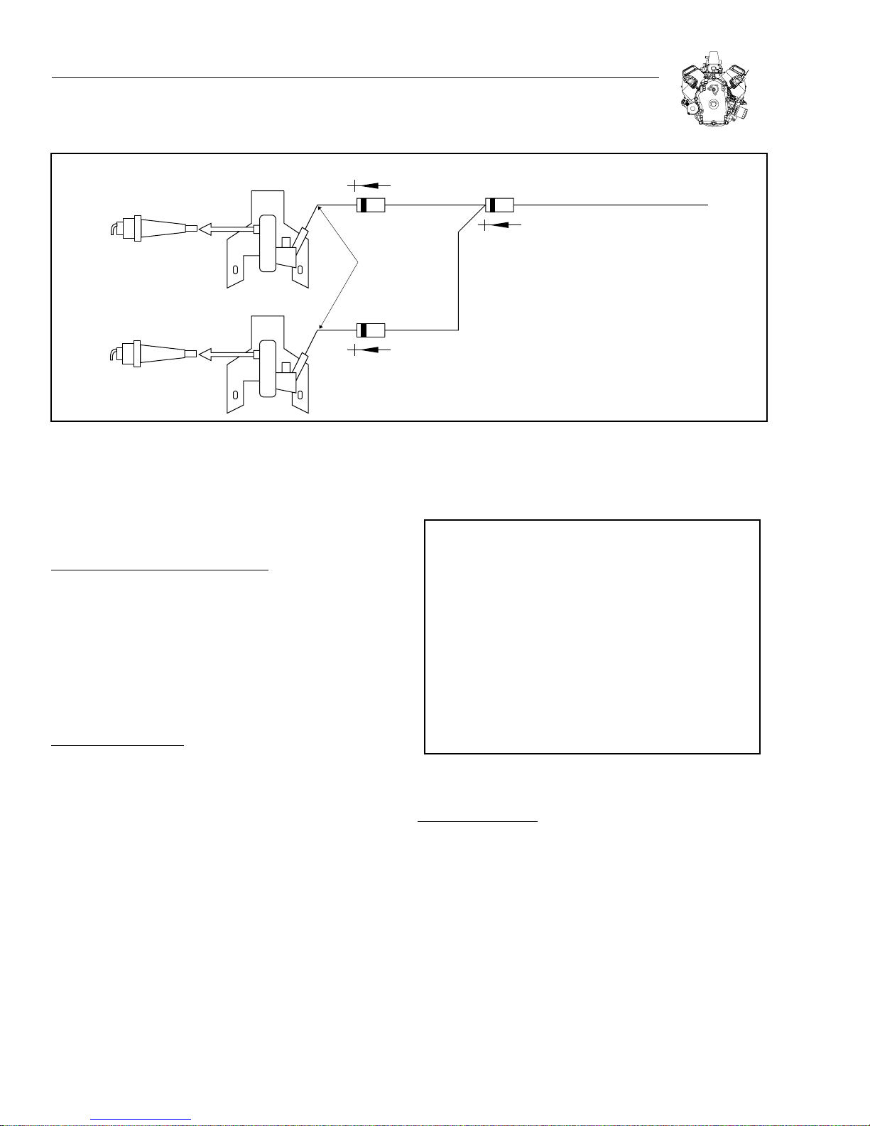
ENGINE WIRING HARNESS
The engine wiring harness consists of a ground wire with a diode for
each ignition coil and a separate wire for the carburetor solenoid. The
engine ground wires are connected to the wiring harness provided by
the equipment manufacturer.
NOTE: Models built after 2007 will have the diodes built into
the ignition coils or spark plug leads. Check the wire harness.
If there are no diodes in the harness, perform test on the coil
ground terminal.
See Figure 2-4.
TESTING GROUND WIRES:
Use a Digital Multimeter (Figure 2-1) to test the ground wires.
The following test will be made with the meter in the Diode Test position.
attached for remainder of test.
5. Touch BLACK test lead probe to terminal "B."
a. If meter "Beeps" once, diode is OK.
b. If meter makes a continuous tone, diode is defective (shorted).
Replace ground harness.
c. If meter displays "OL," diode is defective (open). Replace ground
harness.
6. Now repeat test for terminal "C." Results must be the same.
7. Replace wiring if defective.
8. If wiring tests good, proceed to IGNITION COILS section to replace
defective coil.
Note: See “Diode Failure Diagnosis”, Figure 2-3.
2
In the Diode Test position, the meter will display the forward voltage
drop across the diode(s). If the voltage drop is less than 0.7 volts,
the meter will "Beep" once as well as display the voltage drop. A
continuous tone indicates continuity (shorted diode) An incomplete
circuit (open diode) will be displayed as "OL."
Figure 2-1. Digital Multimeter
1. Insert RED test lead into
2. Inser t BLACK test lead into the “COM” receptacle in meter.
receptacle in meter.
Figure 2-2. Testing Ground Wire
SWITCH ON TURNED OFF CAUSE
Engine Runs
Shuts Off OK 1 Closed Diode
On 1 Cylinder
Engine Runs
(Both Cylinders)
Won't Run
Only One
Cylinder
1 Open Diode
2 Closed Diodes
(No Spark)
Engine Runs
(Both Cylinders)
Engine Won't Shut
Off
2 Open Diodes
Figure 2-3. Diode Failure Diagnosis
WIRE HARNESS CHECK
3. Rotate selector to (Diode Test) position.
4. Insert RED test lead clip into connector "A" (Figure 2-2). Leave
IGNITION COIL TESTING:
If ignition does not have spark, disconnect ground wire from ignition
2-1
Page 14
SECTION 2: IGNITION
DIODE (BUILT INTO COIL)
SPARK PLUG
GROUND
WIRE
HARNESS
DIODE (BUILT INTO COIL)
SPARK PLUG
Figure 2-4. Engine Wiring Harness
ground stud on engine and re-check. If ignition now has spark, check
wire harness for pinched wires, broken insulation or bad diode (if
equipped). If there is no spark, proceed to Removing Ignition Coil
section.
REMOVING AND INSTALLING WIRE HARNESS:
1. Remove spark plug leads.
IGNITION GROUND WIRE
DIODE BUILT IN HARNESS
ON OLDER MODELS
Note: The flywheel does not need to be removed to service ignition
except to check the flywheel key.
2. Remove intake manifold and cover intake ports with a shop
towel.
3. Remove rotating screen and blower housing.
4. Disconnect stop switch wire(s) at ignition coil(s).
5. Reverse order of above to install new wire harness.
REMOVING IGNITION COILS:
The condition of the ignition coils can be accurately diagnosed
using a spark tester (Generac P/N 0C5969) as described in
"TROUBLESHOOTING" Section 1.
1. Remove spark plug leads.
2. Remove intake manifold and cover intake ports with a shop
towel.
3. Remove rotating screen and blower housing.
4. Disconnect ground wire(s) at ignition coil(s).
5. Remove ignition coil screws and remove ignition coil(s). See
Figure 2-5.
Figure 2-5. Removing Ignition coil
INSTALL IGNITION COILS:
1. Turn flywheel so magnet is away from ignition coil.
2. Install ground wire onto tab terminal on ignition coil.
Note: Make sure wires are routed over ignition coil mounting posts
and away from flywheel.
3. Assemble ignition coil to engine, Figure 2-6.
a. Mounting holes in ignition coil are slotted. Push ignition coil
away from flywheel as far as possible and tighten screws.
4. Repeat for second ignition coil.
5. See Adjust Ignition Coil Air Gap.
2-2
Page 15

SECTION 2: IGNITION
FLYWHEEL
REMOVE FLYWHEEL:
1. Remove two screws that attach fan and fan retainer to
flywheel.
2. Remove fan retainer and fan.
GROUND WIRE ROUTING
Figure 2-6. Installing Ignition coil
ADJUST IGNITION COIL AIR GAP:
1. Rotate flywheel until magnet is aligned with ignition coil
laminations.
2. Place 0.20-.30 mm (.008"-.012") thickness, non-magnetic gauge
between magnet and ignition coil laminations, Figure 2-7.
3. Loosen mounting screws so magnet will pull ignition coil against
thickness gauge.
a. Torque screws to 4.75 Nm (40 in. lbs.).
0.20-0.30mm SHIM
SOCKET
WRENCH
3. Loosen flywheel nut until it is flush with end of crankshaft threads
(Figure 2-8.)
4. Install flywheel puller.
5. Tighten puller screws equally until flywheel loosens, Figure 2-9.
6. Remove puller, nut, washer and flywheel.
Figure 2-8. Removing Flywheel Nut
2
GROUND WIRE TERMINAL
Figure 2-7. Adjusting Air Gap
4. Rotate flywheel to remove thickness gauge.
5. Repeat for second ignition coil.
Note: Route ignition coil ground wire under breather tube and away
from the flywheel (see Figure 2-9).
Caution: Flywheel puller bolts may damage lighting coil if turned
*
in too far.
Caution: DO NOT strike flywheel with a hard object or a metal
*
tool as this may cause flywheel to shatter in operation. Always
use approved flywheel removal tools.
INSPECT FLYWHEEL KEY, KEYWAYS, FLYWHEEL AND
CRANKSHAFT:
Check flywheel key for damage. Check flywheel for cracks or keyway
damage. Also check crankshaft keyways and taper for damage, Figure
2-10. Replace crankshaft, if damaged.
2-3
Page 16

SECTION 2: IGNITION
COIL WIRE ROUTED
UNDER BREATHER
FLYWHEEL
NUT
Figure 2-9. Removing Flywheel
INSPECT HERE
Figure 2-10. Check Flywheel And Crankshaft
INSTALL FLYWHEEL:
Note: CLEAN flywheel and crankshaft taper removing all oil, dirt
or grease.
1. Insert flywheel key into crankshaft.
Figure 2-11. Torquing Flywheel Nut
Figure 2-12. Installing Flywheel Fan
3. Install washer and flywheel nut.
a. Torque flywheel nut to 204.0 Nm (150 ft. lbs.), Figure 2-11.
4. Assemble fan and retainer to flywheel, Figure 2-12.
a. Torque screws to 21.7 Nm (182 in. lbs.).
2. Align keyways and assemble flywheel to crankshaft.
2-4
Page 17

SECTION 3: CARBURETION AND FUEL SYSTEM
CARBURETOR TYPES
All Generac gasoline powered OHVI V-Twin engines utilize a
two-barrel type carburetor. Some LP engines use a single barrel
carburetor.
CARBURETOR REMOVAL - VERTICAL SHAFT
1. Unclip choke link from bellcrank and remove link from
carburetor.
2. Disconnect fuel-shutoff solenoid by unplugging the power wire.
3. Disconnect breather tube and EVAP hose if equipped.
4. Separate throttle link balljoint from carburetor by rotating the ball
socket.
5. Disconnect the fuel line clamp and the fuel line.
SPEED
CONTROL
LEVER
SLOW
BREATHER
HIGH
CHOKE
LINK
6. Remove the four nuts holding the carburetor and plenum to the
intake manifold (see Figure 3-6).
7. Remove the plenum, carburetor and gaskets from the manifold
and discard the gaskets.
CARBURETOR REMOVAL – HORIZONTAL SHAFT
1. Remove air cleaner cover and air cleaner.
2. Unthread yellow plastic knob from Summer/Winter intake control
(if equipped)
3. Remove dipstick tube hold down bolt and remove tube assembly
(see Figure 3-3).
4. Remove the four nuts and one bolt that retains the air cleaner base,
breather tube and EVAP hose if equipped; remove base (see Figure
3-3).
5. Remove fuel line clamp and fuel line from top of carburetor.
4 NUTS
BOLT
3
BELL CRANK
Figure 3-1. Vertical Shaft Carburetor
CLIP
DIPSTICK TUBE &
HOLD DOWN
Figure 3-3. Horizontal Shaft Carburetor
THROTTLE
LINK
Figure 3-2. Vertical Shaft Carburetor
Figure 3-4. Horizontal Shaft Carburetor
3-1
Page 18

SECTION 3: CARBURETION AND FUEL SYSTEM
CHOKE
LINK
Figure 3-5.
6. Remove choke link (Figure 3-5), throttle link (Figure 3-4) and fuel
shut-off solenoid wire from carburetor.
7. Slide carburetor off mounting studs.
CARBURETOR CLEANING
For cleaning purposes, the carburetor's float bowl may be removed.
It is recommended that all jetting be left in place while cleaning the
carburetor. Be sure to use a cleaner that won't damage rubber, neoprene, or plastic parts.
Note: The left and right main jets are different sizes.
If the fuel-shutoff solenoid is suspected of being faulty, it is replaceable
by simply unthreading it from the float bowl, and installing a new one
in its place. It can be checked by applying 12 volts to it. If you hear it
click, it is most likely working properly. If there is anything else wrong
with the carburetor, it is recommended that the entire carburetor be
replaced with a new one.
MANIFOLD
PLENUM
PLENUM
GASKET
CARBURETOR
GASKET
Figure 3-6.
8. Reinstall choke link on carburetor and clip the link into the
bellcrank.
9. Perform a static governor adjustment. (See “Static Governor
Adjustment”, page 4-2)
10. Start engine and allow to warm up for 5 minutes.
11. Move speed control lever to slow speed position and hold throttle
lever against idle stop screw.
12. Adjust the idle top screw to maintain ~1800 RPM idle.
13. Slowly move speed control lever to high speed position.
Note: Be careful not to lose the spring that is located inside
the fuel shutoff solenoid when removing the plunger.
CARBURETOR INSTALLATION - VERTICAL SHAFT
1. Slide new carburetor gasket and carburetor onto the studs.
2. Slide new plenum gasket and plenum onto the studs.
3. Install the four nuts and torque to 5.4 Nm (48 in. lbs.).
4. Connect the fuel line and clamp.
5. Reassemble the throttle link to the balljoint on the carburetor.
6. Connect the breather tube and EVAP hose if equipped.
7. Connect the fuel-shutoff solenoid.
Figure 3-7.
Note: The high speed screw may need adjusting to reach the speed
control stop without exceeding 3800 RPM.
14. With the speed control in the high speed position, adjust the high
speed screw to obtain the desired engine speed. Do not exceed
3800 RPM.
3-2
Page 19

CLINCHING
SCREW
SECTION 3: CARBURETION AND FUEL SYSTEM
10. Move speed control lever to slow speed position and hold throttle
lever against idle stop screw.
11. Adjust the idle stop screw to maintain ~ 1800 RPM idle.
12. Slowly move speed control lever to high-speed position.
IDLE
13. With the speed control in the high speed position, adjust the high
speed screw to obtain the desired engine speed. Do not exceed
3800 RPM.
FUEL PUMP
The fuel pump supplied with the engine is a pulse type pump. It uses
crankcase vacuum pulses drawn from the valve cover to pump the
fuel. It is capable of priming at 12" (30.5 cm) maximum lift, and has
a maximum outlet pressure of 1.5 psi. If the fuel pump is not working
properly, check the vent hole on the top of the pump for obstructions.
3
Figure 3.8.
CARBURETOR INSTALLATION – HORIZONTAL SHAFT
1. Install a new carburetor gasket and carburetor onto the studs.
2. Install air cleaner base, breather tube and EVAP hose (if
equipped), bolt and nuts and torque to 5.4 Nm (48 in. lbs.).
3. Re-attach choke and throttle links and solenoid wire to
carburetor.
4. Install fuel line and fuel line clamp.
5. Install oil fill tube and hold down bolt and torque to 4.7 Nm (40
in. lbs.).
6. Install air cleaner and air cleaner cover.
7. Install yellow knob for Summer/Winter control.
8. Perform a static governor adjustment. (See “Static Governor
Adjustment”, page 4-2)
9. Start engine and allow to warm up for 5 minutes.
If a fuel pump other than the factory recommended pump is used, the
fuel line pressure at the carburetor inlet must not exceed 3 psi. Pressures in excess of 3 psi may cause an over rich carburetor mixture
that would lead to engine damage.
TO
CARBURETOR
INLET
VENT HOLE
FUEL FROM
TANK
PULSE LINE
Figure 3-9. Fuel Pump
3-3
Page 20

SECTION 3: CARBURETION AND FUEL SYSTEM
SPRING
RETURN
1 2 3 4 5 6
LOWER
DIAPHRAGM
UPPER
DIAPHRAGM
VENT: UPPER
VENT ASSEMBLY
FUEL
CHECK-
VALVE 1
FUEL
CHECK-
VALVE 2
HARDWARE
Figure 3-10. Fuel Pump Assembly
Fuel Pump Breakdown (see Figure 3-10):
1. Lower Spring Assembly
2. Lower Diaphragm
3. Check Valve Assembly
4. Upper Diagram
5. Upper Vent Assembly
6. Mounting Hardware x 2
As crankcase vacuum is built up the Lower Diaphragm pulls down
against the Spring Return and allows fuel to flow through Check-Valve
2. As pressure builds up in the crankcase, the Spring Return pushes
up against the Lower diaphragm, allowing fuel will flow through CheckValve 1 and out the fuel port.
LP (LIQUID) - FUEL SYSTEM
Proper service and repair is important to the safe and reli-
*
able operation of all gaseous fueled engines. Any servicing
or testing of a gaseous fueled engine must only be performed
by qualified personnel. Always follow applicable installation
and service procedures. An example of these requirements
is found in NFPA-58 for liquid propane. These are US Federal
standards. Worldwide standards vary. Local, city, and state
requirements may also have certain requirements that must
be observed.
LP (Liquefied Petroleum Gas) is a gaseous fuel and when stored under
pressure, becomes a liquid. Although a vapor forms at the top of the
tank, this particular system uses a liquid withdrawal method, drawing
liquid from the bottom of the tank.
This is accomplished with a special valve that is installed on a normal
propane cylinder with a tube that is attached to the valve and extends
to the bottom of the storage tank. Pressure in the tank forces liquid
propane through the tube when the valve is opened.
The Generac LP system starts with a pressure relief valve to prevent
excessive pressure from building in the system during shutdown.
This is followed by a 12 volt (normally closed) electric solenoid,
which prevents the flow of fuel when the ignition key is off. When the
ignition key is turned on, the solenoid opens and allows liquid LP to
flow to the regulator.
The liquid fuel vaporizer/regulator converts liquid propane to vapor.
The vaporizer/regulator uses either spent engine cooling or engine oil to
provide heat to aid in the evaporation process. The vaporizer/regulator
controls the vapor supply to an amount required by the engine. The
engine’s intake vacuum draws LP into the fuel mixer on an on-demand
need. When the engine is off, LP no longer flows from the vaporizer/
regulator to the engine (see Figure 3-32).
TROUBLE SHOOTING
CAUTION! Gaseous fuels are highly explosive; do not use flame
*
or heat to test the fuel system for leaks. LP gas is heavier than
air and tends to settle in low areas; even the slightest spark
can ignite these gases and cause an explosion.
Note: Don’t assume that the fuel system is the problem. Verify that
the engine has spark and enough compression to start the engine
before proceeding with the following steps.
3-4
Page 21

SECTION 3: CARBURETION AND FUEL SYSTEM
TESTING THE FUEL SHUT-OFF SOLENOID
1. Remove the spark plug wires from each spark plug to prevent
accidental starting of the engine.
2. Check for 12 volts DC at the solenoid terminal.
See Figure 3-11.
a. Place one hand on the fuel solenoid and turn the ignition switch to
the run position. You should be able to feel the solenoid actuate
as well as hear an audible click. Replace the solenoid if it does
not actuate. Some systems will delay power to the solenoid until
full oil pressure is reached during cranking.
3. If the solenoid is opening properly, proceed
to “TESTING AND REPAIRING THE LPG
VAPORIZER/REGULATOR.”
4. Reconnect the spark plug leads when finished
COIL BOLT
COIL SPOOL
RESEVOIR BOLT
Figure 3-12. LPG Solenoid Valve Torque and
Lubrication Points
SEALING GASKET
SEALING GASKET
SEALING GASKET
SEALING GASKET
3
12 VOLT WIRE
Figure 3-11. LPG Solenoid Valve
DISASSEMBLY AND ASSEMBLY OF
LPG SOLENOID VALVE
If the solenoid valve is removed for cleaning or replacing the filter, it is
recommended that the special synthetic sealing gaskets be replaced.
When installing new sealing gaskets, they should be lubricated using
an O-ring lubricant. DO NOT RE-USE O-RINGS!
For improving the functional features and lifetime of the solenoid, it
is recommend that the gaskets and filter be replaced after 500 hours
of operation.
NOTE: For correct solenoid valve fitting, it is essential that the
following torque values be observed:
1 Coil Bolt 7.85 Nm (70 in. lbs.)
2 Reservoir Bolt 11.8 Nm (104 in. lbs.)
3 Coil Spool: 16.6 Nm (147 in. lbs.)
TESTING AND REPAIRING LPG
VAPORIZER/REGULATOR
SPECIAL EQUIPMENT REQUIRED:
1. Air pressure at 100 psi, and air pressure gauge 0-15 psi, with
connecting hose and fittings to attach to the 1/8” NPT female pipe
connection.
2. Liquid leak detector to check for leaks (recommended).
REPAIR KIT CONTENTS:
(Refer to Parts Manual for specific part numbers.)
Pin, Pivot, Secondary Reg Lever
Lever, Assembly Reg Secondary
Diaphragm, secondary
Assembly. Diaphragm, primary
Assembly, Lever, Primary
Pin, Pivot, Primary
3-5
Page 22

SECTION 3: CARBURETION AND FUEL SYSTEM
NOTE: test regulator on engine first or, for scheduled maintenance,
proceed to "remove regulator and dismantle as follows".
1. Make sure the fuel tank(s) have an adequate supply of fuel.
2. Make sure the valve on the tank is fully open (turned counterclockwise).
Note: This fuel system is under high pressure.
3. While the fuel is off, install the primary pressure test gauge at the
1/8” primary test port opening at the side of the regulator, marked
“PRI”. See Figure 3-14.
4. Disconnect the vapor hose at the Carburetor or Carburetor
Adapter.
5. Turn on the ignition to open the fuel solenoid valve.
6. If the engine is equipped with an engine controlled safety switch,
bump the starter to make contact and open the fuel solenoid valve.
7. Primary pressure should be 0.5 to 4.5 psi and hold
pressure.
8. If primary pressure is too high or too low and leakage is observed
at the vapor hose, the regulator must be re-moved, disassembled,
cleaned and new parts installed.
REMOVE REGULATOR AND DISASSEMBLE AS FOLLOWS:
Caution! Prior to the removal of any LP system components,
*
disconnect the battery and turn off the fuel supply at the tank(s).
1. Remove the five secondary cover screws, 10-32 x 0.630”, and lift
the cover off the regulator body and secondary diaphragm (see
Figure 3-13). The cover has a tendency to stick to the diaphragm
and gasket. A slight tap on the edge of the cover with a screwdriver
handle or a soft face hammer will loosen the cover.
Note: Do not pry in between the cover and the body. Damage to the
sealing surface may result.
2. After the cover has been removed, lift up an edge of the diaphragm.
Observe how it is attached to the secondary lever. See Figure 3-14.
Figure 3-13. Remove Five Secondary Cover Screws
4. Remove the four screws, 10-32 x 0.630”, holding the primary
diaphragm cover in place. If the cover sticks, use a screwdriver
handle or soft-faced hammer to dislodge it. Observe that the
longer (2),10-32 x 1.0”, of the six screws are at the top of the
cover. Remove primary spring. See Figure 3-16.
3. Remove the two screws, 10-32 x 0.310”, holding the secondary lever pivot pin and remove the secondary lever and spring.
The secondary pivot pin is 1.20” long. See Figure 3-15.
PRESSURE TEST POINT
Figure 3-14. Lift Edge of Diaphragm
5. Remove the primary diaphragm. See Figure 3-17.
6. Remove the two screws, 8-32 x 0.375” long. See Figure
3-18.
Note: Remove oil and foreign deposits from all chambers and
parts. DO NOT APPLY LIQUID CLEANERS TO THE DIAPHRAGMS
AND NEOPRENE FACED VALVES.
3-6
Page 23

Figure 3-15. Remove Secondary Lever and Spring
SECTION 3: CARBURETION AND FUEL SYSTEM
3
Figure 3-18. Remove/Replace Two Screws 8-32 x 0.375” long
REASSEMBLY OF REGULATOR:
Figure 3-16. Remove Primary Diaphragm Cover
and Primary Spring
1. Carefully clean and inspect all metal parts-springs, levers, pivot
pins and screws. Replace all parts that are included in the repair
and rebuilding kits.
2. Carefully clean the body casting and inspect all sealing surfaces.
Wipe with a clean rag. Inspect the primary section for foreign
materials that might loosen and damage the soft face valves.
3. Blow out the fuel inlet passage and outlet passages. Be sure no
foreign material remains in these passages.
4. Inspect the primary orifice and the secondary orifice for nicks
scratches or uneven wear.
IMPORTANT! If the primary or secondary seats show any of the
above mentioned conditions, the regulator is not rebuildable and
must be replaced.
5. Lay the regulator flat on a clean working surface with the primary
section up.
6. Replace the primary pivot pin, 0.890”, bridge and two screws,
8-32 x 0.375”. Tighten screws evenly to 30 in. lbs. ±3 in. lbs.
(3.39 Nm ± 0.339 Nm). Rock the primary lever assembly to
ensure that it pivots freely. See Figure 3-18.
7. Engage the primary diaphragm pin with the slot in the primary
lever. Rotate the diaphragm to align the cover screw holes as
shown in Figure 3-19.
Figure 3-17. Remove Primary Diaphragm
8. Place primary spring, small side up, on top of diaphragm. Install
primary cover and screws. Remember, the 2 longer, 10-32 x 1.0”,
screws go to the top of the primary cover. Tighten evenly, in a
criss-cross pattern, to 30 in. lbs. ±3 in. lbs. (3.39 Nm ±0.339
Nm). See Figure 3-20.
3-7
Page 24

SECTION 3: CARBURETION AND FUEL SYSTEM
3-23.
Figure 3-19. Rotate The Diaphragm To Align the
Cover Screw Holes
Figure 3-20. Install Primary Spring, Primary Cover and Screws
9. Place secondary valve spring (5/16” dia. x 5/8’ long) in spring
recess near secondary orifice. Replace secondary lever, pivot
pin, 1.19” long, and two screws, 10-32 x 0.310”. Make sure the
spring fits over the spring boss on the secondary lever. Tighten
screws evenly to 30 in. lbs. ±3 in. lbs. (3.39 Nm ± 0.339 Nm).
See Figure 3-21.
10. The secondary lever (except for the bent tail tip) should be level
or flush with the top of casting. Bend tail end of lever if necessary
but do not use excessive force on the rubber valve against the
orifice. See Figure 3-22.
11. The secondary lever has a soft valve surface on an aluminum
insert which must be swiveled into flat contact with the orifice.
Place a pointed instrument in the top indentation of the valve. Apply
slight downward pressure and with a gentle rotary motion, swivel
the valve into flat contact with the orifice. These valve inserts are
not sold separately but are crimped at the factory with proper
tension to allow movement but still hold their position. See Figure
Figure 3-21. Install Secondary Valve Spring,
Lever and Pivot Pin
Figure 3-22. Make Sure Secondary Lever is Flush
With Top of Casting
12. Attach primary pressure gauge at the primary pressure test por t
opening. See Figure 3-24.
13. Attach air pressure hose to the regulator fuel inlet with
approximately 100 psi, ±10 psi air pressure. See Figure
3-25.
14. Slowly depress the secondary lever bent tail end until you are
able to detect flow out of the secondary orifice. Let the lever then
slowly return to the closed position. Observe the primary pressure
reading on the installed gauge. It should be between 0.8 and 2.5
psi. If it is not, recheck your work in the primary fuel section. See
Figure 3-26.
3-8
Page 25

SECTION 3: CARBURETION AND FUEL SYSTEM
3
Figure 3-23. Positioning Secondary Lever Valve
Figure 3-24. Primary Pressure Test Port Opening
Figure 3-26. Check Primary Pressure Reading
15. Check around the secondary seat for leaks using a liquid
leak detector solution. If a leak is detected, repeat Step 11
to insure no leakage at the secondary seat. See Figure 3-27.
Figure 3-27. Check Secondary Seat for Leaks
16. Turn off the air supply. Install the secondary diaphragm by
hooking the secondary lever through the center pin. If the screw
hole tabs do not line up with the casting, remove and rotate
the diaphragm 180 degrees and reinstall. See Figure 3-28.
Figure 3-25. Attach Air Pressure Hose
17. Install secondary cover and align the cover and diaphragm
notches. Carefully start all five screws, 20-32 x 0.630”, through
cover and diaphragm holes. Tighten evenly, in a criss-cross pattern, to 30 in. lbs. ±3 in. lbs. (3.39 Nm ± 0.339 Nm). See Figure
3-29.
3-9
Page 26

SECTION 3: CARBURETION AND FUEL SYSTEM
Figure 3-28. Install Secondary Diaphragm
b. Connect LP line(s), reconnect battery and turn on fuel supply at
the tank(s).
c. Turn ignition switch to the "ON" position to verify that the solenoid
is opening.
d. Check all fuel connections with a leak detector. If leaks are pres-
ent, go back to Step 20a.
e. Run the engine until it is at full operating temperature.
21. Repair is now complete.
Figure 3-29. Install Secondary Cover
18. Draw a bubble of leak detector over the “OUTLET” port. The
bubble should hold for several seconds with the regulator inlet
pressurized. Return to step 10 if the bubble doesn’t hold for several
seconds. See Figure 3-30.
19. Remove air pressure supply and primary pressure test gauge.
Replace the 1/8” pipe plug in the primary pressure test opening.
See Figure 3-31.
20. Install the regulator.
a. Clean all threaded areas and use a commercially available pipe
sealant. Make sure sealant does not get inside of the regulator.
Figure 3-30. Check Outlet Port
Figure 3-31. Re-install Pipe Plug in Test Opening
3-10
Page 27

MECHANICAL GOVERNOR
DISASSEMBLE:
1. Drain the oil from the engine.
2. Remove any rust, nicks, or burrs from the crankshaft.
3. Remove the four (4) oil cooler screws.
4. Disconnect the wiring from the oil pressure switch.
5. Remove the governor lever from the shaft.
6. Separate the ball joint on the swinging arm.
SECTION 4: GOVERNOR CONTROLS AND GOVERNOR
GOVERNOR
SPOOL
OIL
PASSAGE
O-RING
7. Remove all of the crankcase bolts and slide the crankcase
cover off.
8. Discard the crankcase gasket & oil passage o-ring.
GOVERNOR
Both the spool and the flyweights must move freely for the governor
to work properly. Check for wear on the spool and flyweights. If
wear is noticed, change the governor gear assembly (gear and flyweights), spool, and governor arm. Lubricate all moving parts when
reassembling.
GOVERNOR REMOVAL AND INSTALLATION:
1. Leverage gear assembly and governor spool off of governor
shaft.
GOVERNOR ASSEMBLY
SPOOL MUST ENGAGE UNDER BOTH FLYWEIGHTS
4
GOVERNOR GEAR ASSEMBLY
Figure 4-1. Governor Gear Assembly and Spool
2. Remove any remaining plastic from the notch in the governor
shaft.
3. Check that all the governor bearing parts (top plate, bearing,
and bottom plate) are on the shaft, and that it moves smoothly.
(See Figure 4-2)
4. Slide the new gear assembly and spool onto the governor shaft.
Slide until the gear hooks into the notch in the governor shaft.
(See Figure 4-2)
SPOOL
GOVERNOR GEAR AND
FLYWEIGHT ASSEMBLY
PRESS THIS END INTO BLOCK
37 mm
GOVERNOR SHAFT
(37 mm / 1.456” EXPOSED SHAFT)
Figure 4-2. Governor Assembly and Components
4-1
ROLLER BEARING
CUPPED SIDE OF BEARING FACES DOWN
AWAY FROM GEAR
ROLLER BEARING PLATES
Page 28

SECTION 4: GOVERNOR CONTROLS AND GOVERNOR
C
3
0
9
8
0
6
GOVERNOR ARM
If the governor arm does not move freely, or if the arm feels loose in the
bushings, it may need replacing. If wear is noticed, change the governor arm, governor gear assembly (gear and flyweights), spool, and
bushings as needed. Lubricate all moving parts when reassembling.
Figure 4-3. Governor Arm Assembly
DISASSEMBLE GOVERNOR ARM:
1. Remove the e-clips.
2. Slide the arm down and out of the bushings.
3. Replace any parts that appear worn.
Note: The lower bushing is a slip fit, and the upper bushing is
pressed in.
ASSEMBLE GOVERNOR ARM:
1. Slide the thrust washer part way onto the new governor
arm.
2. Insert the governor arm in the lower bushing holder, and slide it
part way in.
3. Install lower e-clip on the arm, and slide the thrust washer down
to it.
4. Slip the lower bushing part way on to the arm.
5. Slide the arm in until the thrust washer is tight.
6. Slide the lower bushing down and into it’s holder, then install the
upper e-clip.
ASSEMBLE CRANKCASE COVER:
1. Clean any old gasket material from the crankcase and cover
mating surfaces.
2. Be sure that the new oil passage o-ring is in place (see
Figure 4-1).
TORQUE SEQUENCE FOR
RANKCASE COVER:
-4-5-6-7-8-9-1
1-2-
1
Figure 4-4. Crankcase Bolt Torque Sequence
4-2
Page 29

3. Put a new gasket on the crankcase.
SECTION 4: GOVERNOR CONTROLS AND GOVERNOR
Note: On vertical shaft engines, align the camshaft drive and oil
pump gerotor.
4. Slide the crankcase cover back on the crankcase.
Note: Hold the governor arm in the counter-clockwise position
while installing.
5. Start all of the crankcase bolts, and then torque them to 47.5 Nm
(35 ft. lbs.), following the proper torque sequence (see Figure
4-4).
6. Reconnect the ball joint on the swing arm.
7. Place the governor lever on the governor arm. Place the governor
spring in the 4th hole out.
8. Perform a static governor adjustment (see below).
9. Reconnect the wires to the oil pressure switch.
10. Reattach the oil cooler to the blower housing.
STATIC GOVERNOR ADJUSTMENT
Determine which version of governor linkage is installed on the engine.
Refer to Figures 4-5 (earlier version) and 4-6 (later version).
1. Loosen the clinching screw on the governor lever.
2. Rotate the governor arm clockwise and hold governor lever in
WOT (Wide Open Throttle) position.
GOVERNOR LEVER
GOVERNOR
ARM
CLINCHING BOLT
4
Figure 4-6. Static Governor Adjustment (Later Version)
3. While holding this position, torque the clinching screw to 11.3
Nm (100 in. lbs.).
4. Check to make sure that the throttle travels from WOT to IDLE. If
it doesn't, the governor needs to be reset again.
IDLE
CLINCHING
SCREW
Figure 4-5. Static Governor Adjustment
Figure 4-7. Dynamic Governor Adjustment (Earlier Version)
DYNAMIC GOVERNOR ADJUSTMENT
1. Start engine and allow to warm up for 5 minutes.
2. Move speed control lever to slow speed position and hold throttle
lever against idle stop screw (see Figure 4-7).
3. Adjust stop screw to maintain 1800 RPM idle.
4. Slowly move speed control lever to high-speed position. Do
not exceed 3800 RPM (see Figures 4-7 or 4-10 depending on
governor version).
Note: On the later governor version, insert an allen wrench or
similar object into the hole in the control panel behind the speed
control lever. This acts as a temporary stop during adjustment.
Note: The high-speed screw may need adjusting to reach the speed
control stop without exceeding 3800 RPM.
5. With the speed control in the high-speed position, adjust the highspeed screw to obtain the desired engine speed (see Figures 4-7
or 4-10 depending on governor version).
4-3
Page 30

SECTION 4: GOVERNOR CONTROLS AND GOVERNOR
HIGH
SPEED
SCREW
Figure 4-8. Dynamic Governor Adjustment
(Vertical Shaft)
SPEED
CONTROL
LEVER
ALLEN
WRENCH
Figure 4-9. Dynamic Governor Adjustment
(Horizontal Shaft)
Figure 4-10. Dynamic Governor Adjustment
(Horizontal Shaft)
4-4
Page 31

SECTION 5: CYLINDER HEAD AND VALVES
R
R
R
OUSING
COOLER
SS
Y
N
D
GENERAL INFORMATION
Compression testing information and procedures is described in Section 1, under “Troubleshooting”.
Cylinders are numbered as shown in Figure 5-1.
Note: Cylinder #1 is closest to the flywheel.
Figure 5-1.
REMOVE CYLINDER HEADS
Remove exhaust system from engine. Disconnect choke and throttle
control cables. Remove spark plugs.
1. Remove the parts depicted in Figure 5-2.
a. Discard gaskets and valve cover seals.
REMOVE ROCKER ARMS:
1. Unlock jam nuts and remove two ball studs and rocker arm
assemblies (see Figure 5-3).
2. Remove push rods and identify each.
Note: Push rods develop a wear pattern. Mixing them from side to
side can increase this wear, leading to more frequent adjustments
and or loss of performance.
5
FINGER GUAR
ROTATING SCREE
INTAKE MANIFOLD
EMBL
A
IL
BLOWER H
PPER WRAPPE
LOWER WRAPPE
VALVE COVE
Figure 5-2.
5-1
Page 32

SECTION 5: CYLINDER HEAD AND VALVES
BALL STUD
ROCKER ARM
JAM NUT
PUSH ROD GUIDE
(TABS MUST FACE UPWARD)
Figure 5-4. Remove Cylinder Head
Figure 5-3.
3. Remove push rod guide plate.
4. Remove head bolts and cylinder head (Figure 5-4).
a. Discard gasket.
5. Repeat Steps 1-4 for other cylinder head.
DISASSEMBLE CYLINDER HEAD
1. Place a shop rag or short section of rubber fuel line under
valves inside combustion chamber to hold valve in place while
compressing spring.
2. Hold down valve spring retainer with a valve spring compressor
(Figure 5-5). Remove the following:
a. Valve spring keepers
b. Valve spring retainer
c. Valve spring
d. Intake and exhaust valves
3. Remove and discard valve stem seals (Figure 5-6).
Figure 5-5. Removing Retainers
VALVE STEM SEAL
(USED ONLY ON INTAKE SIDE)
Figure 5-6. Removing Valve Stem Seals
5-2
Page 33

SECTION 5: CYLINDER HEAD AND VALVES
1/32”
MINIMUM
1.2 MM TO 1.6 MM
(3/64” - 1/16”)
SEATING AREA CENTERED
ON VALVE FACE
45° VALVE FACE ANGLE
INSPECT AND REPAIR
1. Check cylinder head (Figure 5-7). Be sure all gasket material is
removed from surfaces before checking.
a. Inspect cylinder head for cracks or damage.
b. Use a surface plate or straightedge and check cylinder head
mounting surface for distor tion.
If mounting surfaces are distor ted more than 0.1 mm (.004"), the
cylinder head must be replaced.
Note: It is not recommended that cylinder head mounting surfaces
be resurfaced.
REFACE VALVES AND SEATS:
1. Valve seats may be reconditioned using a valve seat cutter.
If valve seat is wider than dimension shown in Figure 5-9, a
narrowing cutter should be used to ensure that contact area
of valve seat is centered on face of valve (see Figure 5-10).
a. Use a 60° cutter to narrow seat from bottom and a 15° cutter to
narrow seat from top (Figure 5-9).
Note: If valve seat is loose or cracked, replace cylinder head.
0.8 MM TO 1.2 MM
(1/16” - 3/64”)
44°
60° CUTTER
15° CUTTER
5
2. Clean the valve guides and measure their I.D. using a split ball
bore gauge (Figure 5-8).
a. Replace head if either valve guide measures 7.06 mm (0.278 in.)
or more. Valve guides should not be replaced.
SPLIT BALL
BORE GAUGE
Figure 5-7. Check Cylinder Head Distortion
Figure 5-8. Check valve guides
Figure 5-9. Valve Seat Dimensions
2. Valve faces may be resurfaced to 45°. See Figure 5-10 for dimensions for valves.
Note: In most instances it is more economical to replace the valves
than to reface them.
Figure 5-10. Valve Dimensions
3. Measure valve stem diameter at specified distance from end of
valve, as shown in Figure 5-11.
Replace if less than 6.9 mm (0.272 inches), or if total clearance
between valve stem and valve guide exceeds 0.12 mm (0.0047
in).
5-3
Page 34

SECTION 5: CYLINDER HEAD AND VALVES
1.600” [40 mm]
Figure 5-13. Install Valve Stem Seals
Figure 5-11. Measure Valve Stem Diameter
4. Check valve springs for free length (Figure 5-12).
Replace if free length is less than 36.5 mm (1.437 inches).
Figure 5-12. Check Valve Springs
ASSEMBLE CYLINDER HEAD
1. Install new valve stem seals.
a. Press seal on to intake valve guide bushing until it bottoms (Figure
5-13).
b. Lubricate inner top lip of valve stem seal with oil.
2. Install valves (Figure 5-14).
Note: Lightly coat valve stems with oil before installing valves. Be
sure lubricant is not on valve face and seat.
INTAKE VALVE
EXHAUST VALVE
Figure 5-14. Install Valves
3. Place a shop rag or short section of rubber fuel line under valves
inside combustion chamber to hold valve in place while compressing spring.
4. Install valve springs and valve spring retainers over valve
stems.
5. Compress valve spring and install keepers (Figure 5-15).
5-4
Page 35

Figure 5-15. Compress valve spring and install keepers
F
TORQUE SEQUENCE FOR HEADS:
6. Repeat procedure for other valve(s).
SECTION 5: CYLINDER HEAD AND VALVES
ADJUST VALVE CLEARANCE
1. Set No. 1 cylinder at TDC, compression stroke.
a. Adjust rocker arms and check clearance (Figure 5-17).
Valve Clearance (cold) Intake and Exhaust 0.076 mm (.003“).
b. Torque jam nut to 19 Nm (168 in. lbs.).
5
7. Set push rod guide plate in place with tabs facing upward, and
loosely install rocker arm assemblies (ball stud, rocker arm and
jam nut).
8. Repeat Step 7 for other head.
INSTALL CYLINDER HEAD
1. Install cylinder head with new gasket.
2. Torque head bolts in sequence shown to 29.9 Nm (22 ft.
lbs.) (Figure 5-16).
3. Insert push rods into recess in tappets.
Figure 5-17. Adjust Valve Clearances
2. Set No. 2 cylinder at TDC, compression stroke and repeat Steps
1a and 1b above.
3. Install valve covers with new gaskets.
a. Torque screws to 6.8 Nm (60 in. lbs.).
REASSEMBLE
Install all parts shown in Figure 5-18.
1. Install cylinder wrappers.
a. Torque M5 screws to 2.8 Nm (25 in. lbs).
b. Torque M6 screws to 4.5 Nm (40 in. lbs).
2. Install spark plugs.
a. Torque to 19 Nm (168 in. lbs.).
3. Install exhaust manifold.
a. Torque screws to 19 Nm (168 in. lbs.).
4. Install blower housing.
A-B-C-D-E-
Figure 5-16.
a. Torque screws to 4.5 Nm (40 in. lbs).
5. Install intake manifold with new gaskets.
a. Torque screws to 19 Nm (168 in. lbs.).
b. Assemble governor link to carburetor.
5-5
Page 36

SECTION 5: CYLINDER HEAD AND VALVES
R
R
R
OUSING
COOLER
SS
Y
N
D
6. Install rotating screen.
a. Torque screws to 1.9 Nm (17 in. lbs).
7. Install finger guard.
a. If engine is equipped with hex head screws, torque screws to
4.5 Nm (40 in. lbs).
b. If engine is equipped with finger screws, tighten screws by hand
to approximately 1.3 Nm (12 in. lbs.).
FINGER GUAR
8. Assemble air cleaner.
9. Make Static and Dynamic Governor adjustments as outlined on
Page 4-3.
ROTATING SCREE
INTAKE MANIFOLD
EMBL
A
IL
BLOWER H
PPER WRAPPE
LOWER WRAPPE
VALVE COVE
Figure 5-18. General Assembly
5-6
Page 37

SECTION 6: ELECTRIC STARTER
GENERAL INFORMATION
The starter motor utilizes a solenoid, similar to an automobile star ter, to
assist in pinion gear engagement. When the starter motor is activated,
the pinion gear engages a ring gear attached to the engine flywheel
and cranks the engine.
Figure 6-1. Starter Motor
TROUBLESHOOTING
NOTE: If a starting problem is encountered, the engine itself should
be thoroughly checked to eliminate it as the cause of starting
difficulty. It is a good practice to check the engine for freedom
of rotation by removing the spark plugs and flywheel guard and
turning the crankshaft with a socket and ratchet or breaker bar,
to be sure it rotates freely.
WARNING: Do not rotate engine with electric starter while spark
*
plugs are removed unless using a compression gauge. Arcing
at the spark plug ends may ignite the gasoline vapor exiting
the spark plug hole.
ENGINE WILL NOT CRANK:
a. Faulty safety interlocks.
b. Discharged or defective battery.
c. Faulty electrical connections.
d. Faulty starter motor switch (open circuit).
e. Open circuit in star ter motor.
f. Brushes sticking, etc.
g. Faulty solenoid.
STARTER MOTOR SPINS BUT DOES NOT CRANK ENGINE:
a. Sticking pinion gear due to dir t.
b. Damaged pinion or ring gear.
c. Battery faulty or damaged.
d. Incorrect rotation due to
counterclockwise viewed from pinion gear.
e. Damaged solenoid
STARTER MOTOR SPINS BUT WILL NOT STOP:
a. Defective star ter switch.
b. Solenoid stuck engaged.
reversed motor
polarity – all motors rotate
TEST EQUIPMENT
DIGITAL MULTIMETER:
A digital multimeter (VOM) may be used to read volts, ohms, amperes
and test diodes (rectifiers), Figure 6-2.
NOTE: The Digital Multimeter is equipped with two fuses to prevent
damage to the meter in the event that the input limits are exceeded.
If the meter displays a reading of 0.00 when testing DC output, check
fuses in meter. Refer to VOM operators manual for procedure for
checking fuses.
6
ENGINE CRANKS SLOWLY:
a. Additional load affecting performance (see note above).
b. Discharged battery.
c. Faulty electrical connection (battery circuit).
d. Discharged battery (see alternators).
e. Dirty or worn star ter motor commutator, bearing, weak magnets,
etc.
f. Worn brushes or weak brush spring.
g. Wrong oil viscosity for temperature expected.
h. Battery leads too long or wire too small.
i. Battery too small.
Figure 6-2. Digital Multimeter
6-1
Page 38

SECTION 6: ELECTRIC STARTER
TEST STARTER MOTOR
TESTING STARTER SOLENOID:
The solenoid is a normally open, electrically activated switch. With
the keyswitch in the “START” position, the switch closes, allowing
battery current to flow to the star ter motor and crank the engine.
1. The solenoid may be tested while mounted on the engine.
2. A jumper test lead is required for this test.
3. Remove positive battery cable from battery. Then remove battery
cable from stud terminal on solenoid.
4. Disconnect wire from tab terminal on solenoid.
5. Keyswitch must be in “OFF” position.
6. Insert red test lead into receptacle in meter.
7. Insert black test lead into
8. Rotate meter selector to position.
9. Attach one meter test lead to each stud terminal on the solenoid
(Figure 6-3).
10. Attach one end of jumper lead to positive terminal on battery.
11. Touch jumper wire to tab terminal on solenoid.
receptacle in meter.
is being used. Check the engine manufacturer's Operator's Manual for
battery size recommendations.
With the engine and all other accessories turned off, measure the
battery voltage across the battery posts using a VOM set to the 20
Volt scale. Do not measure across the the battery wire terminal ends.
Voltage should read 12.5 volts or higher.
Do not crank the engine longer than 15 seconds during any of the
following tests. To check starter voltage drop:
1. Prevent the engine from starting by either grounding the ignition
at the ground stud on the side of the engine or removing the spark
plug leads. Using a VOM, place the (+) positive lead on the positive post of the battery. The (-) negative lead on the negative post
on the battery. Crank the engine and observe the reading on the
VOM.
2. Next, place the (+) positive lead of the VOM on the starter’s battery terminal stud and the (-) negative lead on the starter housing.
Crank the engine and observe the VOM reading.
3. Compare the two voltage readings. If the two readings are the
same (or a difference of one volt or less) then there is no excessive
voltage drop on the positive side. If a voltage drop of greater than
one volt is seen, proceed to Step 4.
a. An audible “Click” should be heard as the solenoid switch
“closes.”
b. Meter should make a continuous tone (continuity).
Figure 6-3. Testing Solenoid
CHECKING STARTER VOLTAGE DROP
Before starting this test, make sure the battery is at least 70 percent
charged (12.5 volts or higher). Also make sure the correct sized battery
Figure 6-4. Testing Starter Voltage Drop
4. Set the VOM on the 2 volt scale. Place the (+) positive lead on
the (+) positive battery post and the (-) negative lead on the (+)
positive terminal stud on the starter. Refer to figure 6-4. With
the engine still disabled, crank the engine and observe the VOM
reading. There should be less than a 0.2 volt drop. If greater, a
check of each wire and terminal connection should be made. At
each connection, no more than 0.2 volts should be seen.
6-2
Page 39

SECTION 6: ELECTRIC STARTER
5. Check the (-) negative side of the system. Place the VOM (+)
positive lead on the starter case and the other lead on the (-)
negative post of the battery. Crank the engine and observe the
reading, it should be less than .2 volts.
6. If greater than 0.2 volts, check all wire connections on the (-)
negative side of the starter. There should not be any readings
higher than 0.2 volts.
STARTER AMP DRAW TEST
This test requires a special tool called a clamp-on type amp meter.
Most repair shops should be able to perform this test.
1. Place the amp meter clamp on the (+) positive cable running
from the battery (+) post to the starter post.
2. Ground the ignition and crank the engine (no longer than 15
seconds). The starter amp draw should be less than 100 amps
during cranking.
Excessive draw could be caused by the following:
•Faulty starter. To verify this, the starter should be removed from
the engine and bench checked prior to replacing. Do an amp draw
test on the bench. The starter should not exceed 62 amps with a
minimum pinion speed of 3250 rpm. See Figure 6-5.
•Engine oil viscosity too heavy (see engine manufacturer’s Opera-
tors Manual).
•Some equipment manufacturers may use a constant drive pump,
which may have too heavy of oil or too tight of belt tension.
•Internal engine problem. Turn the engine over with a socket and
ratchet to make sure it turns over easily.
•Battery cable is loose or too small.
•Battery terminals are corroded.
•Battery CCA too low.
BATTERY INFORMATION
A 12 volt battery is required to operate the starter motor on Generac
OHVI V-Twin engines. For best starter life and performance, the battery should have a rating of at least 450 cold cranking amps at 0°F for
gasoline engines and 525 cold cranking amps for LP engines.
WARNING: Wear eye protection when servicing the battery.
*
Avoid skin contact. If contact does occur, flush with cold water
and consult a physician.
CAUTION: Before servicing battery, disconnect negative (-)
*
battery cable and then disconnect the positive (+) battery
cable.
WARNING: Batteries produce hydrogen, an explosive gas. Do
*
not store or charge a battery near an open flame or devices
which utilize a pilot light or can create a spark.
6
STARTER
CONTACTOR
STARTER
MOTOR
TACHOMETER
VISE
Figure 6-5. Testing Starter Motor Performance
CLAMP ON
AMP METER
12 VOLT
BATTERY
Figure 6-6. Typical Battery
INSTALLATION:
1. Before installing battery, connect all equipment to be
operated.
6-3
Page 40

SECTION 6: ELECTRIC STARTER
2. Place battery in holder with flat base. Tighten hold down evenly
until snug. DO NOT overtighten.
3. Connect positive terminal to positive post FIRST to prevent
sparks caused by accidental grounding. Tighten connectors
securely.
4. Connect negative terminal to negative battery terminal. Tighten
connectors securely.
CHECKING BATTERY:
1. Physical check – clean if necessary.
a. Corrosion
b. Dirt
c. Terminal and clamps (secure – good condition)
2. Bring battery to full charge.
WARNING: DO NOT exceed charge rate of 1/10 ampere for
*
every ampere of battery rating. Consult battery manufacturer
for maximum charge recommendations.
a. Use a “Trickle” charge (automatically reduces charge
rate).
b. Fill non-sealed battery cells with distilled water after charging
(for batteries that have been in service).
Note: If battery gets “Hot” to the touch or is spitting acid (gassing)
excessively, unplug charger periodically.
3. With battery fully charged, check specific gravity readings of
each cell with a Battery Hydrometer and record readings (Figure
6-7). All readings should be above 1.250 (compensating for
temperature). If specific gravity readings varied 0.50 or if all cells
read less than 1.225, replace battery.
USE A TEMPERATURE
COMPENSATED
HYDROMETER
CHECK EACH CELL
AFTER CHARGING
TESTING BATTERY:
Set a digital multimeter to read DC Volts.
Attach RED meter test lead to positive(+) battery terminal. Attach
BLACK meter test lead to negative (-) battery terminal. With ignition
switch “OFF,” press starter button. If ignition switch and star ter switch
are the same switch, disconnect wires from spark plugs and ground
ignition using two Ignition Testers. Turn switch to “START.” Meter
should display 9 volts or more while cranking engine. If less than 9
volts is measured, replace battery.
CAUTION: Do not crank starter motor for more than 15 seconds
*
without allowing starter motor to cool at least 2 minutes.
BATTERY RECOMMENDATIONS:
The minimum battery size recommended is 450 CCA @ 0°F for
gasoline engines and 525 CCA @ 0°F for LP engines.
BATTERY CABLE RECOMMENDATIONS:
These cable sizes are based on total length of cable from battery
positive post to starter, plus ground return to battery negative post.
•#4 AWG — 1.8 meters (6 ft.) or less
•#2 AWG — 3.7 meters (12 ft.) or less
OPTIONAL WIRE HARNESS
Engines supplied with a wire harness have a Packard four or five
terminal plug on the harness (see Figure 6-12). A typical wire harness
consists of four colored wires as follows:
•A brown wire is used to signal low oil pressure. When low oil pres-
sure is detected, this wire becomes a ground. This is a normally
open switch. Some engines use a normally closed switch and will
work the opposite as stated above.
•A yellow wire is used to ground the ignition. Connect this wire to
ground and the ignition will be shut off.
•A white wire is connected to +12 Volts DC and the carburetor
solenoid, which allows fuel to flow. Turn off the +12 Volt supply,
and the fuel solenoid will close, stopping the flow of fuel.
•An orange wire (red on some models) is used to start the engine.
Supply +12 Volts DC to this wire and the starter solenoid will
engage. Turn off the +12 volt supply, and the starter will disengage.
Figures 6-8 through 6-10 show the proper connections for the wiring
harness and how it is routed.
Figure 6-7. Checking 12 Volt Battery Cells
6-4
Page 41

FEMALE PACKARD
CONNECTOR
FUSE
SECTION 6: ELECTRIC STARTER
FUSE
FEMALE PACKARD
CONNECTOR
Figure 6-8. Vertical Shaft
Figure 6-10. Horizontal Shaft
6
Figure 6-9.
Figure 6-11.
6-5
Page 42

SECTION 6: ELECTRIC STARTER
WIRE HARNESS
(PACKARD CONNECTOR #03138080)
1
3
2
5
4
WIRE HARNESS
(PACKARD CONNECTOR #2973422)
5
3
12
4
LEGEND
1 - IGNITION KILL TERMINAL - YELLOW
2 - STARTER SOLENOID - ORANGE
3 - CARBURETOR FUEL SOLENOID - WHITE
4 - LOW OIL PRESSURE SWITCH - BROWN
5 - OPEN
LEGEND
1. LOW OIL PRESSURE SWITCH - BROWN
2. IGNITION KILL TERMINAL - YELLOW
3. OPEN
4. CARBURETOR FUEL SOLENOID - WHITE
5. STARTER SOLENIOD - ORANGE
WIRE HARNESS
(PACKARD CONNECTOR #2977048)
3
1
4
2
Figure 6-12. Optional Wire Harness Terminal Identification
LEGEND
1 - IGNITION KILL TERMINAL - YELLOW
2 - BATTERY CHARGER - RED
3 - LOW OIL PRESSURE SWITCH - BROWN
4 - CARBURETOR FUEL SOLENOID - WHITE
6-6
Page 43

SECTION 6: ELECTRIC STARTER
BATTERY +
SP
BLACK
IGNITION
TO GROUND
IC
SP
SM
SOLENOID
IC
CHARGING SYSTEM
FUSE
30 AMP
SUPPLIED BY
CUSTOMER
DC OUTPUT
WHITE
WHITE
AC OUTPUT
SUPPLIED BY
CUSTOMER
B+
AC AC
AC OUTPUT
STATOR
VOLTAGE
REGULATOR
FS
CUSTOMER
SUPPLIED BY
SWITCH AND CABLE
CABLE
RED
SUPPLY 12V TO
CRANK ENGINE
12V
BATTERY
SUPPLIED BY
CUSTOMER
SUPPLIED
CUSTOMER
BY
Figure 6-13. Typical 12 Volt Wiring Diagram
6-7
LOP
IC - IGNITION COIL
CONNECT TO IGNITION GROUND WIRE TO
GROUND IGNITION ON LOW OIL PRESSURE.
CONNECT TO GROUND SIDE OF A LIGHT OR
BUZZER TO GROUND THE CIRCUIT AND
TURN THE LIGHT OR BUZZER ON WHEN
THERE IS LOW OIL PRESSURE.
KEY:
SUPPLY 12V TO ALLOW FUEL FLOW
FS - FUEL SHUTOFF SOLENOID
SP - SPARK PLUG
SM - STARTER MOTOR
SW - SWITCH, START/STOP
LOP - SWITCH, LOW OIL PRESSURE
Page 44

NOTES
6-8
Page 45

SECTION 7:
ALTERNATORS
20 AMP REGULATED ALTERNATOR
The 20 amp regulated alternator system provides AC current through
two output leads to the regulator-rectifier. The regulator-rectifier converts the AC current to DC, and regulates the current to the battery.
The charging rate will vary with engine RPM and temperature.
The stator, regulator-rectifier and flywheel are NOT interchangeable
with any other alternator system.
When checking the alternator components, make the tests in the
following sequence:
ALTERNATOR OUTPUT TEST:
Temporarily, disconnect stator wire harness from regulatorrectifier.
1. Insert RED test lead into receptacle in meter.
2. Insert BLACK test lead into receptacle in meter.
3. Rotate selector to (AC volts) position.
CAUTION: ATTACH METER TEST LEADS TO AC OUTPUT TERMI-
*
NALS (WHITE WIRES) BEFORE STARTING ENGINE. IF STATOR
IS GROUNDED (DEFECTIVE), AND METER TEST LEADS CONTACT CENTER DC OUTPUT PIN, ARCING MAY OCCUR WHICH
MAY DAMAGE WIRING.
5. With the engine running at 3600 RPM, output should be no less
than:
26 Volts AC
6. If no or low output is found, check for bare wires or any other
obvious defects. If "shorted" leads are not visible, replace the
stator.
TESTING DC OUTPUT CHARGING WIRE:
A simple test may be performed to test the DC output charging wire
circuit. If a problem exists in the wiring it can be corrected before
testing regulator-rectifier.
Leave stator wire harness disconnected from regulatorrectifier.
Equipment keyswitch must be in OFF position.
1. Insert RED test lead into receptacle in meter.
2. Insert BLACK test lead into receptacle in meter.
3. Rotate selector to (DC volts) position.
4. Attach RED test lead probe to DC output wire terminal (Red Wire),
Figure 7-2.
5. Attach BLACK test lead probe to negative battery terminal.
7
Figure 7-1. Testing AC Output
4. Attach RED and BLACK test lead probes to AC output terminals (white wires), as shown in Figure. 7-1. (Meter test
clip leads may be attached to either AC output terminal.)
6. Turn equipment keyswitch to ON position. Meter should display
battery voltage.
7. If meter does not display battery voltage, check for blown fuse
or broken or shorted wires.
Figure 7-2. Testing DC Output Wire
TESTING REGULATOR-RECTIFIER:
1. Using a digital multimeter, test battery voltage (engine NOT
running).
7-1
Page 46

SECTION 7: ALTERNATORS
2. With the charging system properly connected (all wires reattached to the regulator), start the engine.
3. Bring the engine up to normal operating speed and test the battery
voltage again.
4. If the battery voltage while the engine is running is greater than
when the engine is stopped, the charging system is working.
CHARGING SYSTEM
B+ STARTER STUD
WHITE
STATOR
WHITE
AC AC
VOLTAGE
REGULATOR
B+
SUPPLIED BY
CUSTOMER
BATTERY
Figure 7-3. Basic Charging System Schematic
Note: With the engine running, the battery voltage should be at
least 13 Volts DC.
BATTERIES
Note: See Section 6 for battery size and cable selection information.
Figure 7-4. 20 Amp Alternator
7-2
Page 47

DESCRIPTION
The Generac GTH/GTV-760/990 OHVI V-twins use a full pressure lubrication system with an oil filter. The gerotor type oil pump draws oil from
a screened oil pickup in the sump and pumps oil through the oil filter.
The filtered oil flows through an oil gallery in the sump and is distributed
to the main bearings, connecting rod bearings and camshaft bearings.
Engine oil pressure will vary with oil viscosity, ambient air temperature
differences, operating temperatures and engine load. Follow the oil
recommendation on page 8-2 of this section.
Oil Pressure - @ 70° F (21 ° C):
SECTION 8: LUBRICATION SYSTEM
15 - 50 psi (1.0 - 3.5 Bar)
Two pressure relief valves limit the maximum oil pressure in the system
to 60 and 40 psi respectively.
PROTECTION SYSTEMS
LOW OIL PRESSURE SWITCH:
The engine is usually equipped with a normally open type, low oil
pressure switch that closes the circuit between the terminals when
the oil pressure drops below 8 psi. If one terminal is connected to the
ignition ground wire and the other terminal is connected to ground,
the engine will shut down on low oil pressure. The switch can also be
connected to an alarm or light to indicate low oil pressure, instead of
shutting down the engine.
Note: Some engine models have a normally closed type switch and
will work the opposite as above.
A delay built into the shutdown system on some engine applications
allows oil pressure to build during starting. The delay allows the engine
to run for about 10 seconds before sensing oil pressure. If the engine
is wired for low oil pressure shutdown and the system senses low oil
pressure during operation, the engine shuts down. The engine will not
continue to run until 8 psi of oil pressure is reached. If you try to restart
the engine within (five) 5 seconds after it shuts down, the engine may
NOT start. The system needs 10 seconds to reset.
OIL
PRESSURE
SWITCH
Figure 8-1. Engine Protective Devices
OIL FILTER
CHECKING THE ENGINE OIL LEVEL
The oil capacity of the GTH/GTV-760/990 OHVI engine is approximately
2 quarts. Refer to the chart on Page 14-1 for the proper amount for
each model. To check the engine oil level, proceed as follows:
1. Remove the dipstick and wipe it dry with a
clean cloth.
2. Install the dipstick completely; then remove it again. The oil level
should be at the “Full” mark. If necessary, add oil until the “Full”
mark is reached. DO NOT FILL ABOVE THE “FULL” MARK.
Never operate the engine with the oil level below the “Add”
*
mark on the dipstick. Doing this could damage the engine.
8
FILL / CHECK
Figure 8-2. Location of Oil Fill/Check (Vertical Shaft)
8-1
Page 48

SECTION 8: LUBRICATION SYSTEM
CHANGING THE ENGINE OIL AND FILTER
RECOMMENDED OIL TYPE:
Using the proper type and weight of oil in the crankcase is extremely
important. Check the oil before each use and change the oil regularly
(see Figures 1-1 through 1-5). Failure to use the correct oil, or using
dirty oil, can cause premature engine wear and failure.
Use only high quality detergent oil rated with an API service
classification SN or higher. Do NOT use oil designated "for diesel
engines only" (example: CD).
The recommended oil weights include the following:
•During summer months: SAE 30. An acceptable substitute is
SAE 10W-30. After first oil change, synthetic oil is acceptable.
•During winter months: SAE 5W-30 or synthetic 5W-30. DO NOT USE
SAE 10W-40.
After first oil change, synthetic oil is acceptable.
SAE 30, 10W-30
Synthetic 5W-30
5W-30
DRAIN
Figure 8-3. Oil Drain Location
ROTATE
OIL FILTER
COUNTER-
CLOCKWISE
TO LOOSEN
Any attempt to crank or start the engine before it has been
*
OIL CHANGE PROCEDURE:
See "Section 14: Specifications" for crankcase oil capacities. Use no
special additives. Make sure that the unit is level when filling with oil.
DO NOT OVERFILL.
The engine is equipped with an oil filter. Change the oil and filter after
the first eight (8) hours of operation. Change the oil and oil filter every
100 hours thereafter. If you are using this engine under dirty or dusty
conditions, or in extremely hot weather, change the oil more often.
Use the following instructions to change the oil while the engine is
still warm:
1. Clean the area around the oil drain plug, remove the plug and drain
properly serviced with the recommended oil may result in
an engine failure.
the oil completely into a suitable container (Figure 8-3).
Figure 8-4. Removal of Oil Filter
2. When the oil is drained, install and tighten the oil drain plug.
3. When changing the oil filter, use the following instructions:
a. Locate oil filter (Figure 8-4).
b. Place a suitable container beneath the oil filter and turn the
filter counterclockwise to remove the filter.
c. Coat the gasket of a new filter with engine oil. Turn the new
filter clockwise until the gasket contacts the filter adapter, then
tighten an additional 3/4 turn.
4. Remove the oil fill cap and insert a clean funnel into the oil fill
opening. Fill the crankcase with the recommended oil until the oil
level is at the full point on the dipstick.
5. When the crankcase is filled to the proper level, install the oil fill
cap. Start engine to fill oil filter, recheck/correct oil level.
8-2
Page 49

OIL COOLER
All GTH/GTV-760/990 V-Twin engines are equipped with an oil cooler,
which is mounted on the blower housing. Forced air from the flywheel
fan flows through the oil cooler fins dissipating heat from the engine
oil (see Figure 8-5) .
The oil cooler fins should be cleaned every 100 hours (or more often
under dusty conditions) and checked periodically for debris. Clean
with compressed air or a soft bristle brush.
SECTION 8: LUBRICATION SYSTEM
PUMP BODY
Figure 8-5. Oil Cooler
OIL PUMP
All Generac engines utilize a gerotor style oil pump which is classified
as a positive displacement pump. Every revolution of the pump will
displace a constant amount of oil. As the inner rotor turns, oil is drawn
into the oil intake and fills the entire cavity between the inner and the
outer rotor. As the gerotor continues to rotate, oil is moved from the
intake port to the outlet port where the oil is pushed under pressure
throughout the entire lubrication system (see Figure 8-6).
PRESSURE RELIEF VALVES
When a constant displacement pump is used, a relief valve is necessary to relieve the build-up of pressure in the system. Relief valves
are needed because the pump supplies more pressurized oil than the
system is able to use.
PICK-UP
SCREEN
CAMSHAFT
COLD START
RELIEF VALVE
(60 psi)
PUMP COVER
INNER ROTOR
8
OUTER ROTOR
Figure 8-6. Oil Pump, Vertical Engine
Generac uses two relief valves; a "Cold Start" and a "Common" valve.
When the oil is cold and the engine is started, the oil pressure can
reach up to 140 psi. To avoid damage to the oil filter and oil cooler, the
"Cold Start" relief valve is installed in series immediately downstream
of the oil pump and is set at 60 psi. After the oil goes through the oil
cooler and filter, it flows through the "Common" relief valve. This relief
valve is set at 40 psi and mainly regulates the pressure to the PTO
journal and throughout the rest of the oil system (Figure 8-7 and 8-8).
8-3
COMMON
RELIEF VALVE
(40 psi)
Figure 8-7. Oil Pump, Horizontal Engine
PICK-UP SCREEN
Page 50

SECTION 8: LUBRICATION SYSTEM
The components of both
pressure relief valves are
identical. The difference
in pressure is determined
by the depth of the hole
in which the assembly is
installed.
CAP
RELIEF SPRING
RELIEF BALL
CAMSHAFT BOSS
OIL PUMP DRIVE
OIL PUMP
COVER
COLD START
RELIEF VALVE (60 psi)
Figure 8-8. Typical V-twin Engine Oil Flow (Vertical Shaft Engine Shown)
OIL PUMP
PICK-UP SCREEN
COMMON PRESSURE
RELIEF VALVE (40 psi)
8-4
Page 51

SECTION 9: ENGINE DISASSEMBLY
ENGINE DISASSEMBLY
Drain oil, disconnect the wire harness,connector, cables and fuel hose.
Remove engine from equipment. Remove intake and exhaust systems.
Remove engine shroud and all cylinder wrappers. Disconnect stop
switch wires at ignition coils and remove ignition coils (see Section
2). Remove cylinder heads (see Section 5).
1. Remove the following parts (Figure 9-1):
a. Flywheel b. Breather Assembly
c. Charging coil d. Backplate
e. Starter Motor
2. Remove crankcase cover/sump.
a. Discard gasket and O-ring.
1. Fan Retainer
2. Fan
3. Flywheel
4. Charging Coil
5. Backing Plate
6. Ignition Coils
7. Breather
8. Starter
9. Cylinder Head
10. Tappets
11. Push Rods
12. Crankcase Cover
13. Camshaft
14. Connecting Rod
15. Piston Assembly
16. Crankshaft
11
12
3. Rotate crankshaft and camshaft until timing marks align and
remove camshaft (Figure 9-2).
Note: If necessary, place the engine flywheel side down to prevent
tappets from catching on the camshaft.
a. Remove tappets.
Note: Remove any carbon or ridge at the top of the cylinder bores
to prevent breaking rings when removing piston and connecting
rod assemblies.
4. Remove No. 2 connecting rod cap and push connecting rod and
piston assembly out through top of cylinder (Figure 9-3).
a. Reassemble cap to rod to prevent interchanging.
9
10
13
8
7
4
6
3
2
1
5
9
16
14
15
Figure 9-1. Partial View of Engine Breakdown
9-1
Page 52

SECTION 9: ENGINE DISASSEMBLY
Figure 9-2. Remove Camshaft
Note: Clean all surfaces of gasket material. Remove oil seals and
thoroughly clean components in solvent. Organize components,
keeping parts which are assemblies together.
Figure 9-3. Remove Pistons and Connecting Rods
5. Repeat for cylinder #1.
6. Remove crankshaft (Figure 9-4).
7. Remove oil pump from crankcase cover/sump.
Figure 9-5. Remove Oil Pump (Vertical Shaft Engine)
Figure 9-4. Remove Crankshaft
PICK-UP SCREEN OIL PUMP
Figure 9-6. Remove Oil Pump (Horizontal Shaft Engine)
9-2
Page 53

CHECK CRANKCASE
Check crankcase for cracks, stripped threads or broken fins. Check
cylinder bores for damage or scoring.
1. Check cylinder head mounting surface for distor tion with a straight
edge, Figure 10-1.
If mounting surfaces are distor ted more than 0.1 mm (.004"), the
crankcase must be replaced.
SECTION 10: CYLINDER & CRANKCASE COVER
Figure 10-2. Check Cylinder Bore
Figure 10-1. Checking Cylinder Head Mounting Surface
2. Check cylinder bores for wear using a cylinder bore gauge or a
telescoping gauge and dial caliper.
Standard Bore Size: 90.00-90.025 mm (3.543-3.544”)
a. Measure cylinder bore in 6 points at right angles as shown,
Figures 10-2 and 10-3.
b. If cylinder bore is worn more than 0.075 mm (.003") or more
than 0.035 mm (.0015") out of round, it must be replaced.
NOTE: If cylinder bores are within specification and show no signs
of scoring or other damage, new piston rings may be installed
providing the cylinder bores are reconditioned using a rigid hone
with finishing stones to restore the proper cross hatch angle in the
cylinder bores. The proper cylinder cross hatch ensures proper
lubrication and piston ring break in.
Refer to "Cylinder Finish (Cross Hatch)” for correct procedure for
cross hatch honing.
RESIZING:
Note: Oversize rings and pistons are NOT available. DO NOT bore
or over hone cylinder.
TOP
CENTER
10
BOTTOM
Figure 10-3. Measure at Six Points
CYLINDER FINISH (CROSS HATCH):
It is recommended that the cylinder bores be reconditioned to
restore the cross hatch when new piston rings are to be installed
in a cylinder that is within specification. Be careful not to hone
oversize or it will be necessary to replace the crankcase.
Special honing stones are required when reconditioning a cylinder
bore. Honing stones will produce the correct cross hatch necessary
for proper lubrication and ring seating. Honing is accomplished in a
two step process called plateau honing. These steps must be followed
carefully and should be performed by a competent machine shop. The
correct cross hatch angle is approximately 45 degrees, Figure 10-4.
Honing is done with a variable speed 1/2", portable drill and a honing
fixture. See Figure 10-10 for dimensions to make a honing fixture. Use
two crankcase cover mounting screws to fasten the crankcase to the
honing fixture, Figure 10-5.
10-1
Page 54

SECTION 10: CYLINDER & CRANKCASE COVER
Cut a wood block and place inside crankcase to prevent hone from
extending further than 3/4" to 1" (19 mm to 25 mm) below cylinder
bore.
Clamp honing fixture and crankcase securely in a vise at a convenient
work height.
Place hone in middle of cylinder bore. Tighten adjusting knob with
finger until stones fit snugly against cylinder wall. DO NOT FORCE.
Place hone drive shaft in chuck of portable drill and tighten. Be sure
that cylinder and hone are centered and aligned with the drill spindle.
NOTE: The first step in plateau honing requires a 220 grit diamond
metalbond superabrasive stone (such as a Sunnen GMG55). Drill
speed should be 240 RPM at 80 strokes per minute. Lubricate
cylinder liberally to prevent build up on the honing stones. The
second step requires a 800 grit diamond metalbond superabrasive
stone (such as a Sunnen RMG807) at 110 RPM drill speed at 80
strokes per minute.
NOTE: Sunnen lubricating oil (SCC605) is recommended. Automatic
transmission fluid is also an acceptable honing oil. Another acceptable honing oil can be made by mixing 4 parts 30 weight oil with
1 part kerosene.
Honing grit is highly abrasive and will cause rapid wear to all of the
internal components of the engine unless it is completely removed.
Figure 10-5. Honing Cylinders
NOTE: When cylinder and crankcase have been thoroughly cleaned,
use a clean white rag or napkin and wipe the cylinder bore. If
honing grit is present it will appear as a gray residue on rag. If
any honing grit is evident, re-wash and rinse entire cylinder and
crankcase and check again. When there is no trace of honing grit
on the rag, the cylinder is properly cleaned. Then oil cylinder bore
to prevent rusting.
45º
Figure 10-4. Cylinder Cross Hatch
CLEANING:
It is very important that the entire cylinder and crankcase be thoroughly cleaned after honing.
First wash the cylinder and crankcase carefully in a commercial solvent or
kerosene. Then thoroughly wash cylinder and crankcase using a stiff brush
with soap and hot water. Rinse thoroughly with hot running water. Repeat
washing and rinsing until all traces of honing grit are gone.
CHECK MAGNETO (FLYWHEEL END) BEARING:
Check magneto bearing for damage. Damaged bearings cannot be
replaced. If not damaged, check for wear using a telescoping gauge
and caliper (see Figure 10-6). Measure at several locations. If the
measured diameter is larger than 38.25 mm (1.506”), the
must be replaced.
The diameter of the crankshaft may also make it necessary to replace
the
crankcase
BEARINGS
crankcase
. See Section 14 for the crankshaft measurement details.
10-2
Page 55

Figure 10-6. Check Magneto Bearing
CHECK PTO BEARING
The sump cover must be replaced if the bearing is damaged or if it
measures larger than 42.25mm (1.663”) in diameter (see Figure 10-7).
SECTION 10: CYLINDER & CRANKCASE COVER
CHECK CAMSHAFT BEARINGS
Use a telescoping gauge and caliper to check camshaft bearings.
If camshaft bearings are worn, crankcase or crankcase cover must
be replaced. (For vertical shaft engines, the oil pump cover must be
replaced). See Figures 10-8 and 10-9.
TELESCOPING
GAUGE
The diameter of the crankshaft may also make it necessary to replace
the sump cover. See Section 14 for the crankshaft measurement
details.
Figure 10-7. Check PTO Bearing
INSTALL PTO OIL SEAL:
Install a new PTO oil seal and press it in until it is 1.5mm (1/16”) below
the mounting surface.
Figure 10-8. Checking PTO Side Camshaft Bearing
TELESCOPING
GAUGE
10
Figure 10-9. Checking Magneto Side Camshaft Bearing
OIL SEALS:
Always install new oil seals whenever engine is disassembled for
major servicing. Lubricate sealing edge of oil seal with clean engine
oil before assembly.
10-3
Page 56

SECTION 10: CYLINDER & CRANKCASE COVER
SE
OOD
]
P
]
]
]
]
]
]
216mm [8.504"
16.5mm [0.65"
183.5mm [7.224"
17mm [0.67"
MATERIAL: W
25.4mm [1"] x 216mm [8.5"] x 254mm [10.0"
10.5mm [0.413"
12mm [0.473"] TY
254mm [10.0"
CLAMP THIS END IN VI
Figure 10-10. Honing Fixture
10-4
Page 57

SECTION 11: CRANKSHAFT & CAMSHAFT
CHECK CRANKSHAFT:
Inspect crankshaft threads, keyways and timing gear for damage or
wear. If threads, keyways or timing gear are damaged or worn, replace
crankshaft. Check journals for scoring. If journals are scored, replace
crankshaft. Check journals for wear. See crankshaft reject sizes in
Section 14.
MAGNETO
JOURNAL
FLYWHEEL
KEY
OIL
GALLERY
OIL
GALLERIES
CRANKPIN
PTO
JOURNAL
TIMING
GEAR
Figure 11-1. Check Crankshaft
CHECK CAMSHAFT:
Inspect gear teeth, lobes and journals for wear and nicks (see Figure
11-2). Check journals and lobes for scoring and wear. Replace camshaft if not to specification noted in Section 14.
INTAKE
MAGNETO
JOURNAL
LOBES
EXHAUST
LOBES
PTO
JOURNAL
Figure 11-2. Check Camshaft
11
11-1
Page 58

NOTES
Page 59

SECTION 12: PISTON, RINGS & CONNECTING ROD INSPECTION & ASSEMBLY
GENERAL INFORMATION
It is recommended that new piston rings be installed whenever the
engine is disassembled for major servicing or overhaul, providing that
cylinder bores are within specification.
Measure cylinder bores before checking pistons and rings. See Section 10. If cylinder bores are out of tolerance, a new crankcase will
be needed.
If the cylinder bore is more than .075 mm (.003") oversize, or 0.035
mm (0.0015") out of round, it must be replaced.
DISASSEMBLE PISTON AND CONNECTING ROD
1. Remove piston compression rings using a ring expander similar
to the one shown in Figure 12-1.
a. Then remove oil ring.
2. Disassemble piston from connecting rod, Figure 12-2.
a. Remove piston pin locks.
b. Piston pin is a slip fit in piston and connecting rod.
Keep pistons and connecting rods together as an assembly. Do not mix.
CHECKING PISTON AND RINGS
If the cylinder is not going to be replaced and the piston shows no
signs of scoring, the piston should be checked. Carefully remove
carbon from ring grooves.
1. Check side clearance of ring grooves using new rings, Figure 12-3.
If a 0.10mm (0.004”) feeler gauge for the compression rings or
0.20mm (0.008”) for the oil ring can be inserted, the ring groove
is worn. The piston must be replaced.
Figure 12-1. Remove Rings
Figure 12-2. Remove Piston Pin Locks
Figure 12-3. Check Ring Grooves
12
2. Check ring end gap, Figure 12-4.
a. Using a new ring, insert approximately 1" (25 mm) into cylinder.
b. If gap is less than the standard dimension, remove some mate-
rial from the end of the ring with a very fine file to achieve the
minimum gap.
3. Check piston pin bore, Figure 12-5.
a. Replace if greater than 20.03mm (.7886") or if it is 0.01mm
(0.0005") out of round.
12-1
Page 60

SECTION 12: PISTON, RINGS & CONNECTING ROD INSPECTION & ASSEMBLY
Figure 12-4. Checking Ring End Gap
Figure 12-5. Check Piston Pin Bore
CHECKING PISTON PIN AND CONNECTING ROD
1. Check piston pin, Figure 12-6.
a. Replace if less than 19.97mm (.7862") or if it is .01mm (.0005")
out of round.
2. Check connecting rod bearings (see Figure 12-7).
Note: If piston pin or crankpin bearing ends are scored or worn the
connecting rod must be replaced.
Figure 12-6. Check Piston Pin
CRANKPIN BEARING
PISTON PIN BEARING
Figure 12-7. Check Rod Bearings
ASSEMBLE PISTON AND CONNECTING ROD
Lubricate parts with engine oil and assemble #1 piston and connecting rod, Figure 12-8.
1. Notch or casting mark on the piston top must face towards the
flywheel.
2. Number "1" on connecting rod must face PTO side (opposite notch
or casting mark on piston).
a. Install piston pin locks with needle nose pliers.
Lubricate parts with engine oil and assemble #2 piston and connecting rod, Figure 12-9.
1. Notch or casting mark on the piston top must face towards the
flywheel.
2. Number "2" on connecting rod must face PTO side (away from the
flywheel).
a. Install piston pin locks with needle nose pliers.
12-2
Page 61

SECTION 12: PISTON, RINGS & CONNECTING ROD INSPECTION & ASSEMBLY
CASTING MARK MUST
FACE FLYWHEEL SIDE
NUMBER MUST
FACE PTO SIDE
Figure 12-8. Assemble #1 Rod And Piston
ASSEMBLE PISTON RINGS TO PISTON
Install piston rings using ring expander when installing center and top
compression rings. See Figure 12-10.
1. Install oil ring expander.
a. Install lower oil scraper ring.
a. Install upper oil scraper ring.
2. Install center compression ring with dimple up.
CASTING MARK MUST
FACE FLYWHEEL SIDE
Figure 12-9. Assemble #2 Rod And Piston
PISTON
RING
GROOVES
NUMBER MUST
FACE PTO SIDE
TOP COMPRESSION RING
(DIMPLE MUST FACE UP)
CENTER COMPRESSION RING
(DIMPLE MUST FACE UP)
OIL RING EXPANDER
AND SCRAPER RINGS
3. Install top compression ring with dimple up.
DIMPLE DENOTES
UP-SIDE OF RING.
(TOW ARDS T OP OF
PISTON)
Figure 12-10. Piston Ring Installation
12
0.25-0.50 mm
(0.0098-0.0197 in.)
12-3
Page 62

NOTES
Page 63

INSTALL CRANKSHAFT
Lubricate magneto bearing and inside edge of oil seal with engine oil
and install crankshaft.
SECTION 13: ENGINE ASSEMBLY
RING
COMPRESSOR
Figure 13-2. Compressing Rings
Figure 13-1. Installing Crankshaft
INSTALL PISTON AND CONNECTING ROD
Note: Install #1 piston and connecting rod first.
1. Lubricate piston rings, piston skir t, and Ring Compressor, with
oil.
a. Rotate the rings so that the ring end gaps are 90 degrees from
each other.
b. Place piston inside of ring compressor and set upside down on
bench with projections on compressor facing up Figure 13-2.
c. Tighten ring compressor until rings are fully compressed.
d. Remove connecting rod cap.
2. Lubricate cylinder bores and crankpin and rotate crankshaft until
it is at bottom of stroke.
3. Install #1 piston with notch or casting mark towards flywheel
side. See Figure 13-3.
a. Push piston down by hand, or with a wood handle, until
connecting rod is seated on crankpin.
4. Assemble connecting rod cap to rod with match marks aligned,
Figure 13-4.
HAMMER
HANDLE
NOTCH OR
CASTING MARK
TOWARD
FLYWHEEL SIDE
Figure 13-3. Installing Piston And Connecting Rod
ALIGN MARKS ON
ROD AND CAP
WHEN ASSEMBLING
13
a. Torque screws to 24.4 Nm (216 in. lbs.).
5. Rotate crankshaft two revolutions to check for binding. Rod should
also be free to move sideways on crankpin.
Repeat Steps 1-5 for #2 cylinder.
Figure 13-4. Torque Connecting Rods (#2 rod shown)
13-1
Page 64

SECTION 13: ENGINE ASSEMBLY
Note: The number 1 on #1 connecting rod and the number 2
on #2 connecting rod must be facing PTO side.
Important: Failure to use a torque wrench can result in loose
connecting rod screws causing breakage or tight connecting rod
screws causing scoring.
INSTALL CAMSHAFT
Lubricate tappets, camshaft journals and lobes with engine oil.
1. Install tappets.
2. Align timing marks on camshaft and crankshaft gear and install
camshaft, Figure 13-5.
3. Assemble governor spool to governor shaft.
a. Make sure that spool engages flyweights, Figure 4-2.
b. Clean all old gasket material from crankcase and cover.
c. Install new oil passage o-ring in crankcase, Figure 13-6.
Figure 13-7. Installing Oil Pump
INSTALL CRANKCASE COVER
Lubricate PTO seal and cam gear bearing.
TIMING MARKS
Figure 13-5. Installing Camshaft
Figure 13-6. Crankcase Oil Passage O-ring
INSTALL OIL PUMP
1. Lubricate inner and outer gerotor and set in place.
2. Install oil pump cover.
3. Torque screws to 12.2 Nm (108 in. lbs.). See Figure 13-7.
OIL
PASSAGE
O-RING
1. Rotate governor shaft counterclockwise so that the paddle rests
against the oil pump pick-up, Figure 13-8.
2. Rotate the inner gerotor so it aligns with the camshaft drive.
Figure 13-8. Rotating Governor Shaft
3. Install crankcase cover with new gasket.
Note: If the oil pump drive is not aligned, the cover will not slide
completely on. Turning the crankshaft may align the oil pump drive.
4. Install governor support bracket.
a. The allen head crankcase bolt may need to be backed
off.
5. Torque screws in sequence shown to 47.5 Nm (35 ft. lbs.), Figure
13-9.
6. Check crankshaft end play. If less than 0.05mm (.002”) there may
be an assembly problem.
13-2
Page 65

SECTION 13: ENGINE ASSEMBLY
3. Assemble ignition coils to engine, Figure 13-11.
9
7
5
a. Mounting holes in coil are slotted. Push coil as far back as pos-
sible and tighten one screw to hold coil in place.
4. Repeat for second coil.
Note: The spark plug lead must be at the top.
5. Install ground wire onto tab terminal on ignition coils.
3
1
6
10
TORQUE SEQUENCE FOR
CRANKCASE COVER:
1-2-3-4-5-6-7-8-9-10
Figure 13-9. Crankcase Cover Torque Sequence
INSTALL ALTERNATOR AND IGNITION COILS
1. Install alternator, Figure 13-10.
a. Torque screws to 4.75 Nm (40 in. lbs.).
BACK
PLATE
RELIEF
2
and under breather tube.
6. Install starter motor.
a. Torque screws to 27 Nm (228 in. lbs.).
Important : Make sure wires are routed over coil mounting posts
4
SPARK PLUG LEAD AT TOP
8
GROUND WIRE ROUTING
Figure 13-11. Ignition Coils
INSTALL BREATHER
1. Insert baffle if equipped.
2. Insert breather material.
3. Install breather assembly and gasket.
4. Torque bolts to 4.75 Nm (40 in. lbs.).
13
Figure 13-10. Install Alternator
2. Install back plate.
a. Torque screws to 4.75 Nm (40 in. lbs.).
Important: Route alternator wires through relief in back plate.
DO NOT pinch wires.
INSTALL FLYWHEEL
Important: Clean flywheel and crankshaft taper removing all oil,
dirt or grease.
1. Insert flywheel key into crankshaft.
2. Assemble flywheel to crankshaft.
3. Install washer (cupped side down) and flywheel nut.
4. Torque flywheel nut to 214 Nm (150 ft. lbs.), Figure 13-12.
13-3
Page 66

SECTION 13: ENGINE ASSEMBLY
a. Torque head bolts in sequence shown (Figure 13-14) to 29.9 Nm
(22 ft. lbs.).
3. Insert push rods into recess in tappets.
Figure 13-12. Torque Flywheel Nut
ADJUST IGNITION COIL AIR GAP
1. Rotate flywheel until magnet is under coil laminations.
2. Place 0.20-.30mm (.008"-.012") thickness, non-magnetic gauge
between magnet and coil laminations, Figure 13-13.
CYLINDER HEAD TORQUE SEQUENCE:
A-B-C-D-E-F
Figure 13-14. Cylinder Head Torque
INSTALL ROCKER ARMS
1. Lubricate rocker arms and ball studs with clean engine oil.
2. Assemble ball studs, rocker arms, jam nuts and guide plates (with
tabs facing up) to cylinder head, Figure 13-15.
Figure 13-13. Adjust Coil Air Gap
3. Loosen mounting screw so magnet will pull coil down against
thickness gauge.
a. Torque screws to 4.75 Nm (40 in. lbs.).
4. Rotate flywheel to remove thickness gauge.
5. Repeat Steps 1 through 4 for second coil.
INSTALL CYLINDER HEADS
1. Install cylinder head with new gasket.
2. Lubricate threads of head bolts with one drop of oil.
a. Make sure that the push rods are in the proper location on the
tappets and the rocker arms.
STUD
ROCKER ARM
GUIDE PLATE
(WITH TABS FACING UP)
NUT
Figure 13-15. Install Rocker Arms
13-4
Page 67

ADJUST VALVE CLEARANCE
1. Set No. 1 cylinder at TDC (Top Dead Center), compression
stroke.
a. Adjust rocker arms to specified clearance, Figure 13-16.
Valve Clearance (cold) INTAKE and EXHAUST:
0.076mm, +/- 0.02mm (.003" +/- .001")
b. Torque ball stud jam nuts to 19 Nm (168 in. lbs.).
2. Repeat for No. 2 cylinder.
3. Install valve covers with new gaskets, Figure 13-17
a. Torque bolts to 6.8 Nm (60 in. lbs.).
BALL STUD
SECTION 13: ENGINE ASSEMBLY
VALVE COVER
GASKET
JAM NUT
Figure 13-16. Adjust Valve Clearance
FINGER GUARD
1
ROTATING SCREEN
2
INTAKE MANIFOLD
3
ASSEMBLY
OIL COOLER
4
5
BLOWER HOUSING
6
UPPER WRAPPER
7
LOWER WRAPPER
8
VALVE COVER
0.076 mm
(0.003") GAUGE
3
Figure 13-17. Install Valve Covers and Gaskets
GENERAL ASSEMBLY
1. Install cylinder wrappers.
a. Torque M5 screws to 2.8 Nm (25 in. lbs.).
6
8
7
13
5
2
4
Figure 13-18. Install Blower Housing
13-5
1
Page 68

SECTION 13: ENGINE ASSEMBLY
b. Torque M6 screws to 4.5 Nm (40 in. lbs.).
c. Connect ignition ground wire to ignition ground terminal in
backing plate (see Figure 13-19).
d. Connect all remaining wires to their proper locations.
GROUND TERMINAL
Figure 13-19. Ground Terminal
2. Assemble governor lever to governor arm. DO NOT tighten at this
time.
3. Install speed adjust assembly (refer to Section 4).
a. Torque screws to 6.0 Nm (53 in. lbs.).
4. Install exhaust.
5. Install fan and retaining ring.
a. Torque screws to 21.7 Nm (192 in. lbs.).
6. Install blower housing.
a. Torque screws to 4.5 Nm (40 in. lbs.).
7. Install rotating screen.
a. Torque screws to 1.9 Nm (17 in. lbs.).
8. Install intake manifold assembly.
a. Torque bolts to 19 Nm (168 in. lbs.).
9. Install finger guard.
a. Tighten screws by hand to approximately 1.3 Nm (12 in-lbs).
10. Connect governor linkage and speed control linkage (refer to
Section 4).
11. Install spark plugs.
a. Torque spark plugs to 19 Nm (168 in. lbs.).
ADJUST GOVERNOR
Note: Refer to Section 4, Page 4-3 for Static Governor Adjustment.
WARNING: BEFORE STARTING OR RUNNING ENGINE, static
*
adjustment of the governor must be completed! Failure to
make the static adjustments first could result in engine
overspeeding which may result in engine damage, property
damage or personal injury.
a. Torque screws to 19 Nm (168 in. lbs.).
13-6
Page 69

SECTION 14: SPECIFICATIONS
GENERAL SPECIFICATIONS
MODEL GTH & GTV 760 GTH & GTV 990 GTH & GTV 1000
Bore 90 mm (3.54”) 90.00 mm (3.54”) 90.00 mm (3.54”)
Stroke 60 mm (2.36”) 78 mm (3.07”) 78.58 mm (3.09”)
Displacement 763cc 992cc 999cc
OIL CAPACITY GTV 760/990/1000 GTH 760/990/1000
With Oil Filter* 2.3L (2.4 qt) 2.2L (2.3 qt)
Without Oil Filter* 2.0L (2.1 qt) 1.9L (2.0 qt)
* To prevent over filling of the crankcase, add approximately 3/4 of the total volume when refilling and then add as needed to bring the level up to
the full mark.
COMMON SPECIFICATIONS
Ignition Coil Air Gap .008” – .012” (0.20 – 0.30 mm)
Crankshaft End Play .002” – .015” (0.05 – 0.40 mm)
Spark Plug Gap .040” (1.01 mm)
Valve Clearance (Cold)
– Intake .002” – .004” (0.05 – 0.10 mm)
– Exhaust .002” – .004” (0.05 – 0.10 mm)
Normal Compression
– GTH/GTV-760 130-160 psi
– GTH/GTV-990/1000 160-190 psi
Alternator (to crankcase) Screws 4.75 Nm (40 in. lbs.)
Ignition Coil Screws 4.75 Nm (40 in. lbs.)
Carburetor Adaptor Mounting Bolts 5.4 Nm (48 in. lbs.)
Connecting Rod Bolts 24.4 Nm (216 in. lbs.)
Crankcase Cover Bolts 47.5 Nm (35 ft. lbs.)
Cylinder Head Bolts 29.9 Nm (22 ft. lbs.)
Exhaust Manifold Bolts 19 Nm (168 in. lbs.)
Flywheel Nut 214 Nm (150 ft. lbs.)
Flywheel Fan Retainer Bolts 21.7 Nm (182 in. lbs.)
Governor Lever (clinching screw) 11.3 Nm (100 in. lbs.)
Intake Manifold Screws 19 Nm (168 in. lbs.)
Oil Pump Cover 12.2 Nm (108 in. lbs.)
Rocker Arm Jam Nut 19 Nm (168 in. lbs.)
Spark Plug 19 Nm (168 in. lbs.)
Starter Motor Bolts 27 Nm (228 in. lbs.)
Rocker Cover Screws 6.8 Nm (60 in. lbs.)
Blower Housing Screws 4.75 Nm (40 in. lbs.)
TORQUE SPECIFICATIONS
14
14-1
Page 70

SECTION 14: SPECIFICATIONS
STANDARD AND REJECT DIMENSIONS
DESCRIPTION STANDARD DIMENSION REJECT DIMENSION
CYLINDER:
Bore 90.00 – 90.025 mm (3.543” – 3.544”) 90.10 mm (3.547”)
Out of Round 0.035 mm (.0015”)
Main Bearing (Mag End) 38.044 – 38.099 mm (1.498” – 1.5”) 38.25 mm (1.506”)
Cam Bearing 20.00 – 20.03mm (.787” – .789”) 20.06 mm (.790”)
CYLINDER HEAD:
Valve Guide 7.005 – 7.020 mm (.2758” – .2764”) 7.06 mm (0.278”)
Valve Stem 6.945 – 6.98 mm (.2734” – .2748”) 6.9 mm (0.272”)
Valve Spring Free Length 38.0 – 36.5 mm (1.49" – 1.43") less than 36.5 mm (1.437")
CRANKCASE COVER:
Main Bearing (PTO End) 42.044 – 42.099 mm (1.6553” – 1.6574”) 42.25 mm (1.663”)
Cam Bearing 18.0 – 18.025 mm (.7087” – .7096”) 18.06 mm (.711”)
CRANKSHAFT:
Crankpin GT1000 41.00 - 40.08 mm (1.614" - 1.577") 40.05 mm (1.576")
Crankpin GT760/990 38.99 – 39.01 mm (1.535” – 1.536”) 38.96 mm (1.534”)
Magneto Journal 38.00 – 38.012 mm (1.496” – 1.4965”) 37.85 mm (1.490”)
PTO Journal 42.00 – 42.012 mm (1.6535” – 1.654”) 41.85 mm (1.648”)
CAMSHAFT:
Magneto Journal
PTO Journal 17.964 – 17.982 mm (.7072” – .708”) 17.93 mm (.705”)
Lobes 31.239 – 31.479 mm (1.2299” – 1.2393”) 31.02 mm (1.221”)
CONNECTING ROD:
Crankpin Bearing GT1000 41.06 - 41.07 mm (1.6165" - 1.6169") 41.09 mm (1.6177")
Crankpin Bearing GT760/990 39.06 – 39.07 mm (1.5378” – 1.5382”) 39.09 mm (1.539”)
Piston Pin Bearing 20.02 – 20.03 mm (.7882” – .7886”) 20.05 mm (.7894”)
PISTON PIN:
Diameter 19.984 – 19.995 mm (.7868” – .7872”) 19.97 mm (.7862”)
Out of Round 0.01 mm (.0005”)
PISTON PIN BEARING (PISTON):
Bore 20.00 – 20.02 mm (.7874” – .7882”) 20.03 mm (.7886”)
Out of Round 0.01 mm (.0005”)
PISTON RINGS:
End Gap – Top & Center 0.25 – 0.5 mm (.0098” – .0197”) 0.75 mm (.0295”)
End Gap – Oil 0.38 – 1.15 mm (.015” – .045”) 1.5 mm (.059”)
Ring Side Clearance – Top & Center 0.04 – 0.09 mm (.0016” – .0035”) 0.10 mm (.004”)
Ring Side Clearance – Oil 0.012 – 0.18 mm (.0005” – .007”) 0.20 mm (.008”)
14-2
Page 71

NOTES
Page 72

NOTES
Page 73

Page 74

Part No. 0F6923 Printed in USA Rev. D 10/24/12
©2012 Generac Power Systems, Inc. All rights reserved.
Specifications are subject to change without notice
No reproduction allowed in any form without prior written consent from Generac Power Systems, Inc.
Generac Power Systems, Inc.
S45 W29290 Hwy. 59
Waukesha, WI 53189
1-888-GENERAC
(1-888-436-3722)
generac.com
 Loading...