

Page 1
Owner’s Manual
For
DF7500 Dust Suppression System
009111
For technical assistance contact:
Register your Generac product at:
www.generacmobileproducts.com
WWW.GENERAC.COM
Technical Support
1-888-GENERAC
1-800-926-9768
(1-888-436-3722)
SAVE THIS MANUAL FOR FUTURE REFERENCE
Page 2

Use this page to record important information about your Generac Mobile Product
Unit Model Number
Unit Serial Number
Date Purchased
Record the information found on your unit data label on this
page. See
Engine and generator serial numbers are located on separate
data plates affixed to the engine and generator respectively.
When contacting a Generac Mobile Products Authorized
Service Dealer (ASD) about parts and service, always supply
the complete model number and serial number of the unit.
Operation and Maintenance: Proper maintenance and care of
the generator ensures a minimum number of problems and
keeps operating expenses at a minimum. It is the operator’s
responsibility to perform all safety checks, to verify that all
maintenance for safe operation is performed promptly, and to
have the equipment checked periodically by an ASD. Normal
maintenance, service and replacement of parts are the
responsibility of the owner/operator and, as such, are not
considered defects in materials or workmanship within the
terms of the warranty. Individual operating habits and usage
may contribute to the need for additional maintenance or
service.
Unit and Serial Number Locations.
WARNING
CANCER AND REPRODUCTIVE HARM
www.P65Warnings.ca.gov.
(000393a)
ii Owner’s Manual for DF700 Dust Suppression System
Page 3

Table of Contents
Section 1: Introduction and Safety
Introduction ..................................................................1
Read This Manual Thoroughly ....................................1
How to Obtain Service .................................................1
Safety Rules .................................................................1
Safety Symbols and Meanings ...................................1
General Hazards ...........................................................2
Electrical Hazards ........................................................2
Service Safety ..............................................................2
Operating Safety .........................................................3
Positioning the Unit .....................................................3
Starting the Unit ...........................................................3
Trailer Hazards .............................................................4
Towing Safety ...............................................................4
Hitch and Coupling ......................................................4
Running Lights ............................................................4
Wheels and Tires .........................................................4
Safe Towing Techniques .............................................4
Reporting Trailer Safety Defects ................................4
Safety and Operating Decals ......................................5
Section 2: General Information
Specifications ...............................................................7
Unit Dimensions ...........................................................8
Component Locations .................................................9
Control Panel ..............................................................10
Control Panel Components and Functions ................10
Unit and Serial Number Locations ...........................10
Connecting Water Supply .........................................11
Connecting Power Supply .........................................11
Using Transport Locks ..............................................12
Disengaging Transport Locks ....................................12
Engaging Transport Locks .........................................12
Towing the Unit .........................................................12
Lifting the Unit ...........................................................13
Tying the Unit Down ..................................................13
Section 3: Operation
Operation and Use Questions ..................................17
Before Starting ...........................................................17
Starting the Unit .........................................................18
Stopping the Unit .......................................................18
Tilting Blower .............................................................19
Rotating Blower .........................................................19
Automatic Oscillation ................................................19
Section 4: Maintenance and
Troubleshooting
Daily Walk-Around Inspection ..................................21
General Maintenance .................................................21
Preparing for Service .................................................21
Inspecting the Unit .....................................................21
Cleaning the Unit .......................................................21
Emptying Water Circuit .............................................22
Cleaning Water Filters ...............................................22
Inlet Filter ...................................................................22
Nozzle Filter ..............................................................22
Nozzle Cleaning .........................................................22
Lubrication .................................................................23
Jack Maintenance ......................................................23
Trailer Wheel Bearings ..............................................23
Wheel Maintenance ....................................................23
General Troubleshooting ..........................................24
Owner’s Manual for DF7500 Dust Suppression System 1
Page 4

This page intentionally left blank
2 Owner’s Manual for DF7500 Dust Suppression System
Page 5
Section 1: Introduction and Safety
Introduction and Safety
Introduction
Thank you for purchasing a Generac Mobile Products LLC
product. This unit has been designed to provide high
performance, efficient opera tion, and years of use when
ma inta ine d p rope rly.
The information in this manual is accurate based on
products produced at the time of publication. The manufacturer reserves the right to make technical updates,
corrections, and product revisions at any time without
notice.
Read This Manual Thoroughly
WARNING
Consult Manual. Read and understand manual
completely before using product. Failure to
completely understand manual and product
could result in death or serious injury.
If any section of this manual is not understood, contact your
nearest Generac Mobile Products Authorized Service Dealer
(ASD), or contact Generac Mobile Products Technical Service
at 1-800-926-9768 or www.generacmobileproducts.com
with any questions or concerns.
The owner is responsible for proper maintenance and safe
use of the equipment. Comply with regulations the Occupational Safety and Health Administration (OSHA) has
established, or with equivalent standards. Also, verify that
the unit is applied, used, and maintained in accordance with
the manufacturer's instructions and recommendations. Do
nothing that might alter safe application/usage and render
the unit in noncompliance with the aforementioned codes,
standards, laws, and regulations
Save these instructions for future reference. This manual
contains important instructions for the unit that should be
followed during setup, operation and maintenance of the
unit and battery. ALWAYS supply this manual to any individual that will use this machine.
.
How to Obtain Service
When the unit requires servicing or repairs, contact an
ASD for assistance. Service technicians are factorytrained and are capable of handling all service needs. For
assistance locating a dealer, go to https://www.gener-
acmobileproducts.com/parts-service/find-service.
When contacting an ASD about parts and service, always
supply the complete model and serial number of the unit
as given on the data decal located on the unit. Record
the model and serial numbers in the spaces provided on
the front cover of this manual.
(000100a)
Safety Rules
The manufacturer cannot anticipate every possible circumstance that might involve a hazard. The warnings in this
manual, and on tags and decals affixed to the unit are,
therefore, not all inclusive. If using a procedure, work
method or operating technique that the manufacturer does
not specifically recommend, verify it is safe for others. Also
make sure the procedure, work method or operating technique utilized does not render the equipment unsafe.
Safety Symbols and Meanings
Throughout this publication, and on tags and decals affixed
to the unit, DANGER, WARNING, CAUTION and NOTE
blocks are used to alert personnel to special instructions
about a particular operation that may be hazardous if
performed incorrectly or carelessly. Observe them carefully. Their definitions are as follows:
DANGER
Indicates a hazardous situation which, if not avoided,
will result in death or serious injury.
(000001)
WARNING
Indicates a hazardous situation which, if not avoided,
could result in death or serious injury.
(000002)
CAUTION
Indicates a hazardous situation which, if not avoided,
could result in minor or moderate injury.
(000003)
NOTE: Notes contain additional information important to
a procedure and will be found within the regular text of
this manual.
These safety alerts cannot eliminate the hazards that they
indicate. Common sense and strict compliance with the
special instructions while performing the action or service
are essential to preventing accidents.
Owner’s Manual for DF 7500 Dust Suppression System 1
Page 6
Introduction and Safety
General Hazards Electrical Hazards
WARNING
Hearing Loss. Hearing protection is
recommended when using this machine.
Failure to wear hearing protection could
result in permanant hearing loss.
(000107)
WARNING
Vision loss. Eye protection is required when
operating unit. Failure to wear appropriate eye
protection could result in vision loss or serious
injury.
(000407)
WARNING
Moving Parts. Keep clothing, hair, and
appendages away from moving parts. Failure
to do so could result in death or serious injury.
(000111)
WARNING
CAUTION
Equipment damage. Do not attempt to start or operate
a unit in need of repair or scheduled maintenance.
Doing so could result in serious injury, death, or
equipment failure or damage.
(000291)
DANGER
Electrocution. In the event of electrical accident,
immediately shut power OFF. Use non-conductive
implements to free victim from live conductor. Apply
first aid and get medical help. Failure to do so will
result in death or serious injury.
(000145)
DANGER
Electrocution. Water contact with a power
source, if not avoided, will result in death
or serious injury.
(000104)
DANGER
Electrocution. Verify electrical system is
properly grounded before applying power.
Failure to do so will result in death or serious
injury.
(000152)
DANGER
Electrocution. Do not wear jewelry while
working on this equipment. Doing so will
result in death or serious injury.
(000188)
WARNING
Risk of injury. Do not operate or service this machine
if not fully alert. Fatigue can impair the ability to service
this equipment and could result in death or serious
injury.
(000215)
WARNING
Equipment damage. Only qualified service personnel may
install, operate, and maintain this equipment. Failure to follow
proper installation requirements could result in death, serious
injury, and equipment or property damage.
(000182a)
CAUTION
Equipment or property damage. Do not block air
intake or restrict proper air flow. Doing so could
result in unsafe operation or damage to unit.
(000229)
DANGER
Electrocution. DO NOT use the unit if
electrical cord is cut or worn through. Doing
so will result in death or serious injury.
(000263a)
Service Safety
WARNING
Before servicing unit, shut unit down, turn water supply
OFF, and disconnect unit from power source. Failure
to do so could result in death, serious injury, or
equipment damage.
(000586)
2 Owner’s Manual for DF 7500 Dust Suppression System
Page 7
Introduction and Safety
Operating Safety
Positioning the Unit
WARNING
Crushing hazard. Verify unit is properly secured and
on level ground. An unsecured unit can suddenly roll
or move, causing death or serious injury.
(000234a)
WARNING
Personal injury. Only use water from controlled, reliable
sources. Uncontrolled water could contain bacteria. Inhaling
mist containing bacteria could result in death, or serious
injury.
WARNING
Personal injury. Keep people and pets away from work
area. Failure to do so could result in death or serious
injury.
(000584)
(000420)
Lifting Hazards
WARNING
Personal injury. Failure to properly connect
lifting cables, chains, or straps could result in
death, serious injury, or property damage.
(000346)
WARNING
Personal Injury. Do not use lifting eye if there are signs
of damage or corrosion. Doing socould result in death,
serious injury, or property damage.
(000433)
WARNING
Personal Injury. Do not use lifting eye other than as
directed. Doing so could result in death, serious injury,
or property damage.
(000434)
WARNING
WARNING
Personal injury. Never direct air jet toward people or animals.
Shut unit OFF immediately if people or animals enter the
work area. Failure to do so could result in death or serious
injury.
•
The area immediately surrounding the unit should
be dry, clean, and free of debris.
(000585)
• If the unit is equipped with a frame grounding stud,
follow any local, state, and National Electrical Code
(NEC) guidelines when connecting.
Starting the Unit
DANGER
Electrocution. DO NOT use the unit if
electrical cord is cut or worn through. Doing
so will result in death or serious injury.
(000263a)
WARNING
CAUTION
Equipment damage. Do not attempt to start or operate
a unit in need of repair or scheduled maintenance.
Doing so could result in serious injury, death, or
equipment failure or damage.
(000291)
Personal Injury. Verify all fasteners are properly
tightened prior to lifting unit. Failure to do so could
result in death, serious injury, or property damage.
(000351)
Owner’s Manual for DF 7500 Dust Suppression System 3
Page 8

Introduction and Safety
Trailer Hazards
WARNING
Personal injury. Trailer must be securely coupled to
the hitch with the chains correctly attached. Uncoupled
or unchained towing could result in death or serious
injury.
WARNING
Personal injury. Do not operate unit during transport.
Doing so could result in death, serious injury, or
property damage.
WARNING
Crushing hazard. Verify unit is properly secured and
on level ground. An unsecured unit can suddenly roll
or move, causing death or serious injury.
WARNING
Property or Equipment Damage. Tighten wheel lug
nuts after first 50 miles to factory specifications.
Failure to do so could result in death, serious injury,
property or equipment damage.
IMPORTANT NOTE: See original trailer operating
manual for additional safety information.
(000233a)
(000231a)
(000234a)
(000235)
• Connect safety chains in a crossing pattern under
the tongue with enough slack to permit turning and
to hold tongue up if trailer comes loose.
• Before towing the trailer, verify that the weight of
the trailer is equal across all tires. On trailers with
adjustable height hitches, adjust the angle of the
trailer tongue to keep the trailer as level as
possible.
Running Lights
Verify directional and brake lights on the trailer are
connected and working properly.
Wheels and Tires
Inspect trailer tires for wear and proper inflation.
•
• Verify wheel lug nuts are present and tightened to
the specified torque.
Safe Towing Techniques
Practice turning, stopping, and backing up in an
•
area away from heavy traffic prior to transporting
the unit.
• Maximum recommended speed for highway towing
is 45 mph (72 km/h). Recommended off-road towing speed is 10 mph (16 km/h) or less, depending
on terrain.
• When towing, maintain extra space between vehi-
cles and avoid soft shoulders, curbs, and sudden
lane changes.
Towing Safety
Towing a trailer requires care. Both the trailer and vehicle
must be in good condition and securely fastened to each
other to reduce the possibility of an accident. Some states
require that large trailers be registered and licensed. Contact your local Department of Transportation office to check
on license requirements for your particular unit.
Towing Vehicle
DO NOT exceed the towing vehicle’s gross vehicle weight
rating (GVWR).
Hitch and Coupling
Verify the hitch and coupling on the towing vehicle
•
are rated equal to, or greater than, the trailer's
gross vehicle weight rating (GVWR).
• Verify the trailer hitch and the coupling are compat-
ible. Verify the coupling is securely fastened to the
vehicle.
• DO NOT tow trailer using defective parts. Inspect
the hitch and coupling for wear or damage.
Reporting Trailer Safety Defects
If you believe your trailer has a defect which could cause
a crash or could cause injury or death, you should immediately inform the National Highway Traffic Safety Administration (NHTSA) in addition to notifying Generac Mobile
Products LLC.
If NHTSA receives similar complaints, it may open an
investigation; and if it finds that a safety defect exists in a
group of vehicles, it may order a recall and remedy campaign. However, NHTSA cannot become involved in an
individual problem between you, your GMP ASD, or Generac Mobile Products LLC.
To contact NHTSA, you may either call the Auto Safety
Hotline toll-free at 1-888-327-4236 (TTY:1-800-424-9153),
go to http://www.safercar.gov; or write to:
Administrator
NHTSA
1200 New Jersey Avenue S.E.
Washington, DC 20590
You can also obtain other information about motor vehicle
safety from http://www.safercar.gov.
4 Owner’s Manual for DF 7500 Dust Suppression System
Page 9
Introduction and Safety
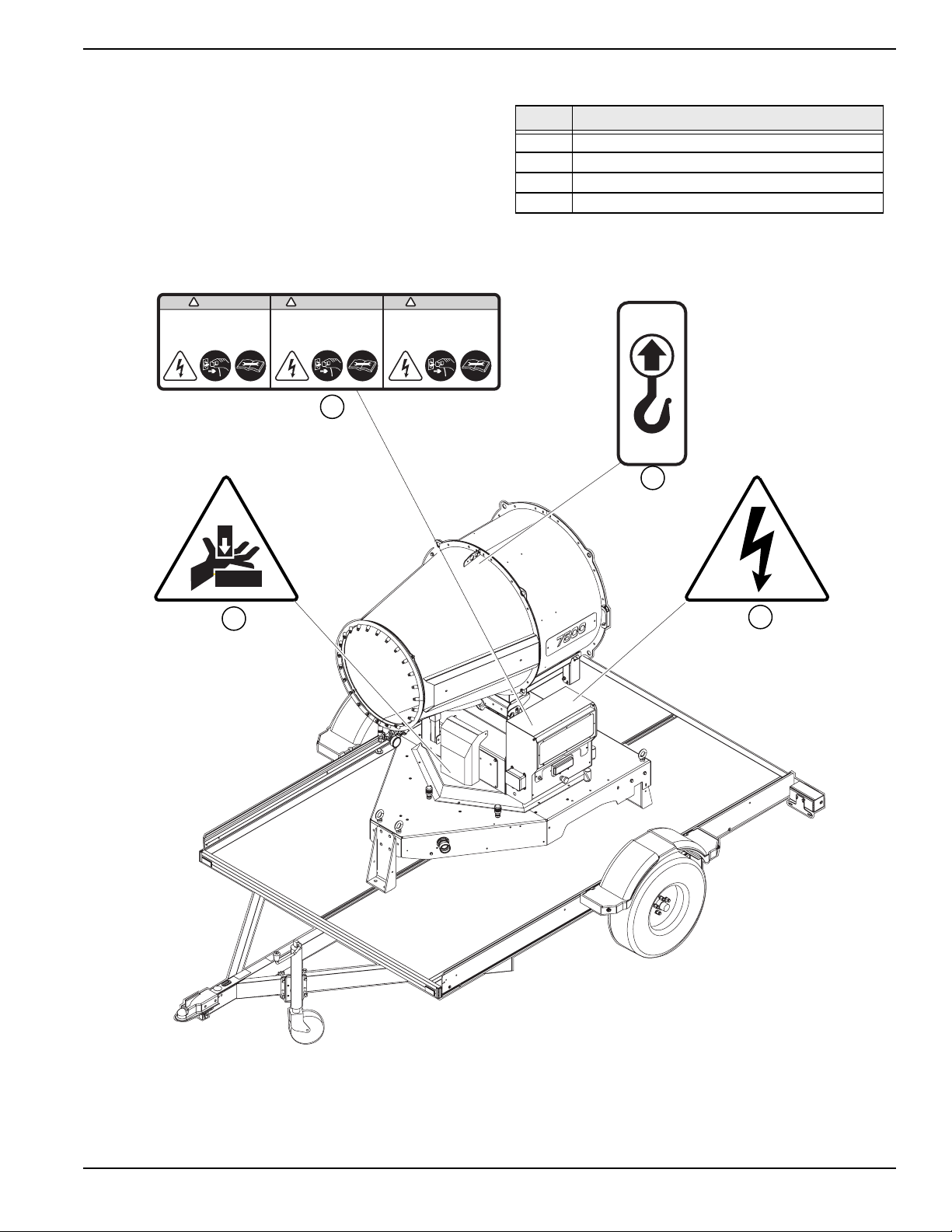
Safety and Operating Decals
This unit features numerous safety and operating decals.
These decals provide important operating instructions and
warn of dangers and hazards. The following diagrams
illustrate decal locations and descriptions.
Replace any missing or hard-to-read decals and use care
when washing or cleaning the unit. Decal part numbers
can be found in the parts manual at www.generacmobile-
products.com.
WARNING
Hazardous Voltage.
Electric shock may cause serious
injury or death.
Disconnect power before servicing.
! !!
AVERTISSEMENT
Tension Dangeureuse .
Une décharge électrique entraînera
des blessures graves, voire la mort.
Déconnecter le courant avant de
commencer le service.
1
ADVERTENCIA
Voltage Peligroso.
Las descargas eléctricas causan
Desde lesiones graves hasta la muerte.
Desconectar la fuente de poder antes
de hacer servicio
Table 1-1. Decal Descriptions
ID Description
1 Electric Shock Hazard
2 Central Lift Point
3 Electric Shock Hazard
4 Hand Crush
2
4
3
Figure 1-1. Safety Decal Locations
IMPORTANT NOTE: See original trailer operating manual for trailer safety and operating decal information.
Owner’s Manual for DF 7500 Dust Suppression System 5
Page 10

Introduction and Safety
This page intentionally left blank.
6 Owner’s Manual for DF 7500 Dust Suppression System
Page 11

General Information
Section 2: General Information
Specifications
Description Units DF7500
Electric Connection A Inlet plug three phase 32
Voltage V 240
Hertz Hz 32
Smallest Generator Required kW 32 three-phase
Fan Power kW 7.5
Pump Power kW 2.2
Water Connection - 1” hose barb
Water Consumption gal/min (L/min) 13.7 (52)
Inlet Pressure psi (bar) 1.45 (.1) - 5.8 (.4)
Inlet Water Filter micron/mesh 180/80
Number of Nozzles 24
Rotation Angle Range degrees 335
Tilt Angle degrees 0-40
Noise Level DB @ 22 ft (7 m) 84
Maximum Horizontal Range (without wind) ft (m) 98-131 (30-40)
Maximum Vertical Range (without wind) ft (m) 52 (16)
Maximum Covered Area acre (m2) 1.13 (4,600)
Weights
Skid Mounted lb (kg) 1,993 (904)
Trailer Mounted lb (kg) 2,373 (1,076)
Dimensions
Skid Mounted L x W x H ft (m) 10.83 (3.30) x 6 (1.83) x 7.15 (2.18)
Trailer Mounted L x W x H ft (m) 102 (31) x 178 (52) x 104 (32)
Specifications are subject to change without notice. Refer to the product specification sheet for complete list.
Unit Dimensions
A 6 ft (1.83 m)
B 10.83 ft (3.3 m)
C 7.15 (2.18)
A
Figure 2-1. Unit Dimensions
Owner’s Manual for DF7500 Dust Suppression System 7
C
B
009031
Page 12

General Information
Component Location
I
A
B
E
F
C
D
A
A
J
Figure 2-2. Component Locations
A Lifting Eye F Radio Control Receiver
B Nozzles G Water Inlet Filter
C Water Flow Control Valves H Water Inlet Connection
D Working Range Limiter Pins I Transport Safety Locks
E Control Panel J Electrical Socket
Control Panel
G
C
D
B
A
N
M
F
E
I
K
L
H
J
Control Panel Components and Functions
A Manual Control Switch
B Oscillation System Switch
C Hour Meter
D Water Pump Switch
E Fan Switch
F Phase Controller Error Lamp
G Phase Controller Switch
H Input Switch
I Button Emptying Water Circuit
J Blower Tilting Lever
K Fan Motor Protection Circuit Breaker
L Water pump Protection Circuit Breaker
M Emergency Stop Button
N Oscillation System Protection Circuit Breaker
G
H
009032
Figure 2-4. Control Panel
8 Owner’s Manual for DF7500 Dust Suppression System
Page 13

General Information
Transmitter Unit
C
A
B
D
I
G
Figure 2-4. Transmitter Unit
Unit and Serial Number Locations
See Figure 2-5 to locate the unit ID tag (A) and vehicle
identification number (VIN) tag (B). Important information
such as the unit model number, serial number, VIN, and
tire loading information are listed on these tags. Record
the information from these tags in the event the tags are
lost or damaged. This information may be needed when
ordering parts or requesting assistance
L
E
F
J
H
K
Transmitter Unit Components and Functions
A Fan ON
B Fan OFF
C Pump ON
D Pump OFF
E Oscillation system ON
F Oscillation system OFF
G Fan and pump ON
H All devices OFF
I Tilting Up
J Tilting Down
K Main ON-OFF switch (on back)
L Transmission battery status
Connecting Water Supply
WARNING
Personal injury. Only use water from controlled, reliable
sources. Uncontrolled water could contain bacteria. Inhaling
mist containing bacteria could result in death, or serious
injury.
(000584)
B
A
009111
Figure 2-5. Unit and Serial Number Locations
NOTE: DO NOT run unit without sufficient water supply.
Failure to follow water supply requirements will void
warranty.
Water supply must meet the following requirements:
• Water must be greater than 15 gallons per minute
(52 liters per minutes) and no less than 14 psi (1
bar).
• Water supply hose length must not exceed 50 ft
(15.2 m).
• Water temperature must be less than 100°F
(38°C).
• DO NOT siphon standing water for the water
source.
• Use only controlled water from reliable sources.
• DO NOT use a one-way valve, vacuum breaker, or
check valve in any part of the water supply.
Owner’s Manual for DF7500 Dust Suppression System 9
Page 14

General Information
1. Run water 30 seconds prior to connection to eliminate debris.
2. See Figure 2-6. Connect a hose to 1” water inlet
(A) and hand-tighten.
A
009111
Figure 2-6. Water Connection
Connecting Power Supply
DANGER
Electrocution. In the event of electrical accident,
immediately shut power OFF. Use non-conductive
implements to free victim from live conductor. Apply
first aid and get medical help. Failure to do so will
result in death or serious injury.
(000145)
IMPORTANT NOTE: See generator operator’s manual
for proper installation procedure to generator.
1. Install power cable wires (A) to three phase, 240
volt power source.
A
009116
Figure 2-7. Electrical Connection
2. See Figure 2-10. Verify input switch (B) is in the
OFF position.
3. Verify emergency stop button (C) is in the out
armed position. If the emergency stop button is
engaged, twist the emergency stop button clockwise to release.
DANGER
Electrocution. Verify electrical system is
properly grounded before applying power.
Failure to do so will result in death or serious
injury.
(000152)
DANGER
Electrocution. Water contact with a power
source, if not avoided, will result in death
or serious injury.
(000104)
DANGER
Electrocution. Turn utility and emergency
power supplies to OFF before connecting
power source and load lines. Failure to do so
will result in death or serious injury.
(000116)
WARNING
Electric shock. Only a trained and licensed electrician
should perform wiring and connections to unit. Failure
to follow proper installation requirements could result in
death, serious injury, and equipment or property damage.
(000155a)
B
C
008780
Figure 2-8. Emergency Stop Button
4.
See
Figure 3-4
. Connect power cable to socket (D)
IMPORTANT NOTE: Installations must be comply
with national, state, and local codes.
10 Owner’s Manual for DF7500 Dust Suppression System
Figure 2-9. Electrical Connection
D
008950
Page 15

General Information
Using Transport Locks
See Figure 2-10. Transport locks (A) (B) must be
disengaged prior to operation
IMPORTANT NOTE: Verify transport locks are
engaged prior to transporting the unit.
Disengaging Transport Locks
1. Remove transport locking pin (A) from transport
lock support.
2. Lift transport locking pin (B) to raised position
Engaging Transport Locks
1. Shut off manual oscillation. See Control Panel.
2. Lower blower completely. See Control Panel.
3. See Figure 2-10. Align holes in actuator supports
(A).
4. Insert transport locking pin through holes (A) and
secure with cotter pin.
5. Rotate blower to forward position.
6. Insert transport lock (B) into hole in base.
Lifting the Unit
WARNING
Personal injury. Failure to properly connect
lifting cables, chains, or straps could result in
death, serious injury, or property damage.
(000346)
WARNING
Personal Injury. Do not use lifting eye if there are signs
of damage or corrosion. Doing socould result in death,
serious injury, or property damage.
(000433)
WARNING
Personal Injury. Do not use lifting eye other than as
directed. Doing so could result in death, serious injury,
or property damage.
(000434)
WARNING
B
A
008784
Figure 2-10. Transport Locks
Towing the Unit (if equipped)
See trailer operator’s manual for proper towing setup and
procedure.
Personal Injury. Verify all fasteners are properly
tightened prior to lifting unit. Failure to do so could
result in death, serious injury, or property damage.
(000351)
1. Verify equipment being used to lift the unit is in
good condition and has sufficient capacity. For
approximate weights, refer to Specifications.
2. Engage transport locks. See Using Transport
Locks.
3.
Remain aware of people and objects around the unit
while preparing, maneuvering, and lifting the unit.
• When lifting the unit, attach any slings, chains, or
hooks directly to the four lifting points (A). The
central lift point is located on top of the enclosure,
connected to a lift structure inside the unit.
• Use fork lift pockets (B) with care. Avoid
approaching unit at an angle as this can damage
the forklift pockets. Verify obstructions are clear of
the forklift tines before lifting.
A
A
B
Figure 2-11. Lifting Points
Owner’s Manual for DF7500 Dust Suppression System 11
008776
Page 16

General Information
This page intentionally left blank.
12 Owner’s Manual for DF7500 Dust Suppression System
Page 17

Section 3: Operation
)
g
Operation
DANGER
Electrocution. In the event of electrical accident,
immediately shut power OFF. Use non-conductive
implements to free victim from live conductor. Apply
first aid and get medical help. Failure to do so will
result in death or serious injury.
(000145)
DANGER
Electrocution. Verify electrical system is
properly grounded before applying power.
Failure to do so will result in death or serious
injury.
(000152)
DANGER
Electrocution. Water contact with a power
source, if not avoided, will result in death
or serious injury.
(000104)
WARNING
Consult Manual. Read and understand manual
completely before using product. Failure to
completely understand manual and product
could result in death or serious injury.
(000100a)
Operation and Use Questions
Contact your nearest Generac Mobile Products Authorized
Service Dealer (ASD), or contact Generac Mobile Products
Technical Service at 1-800-926-9768 or
www.generacmobileproducts.com with any questions or
concerns about unit operation and maintenance.
Before Starting
1. Place unit on flat ground in a well ventilated area.
2. Place barriers 6 ft (2 m) around unit to prevent
unauthorized personnel from nearing unit.
3. See Figure 3-1. Verify sufficient water supply is
properly connected to water inlet (A). For water
requirements, see Connecting Water Supply.
WARNING
CAUTION
Equipment damage. Do not attempt to start or operate
a unit in need of repair or scheduled maintenance.
Doing so could result in serious injury, death, or
equipment failure or damage.
(000291)
WARNING
Before servicing unit, shut unit down, turn water supply
OFF, and disconnect unit from power source. Failure
to do so could result in death, serious injury, or
equipment damage.
(000586)
WARNING
Personal injury. Keep people and pets away from work
area. Failure to do so could result in death or serious
injury.
(000420)
WARNING
Personal injury. Only use water from controlled, reliable
sources. Uncontrolled water could contain bacteria. Inhalin
mist containing bacteria could result in death, or serious
injury.
(000584
A
009111
Figure 3-1. Water Connection
4. Turn on water supply.
5. See Figure 3-4. Open water control valves (B).
B
008796
Figure 3-2. Water Control Valves
Owner’s Manual for DF7500 Dust Suppression System 17
Page 18

Operation
6. See Figure 3-3. Verify power source is properly
connected to socket (C). For power requirements
and setup, see Connecting Power Supply.
C
008950
Figure 3-3. Electrical Connection
IMPORTANT NOTE: For grounding requirements, follow National Electrical Code (NEC), state, and local regulations.
7. See Figure 3-4. Verify transport lock (D) and (E)
are disengaged. For more information, see Using
Transport Locks.
H
G
F
E
C
A
D
B
I
008780
Figure 3-5. Control Panel
Stopping the Unit
NOTE: See Figure 3-5. Stop the unit at any time by
pressing emergency stop (A).
Shut down the unit in the following sequence:
1. Shut off oscillation system (F).
2. Shut off water pump (E).
3. Shut off fan (D).
4. Shut off input switch on control panel (B).
B
A
008784
Figure 3-4. Transport Safety Locks
Starting the Unit
1. See Figure 3-5. Verify emergency switch (A) is in
the out, armed position. If emergency switch is not
armed, twist counterclockwise to reset.
2. Turn input switch (B) ON.
3. Set manual control switch (C) to MANUAL.
4. Press fan (D) ON.
5. Press water pump (E) ON.
6. If using automatic oscillation system, press
oscillation system (F) ON.
NOTE: If using automatic oscillation, system must be set
up prior to operation. See Automatic Oscillation.
Tilting the Blower
NOTE: Transport locks must be disengaged before tilting
the blower. See Using Transport Locks.
See Figure 3-5. Use control panel tilting lever (I) or
remote control tilt buttons to adjust tilt 0 to 40°.
Manual Rotation
NOTE: Transport locks must be disengaged before
rotating blower. See Using Transport Locks.
1.
See
Figure 3-5
2. See Figure 3-6 Use handle (A) to rotate blower.
. Verify oscillation is switched OFF (F).
A
NOTE: If the fan does not start and phase controller
error lamp (G) is lit, turn phase controller switch (H) to
PHASE SRT or PHASE SRT then restart fan.
18 Owner’s Manual for DF7500 Dust Suppression System
Figure 3-6. Manual rotation
009116
Page 19

Operation
Automatic Oscillation
NOTE: Transport locks must be disengaged before
using oscillation system. See Using Transport Locks.
See Figure 3-7. When the oscillation system is set to
ON, blower rotation is controlled by the placement of
limiting pins (A). Oscillation range can be adjusted by
moving limiting pins to any hole (B) in the deck. When
micro switch (C) contacts a limiting pin the blower
reverses direction.
C
A
Figure 3-7. Automatic Oscillation
1. Turn OFF oscillation system. See Control Panel.
2. Manually rotate blower to the extreme the blower
should rotate to the left.
3. Install limiting pin (B) into nearest hole (B) to the
left of micro switch (C).
4. Manually rotate blower to the extreme the blower
should rotate to the right.
5. Install limiting pin (B) into nearest hole (B) to the
right of micro switch (C).
6. Turn ON oscillation system. See Control Panel.
B
008805
NOTE: If radio control fails at any time, switch control
switch (A) to MANUAL CONTROL.
1. See Figure 3-8. Move control switch (A) to RADIO
CONTROL.
2. Verify emergency switch (B) is in the out, armed
position. If emergency switch is not armed, twist
counterclockwise to reset.
A
B
008780
Figure 3-8. Control Panel
3. See Figure 3-9. Switch main on-off switch (A) on
back of transmitter to ON.
G
B
F
C
D
E
NOTE: When shutting down the unit, switch off
G
automatic oscillation first. See Stopping the Unit for
proper shutdown sequence.
Using the Transmitter
The operator using the radio control system must:
• Understand transmitter and machine functions.
• Visually follow machine movements activated by
transmitter.
• Switch off transmitting unit whenever suspending
the job.
Figure 3-9. Transmitter
4.
Select fan on/off (B), pump on/off (C), oscillation on/
off (D), tilting up/down (E), or fan and pump on (F).
NOTE: If LED (G) does not flash or flashes weakly when
a button is pressed, the battery needs to be replaced.
A
009034
• Remember the transmitter can activate machine
movements even in indoor locations away from the
receiving unit.
• Never leave the transmitter unattended.
• Avoid using radio control inside shielded areas.
NOTE: Pushing the stop button on the control panel
immediately disables all radio control.
5. Use macro button (G) to automatically switch off
oscillation, pump, and fan in the proper shutdown
sequence.
• Replace batteries when discharged.
Owner’s Manual for DF7500 Dust Suppression System 19
Page 20

Operation
This page intentionally left blank.
20 Owner’s Manual for DF7500 Dust Suppression System
Page 21

Maintenance and Troubleshooting
)
Section 4: Maintenance and Troubleshooting
Preparing for Service
WARNING
Before servicing unit, shut unit down, turn water supply
OFF, and disconnect unit from power source. Failure
to do so could result in death, serious injury, or
equipment damage.
(000586
CAUTION
Equipment Damage. Failure to perform a daily
inspection could result in damage to the unit.
(000306)
Daily Walk-Around Inspection
Perform a walk-around inspection of the unit every day
before starting the unit. Look for conditions that could
hinder performance or safety, such as (but not limited to)
damaged or missing parts and hardware, and loose or
broken electrical connections.
General Maintenance
Maintenance
Activity
Clean Unit
Rinse Nozzles
Empty Water Circuit
Clean Water Filter
Lubricate Unit
Clean Nozzles
Before
Each Use
After
Each Use
Semi-
Annually
Before servicing the unit, always follow the instructions
listed below.
1. Verify unit power switch is OFF.
2. Disconnect power.
3. Disconnect water supply.
4. Attach a DO NOT USE sign to the control panel.
This will notify everyone that the unit is being
serviced and will reduce the chance of someone
inadvertently trying to start the unit.
Inspecting the Unit
If the unit is stored outside, check for water inside
•
the cabinet and control panel cover before each
use. If wet, dry the unit thoroughly before starting.
• Inspect condition of electrical cords. DO NOT use
the unit if insulation is cut or worn through.
Cleaning the Unit
Always clean the unit after each use to remove dust,
grease, mud or spilled fuel or oil. fter each use, clean the
unit if dust, grease, or dirt. Use soft, clean rags to wipe
the cabinet exterior and control panel. Low-pressure
compressed air (less than 40 PSI [276 kPa]) can also be
used to remove dust and debris from control panel.
NOTE: Do not use a high pressure hose or power
washer to clean control panel or cabinet. Water could
damage the electronic components.
Rinsing nozzles
See
Figure 4-1
antilimestone solution to prevent nozzle fouling.
. After each use, rinse nozzles (A) with an
Poorly maintained equipment can become a safety
hazard. In order for the equipment to operate safely and
properly over a long period of time, periodic maintenance
and occasional repairs are necessary. DO NOT perform
routine service unless all electrical components are OFF.
Regular maintenance will improve performance and
extend engine/equipment life. Generac Mobile Products,
LLC recommends all maintenance work be performed by
an Generac Mobile Products Authorized Dealer (ASD).
Figure 4-1. Cleaning the Unit
Owner’s Manual for DF7500 Dust Suppression System 21
A
Page 22

Maintenance and Troubleshooting
Emptying Water Circuit
After each use, empty the water system must to remove
sediment from the inlet filter and to prevent fouling.
See
See
Figure 4-3
Figure 4-3
1.
2.
open inlet valve (C).
. Open nozzle valves (A).
A
008796
Figure 4-2. Open Valves
. Disconnect hose from inlet (B) and
B
A
Figure 4-4. Inlet Water Filter
Cleaning Nozzle Filter
1.
See
Figure 4-3. Remove nozzle filter plug (C).
2. Remove filter cartridge.
3. Tap cartridge on a solid surface and blow with com-
pressed air to remove sediment.
4. Install cartridge and replace inlet filter plug.
008957
B
C
008796
Figure 4-3. Disconnect Hose and Open Valve
3. Allow system to drain.
4. Close inlet valve.
5. Close nozzle valves.
Cleaning Water Filters
The unit is equipped with an inlet filter and nozzle filter.
Both must be cleaned semiannually or whenever
performing system maintenance.
Cleaning Inlet Filter
1.
See
Figure 4-5. Unscrew and remove water inlet (B).
2. Remove filter cartridge.
3. Tap cartridge on a solid surface and blow with com-
pressed air to remove sediment.
4. Install cartridge and replace inlet filter plug.
C
008957
Figure 4-5. Nozzle Water Filters
Nozzle Cleaning
Clean nozzles on a semiannual basis or whenever
clogged.
1.
See
Figure 4-1. Remove nozzles (A) from blower.
2. Soak nozzles in antilimestone solution over night.
3. Rinse nozzles.
4. Reinstall nozzles
Figure 4-6. Cleaning Nozzles
.
A
22 Owner’s Manual for DF7500 Dust Suppression System
Page 23

Maintenance and Troubleshooting
Lubrication
See
Figure 4-1. Lubricate transport support (A) and
thrust bearing (B) on a semiannual basis.
Trailer Maintenance (if equipped)
Jack Maintenance See the original equipment’s
operating manual for maintenance schedule and a
complete list of maintenance requirements.
IMPORTANT NOTE: Failure to comply with the procedures and requirements as described in the trailer
operators manual will nullify the warranty, decrease
A
A
B
performance, and cause equipment damage or premature equipment failure.
Figure 4-7. Lubrication
General Troubleshooting
This information is intended to be a check or verification for simple causes that can be located and fixed. It does not
cover all types of problems. See the engine operator’s manual for additional troubleshooting information. Procedures
that require in-depth knowledge or skills should be performed by a GMP ASD.
Problem
Water Pump Doesn’t
Work
Fan and Pump do Not
Work
Possible Cause Solution
Open main water tap.
Pump dry
Open water control valves.
Air in water system
Verify sufficient water supply. See for requirements
Insufficient water inlet
pressure
Plug not correctly connected
Emergency stop button is
pressed
Main switch set to OFF
Pump or fan circuit protection breakers switched to
off.
Disconnected cables in the
electrical system
Dirty or obstructed nozzles
Improper start up sequence. The pump must be started prior to
opening the water flow and stopped before closing the water flow
Verify the plug properly fits into socket seat and is fastened by the
locking ring.
Verify the stop button is in the out, armed postion. If not turn the
knob clockwise.
Switch main switch to ON
Switch circuit protection breakers to ON
Inspect electrical system for disconnected plug.
Clean nozzles.
Uneven Nebulization
Tilt, Rotation or
Stabilizer Regulation
Difficult
Owner’s Manual for DF7500 Dust Suppression System 23
Low water pressure
Lack of lubrication Lubricate using proper grease for sliding systems.
Verify water pressure is greater than
requirements
.
14.5 psi (1 bar). See for
Page 24

Maintenance and Troubleshooting
This page intentionally left blank.
24 Owner’s Manual for DF7500 Dust Suppression System
Page 25

Maintenance and Troubleshooting
This page intentionally left blank.
Owner’s Manual for DF7500 Dust Suppression System 25
Page 26

Maintenance and Troubleshooting
This page intentionally left blank.
26 Owner’s Manual for DF7500 Dust Suppression System
Page 27

Page 28

Part No. 10000037626 Rev. A 11/15/2018
©2018 Generac Mobile Products, LLC
All rights reserved.
Specifications are subject to change without notice.
No reproduction allowed in any form without prior written
consent from Generac Mobile Products, LLC.
Generac Mobile Products, LLC
215 Power Drive, Berlin, WI 54923
GeneracMobileProducts.com │800-926-9768 │920-361-4442
 Loading...