

Generac Power Systems CorePower?/ES Generators, CorePower/ES Generator Installation Manuallines
Page 1
INSTALLATION
GUIDELINES
CorePower/ES Generators
THIS MANUAL MUST BE USED IN
CONJUNCTION WITH THE OWNERS
MANUAL.
www.generac.com or 1-888-GENERAC
NOT INTENDED FOR USE IN CRITICAL LIFE
SUPPORT APPLICATIONS.
ONLY QUALIFIED ELECTRICIANS OR CONTRACTORS
SHOULD ATTEMPT INSTALLATION!
DEADLY EXHAUST FUMES! OUTDOOR
INSTALLATION ONLY!
Page 2
Introduction .........................................................Inside Front Cover
Read this Manual Thoroughly ..............................................IFC
Contents ................................................................................1
Operation and Maintenance ....................................................1
How to Obtain Service ............................................................1
Safety Rules ...................................................................................1
Standards Index .....................................................................2
Unpacking/Inspection .....................................................................3
Before You Begin ............................................................................3
Unit Handling .................................................................................3
Minimum Clearance Requirements .................................................4
Site Preparation and Generator Placement ......................................5
Coverting to LP Vapor ....................................................................6
Installing & Connecting Gas Lines ..................................................6
External Electrical Connections .......................................................8
Battery Installation..........................................................................9
Automatic Transfer Switch Electrical Connections .........................10
Operational Testing .......................................................................12
Notes ...........................................................................................13
Installation Diagrams ....................................................................16
Thank you for purchasing this compact, high performance, aircooled, engine-driven generator. It is designed to automatically
supply electrical power to operate critical loads during a utility
power failure.
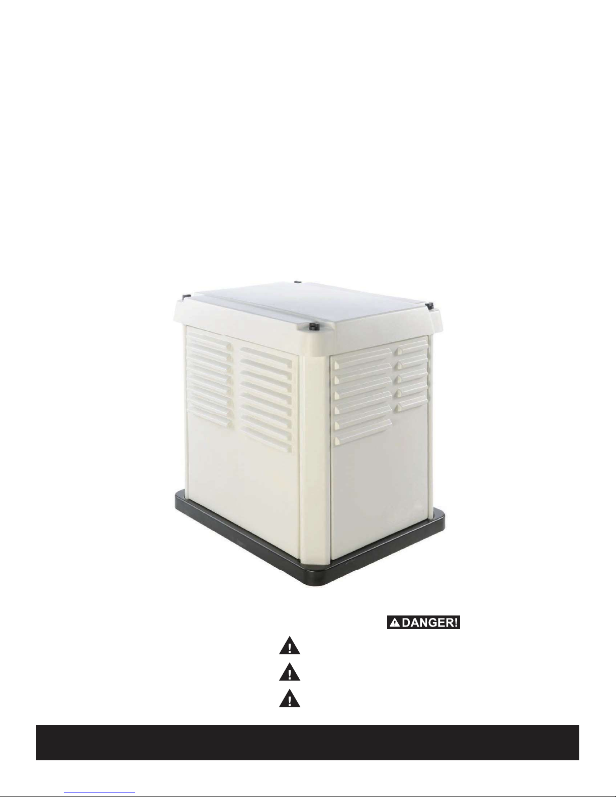
This unit is factory installed in an all-weather, composite enclosure
that is intended exclusively for outdoor installation. This
generator will operate using either vapor withdrawn liquid propane
(LP) or natural gas (NG).
NOTE:
This generator is suitable for supplying typical residential loads
such as Induction Motors (sump pumps, refrigerators, air conditioners, furnaces, etc.), Electronic Components (computer,
monitor, TV, etc.), Lighting Loads and Microwaves.
If any portion of this manual is not understood, contact the
nearest Dealer for starting, operating and servicing procedures.
Throughout this publication, and on tags and decals affixed to the
generator, DANGER, WARNING, CAUTION and NOTE blocks are
used to aler t personnel to special instructions about a particular
operation that may be hazardous if performed incorrectly or
carelessly. Observe them carefully. Their definitions are as follows:
INDICATES A HAZARDOUS SITUATION OR
ACTION WHICH, IF NOT AVOIDED, WILL RESULT
IN DEATH OR SERIOUS INJURY.
Indicates a hazardous situation or action which,
if not avoided, could result in death or serious
injury.
Indicates a hazardous situation or action which,
if not avoided, could result in minor or moderate
injury.
NOTE:
Notes contain additional information important to a procedure
and will be found within the regular text body of this manual.
These safety warnings cannot eliminate the hazards that they
indicate. Common sense and strict compliance with the special
instructions while performing the action or service are essential to
preventing accidents.
Four commonly used safety symbols accompany the DANGER,
WARNING and CAUTION blocks. The type of information each
indicates is as follows:
This symbol points out important safety information that,
if not followed, could endanger personal safety and/or
property of others.
This symbol points out potential explosion hazard.
This symbol points out potential fire hazard.
Page 3
This symbol points out potential electrical shock hazard.
The operator is responsible for proper and safe use of the
equipment. The manufacturer strongly recommends that
the operator read and thoroughly understand all instructions
before using this equipment. The manufacturer also strongly
recommends instructing other users to properly start and operate
the unit. This prepares them if they need to operate the equipment
in an emergency.
This manual contains pertinent installation information for model:
• 6 kW NG, 7 kW LP, single-cylinder OHV 432 Engine
It is the operator’s responsibility to perform all safety checks, to
make sure that all maintenance for safe operation is performed
promptly, and to have the equipment checked periodically by a
Dealer. Normal maintenance service and replacement of parts
are the responsibility of the owner/operator and, as such, are not
considered defects in materials or workmanship within the terms
of the warranty. Individual operating habits and usage contribute to
the need for maintenance service.
Proper maintenance and care of the generator ensures a minimum
number of problems and keep operating expenses at a minimum.
See a Dealer for service aids and accessories.
When the generator requires servicing or repairs, contact a Dealer
for assistance. Service technicians are factory-trained and are
capable of handling all service needs.
The manufacturer cannot anticipate every possible circumstance
that might involve a hazard. The warnings in this manual, and on
tags and decals affixed to the unit are, therefore, not all-inclusive.
If using a procedure, work method or operating technique the
manufacturer does not specifically recommend, ensure that it is
safe for others. Also make sure the procedure, work method or
operating technique utilized does not render the generator unsafe.
Despite the safe design of this generator,
operating this equipment imprudently,
neglecting its maintenance or being careless
can cause
possible injury or death. Permit only responsible and capable persons to install, operate
and maintain this equipment.
Potentially lethal voltages are generated by
these machines. Ensure all steps are taken to
render the machine safe before attempting to
work on the generator.
Parts of the generator are rotating and/or hot
during operation. Exercise care near running
generators.
Installation must always comply with applicable codes, standards, laws and regulations.
A running generator gives off carbon monoxide, an odorless, colorless poison gas.
Breathing in carbon monoxide can cause
headaches, fatigue, diziness, nausea, vomitting, confusion, fainting, siezures or death.
GENERAL HAZARDS
When contacting a Dealer about parts and service, always supply
the complete model number and serial number of the unit as given
on its data decal, which is located on the generator. See section
“The Generator” in the Owner’s Manual for decal location.
Model No.__________________ Serial No. ______________
Save These Instructions The manufacturer
suggests that these rules for safe operation
be copied and posted near the units installation site. Safety should be stressed to all
operators and potential operators of this
equipment.
Study these SAFETY RULES carefully before installing, operating
or servicing this equipment. Become familiar with this Owners
Manual and with the unit. The generator can operate safely,
efficiently and reliably only if it is properly installed, operated and
maintained. Many accidents are caused by failing to follow simple
and fundamental rules or precautions.
• Adequate, unobstructed flow of cooling and ventilating air
is critical to correct generator operation. Do not alter the
installation or permit even partial blockage of ventilation
provisions, as this can seriously affect safe operation of the
generator. The generator MUST be installed and operated
outdoors only.
• Keep hands, feet, clothing, etc., away from drive belts, fans,
and other moving or hot parts. Never remove any drive belt or
fan guard while the unit is operating.
CALIFORNIA PROPOSITION 65 WARNING
Engine exhaust and some of its constituents are known
to the State of California to cause cancer, birth defects
and other reproductive harm.
CALIFORNIA PROPOSITION 65 WARNING
This product contains or emits chemicals known to the
State of California to cause cancer, birth defects and
other reproductive harm.
1
Page 4

• When working on this equipment, remain alert at all times.
Never work on the equipment when physically or mentally
fatigued.
• Inspect the generator regularly, and contact the nearest Dealer
for parts needing repair or replacement.
• Before performing any maintenance on the generator,
disconnect its battery cables to prevent accidental start up.
Disconnect the cable from the battery post indicated by a
NEGATIVE, NEG or (–) first, then remove the POSITIVE, POS
or (+) cable. When reconnecting the cables, connect the
POSITIVE cable first, the NEGATIVE cable last.
• Never use the generator or any of its parts as a step. Stepping
on the unit can stress and break parts, and may result in
dangerous operating conditions from leaking exhaust gases,
fuel leakage, oil leakage, etc.
CARBON MONOXIDE HAZARDS
• The engine exhaust fumes contain carbon monoxide, which
can be DEADLY. This dangerous gas, if breathed in sufficient
concentrations, can cause unconsciousness or even death.
Do NOT alter or add to the exhaust system or do anything that
might render the system unsafe or in noncompliance with
applicable codes and standards.
• Install a battery operated carbon monoxide alarm indoors,
according to manufacturer’s instructions/recommendations.
ELECTRICAL HAZARDS
• All generators covered by this manual produce dangerous
electrical voltages and can cause fatal electrical shock. Utility
power delivers extremely high and dangerous voltages to
the transfer switch as does the standby generator when it
is in operation. Avoid contact with bare wires, terminals,
connections, etc., while the unit is running. Ensure all
appropriate covers, guards and barriers are in place, secured
and/or locked before operating the generator. If work must
be done around an operating unit, stand on an insulated, dry
surface to reduce shock hazard.
• Do not handle any kind of electrical device while standing
in water, while barefoot, or while hands or feet are wet.
DANGEROUS ELECTRICAL SHOCK MAY RESULT.
• The National Electrical Code (NEC) requires the frame and external
electrically conductive parts of the generator to be connected to
an approved earth ground. Local electrical codes also may require
proper grounding of the generator electrical system.
• After installing this home standby electrical system, the
generator may crank and start at any time without warning.
When this occurs, load circuits are transferred to the STANDBY
(generator) power source. To prevent possible injury if such
a start and transfer occur, always set the generator’s AUTO/
OFF/MANUAL switch to its OFF position before working on
equipment and remove the 7.5A fuse from the generator control
panel.
• In case of accident caused by electric shock, immediately shut
down the source of electrical power. If this is not possible,
attempt to free the victim from the live conductor. AVOID DIRECT
CONTACT WITH THE VICTIM. Use a nonconducting implement,
such as a dry rope or board, to free the victim from the live
conductor. If the victim is unconscious, apply first aid and get
immediate medical help.
2
• Never wear jewelry when working on this equipment. Jewelry
can conduct electricity resulting in electric shock, or may get
caught in moving components causing injury.
FIRE HAZARDS
• For fire safety, the generator must be installed and maintained
properly. Installation must always comply with applicable
codes, standards, laws and regulations. Adhere strictly
to local, state and national electrical and building codes.
Comply with regulations the Occupational Safety and Health
Administration (OSHA) has established. Also, ensure that the
generator is installed in accordance with the manufacturer’s
instructions and recommendations. Following proper
installation, do nothing that might alter a safe installation and
render the unit in noncompliance with the aforementioned
codes, standards, laws and regulations.
• Keep a fire extinguisher near the generator at all times.
Extinguishers rated “ABC” by the National Fire Protection
Association are appropriate for use on the standby electric
system. Keep the extinguisher properly charged and be
familiar with its use. Consult the local fire depar tment with any
questions pertaining to fire extinguishers.
EXPLOSION HAZARDS
• Do not smoke around the generator. Wipe up any fuel or oil
spills immediately. Ensure that no combustible materials are left
in the generator compartment, or on or near the generator, as
FIRE or EXPLOSION may result. Keep the area surrounding the
generator clean and free from debris.
• Gaseous fluids such as natural gas and liquid propane (LP)
gas are extremely EXPLOSIVE. Install the fuel supply system
according to applicable fuel-gas codes. Before placing the
home standby electric system into service, fuel system
lines must be properly purged and leak tested according to
applicable code. After installation, inspect the fuel system
periodically for leaks. No leakage is permitted.
In the absence of pertinent standards, codes, regulations and
laws, the published information listed below may be used as
installation guide for this equipment.
1. NFPA No. 37, STATIONARY COMBUSTION ENGINES AND GAS
TURBINES, available from the National Fire Protection Association,
470 Atlantic Avenue, Boston, MA 02210.
2. NFPA No. 76A, ESSENTIAL ELECTRICAL SYSTEMS FOR HEALTH
CARE FACILITIES, available same as Item 1.
3. NFPA No. 54, NATIONAL FUEL GAS CODE, available same as Item
1.
4. NFPA No. 58, AMERICAN NATIONAL STANDARD FOR STORAGE
AND HANDLING OF LIQUEFIED PETROLEUM GAS, available same
as Item 1.
5. NFPA No. 70, NFPA HANDBOOK OF NATIONAL ELECTRIC CODE,
available same as Item 1.
6. Article X, NATIONAL BUILDING CODE, available from the American
Insurance Association, 85 John Street, New York, N.Y. 10038.
7. AGRICULTURAL WIRING HANDBOOK, available from the Food and
Energy Council, 909 University Avenue, Columbia, MO 65201.
Page 5
8. ASAE EP-3634, INSTALLATION AND MAINTENANCE OF FARM
STANDBY ELECTRICAL SYSTEMS, available from the American
Society of Agricultural Engineers, 2950 Niles Road, St. Joseph, MI
49085.
9. NFPA No. 30, FLAMMABLE AND COMBUSTIBLE LIQUIDS CODE,
available same as Item 1.
Fully comply with all relevant NEC, NFPA and OSHA standards
as well as all federal, state and local building and electric codes.
As with any generator, this unit must be installed in accordance
with current NFPA 37 and NFPA 70 standards as well as any other
federal, state, and local codes for minimum distances from other
structures.
Only qualified electricians or contractors
should attempt such installations, which must
comply strictly with applicable codes, standards and regulations.
After unpacking, carefully inspect the contents for damage.
• This standby generator set is ready for installation with a factory
supplied and pre-mounted base pad and has a weather protective
enclosure that is intended for outdoor installation only.
• This UL listed standby generator set is packaged with an
automatic transfer switch with built in load center.
• This UL listed, 2-pole transfer switch is rated at 50A AC
amperes at 250 volts maximum.
If this generator is used to power electrical load
circuits normally powered by a utility power
source, it is required by code to install a transfer switch. The transfer switch must effectively
isolate the electrical system from the utility distribution system when the generator is operating (NEC 700, 701 & 702). Failure to isolate an
electrical system by such means will result in
damage to the generator and also may result in
injury or death to utility power workers due to
backfeed of electrical energy.
If any loss or damage is noted at time of delivery, have the
person(s) making the delivery note all damage on the freight bill
or affix their signature under the consignor’s memo of loss or
damage.
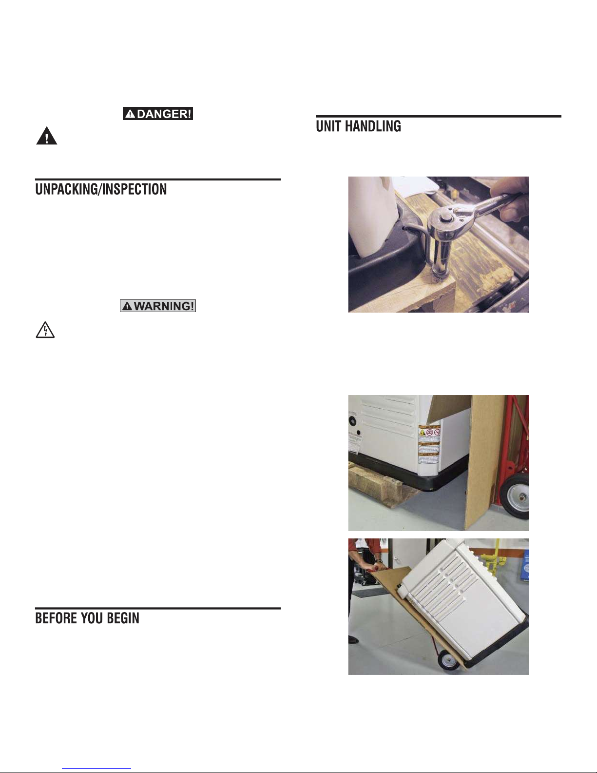
1. Once the generator has been unpacked. To remove it from
the wooden shipping pallet, remove the four lag bolts and
shipping brackets from the four corners of the base.
2. DO NOT ATTEMPT TO MOVE THE UNIT BY PULLING OR
LIFTING ON THE ROOF OF THE ENCLOSURE.
3. Using the sides of the enclosure slide the generator to one
edge of the wooden pallet.
4. Cut off one side panel of the shipping carton to use as a
protective barrier.
If a loss or damage is noted after delivery, separate the damaged
materials and contact the carrier for claim procedures.
“Concealed damage” is understood to mean damage to the
contents of a package that is not in evidence at the time of
delivery, but is discovered later.
To properly open the roof, press down on the center top lip and
release the latch. If pressure is not applied from the top, the roof
may appear stuck. Always verify that the side lock is unlocked
before attempting to lift the roof.
Contact the local inspector or City Hall to be aware of all federal,
state and local codes that could impact the installation. Secure all
required permits before starting the job.
Carefully read and follow all of the procedures and safety
precautions detailed in the installation guide. If any portion of the
installation manual, technical manual or other factory-supplied
documents is not completely understood, contact a dealer for
assistance.
5. Using a 2 wheeled hand truck place the cardboard between
the hand truck and the generator enclosure. Slide the
generator off the wooden pallet onto the hand truck. Wheel
the generator to the installation location.
3
Page 6
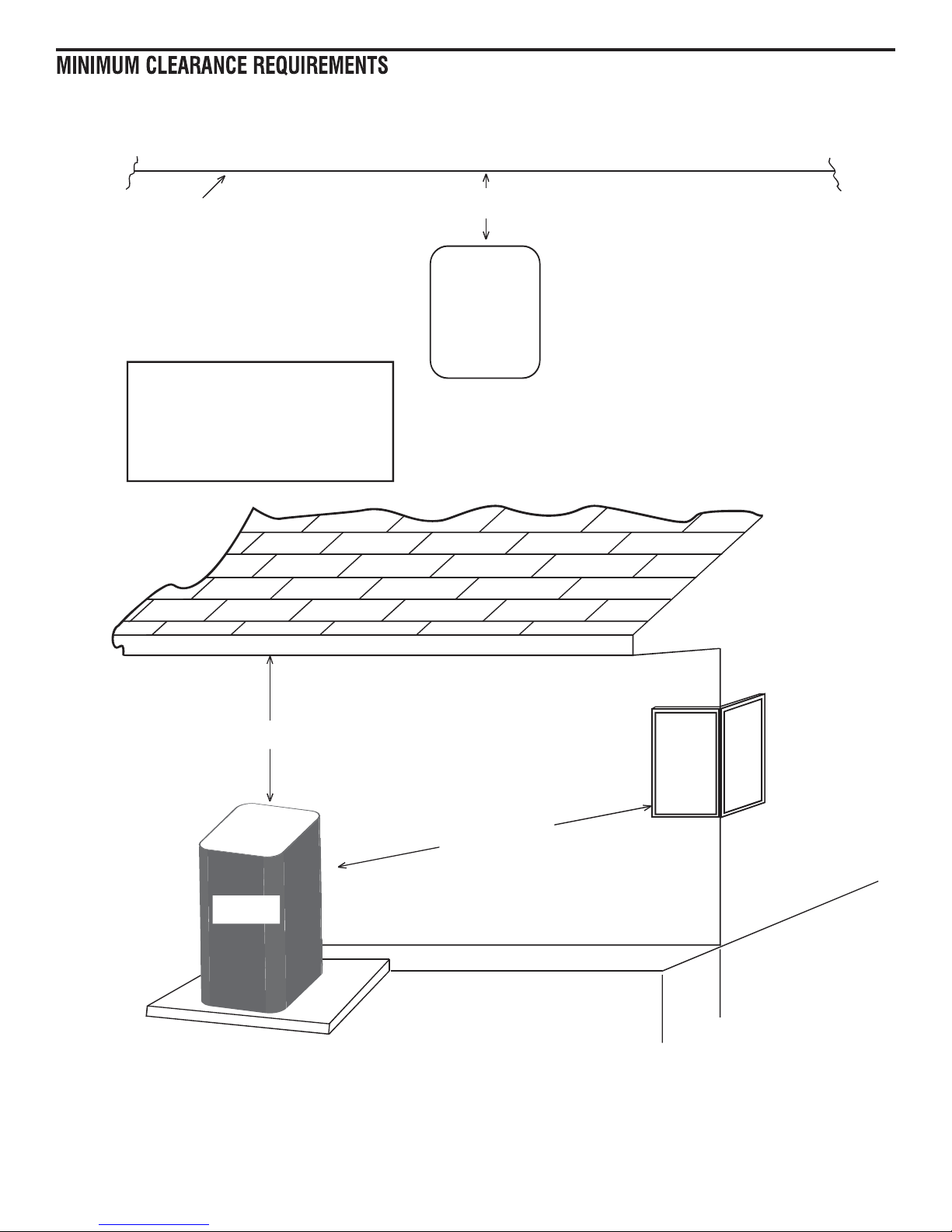
No windows or openings in the wall permitted
within 5 feet from any point of the generator.
Existing Wall
36” if the surface has a fire resistant rating of at least one hour per NFPA 37
These guidelines are based upon the
requirements of NFPA 37 and the
manufacturer’s requirement for air flow
for proper operation. Local codes may
be different and more restrictive than
what is described here.
60 inches Minimum Distance All Around
Top of Generator
Clearance from the ends and front of the generator
should be 36” minimum per NFPA 37. This would
include shrubs, trees and any kind of vegetation.
Clearance at the top should be a minimum of 60
inches from any structure, overhang or projections
from the wall. The generator should not be placed
under a deck or other structure that is closed in and
would limit or contain air flow.
60” Minimum
60” Recommended
Minimum From Ends
Generator
NOTE:
Failure to follow these minimum clearance guidelines may result in the generator failing inspection by the local
building, electrical or fire inspector requiring the generator be reinstalled in the correct location.
4
Page 7

1. Locate the mounting area as close as possible to the transfer
switch and fuel supply.
Leave adequate room around the area for service access
(check local code), and place high enough to keep rising
water from reaching the generator.
Choose an open space that will provide adequate and
unobstructed airflow. Do not install under or too close to
partially enclosed spaces including, but not limited to, decks
or buildings.
3. Set the generator onto the pad so that the gravel bed extends
several inches beyond the generator on all sides.
Make sure the generator is level within ½ inch.
4. The engine generator is to be grounded in accordance with
the NEC and local electrical codes.
Oil Dipstick
and Fill
Oil Drain
Hose
2. Place the unit so air vents won’t become clogged with leaves,
grass, snow or debris. Make sure exhaust fumes will not enter
the building through eaves, windows, ventilation fans or other
air intakes.
Dig a rectangular area approximately five inches deep and
about six inches longer and wider than the footprint of the
generator. Cover with polyurethane film and fill with pea gravel
or crushed stone. Compact and level the stone. A concrete
pad can be poured, or a Gen-Pad can be purchased if desired.
5. Check the engine oil and, if necessary, add enough of the
recommended oil to bring the level up to the FULL mark on
the dipstick. Be careful not to overfill the crankcase.
5
Page 8

1. Remove the generator enclosure roof by turning the four
quarter turn latches on the roof top. Push down slightly on the
latch then turn 90 degrees to release. The latch should pop up
as shown.
5. To change the fuel selection, remove the hose clamp and
hose from the throttle assembly.
6. Remove the Natural Gas (Larger ID) fuel jet from the fuel inlet.
7. Obtain the fuel jet for Propane (Smaller ID that has been
supplied loose with the owners manual).
8. Verify that the O-ring, supplied loose with the owners manual
is installed, into the groove of the fuel jet.
9. Insert the Propane fuel jet into the end of the fuel inlet.
10. Reinstall the hose and clamp onto the fuel inlet and secure.
11. Verify the hose has not been kinked in any way.
\2. Remove the two side panels of the enclosure by lifting the
panels straight up until they are clear.
3. Carefully place the roof and side panels to one side.
4. Locate the fuel throttle assembly mounted to the engine
intake.
*YIP-RPIX
36MRKMRWXEPPIH
8LVSXXPI
%WWIQFP]
*YIP.IX
6IKYPEXSV
,SWI
,SWI'PEQT
12. The generator is now ready to run on LP Vapor fuel.
Remove Clamp
and Hose
6
1. Both natural gas and LP Vapor are highly volatile substances,
so strict adherence to all safety procedures, codes, standards
and regulations is essential.
Gas line connections should be made by a certified plumber
familiar with local codes. Always use AGA-approved gas pipe
and a quality pipe sealant or joint compound.
Verify the capacity of the natural gas meter or the LP tank in
regards to providing sufficient fuel for both the generator and
other operating appliances.
Page 9

2. Most applications will require an external manual full flow
shutoff valve on the fuel line.
3. Where the gas line is to enter the generator enclosure. Install
a 3 - 5“ long piece of ½” black iron pipe threaded at both
ends (Not provided). Thread one end into the generator fuel
regulator using the reducing bushing provided. On the other
end of the pipe thread a ½” standard pipe Tee as shown (Not
provided).
6. When connecting the gas line to the generator, use the
provided section of UL Listed or AGA-approved flexible fuel
line in accordance with local regulations. The purpose of the
flexible fuel line is to ensure that vibration from the generator
does not cause a gas leak at one of the connection points, so
it’s important that the line be installed with as few bends as
possible.
7. Never bend the flexible fuel line to avoid using an elbow.
Bending the flexible line decreases its ability to absorb
vibrations and defeats its purpose as well as constricts the
actual fuel flow.
8. After checking for leaks, check the gas pressure at the
regulator to make sure there’s enough pressure for proper
generator operation.
The local gas supplier is responsible for ensuring adequate
pressure, so if the pressure is too low, or if it’s greater than
14 inches of water column, contact the gas supplier.
Correct static fuel pressure should be:
• Natural Gas = 5-7 inches water column
• LP = 10-12 inches water column
Measure fuel
pressure here.
9. When finished checking the gas pressure, close the manual
shutoff valve.
4. Make sure the center leg of the Tee is pointing straight down
when fully tightened onto the pipe.
5. Thread a 3 – 4” long piece of ½” black iron pipe threaded
at both ends (not provided) into the Tee Fitting. Fully tighten.
Thread a ½” Pipe cap (not provided) to the other end of the
pipe. Fully tighten. This downward pointing pipe will serve as
a water and sediment trap and should be periodically emptied
once the generator is in service.
7
Page 10

1. Electrical Connections to the generator are to be made inside
the main output circuit breaker panel. The connections will
consist of the following:
• 2 x Ungrounded conductors – Minimum wire size use 75
Deg C, 300V wire, 10AWG Copper.
• 1 x Grounded Conductor - Minimum wire size use 75 Deg
C, 300V wire, 10AWG Copper.
• 1 x Equipment Grounding Conductor - Minimum wire size
use 75 Deg C, 300V wire, 10AWG Copper.
• 6 x Control Wires – Use 75 Deg C, 300V wire, 14AWG
Copper.
NOTE:
Either use different colored wires or identify both ends of the
wires for easy connection of all wires to the Transfer Switch.
NOTE:
Local codes may require the control wires to be run in a separate conduit than the power wires.
• Use Class 1 wiring methods.
• These conductors should be fed through ¾” Flexible Liquidtight conduit for easy connection to the generator.
2. Remove the dead front plate from the output circuit breaker
panel. Retain fastener and external tooth washer for
reassembly.
5. Support the conduit connector plate up towards the output
circuit breaker. Make all the required wiring connections to the
Circuit breaker, Neutral Bar, Ground bar and Terminal strips
as described on the decal on the back side of the dead front
plate.
NOTE:
In order to maintain separation of circuits, the DC control wires
must be separated from the AC control wires. A piece of fiberglass sleeving has been provided in the manual kit to achieve
this. Slide the sleeving over the AC wires OR the DC wires, but
not both. Sleeving should extend over the wires from the conduit
connector in the conduit plate up to the terminal blocks.
3. Remove the conduit connector plate from the output circuit
breaker panel. Remove the plastic hole plug from the conduit
connector plate.
4. Pass all wires through hole in conduit connector plate, insert
conduit connector, and place lock nut onto conduit connector.
Fully tighten locknut.
8
6. Once all connections are made, reattach the conduit
connector plate to the output circuit breaker panel making
sure no wires are trapped behind the panel.
Page 11

7. Reattach the dead front plate to the output circuit breaker
panel with hardware removed in Step 1. Make sure to
reconnect the grounding wire.
8. Insert the padlock hasp that is supplied loose with the
generator through the slot in the dead front plate. Push the
padlock hasp back until it clicks and locks into place.
The correct size battery for this generator that will fit easily and
provide the required star ting ability is any maintainable automotive
style group 26R with a minimum of 525 CCA @ 0 deg F.
Before attempting to install the battery make
sure the auto/off/manual switch is in the off
position. Remove the main fuse from the
control panel.
Remove fuse!
9. To complete the external electrical connections snap in the
output circuit breaker cover that is supplied loose with the
generator into the output circuit breaker panel. Allow the cover
to swing down providing weather protection for the circuit
breaker.
The padlock hasp will now protrude through the circuit
breaker cover and it is recommended that once installation
of the generator is completed a padlock be used to provide
suitable security to the generator.
2. Rest the battery on the base of the generator and make the
battery connections. Connect battery positive (red) first then
battery negative (black). Install the plastic battery covers
supplied loose with the generator.
9
Page 12

3. Slide the battery under the rubber air in duct until it drops into
the holding well in the generator base. It may be necessary
to gently lift up the bottom edge of the rubber air in duct to
allow the battery to pass underneath until it drops into its final
location.
4. Once the battery is in place double check that the rubber air in
duct has not been displaced and is still fully connected at both
ends.
2. Connect the utility supply from the 50A 2-pole circuit breaker
in the main distribution panel to the terminals in the transfer
switch marked – Utility Source Connection.
NOTE:
Make sure the 50A Circuit Breaker remains OPEN or OFF at this
time.
Utility voltage is potentially leathal. It is
strongly recommened that the electrical portion of this installation be performed by a
qualified electrician.
Local code enforcement may require that AFCI’s be incorporated
into the transfer switch distribution panel. The Transfer Switch
provided with this generator has a distribution panel that will
accept AFCI’s.
Siemens Par t No. Q115AF - 15A or Q120AF - 20A can be
obtained from a local electrical wholesaler and will simply replace
any of the single pole circuit breakers supplied in the Transfer
Switch distribution panel.
1. Install the Automatic Transfer Switch as close to the home
main distribution panel as possible. The Automatic Transfer
Switch requires to be electrically supplied from the main
distribution panel via a 50A 2-pole branch circuit breaker (Not
Provided).
3. The automatic transfer switch incorporates the emergency
load distribution panel. These are the circuits that will be
powered by the generator during a power outage.
4. The home owner must determine which circuits in the main
distribution panel should be powered by the generator. The
chosen circuit wires both Hot and Neutral should be moved
from the main distribution panel to the emergency load
distribution panel.
NOTE:
Only identically rated circuits can be moved; i.e move a 15A
circuit to a 15A circuit. DO NOT move a 20A circuit to a 15A
circuit.
10
Page 13

1. Remove one of the ¾” knockouts from the side or bottom of
the transfer switch enclosure.
2. Feed the power and control wires from the generator into
the transfer switch enclosure and secure the conduit using a
suitable conduit connector and locknut.
5. Cut to length, strip, identify and attach transfer switch
control wires marked 23, 15B & 0 to XFER, BAT + and
BAT – terminals respectively on the transfer switch control
mechanism.
XFER
BAT+
BAT -
3. Cut to length, strip and attach generator power wires to
Generator source connections in the Transfer Switch
4. Cut to length, strip, identify and attach generator sensing
wires marked N1, N2 & T1 to correspondingly marked Fuses
in the Transfer Switch.
6. Cut to length, strip and attach remaining neutral and ground
wires to the loadcenter grounding bars.
7. Move all the circuit breakers in the load center to the OFF or
OPEN position.
11
Page 14

8. Manually move the transfer switch mechanism into the stand
by or generator position. i.e Circuit breaker connected to
generator should be closed.
1. Turn on fuel supply.
2. Attach fuel pressure gauge to test point on fuel regulator.
3. Replace the fuse in the generator control panel and place the
switch into the manual position which will start the engine.
4. Allow the generator to warm up. Move the generator main
circuit breaker to the ON or CLOSED position. Generator
power is now being supplied to the transfer switch.
5. Check voltage and frequency of generator output at the
transfer switch terminals. Line to Line voltage should be
240V (+/- 10 VAC) and line to neutral voltage should be
approximately120V. Frequency should be 62 – 63Hz. If either
the voltage or frequency are incorrect refer to the owners
manual for instructions on how to adjust.
6. Once the voltage and frequency of the generator output have
been confirmed and are correct move the generator main
output breaker to the OFF or OPEN position and move the
control panel switch to the off position.
7. Manually move the transfer switch mechanism into the utility
position. i.e Circuit breaker connected to 50A utility breaker
should be closed.
10. One by one move each circuit breaker in the load center to
the ON or CLOSED position. Once all the circuit breakers are
closed and the Generator is powering all the priority loads.
Check the fuel pressure at the fuel regulator. When powering
the loads the fuel pressure should NOT be less than:
• Nat Gas Fuel = 5 inches W.C
• LP Vapor Fuel = 10 inches W.C
11. Move the 2-pole 50A circuit breaker mounted in the main
distribution panel to the ON or CLOSED position. The Transfer
Switch mechanism should automatically move to the utility
position. The Generator will continue to run for a pre set cool
down period then will automatically shut down.
12. The operational tests are complete. Refer to the owners
manual for instructions on setting the generator exercise
function.
8. Move the 2-pole 50A circuit breaker mounted in the main
distribution panel to the ON or CLOSED position. Move
the generator control panel switch to the Auto position. To
indicate that the generator control panel is able to identify the
presence of utility voltage the GREEN system ready light will
be illuminated on the generator control panel. (Disregard the
flashing RED lights at this time.) The engine should NOT start.
Move the generator main output circuit breaker to the ON or
CLOSED position.
9. Move the 2-pole 50A circuit breaker mounted in the main
distribution panel to the OFF or OPEN position. After a short
delay the generator will start. The transfer switch mechanism
should automatically move from the Utility position to the
Stand By position.
12
Page 15

Notes
13
Page 16

Installation Diagrams Drawing No. 0H9267-B
14
Page 17

Drawing No. 0H9267-B Installation Diagrams
15
Page 18

Installation Diagrams Drawing No. 0J1064-C
16
Page 19

Drawing No. 0J1064-C Installation Diagrams
17
Page 20

Part No. 0J0193 Revision G (01/30/13) Printed in U.S.A.
 Loading...