

Page 1
DIAGNOSTIC
REPAIR
MANUAL
®
CorePower Home Standby Generator
MODELS:
6/7 kW
STANDBY GENERATORS
Page 2
Foreword
SAFETY
Throughout this publication, DANGER, WARNING, and CAUTION
blocks are used to alert the mechanic to special instructions
concerning a particular service or operation that might be
hazardous if performed incorrectly or carelessly. Observe them
carefully. Their definitions are as follows:
After this heading, read instructions that, if not strictly complied
with, will result in serious personal injury, including death.
After this heading, read instructions that, if not strictly complied
with, could result in serious personal injury, including death.
After this heading, read instructions that, if not strictly complied
with, might result in minor or moderate injury.
Four commonly used safety symbols accompany the DANGER,
WARNING and CAUTION blocks. The type of information each
indicates follows:
This symbol points out important safety information that,
if not followed, could endanger personal safety and/or
property of others.
This symbol points out potential explosion hazard.
This symbol points out potential fire hazard.
This symbol points out potential electrical shock hazard.
These “Safety Alerts” alone cannot eliminate the hazards that
they signal. Strict compliance with these special instructions
plus “common sense” are major accident prevention measures.
READ THIS MANUAL THOROUGHL Y
This SERVICE MANUAL has been written and published by
Generac to aid our dealers' technicians and company service
personnel when servicing the products described herein.
It is assumed that these personnel are familiar with the servicing
procedures for these products, or like or similar products
manufactured and marketed by Generac, and that they have
been trained in the recommended servicing procedures for these
products, including the use of common hand tools and any
special Generac tools or tools from other suppliers.
Generac could not possibly know of and advise the service
trade of all conceivable procedures by which a service might
be performed and of the possible hazards and/or results
of each method. We have not undertaken any such wide
evaluation. Therefore, anyone who uses a procedure or tool
not recommended by Generac must first satisfy themselves that
neither his nor the products safety will be endangered by the
service procedure selected.
All information, illustrations and specifications in this manual
are based on the latest product information available at the time
of publication.
When working on these products, remember that the electrical
system and engine ignition system are capable of violent and
damaging short circuits or severe electrical shocks. If you
intend to perform work where electrical terminals could be
grounded or touched, the battery cables should be disconnected
at the battery.
Any time the intake or exhaust openings of the engine are
exposed during service, they should be covered to prevent
accidental entry of foreign material. Entry of such materials will
result in extensive damage when the engine Is started.
During any maintenance procedure, replacement fasteners must
have the same measurements and strength as the fasteners
that were removed. Metric bolts and nuts have numbers
that indicate their strength. Customary bolts use radial lines
to indicate strength while most customary nuts do not have
strength markings. Mismatched or incorrect fasteners can
cause damage, malfunction and possible injury.
Note: Special Notes appear in bold type throughout this
publication. While not pertaining to safety, they emphasize
procedures, circumstances or specifications that require
special attention.
REPLACEMENT PARTS
When servicing this equipment, it is extremely important that all
components be properly installed and tightened. If improperly
installed and tightened, sparks could ignite fuel vapors from fuel
system leaks.
Page 3

SAFETY .............................................................................. 2
Read This Manual Thoroughly
Specifications
......................................................................4
............................................. 2
Generator ............................................................... 4
Engine .................................................................... 4
Fuel Consumption
Major Features
................................................... 5
........................................................ 5
PART 1 – GENERAL INFORMATION ......................................9
Section 1.1 – Generator Basics ......................................... 10
Introduction
Parts
.......................................................... 10
.................................................................... 10
Generator Identification ......................................... 10
Section 1.2 – Measuring Electricity ...................................11
.................................................................. 11
Meters
The VOM
.............................................................. 11
Measuring AC Voltage ...........................................11
Measuring DC Voltage ...........................................11
Measuring AC Frequency ...................................... 11
Measuring Current ................................................ 12
Measuring Resistance ........................................... 12
Electrical Units ...................................................... 13
Ohm’s Law ........................................................... 13
Section 1.3 – Preparation Before Use ................................ 14
Introduction .......................................................... 14
Fuel Consumption ................................................. 14
Reconfigure the fuel system .................................. 14
Section 1.4 – Operating Instructions ................................. 16
Control Panel ........................................................ 16
User Interface ....................................................... 16
Automatic Operation ............................................. 16
Manual Operation.................................................. 16
Section 1.5 – Automatic Operating Parameters .................. 18
Introduction .......................................................... 18
Utility Failure ......................................................... 18
Cranking ............................................................... 18
Cranking conditions .............................................. 18
Load Transfer Parameters ..................................... 18
Section 1.6 – General Maintenance ................................... 20
Introduction .......................................................... 20
Engine Oil ............................................................. 20
Engine Oil Recommendations ................................ 20
Air Filter ................................................................ 20
Spark Plugs .......................................................... 20
Visual Inspection .................................................. 20
Corrosion Protection ............................................. 20
Valve Clearance .................................................... 20
Battery ................................................................. 21
Section 1.7 – General Troubleshooting .............................. 22
Introduction
Recommended Tools
.......................................................... 22
............................................ 22
Troubleshooting Reminders and Tips ..................... 22
Connectors ........................................................... 22
PART 2 – AC Generators
Section 2.1 – Description and Components
....................................................23
....................... 24
Introduction .......................................................... 24
Engine-Generator Drive System ............................. 24
Alternator Assembly
Brush Holder and Brushes
............................................. 24
.................................... 24
Other AC Generator Components .......................... 25
Section 2.2 – Operational Analysis .................................... 26
................................................................. 26
Startup
On-Speed Operation
.............................................. 26
Field Excitation ...................................................... 26
AC Power Winding Output ..................................... 26
Section 2.3 – Troubleshooting Flowcharts ......................... 27
Introduction .......................................................... 27
Problem 1 – Generator Produces Zero Voltage
or Residual Voltage ............................................... 27
Problem 2 – Generator Produces
Low Voltage at No-Load ........................................28
Problem 3 – Generator Produces
High Voltage at No-Load .......................................29
Problem 4 - Voltage and Frequency
Drop Excessively When Loads Are Applied ............ 29
Section 2.4 – Diagnostic Tests .......................................... 30
Introduction .......................................................... 30
Safety ................................................................... 30
AC Troubleshooting............................................... 30
Test 1 – Check Main Circuit Breaker ...................... 30
Test 4 – Fixed Excitation /Rotor Amp Draw Test ..... 30
Test 6 – Resistance Check of Rotor Circuit ............ 32
Test 7 – Check Brushes and Slip Rings ................. 32
Test 9 – Test the Stator ......................................... 33
Test 10 – Test Rotor Assembly .............................. 34
Test 11 – Check AC Output Voltage ....................... 34
Test 12 – Check AC Output Frequency ................... 34
Test 13 – Adjust Engine Governor ......................... 35
Test 14 – Adjust Voltage Regulator ....................... 35
Test 15 – Check for Overload Condition ................. 36
Test 16 – Check Voltage and
Frequency Under Load ........................... 36
PART 3 – Transfer Switch ..................................................37
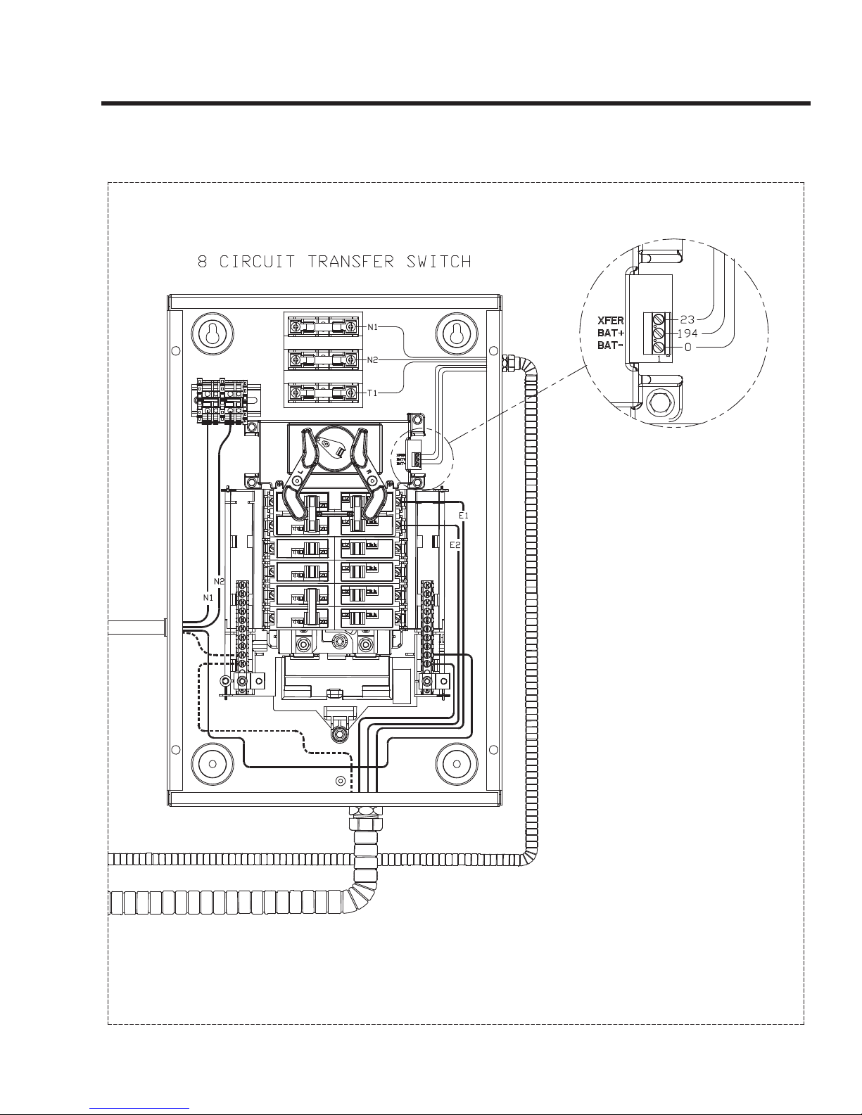
Section 3.1 – Description and Components ....................... 38
General ................................................................. 38
Enclosure ............................................................. 38
EZ Transfer Operator ............................................. 38
Fuse Holder .......................................................... 38
Page 1
Page 1
Page 4

Section 3.2 – Operational Analysis .................................... 39
Utility Voltage Present
Transfer to Standby
........................................... 39
............................................... 39
Transfer to Utility ................................................... 39
Section 3.3 – Troubleshooting Flowcharts ......................... 41
Introduction
.......................................................... 41
Problem 10 – In Automatic Mode,
No Transfer to Standby
......................................... 41
Problem 11 – In Automatic Mode, Generator
Starts When Loss of Utility Occurs, Generator
Shuts Down When Utility Returns But There is No
Retransfer To Utility Power OR Generator Transfers
to Standby During Exercise or in Manual Mode ...... 41
Problem 12 – Blown F1 or F2 Fuse ........................42
Problem 13 – Blown T1 Fuse
................................ 42
Problem 14 – Unit Starts and Transfer Occurs
When Utility Power is On
....................................... 42
Section 3.4 – Diagnostic Tests .......................................... 43
Introduction .......................................................... 43
Safety ................................................................... 43
Transfer Switch Troubleshooting ..........................43
Test 27 – Check Generator Voltage at
Transfer Switch ...................................... 43
Test 28 – Test Transfer Operator ............................43
Test 29 – Check 15B/194 Circuit .......................... 43
Test 30 – Check Wire 23 Circuit ............................ 44
Test 32 – Check Fuses F1 and F2 .......................... 44
Test 33 – Check N1 and N2 Wiring ........................ 45
Test 35 – Check Fuse F3 ...................................... 45
Test 36 – Check T1 Wiring .................................... 45
Test 38 – Check N1 and N2 Voltage ...................... 46
Test 39 – Check Utility Sense Voltage .................... 46
Test 40 – Check Utility Voltage at Transfer Switch .. 46
Test 41 – Check Utility Sensing Voltage
at the Controller ..................................... 46
PART 4 – Engine/DC Control ..............................................49
Section 4.1 – Description and Components ....................... 50
General ................................................................. 50
Terminal Strip / Interconnection Terminal ............... 50
Controller ............................................................. 50
Auto-Off-Manual Switch ........................................ 50
7.5 Amp Fuse ....................................................... 50
Alarms ................................................................. 52
Clear Alarms ......................................................... 52
Warnings .............................................................. 52
Section 4.3 – Operational Analysis .................................... 54
Utility Source Available .......................................... 54
Utility Failure and Engine Cranking ......................... 55
Utility Failure and Engine Running ..........................56
Section 4.4 – Troubleshooting Flowcharts ......................... 57
Problem 20 – Engine Will Not Crank When
Utility Power Source Fails
...................................... 57
Problem 21 – Engine Will Not Crank When
AUTO-OFF-MANUAL Switch is Set to “MANUAL”
... 57
Problem 22 – Engine Cranks but Won’t Start ......... 58
Problem 23 – Engine Starts Hard and
Runs Rough / Lacks Power / Backfires .................. 59
Problem 24 – Shutdown Alarm/Fault Occurred
Problem 25 – 7.5 Amp Fuse (F1) Blown
...... 60
................ 61
Problem 26 – Generator Will Not Exercise ............. 61
Problem 27 – No Battery Charge ........................... 61
Section 4.5 – Diagnostic Tests
Introduction
.......................................................... 62
.......................................... 62
Safety ................................................................... 62
Engine/DC Troubleshooting .................................. 62
Test 52 – Check Position Of
Auto-Off-Manual Switch ....................... 62
Test 53 – Try a Manual Start ................................ 63
Test 54 – Test Auto Operations .............................. 63
Test 55 – Check 7.5 Amp Fuse.............................. 63
Test 56 – Check Battery ........................................ 63
Test 57 – Check Wire 56 Voltage ........................... 65
Test 58 – Test Starter Contactor ............................ 65
Test 59 – Test Starter Motor .................................. 66
Test 60 – Check Fuel Supply and Pressure ............ 67
Test 61 – Check Circuit Board Wire 14 Output ....... 68
Test 62 – Check Fuel Solenoid .............................. 69
Test 63 – Check Choke Solenoid ........................... 69
Test 64 – Check for Ignition Spark ......................... 69
Test 65 – Check Spark Plugs ................................ 70
Test 66 – Check Engine / Cylinder Leak
Down Test / Compression Test ............... 71
Cylinder Leak Down Test ........................ 71
Check Compression ............................... 71
Test 67 – Check Ignition Coil ................................. 72
Test 68 – Check Oil Pressure Switch And Wire 86 . 72
Test 69 – Check High Oil Temperature Switch ........ 73
Test 70 – Check and Adjust Valves ........................ 74
Test 71 – Check Wire 18 Continuity ....................... 75
Test 72 – Test Exercise Function ........................... 75
Test 73 – Test Cranking and Running Circuits ........ 75
Test 74 – Test Run Circuit ..................................... 76
Test 75 – Test Crank Circuit .................................. 76
Test 76 – Check Battery Charger Supply Voltage.... 76
Test 77 – Check Battery Charger Output Voltage .... 77
Test 78 – Check Wire 0/15B.................................. 77
Test 79 – Check Shutdown Wire ........................... 77
Page 2
Page 5

PART 5 – Disassembly .......................................................81
Section 5.1 – Major Disassembly
Section 5.2 – Exploded Views
...................................... 82
........................................... 90
PART 6 – Electrical Data ..................................................101
Wiring Diagram ...............................................................102
Electrical Schematic
Electrical Formulas
.......................................................103
.........................................................104
Appendix A – Supplemental Worksheets..........................105
Appendix B – Index of Figures and Tables .......................109
Index of Figures
Index of Tables
.............................................................. 110
................................................................111
Page 3
Page 3
Page 6

Specifications
Caution: Specifications are for reference only, for actual installations always use the most recent version available online.
These specifications are subject to change without notice.
GENERATOR
Rated Voltage 240
Rated Maximum Load Current (Amps) at 240 Volts (LP)* 29.2
Main Circuit Breaker 30 Amp
Transfer Switch Load Center Circuits** 30A, 240V 1
30A, 240V 1
20A, 120V 3
15A, 120V 3
Phase 1
Number of Rotor Poles 2
Rated AC Frequency 60 Hz
Battery Requirement Group 26R, 12 Volts and 525 CCA Minimum
Weight (unit only in lbs.) 225
Enclosure Composite
Normal Operating Range: This unit is tested in accordance to UL 2200 standards with an operating temperature of -20 °F (-29 °C) to 122 °F. (50 °C). For areas
where temperatures fall below 32 °F (0 °C), a cold weather kit is highly recommended. When operated above 77º F (25º C) there may be a decrease in engine
power. (Please reference the engine specifications section).
These generators are rated in accordance with UL2200, Safety Standard for Stationary Engine Generator Assemblies; and CSA-C22.2 No. 100-04 Standard for
Motors and Generators.
* Natural Gas ratings will depend on specific fuel Btu content. Typical derates are between 10-20% off the LP gas rating.
** Circuits to be moved must be protected by same size breaker. For example, a 15 amp circuit in the main panel must be a 15 amp circuit in the transfer switch.
ENGINE
Type of Engine OHV-432
Number of Cylinders 1
Rated Horsepower @ 3,600 rpm* 14.8
Displacement 432cc
Cylinder Block Aluminum w/Cast Iron Sleeve
Valve Arrangement Overhead Valves
Ignition System Solid-state w/Magneto
Recommended Spark Plug RC12YC
Spark Plug Gap 0.76 mm (0.030 inch)
Compression Ratio 8.2:1
Starter 12 VDC
Oil Capacity Including Filter Approx. 1.1 Qts (1.0L)
Recommended Oil Filter Part # 0H9039
Recommended Air Filter Part # 0H6104
Operating RPM 3,600
* Engine power is subject to and limited by such factors as fuel Btu content, ambient temperature and altitude. Engine power decreases about 3.5 percent for each
1,000 feet above sea level; and also will decrease about 1 percent for each 6 C (10 F) above 16 C (60 F) ambient temperature.
Page 4
Page 7
Specifications
FUEL CONSUMPTION
Unit
6/7 kW 66 119 0.82/30 1.47/53
* Natural gas is in cubic f eet per hour . **LP is in gallons per hour/cubic feet per hour. Values given are approximate.
1/2 Load Full Load 1/2 Load Full Load
Natural Gas* LP Vapor**
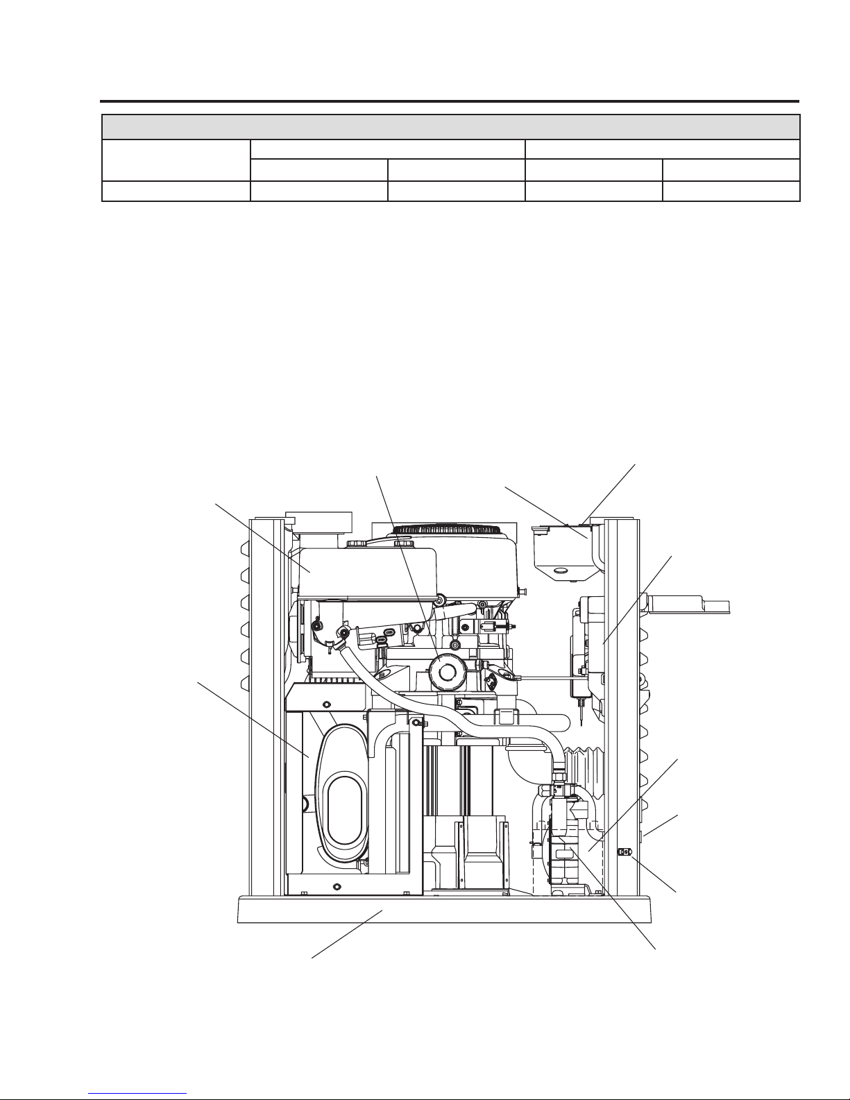
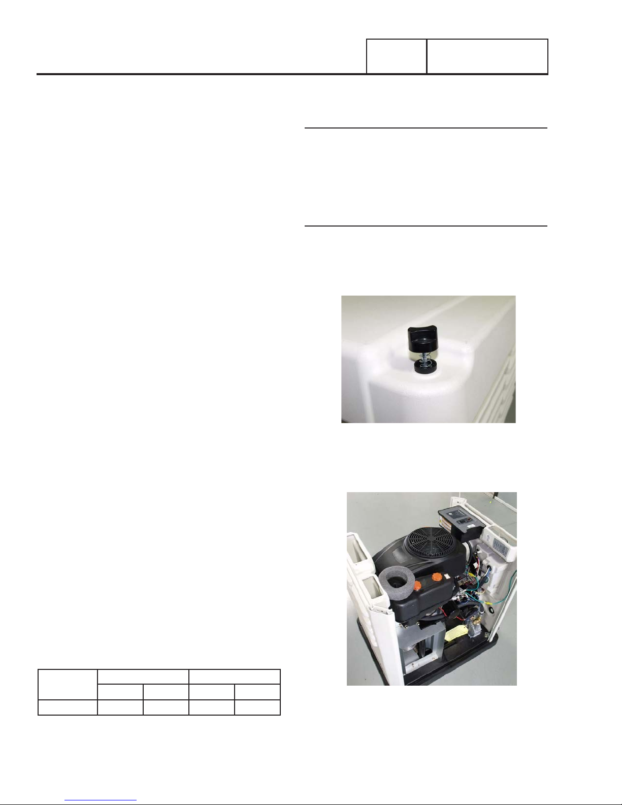
MAJOR FEATURES
Air Filter
Exhaust
Enclosure
Oil Filter
Data Label
(see sample)
Control Panel
Circuit Breaker
Battery
Fuel Inlet
Base
Ground Lug
Fuel Regulator
Page 5
Page 8
Specifications
Page 6
Page 9
Specifications
Page 7
Page 10

NOTES
Page 8
Page 11

PART 1
GENERAL INFORMATION
PART 1 – GENERAL INFORMATION ......................................9
Section 1.1 – Generator Basics
Introduction
Parts .................................................................... 10
Generator Identification ......................................... 10
Section 1.2 – Measuring Electricity
Meters
The VOM .............................................................. 11
Measuring AC Voltage ...........................................11
Measuring DC Voltage ...........................................11
Measuring AC Frequency ...................................... 11
Measuring Current ................................................ 12
Measuring Resistance ........................................... 12
Electrical Units ...................................................... 13
Ohm’s Law ........................................................... 13
Section 1.3 – Preparation Before Use ................................ 14
Introduction .......................................................... 14
Fuel Consumption ................................................. 14
Reconfigure the fuel system .................................. 14
Section 1.4 – Operating Instructions ................................. 16
Control Panel ........................................................ 16
User Interface ....................................................... 16
Automatic Operation ............................................. 16
Manual Operation.................................................. 16
.......................................................... 10
.................................................................. 11
......................................... 10
...................................11
Section 1.5 – Automatic Operating Parameters .................. 18
Introduction
Utility Failure
Cranking ............................................................... 18
Cranking conditions .............................................. 18
Load Transfer Parameters
Section 1.6 – General Maintenance
Introduction .......................................................... 20
Engine Oil ............................................................. 20
Engine Oil Recommendations ................................ 20
Air Filter ................................................................ 20
Spark Plugs .......................................................... 20
Visual Inspection .................................................. 20
Corrosion Protection ............................................. 20
Valve Clearance .................................................... 20
Battery ................................................................. 21
Section 1.7 – General Troubleshooting .............................. 22
Introduction .......................................................... 22
Recommended Tools ............................................ 22
Troubleshooting Reminders and Tips ..................... 22
Connectors ........................................................... 22
.......................................................... 18
......................................................... 18
..................................... 18
................................... 20
Page 9
Page 12
Section 1.1
Generator Basics
PART 1
GENERAL INFORMATION
INTRODUCTION
This diagnostic repair manual has been prepared especially for
familiarizing service personnel with the testing, troubleshooting
and repair of the vertical home standby systems. Every
effort has been expended to ensure that the information and
instructions in the manual are both accurate and current.
However, the manufacture reserves the right to change, alter
or otherwise improve the product at any time without prior
notification.
The manual has been divided into several PARTS. Each PART
has been divided into SUBSECTIONS and each subsection
consists of several sub headings.
It is not the manufacturer's intent to provide detailed disassembly
and reassembly of the vertical home standby. It is the
manufacturer's intent to (a) provide the service technician
with an understanding of how the various assemblies and
systems work, (b) assist the technician in finding the cause
of malfunctions, and (c) effect the expeditious repair of the
equipment.
PARTS
Part 1 – Provides the basic understanding of the generator as
well as operating instructions for commons tasks.
Part 2 – Provides the basics of the AC alternator design and the
AC troubleshooting portion of the manual.
Part 3 – Provides the troubleshooting and diagnostic testing
procedure for the 50 amp transfer switch with the EZ Transfer
Operator.
Part 4 – Provides the troubleshooting and diagnostic procedure
for the engine related problems and the controller.
Part 5 – Provides detailed step-by-step instructions for the
replacement of the rotor/stator and engine.
Part 6 – Illustrates all of the electrical and wiring diagrams for
the generator and transfer switch.
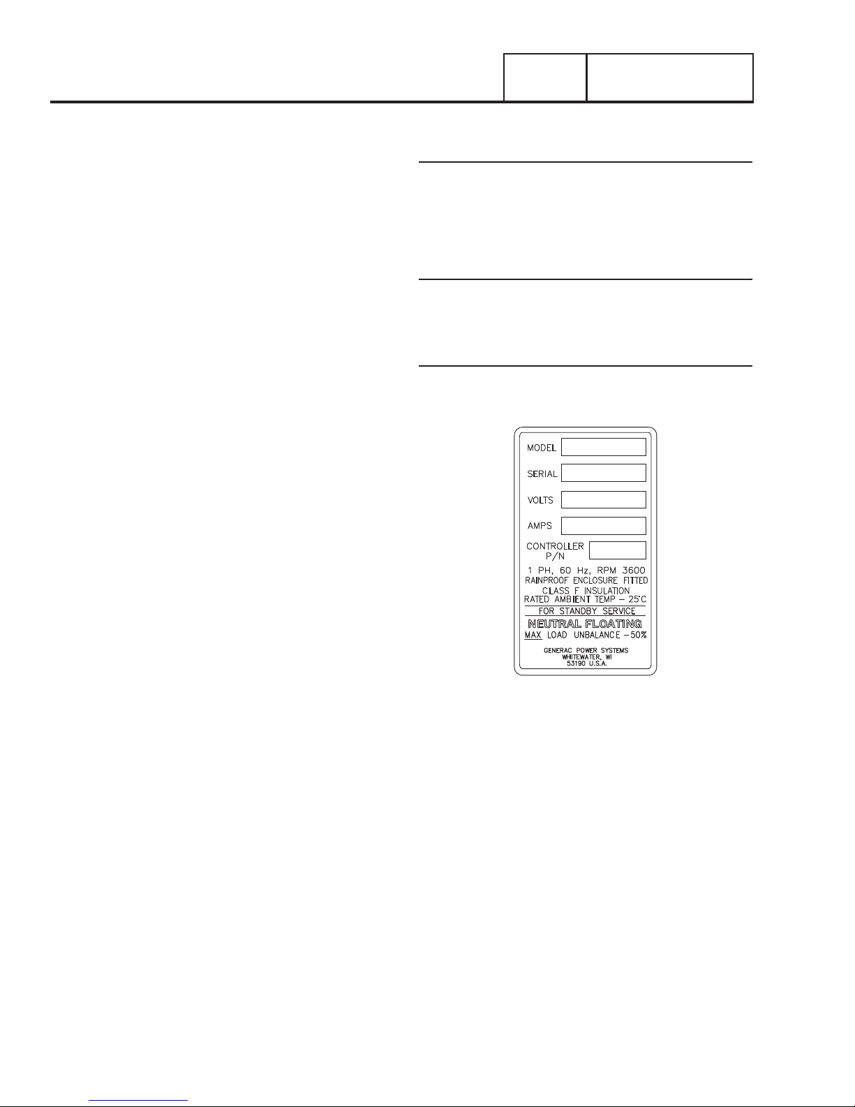
GENERATOR IDENTIFICATION
Data Plate
The data plate that is affixed to the generator contains
important information pertaining to the unit, including its model
number, serial number, amperage rating, and voltage rating.
The information from this data plate may be required when
requesting information, ordering parts from the factory.
Item Number
Many home standby generators manufactured are to the unique
specifications of the buyer. The model number identifies the
specific generator set and its unique design specifications.
Serial Number
Used for warranty tracking purposes.
Figure 1. Typical Data Plate
Page 10
Page 13
GENERAL INFORMATION
GENERAL INFORMATION
PART 1
PART 1
Section 1.2
Section 1.2
Installation Basics
Measuring Electricity
METERS
Devices used to measure electrical properties are called
meters. Meters are available that allow one to measure (a) AC
voltage, (b) DC voltage, (c) AC frequency, and (d) resistance In
ohms. The following apply:
•To measure AC voltage, use an AC voltmeter.
•To measure DC voltage, use a DC voltmeter.
•Use a frequency meter to measure AC frequency In “Her tz”
or “cycles per second”.
•Use an ohmmeter to read circuit resistance, in “ohms”.
THE VOM
A meter that will permit both voltage and resistance to be read
is the “Volt-Ohm-Milliammeter” or “VOM”.
Some VOMs are of the “analog” type (not shown). These
meters display the value being measured by physically
deflecting a needle across a graduated scale. The scale used
must be Interpreted by the user.
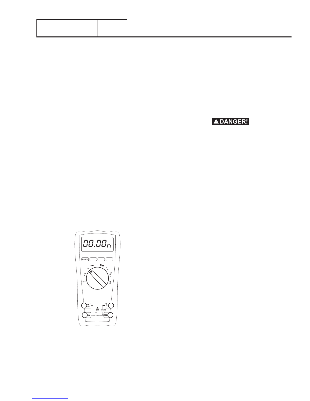
“Digital” VOM’s (Figure 2) are also available and are generally
very accurate. Digital meters display the measured values
directly by converting the values to numbers.
Note: Standard AC voltmeters react to the AVERAGE value
of alternating current. When working with AC, the effective
value is used. For that reason a different scale is used on
an AC voltmeter. The scale is marked with the effective or
“rms” value even though the meter actually reacts to the
average value. That is why the AC voltmeter will give an
Incorrect reading if used to measure direct current (DC).
MEASURING AC V OL T A GE
An accurate AC voltmeter or a VOM may be used to read the
generator’s AC output voltage. The following guidelines apply:
1. Always read the generator’s AC output voltage at the
unit’s rated operating speed and AC frequency.
2. The generator’s rated AC output voltage is 250 to 254
VAC and is not adjustable.
3. Only an AC voltmeter may be used to measure AC
voltage. DO NOT USE A DC VOLTMETER FOR THIS
PURPOSE.
Generators produce high and dangerous voltages.
Contact with high voltage terminals will result in
dangerous and possibly lethal electrical shock.
MEASURING DC VOL T A GE
A DC voltmeter or a VOM may be used to measure DC voltages.
Always observe the following rules:
1. Always observe correct DC polarity.
a. Some VOM’s may be equipped with a polarity switch.
b. On meters that do not have a polarity switch, DC
polarity must be reversed by reversing the test leads.
2. Before reading a DC voltage, always set the meter to a
higher voltage scale than the anticipated reading. If in
doubt, start at the highest scale and adjust the scale
downward until correct readings are obtained.
Figure 2. Digital VOM
3. The design of some meters is based on the “current flow”
theory while others are based on the “electron flow”
theory.
a. The “current flow” theory assumes that direct current
flows from the positive (+) to the negative (-).
b. The “electron flow” theory assumes that current flows
from negative (-) to positive (+).
Note: When testing generators, the “current flow” theory is
applied. That is, current is assumed to flow from positive
(+) to negative (-).
MEASURING AC FREQUENCY
The generator’s AC output frequency is proportional to Rotor
speed. Generators equipped with a 2-pole Rotor must operate
at 3600 rpm to supply a frequency of 60 Hertz. Units with
4-pole Rotors must run at 1800 rpm to deliver a 60 Hertz
output.
Page 11
Page 14

Section 1.2
Measuring Electricity
PART 1
GENERAL INFORMATION
MEASURING CURRENT
Clamp-On
To read the current flow, in AMPERES, a clamp-on ammeter
may be used. This type of meter indicates current flow
through a conductor by measuring the strength of the magnetic
field around that conductor. The meter consists essentially
of a current transformer with a split core and a rectifier type
instrument connected to the secondary. The primary of the
current transformer is the conductor through which the current
to be measured flows. The split core allows the Instrument
to be clamped around the conductor without disconnecting it.
Current flowing through a conductor may be measured safely
and easily. A line-splitter can be used to measure current in a
cord without separating the conductors.
In-Line
Alternatively, to read the current flow in AMPERES, an in-line
ammeter may be used. Most Digital Volt Ohm Meters (VOM)
will have the capability to measure amperes.
This usually requires the positive meter test lead to be connected
to the correct amperes plug, and the meter to be set to the
amperes position. Once the meter is properly set up to measure
amperes the circuit being measured must be physically broken.
The meter will be in-line or in series with the component being
measured.
In Figure 5 the control wire to a relay has been removed. The
meter is used to connect and supply voltage to the relay to
energize it and measure the amperes going to it.
1.00 A
BATTERY
+-
RELAY
Figure 3. Clamp-On Ammeter
Figure 4. A Line-Splitter
Note: If the physical size of the conductor or ammeter
capacity does not permit all lines to be measured simultaneously, measure current flow in each individual line.
Then, add the individual readings.
Figure 5. A VOM as an In-line Amp Meter
MEASURING RESISTANCE
The Volt-Ohm-Milliammeter may be used to measure the
resistance in a circuit. Resistance values can be very valuable
when testing coils or windings, such as the Stator and Rotor
windings, or checking a wire for an open or grounded condition.
When testing Stator windings, keep in mind that the resistance
of these windings is very low. Some meters are not capable of
reading such a low resistance and will simply read CONTINUITY.
If proper procedures are used, the following conditions can be
detected using a VOM:
•A “shor t-to-ground” condition in any Stator or Rotor
winding, or a short to ground on a specific control wire.
•Shorting together of any two parallel Stator windings.
•Shorting together of any two isolated Stator windings.
•An open condition in any Stator or Rotor winding, or an open
in a control wire.
Page 12
Page 15
GENERAL INFORMATION
PART 1
Section 1.2
Measuring Electricity
Component testing may require a specific resistance value
or a test for INFINITY or CONTINUITY. Infinity is an OPEN
condition between two electrical points, which would read as
no resistance, or OL (Open Line) on a VOM. Continuity is a
closed condition between two electrical points, which would
be indicated as very low resistance (000.000) or “ZERO” on
a VOM.
ELECTRICAL UNITS
Ampere
The rate of electron flow in a circuit is represented by the
AMPERE. The ampere is the number of electrons flowing past
a given point at a given time. One AMPERE is equal to just
slightly more than 6.241x10
With alternating current (AC), the electrons flow first in one
direction, then reverse and move in the opposite direction.
They will repeat this cycle at regular intervals. A wave diagram,
called a “sine wave” shows that current goes from zero to
maximum positive value, then reverses and goes from zero
to maximum negative value. Two reversals of current flow
is called a cycle. The number of cycles per second is called
frequency and is usually stated in “Hertz”.
Volt
The VOLT is the unit used to measure electrical PRESSURE,
or the difference in electrical potential that causes electrons to
flow. Very few electrons will flow when voltage is weak. More
electrons will flow as voltage becomes stronger. VOLTAGE
may be considered to be a state of unbalance and current flow
as an attempt to regain balance. One volt is the amount of
Electromotive Force (EMF) that will cause a current of 1 ampere
to flow through 1 ohm of resistance.
18
electrons per second.
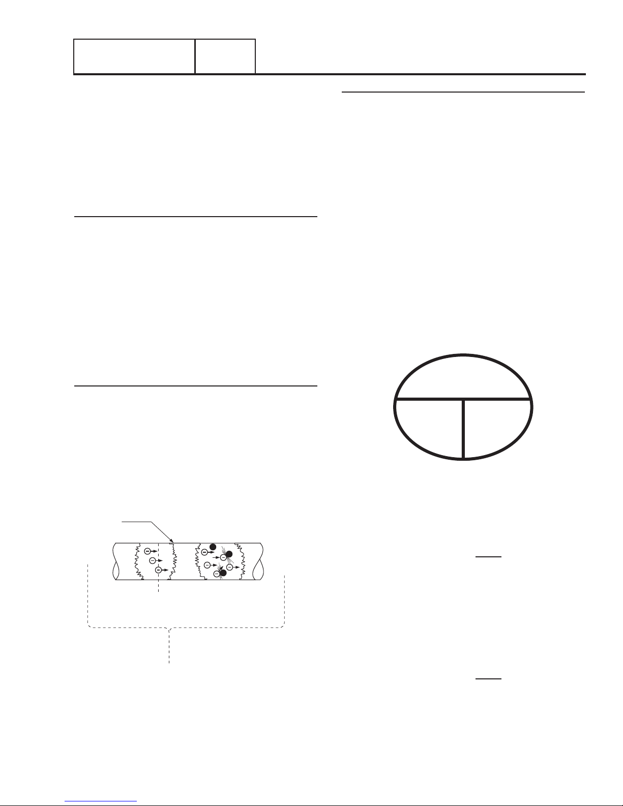
Ohm
The OHM is the unit of RESISTANCE. In every circuit there
is a natural resistance or opposition to the flow of electrons.
When an EMF is applied to a complete circuit, the electrons
are forced to flow in a single direction rather than their free or
orbiting pattern. The resistance of a conductor depends on
(a) its physical makeup, (b) its cross-sectional area, (c) its
length, and (d) its temperature. As the conductor’s temperature
increases, its resistance increases in direct proportion. One (1)
ohm of resistance will permit one (1) ampere of current to flow
when one (1) volt of EMF is applied.
OHM’S LAW
A definite and exact relationship exists between VOLTS, OHMS
and AMPERES. The value of one can be calculated when the
value of the other two are known. Ohm’s Law states that in
any circuit the current will increase when voltage increases but
resistance remains the same, and current will decrease when
resistance increases and voltage remains the same.
VOLTS
(E)
AMPS
(I)
OHMS
(R)
-
Conductor of a
Circuit
OHM - Unit measuring resistance
or opposition to flow
AMPERE - Unit measuring rate of
current flow (number of electrons
past a given point)
VOLT - Unit measuring force or
difference in potential
causing current flow
Figure 6. Electrical Units
+
Figure 7. Ohm’s Law
If AMPERES is unknown while VOLTS and OHMS are known,
use the following formula:
OHMS
If VOLTS is unknown while AMPERES and OHMS are known,
use the following formula:
If OHMS is unknown but VOLTS and AMPERES are known, use
the following:
AMPERES
AMPERES =
VOLTS = AMPERES x OHMS
OHMS
VOLTS
VOLTS
=
Page 13
Page 16
Section 1.3
Preparation Before Use
PART 1
GENERAL INFORMATION
INTRODUCTION
It is the responsibility of the installer to ensure that the Generator
installation was performed properly. A careful inspection
must be performed when the installation is complete. All
applicable codes, standards, and regulations pertaining to
such installations must be strictly complied with. In addition,
regulations established by the Occupational Safety and Health
Administration (OSHA) must be complied with as well.
Prior to initial startup of the unit, the installer must ensure that
the Generator has been properly prepared for use. This includes
the following:
•An adequate supply of the correct fuel must be available for
Generator operation.
•The engine must be properly serviced with the
recommended oil.
•With liquid propane (LP), use only the “vapor withdrawal”
system. This type of system uses the vapors formed above
the liquid fuel in the storage tank.
The engine has been fitted with a fuel carburetion system that
meets the specification of the 1997 California Air Resources
Board for tamper-proof dual fuel systems. The unit will run
on natural gas or LP, but it has been factory set and tested to
run on natural gas. When the change from natural gas to LP is
needed, the fuel system needs to be re-configured.
Recommended fuels should have a British Thermal Unit (BTU)
content of at least 1,000 BTU’s per cubic feet for natural gas; or
at least 2,520 BTU’s per cubic feet for LP. Ask the fuel supplier
for the BTU content of the fuel.
Recommended fuel pressures for natural gas and liquid
propane vapor (LPV) are as follows:
Note: All pipe sizing, construction and layout must comply
with NFPA 54 for natural gas applications and NFPA 58 for
liquid propane applications. After installation, verify that the
fuel pressure NEVER drops below five (5) inches water column for natural gas or ten (10) inches water column for LPV.
Prior to installation of the Generator, the installer should consult
local fuel suppliers or the fire marshal to check codes and
regulations for proper installation. Local codes will mandate
correct routing of gaseous fuel line piping around gardens,
shrubs and other landscaping to prevent any damage.
Special considerations should be given when installing the unit
where local conditions include flooding, tornados, hurricanes,
earthquakes and unstable ground for the flexibility and strength
of piping and their connections.
Use an approved pipe sealant or joint compound on all threaded
fittings.
Verify that gas meter is capable of providing enough fuel flow
to include household appliances.
Btu Flow Requirements - Natural Gas
BTU flow required for each unit based on 1000 BTU per cubic
foot.
•6kW — 119,000 BTU/Hour (Natural Gas)
RECONFIGURE THE FUEL SYSTEM
Procedure
1. Remove the generator enclosure roof by turning the four
quarter turn latches on the roof top. Push down slightly
on the latch then turn 90 degrees to release. The latch
should pop up as shown.
Figure 8.
2. Remove the two side panels of the enclosure by lifting the
panels straight up until they are clear.
FUEL CONSUMPTION
Unit
6/7 kW 66 119 0.82/30 1.47/53
* Natural gas is in cubic f eet per hour .
**LP is in gallons per hour/cubic feet per hour.
Values given are approximate.
Page 14
Natural Gas* LP Vapor**
1/2 Load Full Load 1/2 Load Full Load
Figure 9.
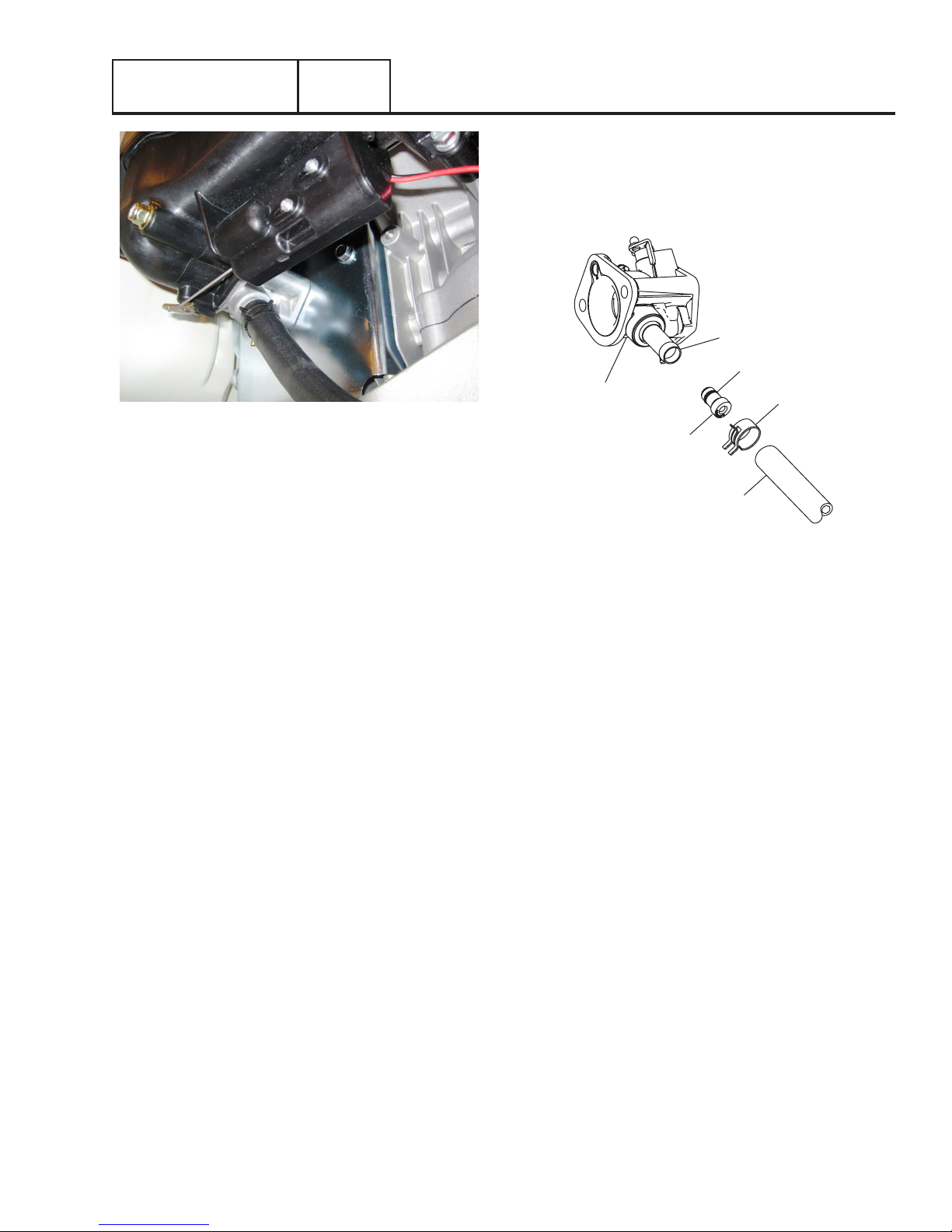
3. Carefully place the roof and side panels to one side.
4. Locate the fuel throttle assembly mounted to the engine
intake.
Page 17
GENERAL INFORMATION
PART 1
Figure 10.
5. To change the fuel selection, remove the hose clamp and
hose from the throttle assembly.
6. Remove the Natural Gas (Larger ID) fuel jet from the fuel
inlet.
Section 1.3
Preparation Before Use
9. Insert the Propane fuel jet into the end of the fuel inlet.
10. Reinstall the hose and clamp onto the fuel inlet and
secure.
11. Verify the hose has not been kinked in any way.
Fuel Inlet
O-Ring (installed)
Throttle
Assembly
Fuel Jet
Regulator
Hose
Hose Clamp
7. Obtain the fuel jet for Propane (Smaller ID that has been
supplied loose with the owners manual).
8. Verify that the O-ring, supplied loose with the owners
manual is installed, into the groove of the fuel jet.
Figure 11.
12. The generator is now ready to run on LP Vapor fuel.
Page 15
Page 18

Section 1.4
Operating Instructions
PART 1
GENERAL INFORMATION
CONTROL PANEL
WARNING! With the switch set to AUTO, the engine
may crank and start at any time without warning. Such
automatic starting occurs when Utility power source
voltage drops below a preset level or during the normal
exercise cycle. To prevent possible injury that might be
caused by such sudden starts, always set the switch to
the OFF position and remove the fuse before working on
or around the Generator or transfer switch. Then, place
a “DO NOT OPERATE” tag on the Generator panel and
on the transfer switch.
AUTO-OFF-MANUAL
AUTO – Selecting this switch activates fully automatic system
operation. It also allows the unit to automatically start and
exercise the engine every seven days at the time chosen by
the user.
OFF – This switch position shuts down the engine. This
position also prevents automatic operation.
MANUAL – Setting the switch to the MANUAL position will
crank and start the engine. Transfer to standby power will not
occur unless there is a failure of Utility.
7.5 Amp Fuse
This fuse protects the controller as wells as the DC components
against overload. If the fuse element has melted open due to an
overload, engine cranking and or running will not be possible.
Should a fuse replacement become necessary, use only an
identical 7.5 amp replacement fuse.
USER INTERFACE
The generator is equipped with an internal exercise timer. Once
set, the Generator will start and exercise every seven days, on
the day of the week and the time of day specified. During this
exercise period, the unit runs for approximately 12 minutes and
then shuts down. Transfer of loads to the Generator output
does not occur during the exercise cycle unless Utility is lost.
Refer to “Setting the exercise time” in Section 1.4.
Note: The exercise will only work with the AUTO-OFFMANUAL switch in the AUTO position.
To select automatic operation
The following procedure applies only to those installations
which utilize an air-cooled generator in conjunction with a
transfer switch. Residential transfer switches do not have
intelligent circuits of their own. Printed circuit board logic in
the controller controls the automatic operation of the transfer
switch and the generator.
To select automatic operation when a transfer switch is installed
along with a home standby generator, the procedure is as
follows.
1. Ensure that the transfer mechanism in the transfer switch
is in the “Utility” position. If needed, turn OFF or OPEN
the Utility source Main Line Circuit Breaker and manually
transfer the breaker to the “Utility” position.
2. CLOSE or turn ON the Utility source Main Line Circuit
Breaker and ensure Utility voltage is available to the
UTILITY terminals N1 and N2.
3. Actuate the Generator main line circuit breaker (MLCB) to
its “Closed” position.
4. Set the Generators AUTO-OFF-MANUAL switch to the
AUTO position.
Following the procedure of Steps 1 through 4, a dropout of
Utility voltage below a preset level will result in automatic
Generator cranking and start-up. Following startup, the transfer
switch will actuate to the “Standby” position.
MANUAL OPERATION
Transfer to “Standby” and Manual Startup
To transfer electrical loads to the Generator and to start the
generator manually, the procedure is as follows:
1. On the generator, set the AUTO-OFF-MANUAL switch to
the OFF position.
2. On the generator, set the main line circuit breaker (MLCB)
to the “Open” position.
3. Locate a means of Utility disconnect and set it to the OFF
position.
4. Manually actuate the breaker to the “Standby” position in
the transfer switch.
AUTOMATIC OPERATION
CAUTION! The Generators Voltage and Frequency must
be verified with the Generator Main Line Circuit Breaker
(MLCB) OFF or OPEN Prior to selecting Automatic or
Manual operation!
Page 16
5. On the generator, set the AUTO-OFF-MANUAL switch to
the MANUAL position.
WARNING! Engine will crank and start!
6. Let the engine warm up and stabilize for a minute or two
at no-load. Set the generators MLCB to the “Closed”
position. Generator voltage should now be available to
the transferred electrical loads.
Page 19

GENERAL INFORMATION
Retransfer Back to “Utility” and Manual Shutdown
To shutdown the generator and retransfer electrical loads back
to the “Utility” position, the procedure is as follows:
1. Set the generators MLCB to its OPEN position.
2. Allow the generator to run at no-load for several minutes
to cool down.
3. Set the generators AUTO-OFF-MANUAL switch to the OFF
position.
4. Locate a means of Utility disconnect and set it to the OFF
position.
5. Manually actuate the breaker in the transfer switch to the
“Utility” position.
6. Restore Utility voltage to the transfer switch, by the means
that was utilized in Step 4.
7. Set the generator’s AUTO-OFF-MANUAL switch to the
AUTO position.
With the generator in AUTO, a dropout in Utility voltage below
a preset level will result in automatic generator cranking and
start-up. Following startup, the transfer switch will actuate to
the “Standby” position.
PART 1
Section 1.4
Operating Instructions
Page 17
Page 20

Section 1.5
Automatic Operating Parameters
PART 1
GENERAL INFORMATION
INTRODUCTION
When the generator is installed in conjunction with a transfer
switch, either manual or automatic operation is possible.
UTILITY FAILURE
Initial Conditions
The generator is in AUTO, ready to run, and the transfer switch
is running on Utility. When Utility fails (below 65% of nominal),
a 10 second line interrupt delay time is star ted. If the Utility is
still not present when the timer expires, the engine will crank
and start. Once started a five (5) second engine warm-up timer
will start.
When the warm-up timer expires the controller will transfer load
to the generator. If Utility voltage is restored (above 75% of
nominal) at any time between the initiation of the engine start
and when the generator is ready to accept load, (five second
warm-up time has not elapsed), the controller will complete the
start cycle and run the generator through its normal cool down
cycle; however the switch will remain in the “Utility” position.
CRANKING
The controller will cyclic crank the engine 5 times as follows:
16 second crank, 7 second rest, 16 second crank, 7 second
rest, followed by 3 additional cycles of 7 second crank followed
by 7 second rests.
Failure To Start
Failure to start is defined as any of the following occurrences
during cranking.
1. Not reaching starter dropout within the specified crank
cycle.
Note: Starter dropout is defined as 4 cycles at 1,000 RPM
2. Reaching starter dropout, but not reaching 2200 rpm
within 15 seconds. After which the controller will go into
a rest cycle of 7 seconds, the continue the rest of the
crank cycle.
Note: During a rest cycle the start and fuel outputs are deenergized and the magneto output is shorted to ground.
5. Once the controller sees an RPM signal it will energize the
fuel solenoid and continue the crank sequence. The fuel
solenoid does not activate earlier because if the engine
does not crank, this would potentially fill the engine/
exhaust up with unspent fuel. It takes at least 3 seconds
to detect cranking on the engine with a magneto RPM
measurement. This would result in 3 seconds of fuel
being delivered, increasing the chances of a backfire.
6. The starter motor will disengage when speed reaches
starter dropout.
7. If the generator does not reach 2200 rpm within 15
seconds, re-crank cycle will occur.
8. If the engine stops turning between starter dropout and
2200 RPM the controller will go into a rest cycle of 7
seconds and re-crank ( if additional crank cycles exist.)
9. Once started the generator will wait for a hold off
period before starting to monitor oil pressure and oil
temperature. Refer to Section 4.2 “Engine Protective
Devices”
10. During a MANUAL crank attempt, if the AUTO-OFFMANUAL switch is set from MANUAL to OFF, the crank
attempt will abort.
11. During automatic crank attempt, if the Utility returns, the
crank cycle does NOT abort, but continues until complete.
Once the engine starts, it will run for one minute then
shutdown.
LOAD TRANSFER PARAMETERS
The transfer of load when the generator is running is dependent
upon the operating mode as follows:
Manual
•No transfer to Standby when Utility is present
•Transfer to Standby will occur if Utility fails (below 65% of
nominal) for 10 consecutive seconds.
•Transfer back to Utility when Utility returns for 15 consecu-
tive seconds. The engine will continue to run until removed
from the Manual mode.
CRANKING CONDITIONS
The following notes apply during the crank cycle
1. Starter motor will not engage within 5 seconds of the
engine shutting down.
2. The fuel output will not be energized with the starter
3. The starter and magneto outputs will be energized
together.
4. Once the star ter energizes, the controller will begin
looking for engine rotation. If it does not see an RPM
signal within 3 seconds it will shut down and latch out on
“RPM Sensor loss”
Page 18
Auto
•Transfer to standby will occur if Utility fails below (65% of
nominal) for 10 consecutive seconds.
•A five second engine warm-up timer will initialize
•Transfer back to the “Utility” position if Utility subsequently
returns
•Transfer to the “Standby” position if Utility is still not present.
•Transfer back to Utility once Utility returns (above 75% of
nominal) for 15 seconds.
•Transfer back to Utility, if present, if the generator is shutdown for any reason ( such as the switch turned to the OFF
position or a shutdown alarm.
Page 21

GENERAL INFORMATION
Exercise
•Exercise will not function if the generator is already running
in either AUTO or MANUAL mode.
•During exercise, the controller will only transfer if Utility fails
during exercise for 10 seconds, and will follow the steps
outline above for AUTO operation.
Utility Restored
The generator is running, switch is in the “Standby” position,
running in Utility failure. When the Utility returns (above 75%
of nominal), a 15 second return to Utility timer will start. At
the completion of this timer, if the Utility supply is still present
and acceptable, the controller will transfer the load back to
the Utility and run the engine through a one minute cool down
period and then shutdown. If Utility fails for three seconds
during this cool down period, the controller will transfer load
back to the generator and continue to run while monitoring for
Utility to return.
PART 1
Section 1.5
Automatic Operating Parameters
Page 19
Page 22
Section 1.6
General Maintenance
PART 1
GENERAL INFORMATION
INTRODUCTION
Performing proper maintenance on a Generator will ensure
proper function during a Utility failure. Once a Generator has
failed, it is already too late. Ensuring the proper oil changes and
inspections have been completed at the specified times will
help keep the Generator reliable.
ENGINE OIL
Modern oils play vital functions in protecting the engine.
Lubricating oil acts to reduce friction and wear, cool engine
parts, seal combustion chambers, clean engine components,
and inhibit corrosion. See Table 1 “Service Schedule” for
specific inspection items and interval
ENGINE OIL RECOMMENDATIONS
All oil should meet minimum American Petroleum Institute (API)
Service Class SJ, SL or better. Do not use special additives.
Select the oil’s viscosity grade according to the expected
operating temperature.
SAE 30 Above 32º F
10W-30 Between 40ºF and -10ºF
Synthetic 5W-30 10ºF and below
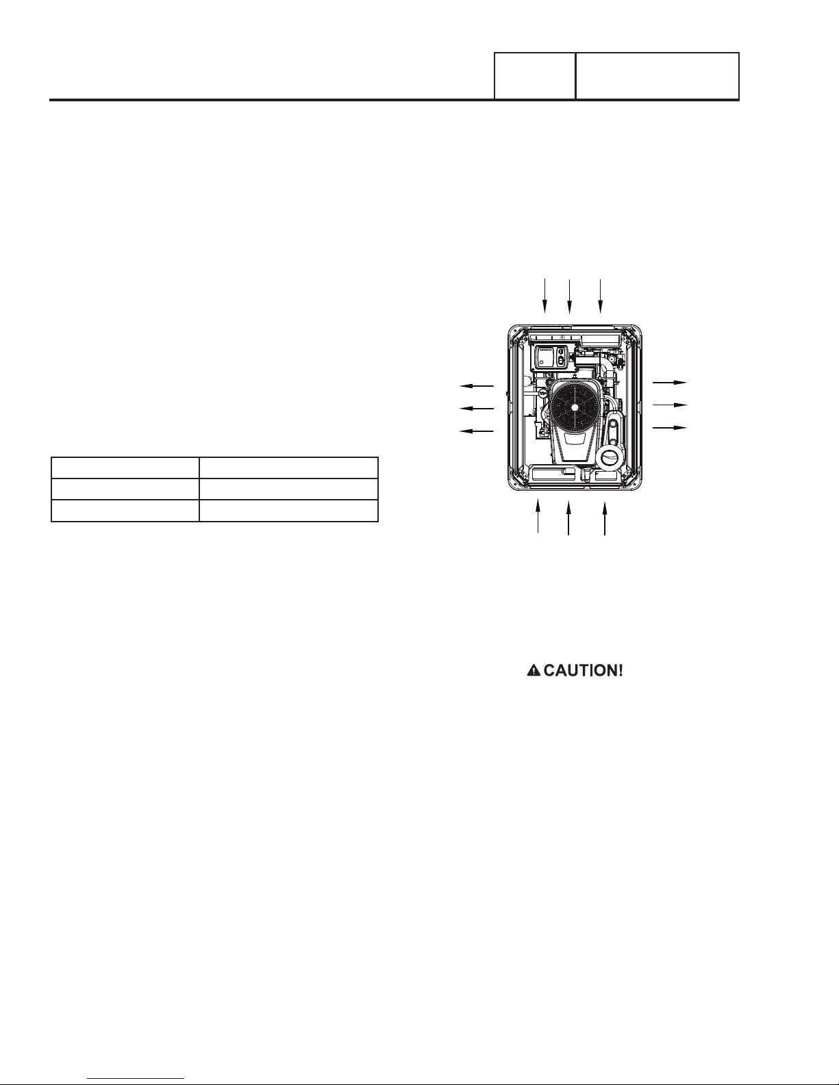
VISUAL INSPECTION
During all service intervals, a proper visual inspection must be
conducted to ensure proper function, airflow, and to prevent
fire hazards.
Air inlet and outlet openings in the Generator compartment
must be open and unobstructed for continued proper operation.
This includes such obstructions as high grass, weeds, brush,
leaves, and snow.
AIR INTAKE
AIR OUTLET
AIR OUTLET
AIR FILTER
Air is necessary for successful combustion in the engine. Clean
air (almost 100% pure) is critical to engine survival and vital to
its performance. There are operational signs when an air filter
has become completely plugged. The engine begins to lose
power, and fuel consumption increases. Black smoke may blow
from the exhaust. Continued operation with a plugged air filter
may cause severe damage to the engine.
SPARK PLUGS
Good spark is essential to properly maintaining the engine.
Although replacement may not be required, inspection of the
plugs during routine maintenance is critical. Always verify
that spark plugs are gapped according to the specifications.
Improperly gaped spark plugs will effect the operation of the
engine.
See Test 65 for diagnosing spark plug related problems.
See “Specifications” for specific spark plug gaps.
AIR INTAKE
Figure 12. Cooling Vent Locations
CORROSION PROTECTION
Spray engine linkages with a light oil such as WD-40.
CAUTION! Do not spray flammable oils on a hot or
running engine.
VALVE CLEARANCE
Proper valve clearance is vital to ensuring longevity of the
engine. After the first 6 months of operation, check the engine
valve clearance and adjust as necessary. Checking of the
engine valve clearance thereafter periodically will increase
reliability of the Generator. Refer to Test 70 for Specification and
adjustment procedure.
Some symptoms of an engine with valves in need of adjustment
are:
•Hard star ting
•Smoke out of the exhaust
•Rough running
•Lack of horse power
Page 20
Page 23

GENERAL INFORMATION
PART 1
General Maintenance
Section 1.6
BATTERY
Performing proper battery maintenance at the required intervals
will allow for proper starting of the Generator during a power
outage. Some common things to look for and check during
maintenance are:
•Inspect the battery posts and cables for tightness and
corrosion. Tighten and clean as necessary.
•Check the battery fluid level of unsealed batteries and, if necessary, fill with Distilled Water only. Do not use tap water in
batteries.
•Have the state of charge and conditions checked. This should
be done with an automotive-type battery hydrometer.
Note: See Test 56 for further testing the state of a battery.
Table 1. Service Schedule
SYSTEM/COMPONENT PROCEDURE FREQUENCY
X = Action
R = Replace as Necessary
Inspect Change Clean
* = Notify Dealer if Repair is
Needed.
FUEL
Fuel lines and connections*
X M
LUBRICATION
Oil level
Oil
Oil filter
X M or 24 hours of
X 1Y or 100 hours
X 1Y or 100 hours
COOLING
Enclosure louvers
X X W
BATTERY
Remove corrosion, ensure
dryness
Clean and tighten battery
terminals
Check charge state
Electrolyte level
X X M
X X M
X R EVERY 6 M
X R EVERY 6 M
ENGINE AND MOUNTING
Air cleaner
Spark plug
X R 1Y or 200 hours
X R 1Y or 200 hours
GENERAL CONDITION
Vibration, Noise, Leakage, Temperature*
X M
COMPLETE TUNE-UP* TO BE COMPLETED BY A DEALER 1Y or 200 hours
* Contact the nearest dealer for assistance if necessary.
** Change oil and filter after first eight (8) hours of operation and then every 100 hours thereafter, or 1 year, whichever occurs first.
Change sooner when operating under a heavy load or in a dusty or dirty environment or in high ambient temperatures.
W = Weekly
M = Monthly
Y = Yearly
continuous operation.
of operation.**
of operation.**
Page 21
Page 24

Section 1.7
General Troubleshooting
PART 1
GENERAL INFORMATION
INTRODUCTION
This section familiarizes the service technician with the
manufacturer recommended procedures for the testing and
evaluation of various problems that can occur on the standby
generators. It is highly recommended that you read these
introductory tips before you attempt to troubleshoot any of the
three main generator components: AC Generator, Engine, or
the Transfer Switch. The Troubleshooting Flow Charts provide
the simplest, quickest, systematic means to troubleshoot the
typical problems that might occur during the lifetime of the unit.
If you use the flow charts and perform the indicated tests, you
will be able to identify the faulty component, which can then be
repaired or replaced as necessary.
The test procedures in each section do require a basic
knowledge of electricity and electrical safety, hand tool skills,
and use of Volt-Ohm-Meters.
RECOMMENDED TOOLS
In addition to the normal hand tools required, some test
procedures may require the use of specialized test equipment.
At a minimum you must have a meter that measures AC
voltage and frequency, and DC voltage and current (digital
multi meters (DMM) are recommended); standard meter test
leads, a set of piercing probe leads , and a set of pin probe
leads for the connector pins. The manufacturer carries a set
of acceptable piercing probes (PN 0G7172), or other suppliers
piercing probes may be used. Fluke provides a high quality
piercing probe, PN AC89, which is highly recommended. The
manufacturer also carries a set of flexible pin leads for use with
the connector plugs (PN 0J09460SRV).
Recommended Tools Check List
p General Mechanics Tool Box
p A Meter Capable of Measuring Frequency (Hz), AC & DC
volts, DC amps, and Ohms
p A Clamp-on Ammeter
A 1/4” & 3/8” Metric & SAE Socket Set
p
p Allen Wrenches (Metric & SAE)
p Manometer
p Spark Tester
p Compression Gauge
p Oil Pressure Gauge
p Leak Down Tester
TROUBLESHOOTING REMINDERS AND TIPS
The most important step in troubleshooting is identifying the
actual problem.
The next step is to determine the applicable flow chart to use
to help diagnose the problem. Use the flow chart index for the
part of the generator you are working with. If it is problem with
voltage, use Part 2 – AC Generators; for engine problems use
Part 4 – Engine/DC Control; for a problem with the transfer
switch, use Part 3 – Transfer Switch. The index for each will
help you clarify the problem and the flow chart to use. In each
flow chart start at the top and use the test indicated to verify
whether a component or control item is working properly or not.
At the end of each test follow the “good” or “bad” arrows and
perform the next test.
It is always good practice to continue to ask questions during
the troubleshooting process. When evaluating a problem, these
questions may help identify the problem quicker.
•What is it doing? (low voltage; not cranking; not transferring;
etc)
•What should it do? (run and start; transfer; shutdown; etc)
•Does the same thing happen each time?
•When is it happening?
•What could or would cause this?
•What type of test will either prove or disprove the cause of
the fault?
Figure 13. Test Probes
For engine troubleshooting you will need a good manometer
which measures low pressure in Inches of Water Column (IN
WC or IN H20). An ignition spark tester is also a handy tool to
have when working with air-cooled engines.
Testing and troubleshooting methods covered in each section
are not exhaustive. No attempt has been made to discuss,
evaluate and advise the home standby service trade of all
conceivable ways in which service and trouble diagnosis must
be performed. Accordingly, anyone who uses a test method
not recommended herein must first satisfy himself that the
procedure or method he has selected will jeopardize neither
his nor the products safety, and will not cause damage to any
connectors or components.
Page 22
CONNECTORS
A number of the tests require the use of a volt-meter and a set
of wire piercing probes. When using the piercing probes make
sure you use some liquid tape or silicon to coat the insulation
where you pierced it; this will keep moisture out and prevent
long term corrosion.
It is very easy to damage the female pins in the connectors
on the control panel and the C1 connector (Molex connector)
which goes to the alternator can.
DO NOT ATTEMPT TO PUSH PROBE TIPS INTO THE FEMALE
PINS OF THE MOLEX CONNECTORS; doing so will damage the
female pin which will create another problem. Use the piercing
probes on the correct wire to check for the appropriate voltages
; or use the flexible pin leads, available from the manufacturer
(PN 0J09460SRV) to work with the connector plugs.
Page 25

PART 2
AC GENERATORS
PART 2 – AC Generators ....................................................23
Section 2.1 – Description and Components
Introduction
Engine-Generator Drive System ............................. 24
Alternator Assembly ............................................. 24
Brush Holder and Brushes
Other AC Generator Components
Section 2.2 – Operational Analysis .................................... 26
Startup ................................................................. 26
On-Speed Operation .............................................. 26
Field Excitation ...................................................... 26
AC Power Winding Output ..................................... 26
Section 2.3 – Troubleshooting Flowcharts ......................... 27
Introduction .......................................................... 27
Problem 1 – Generator Produces Zero Voltage
or Residual Voltage ............................................... 27
Problem 2 – Generator Produces
Low Voltage at No-Load ........................................28
Problem 3 – Generator Produces
High Voltage at No-Load .......................................29
Problem 4 - Voltage and Frequency
Drop Excessively When Loads Are Applied ............ 29
.......................................................... 24
.................................... 24
....................... 24
.......................... 25
Section 2.4 – Diagnostic Tests .......................................... 30
Introduction
Safety ................................................................... 30
AC Troubleshooting............................................... 30
Test 1 – Check Main Circuit Breaker ...................... 30
Test 4 – Fixed Excitation /Rotor Amp Draw Test ..... 30
Test 6 – Resistance Check of Rotor Circuit ............ 32
Test 7 – Check Brushes and Slip Rings
Test 9 – Test the Stator ......................................... 33
Test 10 – Test Rotor Assembly .............................. 34
Test 11 – Check AC Output Voltage ....................... 34
Test 12 – Check AC Output Frequency ................... 34
Test 13 – Adjust Engine Governor ......................... 35
Test 14 – Adjust Voltage Regulator ....................... 35
Test 15 – Check for Overload Condition ................. 36
Test 16 – Check Voltage and
Frequency Under Load ........................... 36
.......................................................... 30
................. 32
Page 23
Page 26
Section 2.1
SLIP RINGS
BEARING
Description and Components
INTRODUCTION
The alternator contained within the generator is a revolving field
(rotor) type with a stationary armature (stator), and excitation
to the field provided through brushes and slip rings (direct
excitation). The generator may be used to supply electrical
power for the operation of the 120 and/or 240 VAC, 1-phase,
60 Hz, AC loads.
ENGINE-GENERATOR DRIVE SYSTEM
The air-cooled engine is directly coupled to the rotor internally.
Both the engine and the rotor operate at 3600 rpm to provide a
60 HZ AC output.
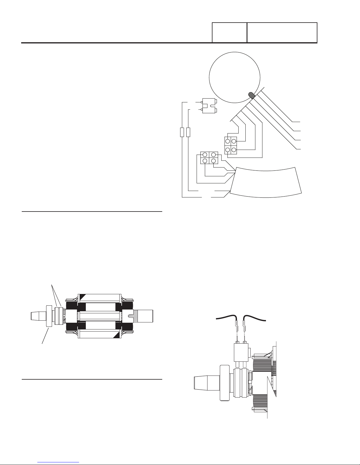
ALTERNATOR ASSEMBLY
The standard alternator consists of three basic components;
a rotor, stator, and brush assembly. The rotor assembly
provides the magnetic field which will induce a voltage into the
stator assembly. The brush assembly provides the electrical
connection to the rotor, which allows for excitation voltage and
current to create the needed magnetic field.
PART 2
STATOR
BA
RED
+
C1
RED(+)
WHT
BLK
IC
IC
AC GENERATORS
WHT
WHT
BLK
BLU
AVR
Rotor
Operating the 2-pole rotor at 3600 rpm will supply 60 HZ AC.
The term “2-pole” means the rotor has a single north and a
single south magnetic pole. Held in place with a single through
bolt, the tapered rotor shaft mounts to the tapered crankshaft
of the engine. As the rotor rotates its lines of magnetic flux cut
across the stator windings and induce a voltage into the stator
windings. The rotor shaft has a positive and negative slip ring,
with the positive slip ring nearest the lower bearing carrier. The
bearing is pressed onto the end of the rotor shaft.
Figure 14. Rotor
Stator
The stator houses a dual power winding and an excitation
winding. Coming from the stator there are eight stator leads as
shown in Figure 15.
An adapter molded into the engine block and a rear-bearing
carrier support the stator can. Four stator bolts connect the
rear bearing carrier and the stator can to the engine.
Figure 15. Stator Leads
BRUSH HOLDER AND BRUSHES
Attached to the lower bearing carrier, the brush holder and
brushes allow for electrical connection to the rotor. Positive
and negative brushes are retained in the brush holder, with the
positive brush riding on the slip ring nearest the rotor bearing.
The Red wire connects to the positive brush and the Black
Wire to the negative brush. The rotor windings receive rectified
and regulated field excitation voltage (DC) through the Red and
Black Wires. The current flow creates a magnetic field around
the rotor having a flux concentration that is proportional to the
amount of current flow on the Red and Black Wires.
RED
+
-
Figure 16. Brush Holder and Brushes
BLACK
Page 24
Page 27
AC GENERATORS
PART 2
OTHER AC GENERATOR COMPONENTS
Located within the generator control panel enclosure are the
voltage regulator and the main line circuit breaker.
Voltage Regulator
Unregulated AC output from the stator excitation winding is
delivered to the regulator’s DPE circuit through the two Blue
wires and C1-1 and C1-2. The voltage regulator rectifies
that voltage and, based on stator AC power winding sensing,
regulates it. The rectified and regulated field excitation current is
then delivered to the rotor windings from the positive (+) Red
Wire and negative (-) Black Wire (originates as White Wire from
regulator and changes to Black at the C1 connector). Stator AC
power winding “sensing” is delivered to the regulator through
the Green and White Wires.
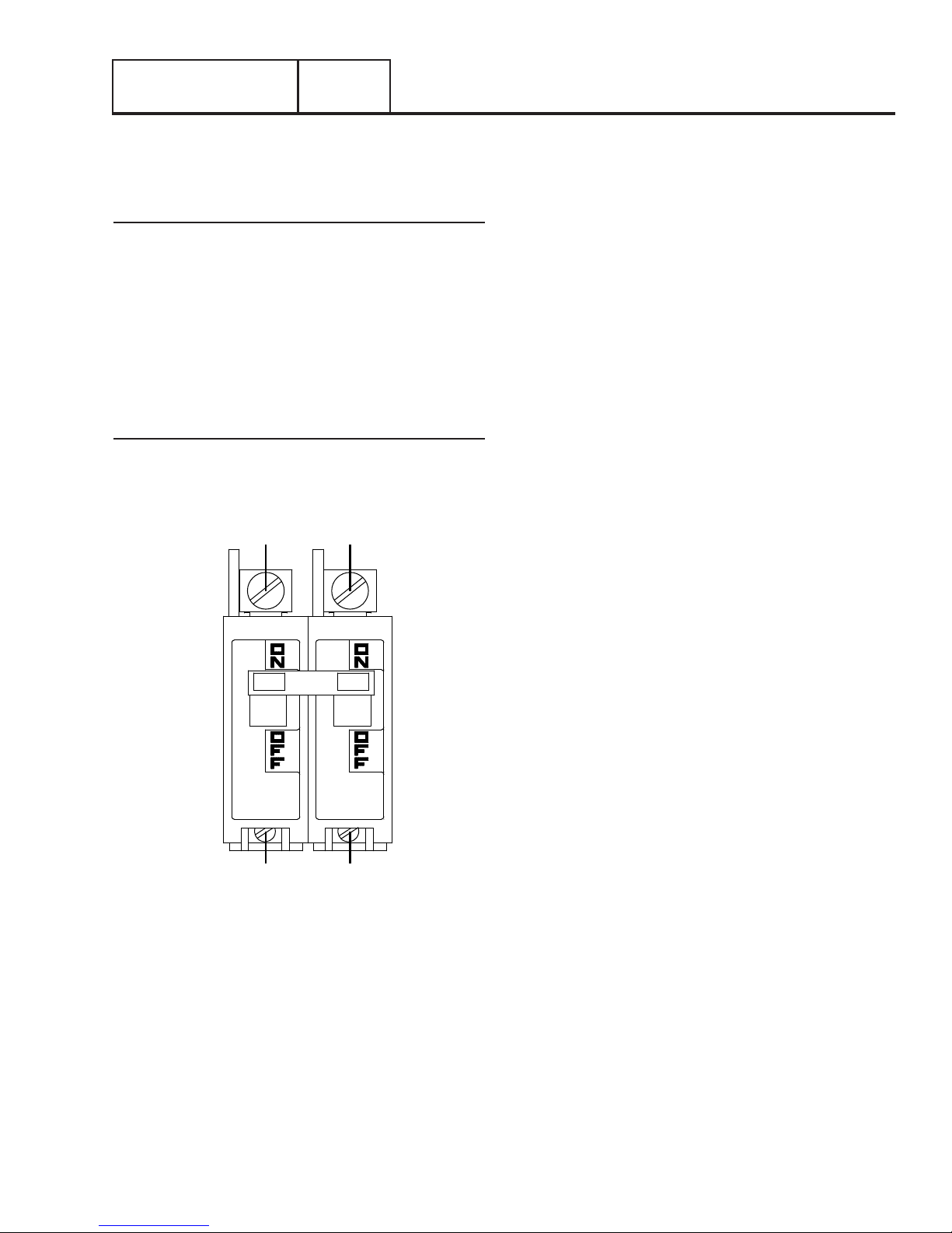
Main Line Circuit Breaker
The main line circuit breaker protects the generator against
electrical overload. Refer to “Specifications” section for the
specific amperage ratings.
Section 2.1
Description and Components
BLUE BLACK
E1 E2
LOAD SIDE
Figure 17. Main Line Circuit Breaker
LINE
Page 25
Page 28
Section 2.2
Operational Analysis
PART 2
AC GENERATORS
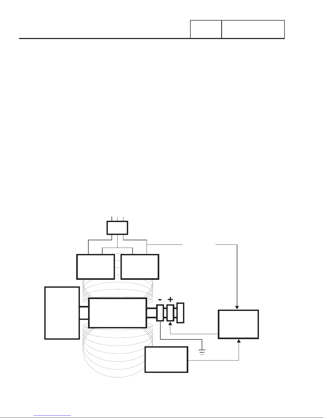
STARTUP
When the engine is started, permanent magnets embedded in
the rotor induce a voltage into (a) the stator AC power windings,
(b) the stator excitation or DPE windings. In an “on-speed”
(engine cranking) condition, this magnetism is capable of
creating approximately one to three volts AC.
ON-SPEED OPERATION
As the engine accelerates, the voltage that is induced into the
stator windings increases rapidly, due to the increasing speed
at which the rotor operates.
FIELD EXCITATION
An AC voltage is induced into the stator excitation (DPE)
windings. The DPE winding circuit is delivered to the voltage
regulator through the two Blue Wires and C1-1 and C1-2.
Unregulated alternating current flows from the winding to the
regulator. The voltage regulator “senses” AC power winding
output voltage and frequency through the Green and White
Wires.
The regulator changes the AC from the excitation winding to DC
Field Excitation. In addition, based on the AC sensing wires,
it regulates the flow of direct current to the rotor. The rectified
and regulated current flow from the regulator is delivered to the
rotor windings through the (+) Red Wire and the positive brush
and slip ring. This excitation voltage flows through the rotor
windings and through the negative (-) slip ring and brush on
the negative (-) Black Wire.
The greater the current flow through the rotor windings, the
more concentrated the lines of flux around the rotor become.
The more concentrated the lines of flux around the rotor that cut
across the stationary stator windings, the greater the voltage
that is induced into the stator windings.
Initially, the AC power winding voltage sensed by the regulator
is low. The regulator reacts by increasing the flow of field
excitation voltage to the rotor until voltage increases to a
desired level. The regulator then maintains the desired voltage.
For example, if voltage exceeds the desired level, the regulator
will decrease the flow of field excitation voltage. Conversely, if
voltage drops below the desired level, the regulator responds by
increasing the flow of excitation current.
AC POWER WINDING OUTPUT
A regulated voltage is induced into the stator AC power windings.
When electrical loads are connected across the AC power
windings to complete the circuit, current can flow in the circuit.
ENGINE DIRECT
DRIVE
STATOR
POWER
WINDING
TO LOAD
MLB
WINDING
MAGNETIC
FIELD
ROTOR
MAGNETIC
FIELD
MLB = MAIN LINE CIRCUIT BREAKER
SENSING
STATOR
POWER
VOLTAGE
REGULATOR
STATOR
EXCITATION
WINDING
Page 26
Figure 18. Operating Diagram
Page 29
AC GENERATORS
PART 2
Troubleshooting Flow Charts
Section 2.2
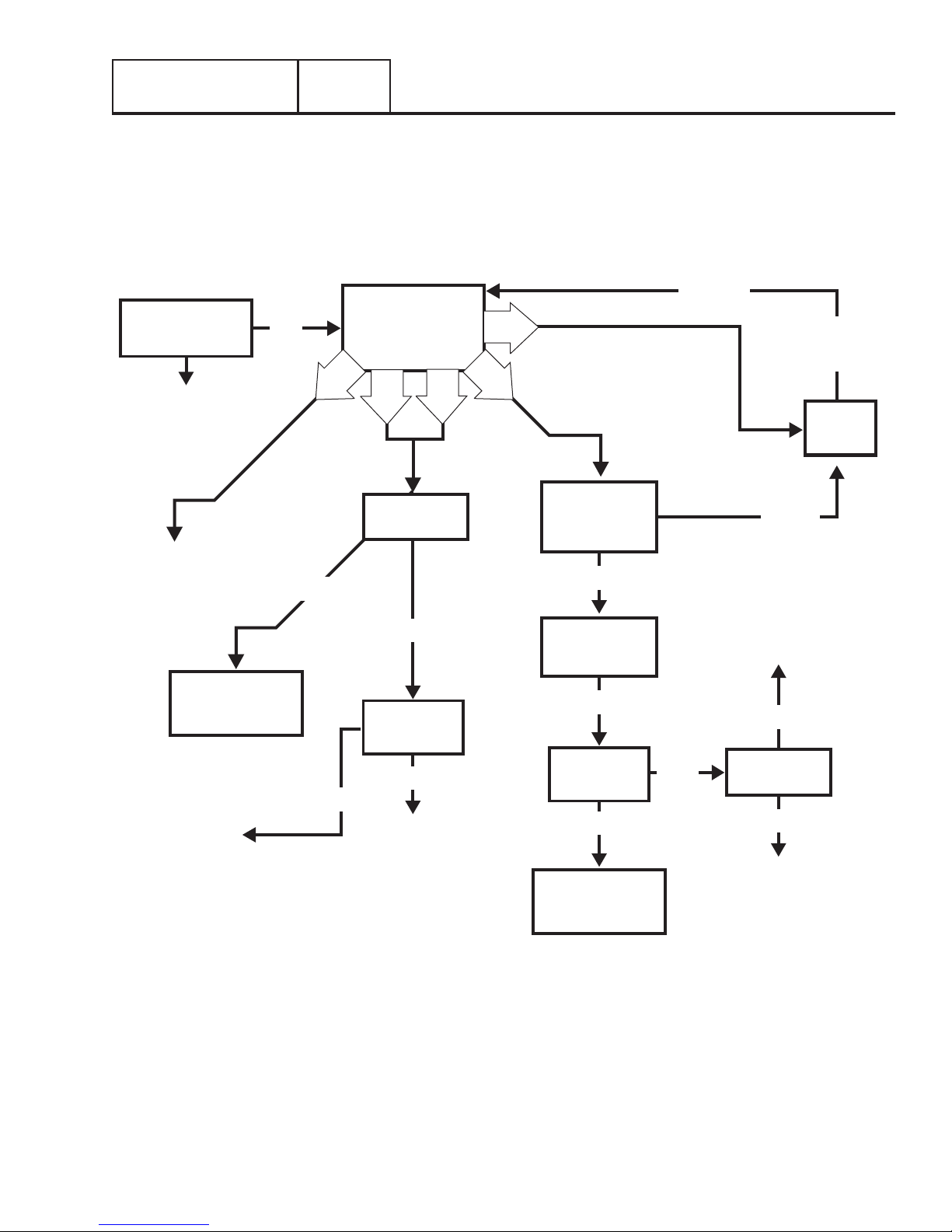
INTRODUCTION
Use the “Flow Charts” in conjunction with the detailed instructions in Section 2.4. Test numbers used in the flow charts correspond
to the numbered tests in Section 2.4. The first step in using the flow charts is to identify the correct problem on the following pages.
For best results, perform all tests in the exact sequence shown in the flow charts.
Problem 1 – Generator Produces Zero Voltage or Residual Voltage
RE-TEST
TEST 1 –
CHECK MAIN
CIRCUIT BREAKER
RESET TO
“ON” OR
REPLACE IF
BAD
REPLACE
VOLTAGE
REGULATOR
ON
GOOD
TEST 4 – PERFORM
FIXED EXCITATION /
ROTOR AMP DRAW
A
B
TEST 9 – TEST
STATOR
C
D
G
TEST 6 –
RESISTANCE
CHECK OF
ROTOR CIRCUIT
BAD
REPAIR
OR REPLACE
FUSES
CHECK
VOM
FUSES
GOOD
PERFORM
INSULATION
RESIST ANCE TEST
REPLACE
STATOR
ONLY
GOOD
BAD
TEST 10 –
TEST ROTOR
ASSEMBLY
BAD
REPLACE
ROTOR AND
STATOR
TEST 7 –
RESIST ANCE TEST
CHECK
BRUSHES &
SLIP RINGS
GOOD
TEST 10 –
TEST ROTOR
ASSEMBLY
GOOD
PERFORM
INSULATION
BAD
REPLACE
ROTOR ONLY
GOOD
TEST 9 – TEST
STATOR
BAD
REPLACE
ROTOR AND
STATOR
Page 27
Page 30
Section 2.3
Troubleshooting Flow Charts
PART 2
AC GENERATORS
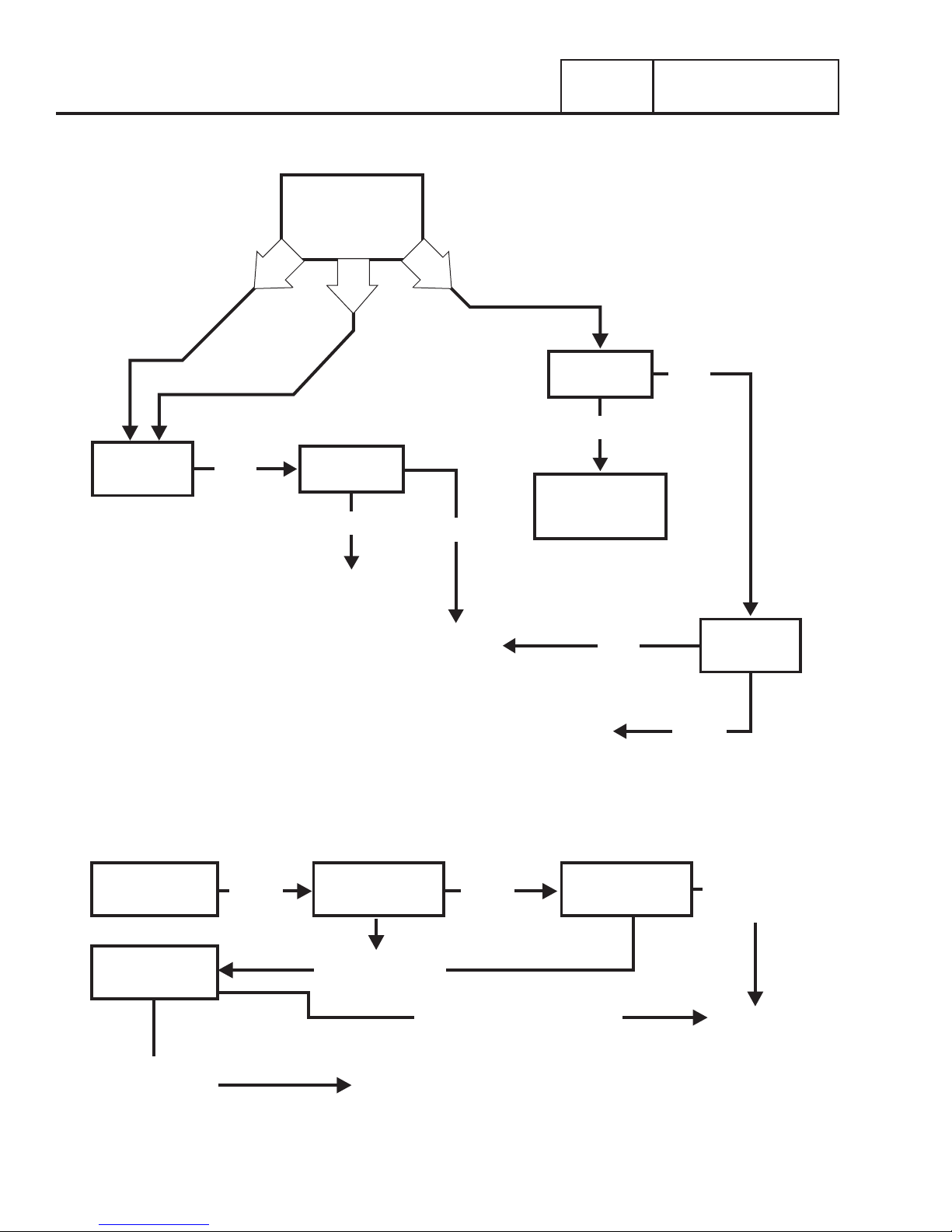
Problem 1 – Generator Produces Zero Voltage or Residual Voltage (Continued)
TEST 4 – PERFORM
FIXED EXCITATION /
ROTOR AMP DRAW
TEST 10 –
TEST ROTOR
ASSEMBLY
BAD
E
H
TEST 9 – TEST
STATOR
GOOD
REPLACE
ROTOR ONLY
F
BAD
REPLACE
ROTOR AND
STATOR
TEST 9 – TEST
STATOR
GOOD
PERFORM ROTOR
INSULATION
RESIST ANCE TEST
BAD
BAD
TEST 10 –
TEST ROTOR
ASSEMBLY
Problem 2 – Generator Produces Low Voltage at No-Load
TEST 11 – CHECK
AC OUTPUT
VOLTAGE
TEST 14 – ADJUST
VOLTAGE
REGULATOR
VOLTAGE O.K.,
BUT VOLTAGE IS
STLL LOW
TEST 12 – CHECK
LOW LOW
AC OUTPUT
FREQUENCY
FREQUENCY O.K.,
BUT VOLTAGE LOW
VOLTAGE AND FREQUENCY O.K.
GO TO “PROBLEM 1”
FLOW CHART - START
AT “TEST 4”
REPLACE
ROTOR ONLY
TEST 13 - ADJUST
ENGINE
GOVERNOR
GOOD
FREQUENCY
AND
VOLTAGE O.K.
STOP TESTS
Page 28
Page 31

AC GENERATORS
PART 2
Troubleshooting Flow Charts
Problem 3 – Generator Produces High Voltage at No-Load
Section 2.3
TEST 11 – CHECK
AC OUTPUT
VOLTAGE
VOLTAGE AND
FREQUENCY O.K.
STOP TESTS
HIGH LOW
TEST 12 – CHECK
AC OUTPUT
FREQUENCY
FREQUENCY O.K.,
BUT VOLTAGE HIGH
TEST 14 – ADJUST
VOLTAGE
REGULATOR
FREQUENCY O.K.,
BUT VOLTAGE IS
STILL HIGH
TEST 13 – ADJUST
ENGINE
GOVERNOR
FREQUENCY AND
VOLTAGE O.K.
STOP TESTS
FREQUENCY O.K.,
BUT VOLTAGE
HIGH
REPLACE DEFECTIVE
VOLTAGE REGULATOR
Problem 4 - Voltage and Frequency Drop Excessively When Loads Are Applied
TEST 16 – CHECK
VOLTAGE AND
FREQUENCY
UNDER LOAD
BOTH
LOW
TEST 15 – CHECK
FOR OVERLAOD
CONDITION
NOT OVERLOADED
TEST 13 – CHECK
AND ADJUST ENGINE
GOVERNOR
GOOD GOOD
DISCONTINUE
TESTING
OVERLOADED
REDUCE LOADS TO
UNIT’S RATED
CAPACITY
LOOK FOR A SHORTED
CONDITION IN A
CONNECTED LOAD OR IN
ONE OF THE LOAD CIRCUITS
GO TO “PROBLEM 23 –
ENGINE STARTS HARD AND
RUNS ROUGH/LACKS POWER”
ENGINE CONDITION GOOD
TEST 9 – CHECK
GOOD
POWER WINDINGS
REPAIR OR REPLACE
STATOR AC
BAD
Page 29
Page 32

Section 2.4
Diagnostic Tests
PART 2
AC GENERATORS
INTRODUCTION
This section familiarizes the service technician with acceptable
procedure for the testing and evaluation of various problems
that can occur on the standby generators with air-cooled
engines. Use this section in conjunction with Section 2.3,
“Troubleshooting Flow Charts.” The numbered tests in this
section correspond with those of Section 2.3.
Some test procedures in this section may require the use of
specialized test equipment, meters or tools. Most tests can be
performed with an inexpensive Volt-Ohm-Milliammeter (VOM).
An AC frequency meter is required where frequency readings
must be taken. To measure AC loads it is acceptable to use a
clamp-on ammeter.
Testing and troubleshooting methods covered in this section
are not exhaustive. No attempt has been made to discuss,
evaluate and advise the home standby service trade of all
conceivable ways in which service and trouble diagnosis must
be performed. Accordingly, anyone who uses a test method
not recommended herein must first satisfy himself that the
procedure or method he has selected will jeopardize neither his
nor the products safety.
SAFETY
Service personnel who work on this equipment should be
aware of the dangers of such equipment. Extremely high and
dangerous voltages are present that can kill or cause serious
injury. Gaseous fuels are highly explosive and can ignite by the
slightest spark. Engine exhaust gases contain deadly carbon
monoxide gas that can cause unconsciousness or even death.
Contact with moving parts can cause serious injury. The list of
hazards is seemingly endless.
When working on this equipment, use common sense and
remain alert at all times. Never work on this equipment
while you are physically or mentally fatigued. If you do not
understand a component, device or system, do not work on it.
Procedure
The generator main circuit breaker is located in the external
customer connection box. If loads are not receiving power,
make sure the breaker is set to “On” or “Closed”.
If you suspect the breaker may have failed, it can be tested as
follows (see Figure 19):
1. Set a Volt-Ohm-Milliammeter (VOM) to its “R x 1” scale
and zero the meter.
2. With the generator shut down, disconnect all wires from
the main circuit breaker terminals, to prevent interaction.
3. With the generator shut down, connect one VOM test
probe to the Blue Wire 11 terminal of the breaker and the
other test probe to the Wire E1 terminal.
4. Set the breaker to its “On” or “Closed” position. The VOM
should read CONTINUITY.
5. Set the breaker to its OFF or “Open” position and the VOM
should indicate INFINITY.
6. Repeat Steps 4 and 5 with the VOM test probes
connected across the breaker’s Black Wire terminal and
the E2 terminal.
Results
1. If the circuit breaker tests good, refer back to flow chart.
2. If the breaker tests bad, it should be replaced.
BLUE BLACK
LINE
AC TR OUBLESHOOTING
It is always good practice to continue to ask questions during
the troubleshooting process. When evaluating the problem
asking some of these questions may help identify the problem
quicker.
•What is the generator supposed to do?
•What fault (Alarm) is shutting the generator down?
•Is the fault a symptom of another problem?
•Does the generator have the same fault consistently?
•When does the fault occur?
•Why would this happen?
•How would this happen?
•What type of test will either prove or disprove the cause of
the fault?
TEST 1 – CHECK MAIN CIRCUIT BREAKER
Discussion
Often the most obvious cause of a problem is overlooked. If the
generator main line circuit breaker is set to OFF or “Open”, no
electrical power will be supplied to electrical loads. If loads are
not receiving power, perhaps the main circuit breaker is open
or has failed.
Page 30
E1 E2
Figure 19. Generator Main Circuit Breaker Test Points
LOAD SIDE
TEST 4 – FIXED EXCITATION /ROTOR AMP
DRA W TEST
Discussion
Supplying a fixed DC current to the rotor will induce a magnetic
field in the rotor. With the generator running, this should create
a proportional voltage output from the stator windings.
Page 33

AC GENERATORS
PART 2
Section 2.4
Diagnostic Tests
Procedure
1. Locate and disconnect the Red Wire and the Black Wire
from the voltage regulator.
2. Set a Volt-Ohm-Meter (VOM) to measure resistance.
3. Connect one meter test lead to the Red brush wire and
connect the other meter test lead to the Black brush wire.
Measure and record the resistance.
4. Set VOM to measure DC voltage.
5. Connect one meter test lead to the positive post of the
battery and the other meter test lead to the negative post
of the battery. Measure and record the voltage indicated.
6. Using a jumper wire similar to Figure 20, connect a
jumper wire to the disconnected female connector Red
Wire and the positive post of the battery.
7. Using a jumper wire similar to Figure 20, connect a
jumper wire to the disconnected female connector Black
Wire and the negative post of the battery.
8. Disconnect the C1 connector from the voltage regulator
9. Set a VOM to measure AC voltage.
10. Connect meter test leads across C1 Terminals Points 1
(Blue Wire) and 2 (Blue Wire). Refer to Figure 21
11. Set the AUTO-OFF-MANUAL switch to the MANUAL
position.
12. Once the engine reaches rated speed, measure and
record the voltage.
13. Set the AUTO-OFF-MANUAL switch to the OFF position.
14. Connect meter test leads across points 3 (Green Wire)
and 4 (White Wire). Refer to Figure 21
15. Set the AUTO-OFF-MANUAL switch to the MANUAL
position.
16. Once the engine reaches rated speed, measure and
record the voltage.
17. Set the AUTO-OFF-MANUAL switch to the OFF position.
BLACK WIRE
TO BRUSHES
MALE SPADE TERMINALS
(INSULATED)
5 AMP FUSE
-
RED WIRE
TO BRUSHES
(INSULATED)
FUSE
+
BATTERY
Figure 20. Jumper Wires Connected
C1
1
3
4
GREEN
WHITE
18. Remove the jumper wire that was connected in Step 5
from the Red Wire.
19. Set the VOM to measure DC amperage and re-locate the
test leads to the correct spot.
20. Connect the negative meter test lead to the disconnected
Red Wire (Female Side). Connect the positive meter test
lead to the positive post of the battery. Measure and
record the static DC amperage
2
BLUE
STATOR
BLUE
Figure 21. C1 Test Points
Results: A B C D E F G H
Blue and Blue
White and Green
Static Rotor Amp Draw 0.22 - 0.46 0.22 - 0.46 0.22 - 0.46
Running Rotor Amp Draw 0.22 - 0.46 0.22 - 0.46 0.22 - 0.46
Note: Actual values measured may vary by as much as .5 amps; depending on the type and quality of meter used, the condition of the unit, and how good the
connection is between the test leads and test points.
ç
MATCH RESULTS WITH LETTER AND REFER TO FLOW CHART IN SECTION 2.3 “Problem 1”
Above 20
VAC
Above 20
VAC
Table 2. Test 4 Results – Fixed Excitation Test
Above 20
VAC
Below 20
VAC
Below 50
VAC
Above 50
VAC
Zero or
Residual
Volts
Zero or
Residual
Volts
Zero Current
Draw
Zero Current
Draw
Below 20
VAC
Below 20
VAC
Above 1 Amp 0.22 - 0.46
Above 1 Amp 0.22 - 0.46
Below 50
VAC
Below 50
VAC
Above 20
VAC
Above 20
VAC
Zero Current
Draw
Zero Current
Draw
è
Below 20
VAC
Below 20
VAC
0.22 - 0.46
Above 1 Amp
Page 31
Page 34

Section 2.4
Diagnostic Tests
PART 2
AC GENERATORS
21. Set the AUTO-OFF-MANUAL switch to the MANUAL
position.
22. Measure and record the running DC amperage.
23. Set the AUTO-OFF-MANUAL switch to the OFF position
and reconnect the wires to the voltage regulator.
Table 3. Test 4 Results Worksheet
Test Point Results
Rotor Resistance
Battery Voltage
Blue to Blue Voltage
White and Blue Voltage
Static Rotor Amp Draw
Running Rotor Amp Draw
Column Identified
Results
1. Using the values recorded in the above procedures,
compare the results to Table 2 “Test 4 Results – Fixed
Excitation Test”. Determine the appropriate lettered
column to use and refer back to the flow chart. The
rotor amp draws are a calculated amp draw and actual
amperage readings may vary depending on the resistance
of the rotor and battery voltage.
Note: To calculate rotor amp draw take the battery voltage
applied, divided by the actual resistance reading of the
rotor. Rotor resistance can be measured between the RED
and BLACK wires going to the voltage regulator.
12.9VDC
50 Ohms x .258 DC Amps
Ohms
VDC
VAC
VAC
Amps
Amps
2. If the VOM did not indicate the proper resistance, refer
back to flow chart.
TEST 7 – CHECK BRUSHES AND SLIP RINGS
Discussion
The brushes and slip rings function to provide an electrical
connection for excitation current from the stationary
components to the rotating rotor. Made of a special long
lasting material, brushes seldom wear out or fail. However,
slip rings can develop a tarnish or film that can inhibit or offer
a resistance to the flow of current. Such a non-conducting
film usually develops during non-operating periods. Broken or
disconnected wiring can also cause loss of excitation current
to the rotor.
Procedure
1. Disassemble the Generator until the brushes and slip rings
are exposed. Refer to Section 5.1 “Major Disassembly.”
2. Inspect the brush wires and verify they are secured and
properly connected.
3. Inspect the brush assembly for excessive wear, or
damage.
4. Inspect the rotor slip rings. If their appearance is dull or
tarnished, polish with a fine grade abrasive material.
Do not use metallic grit to polish slip rings. This may
cause irreversible damage to the rotor.
5. The Black Wire, located on the negative brush terminal,
provides an electrical connection to the voltage regulator.
To test this wire for an OPEN condition, remove the Black
Wire from the brush assembly.
6. Set Volt-Ohm-Milliammeter (VOM) to measure resistance.
TEST 6 – RESISTANCE CHECK OF ROTOR
CIRCUIT
Procedure
1. Locate and disconnect the Red and Black wires from the
voltage regulator.
2. Set a Volt-Ohm-Milliammeter (VOM) to measure
resistance.
3. Connect meter test leads across the female Red and Black
wires at connector disconnected in Step 1. Measure and
record the resistance.
Results
1. If the VOM indicate a resistance of approximately 40
ohms ± 20 ohms, verify rotor amp draw.
Page 32
7. Connect one meter test lead to the Black Wire at the brush
assembly and connect the other meter test lead to the
Black wire at the voltage regulator.
•If the VOM indicated INFINITY, repair or replace the Black
Wire between the negative slip ring and the voltage regulator.
•If the VOM indicated CONTINUITY, continue to Step 8.
8. Disconnect the Red Wire from the brushes.
10. Connect one meter test lead to the Red Wire disconnected
at the brushes and the other meter test lead to the Red
wire disconnected at the voltage regulator.
Results
1. Repair, replace, or reconnect wires as necessary.
2. Replace any damage slip rings or brush holder.
3. Clean and polish slip rings as required.
Page 35

AC GENERATORS
PART 2
Section 2.4
Diagnostic Tests
TEST 9 – TEST THE STATOR
Discussion
This test will use a Volt-Ohm-Milliammeter (VOM) to test the
stator windings for the following faults:
•An OPEN circuit condition
•A “shor t-to-ground” condition
•A shor t circuit between windings
Table 7 has been provided to record the results of the following
procedure. These results may be required when requesting
factory support.
Additional copies of Table 7 can be found in Appendix A
“Supplemental Worksheets” at the back of this manual.
Note: It is the recommendation of the factory to perform
this test procedure using piercing probes on the wire
side of the connector. Testing inside the connector itself
can cause damage to the unit resulting in poor or loose
connections.
Stator Resistances
•Power Windings
White/Blue = .173 Ohms
White/Black = .173 Ohms
Blue/Black = .346 Ohms
•Sensing Winding
Green/White = .064 Ohms
•DPE Winding
Blue/Blue = 1.158 Ohms
Table 4. Test Points – Resistance Tests
Test Point A Test Point B
Stator Lead Blue Wire Stator Lead Black Wire
Stator Lead Blue Wire C1 Pin 3 (White Wire)
Stator Lead Blue Wire C1 Pin 4 (Green Wire)
Test Windings for a Short to Ground
6. Make sure all stator leads are isolated from each other
and are not touching the frame.
7. Measure and record the resistance values for each set
of windings between the A and B test points as shown in
Table 5. Record the results in Table 7.
Table 5. Test Points – Shorts to Ground
Test Point A Test Point B
Stator Lead Blue Wire Ground
Stator Lead Black Wire Ground
C1 Pin 1 Wire 44 (Blue Wire) Ground
C1 Pin 4 (Green Wire) Ground
Test For A Short Circuit Between Windings
8. Measure and record the resistance values for each set
of windings between the A and B test points as shown in
Table 6. Record the results in Table 7.
Table 6. Test Points – Shorted Condition
Procedure: Resistance Test
1. Disconnect the Blue and Black Wires from the main line
circuit breaker (MLCB).
2. Disconnect the C1 connector from the voltage regulator.
3. Make sure all of the disconnected leads are isolated from
each other and are not touching the frame during the test.
4. Set the VOM to measure resistance.
5. Measure and record the resistance values for each set
of windings between the A and B test points as shown in
Table 4. Record the results in Table 7.
C1
1
WHITE
3
4
GREEN
BLUE
2
BLUE
Figure 22. Stator Lead Connections
STATOR
Test Point A Test Point B
C1 Pin 1 (Blue Wire) Stator Lead Blue Wire
Table 7. Stator Test Results
Test Point A Test Point B Results
Resistance Tests
Stator Lead Blue Wire Stator Lead Black Wire
Stator Lead Blue Wire C1 Pin 3 (White Wire)
Stator Lead Blue Wire C1 Pin 4 (Green Wire)
Shorts to Ground
Stator Lead Blue Wire Ground
Stator Lead Black Wire Ground
C1 Pin 1 Wire 44 (Blue Wire) Ground
C1 Pin 4 (Green Wire) Ground
Shorted Condition
C1 Pin 1 (Blue Wire) Stator Lead Blue Wire
Note: These results may be needed when requesting
factory support.
Note: Stator winding resistance values are very low and
some VOM’s will not read such a low resistance, and
will simply indicate CONTINUITY. The manufacturer
recommends a high quality digital type meter capable of
reading a very low resistance.
Page 33
Page 36

Section 2.4
Diagnostic Tests
Results
PART 2
AC GENERATORS
1. Resistance Test: If the VOM indicated a very high
resistance or INFINITY, the windings are open or partially
open.
2. Grounded Condition: Any resistance value other than
INFINITY indicates a grounded winding.
3. Shorted Condition: Any resistance value other than
INFINITY indicates a shorted winding.
Note: If the winding tests good, perform an insulation
resistance test. If the winding fails the insulation
resistance test (using a meg-ohm-meter), clean and dry the
stator. Then, repeat the insulation resistance test. If the
winding fails the second resistance test (after cleaning and
drying), replace the stator assembly.
TEST 10 – TEST ROTOR ASSEMBLY
Discussion
A rotor having open windings will cause loss of excitation
current flow and as a result generator AC output voltage will
drop to “residual” voltage. A “shorted” rotor winding can result
in a low voltage condition.
Procedure
DANGER! Use extreme caution during this test. The
generator will be running. High and dangerous voltages
will be present at the test terminals. Connect meter
test clamps to the high voltage terminals while the
generator is shut down. Stay clear of power terminals
during the test. Make sure meter clamps are securely
attached and will not shake loose.
Procedure
1. With the engine shut down, connect the AC voltmeter test
leads across the Blue and Black Wire terminals of the
generator main circuit breaker. These connections will
permit line-to-line voltages to be read.
2. Set the generator main circuit breaker to its OFF or “Open”
position. This test will be conducted with the generator
running at no-load.
3. Start the generator, let it stabilize and warm up for a
minute or two.
4. Take the meter reading. On unit’s having a rated line-toline voltage of 240 volts, the no-load voltage should be
about 242-252 volts AC.
5. Shut the engine down and remove the meter test leads.
1. Remove the brush assembly from the slip rings to prevent
interaction.
2. Set a Volt-Ohm-Milliammeter (VOM) to measure
resistance.
3. Connect one meter test lead to the positive slip ring
(nearest the rotor bearing) and the other test lead to the
negative slip ring, measure and record the resistance.
4. Connect one meter test lead to the positive slip ring and
connect the other meter test lead to a clean frame ground,
measure and record the resistance.
Results
1. If the VOM indicated a resistance of 40 ohms +/- 20
ohms, (GOOD) refer back to flow chart.
2. If the VOM did not indicate a resistance within the allowed
tolerances, replace rotor.
3. If the VOM indicated CONTINUITY in Step 4, replace the
rotor assembly.
TEST 11 – CHECK AC OUTPUT VOLTAGE
Discussion
A Volt-Ohm-Milliammeter (VOM) may be used to check the
generator output voltage. Output voltage may be checked at the
unit’s main circuit breaker terminals. Refer to the unit’s DATA
PLATE for rated line-to-line and line-to-neutral voltages.
Page 34
Results
1. If zero volts or residual voltage is indicated, proceed to
Test 4.
2. If the voltage reading is higher than residual, but is lower
than the stated limits, go to Test 12.
3. If a high voltage is indicated, go on to Test 12.
NOTE: “Residual” voltage may be defined as the voltage
that is produced by rotor residual magnetism alone.
The amount of voltage induced into the stator AC power
windings by residual voltage alone will be approximately 2
to 16 volts AC. If a unit is supplying residual voltage only,
either DC field excitation voltage is not reaching the rotor
or the rotor windings are open and the excitation voltage
cannot pass.
TEST 12 – CHECK AC OUTPUT FREQUENCY
Discussion
The generator AC frequency is proportional to the operating
speed of the rotor. The 2-pole rotor will supply a 60 Hertz
AC frequency at 3600 rpm. The unit’s AC output voltage is
proportional to the AC frequency. For example, a unit rated
240 volts (line-to-line) will supply that rated voltage (plus or
minus 2 percent) at a frequency of 60 Hertz. If, for any reason,
the frequency should drop to 30 Hertz, the line-to-line voltage
will drop to a matching voltage of 120 volts AC. Thus, if the
AC voltage output is high or low and the AC frequency is
correspondingly high or low, the engine speed governor may
require adjustment.
Page 37

AC GENERATORS
PART 2
Section 2.4
Diagnostic Tests
Procedure
1. Connect an accurate AC frequency meter across the Blue
and Black Wire terminals of the generator main line circuit
breaker (see Figure 19).
2. Start the engine, let it stabilize and warm up at no-load.
3. When engine has stabilized, read the frequency meter. The
no-load frequency should be about 61-63 Hertz.
Results
1. Refer back to flow chart.
2. If frequency and voltage are both good, tests may be
discontinued.
TEST 13 – ADJUST ENGINE GOVERNOR
If both AC frequency and voltage are correspondingly high or
low, adjust the engine governor as follows:
The engine must be OFF to perform steps 1 and 2.
1. Loosen the governor clamp bolt (13mm). See Figure 23.
2. Hold the governor lever at its wide open throttle position
(clockwise), and rotate the governor shaft clockwise as
far as it will go. Then, tighten the governor lever clamp
bolt to 70 inch-pounds (8 N-m).
3. Start the generator; let it stabilize and warm up at no-load.
4. Connect a frequency meter across the generators AC
output leads.
5. Turn the adjust nut to obtain a frequency reading of 62.5
Hz.
TEST 14 – ADJUST VOLTAGE REGULATOR
Procedure
1. Remove two screws holding down the voltage regulator
(AVR).
2. Leave the C1 connector and the brush connections
connected.
3. Set VOM (Volt-Ohm-Meter) to measure AC voltage.
4. Connect meter test leads across the main breaker.
240
Figure 24. VOM Test Leads Connected to the main breaker.
6. Ensure all material is clear of the alternator before
proceeding.
7. Set the AUTO-OFF-MANUAL switch to the MANUAL
position.
8. Refer to Figure 25 for location of adjustment screw.
9. Adjusting screw clockwise will increase voltage, adjusting
counterclockwise will lower the voltage.
Results
1. If no change in voltage while adjusting refer back to flow
chart.
Figure 23. Engine Governor Adjustment Points
2. If voltage is correct, stop testing.
Figure 25. Voltage Regulator Adjustment Screw
Page 35
Page 38

Section 2.4
Diagnostic Tests
PART 2
AC GENERATORS
TEST 15 – CHECK FOR OVERLOAD
CONDITION
Discussion
An “overload” condition is one in which the generator rated
wattage/amperage capacity has been exceeded. To test for an
overload condition on an installed unit, the best method is to
use an ammeter. See “Measuring Current” in Section 1.2.
Procedure
Use a clamp-on ammeter to measure load current draw, with the
generator running and all normal electrical loads turned on.
Results
1. If the unit is overloaded, reduce loads to the unit’s rated
capacity.
2. If unit is not overloaded, but rpm and frequency drop
excessively when loads are applied, go to Test 16.
TEST 16 – CHECK VOLTAGE AND
FREQUENCY UNDER LOAD
Discussion
It is possible for the generator AC output frequency and voltage
to be good at no-load, but they may drop excessively when
electrical loads are applied. This condition, in which voltage
and frequency drop excessively when loads are applied, can
be caused by (a) overloading the generator, (b) loss of engine
power, or (c) a shorted condition in the stator windings or in
one or more connected loads.
Procedure
1. Connect an accurate AC frequency meter and an AC
voltmeter across the stator AC power winding leads.
2. Start the engine, let it stabilize and warm-up.
3. Apply electrical loads to the generator equal to the rated
capacity of the unit.
4. Check the AC frequency and voltage. Frequency should
not drop below approximately 58-59 Hertz. Voltage
should not drop below about 230 volts (plus or minus 2
percent).
Results
1. If frequency and voltage drop excessively under load, go
to Test 15.
2. If frequency and voltage under load are good,
discontinue tests.
Page 36
Page 39

PART 3
TRANSFER SWITCH
PART 3 – Transfer Switch ..................................................37
Section 3.1 – Description and Components
General
................................................................. 38
Enclosure ............................................................. 38
EZ Transfer Operator ............................................. 38
Fuse Holder .......................................................... 38
Section 3.2 – Operational Analysis .................................... 39
Utility Voltage Present ...........................................39
Transfer to Standby ............................................... 39
Transfer to Utility ................................................... 39
Section 3.3 – Troubleshooting Flowcharts ......................... 41
Introduction .......................................................... 41
Problem 10 – In Automatic Mode,
No Transfer to Standby ......................................... 41
Problem 11 – In Automatic Mode, Generator
Starts When Loss of Utility Occurs, Generator
Shuts Down When Utility Returns But There is No
Retransfer To Utility Power OR Generator Transfers
to Standby During Exercise or in Manual Mode ...... 41
Problem 12 – Blown F1 or F2 Fuse ........................42
Problem 13 – Blown T1 Fuse ................................ 42
Problem 14 – Unit Starts and Transfer Occurs
When Utility Power is On .......................................42
....................... 38
Section 3.4 – Diagnostic Tests .......................................... 43
Introduction
Safety
Transfer Switch Troubleshooting ..........................43
Test 27 – Check Generator Voltage at
Transfer Switch ...................................... 43
Test 28 – Test Transfer Operator ............................43
Test 29 – Check 15B/194 Circuit .......................... 43
Test 30 – Check Wire 23 Circuit ............................ 44
Test 32 – Check Fuses F1 and F2 .......................... 44
Test 33 – Check N1 and N2 Wiring ........................ 45
Test 35 – Check Fuse F3 ...................................... 45
Test 36 – Check T1 Wiring .................................... 45
Test 38 – Check N1 and N2 Voltage ...................... 46
Test 39 – Check Utility Sense Voltage .................... 46
Test 40 – Check Utility Voltage at Transfer Switch .. 46
Test 41 – Check Utility Sensing Voltage
at the Controller ..................................... 46
.......................................................... 43
................................................................... 43
Page 37
Page 40

Section 3.1
Description and Components
PART 3
TRANSFER SWITCH
GENERAL
The 50 amp transfer switch is designed to operate in conjunction
with all product which utilizes the Wire 194/15B and Wire 23
control systems. Utility voltage and the control panel on the
generator controls sequence delays. The AUTO-OFF-MANUAL
switch must be in the AUTO position for automatic operation of
the transfer switch.
ENCLOSURE
The standard switch enclosure is a National Electrical
Manufacturer’s Association (NEMA) UL Type 1.
EZ TRANSFER OPERAT OR
The EZ Transfer Operator is a rotary device that actuates the
arms that push two standard 2-pole breakers, transferring
the load from Utility to Generator. The operator returns to
a “Neutral” position so the arms move freely and allow the
manual operation of the breakers.
The operator is suited for single-phase applications only, when
the single-phase NEUTRAL line is to be connected to a Neutral
Lug and is not to be switched.
Internal Components
Three components make up the operator: the servomotor, Limit
Switch 1 (LS1), and Limit Switch 2 (LS2). The servomotor is
responsible for changing the position of the breakers inside
the switch. Both limit switches are responsible for interrupting
current flow to the servomotor once the transfer cycle is
complete.
FUSE HOLDER
Utility N1 and N2
N1 and N2 provide the Utility voltage-sensing signal to the
controller. The controller utilizes the sensing circuit as follows:
•If Utility source voltage should drop below 65% of nominal
for ten seconds, the controller’s logic will initiate automatic
cranking and startup. The controller will transfer the switch
to the Standby position after a five second engine warm-up
timer.
Load T1
Wire T1, connected to the Load side of the switch, provides 120
VAC for the battery charging. The charger maintains battery
voltage anytime the load terminals have voltage available.
N1
N2
T1
Figure 27. Fuse Holder
Figure 26. EZ Transfer Operator
Page 38
5 AMP 600V RATING
FAST ACTING
BUSSMANN PART# BBS-5
Figure 28. Fuse
Page 41

TRANSFER SWITCH
PART 3
Section 3.2
Operational Analysis
UTILITY VOLTA GE PRESENT
When Utility voltage is present, the circuit may be briefly
described as:
•Battery voltage is available to B+ (194 or 15B) and B- (Wire
0) from the generator.
•The internal K1 relay is de-energized.
•K1 contacts 11 and 13 are in their normally closed state.
•K1 contacts 8 and 7 are in their normally open state.
TRANSFER TO ST ANDBY
With the Generator running during a Utility failure, the circuit
may be described as:
•Battery voltage is available to B+ and B- from the generator.
•A ground has been applied to Terminal XFER (Wire 23) via
the generator controller.
BLACK
M
•The K1 relay is energized, contacts 11 and 13 open, and
8 and 7 close completing a path for current to flow to the
servo motor.
•The servo motor will operate till LS2 is mechanically
opened, interrupting the current flow to the servo motor.
TRANSFER TO UTILITY
With the Generator running and Utility restored, the circuit
maybe described as:
•Battery voltage is available to B+ and B- from the generator.
•The return to utility timer has expired and the ground has
been removed from the XFER terminal (Wire 23).
•The K1 relay will de-energize, contacts 11 and 13 will close,
and 8 and 7 will open completing a path for current to flow
to the servo motor.
•The servo motor will operate till LS1 is mechanically opened
and LS2 will mechanically close.
B -
XFER -
B
RED
M = SERVO MOTOR
K1 = TRANSFER RELAY
LS1 = LIMIT SWITCH
LS2 = LIMIT SWITCH
LS2
K1
9
11 13
2
3
1
K1
8
K1
A
B +
10
LS1
1
2
3
7
6 4
Figure 29. EZ Operator Electrical Schematic
Page 39
Page 42

NOTES
PART 3
TRANSFER SWITCH
Page 40
Page 43

TRANSFER SWITCH
PART 3
Troubleshooting Flowcharts
Section 3.3
INTRODUCTION
Use the “Flow Charts” in conjunction with the detailed instructions in Section 3.4. Test numbers used in the flow charts correspond
to the numbered tests in Section 3.4. The first step in using the flow charts is to identify the correct problem on the following pages.
For best results, perform all tests in the exact sequence shown in the flow charts.
Problem 10 – In Automatic Mode, No Transfer to Standby
TEST 27 – CHECK
VOLTAGE AT
TRANSFER
SWITCH
GOOD
BAD
FIND CAUSE OF NO AC OUTPUT TO
TRANSFER SWITCH FROM GENERATOR
TEST 28 – TEST
TRANSFER
OPERATOR
GOOD
TEST 30 –
CHECK WIRE 23
CIRCUIT
GOOD
REPLACE
CONTROLLER
BAD
BAD
TEST 29 –
CHECK WIRE
15B/194 CIRCUIT
BAD
REPAIR OR
REPLACE AS
NEEDED
GOOD
REPLACE
TRANSFER
OPERATOR
Problem 11 – In Automatic Mode, Generator Starts When Loss of Utility Occurs, Generator
Shuts Down When Utility Returns But There Is No Retransfer To Utility Power
OR
Generator Transfers to Standby During Excercise or in Manual Mode
TEST 28 – TEST
TRANSFER
OPERATOR
GOOD
TEST 30 –
CHECK WIRE 23
CIRCUIT
GOOD
RE-TEST
BAD
BAD
REPLACE
TRANSFER
OPERATOR
REPAIR OR REPLACE AS NEEDED
Page 41
Page 44

Section 3.3
Troubleshooting Flowcharts
PART 3
Problem 12 – Blown F1 or F2 Fuse
TRANSFER SWITCH
TEST 32 – CHECK
FUSE F1 & F2
GOOD
FINISH
TEST 35 – CHECK
FUSE F3 (T1)
GOOD
STOP TESTING
BAD
TEST 33 – CHECK
N1 & N2 WIRING
BAD
REPAIR OR REPLACE
WIRING
Problem 13 – Blown T1 Fuse
BAD
TEST 36 – CHECK
T1 WIRING
BAD
REPAIR OR REPLACE
WIRING
GOOD
GOOD
INSPECT/REPLACE
CONTROLLER
REPLACE CONTROLLER
Problem 14 – Unit Starts and Transfer Occurs When Utility Power Is On
TEST 38 –
CHECK N1 & N2
VOLTAGE
BAD
TEST 39 – CHECK
UTILITY SENSE
VOLTAGE
GOOD
REPAIR N1/N2 OPEN WIRING
BETWEEN TRANSFER
SWITCH AND GENERATOR
Page 42
BAD
GOOD
TEST 32 –
CHECK FUSE
F1 & F2
BAD
REPLACE
GO TO PROBLEM 7
TEST 41 – CHECK
UTILITY SENSING
VOLTAGE AT
CONTROLLER
GOOD
REPAIR OR REPLACE WIRE
N1A/N2A BETWEEN N1/N2
LUGS AND FUSE HOLDER
GOOD
BAD
TEST 38 –
CHECK N1 AND
N2 VOLT A GE
REPAIR OR
REPLACE
GOOD
WIRING
REPLACE
CONTROLLER
BAD
CORRECT
UTILITY
SOURCE
VOLTAGE
Page 45

TRANSFER SWITCH
PART 3
Section 3.4
Diagnostic Tests
INTRODUCTION
This section familiarizes the service technician with acceptable
procedure for the testing and evaluation of various problems
that can occur on pre-packaged transfer switches. Use this
section in conjunction with Section 3.3, “Troubleshooting Flow
Charts.” The numbered tests in this section correspond with
those of Section 3.3.
Some test procedures in this section may require the use of
specialized test equipment, meters or tools. Most tests can be
performed with an inexpensive volt-ohm-meter (VOM). An AC
frequency meter is required, where frequency readings must be
taken. To measure AC loads it is acceptable to use a clamp-on
ammeter.
Testing and troubleshooting methods covered in this section
are not exhaustive. No attempt has been made to discuss,
evaluate and advise the home standby service trade of all
conceivable ways in which service and trouble diagnosis must
be performed. Accordingly, anyone who uses a test method
not recommended herein must first satisfy himself that the
procedure or method he has selected will jeopardize neither his
nor the products safety.
SAFETY
Service personnel who work on this equipment should be
aware of the dangers of such equipment. Extremely high and
dangerous voltages are present that can kill or cause serious
injury. Gaseous fuels are highly explosive and can ignite by the
slightest spark. Engine exhaust gases contain deadly carbon
monoxide gas that can cause unconsciousness or even death.
Contact with moving parts can cause serious injury. The list of
hazards is seemingly endless.
When working on this equipment, use common sense and
remain alert at all times. Never work on this equipment
while you are physically or mentally fatigued. If you do not
understand a component, device or system, do not work on it.
TEST 27 – CHECK GENERATOR VOLTAGE AT
TRANSFER SWITCH
Procedure
1. Set Volt-Ohm-Milliammeter (VOM) to measure AC voltage
2. With the generator running check generator voltage at the
generator's circuit breaker in the transfer switch. Measure
and record the voltage.
Results
1. If the VOM indicated approximately 240 VAC, refer back to
flow chart.
2. If the VOM did not indicate the correct AC voltage,
investigate the cause of the no AC output.
TEST 28 – TEST TRANSFER OPERATOR
Procedure
1. Using a jumper wire connected to a common ground;
connect a ground to the XFER terminal on the operator.
Observe the rotation of the operator.
2. Disconnect ground from XFER terminal and observe the
rotation of the operator.
Results
1. If the operator transferred to “Standby” when XFER was
grounded and re-transferred back to “Utility” when XFER
was ungrounded, the operator is functioning correctly.
2. If the operator failed to transfer to either “Standby” or
“Utility” positions, refer back to flow chart.
TRANSFER SWITCH TROUBLESHOOTING
It is always good practice to continue to ask questions during
the troubleshooting process. When evaluating the problem
asking some of these questions may help identify the problem
quicker.
•What is the transfer switch doing?
•What was the transfer switch supposed to do?
•Does the transfer switch have the same fault consistently,
and when does it occur?
•Who is controlling it?
•Exactly what is occurring?
•When is it happening?
•Why would this happen?
•How would this happen?
•What type of test will either prove or disprove the cause of
the fault?
TEST 29 – CHECK 15B/194 CIRCUIT
Procedure
1. Set a Volt-Ohm-Milliammeter (VOM) to measure DC
voltage.
2. Connect one meter test lead to BAT + and connect the
other meter test lead to BAT - on the operator. Measure
and record the voltage.
a. If the VOM indicated battery voltage, replace transfer
operator.
b. If the VOM did not indicate battery voltage, proceed to
Step 3.
3. Connect one meter test lead to Wire 15B and the other
meter test lead to Wire 0 located on the customer
connection block. Measure and record the voltage.
a. If the VOM indicated battery voltage, repair or replace
the wiring between the transfer switch and the
generator.
Page 43
Page 46

Section 3.4
Diagnostic Tests
PART 3
TRANSFER SWITCH
b. If the VOM did not indicate battery voltage, proceed to
Step 4.
4. Connect one meter test lead to Wire 15B and the other
meter test lead to a clean frame ground. Measure and
record the voltage.
a. If the VOM indicated battery voltage, repair or replace
Wire 0 in the generator.
b. If the VOM did not indicate battery voltage, repair or
replace Wire 15B in the generator.
Results
Refer back to flow chart.
TEST 30 – CHECK WIRE 23 CIRCUIT
Procedure
1. Set a Volt-Ohm-Milliammeter (VOM) to measure DC
voltage
Note: Generator should not be running for this part of the
procedure.
2. Connect one meter test lead to the XFER terminal on
the operator and the other meter test lead to the BAT +
terminal. Measure and record the voltage.
a. If the VOM indicated battery voltage and the transfer
operator transferred the load to the Generator, Wire 23
circuit is shorted to ground, proceed to Step 3.
b. If the VOM did not indicate battery voltage, proceed to
Step 8
3. Disconnect the customer supplied Wire 23 from the
customer connection block in the generator.
10. Once the generator has star ted and warmed up, connect
one meter test lead to the XFER terminal and the other
meter test lead to the BAT + terminal in the transfer
switch. Measure and record the voltage.
a. If the VOM indicated battery voltage, stop testing.
b. If the VOM did not indicate battery voltage, proceed to
Step 11.
11. Connect one meter test lead to Wire 23 and the other
meter test lead to Wire 15B in the customer connection
block. Measure and record the voltage.
a. If the VOM indicated battery voltage, repair or replace
Wire 23 between the transfer switch and the generator.
b. If the VOM did not indicate battery voltage, proceed to
Step 11.
12. Locate and disconnect the J2 connector from the
controller.
13. Set VOM to measure resistance.
14. Connect one meter test lead to J2-5 (Wire 23) and the
other meter test to Wire 23 connected at the customer
connection terminal block.
a. If the VOM indicated in CONTINUITY, replace controller.
b. If the VOM indicated INFINITE, repair or replace Wire 23
between the J2 connector and the customer connection
terminal block.
Results
Refer back to flow chart.
TEST 32 – CHECK FUSES F1 AND F2
4. Connect one meter test lead to Wire 23 on the customer
connection block and the other meter test lead to Wire
15B.
a. If the VOM indicated battery voltage, proceed to Step 5.
b. If the VOM did not indicate battery voltage, repair or
replace the shorted Wire 23 between the switch and
the generator.
5. Locate and disconnect the J2 connector from the
controller.
6. Set the VOM to measure resistance.
7. Connect one meter test lead to a clean frame ground
and the other meter test lead Wire 23 and the customer
connection block. Measure and record the resistance.
a. If the VOM indicated any resistance to ground, repair
or replace the wire between the J2 connector and the
customer connection block.
b. If the VOM indicate INFINITY, replace controller.
8. Set VOM to measure DC voltage.
9. Set the AUTO-OFF-MANUAL switch to the AUTO position
and simulate a Utility Failure.
Page 44
Discussion
Fuses F1 and F2 are connected in series with the N1 and N2
circuits, respectively. A blown fuse will open the applicable
circuit and will result in (a) generator startup and transfer to
the “Standby”, or (b) failure to re-transfer back to utility source.
Procedure
1. On the generator panel, set the AUTO-OFF-MANUAL
switch to the OFF position.
2. Disconnect Utility from the transfer switch.
3. Remove fuse F1 and F2 from the fuse holder. (see Figure
31).
4. Inspect and test fuses for an OPEN condition with a VoltOhm-Milliammeter (VOM) set to measure resistance,
CONTINUITY should be measured across the fuse.
Results
1. Replace blown fuse(s) as needed.
Page 47

TRANSFER SWITCH
PART 3
Section 3.4
Diagnostic Tests
TEST 33 – CHECK N1 AND N2 WIRING
Discussion
A shorted Wire N1 or N2 to ground can cause fuse F1 or F2
to blow.
Procedure
1. On the generator panel, set the AUTO-OFF-MANUAL
switch to OFF.
2. Turn off the utility power supply to the transfer switch,
using whatever means provided.
3. Remove fuses F1, F2, and F3 from the fuse holder (see
Figure 31).
4. Remove the generator control panel cover. Disconnect the
N1/N2 connector that supplies the printed circuit board
located in the control panel (see Figure 34).
5. Set VOM to measure resistance.
6. Connect the positive meter test lead to Wire N1 at the
terminal block in the control panel.
a. Connect the negative meter lead to the ground lug.
INFINITY should be measured.
b. Connect the negative meter lead to Wire 23 at the
terminal strip. INFINITY should be measured.
c. Connect the negative meter lead to Wire 15B at the
terminal strip. INFINITY should be measured.
d. Connect the negative meter lead to Wire 0 at the
terminal strip. INFINITY should be measured.
e. Connect the negative meter lead to Wire N2 at the terminal
block. INFINITY should be measured.
f. Connect the negative meter lead to the neutral
connection. INFINITY should be measured.
7. Connect the positive meter test lead to Wire N2 at the
terminal block in the control panel.
a. Connect the negative meter lead to the ground lug.
INFINITY should be measured.
b. Connect the negative meter lead to Wire 23 at the
terminal strip. INFINITY should be measured.
c. Connect the negative meter lead to Wire 15B at the
terminal strip. INFINITY should be measured.
d. Connect the negative meter lead to Wire 0 at the
terminal strip. INFINITY should be measured.
e. Connect the negative meter lead to the neutral
connection. INFINITY should be measured.
Results
If a short is indicated in Step 6 or Step 7, repair wiring and
re-test.
TEST 35 – CHECK FUSE F3
Discussion
Connected in series with Load Wire T1, F3 provides 120 VAC to
the generator to operate the battery charger. A blown fuse will
result in a possible dead battery situation.
Procedure
1. On the generator panel, set the AUTO-OFF-MANUAL
switch to the OFF position.
2. Disconnect Utility from the transfer switch.
3. Remove fuse F3 from the fuse holder.
4. Inspect and test fuses for an OPEN condition with a VoltOhm-Milliammeter (VOM) set to measure resistance,
CONTINUITY should be measured across the fuse.
Results
1. Replace blown fuse as needed.
TEST 36 – CHECK T1 WIRING
Discussion
If the T1 wiring is shorted to ground it can cause the F3 fuse
to blow.
Procedure
1. Set the AUTO-OFF-MANUAL to the OFF position.
2. Remove F1, F2, and F3 from the fuse holder in the
transfer switch.
3. Disconnect the J2 connector and the Utility sensing
connector from the controller.
4. Set the Volt-Ohm-Milliammeter (VOM) to measure
resistance.
a. Connect one meter test lead to T1 on the customer
connection in the Generator and the other meter lead to
ground. Measure and record the resistance.
b. Connect one meter test lead to T1 on the customer
connection in the Generator and the other meter test
lead to Wire 194. Measure and record the resistance.
c. Connect one meter test lead to T1 on the customer
connection in the Generator and the other meter test
lead to Wire 23. Measure and record the resistance.
d. Connect one meter test lead to T1 on the customer
connection in the Generator and the other meter test
lead to Wire N1. Measure and record the resistance.
e. Connect one meter test lead to T1 on the customer
connection in the Generator and the other meter test
lead to Wire N2. Measure and record the resistance.
Results
1. If the VOM indicated INFINITY in Steps 4a -4e, replace the
controller.
Page 45
Page 48

Section 3.4
240 VAC
N1
N2
TEST POINTS
Diagnostic Tests
2. If the VOM indicated CONTINUITY, repair or replace the
wiring in the appropriate circuit.
TEST 38 – CHECK N1 AND N2 VOLTAGE
Discussion
Loss of utility source voltage to the generator will initiate a
startup and transfer by the generator. Testing at the control
panel terminal block will divide the system in two, thereby
reducing troubleshooting time.
PART 3
TRANSFER SWITCH
N1
N2
T1
Procedure
1. Set the AUTO-OFF-MANUAL switch to OFF.
2. Set a VOM to measure AC voltage.
3. See Figure 30. Connect one test lead to Wire N1 at the
terminal block in the generator control panel. Connect the
other test lead to Wire N2. Utility line-to-line voltage should
be measured.
Results
Refer to Flow Chart
Figure 31. Transfer Switch Fuse Block
Results
1. If voltage reading across the N1 and N2 terminals is zero
or low, refer to Flow Chart.
2. If voltage reading is good, refer to Flow Chart.
TEST 40 – CHECK UTILITY VOLTAGE AT
TRANSFER SWITCH
Procedure
1. Set a Volt-Ohm-Milliammeter (VOM) to measure AC
voltage.
2. Connect meter test leads across the Utility Disconnect
breaker in the transfer switch. Measure and record the
voltage.
Results
1. If the VOM indicated approximately 240 VAC, refer back to
flow chart.
2. If the VOM did not indicate 240 VAC, verify any additional
breakers or wiring are correct.
Figure 30. Terminal Block Test Points
TEST 39 – CHECK UTILITY SENSE VOLTAGE
The N1 and N2 terminals in the transfer switch deliver utility
voltage “sensing” to the controller. If voltage at the terminals
is zero or low, standby generator startup and transfer to the
“Standby” source will occur automatically as controlled by the
circuit board. A zero or low voltage at these terminals will also
prevent retransfer back to the “Utility” source.
Procedure
With utility source voltage available to terminal lugs N1 and N2,
use a VOM to test for utility source line-to-line voltage across
terminal locations N1 and N2 terminals. Normal line-to-line
utility source voltage should be indicated.
Page 46
TEST 41 – CHECK UTILITY SENSING
VOLTAGE AT THE CONTROLLER
Discussion
If the generator starts and transfer to STANDBY occurs in the
automatic mode when acceptable UTILITY source voltage is
available at the terminal block, the next step is to determine if
sensing voltage is reaching the controller.
Note: The System Ready LED will flash in AUTO or UTILITY
LOST will display on the panel.
Procedure
1. Set the AUTO-OFF-MANUAL switch to OFF.
2. Disconnect the N1/N2 connector from the control panel
(see Figure 34).
Page 49

TRANSFER SWITCH
3. Set a VOM to measure AC voltage.
4. Connect one meter test lead to Wire N1 at the incoming
Utility sensing connector. Connect the other meter test
lead to Wire N2. Approximately 240 VAC should be
measured.
Results
1. If voltage was measured in Step 4 and the pin
connections are good, replace the circuit board.
2. If voltage was NOT measured in Step 4, repair or replace
Wire N1/N2 between connector and terminal block.
PART 3
Section 3.4
Diagnostic Tests
Page 47
Page 50

NOTES
PART 3
TRANSFER SWITCH
Page 48
Page 51

PART 4
ENGINE/DC CONTROL
PART 4 – Engine/DC Control ..............................................49
Section 4.1 – Description and Components ....................... 50
General ................................................................. 50
Terminal Strip / Interconnection Terminal ............... 50
Controller ............................................................. 50
Auto-Off-Manual Switch ........................................ 50
7.5 Amp Fuse ....................................................... 50
Alarms ................................................................. 52
Clear Alarms ......................................................... 52
Warnings .............................................................. 52
Section 4.3 – Operational Analysis .................................... 54
Utility Source Available .......................................... 54
Utility Failure and Engine Cranking ......................... 55
Utility Failure and Engine Running ..........................56
Section 4.4 – Troubleshooting Flowcharts ......................... 57
Problem 20 – Engine Will Not Crank When
Utility Power Source Fails ...................................... 57
Problem 21 – Engine Will Not Crank When
AUTO-OFF-MANUAL Switch is Set to “MANUAL” ... 57
Problem 22 – Engine Cranks but Won’t Start ......... 58
Problem 23 – Engine Starts Hard and
Runs Rough / Lacks Power / Backfires .................. 59
Problem 24 – Shutdown Alarm/Fault Occurred ...... 60
Problem 25 – 7.5 Amp Fuse (F1) Blown ................ 61
Problem 26 – Generator Will Not Exercise ............. 61
Problem 27 – No Battery Charge ........................... 61
Section 4.5 – Diagnostic Tests .......................................... 62
Introduction .......................................................... 62
Safety ................................................................... 62
Engine/DC Troubleshooting .................................. 62
Test 52 – Check Position Of
Auto-Off-Manual Switch ....................... 62
Test 53 – Try a Manual Start ................................ 63
Test 54 – Test Auto Operations .............................. 63
Test 55 – Check 7.5 Amp Fuse.............................. 63
Test 56 – Check Battery ........................................ 63
Test 57 – Check Wire 56 Voltage ........................... 65
Test 58 – Test Starter Contactor ............................ 65
Test 59 – Test Starter Motor .................................. 66
Test 60 – Check Fuel Supply and Pressure ............ 67
Test 61 – Check Circuit Board Wire 14 Output ....... 68
Test 62 – Check Fuel Solenoid .............................. 69
Test 63 – Check Choke Solenoid ........................... 69
Test 64 – Check for Ignition Spark ......................... 69
Test 65 – Check Spark Plugs ................................ 70
Test 66 – Check Engine / Cylinder Leak
Down Test / Compression Test ............... 71
Cylinder Leak Down Test ........................ 71
Check Compression ............................... 71
Test 67 – Check Ignition Coil ................................. 72
Test 68 – Check Oil Pressure Switch And Wire 86 . 72
Test 69 – Check High Oil Temperature Switch ........ 73
Test 70 – Check and Adjust Valves ........................ 74
Test 71 – Check Wire 18 Continuity ....................... 75
Test 72 – Test Exercise Function ........................... 75
Test 73 – Test Cranking and Running Circuits ........ 75
Test 74 – Test Run Circuit ..................................... 76
Test 75 – Test Crank Circuit .................................. 76
Test 76 – Check Battery Charger Supply Voltage.... 76
Test 77 – Check Battery Charger Output Voltage .... 77
Test 78 – Check Wire 0/15B.................................. 77
Test 79 – Check Shutdown Wire ........................... 77
Page 49
Page 52

Section 4.1
Description and Components
PART 4
ENGINE/DC CONTROL
GENERAL
This section will familiarize the reader with the various
components that make up the DC control system. Major DC
control system components that will be covered include the
following:
•A Terminal Strip / Interconnection Terminal
•A Controller
•An AUTO-OFF-MANUAL Switch
•A 7.5 Amp Fuse
TERMINAL STRIP / INTERCONNECTION
TERMINAL
The terminals of this terminal strip are connected to identically
numbered terminals on a transfer switch terminal board. The
terminal board connects the transfer switch to the controller.
The terminal board provides the following connection points:
•N1 (Utility Sensing)
•N2 (Utility Sensing)
•T1 (Battery Charger)
•Wire 194 (Transfer Relay)
•Wire 23 (Transfer Relay)
If the Utility sensing voltage drops below a preset value,
controller action will initiate automatic generator startup and
transfer to the “Standby” source side.
The crank relay and fuel solenoid valve are energized by
controller action at the same time.
AUTO-OFF-MANUAL SWITCH
This 3-position switch permits the operator to (a) select fully
automatic operation, (b) start the generator manually, or (c)
stop the engine and prevent automatic startup.
7.5 AMP FUSE
This fuse protects the circuit board against excessive current.
If the fuse has blown, engine cranking and operation will not be
possible. Should fuse replacement become necessary, use only
an identical 7.5 amp replacement fuse.
Battery Charger
The battery charger is an independent part the generator. It
has a 120 VAC input and a DC output of 13.4 VDC with a max
amperage of 2.5 amps.
T1
E2
E1
T1
N2
N1
23
E2
E1
194
0
N2
N1
23
15B
(194 )
0
Figure 32. Customer Connections
CONTROLLER
The controller controls all standby electric system operations
including (a) engine startup, (b) engine running, (c) automatic
transfer, (d) automatic retransfer, and (e) engine shutdown. In
addition, the controller performs the following functions:
•Star ts and “exercises” the generator once every seven days.
•Provides automatic engine shutdown in the event of low oil
pressure, high oil temperature, overspeed, no RPM sense,
overcrank, or low battery.
An 18-pin and a 4-pin connector are used to interconnect
the controller with the various circuits of the DC systems.
Connector pin numbers, associated wires and circuit functions
are listed in the CHART on the next page.
Page 50
AC INPUT
DC OUTPUT
Figure 33. Battery Charger
Page 53

ENGINE/DC CONTROL
PART 4
Section 4.1
Description and Components
101112131415161718
12
J2 J1
34
3456789
123456789
J2 CONNECTOR
(CONTROLLER END)
3 4
1 2 3 4 5 6 7 8 9
10 11 12 13 14 15 16 17 18
1 2
J1 CONNECTOR
(HARNESS END)
101112131415161718
12
J1 CONNECTOR
(CONTROLLER END)
J2 CONNECTOR
(HARNESS END)
34
12
1 2
Figure 34. Controller Pin Descriptions
6/7 kW Connector Pin Descriptions
PIN WIRE CIRCUIT FUNCTION
J1-1 85 High temperature shutdown:
Shutdown occurs when Wire 85 is
grounded by contact closure in HTO
J1-2 86 Low oil pressure shutdown: Shutdo wn
occurs when Wire 86 is grounded by
loss of oil pressure to the LOP
J1-3 13 12 VDC source voltage for the
controller
J1-4 18 Ignition Shutdown: Circuit board
action grounds Wire 18 for ignition
shutdown.
J2-1 0 Not Used
J2-2 0 Not Used
J2-3 14 12 VDC output for engine run condi-
tion. Used for fuel solenoid.
J2-5 23 Switched to ground for transfer relay
operation
J2-6 NOT USED
N1/N2 CONNECTOR
(CONTROLLER END)
PIN WIRE CIRCUIT FUNCTION
J2-7 NOT USED
J2-8 15B Provides an electrical connection for
charge current to reach the battery
from the battery charger. Provides 12
VDC to the Transfer Relay
J2-9 NOT USED
J2-10 0 Common Ground
J2-11 56 12 VDC output to starter contactor
and the choke solenoid.
J2-15 Used to operate the choke solenoid
and is active during cranking only.
J2-16 NOT USED
J2-17 NOT USED
J2-18 NOT USED
Wired Plug 1 N1 240 VAC sensing for controller.
Wired Plug 2 N2 240 VAC sensing for controller.
N1/N2 CONNECTOR
(HARNESS END)
Page 51
Page 54

Section 4.2
Engine Protective Devices
PART 4
ENGINE/DC CONTROL
ALARMS
Low Oil Pressure (Shutdown Alarm)
A five (5) second delay on start-up and eight (8) second delay
once the engine is running. This switch has normally closed
contacts that are held open by engine oil pressure during
operation. Should the oil pressure drop below the five (5) PSI
range, switch contacts close and the engine shuts down. The
unit should not be restarted until oil level is verified.
High Oil Temperature (Shutdown Alarm – Auto Reset)
A 10 second delay on start-up and one (1) second delay before
shutdown. Auto reset when the condition clears and restart the
engine if a valid start signal is still present.
This switch’s contacts close if the temperature should exceed
approximately 124° C (255° F), initiating an engine shutdown.
Once the oil temperature drops to a safe level the switch’s
contacts open again.
Over Crank (Shutdown Alarm)
This occurs if the engine has not started within the specified
crank cycle. (See Section 1.5 “Automatic Operation”)
Over Speed (Shutdown Alarm)
4320 RPM for three (3) seconds or 4500 RPM immediately.
This feature protects the generator from damage by shutting
it down if it happens to run faster than the preset limit. This
protection also prevents the generator from supplying an output
that could potentially damage appliances connected to the
generator circuit.
RPM Sensor Loss (Shutdown Alarm)
During cranking, if the controller does not see a valid RPM
signal within three (3) seconds, it will shut down and lock out
on RPM sensor loss. While engine is running, if RPM signal
is lost for two (2) seconds the controller will shut the engine
down, wait 15 seconds, then re-crank the engine. If no RPM
signal is detected within the first three (3) seconds of cranking,
the controller will shut the engine down and latch out on RPM
sensor loss. If the RPM signal is detected, the engine will start
and run normally. If the RPM signal is subsequently lost again,
the controller will try one more re-crank attempt before latching
out and displaying the RPM sensor failure message.
CLEAR ALARMS
Clear alarms by setting the AUTO/OFF/MANUAL switch to the
OFF position.
WARNINGS
Second Priority (Non-latching) Displayed on the control panel.
Warnings automatically clear when the monitored condition
goes away. Warnings cannot cause shutdowns.
Low Battery
The controller monitors battery voltage and illuminates an LED
warning if the battery voltage falls below 11.9 volts for one (1)
minute. Warning is automatically cleared if the battery voltage
rises above 12.4 volts. Battery voltage is not monitored during
the crank cycle.
Page 52
Page 55

ENGINE/DC CONTROL
PART 4
NOTES
Page 53
Page 56

Section 4.3
Operational Analysis
PART 4
ENGINE/DC CONTROL
UTILITY SOURCE AVAILABLE
Utility voltage is available to the transfer switch terminals N1/N2 and the transfer switch in the normal utility position.
Utility sensing voltage is delivered to the controller via wires N1/N2 from a transfer switch. This voltage is 240VAC sensing voltage
only for the controller. T1 is 120 VAC supply for power to the battery charger.
Battery output voltage is delivered to the controller via wire 13 when the battery is installed.
STATOR
BLKBARED
IC
IC
C1
RED(+)
WHT
LEGEND
BA - BRUSH ASSEMBLY
BC - BATTERY CHARGER
C1 - 4 POS. CONNECTOR
CB - CIRCUIT BREAKER,
MAIN OUTPUT
GND - GROUND
HTO - HIGH TEMPERATURE SWITCH
IM - IGNITON MODULE
LOP - LOW OIL PRESSURE SWITCH
SC - STARTER CONTACTOR
SM - STARTER MOTOR
SP1 - SPARK PLUG
- SPLICE
- SPLICE INTERCONNECT
IC
NOTE: ALL WIRES 18 AWG
300V UL LISTED UNLESS
SHOWN OTHERWISE
AWG SIZE
12
BLK
WHT
BLU
WHT
GRN
WHT
BLUBLU
N1
2
N2
N1
N2
CONTROLLER
J2
56015B23
0
BLK
AVR
1
18
IM
SP
85
86
13
18
85
86
HTO
LOP
0
1
RED
CS
BLK
2
90
RED
13
SC
16
SM
BATTERY
CUSTOMER
SUPPLIED
N1
1
2
J1
3
4
21
14
56
FS
SC
0
0
RED
12V
BLK
WHT
WHT
18171615141312109 1186 743 5
90
0
0
15B
23
= 12 VDC ALWAYS PRESENT
= AC VOLTAGE
= GROUND
= PCB GROUND CONTROL
= 12 VDC DURING CRANKING ONLY
= 12 VDC DURING ENGINE RUN CONDITION
= DC FIELD EXCITATION
= 5 VDC
CB
BC
0
WIRE
RED
+
WHT
RED
0
YLW
YLW
WIRE
BLK
-
BLK
240 VAC
GENERATOR
OUTPUT
NEUTRAL
GROUND
N1
N2
T1
GROUND
+ BATTERY
TRANSFER
240 VAC
UTILITY
INPUT
Page 54
Page 57

ENGINE/DC CONTROL
PART 4
Operational Analysis
Section 4.3
UTILITY FAILURE AND ENGINE CRANKING
When the utility sensing voltage drops out the controller will start a 10 second timer. If the voltage does not return fully of is below
60 percent of normal the generator will start to crank.
The controller action delivers 12 VDC to the starter contactor via wire 56. When the starter contactor energizes, it delivers battery
voltage to the starter motor and the engine will crank.
Wire 56 also delivers 12 VDC to the choke solenoid. The controller action grounds wire 90 to actuate the choke solenoid cyclically
during cranking. The controller action will remove wire 90 from ground during normal running operation.
The controller delivers 12 VDC to the fuel solenoid during cranking and will continue to during normal running operation.
As the engine cranks a magnet on the flywheel induces a high voltage into the engines ignition magneto (IM). A spark is produced
that jumps the spark plug gap.
During cranking residual magnetism from the rotor induces a voltage into the stator (blue) excitation wires and the (green and white)
sensing wires. Voltage from the excitation wires power up the voltage regulator.
STATOR
BLKBARED
IC
IC
C1
RED(+)
WHT
LEGEND
BA - BRUSH ASSEMBLY
BC - BATTERY CHARGER
C1 - 4 POS. CONNECTOR
CB - CIRCUIT BREAKER,
MAIN OUTPUT
GND - GROUND
HTO - HIGH TEMPERATURE SWITCH
IM - IGNITON MODULE
LOP - LOW OIL PRESSURE SWITCH
SC - STARTER CONTACTOR
SM - STARTER MOTOR
SP1 - SPARK PLUG
- SPLICE
- SPLICE INTERCONNECT
IC
NOTE: ALL WIRES 18 AWG
300V UL LISTED UNLESS
SHOWN OTHERWISE
AWG SIZE
12
BLK
WHT
BLU
WHT
GRN
WHT
BLUBLU
2
N2
N1
N2
CONTROLLER
J2
56015B23
0
BLK
AVR
N1
1
18
IM
SP
85
86
13
18
85
86
HTO
LOP
0
1
56
RED
CS
SC
BLK
2
90
RED
13
SC
16
SM
BATTERY
CUSTOMER
SUPPLIED
N1
1
2
J1
3
4
21
14
FS
0
0
RED
12V
BLK
WHT
WHT
18171615141312109 1186 743 5
90
0
0
15B
23
= 12 VDC ALWAYS PRESENT
= AC VOLTAGE
= GROUND
= PCB GROUND CONTROL
= 12 VDC DURING CRANKING ONLY
= 12 VDC DURING ENGINE RUN CONDITION
= DC FIELD EXCITATION
= 5 VDC
CB
BC
0
WIRE
RED
+
RED
WHT
0
YLW
WIRE
BLK
-
YLW
BLK
240 VAC
GENERATOR
OUTPUT
NEUTRAL
GROUND
N1
N2
T1
GROUND
+ BATTERY
TRANSFER
240 VAC
UTILITY
INPUT
Page 55
Page 58

Section 4.3
Operational Analysis
PART 4
ENGINE/DC CONTROL
UTILITY FAILURE AND ENGINE RUNNING
The generator is running, the controller’s engine warm up timer is timing out and the generator is producing AC voltage.
12 VDC is delivered to the actuator motor (in the EZ Transfer Operator) via wire 15B. This 12 VDC circuit is completed back to the
controller via wire 23. When the engine warm up time expires the controller will take wire 23 to ground to actuate the actuator in the
transfer switch to the generator position.
When the utility voltage returns to the controller above 75 percent of normal, the controller will energize a 15 second timer. Once the
timer has expired the controller will remove wire 23 from ground, this will actuates the actuator in the transfer switch to the normal
utility position.
Once back in the utility the controller will run the generator for 1 minute for its “cool down” cycle then shut down.
With utility available and the generator in the AUTO position the SYSTEM READY light will be solid.
STATOR
BLKBARED
IC
IC
C1
RED(+)
WHT
LEGEND
BA - BRUSH ASSEMBLY
BC - BATTERY CHARGER
C1 - 4 POS. CONNECTOR
CB - CIRCUIT BREAKER,
MAIN OUTPUT
GND - GROUND
HTO - HIGH TEMPERATURE SWITCH
IM - IGNITON MODULE
LOP - LOW OIL PRESSURE SWITCH
SC - STARTER CONTACTOR
SM - STARTER MOTOR
SP1 - SPARK PLUG
- SPLICE
- SPLICE INTERCONNECT
IC
NOTE: ALL WIRES 18 AWG
300V UL LISTED UNLESS
SHOWN OTHERWISE
AWG SIZE
12
BLK
WHT
BLU
WHT
GRN
WHT
BLUBLU
N1
2
N2
N1
N2
CONTROLLER
J2
56015B23
0
BLK
AVR
1
18
IM
SP
85
86
13
18
85
86
HTO
LOP
0
1
RED
CS
BLK
2
90
RED
13
SC
16
SM
BATTERY
CUSTOMER
SUPPLIED
N1
1
2
J1
3
4
21
14
56
FS
SC
0
0
RED
12V
BLK
WHT
WHT
18171615141312109 1186 743 5
90
0
0
15B
23
= 12 VDC ALWAYS PRESENT
= AC VOLTAGE
= GROUND
= PCB GROUND CONTROL
= 12 VDC DURING CRANKING ONLY
= 12 VDC DURING ENGINE RUN CONDITION
= DC FIELD EXCITATION
= 5 VDC
CB
BC
0
WIRE
RED
+
WHT
RED
0
YLW
YLW
WIRE
BLK
-
BLK
240 VAC
GENERATOR
OUTPUT
NEUTRAL
GROUND
N1
N2
T1
GROUND
+ BATTERY
TRANSFER
240 VAC
UTILITY
INPUT
Page 56
Page 59

ENGINE/DC CONTROL
Problem 20 – Engine Will Not Crank When Utility Power Source Fails
PART 4
Section 4.4
Troubleshooting Flowcharts
VERIFY UTILITY
SOURCE IS “OFF”
ON
TURN “OFF” -
RETEST
OFF
TEST 52 – CHECK
POSITION OF
AUTO-OFF-MANUAL
SWITCH
SWITCH IS “OFF”
SET TO “AUT O” -
RETEST
SWITCH IS
IN “AUT O”
REPLACE CONTROLLER
TEST 53 – TRY A
MANUAL START
ENGINE DOES
NOT CRANK
GO TO PROBLEM 21
ASSEMBLY
ENGINE
CRANKS
Problem 21 – Engine Will Not Crank When AUTO-OFF-MANUAL Switch is Set to “MANUAL”
TEST 55 – CHECK
7.5 AMP FUSE
BAD
REPLACE
NOTE: If a star ting problem is encountered,
the engine itself should be thoroughly
checked to eliminate it as the cause of starting
difficulty. It is a good practice to check the
engine for freedom of rotation by removing the
spark plugs and turning the crankshaft over
slowly by hand, to be sure it rotates freely.
WARNING: DO NOT ROTATE
ENGINE WITH ELECTRIC STARTER
WITH SPARK PLUGS REMOVED.
ARCING AT THE PLUG ENDS MAY
IGNITE THE LP OR NG VAPOR
EXITING THE SPARK PLUG HOLE.
GOOD
RECHARGE /
REPLACE
TEST 56 – CHECK
BATTERY
BAD
GOOD
GOOD
TEST 59 – TEST
STARTER MOTOR
TEST 57 – CHECK
WIRE 56 VOL TAGE
BAD
REPLACE
CONTROLLER
ASSEMBLY
BAD
GOOD
REPLACE
GOOD
TEST 58 –
CHECK STARTER
CONTACTOR
BAD
Page 57
Page 60

Section 4.4
Troubleshooting Flowcharts
PART 4
Problem 22 – Engine Cranks but Won’t Start
ENGINE/DC CONTROL
TEST 60 – CHECK
FUEL SUPPLY AND
PRESSURE
BAD
FIND AND CORRECT
CAUSE OF NO FUEL
OR LOW PRESSURE
CHECK AIR FILTER -
REPLACE AS NEEDED
TEST 64 –
CHECK FOR
IGNITION
SPARK
GOOD
GOOD
TEST 61 – CHECK
CONTROLLER
WIRE 14 OUTPUT
BAD
REPLACE CONTROLLER
TEST 65 –
CHECK SPARK
PLUGS
GOOD
GOOD
TEST 70 –
CHECK AND
ADJUST VALVES
TEST 62 – CHECK
FUEL SOLENOID
BAD
REPLACE FUEL SOLENOID
GOOD
TEST 63 – CHECK
CHOKE SOLENOID
BAD
REPLACE CHOKE
SOLENOID
GOOD
GOOD
TEST 66 –
CHECK ENGINE
COMPRESSION
BAD
TEST 79 – CHECK
SHUTDOWN WIRE
BAD
REPAIR OR
REPLACE SHORTED
WIRE 18 OR
CONTROLLER
GOOD
BAD
CLEAN,
REGAP OR
REPLACE
TEST 67 – CHECK
IGNITION
MAGNETO
BAD
ADJUST OR
REPLACE
CHECK
FLYWHEEL
KEY
BAD
READJUST
GOOD
CONTACT
TECHNICAL
SERVICE
GOOD
REPLACE FUEL
REGULATOR
BAD
Page 58
Page 61

ENGINE/DC CONTROL
PART 4
Troubleshooting Flowcharts
Section 4.4
Problem 23 – Engine Starts Hard and Runs Rough / Lacks Power / Backfires
TEST 60 – CHECK
FUEL SUPPLY AND
PRESSURE
BAD
FIND AND CORRECT
CAUSE OF NO FUEL
OR LOW PRESSURE
BAD
TEST 67 – CHECK
IGNITION MAGNETOS
GOOD
TEST 64 –
CHECK FOR
IGNITION SPARK
IF RECONFIGURED TO LP GAS,
VERIFY THA T PROPER
PROCEDURE WAS FOLLOWED.
(REFER TO SECTION 1.3)
TEST 63 – CHECK
CHOKE SOLENOID
BAD
REPLACE CHOKE SOLENOID
GOOD
TEST 65 –
CHECK SPARK
PLUGS
CLEAN, REGAP
OR REPLACE
BAD
GOOD
CHECK AIR FILTER -
REPLACE AS NEEDED
GOOD
ADJUST V ALVES
READJUST
BAD
TEST 70 –
CHECK AND
GOOD
BAD
ADJUST OR
REPLACE
READJUST
CHECK
FLYWHEEL
KEY
BAD
GOOD
TEST 13 – CHECK
AND ADJUST
ENGINE
GOVERNOR
GOOD
TEST 66 – CHECK
ENGINE
COMPRESSION
BAD
REFER TO ENGINE
SERVICE MANUAL
Page 59
Page 62

Section 4.4
Troubleshooting Flowcharts
CHECK
FAULT
LIGHTS
PART 4
Problem 24 – Shutdown Alarm/Fault Occurred
ENGINE/DC CONTROL
OVERCRANK
HIGH TEMP
OVERSPEED
NO RPM
SENSE
ENGINE
CRANKS
TEST 69 – CHECK HIGH
OIL TEMPERA TURE
TEST 12 - CHECK
AC OUTPUT
FREQUENCY
TEST
71 –
CHECK
WIRE 18
CONTINUITY
PROCEED TO PROBLEM 22
SWITCH
TEST
BAD
GOOD
AND ADJUST
ENGINE GOVERNOR
TEST 64 –
CHECK FOR
IGNITION
SPARK
13 –
CHECK
CHECK INSTALLATION FOR
PROPER AIRFLOW OR
REPLACE DEFECTIVE SWITCH
REPAIR LINKAGE IF BINDING.
CHECK THROTTLE OPERA TION.
REFER TO ENGINE SERVICE
MANUAL
GOOD
OR
BAD
TEST 79 – CHECK
SHUTDOWN
WIRE
ENGINE
DOES NOT
CRANK
GO TO
PROBLEM 21
LOW OIL
LOW BATTERY
BAD
REPAIR OR
REPLACE
NO SIGNAL
TEST 68 – CHECK OIL
PRESSURE SWITCH
AND WIRE 86
PROCEED TO PROBLEMS 27
Page 60
TEST 67 – CHECK
IGNITION
MAGNETO
BAD
REPAIR OR
REPLACE SHORTED
WIRE 18 OR
CONTROLLER
GOOD
Page 63

ENGINE/DC CONTROL
PART 4
Problem 25 – 7.5 Amp Fuse (F1) Blown
Section 4.4
Troubleshooting Flowcharts
TEST 76 – CHECK
BATTERY CHARGER
SUPPLY VOLTAGE
BAD
FUSE BLOWS WHEN
PLACED IN “AUT O”
OR “MANUAL”
Problem 26 – Generator Will Not Exercise
GOOD
TEST 74 & 75 –
CHECK CRANKING
AND RUNNING
TEST 72 – TEST
EXERCISE
FUNCTION
Problem 27 – No Battery Charge
TEST 77 – CHECK
BATTERY CHARGER
OUTPUT VOLTA GE
BAD
NO BATTERY
SUPPLY VOLTAGE
CIRCUITS
TEST 78 – CHECK
GOOD
WIRE 0/15B
BAD
REPAIR OR REPLACE
REPLACE CHARGER
REPLACE PRINTED
CONTROLLER
REPAIR OR
REPLACE
Page 61
Page 64

Section 4.5
Diagnostic Tests
PART 4
ENGINE/DC CONTROL
INTRODUCTION
This section familiarizes the service technician with acceptable
procedures for the testing and evaluation of various problems
that can occur on the standby generators with air-cooled
engines. Use this section in conjunction with Section 4.4,
“Troubleshooting Flow Charts.” The numbered tests in this
section correspond with those of Section 4.4.
Some test procedures in this section may require the use of
specialized test equipment, meters or tools. Most tests can
be performed with an inexpensive volt-ohm-meter (VOM). An
AC frequency meter is required where frequency readings must
be taken.
Testing and troubleshooting methods covered in this section
are not exhaustive. No attempt has been made to discuss,
evaluate and advise the home standby service trade of all
conceivable ways in which service and trouble diagnosis must
be performed. Accordingly, anyone who uses a test method
not recommended herein must first satisfy himself that the
procedure or method he has selected will jeopardize neither his
nor the products safety.
Figure 35 shows the Volt-Ohm-Milliammeter (VOM) in two
different states. The left VOM indicates an OPEN circuit or
INFINITY. The right VOM indicates a dead short or CONTINUITY.
Throughout the troubleshooting, refer back to Figure 35 as
needed to understand what the meter is indicating about the
particular circuit that was tested.
Note: CONTINUITY is equal to .01 ohms of resistance or a
dead short.
When working on this equipment, use common sense and
remain alert at all times. Never work on this equipment
while you are physically or mentally fatigued. If you do not
understand a component, device or system, do not work on it.
ENGINE/DC TROUBLESHOO TING
It is always good practice to continue to ask questions during
the troubleshooting process. When evaluating the problem
asking some of these questions may help identify the problem
quicker.
•What is the generator doing?
•What is the fault that the generator is shutting down for?
•Is the fault causing the shutdown a symptom of another
problem?
•Does the generator have the same fault consistently, and
when does it occur?
•What was the generator supposed to do?
•Who is controlling it?
•Exactly what is occurring?
•When is it happening?
•Why would this happen?
•How would this happen?
•What type of test will either prove or disprove the cause of
the fault?
TEST 52 – CHECK POSITION OF AUTO-OFF-
MANUAL SWITCH
OPEN LINE “INFINITY”
OL
Figure 35. Open Line vs. Continuity
SHORT "CONTINUITY"
.01
SAFETY
Service personnel who work on this equipment should be
aware of the dangers of such equipment. Extremely high and
dangerous voltages are present that can kill or cause serious
injury. Gaseous fuels are highly explosive and can ignite by the
slightest spark. Engine exhaust gases contain deadly carbon
monoxide gas that can cause unconsciousness or even death.
Contact with moving parts can cause serious injury. The list of
hazards is seemingly endless.
Page 62
Discussion
If the standby system is to operate automatically, the generator
AUTO-OFF-MANUAL switch must be set to AUTO. That is, the
generator will not crank and start on occurrence of a “Utility”
power outage unless that switch is at AUTO. In addition,
the generator will not exercise every seven (7) days as
programmed unless the switch is at AUTO.
AUTO
OFF
MANUAL
Figure 36. AUTO-OFF-MANUAL Switch Positions
Procedure
With the AUTO-OFF-MANUAL switch set to AUTO, test
automatic operation. Testing of automatic operation can be
accomplished by turning off the Utility power supply to the
transfer switch. When the utility power is turned off, the
Page 65

ENGINE/DC CONTROL
PART 4
Section 4.5
Diagnostic Tests
standby generator should crank and start. Following startup,
transfer to the standby source should occur. Refer to Section
1.5 in this manual.
Following generator startup and transfer to the standby source,
turn ON the utility power supply to the transfer switch. Retransfer
back to the “Utility” source should occur. After an “engine
cooldown timer” has timed out, generator shutdown should
occur.
Results
1. If normal automatic operation is obtained, discontinue
tests.
2. If engine does not crank when utility power is turned off,
proceed to Problem 20 Flow Chart, Section 4.4.
3. If engine cranks but won’t start, go to Problem 22 in
Section 4.4.
4. If engine cranks and starts, but transfer to “Standby” does
NOT occur, go to Problem 10 in Section 3.3.
5. If transfer to “Standby” occurs, but retransfer back to
“Utility” does NOT occur when utility source voltage is
restored, go to Problem 11 in Section 3.3.
TEST 53 – TRY A MANUAL START
TEST 54 – TEST AUTO OPERATIONS
Discussion
Initial Conditions: The generator is in AUTO, ready to run, and
load is being supplied by the utility source. When utility fails
(below 65% of nominal), a 10 second (optionally programmable)
line interrupt delay time is star ted. If the utility is still gone when
the timer expires, the engine will crank and start. Once star ted,
a five (5) second engine warm-up timer will be initiated. When
the warm-up timer expires, the control will transfer the load
to the generator. If the utility power is restored (above 75% of
nominal) at any time from the initiation of the engine start until
the generator is ready to accept a load (5 second warm-up time
has not elapsed), the controller will complete the start cycle and
run the generator through its normal cool down cycle; however,
the load will remain on the utility source.
Procedure
1. Simulate a power failure by disconnecting main breaker.
2. If the generator does not perform the sequence of
events listed in the above discussion, replace the
controller.
Results
Refer back to flow chart
Discussion
The first step in troubleshooting for an “engine won’t crank”
condition is to determine if the problem is peculiar to automatic
operations only or if the engine won’t crank manually either.
Procedure
1. On the generator panel, set the AUTO-OFF-MANUAL
switch to OFF.
2. Set the generator main line circuit breaker to its OFF (or
open) position.
3. Set the generator AUTO-OFF-MANUAL switch to MANUAL.
a. The engine should crank cyclically through it’s “crank-
rest” cycles until it starts.
b. Let the engine stabilize and warm up for a few minutes
after it starts.
Results
1. If the engine cranks manually but does not crank
automatically, go to Problem 20, Section 4.4.
2. If the engine does not crank manually, proceed to Problem
21 in Section 4.4.
TEST 55 – CHECK 7.5 AMP FUSE
Discussion
The 7.5 amp fuse is located on the generator control console.
A blown fuse will prevent battery power from reaching the
controller, with the same result as setting the AUTO-OFFMANUAL switch to OFF.
Procedure
Remove the 7.5 amp fuse (F1) by pushing the fuse.
Results
1. If the fuse if good, refer back to Flow Chart.
2. If the fuse is bad, it should be replaced. Use only an
identical 7.5 amp replacement fuse.
3. If fuse continues to blow, proceed to Problem 25 Flow
Chart.
TEST 56 – CHECK BATTERY
Discussion
Battery power is used to (a) crank the engine and (b) to power
the controller. Low or no battery voltage can result in failure
of the engine to crank, either manually or during automatic
operation. The trickle charger that is included in the generator
will not recharge a dead battery.
Page 63
Page 66

Section 4.5
Diagnostic Tests
PART 4
ENGINE/DC CONTROL
Procedure
A. Inspect Battery Cables:
1. Visually inspect battery cables and battery posts.
2. If cable clamps or terminals are corroded, clean away all
corrosion.
3. Install battery cables, making sure all cable clamps are
tight. The red battery cable from the starter contactor (SC)
must be securely attached to the positive (+) battery post;
the black cable from the frame ground stud must be tightly
attached to the negative (-) battery post.
4. Disconnect both negative and positive cables.
*Note: Disconnect negative battery cable first.
5. Using a DC Volt meter, measure DC volts on the battery.
B. Perform a load test on the Battery:
(Maintenance Free Battery)
1. Using a lead acid battery load tester test the load
capability of the battery.
2. Follow the load tester’s manufacturer’s instructions carefully.
C. Test Battery State of Charge:
(Non-Maintenance Free Battery)
1. Use an automotive type battery hydrometer to test
battery state of charge.
2. Follow the hydrometer manufacturer’s instructions
carefully. Read the specific gravity of the electrolyte fluid
in all battery cells.
3. If cells are low, distilled water can be added to refill cell
compartment.
4. If the hydrometer does not have a “percentage of charge”
scale, compare the reading obtained to the following:
a. An average reading of 1.260 indicates the battery is
100% charged.
b. An average reading of 1.230 means the battery is 75%
charged.
c. An average reading of 1.200 means the battery is 50%
charged.
d. An average reading of 1.170 indicates the battery is
25% charged.
USE A TEMPERATURE
COMPENSATED
HYDROMETER
Figure 37. A Typical Battery Load Tester
1220
1230
Cell # Specific Gravity
1240
LIQUID
LEVEL
1250
1 1.255
1260
2 1.260
1270
3 1.235
4 1.250
5 1.240
6 1.225
CHECK EACH CELL
AFTER CHARGING
Figure 38. Using a Battery Hydrometer
HIGH READING
35 POINTS DIFFERENCE
LOW READING
80°
26.6°
32
28
24
20
16
12
8
4
0
4
8
12
16
20
24
28
32
Page 64
Figure 39. Reading a Battery Hydrometer
Page 67

ENGINE/DC CONTROL
PART 4
Section 4.5
Diagnostic Tests
5. Test Battery Condition:
a. If the difference between the highest and lowest
reading cells is greater than 0.050 (50 points), battery
condition has deteriorated and the battery should be
replaced.
b. However, if the highest reading cell has a specific
gravity of less than 1.230, the test for condition
is questionable. Recharge the battery to a 100
percent state of charge, and then repeat the test for
condition.
Results
1. Remove the battery and recharge with an automotive
battery charger, if necessary.
2. If battery condition is bad, replace with a new battery.
TEST 57 – CHECK WIRE 56 VOLTAGE
Discussion
During an automatic start or when starting manually, a crank
relay on the controller should energize. Each time the crank
relay energizes, the controller should deliver 12 VDC to the
starter contactor (SC), and the engine should crank. This test
will verify (a) that the crank relay on the controller is energizing,
and (b) that controller action is delivering 12 VDC to the starter
contactor.
Procedure
TEST 58 – TEST STARTER CONTACTOR
Discussion
The starter contactor (SC) must energize and its heavy duty
contacts must close or the engine will not crank. This test will
determine if the starter contactor is in working order.
Procedure
Carefully inspect the starter motor cable that runs from the
battery to the starter motor. Cable connections must be clean
and tight. If connections are dirty or corroded, remove the cable
and clean cable terminals and terminal studs. Replace any
cable that is defective or badly corroded.
Use a DC voltmeter (or a VOM) to perform this test. Test the
starter contactor as follows:
1. Connect the positive (+) meter test lead to the starter
contactor stud (Test Point 1). Connect the common (-)
meter test lead to a clean frame ground. Battery voltage
(12 VDC) should be indicated.
2. Connect the positive (+) meter test lead to the starter
contactor stud to which the starter motor cable attaches
(Test Point 2). Connect the common (-) test lead to frame
ground.
a. No voltage should be indicated initially.
b. Set the AUTO-OFF-MANUAL switch to MANUAL. The
meter should now indicate battery voltage as the starter
contactor energizes.
1. Set a VOM to measure DC voltage.
2. Connect the positive (+) test probe of a DC voltmeter
(or VOM) to the Wire 56 connector of the starter
contactor the starter contactor (SC). Connect the
common (-) test probe to frame ground.
3. Observe the meter. Then, set the AUTO-OFF-MANUAL
switch to the MANUAL position. The meter should
indicate battery voltage. If battery voltage is measured,
stop testing and refer back to flow chart.
4. Set a VOM to measure resistance.
Note: Remove 7.5 amp fuse before disconnecting J1 connector.
5. Remove Wire 56 from the starter contactor. Connect one
meter test lead to disconnected Wire 56. Remove the J2
Connector from the controller. Connect the other test lead
to J2-11 (Wire 56). CONTINUITY should be measured. If
CONTINUITY is not measured, repair or replace Wire 56.
Results
1. If battery voltage is indicated in Step 3 refer back to flow
chart.
56
TO CONTROLLER
16
TO STARTER
TEST POINT 2
TEST POINT 1
13
0
TO GROUND
TO BATTERY
TO FUSE (F1)
13
Figure 40. The Starter Contactor
Results
1. If battery voltage was indicated in Step 1, but NOT in Step
2b, replace the starter contactor.
2. If battery voltage was indicated in Step 2b, but the engine
did NOT crank, refer back to flow chart.
Page 65
Page 68

Section 4.5
Diagnostic Tests
TEST 59 – TEST STARTER MOTOR
Conditions Affecting Starter Motor Performance
1. A binding or seizing condition in the starter motor bearings.
2. A shorted, open or grounded armature.
a. Shorted armature (wire insulation worn and wires
touching one another). Will be indicated by low or no
RPM.
b. Open armature (wire broken) will be indicated by low or
no RPM and excessive current draw.
c. Grounded armature (wire insulation worn and wire
touching armature lamination or shaft). Will be indicated
by excessive current draw or no RPM.
3. A defective starter motor switch.
4. Broken, damaged or weak magnets.
5. Starter drive dirty or binding.
Discussion
Test 57 verified that the controller is delivering DC voltage to
the starter contactor (SC). Test 58 verified the operation of the
starter contactor (SC). Another possible cause of an “engine
won’t crank” problem is a failure of the starter motor.
PART 4
Figure 41. Starter Motor
Checking The Pinion
When the starter motor is activated, the pinion gear should
move and engage the flywheel ring gear. If the pinion does not
move normally, inspect the pinion for binding or sticking.
ENGINE/DC CONTROL
Procedure
The battery should have been checked prior to this test and
should be fully charged.
Set a VOM to measure DC voltage (12 VDC). Connect the meter
positive (+) test lead to the starter contactor stud which has
the small jumper wire connected to the starter. Connect the
common (-) test lead to the starter motor frame.
Set the AUTO-OFF MANUAL Switch to its “MANUAL” position
and observe the meter. Meter should indicate battery voltage,
starter motor should operate and engine should crank.
Results
1. If battery voltage is indicated on the meter but star ter
motor did NOT operate, remove and bench test the starter
motor (see following test).
2. If battery voltage was indicated and the starter motor tried
to engage (pinion engaged), but engine did NOT crank,
check for mechanical binding of the engine or rotor.
If engine turns over slightly, go to Test 70 “Check and Adjust
Valves.”
PINION
Figure 42. Check Pinion Gear Operation
Tools For Starter Performance Test
The following equipment may be used to complete a
performance test of the starter motor:
•A clamp-on ammeter.
•A tachometer capable of reading up to 10,000 rpm.
•A fully charged 12 volt battery.
Measuring Current
To read the current flow, in AMPERES, a clamp-on ammeter
may be used. This type of meter indicates current flow through
a conductor by measuring the strength of the magnetic field
around that conductor.
Page 66
Page 69

ENGINE/DC CONTROL
PART 4
Section 4.5
Diagnostic Tests
Remove Starter Motor
It is recommended that the starter motor be removed from
the engine when testing starter motor performance. Assemble
starter to test bracket and clamp test bracket in vise, Figure 46.
Testing Starter Motor
1. A fully charged 12 volt battery is required.
2. Connect jumper cables and clamp-on ammeter as shown
in Figure 46.
Note: The starter motor will activate immediately once the
cables are connected
3. With the star ter motor activated (jump the terminal on the
starter contactor to battery voltage), note the reading on
the clamp-on ammeter and on the tachometer (rpm).
Figure 43. Clamp-On Ammeter
Tachometer
A tachometer is available from your parts source. The
tachometer measures from 800 to 50,000 rpm, (see Figure
44).
Figure 44. Tachometer
Test Bracket
A starter motor test bracket may be made as shown in Figure
45. A growler or armature tester is available from an automobile
diagnostic service supplier.
METAL STOCK
0.5"
0.5"
DRILL TWO HOLES — 1/2"
FOR STARTER
MOUNTING BRACKET
2.625"
3.5"
1.0"
12"
DRILL TWO HOLES — 1/2"
FOR MOUNTING TACHOMETER
TAP FOR 1/4-20 NC SCREWS
1/4" THICK STEEL
4"
2"
Figure 45. Test Bracket
CLAMP ON
AMP METER
STARTER
MOTOR
TACHOMETER
VISE
12 VOLT
BATTERY
Figure 46. Testing Starter Motor Performance
Note: Take the reading after the ammeter and tachometer
are stabilized, approximately 2-4 seconds.
4. A starter motor in good condition will be within the
following specifications:
Minimum rpm 4500
Maximum Amps 9
TEST 60 – CHECK FUEL SUPPLY AND
PRESSURE
Discussion
The air-cooled generator was factory tested and adjusted
using natural gas as a fuel. If desired, LP (propane) gas may
be used. However, when converting to propane, some minor
adjustments are required. The following facts apply:
•An adequate gas supply and sufficient fuel pressure must be
available or the engine will not start.
•Minimum recommended gaseous fuel pressure at the
generator fuel inlet connection is 5 inches water column
for natural gas (NG) or 10 inches water column for LP gas.
Page 67
Page 70

Section 4.5
Diagnostic Tests
PART 4
ENGINE/DC CONTROL
•Maximum gaseous fuel pressure at the generator fuel inlet
connection is 7 inches water column for natural gas or 12
inches water column for LP gas.
•When propane gas is used, only a “vapor withdrawal” system may be used. This type of system utilizes the gas that
forms above the liquid fuel. The vapor pressure must be high
enough to ensure engine operation.
•The gaseous fuel system must be properly tested for leaks
following installation and periodically thereafter. No leakage is
permitted. Leak test methods must comply strictly with gas
codes.
DANGER! Gaseous fuels are highly explosive. Do not
use flame or heat to test the fuel system for leaks.
Natural gas is lighter than air, and tends to settle in
high places. LP (propane) gas is heavier than air, and
tends to settle in low areas. Even the slightest spark
can ignite these gases and cause an explosion.
Procedure
A water manometer or a gauge that is calibrated in “ounces per
square inch” may be used to measure the fuel pressure. Fuel
pressure at the inlet side of the fuel solenoid valve should be
between 5-7 inches water column for natural gas (NG) or 10-12
inches water column for LP gas.
1. See Figure 47 for the gas pressure test point on the fuel
regulator. The fuel pressure can be checked at Port 1.
2. With the manometer connected properly, crank the engine.
Nominal fuel pressure should be measured. If pressure is
not measured while cranking refer back to flow chart.
Note: Where a primary regulator is used to establish fuel
inlet pressure, adjustment of that regulator is usually the
responsibility of the fuel supplier or the fuel supply system
installer.
Results
1. If fuel supply and pressure are adequate, but engine will
not start refer back to flow chart.
2. If generator starts but runs rough or lacks power, repeat
the above procedure with the generator running and under
load. The fuel system must be able to maintain 10-12
inches water column at all load requirements for propane,
and 5-7 inches water column for natural gas. If proper
fuel supply and pressure is maintained, refer to Problem
18 Flow Chart.
TEST 61 – CHECK CIRCUIT BOARD WIRE 14
OUTPUT
Discussion
During any crank cycle, the controller’s crank relay and
run relay both energize simultaneously. When the run relay
energizes, it’s contacts close and 12 VDC is delivered to Wire
14 and to a fuel solenoid. The solenoid energizes open to allow
fuel flow to the engine. This test will determine if the controller
is working properly.
Procedure
1. Set AUTO-OFF-MANUAL switch to OFF.
2. Set a VOM to measure DC voltage.
3. Disconnect Wire 14 from the fuel solenoid.
4. Connect the positive test lead to disconnected Wire 14
and the negative test lead to a clean frame ground.
5. Set the AUTO-OFF-MANUAL switch to the MANUAL
position.
PORT 1
Figure 47. Gas Pressure Test point
Page 68
PORT 2
6. Battery voltage should be measured. If battery voltage is
measured, refer back to flow chart.
Note: Disconnect the 7.5 amp fuse before disconnecting
the J2 connector.
7. Disconnect the J2 connector from controller.
8. Set VOM to measure resistance.
9. Connect the positive test lead to disconnected Wire 14
and the negative test lead to J2 Pin 3 (Wire 14).
10. CONTINUITY should be measured. If CONTINUITY is not
measured, repair or replace Wire 14 between J2 Pin 3 and
the fuel solenoid.
Results
Refer to flow chart.
Page 71

ENGINE/DC CONTROL
PART 4
Section 4.5
Diagnostic Tests
TEST 62 – CHECK FUEL SOLENOID
Discussion
In Test 61, if battery voltage was delivered to Wire 14, the
fuel solenoid should have energized open. This test will verify
whether or not the fuel solenoid is operating.
Fuel Solenoid FS1 Nominal Resistance – 14-16 ohms.
Procedure
1. Install a manometer to Port 2 on the fuel regulator. See
Figure 47.
2. Set the AUTO-OFF-MANUAL Switch to MANUAL.
3. Proper gas pressure should be measured during cranking.
If gas pressure is measured, the fuel solenoid is operating.
If gas pressure is not measured, repair or replace the fuel
solenoid.
Results
Refer to flow chart.
TEST 63 – CHECK CHOKE SOLENOID
4. Disconnect the Choke Solenoid Connector.
5. Set a VOM to measure DC voltage.
6. Connect the positive (+) test lead to Wire 56 (Pin 1)
of the connector going to the controller (Female Side)
Connect the negative (-) test lead to Wire 90 (Pin 2).
7. Set the AUTO-OFF-MANUAL Switch to MANUAL. While
cranking, battery voltage should be measured . If battery
voltage was not measured, verify continuity of Wire 90
between the Choke Solenoid Connector and J2-15 (Wire
90) at the controller. Verify continuity of Wire 56 between
the Choke Solenoid Connector Wire 56 and J2-11 (Wire
56). Repair or replace any wiring as needed.
8. Set a VOM to measure resistance.
9. Connect the positive (+) test lead to Wire 56 (Pin 1) of
Choke Solenoid Connector going to the choke solenoid
(Male Side). Connect the negative (-) test lead to Wire 90
(Pin 2). Approximately 3.7 ohms should be measured.
90
56
9056
Discussion
The automatic choke cycles open and closed during cranking
and remains de-energized in the open position during running.
Procedure
1. Turn off the fuel supply to the generator.
2. Set the AUTO-OFF-MANUAL Switch to the MANUAL
position.
3. While cranking the choke solenoid should energize and
pull the choke plate closed and release back to the open
position as the solenoid cycles during cranking. If the
choke solenoid does not cycle, verify that the choke
can be manually closed. There should be no binding or
interference.
2 1
FEMALE SIDE
1 2
MALE SIDE
Figure 49. Choke Solenoid Connector
Results
1. If battery voltage was not measured in Step 7 and wire
continuity is good, replace the controller.
2. If Choke Solenoid coil resistance is not measured in Step
9, replace the Choke Solenoid.
3. If battery voltage was not measured in Step 4, replace the
controller.
TEST 64 – CHECK FOR IGNITION SPARK
Discussion
If the engine cranks but will not start, perhaps an ignition
system failure has occurred. A special “spark tester” is required
to check for ignition spark.
Figure 48. Choke Solenoid and Choke Valve Plate
Procedure
1. Remove spark plug lead from the spark plug.
2. Attach the clamp of the spark tester to the engine
cylinder head.
3. Attach the spark plug lead to the spark tester terminal.
Page 69
Page 72

Section 4.5
Diagnostic Tests
PART 4
ENGINE/DC CONTROL
4. Crank the engine while observing the spark tester. If spark
jumps the tester gap, you may assume the engine ignition
system is operating satisfactorily.
NOTE: The engine flywheel must rotate at 350 rpm (or higher) to obtain a good test of the solid state ignition system.
Figure 50. Spark Tester
NOTE: A sheared flywheel key may change ignition
timing but sparking will still occur across the spark
tester gap.
Results
1. If no spark or very weak spark occurs, go to Test 79.
2. If sparking occurs but engine still won’t start, go to Test
65.
3. When checking for engine miss, if sparking occurs at
regular intervals but engine miss continues, go to Test 57.
4. When checking for engine miss, if a spark miss is readily
apparent, go to Test 67.
TEST 65 – CHECK SPARK PLUGS
Discussion
If the engine will not start and Test 64 indicated good ignition
spark, perhaps the spark plug(s) are fouled or otherwise
damaged. Engine miss may also be caused by defective spark
plug(s).
Procedure
Figure 51. Checking Ignition Spark
Figure 52. Checking Engine Miss
To determine if an engine miss is ignition related, connect the
spark tester in series with the spark plug wire and the spark
plug (Figure 51). Then, crank and start the engine. A spark
miss will be readily apparent. If spark jumps the spark tester
gap regularly but the engine miss continues, the problem is in
the spark plug or in the fuel system.
1. Remove spark plugs and clean with a penknife or use a
wire brush and solvent.
2. Replace any spark plug having burned electrodes or
cracked porcelain.
3. Set gap on new or used spark plugs to 0.76 mm (0.030
inch).
Results
1. Clean, re-gap or replace spark plugs as necessary.
2. If spark plugs are good, refer back to flow chart.
Figure 53. Checking Spark Plug Gap
Page 70
Page 73

ENGINE/DC CONTROL
PART 4
Section 4.5
Diagnostic Tests
NORMAL MISFIRES
PRE-IGNITION DETONATION
Figure 54. Spark Plug Conditions
Procedure
1. Remove the spark plug from the front cylinder.
2. Gain access to the flywheel. Remove the valve cover.
3. Rotate the engine crankshaft until the piston reaches top
dead center (TDC). In this position, both the intake and
exhaust valves will be closed. If the engine is not properly
position at TDC the results of the test may be inaccurate
at diagnosing a problem.
INLET GUAGE
COMPRESSED
AIR IN
AIR PRESSURE
REGULATOR
RED RANGE INDICATES
UNACCEPTABLE LEAKAGE
OUTLET
GUAGE
PRESSURE SET
POINT
0
0
OUTLET GUAGE
PRESSURE
0
REGULATOR
ADJUSTMENT
KNOB
NEEDLE INDICATES
MINIMAL AIR LEAKAGE
GREEN RANGE INDICATES
ACCEPTABLE LEAKAGE
TO SPARK
PLUG HOLE
TEST 66 – CHECK ENGINE / CYLINDER LEAK
DOWN TEST / COMPRESSION TEST
Introduction
Performing the following test procedures will accurately
diagnose some of the most common problems:
•Will not star t
•Lack of power
•Runs Rough
•Vibration
•Overheating
•High Oil Consumption
CYLINDER LEAK DOWN TEST
Discussion
The Cylinder Leak Down Tester checks the sealing
(compression) ability of the engine by measuring air leakage
from the combustion chamber. Compression loss can present
many different symptoms. This test is designed to detect the
section of the engine where the fault lies before disassembling
the engine. Figure 55 represents a standard Tester available on
the market.
Note: Refer to Manufacturer's instructions for variations of
this procedure.
Figure 55. Cylinder Leakdown Tester
4. Lock the flywheel at top dead center.
5. Attach cylinder leak down tester adapter to spark plug
hole.
6. Connect an air source of 90 PSI to the cylinder leak down
tester.
7. Adjust the regulated pressure on the gauge to 80 PSI.
8. Read the right hand gauge on the tester for cylinder
pressure. A leakage of 20 percent is normally acceptable.
Use good judgment, and listen for air escaping at the
carburetor (air intake), the exhaust, and the crankcase
breather. This will determine where the fault lies.
9. Repeat Step 1 through 8 on remaining cylinder.
Results
•Air escapes at the carburetor (air intake)– check intake valve
•Air escapes through the exhaust – check exhaust valve
•Air escapes through the breather – check piston rings
•Air escapes from the cylinder head – the head gasket should
be replaced.
CHECK COMPRESSION
Discussion
Lost or reduced engine compression can result in a failure of
the engine to start, or a rough operation. One or more of the
following will usually cause loss of compression:
Page 71
Page 74

Section 4.5
Diagnostic Tests
PART 4
ENGINE/DC CONTROL
•Blown or leaking cylinder head gasket
•Improperly seated or sticking-valves
•Worn piston rings or cylinder. ( This will also result in a high
oil consumption)
The minimum allowable compression pressure for a cold engine
is 60 PSI. Compression values are difficult to obtain accurately
without special equipment. For this reason, compression
values are not published for the larger engines. However,
testing has proven that an accurate indication of compression in
the cylinder can be obtained by using the following procedure.
Note: Refer to Manufacturer's instructions for variations of
this procedure.
Procedure
1. Remove the spark plug.
2. Insert a compression gauge into the cylinder.
3. Crank the engine until there is no fur ther increase in
pressure.
4. Record the highest reading obtained.
5. Repeat the procedure for the remaining cylinder and
record the highest reading.
Results
The minimum allowable compression pressure for a cold
engine is 60 PSI. If compression is poor, look for one or more
of the following causes:
•Loose cylinder head bolts
•Failed cylinder head gasket
•Burned valves or valve seats
•Insufficient valve clearance
•Warped cylinder head
•Warped valve stem
•Worn or broken piston ring(s)
•Worn or damaged cylinder bore
•Broken connecting rod
•Worn valve seats or valves
•Worn valve guides
TEST 67 – CHECK IGNITION COIL
Solid-state components encapsulated in the ignition coil are not
accessible and cannot be serviced. If the coil is defective, the
entire assembly must be replaced. The air gap between the coil
and the flywheel magnet is fixed and non-adjustable.
The ignition coil assembly (Figure 56) consists of (a) ignition
coil, (b) spark plug high tension lead and (c) spark plug boot.
SPARK PLUG
HIGH TENSION
LEAD
SPARK
PLUG
BOOT
IGNITION COIL
Figure 56. Ignition Coil
Procedure
1. Disconnect Wire 18 at the bullet connector and repeat
Test 67.
Results
1. If unit was able to produce spark after disconnecting Wire
18 then a short to ground is supplying Wire 18 with a
ground that is inhibiting the engine from producing spark.
2. If the Ignition Coil failed to produce spark with Wire 18
disconnected, verify integrity of Wire 18 under cover, then
replace ignition coil.
Note: Before replacing the Ignition Coil, check the flywheel
key.
Flywheel Key
In all cases, the flywheel’s taper is locked on the crankshaft
taper by the torque of the flywheel nut. A keyway is provided for
alignment only and theoretically carries no load.
If the flywheel key becomes sheared or even partially sheared,
ignition timing can change. Incorrect timing can result in hard
starting or failure to start.
Discussion
The ignition system is a solid-state (breakerless) type. The
system utilizes a magnet on the engine flywheel to induce a
relatively low voltage into an ignition coil assembly. Ignition
coil internal components increase the voltage and deliver the
resulting high voltage across the spark plug gap.
The ignition coil houses a solid-state circuit that controls
ignition timing. Timing is fixed, air gap is non-adjustable and
spark advance is automatic.
Major components of the ignition system include (a) the ignition
coil assembly, (b) the spark plug, and (c) the engine flywheel.
Page 72
TEST 68 – CHECK OIL PRESSURE SWITCH
AND WIRE 86
Discussion
If the oil pressure switch contacts have failed in their closed
position, the engine will probably crank and start. However,
shutdown will then occur within about 5 (five) seconds. If the
engine cranks and starts, then shuts down almost immediately
with a LOP fault light, the cause may be one or more of the
following:
•Low engine oil level.
•Low oil pressure.
•A defective oil pressure switch.
Page 75

ENGINE/DC CONTROL
PART 4
Section 4.5
Diagnostic Tests
Procedure
1. Check engine crankcase oil level.
a. Check engine oil level.
b. If necessary, add the recommended oil to the dipstick
FULL mark. DO NOT OVERFILL ABOVE THE FULL
MARK.
2. With oil level correct, try star ting the engine.
a. If engine still cranks and starts, but then shuts down,
go to Step 4.
b. If engine cranks and starts normally, discontinue tests.
3. Do the following:
a. Disconnect Wire 86 and Wire 0 from the oil pressure
switch terminals. Remove the switch and install an oil
pressure gauge in its place.
b. Start the engine while observing the oil pressure
reading on gauge.
c. Note the oil pressure.
(1) Normal oil pressure is approximately 35-40 psi with
engine running. If normal oil pressure is indicated, go
to Step 4 of this test.
(2) If oil pressure is below about 4.5 psi, shut engine
down immediately. A problem exists in the engine
lubrication system.
Note: The oil pressure switch is rated at 10 psi for single
cylinder engines.
b. Connect one test lead to Wire 86 (disconnected from
LOP). Connect the other test lead to Pin Location 4
(Wire 86) of the J1 Connector at the controller.
CONTINUITY should be measured. If CONTINUITY is not
measured, repair or replace Wire 86 between the LOP
switch and the J1 Connector.
c. Connect one test lead to Wire 0 ( disconnected from
LOP). Connect the other test lead to a clean frame ground.
CONTINUITY should be measured. If CONTINUITY is NOT
measured repair or replace Wire 0 between the LOP and the
ground terminal connection on the engine mount.
6. If the LOP switch tests good in Step 5 and oil pressure
is good in Step 4 but the unit still shuts down with a LOP
fault, check Wire 86 for a short to ground. Set a VOM to
measure resistance. Disconnect the J1 Connector from the
controller. Remove Wire 86 from the LOP switch. Connect
one test lead to Wire 86. Connect the other test lead to
a clean frame ground. INFINITY should be measured.
If CONTINUITY is measured, repair or replace Wire 86
between the LOP switch and the J1 Connector.
Results
1. Replace switch if it fails the test.
TEST 69 – CHECK HIGH OIL TEMPERATURE
SWITCH
Discussion
If the temperature switch contacts have failed in a closed position,
the engine will fault out on “OVERTEMP.” If the unit is in an
overheated condition, the switch contacts will close at 293° F. This
will normally occur from inadequate airflow through the generator.
Figure 57. Oil Pressure Switch
4. Remove the oil pressure gauge and reinstall the oil
pressure switch. Do NOT connect Wire 86 or Wire 0 to
the switch terminals.
a. Set a VOM to measure resistance.
b. Connect the VOM test leads across the switch
terminals. With engine shut down, the meter should
read CONTINUITY. If INFINITY is measured with the
engine shutdown, replace the LOP switch.
c. Crank and start the engine. The meter should read
INFINITY.
5. Set a VOM to measure resistance.
a. Disconnect the J1 Connector from the controller.
Procedure
1. Verify that the engine has cooled down (engine block is
cool to the touch). This will allow the contacts in the High
Oil Temperature Switch to close.
2. Check the installation and area surrounding the generator.
There should be at least three feet of clear area around
the entire unit. Make sure that there are no obstructions
preventing incoming and outgoing air.
3. Disconnect Wire 85 and Wire 0 from the High Oil
Temperature Switch.
4. Set a VOM to measure resistance. Connect the test
leads across the switch terminals. The meter should read
INFINITY.
5. If the switch tested good in Step 4, and a true
overtemperature condition has not occurred, check Wire
85 for a short to ground. Remove J1 Connector from the
controller. Set the VOM to measure resistance. Connect
one test lead to Wire 85 (disconnected from High Oil
Temperature Switch). Connect the other test lead to a clean
frame ground. INFINITY should be measured.
Page 73
Page 76

Section 4.5
Diagnostic Tests
PART 4
ENGINE/DC CONTROL
Testing High Oil Temperature Switch
6. Remove the High Oil Temperature Switch.
7. Immerse the sensing tip of the switch in oil as shown in
Figure 58, along with a suitable thermometer.
8. Set a VOM to measure resistance. Then, connect the VOM
test leads across the switch terminal and the switch body.
The meter should read INFINITY.
9. Heat the oil in the container. When the thermometer reads
approximately 283°-305° F. (139°-151° C.), the VOM
should indicate CONTINUITY.
Results
1. If the switch fails Step 4, or Steps 8-9, replace the switch.
2. If INFINITY was NOT measured in Step 5, repair or
replace Wire 85 between the controller and the High Oil
Temperature Switch.
piston at TDC, remove the intake screen at the top of the
engine to gain access to the flywheel nut. Use a large
socket and socket wrench to rotate the nut and hence the
engine in a clockwise direction. While watching the piston
through the spark plug hole. The piston should move up
and down. The piston is at TDC when it is at its highest
point of travel.
Figure 58. Testing the Oil Temperature Switch
TEST 70 – CHECK AND ADJUST VALVES
Discussion
Improperly adjusted valves can cause various engine related
problems including, but not limited to, hard starting, rough
running and lack of power.
Procedure
1. The engine should be cool before checking. If valve
clearance is 0.006"-0.008" (0.15-0.20mm), adjustment is
not needed.
2. Remove spark plug wire and position wire away from
plug.
3. Remove spark plug.
4. Make sure the piston is at Top Dead Center (TDC) of
its compression stroke (both valves closed). To get the
Figure 59. Valve Train
5. Remove the four screws attaching the valve cover.
6. Loosen the rocker jam nut. Use a wrench to turn the pivot
ball stud while checking clearance between the rocker
arm and the valve stem with a feeler gauge. Correct
clearance is:
Intake — 0.005-0.007 inch (0.13-0.17 mm)
Exhaust — 0.007-0.009 inch (0.18-0.22 mm)
NOTE: Hold the rocker arm jam nut in place as the pivot
ball stud is turned.
7. When valve clearance is correct, tighten the rocker arm
jam nut. Tighten the jam nut to 70 to 106 in-lbs. torque.
After tightening the jam nut, recheck valve clearance to
make sure it did not change.
8. Install new valve cover gasket.
9. Re-attach the valve cover.
NOTE: Start all four screws before tightening or it will not
be possible to get all the screws in place. Make sure the
valve cover gasket is in place.
10. Install spark plug.
11. Re-attach the spark plug wire to the spark plug.
Results
Adjust valve clearance as necessary, then retest.
Page 74
Page 77

ENGINE/DC CONTROL
PART 4
Section 4.5
Diagnostic Tests
TEST 71 – CHECK WIRE 18 CONTINUITY
Discussion
During cranking and running the controller receives a pulse
from the ignition magneto via Wire 18. If this signal is not
received by the controller the unit will shut down due to no
RPM sensing.
Procedure
1. Set a VOM to measure resistance.
2. Remove Wire 18 from the in-line bullet connector.
Disconnect the J1 Connector from the controller.
3. Verify the continuity of Wire 18. Connect one meter
test lead to Wire 18 removed from the bullet connector.
Connect the other meter test lead to Pin Location J1-4.
CONTINUITY should be measured. If CONTINUITY is not
measured, repair or replace Wire 18 as needed.
Results
Refer to flow chart.
TEST 72 – TEST EXERCISE FUNCTION
to Table 8 throughout the procedure for the known resistance
values of components.
Figure 60 shows the Volt-Ohm-Milliammeter (VOM) in two
different states. The left VOM indicates an OPEN circuit or
INFINITY. The right VOM indicates a dead short or CONTINUITY.
Throughout the troubleshooting, refer back to Figure 60 as
needed to understand what the meter is indicating about the
particular circuit that was tested.
Note: CONTINUITY is equal to .01 ohms of resistance or a
dead short.
Table 8. Components Resistance Values
Starter Contactor 8Ω
Main Fuel Solenoid 16Ω
Transfer Relay 115Ω
Choke Solenoid 4Ω
OPEN LINE “INFINITY”
OL
SHORT "CONTINUITY"
.01
Discussion
The following parameters must be met in order for the weekly
exercise to occur:
•AUTO-OFF-MANUAL switch set to AUTO.
Procedure
1. Set the AUTO-OFF-MANUAL switch to MANUAL. The
generator should start. Set AUTO-OFF-MANUAL switch
back to AUTO. Verify that AUTO-OFF-MANUAL switch has
been in AUTO for weekly exercise to function.
2. Hold the Set Exercise switch until the generator starts
(approximately 10 seconds) and then release. All of
the red LEDs will flash for approximately 10 seconds
and then stop. The generator will start and run for
approximately 12 minutes and then shutdown on it’s
own. The exerciser will then be set to start and run at
that time of that day each week. If the unit does not
start, replace the controller.
Results
1. In all models, if the unit starts in MANUAL, but fails
to exercise without any ALARMS present, replace the
controller.
TEST 73 – TEST CRANKING AND RUNNING
CIRCUITS
Figure 60. Open Line vs. Continuity
Procedure
1. Set a Volt-Ohm-Milliammeter (VOM) to measure
resistance.
2. Disconnect the J1 connector from the controller.
3. Connect one meter lead to a clean frame ground and
connect the other meter test lead to each of the following
tests points in Table 9, measure and record the resistance.
Table 10 has been provided to record the results of this test.
Additional copies of this table can be found in Appendix A
“Supplemental Worksheets” at the back of this manual.
Table 9. Resistance Measurements
Test Point Pin Location Circuit Value
1 J2 Pin 4 Wire 14 16Ω
2 J2 Pin 11 Wire 56 4Ω
3 J2 Pin 8 Wire 15B OPEN
Discussion
This test will check all of the circuits that are “Hot” with battery
voltage and which could cause the Main Fuse to blow. Refer
Page 75
Page 78

Section 4.5
Diagnostic Tests
PART 4
ENGINE/DC CONTROL
Results
1. Compare the results of Step 3 with Table 9.
a. If the VOM indicated CONTINUITY at Test Point 1
proceed to Test 67
b. If the VOM indicated CONTINUITY at Test Point 2
proceed to Test 68
c. If the VOM indicated CONTINUITY at Test Point 3
proceed to Test 69
d. If the VOM indicated proper resistance values at all Test
Points, replace the controller
Table 10. Test 73 Results
Test Point Pin Location Circuit Result
1 J2 Pin 4 Wire 14
2 J2 Pin 11 Wire 56
3 J2 Pin 8 Wire 15B
TEST 74 – TEST RUN CIRCUIT
Discussion
Wire 14 provides 12 VDC during cranking and running. If the
VOM indicated CONTINUITY in the previous test, one of the
possible causes could be a faulty relay or solenoid.
Procedure
1. Set a Volt-Ohm-Milliammeter (VOM) to measure
resistance.
2. Disconnect Wire 14 from the fuel solenoid (FS)
3. Connect one meter test lead to the FS terminal from
which Wire 14 was removed. Connect the other meter
test lead to the ground terminal, measure and record the
resistance.
Results
1. If the VOM indicated 16 ohms of resistance in Step 3, a
short to ground exists on Wire 14 between the FS and the
J2 connector. Repair and replace as needed.
2. If the VOM indicated CONTINUITY in Step 3, replace the FS
Results
1. If the VOM indicated CONTINUITY in Step 3, replace the
FS solenoid.
2. If the VOM indicated CONTINUITY in Step 4, replace the
CS solenoid.
3. Refer to Table 8 and if the VOM indicated the correct
resistance for the component, a short to ground exists on
Wire 14. Repair and replace Wire 14 as needed.
TEST 75 – TEST CRANK CIRCUIT
Discussion
Wire 56 provides 12 VDC during cranking only. If the VOM
indicated CONTINUITY in the previous test, one of the possible
causes could be a faulty relay or solenoid.
Procedure
1. Set a Volt-Ohm-Milliammeter (VOM) to measure
resistance.
2. Disconnect Wire 56 from the starter contactor (SC) and
disconnect the choke solenoid (CS)
3. Connect one meter test lead to the SC terminal from
which Wire 56 was removed. Connect the other meter
test lead to the ground terminal, measure and record the
resistance.
4. Refer to Figure 49 in reference to the CS connector.
Connect one meter test lead to Pin 1 and the other meter
test lead to Pin 2, measure and record the resistance.
Results
1. If the VOM indicated 4 ohms of resistance in Step 3, a
short to ground exists on Wire 56 between the SC and the
J2 connector. Repair or replace as needed.
2. If the VOM indicated CONTINUITY in Step 3, replace the SC
TEST 76 – CHECK BATTERY CHARGER
SUPPL Y V OL T A GE
Discussion
The battery charger is supplied with 120 VAC. The output of
the battery charger is 13.4 VDC (2.5A).
Procedure
Refer to Figure 62.
1. Set VOM to measure AC voltage.
2. Measure across points A and B. 120 VAC should be
measured.
a. If 120 VAC is not measured, verify that load source
voltage is available, and that the duplex circuit breaker
in ON.
b. If 120 VAC is measured, proceed to Step 3.
3. Measure across points C and D. 120 VAC should be
measured.
a. If 120 VAC is not measured, repair or replace Wire
BC LINE or BC 00 between the load center and the
generator.
b. If 120 VAC is measured, refer to Flow Chart.
Page 76
Page 79

ENGINE/DC CONTROL
PART 4
Section 4.5
Diagnostic Tests
TEST 77 – CHECK BATTERY CHARGER
OUTPUT VOLT AGE
Discussion
The battery charger is supplied with 120 VAC. The output of
the battery charger is 13.4 VDC (2.5A).
Procedure
Refer to Figure 62.
1. Set VOM to measure DC voltage.
2. Remove and isolate battery charger black and red leads
from generator terminal strip points E and F.
3. Measure across points E and F. Battery supply voltage (12
VDC) should be measured.
a. If battery voltage is not measured, wait 5 minutes
and repeat Step 3. If battery supply voltage is still not
available, refer to Flow Chart.
b. If battery voltage is measured, proceed to Step 4.
4. Reconnect battery charger black and red lead wires
previously removed in Step 2.
5. Measure across points E and F. 13.4 VDC should be
measured.
a. If 13.4 VDC is not measured, replace the battery
charger.
b. If 13.4 VDC is measured, the charger is working.
NOTE: Battery charger voltage will be higher than battery
supply voltage.
TEST 78 – CHECK WIRE 0/15B
Discussion
In order for the battery charger to function, battery supply voltage
must be available to the battery charger.
Procedure
Refer to Figure 62.
a. If 12 VDC is measured, proceed to Step 8.
b. If 12 VDC is not measured, proceed to Step 7.
7. Measure across point H and ground lug. 12 VDC should
be measured.
a. If 12 VDC is measured, repair or replace Wire 0
between the generator terminal strip and the ground
lug.
b. If 12 VDC is not measured, proceed to Step 8.
8. Set VOM to measure resistance.
9. Connect the meter test leads across the disconnected
Wire 0 and Wire 15B. Approximately 200 Ohms should
be measured.
a. If 200 Ohms is measured, proceed to Step 11.
b. If zero resistance or CONTINUITY is measured, connect
the meter test leads across BAT- and XFER on the load
center motor.
c. If zero resistance is measured, a short exists. Replace
the load center motor.
d. If 200 Ohms to INFINITY is measured, repair or replace
Wire 15B between the generator and the load center.
10. Disconnect the J2 connector from the controller.
11. Measure across point F and pin location J2-8 of the
connector just removed. CONTINUITY should be
measured.
a. If CONTINUITY is not measured, repair or replace Wire
15B between the J2 connector and the terminal strip.
b. If CONTINUITY is measured and the pin connection
looks good, the internal fuse on the controller has failed.
Replace the controller.
TEST 79 – CHECK SHUTDOWN WIRE
Discussion
Circuit board action during shutdown will ground Wire 18.
Wire 18 is connected to the Ignition Magneto(s). The grounded
magneto will not be able to produce spark.
1. Set VOM to measure DC voltage.
2. Remove and isolate battery charger black and red leads
from generator terminal strip points E and F.
3. Measure across points G and H on the terminal strip. 12
VDC should be measured.
a. If 12 VDC is measured, the charger should be
functioning.
b. If 12 VDC is not measured, proceed to Step 4.
4. Remove Wire 0 and Wire 15B from generator terminal
strip locations E and F.
5. Wait five (5) minutes after removing wires.
6. Measure across points E and F on the terminal strip.
12 VDC should be measured.
Figure 61. Wire 18 Connection
Page 77
Page 80

Section 4.5
Diagnostic Tests
Procedure
1. Disconnect Wire 18 at the bullet connector. See Figure 61.
2. Connect a jumper wire from the stud to which Wire 56 is
connected on the Starter Contactor (SC) and 12 VDC Wire
15B at TB1 (Customer Connection). The generator will
start cranking. As it is cranking, repeat Test 70.
3. If spark now occurs with Wire 18 removed, check for
a short to ground. Remove the J1 Connector from the
circuit board.
4. Set a VOM to measure resistance. Connect one test lead
to Wire 18 (disconnected in Step 1). Connect the other
test lead to a clean frame ground. INFINITY should be
measured.
5. Reconnect the J1 Connector to the controller.
Results
1. If INFINITY was not measured in Step 4, repair or replace
shorted ground Wire 18 between the J1 Connector from
the controller to the bullet connector.
PART 4
ENGINE/DC CONTROL
2. If INFINITY was measured in Step 4, replace the controller
and retest for spark.
3. If ignition spark still has not occurred, proceed to Test 67.
Page 78
Page 81

ENGINE/DC CONTROL
A
8 CIRCUIT TRANSFER SWITCH
N1
PART 4
N2
T1
Section 4.5
Diagnostic Tests
E1
E2
N2
N1
50A 2-POLE
CIRCUIT BREAKER
HOUSE MAIN
SERVICE
100A OR 200A
C
B
D
F
E
T1
N1
N2
E1
E2
0
15B
(194 )
23
0
194
23
N1
N2
T1
CONNECTION
GENERATOR CUSTOMER
Figure 62. Test 76, 77, and 78 Test Points.
E1
E2
Page 79
Page 82

NOTES
PART 4
ENGINE/DC CONTROL
Page 80
Page 83

PART 5
DISASSEMBLY
PART 5 – Disassembly .......................................................81
Section 5.1 – Major Disassembly ...................................... 82
Section 5.2 – Exploded Views ........................................... 90
Page 81
Page 84

Section 5.1
Major Disassembly
PART 5
DISASSEMBLY
DISASSEMBLY
Tools Required:
•7mm Socket
•8mm Socket
•10mm Socket
•13mm Socket
•Harmonic Balancer or Steering Wheel Puller
•Replacement Rotor Bolt (Part No. 0H6930)
•Replacement Exhaust Gasket (Part No. 0H8191)
Torque Values
•Stator Bolts 6 ft-lbs
•Rotor Bolt 30 ft-lbs
1. Remove lid from the top of the enclosure.
3. Disconnect and remove the battery.
4. Using a 10mm socket remove the front two enclosures
braces.
Figure 65.
5. Using an 8mm socket and a 10mm socket remove the
three bolts holding the heat shield. Refer to Figures 66 and
67.
Figure 63.
2. Remove the three removable sides of the enclosure.
Refer to Figure 64 for the side that will remain during the
disassembly.
Figure 64.
Page 82
Figure 66.
Page 85

DISASSEMBLY
Figure 67.
6. Using a 10mm socket remove the three (3) bolts holding
the exhaust housing from the engine support and base.
Refer to Figure 68 and 69.
PART 5
Section 5.1
Major Disassembly
7. Using a 10mm socket remove the remaining exhaust
enclosure pieces on each side.
Figure 70.
Figure 68.
Figure 69.
Figure 71.
8. Disconnect the red and black brush wires.
Figure 72.
Page 83
Page 86

Section 5.1
Major Disassembly
9. Disconnect the voltage regulator.
Figure 73.
10. Disconnect the ground and neutral connections.
PART 5
Figure 75.
DISASSEMBLY
Figure 74.
11. Using an 8mm socket remove the two bolts supporting
the muffler.
Page 84
Figure 76.
12. Disconnect the fuel supply hose from the air box
assembly.
Figure 77.
Page 87

DISASSEMBLY
13. Disconnect the choke solenoid.
PART 5
Section 5.1
Major Disassembly
Figure 80.
Figure 78.
14. Using an 8mm socket remove the remaining bolt.
Figure 79.
15. Using a 10mm socket remove the two bolts connecting
support to the base.
16. Carefully slide out the support structure from the base
and position assembly horizontally.
Figure 81.
17. Using a 13mm wrench remove the rotor bolt from the
alternator.
Page 85
Page 88

Section 5.1
Major Disassembly
PART 5
DISASSEMBLY
Figure 82.
Figure 83.
18. Install a harmonic balancer or steering wheel puller onto
the fan assembly.
Figure 85.
Figure 86.
19. Using a 13mm socket remove the four stator bolts.
Figure 84.
Page 86
Figure 87.
Page 89

DISASSEMBLY
Note: Make a note of the orientation of the brush wire exit
passage on the stator. During re-assembly, if the stator is
not bolted together with the exit passage in the same location, the brush wires will not be long enough to reconnect
to the wire harness.
20. Remove brush assembly using a 7mm socket.
PART 5
Section 5.1
Major Disassembly
Figure 90.
Figure 88.
21. Slide the stator assembly off the rotor.
Figure 89.
Warning! Do not cut the rotor bolt unless you have a
replacement rotor bolt.
Figure 91.
22. Rotor Removal: Cut 2.5 inches from the rotor bolt.
Slot the end of the bolt to suit a flat blade screwdriver.
Slide the rotor bolt back through the rotor and use a
screwdriver to screw it into the crankshaft. Use a 55mm
M6 x1.00 bolt to screw into rotor. Apply torque to the
55mm M6 x1.00 bolt until taper breaks.
Figure 92.
Page 87
Page 90

Section 5.1
Major Disassembly
Figure 93.
23. For engine replacement remove the four bolts connecting
the engine cradle to the engine casting.
PART 5
DISASSEMBLY
Page 88
Page 91

DISASSEMBLY
PART 5
NOTES
Page 89
Page 92

Section 5.2
Exploded Views
Control Panel
PART 5
DISASSEMBLY
Page 90
Page 93

DISASSEMBLY
PART 5
Section 5.2
Exploded Views
ITEM QTY. DESCRIPTION
1 1 COVER,.CUSTOMER CONNECT BOX
2 1 BOX CUSTOMER CONNECT
3 1 BUSHING, SNAP SB-1000-12
4 8 WASHER, LOCK M5
5 2 WASHER FLAT M5
6 2 SCREW, HHC M5-0.8 x 16 G8.8
7 1 AVR
8 1 BUSHING SNAP SB-500-6
9 1 SCREW HHC M6-1.0 X 20 C8.8
10 3 BUSHING SNAP SB-687-8
11 1 TERM BLOCK 3P UL 12-20AWG LBL
12 1 TERM BLOCK 3P UL 12-20AWG
13 4 SCREW PPHM M3-0.5 x 30
14 1 PLATE CONDUIT CUST. CONNECT
15 2 SCREW PPPH #8-16 x .66" BZC
16 1 PLATE, DEAD FRONT CUST. CONNECT
17 1 WASHER, LOCK EXT #10 STL
18 1 SCREW HHTT M5-0.8 x 10 BP
ITEM QTY. DESCRIPTION
19 1 EYE HASP CNTRL PNL 2008 HSB
20 1 SCREW PPPH #10 X 1/2" LG
21 1 CB 0030A 2P 240V 5 BQ2 LB
22 2 SCREW HHC M5-0.8 X 12 C8.8
23 1 BRKT CB MTG BACK
24 2 GROUND BAR (5)4-14 AWG CONN
25 4 SCREW HHC Ml1.-0.7 X 25 SEMS
26 2 NUT HEX M6-1.0 G8 CLEAR ZINC
27 2 WASHER LOCK M6-1/4
28 4 SCREW PPHM M5-0.8 X 12 ZNC
29 1 ASSY CTR PNL 2010 CORE POWER
30 1 BOX CONTROL PANEL
31 1
BATTERY CHARGER 13.4VDC 2.5A CP
HSB 32
32 1 WASHER FLAT 1/4-M6 ZINC
33 1 HARNESS, 7 KW (NOT SHOWN)
34 1 WIRE, DEADFNT TO GND (NOT SHOWN)
35 1 WIRE, GND TO DEADFNT (NOT SHOWN)
36 1 WIRE, BUSBAR TO GND (NOT SHOWN)
Page 91
Page 94

Section 5.2
Exploded Views
EV Powerhead, Corepower
PART 5
DISASSEMBLY
Page 92
Page 95

DISASSEMBLY
PART 5
Section 5.2
Exploded Views
ITEM QTY. DESCRIPTION
1 5 NUT FLANGE 5116·18 NYLOK
2 1 EARTH STRAP 3/ax 3/8
3 1 THERMAL SWITCH 255 F
4 2 SCREW PPHM M3.o.5 X 6 SEMS
5 1 DUCT ALTERNATOR INTAKE
6 4 SCREW HHTT M5-0.8 X12 BP
7 1 GROMMET SLEEVE WIO MEMBRANE
8 1 BELLOWS, ALTAIR IN
9 1.8 FT TAPE ELEC UL FOAM 1/8 X112
10 1 ASSY SPACER RING WI DOWEL PINS
11 1 RTR ASSY 7KW ECON VERT
12 1 STR ASSY 7KW ECON VERT
13 1 BEARING CARRIER ECON
14 1 BRUSH HOLDER
15 1 SCREW HHTT M5-0.8 X16
16 7 WASHER LOCK M8·5116
17 4 SCREW IHHC M8·1.25 X315 C8.8
18 1
19 1 GASKET, ALT AIR OUT
20 1 WASHER FLAT .406ID X1.620D
21 1 SCREW IHHC 5116·24 X 12 G8 ZP
22 2 SCREW HHTT M8-1.2 X16 YC
23 1 MUFFLER, ECONOMY HSB
24 2 SCREW SHC 5118-18 X3/4
FAN•CURVEDBLADE,203.5OD
ITEM QTY. DESCRIPTION
25 1 EXHAUST GASKET
26 13 SCREW HHTT M6-1.0 X10 VEL CHR
27 1 EXHAUST SHIELD ALTERNATOR
28 4 VlB MNT 1.3axl.0X5116-18 MXM
29 1 WASHER LOCK SPECIAL 5116
30 1 FRAME WELDMENT
31 2 SCREW HHTT M6-1.0 X20 ZINC
32 4 SCREW HHFC M6-1.0X 12 G8.8
33 1 EXHAUST SHIELD, RIGHT SIDE
34 1 EXHAUST SHIELD MUFFLER COVER
35 1 EXHAUST SHIELD, LEFT SIDE
36 1 EXHAUST SHIELD, ENG WRAPPER
37 1 CLAMP STLNNL .75 X.281 Z
38 1 OIL SUMP PLUG SMALL
39 1 OIL SUMP PLUG LARGE
40 1 WIRE, BRUSH POS #4 (NOT SHOWN)
41 1 WIRE, BRUSH NEG #0 (NOT SHOWN)
42 1 CABLE, SC TO SM (NOT SHOWN)
43 2 WIRE, ENG TO GND (NOT SHOWN)
44 1 BATT POS. CABLE COREPOWER (NOT
SHOWN)
45 1 BATT NEG. CABLE COREPOWER (NOT
SHOWN)
46 1 WASHER FLAT 1/4-M6 ZINC
Page 93
Page 96

Section 5.2
Exploded Views
Enclosure
PART 5
DISASSEMBLY
Page 94
Page 97

DISASSEMBLY
PART 5
Section 5.2
Exploded Views
ITEM QTY. DESCRIPTION
1 1 ASSY EXHAUST PANEL AIRBOX SIDE
2 1 BASE
3 1 ASSY FRONT PANEL BISQUE
1 ASSY FRONT PANEL GREY
4 4 BRACKET, CORNER POST
5 5 SCREW HHFC M6-1.0X 12
6 3 EXTRUSION, ENCLOSURE CORNER
7 1 ASSY. EXHAUST PANEL CONTROL PANEL
SIDE
8 4 ROOF FASTENER
9 4 SPRING CORE POWER ROOF
10 4 SUPPORT, ROOF LATCH
11 1 ROOF WITH INT DUCT
12 1 ASSY REGULATOR 7KWVERT HSB
13 1 HOSE, REGULATOR VENT
14 2 CLAMP HOSE BAND .66
ITEM QTY. DESCRIPTION
15 1 ASSY., SNAP BARB W/SCREEN
16 1 GROMMET,38.1 CROSS SLIT W/HOLE
17 1 ASSY., BACK PANEL
18 4 WASHER, FLAT1/4-M6
19 4 WASHER, LOCK M6-1I4
20 4 SCREW, BHSC M6-1.0X16ZP
21 1 GASKET, AIRBOX PANELIROOF
22 1 GASKET, BLOWER HOUSING
23 1 GASKET, ENGINE AIR IN BACK
24 1 GASKET, ENGINE AIR IN FRONT
25 2 SCREW, HHTI M6-1.0X12 ZINC
26 1 WIRE, ENG TO CNRPST
27 1 CRNR SUPPORT W/GND HOLE
28 2 LUG SLDLSS #2-#8X17I64 CU
29 2 MAT, EXHAUST ENCLOSURE, INSIDE
Page 95
Page 98

Section 5.2
Exploded Views
Engine
GROUP EV
PART 5
DISASSEMBLY
Exploded View: EV LV432 ENGINE
Drawing No: 0J0194
"A"
" B"
Page 1 of 4
Page 96
4/5/2011
Revision: -C-
Date:
Page 99

DISASSEMBLY
ITEM QTY. DESCRIPTION
PART 5
1 1 SHROUD COVER, FAN
2 3 STUD, LIFTING
3 1 STUD, LIFTING
4 1 SCREEN, FAN
5 1 COIL ASSY., IGNITION
6 2 BOLT, FLANGE 6X25
7 1 FLYWHEEL, COMPLETE
8 1 FAN, COOLING
9 1 PLATE, FAN
10 1 NUT, SPECIAL M16
11 1 CLIP, WIRE HARNESS
15 1 CRANKCASE, UPPER
16 1 STARTER
17 2 BOLT, FLANGE, M8X80
18 1 NUT, FLANGE M6
19 1 BOLT, GOVERNOR ARM
20 1 ARM,GOVERNOR
21 1 PIN, LOCK
22 1 SEAL,OlL
23 1 WASHER
24 1 SHAFT, GOVERNOR ARM
25 2 BEARING, EDDP GROOVE, BALL
26 1 O-RING, 12X2.5
27 1 BEARING, EDDP GROOVE, BALL
28 3 BOLT, FLANGE 6X12
29 1 CAP, BREATHER CHAMBER
30 1 GASKET, BREATHER CHAMBER
31 1 OIL SEAL
32 1 VALVE, REED
33 1 CAP ASSY, NOISE SUPRESS
Section 5.2
Exploded Views
Page 97
Page 100

Section 5.2
Exploded Views
Air/Fuel System
PART 5
DISASSEMBLY
Page 98
 Loading...