

Page 1

POWER SYSTEMS, INC.
®
Operator’s Manual
“C” Option Control Panel
This manual should remain with the unit.
NOT IN AUTOMATIC
START MODE
OVER
CRANK
OVER
SPEED
TEST
RESET
PREHEAT
30 SEC
MAX
PRE ALARM
LOW
OFF
HIGH
COOL
V
TEMP.
LOW
OIL
PRESS.
RPM
SENSOR
LOSS
150
200
100
25
TEMP
START
STOP
300
200
100
50
0
100
L
OI
AUTO
MANUAL
OFF
FUSE
15-A
AG
A
200
150
100
50
0
40
40
AMPS
C
0
3
1
Hz
0000 1
TOTAL HOURS
60
INCREASE
VO LTAG E
ADJUS
65
T
PRESS
PRE ALARM
HIGH
COOL
TEMP
LOW
COOL
TEMP
ALARM
HORN
ON - OFF
HIGH
BATT
VOLTA G E
LOW
BATT
VOLTAGE
RUPTURE
BASIN
FILLING
LOW
FUEL
HIGH
FUEL
Page 2

Generac®Power Systems, Inc.
Important Safety Instructions
“C” Option Control Panel
SAVE THESE INSTRUCTIONS – The manufacturer suggests that these rules for safe
operation be copied and posted in potential hazard areas. Safety should be stressed to all
operators and potential operators of this equipment.
!
!
Study these SAFETY RULES carefully before
installing, operating, or servicing this equipment.
Become familiar with this manual and all literature
pertaining to the generator set and related equipment. This equipment can operate safely, efficiently,
and reliably only if it is properly installed, operated,
and maintained. Many accidents are caused by failing
to follow simple and fundamental rules or precautions.
Generac cannot possibly anticipate every possible circumstance that might involve a hazard. The warnings in this manual, and on tags and decals
affixed to the equipment, are, therefore, not all-inclusive. If using a procedure, work method, or operating
technique Generac does not specifically recommend,
you must satisfy yourself that it is safe for you and others. Also must make sure the procedure, work method,
or operating technique that is used does not render the
equipment unsafe.
GENERAL HAZARDS
• For safety reasons, Generac recommends that this
equipment be installed and serviced by a Generac
Authorized Service Dealer or other qualified electrician or installation technician who is familiar with
applicable codes, standards, and regulations. The
operator also must comply with all such codes, standards, and regulations.
• When working on this equipment, remain alert at all
times. Never work on the equipment when physically or mentally fatigued.
• Inspect the equipment regularly, and promptly repair
or replace all worn, damaged or defective parts,
using only factory-approved parts.
• Before performing any maintenance on the generator
or any related equipment, disconnect the generator’s
battery cables and remove panel fuse to prevent accidental startup. Disconnect the cable from the battery
post, indicated by a NEGATIVE, NEG, or (–) first.
Reconnect that cable last.
ELECTRICAL HAZARDS
• Generators produce dangerous electrical voltages
and can cause fatal electrical shock. Avoid contact
with bare wires, terminals, connections, etc., while
the generator and related equipment are running.
Ensure all appropriate covers, guards, and barriers are in place before operating the equipment. If
working around an operating unit, stand on an
insulated, dry surface to reduce potential shock
hazards.
• Do not handle any kind of electrical device while
standing in water, while barefoot, or while hands or
feet are wet. DANGEROUS ELECTRICAL SHOCK
MAY RESULT.
• If people must stand on metal or concrete while
installing, operating, servicing, adjusting, or repairing this equipment, place insulative mats over a dry
wooden platform. Work on the equipment only while
standing on such insulative mats.
• Wire gauge sizes of electrical wiring, cables, and cord
sets must be adequate to handle the maximum electrical current (amperage) to which they will be subjected to.
• Before installing or servicing this equipment, make
sure that all power voltage supplies are positively
TURNED OFF at their source. Failure to do so will
result in hazardous and possibly fatal electrical
shock.
• When installed with an automatic transfer switch, the
generator may crank and start anytime, without
warning. To prevent injuries caused by sudden startup, disable the generator’s automatic start circuit
before working on, or around, the unit. Then, place
a “Do Not Operate” tag on the generator control
panel and on the transfer switch.
• In case of an accident caused by electric shock,
immediately shut down the source of electrical
power. If this is not possible, attempt to free the victim from the live conductor. AVOID DIRECT CONTACT WITH THE VICTIM. Use a nonconducting
implement, such as, a rope or board, to free the victim from the live conductor. If the victim is unconscious, apply first aid and get immediate medical
help.
• Never wear jewelry when working on this equipment.
Jewelry can conduct electricity, resulting in electric
shock, or may get caught in moving components,
causing injury.
F
IRE HAZARDS
• For fire safety, the generator and related equipment
must be installed and maintained properly.
Installation always must comply with applicable
codes, standards, laws, and regulations. Adhere
strictly to local, state, and national electrical and
building codes. Comply with regulations the
Occupational Safety and Health Administration
(OSHA) has established. Also, ensure that the
equipment is installed in accordance with the manufacturer’s instructions and recommendations.
Following proper installation, do nothing that
might alter a safe installation and render the unit
in noncompliance with the aforementioned codes,
standards, laws, and regulations.
!!
Page 3

Table of Contents
“C” Option Control Panel
Generac®Power Systems, Inc. 1
Part I - C Option Control Panel
Safety Rules ....................................Inside Front Cover
Section 1 — General Information ................................2
1.1 Overview ..............................................................2
1.2 Control Panel Components ..................................2
1.3 Optional Equipment ............................................2
1.3.1 Remote Annunciator Panel......................2
1.3.2 Remote Relay Panel ................................2
1.3.3 Additional Options..................................2
1.4 Panel Face Components ......................................2
1.4.1 AC Voltmeter ..........................................2
1.4.2 AC Ammeter ..........................................2
1.4.3 Frequency Meter ....................................2
1.4.4 Line-Phase Selector Switch ....................3
1.4.5 Voltage Adjust Potentiometer ..................3
1.4.6 Coolant Temperature Gauge ..................3
1.4.7 Oil Pressure Gauge ................................3
1.4.8 DC Voltmeter ..........................................3
1.4.9 Hourmeter ..............................................3
1.4.10 Start/Stop Switch....................................4
1.4.11 Auto/Off/Manual Switch ..........................4
1.4.12 Panel Fuse ..............................................4
1.5 Engine Monitor Panel ..........................................4
1.5.1 Not in Automatic Start Mode Lamp ........4
1.5.2 Overcrank Lamp ....................................4
1.5.3 High Coolant Temperature Lamp............4
1.5.4 Overspeed Lamp ....................................4
1.5.5 Low Oil Pressure Lamp ..........................5
1.5.6 RPM Sensor Loss Lamp..........................5
1.5.7 Test/Reset Switch....................................5
1.6 Optional Annunciator Panel ................................5
1.7 Optional Remote Annunciator..............................6
1.8 Optional Alarm Relay ..........................................6
1.9 Preparation Before Startup ..................................6
1.9.1 Prior to Initial Startup ............................6
1.9.2 Startup Inspection ..................................7
Section 2 — Operation ....................................................7
2.1 Operating Unit with Manually-Operated
Transfer Switch ..................................................7
2.2 Operating Unit with Automatic Transfer Switch ..7
2.2.1 Manual Startup and Transfer ................7
2.2.2 Manual Retransfer and Engine
Shutdown ..............................................7
2.2.3 Preventing Automatic Startup ................8
Appendix 1 – Electrical Data ........................................9
Appendix 2 – Exploded Views and Parts Lists ......16
Appendix 3 – Interconnection Diagrams ................24
P
art II - Remote Annunciator Panels
Section 1 — General Information ..............................29
1.1 Three Light Remote Annunciator ......................29
1.1.1 Installation............................................29
1.2 Five Light Remote Annunciator..........................29
1.2.1 Operation..............................................30
1.2.2 Customer Connections..........................30
1.2.3 Parts Included with Remote Panel ........30
1.3 18 Light Remote Annunciator ............................30
1.3.1 Generator Stop Signals ........................31
1.3.2 Latchable Signals..................................31
1.3.3 Other Lamps ........................................31
1.3.4 Panel Wiring Interconnections ..............31
1.4 Troubleshooting ................................................31
1.5 Annunciated Signals ..........................................32
1.6 Pre-Alarms ........................................................32
Appendix 4 — Electrical Data......................................33
Appendix 5 — Exploded Views and Parts Lists ......41
Appendix 6 — Notes ......................................................47
AUTHORIZED SERVICE
DEALER LOCATION
To locate the nearest GENERAC AUTHORIZED
SERVICE DEALER, please call this number:
1-800-333-1322
DEALER LOCATION INFORMATION
CAN BE OBTAINED AT THIS NUMBER.
Page 4

1.1 OVERVIEW
The “C” option control panel is an analog generator
set control panel designed for Generac’s range of
standby generators. It allows for either manual or
automatic startup and shutdown.
The panel is housed in a steel sheet metal enclosure
that meets NEMA 1 specifications. The front face of
the panel includes a number of analog meters and
gauges that indicate generator operating conditions,
several indicator lamps for annunciation of engine
fault shutdowns, and various other generator set controls.
1.2 CONTROL PANEL COMPONENTS
The control panel contains one main printed-circuit
board (PCB), the automatic voltage regulator (AVR),
optional components, such as battery monitor, dry
contact boards, run relay, etc., and terminal blocks
for external connections.
To find locations of the circuit board, refer to
Appendix 2 for the control panel exploded view.
Remove the 15-amp fuse from the front of the
panel during all engine maintenance to guard
against accidental or remote startup.
1.3 OPTIONAL EQUIPMENT
1.3.1 REMOTE ANNUNCIATOR PANEL
When connected to the generator via a 19 wire connection link, this multi-light remote indicator panel will
display the generator’s status.
1.3.2 DRY CONTACTS
This panel is similar to the remote annunciator, but, in
addition to indicator lights, it provides relay contact
closures for status (e.g., alarms). The dry contact
boards are form C rated contacts. The five function dry
contacts are normally open (N.O.). The six function dry
contacts are either normally open (N.O.) or normally
closed (N.C.).
1.3.3 ADDITIONAL OPTIONS
The following are some of the more frequently requested optional accessories for the “C” option control panel:
• Emergency stop button
• Oil temperature gauge
• Engine run relay
• 100 dBa alarm horn
• Over/Under voltage relay
• Pre-alarm kit
• Control panel heater(s)
• Voltage change over switch (special)
• Battery monitor
• Over/Under frequency relay
• Over/Under current relay
1.4 PANEL FACE COMPONENTS
(FIGURE 1.1, PAGE 3)
1.4.1 AC VOLTMETER
This meter indicates the generator AC output voltage.
(Also see “Line-phase Selector Switch” and “Voltage
Adjust Potentiometer” in this section). To determine
the nominal rated AC voltage of the unit, refer to the
unit’s data plate.
NOTE:
Some generators are reconnectable to a variety of
voltages. Some units may be equipped with a
rotary “Voltage Selector Switch.” Be sure to read
the “Generator AC Lead Connections” section in
the Owner’s Manual.
1.4.2 AC AMMETER
This meter indicates the current draw of connected
electrical loads, in amps. (Also see “Line-phase
Selector Switch”). For continuous operation, never
exceed the rated maximum continuous current
capacity of the generator.
1.4.3 FREQUENCY METER
This meter indicates the generator’s AC output frequency in “Hertz” (cycles per second).
◆
◆
◆
!
Section 1 — General Information
“C” Option Control Panel
2 Generac®Power Systems, Inc.
Page 5

Generac®Power Systems, Inc. 3
1.4.4 LINE-PHASE SELECTOR SWITCH
This four-position switch permits selection of either
line-to-line or line-to-neutral readings on the panel
voltmeter and ammeter. Switch positions are as follows:
1.4.5 VOLTAGE ADJUST POTENTIOMETER
This potentiometer permits the operator to “fineadjust” the generator’s AC output voltage. Adjustment
range is plus or minus five percent from the midpoint. Turn the knob clockwise to increase voltage,
counterclockwise to decrease voltage.
1.4.6 COOLANT TEMPERATURE GAUGE
This gauge indicates the engine coolant temperature.
Normal operating temperature should read between
185° to 215°F (85° to 102°C). If coolant temperature
exceeds a safe level, the engine shuts down automatically.
NOTE:
Actual coolant temperature reading may vary due
to variables, such as, ambient temperature,
applied load, or cooling system condition.
1.4.7 OIL PRESSURE GAUGE
This gauge indicates oil pressure during operation.
After warm-up, oil pressure should be about 25-90
psi. Generac recommends that the operator record
the normal oil pressure during initial startup.
Sudden changes in oil pressure after first starting
indicate a possible engine problem.
NOTE:
Engine oil pressure may vary, depending on oil
viscosity, oil temperature, engine speed, ambient
temperature, etc. The engine automatically shuts
down if oil pressure drops below a safe level.
(10 psi.)
1.4.8 DC AMMETER
The engine is equipped with a belt-driven DC alternator, which charges the battery while the unit is running. This ammeter indicates the rate of charge to the
battery during operation. If the needle drops to the
left of zero, the battery is discharging. Investigate and
correct this problem immediately. Erratic movement
of the needle should also be corrected immediately.
1.4.9 HOURMETER
The hourmeter provides a continuous indication of
engine/generator operating time, in hours and tenths
of hours. Use the hourmeter with the periodic maintenance schedule.
◆
◆
◆
Section 1 — General Information
“C” Option Control Panel
Figure 1.1 – “C” Option Panel Components
Switch Single-phase Units Three-phase units
1 Line E1 to Neutral Line E1 to E2
2 Line E3 to Neutral Line E2 to E3
3 Line E1 to E3 Line E3 to E1
O No Reading No Reading
0
1
2
Page 6

4 Generac®Power Systems, Inc.
1.4.10 START/STOP SWITCH
Use this switch to crank and start the engine manually, or to shut down an operating engine.
• To crank and start engine, first set the
Auto/Off/Manual switch to its “Manual” position.
• Hold the Start/Stop switch at “Start.” When the
engine starts, release the switch to its center (run)
position.
• To shut engine down, move the switch to its “Stop”
position.
1.4.11 AUTO/OFF/MANUAL SWITCH
This safety switch should be used to prevent automatic startup of the engine when working on the
engine/generator. Use the switch as follows:
Auto Position
Always set switch to AUTO for automatic system
operation. This means that, when this generator is
installed with a GTS-type automatic transfer switch,
the generator automatically cranks and starts when
the utility source voltage drops below a preset level,
or the unit exercises, if programmed to do so.
Off Position
The engine cannot be started either automatically or
manually. Always set switch to OFF before working
on, or around, the engine-generator.
Manual Position
The engine can be cranked and started manually
using the panel Start/Stop switch. The engine will not
start automatically.
NOTE:
Also see “Engine Monitor Panel.” With switch set
to either OFF or MANUAL, a “Not in Automatic
Start Mode” lamp lights up on the panel.
1.4.12 PANEL FUSE
This fuse protects the control console’s DC circuits
against overload. If the fuse element melts open due
to an overload, engine cranking and startup will not
be possible. Should fuse replacement become necessary, use only an identical fuse (part number
022676).
1.5 ENGINE MONITOR PANEL
This panel has five advisory shutdown lamps for separate engine fault conditions, plus a “Not in
Automatic Start Mode” lamp. Cranking and starting
will not be possible while any one, or more, of engine
fault conditions lamps is lit, with the exception of
“Not in Auto” illuminated in the manual mode. The
following apply:
• A “lamp ON” condition indicates that fault condition has been “latched” by DC control/latch-crank
circuit board.
• If any one of the lamps is ON (fault condition
latched), the engine cannot be cranked either manually or automatically.
• To unlatch a fault (that is, to turn a lamp OFF) and
permit cranking, push the Test/Reset switch in.
The lamp will then go OFF, allowing for additional
cranking.
1.5.1 NOT IN AUTOMATIC START MODE
LAMP
This lamp comes ON to indicate that automatic startup of the engine is not possible. The lamp lights up
whenever the Auto/Off/Manual switch is set to OFF or
MANUAL.
1.5.2 OVERCRANK LAMP
The control console houses a DC control/latch-crank
circuit board (the “C” board) that controls engine
startup and shutdown. During automatic startup, the
engine cranks for about 14 seconds, rests for about
eight seconds, and so on, until eight crank-rest cycles
have occurred. At the end of eight attempts, cranking
stops, and the overcrank lamp goes ON.
1.5.3 HIGH COOLANT TEMPERATURE LAMP
This lamp comes ON if coolant temperature is too
high or coolant level is too low. The engine shuts
down automatically when such unsafe conditions
occur. The following apply:
• If the engine is started with an existing high coolant
temperature or low coolant level condition, the
engine shuts down, and the lamp comes ON when
engine speed reaches about 1000 rpm.
• If the engine starts normally but high temperature/low coolant level develops later, the engine
shuts down, and the light comes ON immediately.
1.5.4 OVERSPEED LAMP
An engine overspeed above a safe limit causes the
engine to automatically shut down, which turns ON
the indicator lamp. The overspeed lamp comes on
when the unit is run at a 15% faster rpm than rated.
◆
◆
◆
◆
◆
▼ ▼ ▼
◆
◆
Section 1 — General Information
“C” Option Control Panel
Page 7

Generac®Power Systems, Inc. 5
1.5.5 LOW OIL PRESSURE LAMP
This lamp lights up (latches) to indicate low oil pressure in the engine as follows:
• During cranking, after engine has reached 800 to
1000 rpm, the circuit allows four seconds for oil
pressure to build.
• In auto mode, if the unit runs above 800-1000 rpm
for more than four seconds, and oil pressure is
below a safe level, the engine shuts down, but the
lamp does NOT go ON. The system then actuates
eight restart attempts; the engine shuts down, and
the lamp goes ON.
• If the engine starts normally with good oil pressure, but oil pressure drops later, the system waits
five seconds for oil pressure to be restored. If pressure is still low after a five-second delay, the engine
shuts down, and the lamp goes ON immediately.
1.5.6 RPM SENSOR LOSS LAMP
Units with the “C” Option console are equipped with
an rpm sensor, which is mounted directly over the
engine flywheel gear teeth. This sensor is a magnetic
pickup that emits an electrical pulse at the passage of
each flywheel gear tooth. Sensor electrical signals are
used by the DC control/latch-crank circuit board as
engine speed (rpm) signals. The circuit board uses
these rpm signals (a) to establish a starter lockout
speed, and (b) to shut down the engine if the engine
runs too fast (overspeed). If the rpm signals to the
circuit board are lost, engine shutdown occurs, but
the lamp will not light, (i.e., the condition will not
latch), then, depending on whether the sensor signal
loss occurred during a manual or an automatic start
attempt, the following events occur:
Manual Startup
If the engine starts within two seconds after cranking
begins, shutdown occurs as soon as the Start/Stop
switch is released, but without a lamp ON condition
(latching does not occur). If engine does not start
within two seconds after cranking begins, which disables starting, the rpm sensor loss light goes ON.
Automatic Startup
The engine recranks within about one second after it
has stopped. If sensor loss persists, engine shuts
down, and lamp lights about two seconds after
cranking has restarted.
If engine starts within two seconds after recrank has
begun, the starter remains engaged until the two-second delay is over.
1.5.7 TEST/RESET SWITCH
To test all lamps, push this switch in. Following any
fault shutdown with any monitor panel lamp illuminated, engine cranking is inhibited. To reset the system (unlatch a fault) and crank the engine again,
push the switch in (lamp must go out). If the switch
is actuated with the engine running, only the lamps
will be tested. The engine will not shut down.
NOTE:
If engine shuts down due to some unmonitored
problem (such as, out of fuel or failed ignition system), none of the lamps will come ON. If such an
unmonitored shutdown occurs with the
Auto/Off/Manual switch set to AUTO, engine
recranks and attempts to start for any of the cycles
remaining in the eight-crank limit. After all eight
crank cycles have been used, the engine shuts
down, and the OVERCRANK lamp goes ON.
1.6 OPTIONAL ANNUNCIATOR PANEL
Some units may come equipped with a factoryinstalled annunciator panel having up to nine annunciated fault conditions displayed (Figure 1.2). This
optional panel is often called a “prealarm” panel,
since it warns of impending problems before an actual fault shutdown occurs.
The panel is designed to monitor various engine condition-sensing devices having normally-open (N.O.) or
normally-closed (N.C.) contacts.
Figure 1.2 — Optional Annunciator (Prealarm)
Panel
◆
▼
▼
◆
◆
Section 1 — General Information
“C” Option Control Panel
PRE-ALARM
LOW OIL
PRESSURE
PRE-ALARM
HIGH COOL
TEMP
LOW COOL
TEMP
LOW
FUEL
ALARM HORN
ON/OFF
HIGH
BATTERY
VOLTAG E
LOW
BATTERY
VOLTAG E
HIGH
OIL TEMP
SHUTDOWN
HIGH
OIL TEMP
PRE-ALARM
Page 8

6 Generac®Power Systems, Inc.
1.7 OPTIONAL REMOTE
ANNUNCIATOR
An optional 18-light REMOTE annunciator panel that
can be mounted on a wall (Figure 1.3) is also available. For information on the remote annunciator panels, ask the local dealer/distributor or consult the factory. Ask for information on the Models 9555 and
9556 remote annunciator panels. The following apply
to the remote annunciator panels:
• It is designed for use with installation having a
Generac Power Systems GTS-type transfer switch
and a “C” Option control panel.
• The panel is available in both flush-mounted
(Model 9556) and surface-mounted (Model 9555)
configurations.
• The panel has a built-in audible alarm horn, with a
reset switch to turn off the horn without disturbing
the lighted indication.
• Remote monitoring of the standby generator set
provides enough information to avoid unnecessary
maintenance trips to the generator site.
Figure 1.3 — Optional 18-Light Remote
Annunciator
1.8 STANDARD ALARM RELAY
The generator’s DC control/latch-crank circuit board
is equipped with an alarm relay “driver”. All units
with “C” Option control panels are equipped with an
alarm relay that is connected to the circuit board
driver (Figure 1.4). If any one or more of the five
annunciated shutdown faults occur, the circuit board
driver energizes the optional alarm relay.
A remote-mounted alarm or annunciator device may
be connected across the relay contacts so that a failure will turn on the remote alarm or device. The connected alarm device may range from an alarm horn
to a warning light to a telephone dialer with a prerecorded message. The alarm relay normally-open,
normally-closed, and common contacts are shown in
Figure 1.4.
Figure 1.4 — Standard Alarm Relay
1.9 PREPARATION BEFORE STARTUP
The instructions in this section assume that the
standby generator has been properly installed, serviced, tested, adjusted, and otherwise prepared for
use by a competent, qualified installation contractor.
Be sure to read RULES FOR SAFE OPERATION on
the inside of the front cover carefully, before attempting to operate this (and related) equipment.
1.9.1 PRIOR TO INITIAL STARTUP
Before starting the generator for the first time, the
installer must complete the following:
• Properly locate and properly mount the generator,
transfer switch, and other standby system components, in strict compliance with applicable codes,
standards, and regulations.
• Make sure the fuel supply system to the generator
(a) delivers the correct fuel at the correct pressure,
and (b) is properly purged and leak-tested according to code. No fuel leakage is permitted.
• Have the engine crankcase properly filled to the
correct level with the recommended oil.
• Have engine cooling system properly filled with recommended coolant mixture. Check the system for
leaks and other problems.
• If engine is equipped with a mechanical governor,
make sure the governor is properly filled with oil.
Use crankcase oil to fill.
• Check engine v-belt tension and belt condition.
• Make sure the generator is properly connected to
an approved earth ground.
• The generator battery must be fully charged, properly installed and interconnected, and ready for
use.
◆
Section 1 — General Information
“C” Option Control Panel
Page 9

Generac®Power Systems, Inc. 7
1.9.2 STARTUP INSPECTION
A standard, three-part form entitled “Startup
Inspection for Standby Power Systems” (Part No.
67377) must be completed by the installation technician or engineer in order to activate warranty. As stated on the form, inspections are to be performed only
by factory-trained personnel. The installer must complete the form and distribute copies as follows:
• White copy: Mail to Generac Service Department,
P.O. Box 310, Eagle, WI 53119.
• Pink copy: For service file of installing dealer.
• Yellow copy: For the customer’s records.
2.1 OPERATING UNIT WITH MANUALLY
OPERATED TRANSFER SWITCH
If the generator was installed with a transfer switch
capable of manual operation only, the following
applies: A manually-operated transfer switch is one
that will not provide automatic startup and does not
include the intelligence circuit, which comprises of a
utility voltage sensor PCB, an inphase monitor PCB,
a seven day exerciser PCB, or other type of sensing
circuits found in a Closed Transition Transfer Switch
(CTTS) or a Bypass Isolation Switch (BIS).
2.2 OPERATING UNIT WITH
AUTOMATIC TRANSFER SWITCH
If the generator has been installed with a Generac
“GTS”-type automatic transfer switch, the engine may be
started and stopped either automatically or manually.
IMPORTANT: BE SURE TO READ THE APPLICABLE AUTOMATIC TRANSFER SWITCH MANUAL
CAREFULLY. DIFFERENCES EXIST BETWEEN
TRANSFER SWITCHES.
2.2.1 MANUAL STARTUP AND TRANSFER
To crank and start the engine and to transfer electrical loads to the STANDBY power source, proceed as
follows:
• See applicable transfer switch instructions. If so
equipped, set the Safety Disconnect Switch to
MANUAL.
• On the generator’s Meter and Control Panel, set the
Auto/Off/Manual switch to MANUAL.
The safety disconnect switch and the
Auto/Off/Manual switches must be set as
instructed above, or the generator will crank
and start as soon as the utility power to the
transfer switch is turned OFF.
• Turn OFF both the NORMAL (utility) and EMERGENCY (standby) power supplies to the transfer
switch, using whatever means is provided (such as
the main-line circuit breaker(s).
DO NOT attempt manual operation until all
power voltage supplies to the transfer switch
have been positively turned OFF; otherwise,
extremely dangerous---possibly lethal--- electrical shock will result.
• Refer to the instructions that correspond to the
installed transfer switch. Manually actuate the
switch main contacts to their STANDBY (emergency) position, as outlined in the corresponding
manual. LOAD circuit must be connected to the
STANDBY power supply before proceeding.
• On the generator console, hold the Start/Stop
switch START to crank the engine. Hold it until it
begins running, then release the switch to its centered (RUN) position.
• Let the engine warm up and stabilize at no-load.
• Turn ON the STANDBY power supply to the transfer switch, using whatever means provided (such
as STANDBY source main-line circuit breaker).
• The generator will now power the load circuits.
2.2.2 MANUAL RETRANSFER AND ENGINE
SHUTDOWN
To retransfer LOAD circuits back to the NORMAL
(utility) power source and to stop the engine, proceed
as follows:
• Turn OFF both the UTILITY and STANDBY power
supplies to the transfer switch, using whatever
means provided, such as the main-line circuit
breaker(s).
DO NOT attempt manual operation until all
power voltage supplies to the transfer switch
have been positively turned OFF; otherwise,
extremely dangerous---possibly lethal---electrical shock will result.
• Refer to the applicable transfer switch instructions. Manually actuate the transfer switch main
contacts to their utility position (LOAD connected
to UTILITY power supply).
• Turn ON the UTILITY power supply to the transfer
switch, using whatever means are provided (such
as the UTILITY main-line circuit breaker(s).
• Check that the UTILITY voltage is available to the
transfer switch (see appropriate transfer switch
instructions).
• Let the generator engine run at no-load for a few
minutes. Then, set the generator Start/Stop switch
to STOP. Wait for the engine to come to a complete
stop.
• Reset the system for fully automatic operation.
◆
◆
◆
Section 2 — Operation
“C” Option Control Panel
DANGER
DANGER
DANGER
!
Page 10

8 Generac®Power Systems, Inc.
2.2.3 PREVENTING AUTOMATIC STARTUP
When installed with an automatic transfer
switch, Generac standby generators can crank
and start suddenly, without warning, when
UTILITY source voltage drops below a preset
value. To prevent possible injuries caused by
such sudden starts, disable the automatic
transfer switch before working on, or around,
the generator. Use any one, or more, of the following methods to disable the automatic start
function:
• Set the generator’s Auto/Off/Manual switch to OFF.
Neither a manual nor an automatic start can be
accomplished with this switch set to OFF.
• Remove the fuse from the generator control panel.
To remove the fuse, push fuse holder cap in and
turn cap counterclockwise. Remove cap and fuse
element.
• Refer to the automatic transfer switch instructions.
If the transfer switch is so equipped, set its Safety
Disconnect switch to MANUAL position to prevent
automatic startup and transfer.
• Disconnect battery cable from generator battery
post, indicated by a negative, NEG, or (-).
!
◆
Section 2 — Operation
“C” Option Control Panel
DANGER
Page 11

Generac®Power Systems, Inc. 9
Appendix 1 — Electrical Data
“C” Option Control Panel 24 Volt, 400 kW and Larger
Interconnection Diagram — Drawing No. A7296-B
Page 12

10 Generac®Power Systems, Inc.
Appendix 1 — Electrical Data
“C” Option Control Panel 24 Volt, 400kW and Larger
Electrical Schematic — Drawing No. A4722-A
Page 13

Generac®Power Systems, Inc. 11
Appendix 1 — Electrical Data
“C” Option Control Panel 24 Volt, 400 kW and Larger
Wiring Diagram – Drawing No. A4723-B
Page 14

12 Generac®Power Systems, Inc.
Appendix 1 — Electrical Data
“C” Option Control Panel 24 Volt Diesel, Less than 400 kW
Control Panel Electrical Schematic – Drawing No. 84850-C
Page 15

Generac®Power Systems, Inc. 13
Appendix 1 — Electrical Data
“C” Option Control Panel 24 Volt Diesel, Less than 400 kW
Control Panel Wiring Diagram – Drawing No. 84849-C
Page 16

14 Generac®Power Systems, Inc.
Appendix 1 — Electrical Data
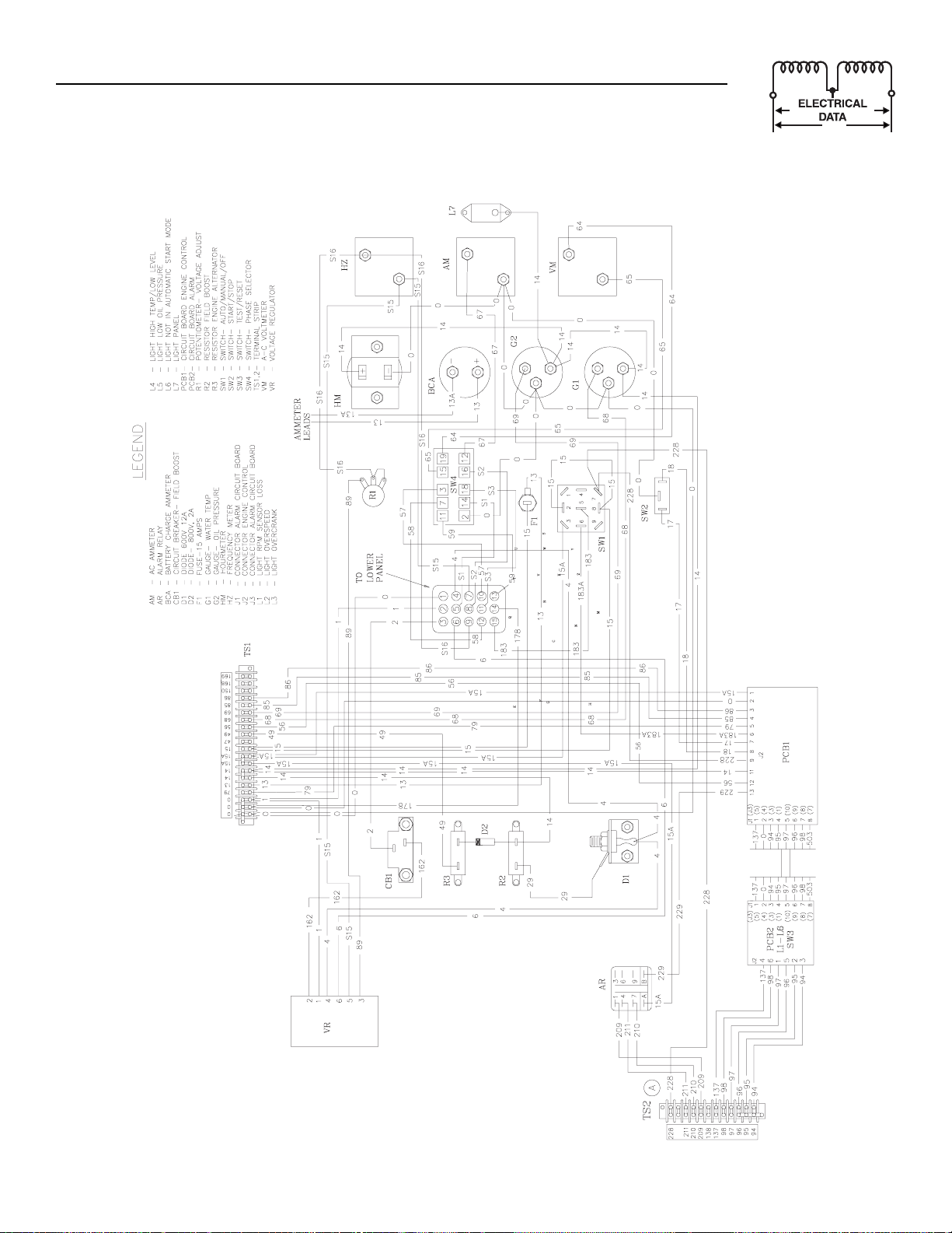
“C” Option Control Panel 12 Volt Gas
Control Panel Electrical Schematic – Drawing No. 85023-A
Page 17
Generac®Power Systems, Inc. 15
Appendix 1 — Electrical Data
“C” Option Control Panel 12 Volt Gas
Control Panel Wiring Diagram – Drawing No. 85024-A
Page 18

C
3
-
+
0
0
16 Generac®Power Systems, Inc.
Appendix 2 — Exploded Views and Parts Lists
“C” Option Control Panel 24 Volt Diesel
Control Panel – Drawing No. 84851-J
4
7
4
2
1
1
7
7
7
2
1
7
A
4
I
Page 19

Generac®Power Systems, Inc. 17
ITEM PART NO. QTY. DESCRIPTION
1 070023 1 CONTROL PANEL BOTTOM
2 070026 1 SLKSCRND PANEL FRONT
3 070028 1 COVER CON PNL SIDE
4 067680 1 ASSY VOLTAGE REGULATOR 60HZ
092952 1 ASSY VOLTAGE REGULATOR 50HZ
5 039271 1 FITTING 90 DEGREE 3/4
6 034616 1 FITTING STRAIGHT 3/4
7 1 CIRCUIT BREAKER
8 082985 1 RES 100R 5% 5W ASSY=55405
9 082984 1 RES 120R 10% 2W ASSY 55406
10 086266 1 RES WW LUG 75R 5% 25W
11 055444 1 HEATSINK
12 030468 1 WASHER STEP NYLON .20
13 049939 1 RECTIFIER MSC 12A 600V 1N1206R
14 083089 1 ASSY PCB "C" CONTROL 12/24V
15 033147 1 SCREW HHM #10-32 X 1
16 024469 2 SCREW HHTT #10-32 X 3/8 CZ_
17 084853A 1 HARNESS F/<100KW 24V C DIESEL
084853B 1 HARNESS F/>101KW 24V C DIESEL
084853C 1 HARNESS F/12LMITS 24V C DIESEL
18 029333 6 TIE WRAP 7.4"X.19" NATL UL
19 084875 1 DECAL TERMINAL STRIP
20 055920 1 SWITCH SPST SPADE PNL MNT
21 055867 1 SWITCH TOG SPDT 15A SPD MOM
22 067625 1 SWITCH TOGGLE 3P3T 15/10A
23 032300 1 HOLDER FUSE
24 022676 1 FUSE 15A X AGC15
25 040213 4 PCB SUPPORT SNAP-IN 1/4"
26 0C2428 14 SCREW PHTT #6-32 X 1/2 ZYC
27 061945 1 SWITCH SELECTOR 6A AMP/V
28 071361 1 POT 5K 10% 2.25W PNL
29 050123 1 KNOB PLASTIC .25 SHAFT
30 055349 1 INSULATOR
31 070030 1 COVER GENERAC SILKSCREENED
33 070042 1 FREQUENCY METER 240V 55-65HZ
070042-A 1 FREQUENCY METER 240V 45-55HZ
34 1 AC AMMETER
35 1 AC VOLTMETER
36 083287 1 LIGHT HLDR CLR LNS W/O BULB
ITEM PART NO. QTY. DESCRIPTION
37 070081 1 HOURMETER
38 062304 1 AMMETER 40-0-40 DC
39 055405 1 GAUGE OIL PRESSURE
40 055406 1 GAUGE COOLANT TEMPERATURE
41 070083 1 ASSY PCB ENGINE MONITOR
42 055089 1 CONN PLUG PNL 15P AMP M-N-L
43 070082 1 BLOCKER LIGHT
44 053247 1 LUG RNGTNG INS 22-18 X10 X.322
45 029187 2 SPACER .19 X .31 X .50 PL
46 077043B 1 FLEX CONDUIT .50 ID
50 036904 4 SCREW PPHM #6-32 X 3/4 (NOT SHOWN)
51 036908 2 SCREW PPHM #6-32 X 1-1/4
52 022155 2 WASHER LOCK #6
53 022985 6 WASHER FLAT #6 ZINC
54 022188 2 NUT HEX #6-32 STEEL
55 036918 4 SCREW PPHM #8-32 X 1/2
56 022264 4 WASHER LOCK #8-M4
57 033121 16 SCREW HHC #10-32 X ½
58 022152 26 WASHER LOCK #10
59 023897 14 WASHER FLAT #10 ZINC
60 022158 20 NUT HEX #10-32 STEEL
61 038150 4 WASHER FLAT #8 ZINC
62 022471 4 NUT HEX #8-32 STEEL
63 084787 1 CABLE RIBBON 16"
64 070370 2 WASHER MICA .203
65 083288 1 LIGHT 28VDC .17A MIN BAYNT MNT
66 023762 4 WASHER SHAKEPROOF EXT #10 STL
68 081767 2 RELAY PNL 24VDC DPDT 10A
70 064000 1 CONTROL PNL SIDE
71 064008 1 COVER CON PNL TOP
72 098940 1 HARNESS C-OPT CTRL PNL
73 066040 1 DECAL - TERM STRIP
77 0C2323 4 SCREW PHTT #6-32 X 5/8 ZYC
78 0C1229 1 DECAL CUST CONN BOX
79 022507 4 SCREW HHC 1/4-20 X 1/2 G5 (NOT
SHOWN)
80 022097 8 WASHER LOCK M6-1/4 (NOT SHOWN)
81 040479 4 VIB MNT 1.0 X 1.0 X 1/4-20 (NOT SHOWN)
Appendix 2 — Exploded Views and Parts Lists
“C” Option Control Panel 24 Volt Diesel
Control Panel – Drawing No. 84851-J
Page 20

18 Generac®Power Systems, Inc.
5
5
3
6
3
0
0
9
9
5
9
625
9
3
0
3
9
0
S
O
O
SS
S
.
G
G
8
6
3
O
+
-
)
CA
Appendix 2 — Exploded Views and Parts Lists
“C” Option Control Panel 24 Volt Gas
Control Panel – Drawing No. 84711-N
4
1
2
282
4
1
1
4
4
2
2
4
1
M
A
R
F
7
4
RAM #
F WIRE HARNE
N
DIA
TALLATI
EE WIRIN
IN
4
4
1
7
MI
2-PLCS
7
Page 21

Generac®Power Systems, Inc. 19
ITEM PART NO. QTY. DESCRIPTION
1 070023 1 CONTROL PANEL BOTTOM
2 070026 1 CONTROL PANEL FRONT
3 070028 1 CONTROL PANEL SIDE
4 067680 1 REGULATOR ASSEMBLY VOLTAGE B&D
5 039271 1 FITTING 90 DEGREE 3/4
6 034616 1 FITTING STRAIGHT 3/4
7 057159 1 CIRCT BRK 2 X 1 ETA 46-500-P
053623 1 CIRCT BRK 2.5 X 1 ETA 46-500-P
054502 1 CIRCT BRK 3 X 1 ETA 46-500-P
056247 1 CIRCT BRK 3.5 X 1 ETA 46-500-P
049350 1 CIRCT BRK 4 X 1 ETA 46-500-P
048476 1 CIRCT BRK 4.5 X 1 AUT30KW CNT45K
048512 1 CIRCT BRK 5 X 1 ETA 46-500-P
054450 1 CIRCT BRK 5.5 X 1 ETA 46-500-P
048505 1 CIRCT BRK 6 X 1 ETA 46-500-P
048467 1 CIRCT BRK 7 X 1 ETA 46-500-P
048468 1 CIRCT BRK 8 X 1 ETA 46-500-P
048470 1 CIRCT BRK 9 X 1 ETA 46-500-P
8 057335 1 BLOCK TERM 20A 20 X 6 X 1100V
9 046669 7 BLOCK TERM JUMPER FOR S141
10 ** 081767 1 RELAY PNL 24VDC DPDT 10A
11 070042 1 METER FREQUENCY 55-65HZ
070042A 1 METER FREQUENCY 240V 45-55HZ
12 070054 1 AMMETER AC 0 TO 50
070055 1 AMMETER AC 0 TO 100
070056 1 AMMETER AC 0 TO 150
070045 1 AMMETER AC 0 TO 200
070057 1 AMMETER AC 0 TO 300
070058 1 AMMETER AC 0 TO 400
070059 1 AMMETER AC 0 TO 600
070060 1 AMMETER AC 0 TO 800
13 070043 1 METER VOLT AC 0-300
070044 1 METER VOLT AC 0-600
14 083089 1 ASSY BOARD "C" CONTROL 12/24V
15 0C2428 8 SCREW TAPTITE PH #6-32 X 1/2 ZYC
17 064000 1 CONTROL PANEL SIDE
18 064008 1 COVER CONTROL PANEL TOP (NOT
SHOWN)
19 084736 1 DECAL TERMINAL STRIP
20 026536 1 PLUG STEEL 0.5
21 055867 1 SWITCH SPDT 15A SPD TGGL MOM
22 067625 1 SWITCH 3P TRIP THR 15/10A TGGL
23 032300 1 HOLDER FUSE
24 022676 1 FUSE 15A X AGC15
25 040213 4 PCB SUPPORT SNAP-IN 1/4
26 024469 2 SCREW TAPTITE #10-32 X 3/8 BP
27 061945 1 SWITCH 6A AMP/V SELECTOR
28 071361 1 POTENTIOMETER 5K +/-10% 2.25W PNL
29 050123 1 KNOB PLASTIC .25 SHAFT
30 055349 1 INSULATOR
31 070030 1 COVER GENERAC SILKSCREEN
ITEM PART NO. QTY. DESCRIPTION
32 * 084717 1 ASSEMBLY TIME RELAY
33 084733 1 HARNESS CONTROL PANEL C
34 083287 1 LIGHT HLDR CLR LNS W/O BULB
35 083288 1 LIGHT 28V DC .17A MIN BAYNT MNT
37 070081 1 METER HOURS
38 062304 1 AMMETER 40-0-40 DC
39 055405 1 GAUGE OIL PRESSURE
40 055406 1 GAUGE COOLANT TEMPERATURE
41 066040 1 DECAL TERMINAL STRIP
42 055089 1 CONN ELEC AMP M-N-L 15 PLUG PNL
43 070082 1 BLOCKER LIGHT
44 053247 1 LUG RNGTNG INS 22-18 X 10 X .322
45 029187 2 SPACER .19 X .31 X .50 ST/ZNC
46 077043B 16" FLEX CONDUIT .50 ID
47 029333 6 TIE WRAP 7" WHITE
49 0C2323 10 SCREW PHM SWAGE 6-32 X 5/8 Z/YC
50 036904 2 SCREW PPHM #6-32 X 3/4 (NOT SHOWN)
51 036908 2 SCREW PPHM #6-32 X 1-1/4
52 022155 2 WASHER LOCK #6
53 022985 6 WASHER FLAT #6-M4
54 022188 2 NUT HEX #6-32 STEEL
55 036918 4 SCREW PPHM #8-32 X 1/2
56 022264 11 WASHER LOCK M4
57 033121 14 SCREW HHM 10-32 X 1/2
58 022152 22 WASHER LOCK #10
59 023897 15 WASHER FLAT #10 ZINC
60 022158 11 NUT HEX #10-32 STEEL
61 038150 8 WASHER FLAT #8 ZINC
62 022471 4 NUT HEX #8-32 STEEL
63 084787 1 CABLE RIBBON 16"
64 070083 1 ASSEMBLY ENGINE MONITOR
65 082985 1 ASSEMBLY RESISTER 68 OHM 5W
66 082984 1 ASSEMBLY RESISTER 120 OHM 2W
67 098940 1 HARNESS C-OPT CTRL PNL
69 023762 3 WASHER SHAKEPROOF EXT #10 STL
70 055444 1 SINK HEAT
71 030468 1 WASHER STEP NYLON .20
72 049939 1 RECTIFIER MSC 12A 600V 1N1206R
73 070370 2 WASHER MICA .203
75 086266 1 RESISTOR WW LUG 75R 5% 25W
76 022507 4 SCREW HHC 1/4-20 X 1/2 G5 (NOT
SHOWN)
77 022097 8 WASHER LOCK M6-1/4 (NOT SHOWN)
78 040479 4 MOUNT VIBR 1.0 X 1.0 X 1/4-20 (NOT
SHOWN)
79 0441140156 1 WIRE ASSY 18AWG #0 (NOT SHOWN)
80 033147 1 SCREW HHM #10-32 X 1 (NOT SHOWN)
81 0C1299 1 DECAL WARNING
* USED ON 13.3L SPARK IGNITED ONLY
** USED ON 13.3L TURBO SPARK ONLY
Appendix 2 — Exploded Views and Parts Lists
“C” Option Control Panel 24 Volt Gas
Control Panel – Drawing No. 84711-N
Page 22

20 Generac®Power Systems, Inc.
Appendix 2 — Exploded Views and Parts Lists
“C” Option Control Panel 12 Volt Diesel
Control Panel – Drawing No. 85027-H
Page 23

Generac®Power Systems, Inc. 21
ITEM PART NO. QTY. DESCRIPTION
1 070023 1 CONTROL PANEL BOTTOM
2 070026 1 CONTROL PANEL FRONT
3 070028 1 CONTROL PANEL SIDE
4 067680 1 REGULATOR VOLT 60HZ
092952 1 REGULA TOR VOLT 50HZ
5 039271 1 FITTING 90 DEGREE 3/4
6 034616 1 FITTING STRAIGHT 3/4
7 057159 1 CIRCT BRK 2 X 1 ETA 46-500-P
053623 1 CIRCT BRK 2.5 X 1 ETA 46-500-P
054502 1 CIRCT BRK 3 X 1 ETA 46-500-P
056247 1 CIRCT BRK 3.5 X 1 ETA 46-500-P
049350 1 CIRCT BRK 4 X 1 ETA 46-500-P
048476 1 CIRCT BRK 4.5 X 1 AUT 30KW CNT45K
048512 1 CIRCT BRK 5 X 1 ETA 46-500-P
054450 1 CIRCT BRK 5.5 X 1 ETA 46-500-P
048505 1 CIRCT BRK 6 X 1 ETA 46-500-P
048467 1 CIRCT BRK 7 X 1 ETA 46-500-P
048468 1 CIRCT BRK 8 X 1 ETA 46-500-P
048470 1 CIRCT BRK 9 X 1 ETA 46-500-P
8 044213 1 RESIST MISC 10R X 12W
9 025192 1 RECTIFIER MSC 2A 600V 1N5062
10 048352 1 RESIST MISC 5R X 25W
057907 1 RESISTOR WW LUG 10R 10% 25W
057405 1 RESIST MISC 25R X 25W
11 055444 1 HEAT SINK 13.3L
12 030468 1 WASHER STEP NYLON .20
13 049939 1 RECTIFIER MSC 12A 600V 1N1206R
14 083089 1 BOARD "C" CONTROL 12/24V
15 024469 2 SCREW TAPTITE #10-32X3/8 BP
17 085058 1 HARNESS 12 VOLT DIESEL
18 029333 6 TIE WRAP 7" WHITE
19 070097 1 DECAL TERMINAL STRIP
20 055920 1 SWITCH 1PST PSADE PNL MNT
21 055867 1 SWITCH SPDT 15A SPD TGGL MOM
22 067625 1 SWITCH 3P TRIP THR 15/10A TGGL
23 032300 1 HOLDER FUSE
24 022676 1 FUSE 15A X AGC15
25 040213 4 CONN PCB SUP SNAP-IN
26 0C2428 8 SCREW TAPTITE PH #6-32 X 1/2 ZYC
27 061945 1 SWITCH 6A AMP/V SELECTOR
28 071361 1 POTENTIO PNL 5K +/-10% 2.25W
29 050123 1 KNOB PLASTIC .25 SHAFT
30 055349 1 INSULATOR
31 070030 1 COVER SILKSCREEN
32 070080 2 INSULATOR
33 070042 1 METER FREQUENCY 55-65HZ
070042A 1 METER FREQUENCY 240V 45-55HZ
34 070054 1 AMMETER AC 0 TO 50
070055 1 AMMETER AC 0 TO 100
070056 1 AMMETER AC 0 TO 150
070045 1 AMMETER AC 0 TO 200
ITEM PART NO. QTY. DESCRIPTION
070057 1 AMMETER AC 0 TO 300
070058 1 AMMETER AC 0 TO 400
070059 1 AMMETER AC 0 TO 600
070060 1 AMMETER AC 0 TO 800
35 070043 1 METER VOLT AC 0 TO 300
070044 1 METER VOLT AC 0 TO 600
36 070202 1 LIGHT PANEL
37 070081 1 METER HOURS
38 062304 1 AMMETER 40-0-40 DC
39 055405 1 GAUGE OIL PRESSURE
40 055406 1 GAUGE COOLANT TEMPERATURE
41 070083 1 ASSY ENGINE MONITOR
42 055089 1 CONN ELEC AMP M-N-L 15PLUG PNL
43 070082 1 BLOCKER LIGHT
44 053247 1 LUG RNGTNG INS 22-18 X 10 X .322
45 029187 2 SPACER .19 X .31 X .50 ST/ZNC
46 077043B 16" FLEX CONDUIT .50 ID
49 0C2323 12 SCREW PHM SWAGE 6-32X5/8 Z/YC
51 036908 2 SCREW PPHM #6-32 X 1-1/4
52 022155 2 WASHER LOCK #6
53 022985 2 WASHER FLAT #6
54 022188 2 NUT HEX #6-32 STEEL
55 036918 4 SCREW HHM #8-32 X 1/2
56 022264 6 WASHER LOCK M4
57 033121 14 SCREW HHM 10-32 X 1/2
58 022152 20 WASHER LOCK #10
59 023897 12 WASHER FLAT #10
60 022158 9 NUT HEX #10-32 STEEL
61 038150 4 WASHER FLAT #8 ZINC
62 022471 4 NUT HEX #8-32 STEEL
63 084787 1 CABLE RIBBON 16"
64 070370 2 WASHER MICA .203
65 063617 1 RELAY PNL 12VDC DPDT 10A @ 240VA
66 023762 1 WASHER SHAKEPROOF EXT #10 STL
67 057335 1 BLOCK TERM 20A 20 X 6 X 1100V
68 046669 5 JUMPER TERMINAL BLOCK
69 098940 1 HARNESS C-OPTION CONTROL PANEL
70 064000 1 SIDE CONTROL PANEL
71 064008 1 COVER CONTROL PANEL TOP
(NOT SHOWN)
72 066040 1 DECAL TERMINAL STRIP
73 022507 4 SCREW HHC 1/4-20 X 1/2 G5
(NOT SHOWN)
74 022097 8 WASHER LOCK M6-1/4 (NOT SHOWN)
75 040479 4 MOUNT VIBR 1.00X1.00X1/4-20
(NOT SHOWN)
76 036904 2 SCREW PPHM #6-32 X 3/4
(NOT SHOWN)
77 0441140156 1 ASSY WIRE 18AWG #15 (NOT SHOWN)
78 033147 1 SCREW HHM #10-32 X 1 (NOT SHOWN)
Appendix 2 — Exploded Views and Parts Lists
“C” Option Control Panel 12 Volt Diesel
Control Panel – Drawing No. 85027-H
Page 24

22 Generac®Power Systems, Inc.
3
9
5
9
9
0
8
9
3
9
0
5
5
3
6
0
6
9
G
G
850
OR
S
O
O
SS
S
.
)
CA
Appendix 2 — Exploded Views and Parts Lists
“C” Option Control Panel 12 Volt Gas
Control Panel – Drawing No. 085026-J
4
1
2
M
A
4
4
24 F
RAM #
F WIRE HARNE
N
DIA
TALLATI
EE WIRIN
IN
282
7
2
1
2
1
4
2
7
4
4
2
MI
2-PLCS
1
Page 25

Generac®Power Systems, Inc. 23
ITEM PART NO. QTY. DESCRIPTION
1 070023 1 PANEL BOTTOM CONTROL
2 070026 1 PANEL FRONT CONTROL
3 070028 1 PANEL SIDE CONTROL
4 067680 1 REGULATOR ASSY VOLTAGE 60HZ
092952 1 REGULATOR ASSY VOLTAGE 50HZ
5 039271 1 FITTING 90DEGREE ¾
6 034616 1 FITTING STRAIGHT ¾
7 057159 1 CIRCT BRK 2 X 1 ETA 46-500-P
053623 1 CIRCT BRK 2.5 X 1 ETA 46-500-P
054502 1 CIRCT BRK 3 X 1 ETA 46-500-P
056247 1 CIRCT BRK 3.5 X 1 ETA 46-500-P
049350 1 CIRCT BRK 4 X 1 ETA 46-500-P
048476 1 CIRCT BRK 4.5 X 1 AUT30KW CNT45K
048512 1 CIRCT BRK 5 X 1 ETA 46-500-P
054450 1 CIRCT BRK 5.5 X 1 ETA 46-500-P
048505 1 CIRCT BRK 6 X 1 ETA 46-500-P
048467 1 CIRCT BRK 7 X 1 ETA 46-500-P
048468 1 CIRCT BRK 8 X 1 ETA 46-500-P
048470 1 CIRCT BRK 9 X 1 ETA 46-500-P
8 044213 1 RESIST MISC 10RX12W
9 025192 1 RECTIFIER MSC 2A 600V 1N5062
10 044213 1 RESIST MISC 10RX12W
11 055444 1 HEAT SINK 13.3L
12 030468 1 WASHER STEP NYLON .20
13 049939 1 RECTIFIER MSC 12A 600V 1N1206R
14 083089 1 ASSY PCB "C" CONTROL 12/24V
15 024469 2 SCREW TAPTITE #10-32X3/8 BP
17 085025 1 HARNESS 12-V.GAS
18 029333 6 TIE WRAP 7" WHITE
19 070097 1 DECAL TERMINAL STRIP
20 026536 1 PLUG STEEL 0.5
21 055867 1 SWITCH SPDT 15A SPD TGGL MOM
22 067625 1 SWITCH 3P TRIP THR 15/10A TGGL
23 032300 1 FUSE HOLDER
24 022676 1 FUSE 15A X AGC15
25 040213 4 PCB SUPPORT SNAP-IN 1/4
26 0C2428 8 SCREW TAPTITE PH #6-32X1/2 ZYC
27 061945 1 SWITCH 6A AMP/V SELECTOR
28 071361 1 POTENTIO PNL 5K +/-10% 2.25W
29 050123 1 KNOB PLASTIC .25 SHAFT
30 055349 1 INSULATOR
31 070030 1 COVER GENERAC SILKSCREEN
32 070080 2 INSULATOR
33 070042 1 METER FREQUENCY 60HZ
070042A 1 METER FREQUENCY 50HZ
34 070054 1 AC AMMETER-0 TO 50
070055 1 AC AMMETER-0 TO 100
070056 1 AC AMMETER-0 TO 150
ITEM PART NO. QTY. DESCRIPTION
070045 1 AC AMMETER-0 TO 200
070057 1 AC AMMETER-0 TO 300
070058 1 AC AMMETER-0 TO 400
070059 1 AC AMMETER-0 TO 600
070060 1 AC AMMETER-0 TO 800
35 070043 1 AC VOLTMETER-0 TO 300
070044 1 AC VOLTMETER-0 TO 600
36 070202 1 LIGHT PANEL #26306C
37 070081 1 METER HOURS
38 062304 1 AMMETER 40-0-40 DC
39 055405 1 GAUGE OIL PRESSURE
40 055406 1 GAUGE COOLANT TEMPERATURE
41 070083 1 ASSY ENGINE MONITOR
42 055089 1 CONN ELEC AMP M-N-L 15PLUG PNL
43 070082 1 LIGHT BLOCKER
44 053247 1 LUG RNGTNG INS 22-18X10X.322
45 029187 2 SPACER .19X.31X.50 ST/ZNC
46 077043B 16" FLEX CONDUIT .50 ID
49 0C2323 12 SCREW PHM SWAGE 6-32X5/8 Z/YC
51 036908 1 SCREW PPHM #6-32 X 1-1/4
52 022155 2 WASHER LOCK #6
53 022985 2 WASHER FLAT #6
54 022188 2 NUT HEX #6-32 STEEL
55 036918 4 SCREW PPHM #8-32 X ½
56 022264 6 WASHER LOCK M4
57 033121 14 SCREW HHM 10-32 X ½
58 022152 22 WASHER LOCK #10
59 023897 14 WASHER FLAT #10 ZINC
60 022158 9 NUT HEX #10-32 STEEL
61 038150 4 WASHER FLAT #8 ZINC
62 022471 4 NUT HEX #8-32 STEEL
63 084787 1 CABLE RIBBON 16"
64 070370 2 WASHER MICA .203
65 063617 1 RELAY PNL 12VDC DPDT 10A@240VA
66 023762 1 WASHER SHAKEPROOF EXT #10 STL
67 057335 1 BLOCK TERM 20A 20 X 6 X 1100V
68 046669 5 BLOCK TERM JUMPER
69 098940 1 HARNESS "C" OPTION
70 064000 1 PANEL SIDE CONTROL
71 064008 1 PANEL TOP CONTROL (NOT SHOWN)
72 066040 1 DECAL TERMINAL STRIP
73 036904 2 SCREW PPHM #6-32 X 3/4 (NOT SHOWN)
74 022507 4 SCREW HHC 1/4-20 X 1/2 G5
75 040479 4 MOUNT VIBR 1.00X1.00X1/4-20
76 022097 8 WASHER LOCK M6-1/4
77 0441140156 1 ASSY WIRE 18AWG #0 (NOT SHOWN)
78 033147 1 SCREW HHM #10-32 X 1 (NOT SHOWN)
79 0C1299 1 DECAL WARNING
Appendix 2 — Exploded Views and Parts Lists
“C” Option Control Panel 12 Volt Gas
Control Panel – Drawing No. 085026-J
Page 26

24 Generac®Power Systems, Inc.
3
O
CO
O
L
U
L
5
O
R
O
D
S
S
S
CH
O
5
O
C
CO
C
ON
/
S
T
09
5A
9
U
Y
C
S
O
3
O
1
5
5
5
G
O
E
U
C
OR
5
5
5
83
8
4
0
87
G
O
OR
CU
O
D
O
M
5
5
5
506
505
500
50
50
506
500
50
505
37
5
5
5
8
9
5
9
5
5
O
S:
,
,
S
Q
K
C
G
O
S
S
G
S
S
M
S
O
O
O
O
S
S
S
S
S
G
S
O
G
O
CO
O
.
O
U
S
OU
3
CO
C
S
500
U
506
C
O
O
U
C
OR
O
8
35
O
S
O
O
C
O
O
U
S.
S
09
0
CO
C
Y
209 NC CONTACTS OPEN ON ANNUNCIATED SHUTDOWN
211 NO CONTACTS CLOSE ON ANNUNCIATED SHUTDOWN
210 C CONNECT TO FUSE +12V DC CIRCUIT AS SHOWN
8
9
0
O
COO
T
S
CH
O
O
SS.
GH
.
O
U
L
CH
G
E
U
K
3
Y
Y
3
,
.
CH
U
/
U
O/O
F
Appendix 3 — Interconnection Diagram
“C” Option Control Panel 12 Volt Gas
Interconnection Diagram – Drawing No. 87625
TE
Y
ET "A"
LAN
WIT
IN
EN
1
1
2
1
1
2
IL PRE
W
W
L
TEMP.
L
1
1
4
2
LANT TEMP
PREALARM HI
1
1
1
EL LEVE
W F
WIT
L
1
EL TAN
F
1
T
IAT
N
HT - REM
ANN
LI
1
2
22
1
2
1
1
1
1
LE BATTERY
IN
EE IN
N
LT
3-PHASE TRANSFER SWITCHE
UIPPED WITH NEUTRAL BLOC
ER WITH 12 V
THER VARIATI
R
HAR
1-PHASE & 4-POLE
WN. F
TE
H
N
1. 3-POLE
GENERALLY NOT E
2. 2 AMP
1
F
T
A
AL
WIT
MAN
L PANEL
NTR
R
ENERAT
N
HT
"D" & "E"
ET
EE IN
.
PREALARM LI
BATTERY ALAR
HI-L
NIT
N
PTI
"-
IAT
SEE INSET "G"
R "
N
T TP ALARM RELA
T WIRE
WN F
NNE
TE ANN
H
NNE
RN
-211
REM
-21
T TB
TLY T
2
ALARM H
2
WITH
DIRE
NIT
DEL
N
. M
TB2 TERMINAL
THR
CONTACTS. FOR "A" & "B" OPTION UNITS
L PANE
NTR
R
ENERAT
TE
N
NIT
INE M
EN
AR
IT B
IR
2
#7
22
1
2
ME
A
T
L
E
WIT
FER
TE
N
TRAN
T
TE
-N
T
XILIAR
A
NTA
1
PPL
TILIT
2
TB
17
1
TI
TRA
TAR
NNE
NE
2-WIRE
R A
E
PANEL W
ENERAT
Page 27

Generac®Power Systems, Inc. 25
Appendix 3 — Interconnection Diagram
“C” Option Control Panel 12 Volt Gas
Interconnection Diagram – Drawing No. 87625
G
COO
T
O
L
CK
CK
N
0
O
S
C
G
BLAC
WHITE
2
8
9
OS
T
G
WHITE
BLAC
S
50
O
S
S
S
S
CH
S
"
S
"
S
S
CH
S
600
O
S
S
U
CO
C
S
5
C
OS
ON
C
S
S
S
C
OS
O
C
ON
O
8
G
O
U
C
OR
O
U
R
Y
O
U
R
O
S
9555
9556
8
G
O
E
U
C
OR
S
S
C
OS
O
C
ON
O
8
G
O
U
C
OR
O
G
G
OU
D
)
O
Y
)
D
O
O
O
N
S
G"
O
S
CH
O
E
5
O
5
N
CK
9
5
5
9
O
CO
O
O
D
9
G
E
T
0
AM
P
/
F
G
R
C
Y
0
C
Y
S
0
C
G
/
C
G
S
S
S
1
PPE
R
T
IAT
12M
12AF
E
HAR
12VD
TANDB
TEM
Y
INE
HT - REM
DEL
LI
M
1
N
ANN
2
1
EN
LAN
IN
EN
2
2
BLA
REE
K
REEN
12 VD
ER W
HAR
VA
TILIT
A.
12
ET "A"-1
IN
NL
ENERAT
T
NTA
ERIE
WIT
FER
LT "N"
XILIARY
V
TRAN
T
TANDARD A
ITI
H P
WIT
T
NTA
4-64-
ATI
IAT
N
N INDI
ITI
TE ANN
H P
WIT
HT REM
LI
"N"
1
T
T
ET "E
IN
PPE
R
ENERAT
ATI
IAT
N
N INDI
ITI
TE ANN
H P
HT REM
WIT
LI
"Y"
1
T
T
ET "D
IN
R
N ALARM H
PTI
"A" & "B"
N
R
INE
EN
BATTER
BATTERY NEGATIVE
POSITIVE TERMINAL
T
T
LAN
INE
EN
TA
THERM
A
LT
V
2
1
ERIE
WIT
FER
LT "Y"
V
TRAN
2
T
12
BLA
NA
REE
BLA
PTI
K
REEN
AR
L B
NTR
T
WIT
RN
H
22
TE
N
BLACK/RE
D
DI
1
ET "
IN
Page 28

26 Generac®Power Systems, Inc.
3
O
CO
O
L
U
L
0
9
O
R
O
D
S
S
S
CH
O
5
O
C
CO
C
ON
/
S
T
09
0A
9
U
Y
C
S
O
3
U
L
O
1
0
0
0
G
O
E
U
C
OR
0
0
9
0
9
83
8
O
4
8
6
G
O
OR
CU
O
D
O
M
0
0
0
506
505
500
50
505
37
0
0
0
9
8
S
S
OR
9
5
9
9
5
5
O
COO
T
S
CH
O
O
SS.
GH
.
O
U
L
CH
G
E
U
K
3
3
Y
Y
3
0220
C
O
C
O
S:
,
,
S
Q
K
Q
T
C"
S
S
S
"
G
S
O
G
O
CO
O
.
O
U
S
OU
3
CO
C
S
500
U
506
C
O
O
U
C
OR
O
8
35
O
S
O
O
C
O
O
U
S
S
09
0
CO
C
O
209 NC CONTACTS OPEN ON ANNUNCIATED SHUTDOWN
211 NO CONTACTS CLOSE ON ANNUNCIATED SHUTDOWN
210 C CONNECT TO FUSE +24V DC CIRCUIT AS SHOWN
,
.
CH
U
/
U
O/O
F
Appendix 3 — Interconnection Diagram
“C” Option Control Panel 24 Volt Diesel
Interconnection Diagram – Drawing No. 87624
LAN
WIT
IN
EN
IL PRE
W
W
L
TEMP.
L
21
22
LANT TEMP
PREALARM HI
22
22
EL LEVE
W F
WIT
L
22
EL TAN
F
21
22
3-PHASE TRANSFER SWITCHE
UIRE 120 VAC FOR ENGINE COOLAN
UIPPED WITH NEUTRAL BLOC
"D" & "E
ET
1-PHASE & 4-POLE
TE
N
EE IN
.
2. 4.0L & 6.4L UNITS RE
1. 3-POLE
GENERALLY NOT E
"B" & "
.
NIT
N
PTI
L PANEL
"-
IAT
ALARM RELAY
SEE INSET "G"
NTR
R "
N
T T
R
T WIRE
WN F
NNE
TE ANN
H
NNE
ENERAT
RN
-211
REM
N
-21
T TB
TLY T
2
HT
ALARM H
2
WITH
DIRE
NIT
DEL
N
. M
CONTACTS. FOR "A" & "B" OPTION UNITS
TB2 TERMINAL
PREALARM LI
THR
NIT
INE M
EN
AR
IT B
IR
T
IAT
21
22
22
22
2
1
21
2
1
4
22
22
ME
1
A
2
T
L
N
TE
PPL
TILIT
-N
T
XILIAR
A
NTA
TRA
NE
N
HT - REM
ANN
LI
22
22
22
22
2
22
1
471
#
E
WIT
FER
TE
N
TRAN
T
22
N
N
NON
22
BATTERY ALAR
HI-L
L PANE
NTR
T
I
F
T
A
AL
MAN
WIT
R
ENERAT
TE
N
TE
RE
N
TB
17
1
TI
TRA
TAR
NNE
NE
2-WIRE
R A
E
PANEL W
ENERAT
Page 29

Generac®Power Systems, Inc. 27
Appendix 3 — Interconnection Diagram
“C” Option Control Panel 24 Volt Diesel
Interconnection Diagram – Drawing No. 87624
G
E
T
0
C
Y
G
E
T
O
L
R
3
S
"
0
/
F
G
R
3
3
G
S
O
Y
0
C
CK
N
0
6
R
Y
OU
D
O
R
8
G
WHITE
8
G
WHITE
OS
T
G
R
OS
T
G
C
OR
OS
T
BLAC
G
D
N
CK
CK
0
C
Y
3
3
G
S
O
Y
O
S
C
G
R
S
C"
0
3A
O
L
T
G
E
Y
0
C
R
G
E
0
6
3
3
G
S
O
U
L
G
R
8
8
OS
T
OS
T
G
R
OS
T
8
S
50
O
S
S
S
S
CH
S
"
O
S
9555
9556
8
G
O
E
S
S
C
OS
O
C
ON
O
8
G
O
U
C
OR
O
U
R
9
5
S
"
S
S
CH
S
600
O
S
S
Y
O
U
R
S
S
C
OS
O
C
ON
O
8
G
O
U
C
OR
9
5
S
S
OR
O
5
0
O
E
O
S
CH
S
G"
O
O
O
N
C
/
D
O
CO
O
O
D
9
PPE
R
PPER PANE
T
V A
TILIT
24
NL
RANKIN
CONTACTO
GROUN
BLA
BLA
REE
INE
2
1
LITER EN
.
1
TA
IN
21
21
21
LAN
EN
& THERM
NL
ENERAT
ERIE
LT "N"
V
T
WIT
FER
TRAN
ATI
IAT
N
N INDI
ITI
TE ANN
H P
WIT
HT REM
LI
"N"
1
T
T
ET "E
IN
NA
TA
TA
THERM
HEATE
IN
EN
REEN
LAN
TA
INE HEATE
EN
THERM
.4 LITE
-
4.
PTI
THERM
VA
E
INE
TILIT
12
HAR
LITER EN
LT
.
.4-1
-
V A
24
TILIT
2 AMP 24 V
ET "
IN
WITH 4.
T
-
HT - REM
DEL
LI
M
1
2
1
K
REEN
N
R
BLACKBLA
REE
NLY
INE
PPE
R
ENERAT
ERIE
LT "Y"
V
2
T
WIT
FER
TRAN
ATI
N INDI
ITI
H P
WIT
"Y"
T
IAT
N
TE ANN
HT REM
LI
1
T
ET "D
LITER EN
.
1
TA
IN
LAN
EN
& THERM
T
TE
I
N
WIT
E
VA
12
TILIT
24M
HAR
AMP 24AF
1
NA
NL
TA
PTI
HEATE
THERM
AR
L B
NTR
T
RN
H
RE
RE
K
BLA
REEN
ET "B
IN
22
D
DI
22
IN
R
N ALARM H
PTI
"A" & "B"
ET "
IN
IN
1
1
T
PPE
1
EN
T
NTA
RANKIN
21
21
INE HEATE
EN
Page 30

28 Generac®Power Systems, Inc.
Part II
Remote Annunciator
Panels
Page 31

Generac®Power Systems, Inc. 29
Section 1 — General Information
Remote Annunciator Panels
1.1 THREE LIGHT REMOTE
ANNUNCIATOR
The Generac Three Light Remote Annunciator
(Figure 1.1) provides a valuable reference when used
with the Generac automatic transfer switch and
standby generator with a C option control panel.
This equipment is designed to be mounted remotely
from the standby generator set. The panel, when
properly interconnected with a Generac standby generator system and transfer switch, annunciates up to
three (3) standby electric system operating parameters.
• Utility Power Supply: This light comes ON when
customer electric loads are being powered by the
NORMAL (utility) power source.
• Emergency Power Supply: This light comes ON
when customer electric loads are being powered by
the EMERGENCY (standby) power source.
• Generator Fault Light: This light comes ON when
the generator engine has shut down automatically
due to a fault condition (such as low oil pressure,
high coolant temperature, overcrank, overspeed,
or RPM sensor loss). Fault conditions that will
result in an automatic engine shutdown are discussed in the INSTRUCTIONS AND PARTS MANUAL for the applicable generator set.
Figure 1.1 — Model 8848 Annunciator Panel
Lights
1.1.1 INSTALLATION
Mount the annunciator at any convenient location
near or remote from the standby generator. Mounting
dimensions are shown in Appendix ???. Holes are
provided for fastening the panel to a desk, wall or
other convenient object. Four 7/8” (22mm) holes are
also provided for routing of required wiring into the
panel. Installation must comply with all applicable
codes and regulations.
Required wiring between the Model 8848 annunciator, the Generac generator meter and control (upper)
panel, and transfer switch auxiliary contacts are
shown in Appendix ???, Interconnection Diagram.
NOTE:
Two different types of auxiliary contacts may be
encountered on Generac transfer switches.
1.2 FIVE LIGHT REMOTE
ANNUNCIATOR
The Model 8617 Remote Annunciator Panel (Figure
1.2), when properly interconnected with a Generac
standby generator equipped with an Option C control
panel, will provide remote annunciation of the same
five engine operating parameters as the generator
panel. The remote panel mounts five advisory lamps.
On occurrence of one or more of the panel monitored
faults, the applicable lamp will illuminate and the
horn will sound. Both the lamp(s) and the Alarm
Horn can be turned OFF by depressing the Reset
switch. All five lamps may be tested by actuating the
Test switch. The following engine fault conditions will
be indicated on the annunciator panel:
• Low Engine Oil Pressure
• High Engine Coolant Temperature/Low Coolant
Level
• Overcrank Condition
• Overspeed Condition
• RPM Sensor Loss Condition
Figure 1.2 — Model 8617 Remote Annunciator
Page 32

30 Generac®Power Systems, Inc.
Section 1 — General Information
Remote Annunciator Panels
1.2.1 OPERATION
Both the remote and generator panel advisory lamps
are controlled by a single DC CONTROL-LATCHCRANK circuit board housed in the generator control
console. Engine mounted, normally open (N.O.)
switches and sensors provide the necessary signal to
the circuit board on occurrence of a monitored
engine fault. should any one (or more) of the monitored faults occur, an automatic engine shutdown,
illumination of the applicable lamp(s), and sounding
of the Alarm Horn will occur. circuit board action will
then “latch” the fault. That is, the applicable lamp(s)
will remain ON after engine shutdown. While any
lamp remains lighted (latched), further attempts at
generator cranking and startup are inhibited. A 12
volt DC input is required to operate the panel.
NOTE:
See applicable standby generator owner’s manual
for more detailed operational description of
remote and generator panel lamps.
1.2.2 CUSTOMER CONNECTIONS
Suitable, approved wiring must be purchased for
interconnection of the Remote Annunciator Panel
with Terminal block TB2. Connect each wire to a
numbered terminal block screw and to an identically
numbered terminal in the remote annunciator panel.
A total of nine wires are required. Numbered terminals may be identified as follows:
• #94 — Low Oil Pressure Shutdown
• #95 — High Coolant Temperature/Low Coolant
Level Shutdown
• #96 — Overcrank Shutdown
• #97 — Overspeed Shutdown
• #98 — RPM Sensor Loss Shutdown
• #137 — Test Switch Connections
• #138 — Reset Switch Connections
• #209 — Alarm Relay Normally Closed Contacts*
• #210 — Alarm Relay Common Contacts*
• #211 — Alarm Relay Normally Open Contacts*
* DO NOT EXCEED ONE (1) AMPERE OF CURRENT
ACROSS ALARM RELAY CONTACTS.
1.2.3 PARTS INCLUDED WITH REMOTE
PANEL
Factory shipment of any standby generator set which
includes the optional Remote Annunciator Panel will
include a WIRING HARNESS (Part No. 70287). The
WIRING HARNESS includes the following parts:
1. Terminal Block TB2 (Part No. 55911)
2. Terminal Block Decal (Part No. 66040)
3. Alarm Relay (Part No. 63617)
4. The Wiring Harness proper
1.3 18 LIGHT REMOTE ANNUNCIATOR
The Model 9555 Remote Annunciator Panel is a self
contained system, utilizing solid state circuits to
annunciate up to sixteen (16) engine-driven generator
operating parameters (Figure 1.3). The system meets
NFPA (National Fire Protection Association) specifications for standby electric power systems.
The system will monitor any sensing device having
normally-open (N.O.) contacts which provide a +DC
signal to the applicable panel lamp on contacts closure. On contacts closure, both an alarm lamp and
an alarm horn are activated and latched in to manual reset. The alarm horn may be silenced without disturbing the visual indication and with any subsequent alarm re-activating the horn. The system
includes a test circuit.
NOTE:
The one exception to the normally-open (N.O.)
contacts rule is the LOW BATTERY VOLTAGE
lamp. This lamp must be connected to normallyclosed (N.C.) contacts on the battery monitor circuit board, located in the generator control panel.
Figure 1.3 — Model 9555 Remote Annunciator
Panel
Page 33

Generac®Power Systems, Inc. 31
1.3.1 GENERATOR STOP SIGNALS
All signals occur when generator shutdown occurs as a
result of the failure indicated by the illuminated
lamp(s).
1. High Water Temperature/Low Water Level: This
lamp comes ON and the horn sounds when the generator’s high temperature alarm is active.
2. Low Oil Pressure: This lamp illuminates and the
alarm horn sounds when the generator’s low oil
pressure alarm is active.
3. Overspeed: This lamp turns ON and the alarm
horn sounds when the generator’s overspeed alarm
is active.
4. Overcrank: This lamp turns on and the alarm horn
sounds when the generator’s overcrank alarm is
active.
5. Sensor Loss: This lamp illuminates and the alarm
horn sounds when the generator’s rpm sensor loss
alarm is active.
1.3.2 LATCHABLE SIGNALS
The following signals can be individually selected by
means of miniature rocker switch on the Remote
Panel’s monitor circuit board. The available switch
positions are “Latch On” and “Latch Off”. “Latch Off ”
indicates the lamp will turn ON only when the signal is
present. “Latch On” indicates the lamp will be ON until
the monitor “Reset” switch is pressed. The alarm horn
sounds when “Latch” is selected. The horn will stay ON
until either the “Rearm Horn” or the “Reset” switch is
pressed.
1. Low Battery Voltage: This lamp illuminates when
the generator’s battery voltage drops low, indicating
a discharge condition.
2. High Battery Voltage: This lamp will turn ON when
generator battery voltage is high, indicating an overcharge condition.
3. Battery Charger Failure: This lamp will illuminate
on failure of the generator’s battery charge system.
4. Low Fuel: This lamp illuminates when an occur-
rence of a low fuel level in the generator’s fuel tank.
5. Pre-alarm/High Temp.: This lamp will illuminate
to warn of an approaching or imminent high coolant
temperature shutdown.
6. Pre-alarm/Low Temp.: This lamp will illuminate
when the coolant temperature has decreased, indicating an engine coolant heater failure.
7. Pre-alarm/Low Oil Pressure: This lamp will illuminate in advance of a low oil pressure shutdown. It
indicates engine oil pressure has decreased to near
the point of automatic shutdown.
8. Generator Run: This lamp illuminates to advise
that the generator has started and/or is running.
Lamp ON indicates the generator “run” circuit is
active (Wire #14 on units with 12 volts DC engine
control system, Wire #219 on units with 24 volts
DC engine control system).
1.3.3 OTHER LAMPS
1. System Ready: This lamp will be ON to indicate
the generator set is able to run. If the lamp is OUT,
a “stop” signal is present.
2. Not In Auto: This lamp will illuminate to indicate
the generator’s Auto-Off-Manual switch is NOT set
to “Auto” )that is, the switch is set to either “Manual”
or “Off” and automatic operation is not possible).
3. Horn Switch Off: This lamp will turn ON to indi-
cate the horn switch on the annunciator panel is
turned OFF. With the horn switch set to OFF, lamps
will not be affected. However, the alarm horn will
not sound.
4. Line Power: This lamp will be ON when the automatic transfer switch main contacts are in their
“Utility” position (and connected to the “Utility”
power supply).
5. Generator Power: This lamp will turn ON when the
transfer switch main contacts are in their “Standby”
position, i.e., load is connected to the generator
power supply.
1.3.4 PANEL WIRING INTERCONNECTIONS
All INPUT signal connections are made at a 24 screw
terminal block, located on the Remote Panel’s MONITOR CIRCUIT BOARD. Use purchased No. 14 AWG
wiring for all interconnections. Maximum recommended distance between the Remote Panel and the standby
generator should not exceed 1000 feet (305 meters). See
page 36 for installer’s wiring interconnections.
1.4 TROUBLESHOOTING
Troubleshooting the 18 lamp annunciator is limited to
checking wire connections at the generator panel, transfer switch and annunciator, and checking for proper DC
inputs to annunciator terminal strip. If all connections
and input DC voltage signals are good but a problem
still exists with the annunciator operation, replace
annunciator circuit board.
1. Automatic Generator Stop Signals: The horn and
lamp are always latched if one of these signals
occurs. Generator stop lamps and horn can be reset
by either the test/reset switch at the annunciator or
reset of fault lamps at the generator.
2. Test/Reset: Pressing the test/reset switch energizes
all lamps except the “horn switch off” lamp and the
horn. Release of the switch resets the lamps and
horn. The test/reset switch has no effect on fault
indicators at the genset.
Section 1 — General Information
Remote Annunciator Panels
Page 34

32 Generac®Power Systems, Inc.
Section 1 — General Information
Remote Annunciator Panels
3. Latch Select: The lamps and horn can be selected
to be latched by on-board switch. Unlatched signals
activate the lamp only; the lamp is de-energized if
the fault signal is cleared. Latching provides an
audible signal plus keeps the lamp energized as an
indicator even if the pre-alarm fault has been
cleared.
4. Rearm: The rearm clears the horn but not the
lamps. The lamps are held active by either latch or
fault signal. After rearm, horn is enabled to sound if
another fault occurs.
5. System Ready Lamp: This lamp indicates the
genset is operational. The lamp is energized whenever power is applied to the annunciator circuit and
no generator stop signals are present.
6. Line-Power/Gen Power Lamps: This indicates the
position of the transfer switch. When load is transferred to the genset, the “Generator Power” lamp is
lit and the horn sounds.
7. Horn Switch Off Lamp: This lamp indicates that
power to the horn has been disconnected by a horn
disable switch.
8. Annunciator Delays: Signals will be annunciated if
the exist for the following minimum times:
• Not in Auto, Horn Off, 100 seconds.
• Pre-alarm Low Oil Pressure, 10 seconds.
• All others, 1 second.
Signal Source Lamp Response Latched Rearm
High Temp. Control Board* Red Lamp & Hor n Yes Yes
Low Oil Control Board* Red Lamp & Horn Yes Yes
Overspeed Control board* Red Lamp & Hor n Yes Yes
Overcrank Control Board* Red Lamp & Horn Yes Yes
Sensor Loss Control Board* Red Lamp & Hor n Yes Yes
System Ready Annunciator Green Lamp No N/A
Line Power Transfer Switch Green Lamp No N/A
Generator Power Transfer Switch Yellow Lamp & Horn No Yes
High Battery Battery Monitor Yellow Lamp & Horn Select Yes
Low Battery Battery Monitor Yellow Lamp & HOrn Select Yes
Not In Auto Control Board Red Lamp & Horn No No
Horn Switch Off Annunciator Red Lamp No N/A
Signal Source Lamp Response Latched Rearm
Low Fuel Float Switch Yellow Lamp & Horn Select Yes
High Temperature Temperature Switch Yellow Lamp & Horn Select Yes
Low Temperature Temperature Switch Yellow Lamp & Hor n Select Yes
Low Oil Pressure Switch Yellow Lamp & Horn Select Yes
Generator Run Control Board Yellow Lamp & Horn Select Yes
Battery Charge Fail Battery Monitor Yellow Lamp & Horn Select Yes
1.5 ANNUNCIATED SIGNALS
1.6 PRE-ALARMS
Page 35

Generac®Power Systems, Inc. 33
Appendix 4 — Electrical Data
Three Light Remote Annunciator
Mounting Dimensions
Page 36

34 Generac®Power Systems, Inc.
Appendix 4 — Electrical Data
Five Light Remote Annunciator
Mounting Dimensions
Page 37

Generac®Power Systems, Inc. 35
Appendix 4 — Electrical Data
18 Light Remote Annunciator
Mounting Dimensions
Page 38

36 Generac®Power Systems, Inc.
Appendix 4 — Electrical Data
Three Light Remote Annunciator
Interconnection Diagram
Page 39

Generac®Power Systems, Inc. 37
Appendix 4 — Electrical Data
Five Light Remote Annunciator
Interconnection Diagram
Page 40

38 Generac®Power Systems, Inc.
Appendix 4 — Electrical Data
Five Light Remote Annunciator
Electrical Schematic – Drawing No. 066561
Leg
end
L1 = Low Oil Pressure Lamp
L2 = High Coolant Temperature Lamp
L3 = Overcrank Lamp
L4 = Overspeed Lamp
L5 = RPM Sensor Loss Lamp
SW1 = Reset Switch
SW2 = Test Switch
H1 = Alarm Horn
Page 41

Appendix 4 — Electrical Data
Three Light Remote Annunciator
Electrical Schematic – Drawing No. 067787
Generac®Power Systems, Inc. 39
Page 42

/
9
519
525
519
0
0
S
P
0
P
OR
9
0
ON
CO
L
P
CO
L
0
97
8
96
95
98
4
504
502
500
505
506
9
501
.
L
.
(
N
E
:
C
C
O
O
C
C
5/
OW
L
E
E
Y
OR
GH
CH
L
S
Y
CH
R
O
C
8
/
320191816151310
8
40 Generac®Power Systems, Inc.
Appendix 4 — Electrical Data
18 Light Remote Annunciator
Wiring Diagram – Drawing No. 086833-C
14
21
ANNUNCIAT
TERMINAL STRI
22
NOTE
BATTERY CHARGER FAILUR
POSITION 4) SHOWN DRIVE
2
BY LOW BATTERY SIGNAL
HIGH OR LOW BATTERY SIGNA
MAY BE USED
15/22
NTROL PANE
TERMINAL STRI
22
22
"C" OPTI
TRI
9
NTROL PANE
TRANSFE
N
N
WIT
AUXILIAR
NTACT
LOW FUE
WIT
22
15/22
14/21
HI
N
1
N
N
N
22
MONIT
EMBL
L
LOW TEMPERATUR
-
HIGH TEMPERATUR
-
LOW OI
-
21
14
Page 43

ITEM PART NO. QTY. DESCRIPTION
1 022442 4 NO.6-32 X 3/8” ROUND HEAD MACHINE SCREW
2 064009-A 1 LAMP - YELLOW
3 064009-B 1 LAMP - GREEN
4 067783 1 PANEL (SILKSCREENED)
5 056892 4 NO.10-24 X 3/8” CRIMPTITE SCREW
6 059143 1 FRONT PANEL
7 059144 1 PANEL SUPPORT BRACKET
8 022471 2 NO.8-32 HEX NUT
9 022264 2 NO.8 LOCK WASHER
10 059149 1 GENERAC DECAL
11 046357 1 TERMINAL BLOCK
12 036919 2 NO.8-32 X 5/8” PAN HEAD MACHINE SCREW
13 067784 1 TERMINAL BLOCK DECAL
14 059142 1 ENCLOSURE
15 064009 1 LAMP - RED
Appendix 5 — Exploded Views and Parts Lists
Three Light Remote Annunciator
Drawing No. 067786
Generac®Power Systems, Inc. 41
Page 44

ITEM PART NO. QTY. DESCRIPTION
1 066040 1 DECAL, TERMINAL BOARD
2 055911 1 BOARD , TERMINAL
3 063617 1 RELAY, ALARM
4 1 BOARD, TERMINAL & DECAL (OPTIONAL PRE-ALARM)
Appendix 5 — Exploded Views and Parts Lists
Five Light Remote Annunciator
Mounting Locations in Generator Control Console for Optional Terminal Boards and
Alarm Relay
42 Generac®Power Systems, Inc.
Page 45

ITEM PART NO. QTY. DESCRIPTION
1 066556 1 FRONT PANEL
2 066558 1 SUPPORT - TERMINAL STRIP
3 064012 1 MONITER PANEL - SILKSCREENED
4 059149 1 DECAL - GENERAC
5 064009 5 INDICATOR LIGHT (RED)
6 055920 2 PUSH BUTTON SWITCH
7 049441 4 #6-32 X 3/8” TAPTITE
8 061286 1 SOUND - ALERT
9 055911 1 TERMINAL STRIP
10 059150-A 1 DECAL
11 036919 2 #8-32 X 5/8” PPHMS
12 022264 2 #8 LOCK WASHER
13 022471 2 #8-32 HEX NUT
14 030957 2 RECEPTACLE LUG 1/4”
15 028799 5 RECEPTACLE LUG 1/4”
16 032012 14.5” #20 BARE COPPER WIRE
2
W
A
TO
4.0
28800
28799
6
6
A
28800
0
94
95
96
97
98
211
37
38
0
2
4
6349
Appendix 5 — Exploded Views and Parts Lists
Five Light Remote Annunciator
Panel Assembly - Drawing No. 066559-B
Generac®Power Systems, Inc. 43
EE
1
1
ETAIL 1 - USE HARNESS BOARD FROM
4 TO MAKE
ENGTH
IRE P/N
199-A
4
7
7
#1
#2
4312
ROM
144
1
1
1
2
144
.0"
.0"
.0"
.0"
.0"
.0"
12
.0"
12
.5"
4312
.0"
"
Page 46

ITEM PART NO. QTY. DESCRIPTION
1 098940 1 HARNESS
2 063617 1 RELAY
0
37209
0
0
Appendix 5 — Exploded Views and Parts Lists
Five Light Remote Annunciator
Harness (098940) - Drawing No. 070287-C
44 Generac®Power Systems, Inc.
7
1
21
1
7
4
1
Page 47

Generac®Power Systems, Inc. 45
ITEM PART NO. QTY. DESCRIPTION
1 055911 1 TERMINAL BLOCK VERNITRON #09012
2 071271 1 CONNECTOR 6-CKT AMP P/N 640250
3 028739 12 TIE WRAP 4”
2
0980-3
ON
G
37
09
0
0
09
37
0
2
9
5
31
00
56
5
06
62
.
OR
SC.
300V
569
W
S/30
G
T
1
T
E
G
T
0
8
9
5
6
3
OMTO
8
819.5
ON
8800
0
8
Appendix 5 — Exploded Views and Parts Lists
Five Light Remote Annunciator
Harness (C Option Control Panel) - Drawing No. 098940-C
LGTH
26.
26.
25.
25.1
1
2
21
22
24.7
24.
7.
.
.1
WIRE DE
L 1007/1
#18 AWG
16 STRAND
DK BLUE COL
TE
AW
LUG #
ETC# AA-2190-06XINSULATED SNAPSPAD
#6 SCREW 18-22 AW
OR EQUIVALEN
LUG #
AMP# 35
OR EQUIVALEN
INSULATED FAST
.187 X .020" #18-22 AW
.25" PIGGYBACK FAST
ENERAC P/N - 02
FR
A
A
A
A
A
A
A1
7
4
7
2
1
2
21
1
22
1
Page 48

ITEM PART NO. QTY. DESCRIPTION
1 086582 1 PANEL, ANNUNCIATOR REAR
2 084968 1 PC BOARD - MONITOR
3 086579 1 SUPPORT, PC BOARD
4 040213 6 PCB STAND OFF
5 086580 2 SUPPORT, PC BOARD
6 036901 6 #6-32 X 3/8” PHCS
7 086581 1 PANEL, ANNUNCIATOR FRONT
8 061282-A 1 DECAL, CLEAR LEXAN
9 061283 1 SWITCH, ON/OFF
10 061284 2 SWITCH, TEST/RESET
11 032300 1 HOLDER, FUSE
12 044299 1 FUSE, 1 AMP
13 061286 1 SOUNALERT
14 077704 1 PLUG
15 086584 1 DECAL, ATTENTION
ITEM PART NO. QTY. DESCRIPTION
16 056892 4 CRIMPTITE
17 025034 2 PLUG BUTTON
18 086583 2 DECAL, ANNUNCIATOR
29* 028739 2 TIE WRAP
30†¥ 048766 1 TERM BLOCK
31†¥ 055869 1 SWITCH - TOGGLE, SPST
32 022985 6 #6 FLAT WASHER
33 022155 6 #6 LOCK WASHER
34 022188 6 #6-32 HEX NUT
* NOT SHOWN
SERIES
† 86585B — 86583 DECAL
¥ 86585M — 86583M DECAL
23
222
20
46 Generac®Power Systems, Inc.
Appendix 5 — Exploded Views and Parts Lists
18 Light Remote Annunciator
Drawing No. 086585$-C
2
1
7
4
#17
1
#19
#18
#23
#22
#21
#20
Page 49

Appendix 6 — Notes
Five Light Remote Annunciator
Generac®Power Systems, Inc. 47
Page 50

48 Generac®Power Systems, Inc.
Appendix 6 — Notes
Five Light Remote Annunciator
Page 51

Generac®Power Systems, Inc. 49
Appendix 6 — Notes
Five Light Remote Annunciator
Page 52

Part No. 0C4205
GENERAC®POWER SYSTEMS, INC.
P.O. BOX 8
WAUKESHA, WI 53187
Revision B (09/27/02) Printed in U.S.A.
 Loading...