

Page 1

OWNER'S MANUAL
IM-72
AIR-COOLED
Manual No. A2624
INDUSTRIAL MOBILE
GENERATORS
Model No. 00843-0
POWER SYSTEMS. INC.
Revision 0 (9/29/98)
Printed in U.S.A.
Page 2

EMISSION CONTROL SYSTEM WARRANTY
Emission Control System Warranty ("ECS Warranty") for 1995 and Later Model Year Utility and Lawn and Garden Equipment
Engines;
A. Applicability: This warranty shall apply to 1995 and later model year utility and lawn and garden equipment engines. The
ECS Warranty Period (“ECS Warranty Period”) shall begin on the date the new engine or equipment is delivered to its origi
nal, end-use purchaser and shall continue for 24 consecutive months thereafter.
B. General Emissions Warranty Coverage: Generac Corporation warrants to the original, end-use purchaser of the new engine
or equipment and to each subsequent purchaser that each of its utility and lawn and garden equipment engines is:
1. Designed, built and equipped so as to conform with all applicable regulations adopted by the Air Resources Board pur
suant to its authority, and
2. Free from defects in materials and workmanship which, at any time during the ECS Warranty Period, will cause a warrant
ed emissions - related part to fail to be identical in all material respects to the part as described in the engine manufac
turer's application for certification.
C. The ECS Warranty only pertains to emissions-related parts on your engine, as follows:
1. Any warranted, emissions-related parts which are not scheduled for replacement as required maintenance in the Owner's
Manual shall be warranted for the ECS Warranty Period. If any such part fails during the ECS Warranty Period, it shall be
repaired or replaced by Generac Corporation according to Subsection (4) below. Any such part repaired or replaced under
the ECS Warranty shall be warranted for any remainder of the ECS Warranty Period.
2. Any warranted, emissions-related part which is scheduled only for regular inspection as specified in the Owner's Manual
shall be warranted for the ECS Warranty Period. A statement in such written instructions to the effect of “repair or
replace as necessary" shall not reduce the ECS Warranty Period. Any such part repaired or replaced under the ECS
Warranty shall be warranted for any remainder of the ECS Warranty Period.
3. Any warranted, emissions-related part which is scheduled for replacement as required maintenance in the Owner's
Manual shall be warranted for the period of time prior to first scheduled replacement point for that part. If the part fails
prior to the first scheduled replacement, the part shall be repaired or replaced by Generac Corporation according to
Subsection (4) below. Any such emissions-related part repaired or replaced under the ECS Warranty shall be warranted
for the remainder of the ECS Warranty Period prior to the first scheduled replacement point for such emissions-related
part.
4. Repair or Replacement of any warranted, emissions-related part under this ECS Warranty shall be performed at no charge
to the owner at a Generac Corporation Authorized Service Outlet.
5. The owner shall not be charged for diagnostic labor which leads to the determination that a part covered by the ECS
Warranty is in fact defective, provided that such diagnostic work is performed at a Generac Corporation Authorized
Service Outlet.
6. Generac Corporation shall be liable for damages to other original engine components or approved modifications proximately caused by a failure under warranty of any emission-related part covered by the ECS Warranty.
7. Throughout the ECS Warranty Period, Generac shall maintain a supply of warranted emission-related parts sufficient to
meet the expected demand for such emission-related parts.
8. Any Generac Corporation authorized and approved emission-related replacement part may be used in the performance
of any ECS warranty maintenance or repairs and will be provided without charge to the owner. Such use shall not reduce
Generac Corporation ECS warranty obligations.
9. Unapproved add-on modified parts may not be used to modify or repair a Generac Corporation engine. Such use voids
this ECS Warranty and shall be sufficient grounds for disallowing an ECS Warranty claim. Generac Corporation shall not
be liable hereunder for failures of any warranted parts of a Generac Corporation engine caused by the use of such an
unapproved add-on or modified part.
EMISSION RELATED PARTS INCLUDE THE FOLLOWING:
1. Carburetor assembly and its internal components.
a. Fuel filter
b. Carburetor gaskets
c. Fuel pump (if so equipped)
2. Air cleaner assembly
a. Air filter element
b. Intake pipe/manifold
3. Ignition system including:
a. Spark plug
b. Ignition module
4. Catalytic muffler (if so equipped)
a. Muffler gasket (if so equipped)
b. Exhaust manifold (if so equipped)
5. Crankcase breather assembly and its components,
a. Breather connection tube
Page 3
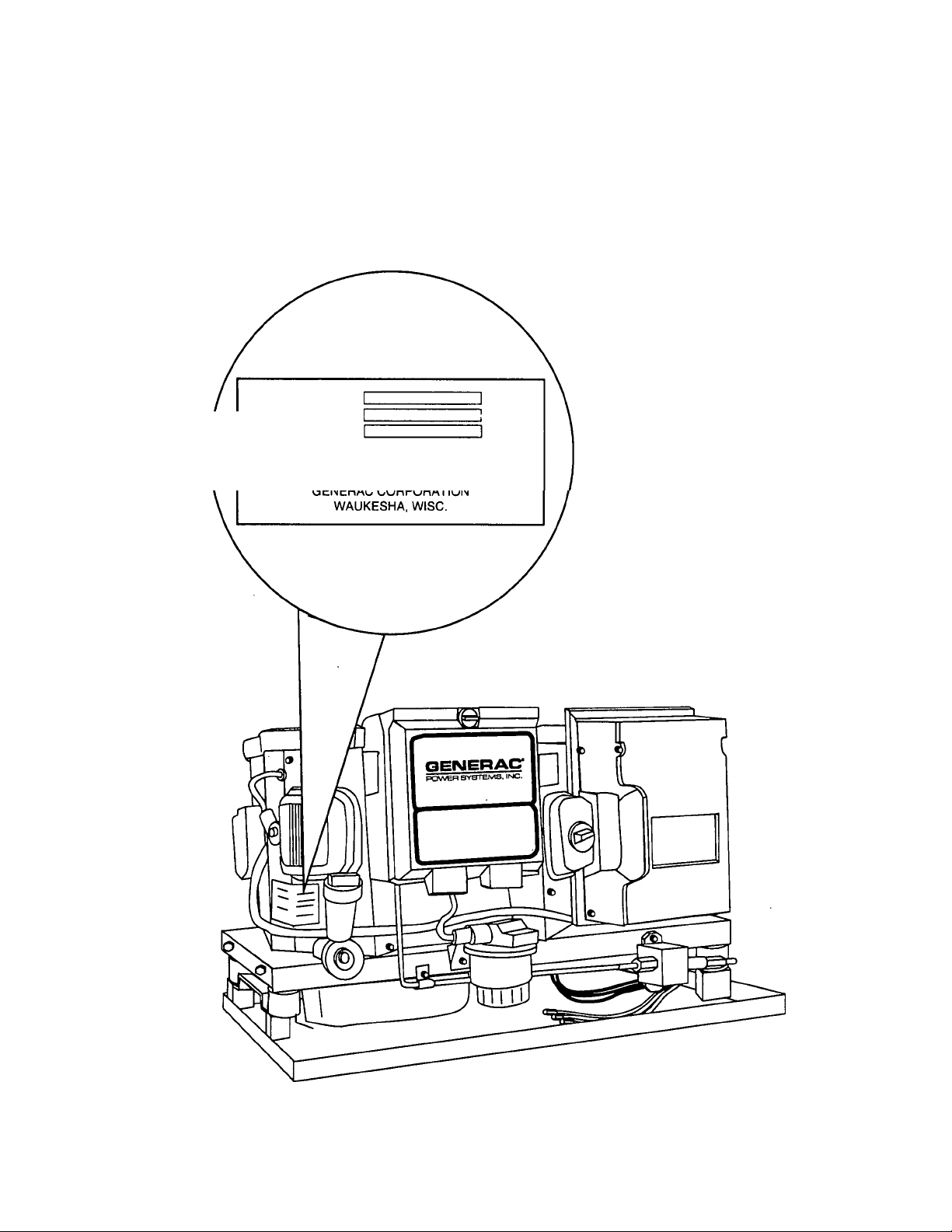
IDENTIFICATION RECORD
Please record the following information from the generator DATA PLATE or information decal.
1. Model Number______________________ 2. Serial Number___________________________
3.kW Rating.
5. Phase
_____
GENERATOR RPM
MODEL NO.
SERIAL NO.
FOR SERVICE CENTER LOCATION CALL
800-333-1322 24 HOURS A DAY
4. Rated Voltage.
6. Hertz
________
— 3 —
Page 4

TABLE OF CONTENTS
GENERAL SAFETY RULES
......
inside cover
IDENTIFICATION RECORD.................... 3
READ THIS MANUAL THOROUGHLY
Operation and Maintenance
How to Obtain Service.................................................. 5
.........................................
GENERATOR FAMILIARIZATION
Generator Applicability
Installation.....................................................................6
Safety........................................................................... 6
Generator AC Connection System
.................................................
...............................
OPERATING INSTRUCTIONS
Operating Precautions.................................................. 7
Generator Control Panel
Fuel Primer....................................................................7
Start/Stop Switch...........................................................7
Fuse..............................................................................7
Main Breaker.................................................................7
Remote Start/Stop Switch
Automatic Choke
Before Starting the Engine
Installation.....................................................................8
Engine Lubrication
Fuel Supply
Cooling and Ventilation Air
Engine Exhaust Gas
Starting the Generator.................................................. 8
Stopping the Generator
25 Hour Break-In Period................................................8
25 Hour Check-up Period..............................................9
Attention Required After Submersion
Effects of Moisture and Dirt...........................................9
Automatic Low Oil Pressure Shutdown
High Oil Temperature Shutdown
Field Boost
Over Voltage Protection
Engine Governed Speed.............................................10
Drive Belt.....................................................................10
Fuel Requirements......................................................10
Optional LP Gas Fuel System
...................................................................
..................................................................
..............................................
.............................................
..........................................................
...........................................
........................................................
............................................
.....................................................
................................................
............................
.........................
...................................
................................................
.....................................
9
10
SPECIFICATIONS
Engine Oil Requirements........................................11
Engine Specifications
Generator Specifications
5
6
6
7
7
7
7
MAINTENANCE
Checking Engine Oil Level
Change Engine Oil
Change oil filter
Engine Air Cleaner
Clean Air Intake Screen
Engine Spark Plugs
Fuel Filter
Spark Arrestor Muffler
Cleaning the Generator...........................................13
Battery............................................................... 13-14
Major Service Manual
Drive Belt.................................................................14
Exercising the Generator
Out of Service Protection
Return the Unit to Service after Storage
................................................................
TROUBLESHOOTING............................15
ELECTRICAL DATA
8
8
8
8
8
9
9
9
9
REPAIR PARTS
CAL. EMISSIONS WARRANTY
WARRANTY
.............................................
........................................
.....................................
.................................................
.......................................................
..................................................
..........................................
...........................................
.............................................
.............................................
........................................
........................................
.................
..............................
................................
17-25
.........
...................................
back page
11
11
11
11
12
12
12
12-13
13
13
14
14
14
14
16
26 - 27
Page 5

READ THIS MANUAL THOROUGHLY
If you don't understand any portion of this manual,
contact Generac for a demonstration of actual start
ing, operating and servicing procedures.
Throughout this publication and on tags and decals
affixed to the generator, DANGER and CAUTION
blocks are used to alert you to special instruction
about a particular operation that may be hazardous if
performed incorrectly or carelessly. Observe them
carefully.
These safety warnings cannot eliminate the hazards
that they indicate. Strict compliance with the special
instructions while performing the service plus "com
mon sense" are major measures to prevent acci
dents.
The following definitions apply to DANGER, WARN
ING, CAUTION and NOTE blocks found throughout
the manual.
DANGER: Indicates an immediately hazardous sit
uation which, if not avoided, will result in death or
A
serious injury. Danger is limited to the most
extreme situations.
WARNING: Indicates a potentially hazardous situ
ation which, if not avoided, could result in death or
serious injury.
CAUTION: Indicates a potentially hazardous situa
tion which, if not avoided, may result in minor or
moderate injury. Caution may also be used to alert
against unsafe practices.
NOTE: After this heading you can read explanatory
statements that require special emphasis.
These symbols indicate the following:
Points out important safety information and, if
not followed, could endanger personal safety
and/or property of yourself and others.
A
OPERATION AND MAINTENANCE
It is the operator's responsibility to perform all safety
checks: to make sure that all maintenance for safe
operation is performed promptly; and to have the
equipment checked by an Authorized Dealer periodi
cally. Normal maintenance service and replacement
of parts are the responsibility of the Owner/Operator
and, as such, are not considered defects in materials
or workmanship within the terms of the warranty.
Individual operating habits and usage contribute to
the need for maintenance service.
Proper maintenance and care of your industrial
mobile generator assures a minimum number of prob
lems and keeps your operating expenses at a mini
mum. See your authorized Dealer/Distributor for ser
vice aids and accessories.
HOW TO OBTAIN SERVICE
When your industrial mobile generator set requires
servicing or repairs, simply contact an Authorized
Service Facility for assistance. Service technicians
are factory-trained and are capable of handling all of
your service needs.
When contacting an Authorized Service Facility or the
factory about parts and service, always supply the
complete model number and serial number of your
unit as given on its data decal.
The warranty on your generator is included in this
Owner's Manual, as well as listings for repair parts.
SERVICE DEALER LOCATION
To locate the nearest Generac Servicing Dealer,
please call our 800 number.
Only dealer location information can be obtained
at this number.
Potential explosion hazard.
Potential fire hazard.
Potential electrical shock hazard.
A
1 -800-333-1322
WARNING:
The engine exhaust from this product
contains chemicals known to the State of
California to cause cancer, birth defects,
______
or other reproductive harm.
________
Page 6
GENERATOR FAMILIARIZATION
GENERATOR APPLICABILITY
These generators have been designed and manufac
tured for supplying electrical power for industrial mobile
vehicles. You should not modify the generator or use it
for any application other than for what it was designed.
If there are questions pertaining to its application, write
or call the factory. Do not use the unit until you have
been advised by a competent authority.
DANGER: For fire safety, the generator must have
been properly installed in compliance with industry
standards. The generator also must have been
installed in strict compliance with the manufactur
er’s detailed installation instructions. After installa
tion, do nothing that might render the unit in noncompliance with such codes, standards and
instructions.
CAUTION: Do not overload the generator. Some
installations may require that electrical loads be
alternated to avoid overloading. Applying exces
sively high electrical loads may damage the genera
tor and may shorten its life. Add up the rated watts
of all electrical lighting, appliance, tool and motor
loads the generator will power at one time. This
total should not be greater than the wattage capaci
ty of the generator. If an electrical device name
plate gives only volts and amps, multiply volts
times amps to obtain watts (volts x amps = watts).
Some electric motors require more watts of power
(or amps of current) for starting than for continuous
operation.
SAFETY
Before using the generator set, carefully read GENER
AL SAFETY RULES inside the cover. Comply with
these RULES to prevent accidents and damage to
equipment and/or property. Generac suggests copying
and posting the GENERAL SAFETY RULES in poten
tial hazard areas of the generator. Safety should be
stressed to all operators of this equipment.
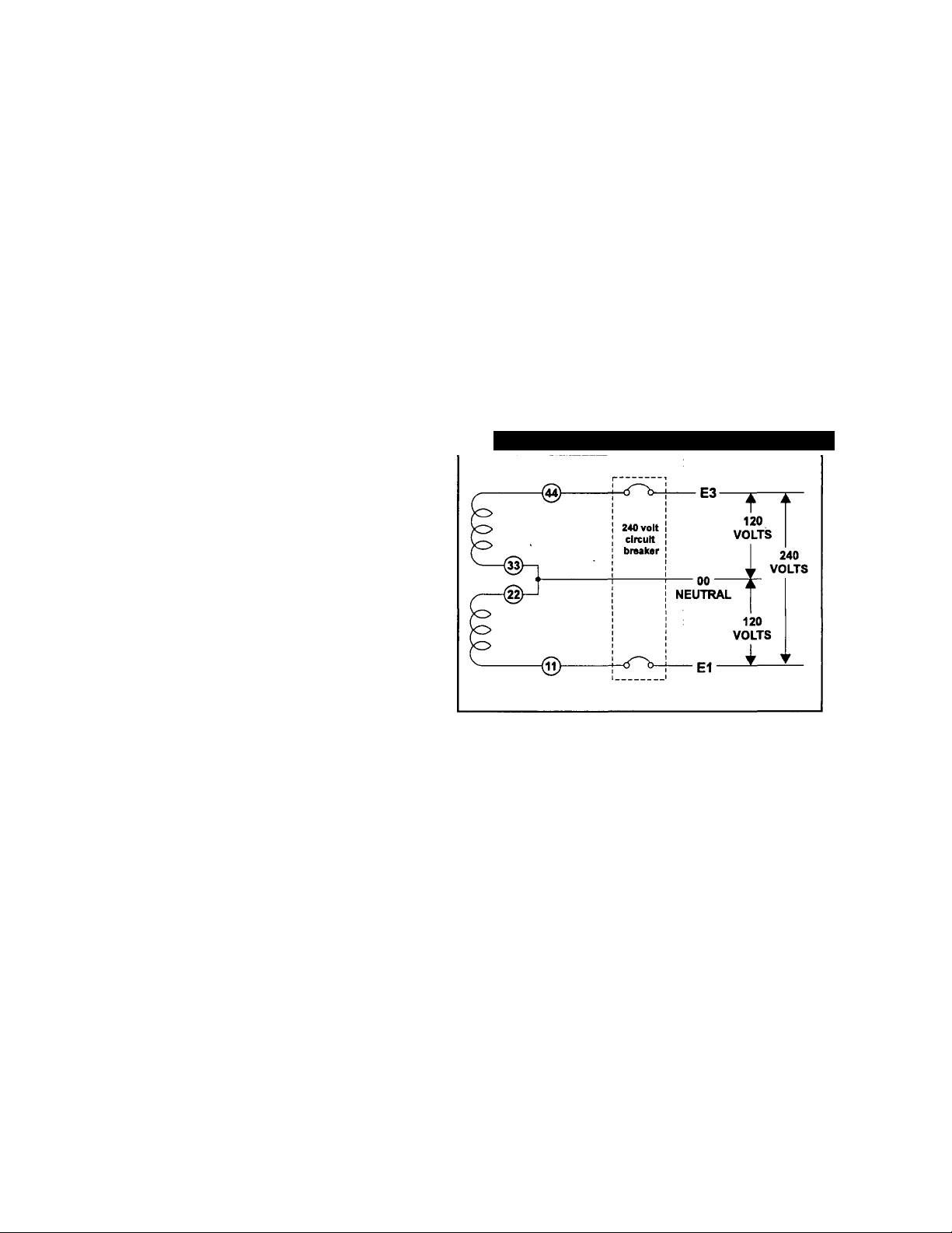
GENERATOR AC CONNEaiON
SYSTEM
This generator is equipped with with a 3-phase, Y con
nected stator. The unit is capable of delivering 3phase and 1-phase voltage simultaneously. It is
extremely important that any single phase load is
applied to the correct winding, since this winding has
been designed to accept 1-phase load. The maximum
1 -phase load that can be applied is 3.0 kW.
Figure 1 — Connections for 1-Phase and 3-Phase
INSTALLATION
This Owner’s Manual has been prepared under the
assumption that a competent, qualified technician
installed the generator into an industrial vehicle. We
also assume the installer complied with all applicable
codes, standards and regulations pertaining to installa
tion.
Owners/Operators should make sure nothing is done
during installation that might render the unit unsafe or
in noncompliance with applicable codes, standards
and instructions. They should be sure the unit has
been installed to allow adequate ventilation for cooling
and exhaust air.
— 6 —
Page 7
OPERATING INSTRUCTIONS
OPERATING PRECAUTIONS
WARNING: Never operate the generator set while
the vehicle is parked over dry leaves, dry grass or
any other combustible substance. The generators
exhaust system becomes extremely hot and can
cause fire if it is too close to combustible materials.
WARNING: The generators exhaust system gives
off deadiy carbon monoxide gas. This dangerous
gas, if breathed in sufficient concentrations can
cause unconsciousness and even death. Never
operate the generator set with the vehicle inside any
garage or other enclosed area. Never operate the
generator with a leaking exhaust system. Close
windows in the vicinity of the generator exhaust
outlet and take any other steps that may be neces
sary to prevent exhaust gases from entering areas
occupied by people.
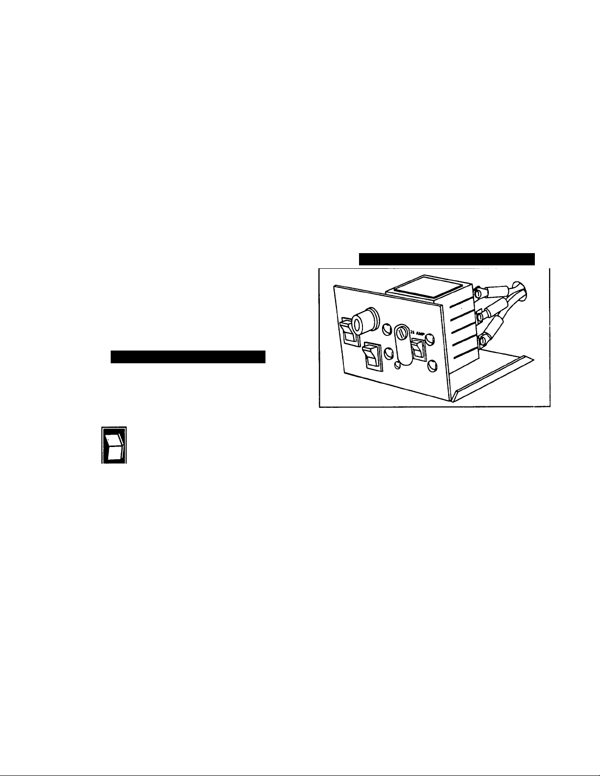
GENERATOR CONTROL PANEL
Mounted on the generator control panel (Figure 3) are
the following features;
Figure 3 — Generator Control Panel
FUSE
Protects the engine DC control circuit against electrical
overload. If the fuse element has melted open due to
overloading, the engine cannot be cranked. If you must
replace it, use only an identical replacement fuse.
MAIN BREAKER
Protects generators AC output circuit against overload
and provides a method of turning OFF the generators
120/208 volts AC output to vehicle circuits. This unit is
fitted with a 25A 3-pole circuit breaker (Figure 4).
NOTE: Refer to THE GENERATOR AC CONNEC
TION SYSTEM on page 4. Individual installations may
differ. If an overload occurs, the breaker will open the
stator leads.
Figure 4 — 25 Amp-Dual Circuit Breaker
o
MAIN BREAKER
START SWrrCH
STOP SWITCH
----------
TV
FUEL PRIMER
Before starting r. cold engine (it has not been started in
more than two weeks), you must press this switch to
bring fuel from the tank to the carburetor. This rocker
type switch springs back into its original position when
you release it.
m START/STOP SWITCH
To crank and start the engine, hold this switch at its
START position. Release the switch when the engine
starts. To stop an operating engine, press and hold the
switch in its STOP position until the engine shuts off.
The switch center position is the RUN position.
©
FUSE
PRIMER
8b
0
0
-TX
REMOTE START/STOP PANEL
A remote mounted Start/Stop Panel is available, which
allows you to start and stop the generator engine con
veniently from inside the vehicle.
AUTOMATIC CHOKE
The engine is equipped with an automatic choke.
During engine cranking (Start/Stop switch at START),
a solid state choke module signals the choke solenoid
to acuate a cyclic rate dependent on ambient tempera
ture. The choke solenoid thus opens and closes the
carburetor choke valve only when the engine is crank
ing. When you start it and release the start/stop
switch, choke action stops. As the engine warms, the
carburetor choke valve then opens gradually.
BEFORE STARTING THE ENGINE
IMPORTANT: INSTRUCTIONS AND INFORMATION
IN THIS MANUAL ASSUME THE GENERATOR HAS
BEEN PROPERLY INSTALLED, CONNECTED, SER
VICED, TESTED AND ADJUSTED BY A OUALIFIED
INSTALLATION TECHNICIAN OR INSTALLATION
CONTRACTOR. .
-7-
Page 8

INSTALLATION
Generator installation must have been properly com
pleted so it complies with all applicable codes, stan
dards and regulations and with the manufacturer's rec
ommendations.
ENGINE LUBRICATION
Have engine crankcase properly serviced with recom
mended oil before starting. Refer to "Maintenance" and
"Specifications" sections for oil servicing procedures
and recommendations.
CAUTION: Any attempt to crank or start the engine
before you have properly serviced it with the recom
mended oii may resuit in engine failure.
STARTING THE GENERATOR
To start the generator from either the generator control
panel or from the optional Remote Panel, proceed as
follows:
1. Turn OFF electrical loads, using whatever means provided
in your vehicle (such as a main line circuit breaker or
transfer switch.
NOTE; If starting from the generator panel, turn OFF
loads by setting the generators main circuit breaker to
“OFF” or “OPEN”. If starting from a Remote Panel,
turn OFF loads using whatever means is provided in
the vehicle (such as a main circuit breaker).
2. If the engine is warm, skip step 2. If you have not started
the engine in more that two weeks, press the Fuel Pump
Primer switch and hold it for about 30 seconds.
FUEL SUPPLY
The engine must have adequate supply of proper fuel
to operate. Before starting, check that sufficient fuel is
available.
NOTE: On some installations, the generator may have
been provided with its own fuel tank. On other installa
tions, the generator may “share” with the vehicle’s fuel
tank. When the vehicle’s tank is shared, some
installers may have installed a generator fuel pick up
tube in the shared tank that is shorter than the vehi
cle's pick up tube. When a shorter generator fuel pick
up tube is installed in the tank, the generator will run
out of gas while sufficient fuel remains in the tank for
vehicle engine operation.
■ COOLING AND VENTILATING AIR
Air inlet and outlet openings in the generator compart
ment must be open and unobstructed for continued
proper operation. Without sufficient cooling and venti
lating air flow, the engine-generator quickly overheats,
which causes it to quickly shutdown. Overheating
could also damage the unit or your vehicle.
ENGINE EXHAUST GAS
Before starting the generator engine, you should be
sure there is no way for exhaust gases to enter the
vehicle interior and endangering people. Close win
dows, doors and other openings in the vehicle that, if
open, might permit exhaust gases to enter the vehicle.
DANGER: The generator engine gives off deadly
carbon monoxide gas through its exhaust system.
This dangerous gas, if breathed in sufficient con
centrations, can cause unconsciousness or even
death. Do not operate the generator if its exhaust
system is leaking or has been damaged. Symptoms
of carbon monoxide poisoning are (a) inability to
think coherently, (b) vomiting, (c) twitching mus-
cies, (d) throbbing tempies, (e) dizziness, (f)
headache, (g) weakness and sleepiness. If you feel
any of these symptoms, move into fresh air immedi
ately. If symptoms persist, get medical help.
3. To crank and start the engine, hold the start/stop switch at
START. Release the switch when the engine starts.
CAUTION; If the engine does not start after it has
been cranking for 15 seconds, release the start/stop
switch and try again. Holding the switch for longer
than 15 seconds can damage the starter motor.
4. Let the engine run at no-load for a few minutes to stabilize
and warm up the engine.
5. Turn ON electrical loads, using whatever means provided
(such as a main circuit breaker or transfer switch).
STOPPING THE GENERATOR
1. Turn OFF all electrical loads, using whatever means pro
vided (such a main circuit breaker or transfer switch).
2. Place Start/stop switch in its STOP position.
25 HOUR BREAK-IN PERIOD
The first 25 hours of operation is the break-in period for
the generator. Properly breaking in the generator is
essential to reducing oil consumption and enhancing
engine performance. During the break-in period,
observe the following rules:
• For the first 25 hours, run the gerierator at varying electri
cal loads, to help set the engine piston rings properly.
• Following the initial 25 hour break-in period, avoid light
electrical loads for the next 75 hours of operation. The unit
should be loaded at 50% (or more) of its capacity during
those 75 hours. Repeated light loads during break-in peri
od may improperly seat the piston rings, resulting in blowby and high oil consumption.
• Check oil level frequently during the break-in period. Add
oil if needed. It is natural for the generator engine to con
sume, more oil than is normal until the piston rings have
seated properly.
• When the 25 hour break-in period is done, complete the
tasks recommended under 25 HOUR CHECK-UP PERIOD.
— 8 —
Page 9
25 HOUR CHECK-UP PERtOD
After the first 25 hours of operation have been com
pleted, contact an Authorized Service Facility for the
following maintenance. The Owner/Operator is
responsible for any changes.
• Change engine crankcase oil and oil filter.
• Check all cooling system ventilation openings.
• Check engine carburetor adjustments.
• Check engine ignition system.
• Inspect the entire electrical system.
• Inspect the engine exhaust system.
AHENTION REQUIRED AFTER
HIGH TEMPERATURE
SHUTDOWN
A temperature switch (Figure 5) with normally-open
(N.O.) contacts is mounted on the engine. Should
engine temperature exceed about 284°F (140°C), the
switch contacts close and the engine shuts down.
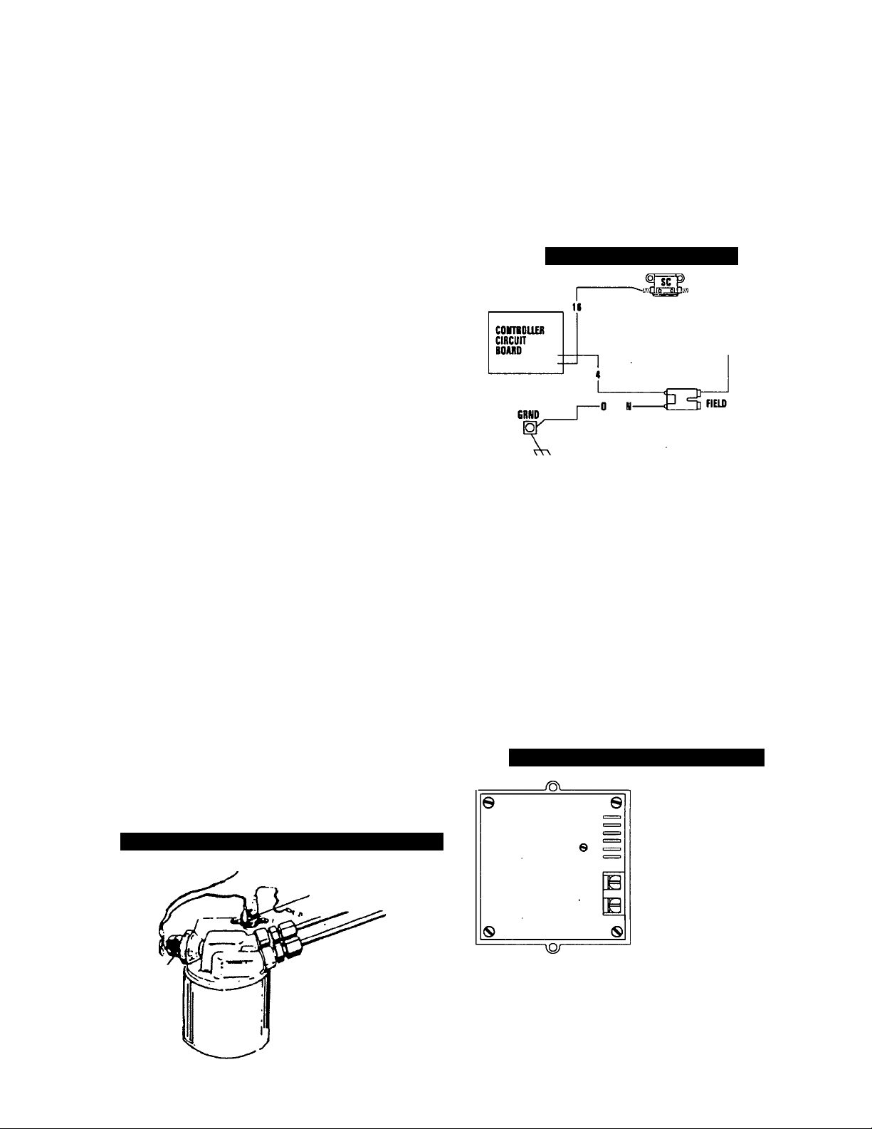
FIELD BOOST
The controller Circuit Board houses a field boost diode
and resistor. These two components are part of a
“field boost" circuit (Figure 6).
Figure 6 — Field Boost Circuit
SUBMERSION
If the generator has been submerged in water, it must
NOT be started or operated. Following any submersion
in water, have an authorized Generac Service Facility
thoroughly clean and dry the generator.
EFFECTS OF MOISTURE AND DIRT
Keep the generator set as clean and dry as possible.
Protect unit against excessive dust, dirt, corrosive
vapors, road splash, etc. Permitting dirt and moisture
to accumulate on generator windings will have an
adverse effect on the insulation resistance of those
windings.
When moisture is allowed to remain in contact with
windings, some of the moisture will be retained in voids
and cracks in the insulation. This causes a reduced
insulation resistance and will eventually cause prob
lems. Dirt will make the problem worse, since dirt tends
to hold moisture in contact with windings. Salt (as from
sea air) will also worsen the problem since it tends to
absorb moisture from the air. Salt and moisture, when
combined, form a good electrical conductor.
AUTOMATIC LOW OIL PRESSURE
SHUTDOWN
The engine is equipped with a normally-closed (N.C.)
oil pressure switch (Figure 5). Engine oil pressure
holds the switch open during cranking and operation.
Should oil pressure drop below about 8-10 psi, the
switch contact? close and the engine automatically
shuts down.
Figure 5 — Oil Pressure and Temperature Switches
High
Temperature
Switch
CLOSEST TO
BEARING
During engine cranking only, a positive DC (battery)
voltage is delivered through the diode, resistor, brush
es and slip rings, and to the generator rotor.
Application of this voltage to the rotor ‘Hashes the field"
whenever it is started. Flashing of the field each time
the generator starts makes sure that a sufficiently
strong magnetic field is available to produce the
required “pick up” voltage in the stator windings.
OVER VOLTAGE PROTECTION
A solid state voltage regulator (Figure 7) controls the
generators AC output voltage. This regulator supplies
an excitation current to the rotor. By regulating the
rotor’s excitation current, the strength of its magnetic
field is regulated and, in turn, the voltage delivered to
connected electrical loads is controlled. When the AC
frequency is 60 Hz, voltage is regulated at 208 volts, 3phase.
Figure 7 — Solid State Voltage Regulator
-SENStNO
-4<*Hj_TOROTOW
(DRECT CURRENT)
FROM STATOR
EXCITATION WWDtNO
(ALIERNATINO CURREKT]
Oii
Pressure
Switch
The voltage regulator also incorporates a “voltage
surge protection circuit.” This circuit prevents trouble
some surges in the generator AC output voltage.
Voltage surge is a common cause of damage to elec
tronic equipment.
— 9 —
Page 10
ENGINE GOVERNED SPEED
The generator is equipped with a 2-pole revolving field
(rotor) which must be driven at 3600 rpm to produce
the unit’s rated AC frequency of 60 Hz. The gas
engine governor was factory set to about 62 Hz. (3000
RPM) at no-load. After installing it, the technician
should check and adjust the governed speed. Setting
no-load frequency slightly high helps prevent exces
sive frequency, rpm and voltage droop under heavy
electrical loading.
DRIVE BELT
The engine drives the generator rotor by means of a
pulley and drive belt arrangement. The drive belt and
pulleys are warranted for the life of the generator.
Drive belt tension was properly adjusted before the unit
was shipped from the factory. If you suspect that drive
belt tension is incorrect, contact an authorized service
facility.
DANGER: Do not tamper with the engine governor
settings. Excessively high engine speeds are dan
gerous and increase the risk of personal injury and
damage to equipment and/or property. Excessively
low speeds impose a heavy load on the engine
when adequate engine power is not available and
may shorten engine life. The generator supplies
correct rated frequency and voltage only at the
proper speed. Some electrical devices may be dam
aged by incorrect frequency and/or voltage. If
engine speed appears to be incorrect, contact your
nearest authorized service facility.
FUEL REQUIREMENTS
These generators are equipped with gasoline fuel sys
tems as standard equipment. Specific installations
may provide either a separate fuel tank for the genera
tor, or the generator may “share” the vehicle engine’s
fuel tank.
NOTE: Installations using a “shared” fuel tank may
have a generator fuel pickup tube that is shorter than
the vehicle engine’s pickup tube. Such an arrange
ment causes the generator engine to “run out of gas”
while adequate fuel for the vehicle remains in the tank.
To reduce lead and carbon deposits use high quality
UNLEADED gasoline with the generator. Leaded
REGULAR grade gasoline is an acceptable substitute.
CAUTION: Generac does not recommend using any
gasoline containing alcohol (such as “gasohol”). If
you use any gasoline containing alcohol, it must not
contain more than 10 percent ethanol and it must be
removed from the tank during storage. Do NOT use
any gasoline containing methanol. If you use gaso
line with alcohol, inspect more frequently for fuel
leaks and other abnormalities.
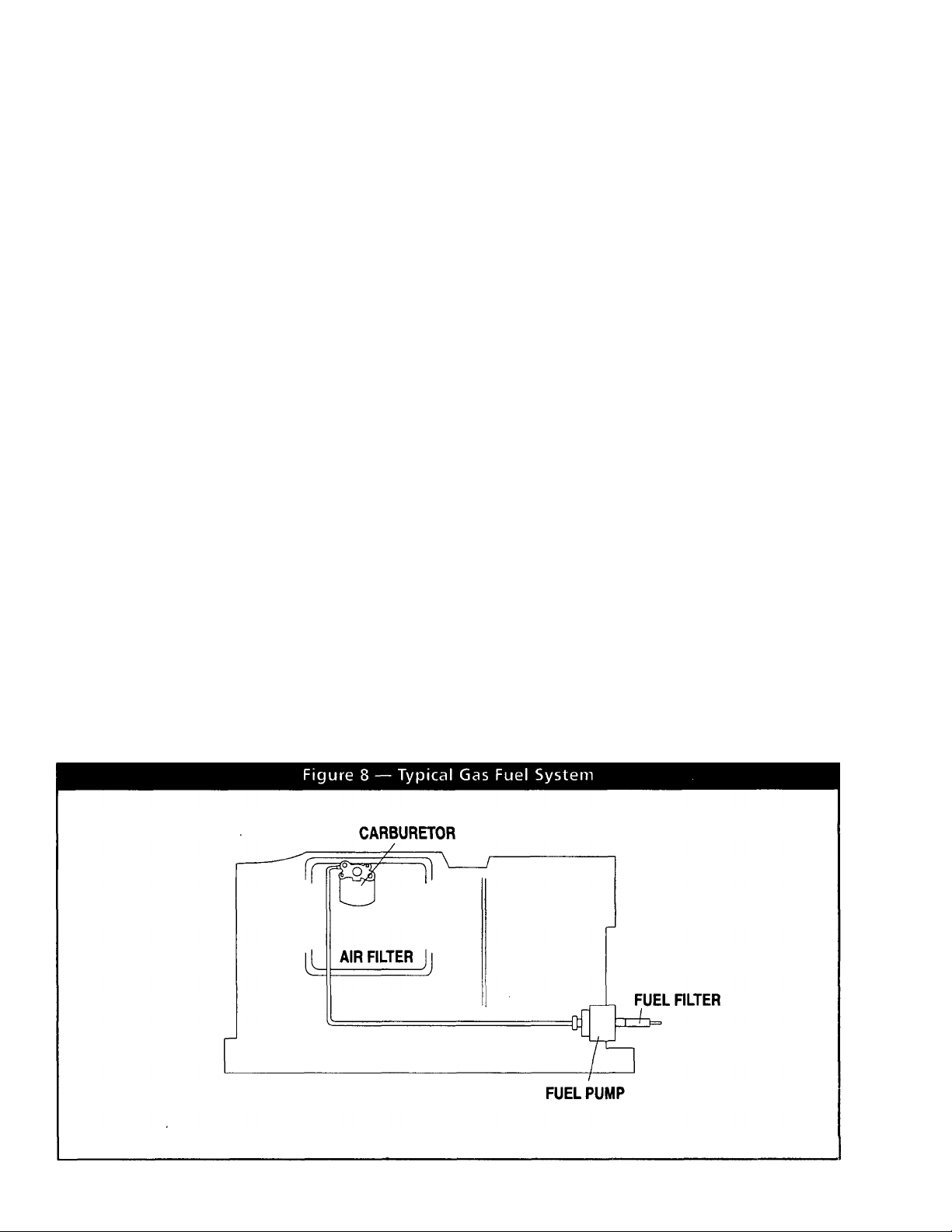
OPTIONAL LP GAS FUEL SYSTEM
This generator may be equipped with an optional liquid
propane (LP) gas fuel system. LP gas is usually sup
plied as a liquid in pressure tanks (Figure 8).
The IM series generators require a “vapor withdrawal”
type fuel system. This type of gaseous fuel system
uses the vapors forming above the liquid fuel in the
storage tank. Air temperatures around the storage
tank must be high enough to sustain adequate fuel
vaporization. In colder climates, you may need to use
an independent heat source to be sure the fuel suffi
ciently vaporizes in the storage tank.
LP gas may consist of propane, butane, or a mixture of
the two gases. Propane vaporizes at temperatures as
low as -20°F (-29°C), but butane returns to its liquid
state when the temperature drops below about 32°F
(0°C). For that reason, a higher ratio of propane is
desired in the gas mixture when temperatures drop
below freezing.
— 10 —
Page 11
SPECIFICATIONS
MAINTENANCE
ENGINE OIL REQUIREMENTS
Use a high quality detergent oil classified “For Service
SF and with an oil viscosity rating of SAE 10W-30 oil.
Do not pour in any additives to the recommended oil.
Engine crankcase capacity is 1.5 U.S. quarts. See
MAINTENANCE section for oil level check and filling
procedures.
TEMPERATURE OIL GRADE (recommended)
Above 60°F (16°C) SAE30
20“ to 59“F(-7“ to15“C) SAE 10W-30
Below 20“F (-7“C1
All Seasons
SAE5W-20or5W-30
SAE 5W-30 Synthetic Oil
GENERATOR SPECIFICATIONS
Series...................................................................IM-72G
Rotor RPM
Rotor Poles
Engine RPM.............................................................2900
Wattage*...................................................................7200
Voltage*
Current*.....................................................§25/20 AC ampst
Phase.............................................................................1
Frequency..............................................................60 Hertz
Weight................................................................200 pounds
Length
Width...........................................................................18.5 inches
Height.............................................................................16 inches
t Rated maximum continuous current at 120 volts 1-phase
between LI and 00 ONLY (S.OkW).
§ Rated maximum continuous current at 208V 3-phase
(7.2kW).'
...............................................................
....................................................................
............................................................
............................................................................
3600
120/208V
This section includes information about simple mainte
nance which includes the following tasks:
• Checking engine oil level.
• Changing engine oil.
• Changing oil filter.
• Engine air cleaner service.
• Cleaning the air intake screen.
• Cleaning spark plugs.
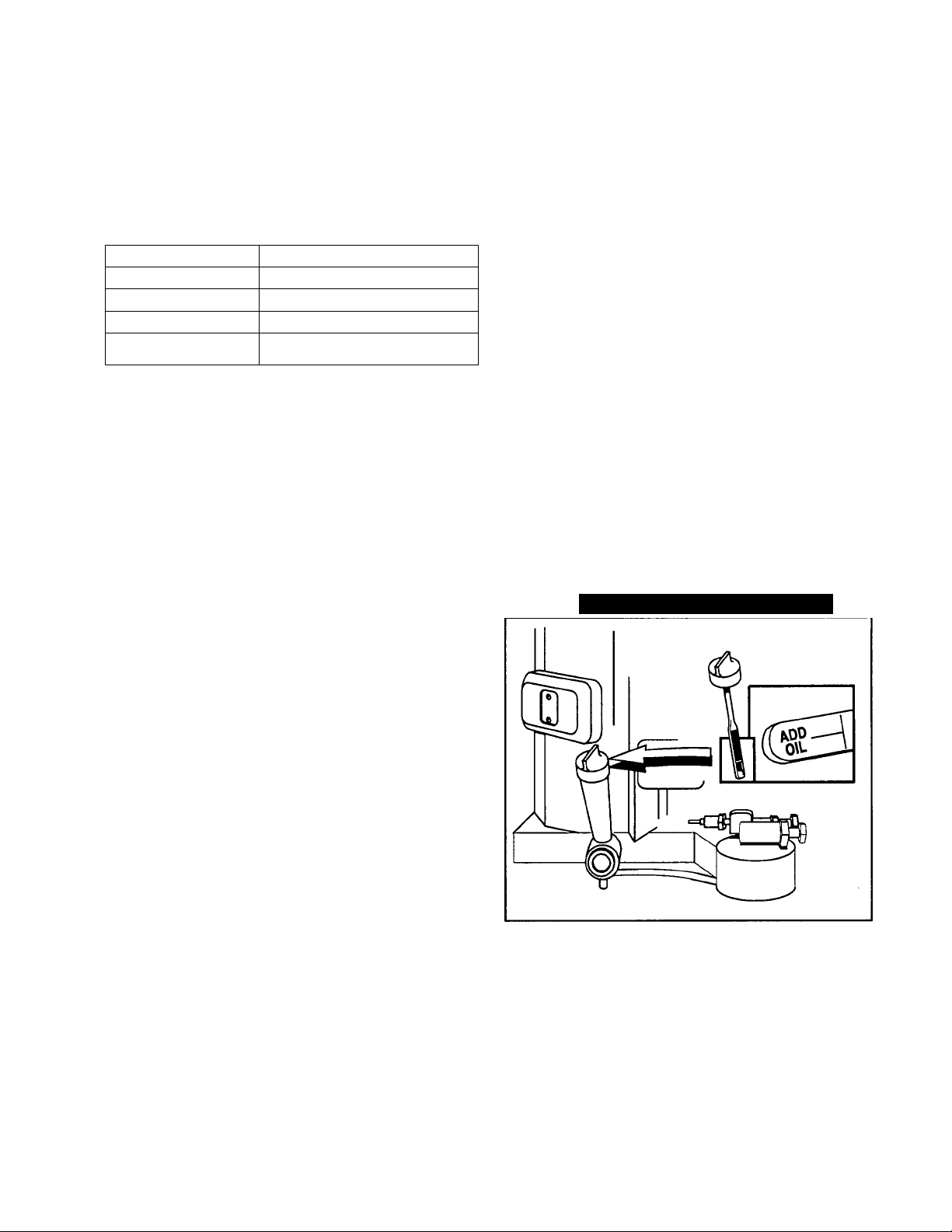
Check engine crankcase oil level at least every eight
hours of operation, or before each use (Figure 9).
• Be sure the generator is as level as possible.
• Remove oil dipstick and wipe dry with clean, lint-free cloth.
• Install and tighten oil dipstick, then remove again.
• Oil should be at dipstick FULL mark. If necessary, add the
2
• Install and tighten oil dipstick cap before operating the
25 inches
CHECKING ENGINE OIL LEVEL
recommended oil to the FULL mark only. DO NOT FILL
ABOVE “FULL” MARK.
engine.
NOTE: See “Engine Oil Requirements” on Page 9 for
recommended oils.
Figure 9 — Oil Dipstick and Fill Tube
ENGINE SPECIFICATIONS
Type of Engine............................................................Twin Cylinder
Cooling Method................................................Air-cooled
Rated Horsepower
Displacement..........................................................570cc
Compression Ratio
Cylinder Block...................................Aluminum with cast
........................................................................iron sleeve
Type of Governor
Engine Governed Speed
Air Cleaner
...............................................................foam pre-cleaner
Starter
Ignition System........................................Solid state with
..............................................................flywheel magneto
Recommended Spark Plugs
Spark Plug Gap
........................................
.................................................
..................................
................................................
......................
..............................
Mechanical, fixed speed
.........................................
Paper element with
12 volt DC electric
............
Champion RC12YC
0.030 inch (0.76mm)
19 at 3600 rpm
8.6 tol
2900
Change engine oil .after the first 25 hours of operation
(after the 25 hour break-in period, Page 6). Thereafter,
change oil every 100 operating hours. Change oil more
frequently if operating consistently under heavy load or
at high ambient temperatures.
• Warm up engine for at least five minutes, then shut down.
• With engine still warm from running, remove cap from oil
— 11 —
CHANGE ENGINE OIL
drain hose (Figure 10). Drain oil completely into a suitable
container.
Page 12
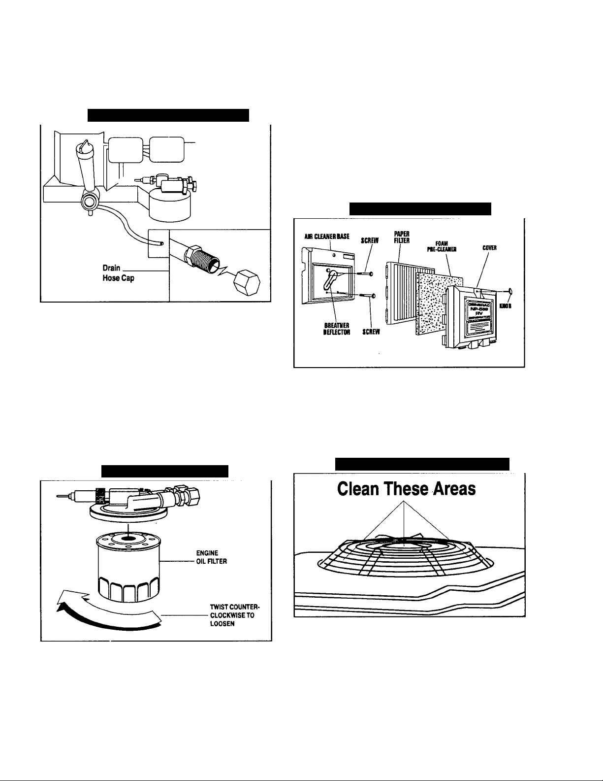
When oil has drained, install and tighten drain hose cap.
Remove oil dipstick and fill crankcase with the recom
mended oil (See Page 9). The engine crankcase can hold
about 1.7 liters (1.5 quarts). DO NOT FILL ABOVE “FULL”
MARK.
Install and tighten dipstick cap before operating engine.
Figure 10 — Oil Drain Hose and Cap
• Turn KNOB counterclockwise to loosen.
• Remove COVER, FOAM PRE-CLEANER and PAPER FIL
TER.
• Remove foam pre-cleaner from cover
• Wash foam pre-cleaner in liquid detergent and water.
• Wrap foam pre-cleaner in a cloth and squeeze dry.
• Saturate foam pre-cleaner in engine oil. Squeeze to
remove excess oil and to distribute oil.
• Install foam pre-cleaner Into cover, followed by paper filter.
Tabs at edges of paper filter must lock into slots on cover.
Once each year or every 100 operating hours
(whichever comes first), replace the paper filter. The
new replacement filter must be a flame retardent type.
Figure 12 — Engine Air Cleaner
CHANGE OIL FILTER
Replace the engine oil filter after the first 25 hours of
operation, every 200 operating hours thereafter.
• Turn oil filter counterclockwise to remove (Figure 11).
• Coat gasket of new filter with engine oil.
• Turn new filter clockwise until its gasket contacts tightly
with the filter adapter. Then tighten with an additional 3/4
to one turn by hand.
• Run engine and check for leaks.
NOTE: Check oil level and fill to full mark after check
ing for leaks. Filter will retain some oil.
Figure 11 —Engine Oil Filter
CLEAN AIR INTAKE SCREEN
Clean all foreign material from the air intake screen
(Figure 13) at lease once every 100 hours of operation.
Clean more often if necessary.
Inspect the area around the generator exhaust muffler
periodically and remove all grass, leaves, dirt, etc. from
this area.
Figure 13 — Cleaning Air Intake Screen
ENGINE AIR CLEANER
Clean and re-oil the foam pre-cleaner every three
months or ever 25 hours of operation, whichever
occurs first. Service the foam pre-cleaner more fre
quently if you operate the generator in extremely dusty
or dirty conditions (Figure 12):
— 12 —
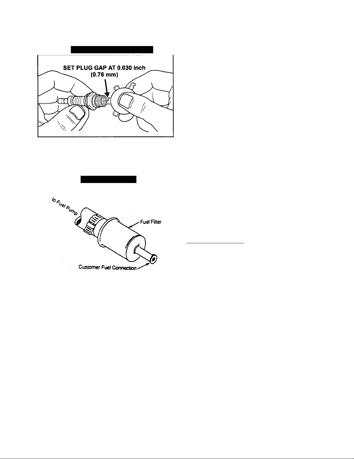
ENGINE SPARK PLUGS
Clean engine spark plugs and set gap to 0.030 inch
(0.76mm) every 100 hours of operation (Figure 14).
Clean by scraping or wire brushing and washing with,
commercial solvent. DO NOT BLAST CLEAN SPARK
PLUGS.
Page 13
CAUTION: Sparking can occur if wire terminai does
not fit firmly over spark plug terminal end. If neces
sary, reform wire terminal to obtain a tight fit.
Figure 14 — Engine Spark Plug
FUEL FILTER
Remove and replace fuel filter (Figure 15) every 100
hours of operation or once each year, whichever
occurs first.
Figuréis —Fuel Filter
WARNING: Be sure to re-install the plug from the
muffler tightly. Engine vibration couid cause a ioose
piug to fail out. Without the piug in place, hot engine
exhaust is directed out the opening. This hot
exhaust, depending on the installation, could be
directed to areas not able to withstand the extreme
heat such as wooden floor boards or other flammable
material. This could result in a fire.
CLEANING THE GENERATOR
Keep your generator set as clean and dry as possible.
Dirt and moisture that are permitted to accumulate on
electrical windings have an adverse affect on the insu
lation resistance of those windings.
Moisture that is allowed to remain in contact with wind
ings will be retained in voids and cracks of the wind
ings. Dirt makes the problem worse, since it tends to
hold the moisture into contact with the windings. Salt,
as from sea air, worsens the problem since it tends to
absorb moisture from the air. The combination of salt
and moisture makes a good electrical conductor.
CAUTION! Do NOT use a forceful spray of water to
clean the generator. Water will enter the generator
interior and cause problems, and may also contami
nate the generator fuel system.
SPARK ARRESTOR MUFFLER
If the generator is not equipped with a spark arrestor
exhaust muffler and is to be used on any forest cov
ered, brush covered or grass covered unimproved
land, you may have to install a spark arrestor. The
spark arrestor must be maintained in effective working
order by the vehicle owner/operator.
For assistance in ordering, installing and maintaining
spark arrestor exhaust mufflers, contact your nearest
authorized service facility.
Fxhaust mufflers supplied by Generac are spark
a.restor types. Generac exhaust mufflers for IM gener
ators do not have a spark arrestor screen, but are of
the more efficient “toriod” or “swirl” type. To remove
carbon and combustion deposits from such mufflers,
remove the PLUG from muffler and run engine for
about 15 minutes. Shut engine down, let the muffler
cool and Install the plug.
BAHERY
All lead-acid storage batteries will discharge when not
in use. Inspect the generator battery as follows:
■ ONCE WEEKLY
Inspect battery posts and cables for tightness, corro
sion. Clean and/or tighten as necessary.
Also check battery fluid level, and, if necessary, fill with
DISTILLED WATER ONLY. DO NOT USE TAP
WATER IN BATTERY.
■ EVERY SIX MONTHS
Flave the battery state of charge and condition
checked by an automotive service '
be done with an automotive type battery hydrometer.
DANGER: Storage batteries give off explosive
hydrogen gas. This gas can form an explosive mix
ture around the battery for several hours after
charging. The slightest spark can ignite the gas and
cause an explosion. Such an explosion can shatter
the battery and cause blindness or other injury.
Any area that houses a storage battery must be
properly ventilated. Do not allow smoking, open
flame, sparks or any spark producing tools or
equipment near the battery.
_______________________
rg<
facility. This should
— 13 —
Page 14

DANGER: Battery electrolyte fluid is an extremely
caustic sulfuric acid solution that can cause severe
burns. Do not permit fluid to contact eyes, skin,
ciothing, painted surfaces, etc. Wear protective
goggies, protective clothing and gioves when handiing a battery. If you spill the fluid, flush the affect
ed area immediately with clear water.
DANGER: Do not use any jumper cables or booster
battery to crank and start the generator engine. If
any battery has discharged, remove it from the vehicie for recharging.
• Attach a tag to the engine indicating the viscosity and clas
sification of the oil in the crankcase.
• Remove spark plugs and add about 1/2 ounce (15ml) of
clean, fresh engine oil into spark plug threaded openings.
Crank engine several times to distribute oil, then install
and tighten spark plugs.
• Remove the battery and store in a cool, dry room on a
wooden board. Never store the battery on any concrete or
earthen floor.
• Clean and wipe the entire generator.
RETURN UNIT TO SERVICE
MAJOR SERVICE MANUAL
To obtain a service manual for your generator, order it
from your dealer/distributor or contact the factory. Be
sure to identify your unit’s MODEL NUMBER and
SERIES.
DRIVE BELT
The engine drives the generator rotor by means of a
pulley and drive belt arrangement. The drive belt and
pulleys are warranted for the life of the generator.
Drive belt tension was properly adjusted before the unit
was shipped form the factory. If you suspect that drive
belt tension is incorrect, contact an autorized service
facility.
EXERCISING THE GENERATOR
Generac recommends that you start and operate the
generator at least once every seven days. Let the unit
run for at least 30 minutes to “exercise” the engine.
OUT OF SERVICE PROTECTION
If you cannot exercise the generator every seven days
and it is to be out of service longer than 30 days, pre
pare the generator for storage as follows:
• Start the engine and let it warm up.
• While the engine is still warm from running, drain the oil
completely. Refill crankcase with recommended oil. See
“Specifications.”
AFTER STORAGE
To return the unit to service after storage, proceed as
follows:
• Check tag on engine for oil viscosity and classification.
Verify that the correct recommended oil is used in engine.
If necessary, drain and refill with proper oil.
• Check battery. Fill all cells to the proper level with distilled
water. DO NOT USE TAP WATER IN THE BATTERY.
Recharge battery to 100% state of charge, or, if defective,
replace the battery.
• Press the Fuel Pump Primer switch and hold it for about
30 seconds.
• Turn OFF all electrical loads, then start the engine.
• Let engine warm up.
• Apply electrical loads to at least 50% of the unit’s rated
wattage capacity.
• When engine is thoroughly warmed up, shut it down.
THE GENERATOR IS NOW READY FOR SERVICE.
14
Page 15

TROUBLESHOOTING
PROBLEM POSSIBLE CAUSES REMEDY
Engine won’t crank. 1.
Engine cranks but won’t start. 1. Out of fuel. 1.
Engine starts hard, runs rough. 1.
Engine starts, shuts down
when Start/Stop switch is 2. Engine is overheated.
released.
15 amp fuse is blown
2. Loose corroded or defective
battery cables.
Defective engine Start/Stop switch. 3.
3.
4. Defective starter contactor.
Defective starter motor. 5.
5.
6. Low Battery Voltage. 6. Charge or replace battery.
2. Fuel pump is defective. 2.
Open Wire #14 from Eng. Control Bd. 3.
3.
4. Engine is flooded. 4. Wait 5-10 min. before trying.
Spark plugs defective. 5. Clean, regap or replace plugs.
5.
Air cleaner plugged or damaged 1. Clean or replace as needed.
2. Defective spark plugs.
1. Engine oil is low.
Defective Low Oil Pressure System 3. Have serviced/replaced.
3.
4.
Defective Engine Control Board
1. Replace 15 amp fuse
Tighten, clean or replace
2.
as necessary.
Replace Start/Stop switch.
4. Replace contactor.
Replace starter motor.
Replenish fuel.
Replace fuel pump.
Reconnect wire.
2. Clean, regap or replace plugs.
1.
Check oil; add as needed.
2. Check adequate ventilation.
4.
Have board serviced/replaced.
Start/Stop switch at Stop, 1. Defective Start/Stop switch
engine continues to run. 2. Open/disconnected wire #18 between
Start/Stop switch and Engine Control
3. Open/disconnected wire #0 between
Start/Stop switch & Engine Control Bd.
4.
Defective Engine Control Board
No AC output from generator.
Check circuit breaker. 1. Reset to ON or CLOSED.
1.
Check vehicle circuit breaker & fuses.
2.
Generator internal failure
3.
15
1. Replace switch.
2. Reconnect or close wire.
Reconnect or close wire.
3.
4. Replace board.
Reset and replace if necessary.
2.
Take generator to an
3.
Authorized Generac facility.
Page 16

ELECTRICAL DATA
Drawing No. A2693
16
Page 17

Drawing No. 92935
EXPLODED VIEW — SHEET METAL
ITEM
1 1 SEE ENG. EXP. VIEW OF 23
2 99258
3
4
5
6 A4456
7 86313
8 ■ 56893 23 SCREW (CRIMPTITE)- 33
10 87750
11 74916 1 COVER-BASE #2 35
12
13
14 78858 1 COVER, VALLEY 37 38153 2
15 78859
16 74902 2 WRAPPER-BARREL 39 33469 2
17 66476 4 HHCS/LWM6-1.0X12MM 40
19 73191 1
20 48571 2 CAPSCREW, HEX HEAD-
21
22 75246
PART NO. QTY. DESCRIPTION
ENGINE
1 KEY, WOODRUFF- 25 73186
6 X 22 MM 26 81108 1 BUSHING, SNAP
67198N 1 BEVELLED WASHER
67890
87865
74908
73190 1 WRAPPER-NO. 2 CYLINDER 36
22129 2 LOCKWASHER-M8
1 HEX NUT 28
1 PLUG. FLYWHEEL ACCESS 29 67866
1 3/8“ SPECIAL LOCK WASHER 30 77001
1
HOUSING, ENGINE TOP 31
NO. 10-24 X 1/2" CYL. #2
1 SCROLL, FLYWHEEL 34 29289
9 SCREW (TAPTITE)-M5 x 10MM
1
WRAPPER-NO. 1 CYLINDER
COVER, BASE-NO. 1 CYL.
M8-1.25X 15MM
4
SCREW (TAPTITE)-
3/8"-16x 1-1/4“
ITEM PART NO.
10-74260
24
27 22717-B
38 22152 2
41 92934
42 22158 2
17
88290
22717-A 2
73132 2
87858A 1 GROUND WIRE ASSEMBLY.-
87858B 1 GROUND WIRE ASSEMBLY50277
23897
QTY. DESCRIPTION
2 FT. FOAM TAPE
1 WIRE ASSEMBLY-NO. 16
1 COVER, STARTER
1 WRAPPER, CRANKCASE
1 GROMMET-RUBBER
GROMMET-RUBBER
1
0-RING
1 PLUG, OIL FILL
BOOT, SPARK PLUG
CYL. #1
DECAL. OIL DRAIN
1
NO. 10-32 x 1-1/2“ SCREW
NO. 10 LOCK WASHER
0.22 INCH 1.0. SPACL.H
NO. 10 FLAT WAS !' 1
S.
1
REGULATOR-ЮЛ
NO. 10-32 HEX NUT
Page 18

EXPLODED VIEW — BASE & PULLEYS
Drawing No. 91356
O' >0 CO xo
CM o n
— 18 —
Page 19

Drawing No. 91356
REPAIR PARTS — BASE & PULLEYS
ITEM PART NO. QTY.
1 86318 1
90141 1 GROUND CABLE
2
3 46911
4 MOUNT, (RUBBER)
4 25017 8
DESCRIPTION ITEM PART NO.
BASE, MOUNTING 45
CAPSCREW, HEX HD.-
3/8"-16x 1/2“ 50
5 46526 10
6 22129 2
7 72391 2
77603 2
8
9 22259
10
11
52858 6
51730
2 NUT, HEX-5/16-18
2 CAPSCR. HEX HD.
LOCKWASHER, M10 56
LOCKWASHER-M8
SKID, RUBBER MOUNT
HHCS-5/16-18X3.5 SPC
NUT, FLANGED LOCK-M8-125
M8-1.25X60MM
12 29459
13 75215
14 73146
15 75209
16
73174 1
17 79678
2
2 WASHER, SPRING CNTR
4
2
2
SPRING, BELT TENSION
SLIDE (NYLON)
SUPPORT, NYLON SLIDE
MANIFOLD, EXHAUST
GASKET, EXHAUST
MANIFOLD
18
55173
4 CAPSCR., HEX HD.-M8-1.25
X20MM (GRADE 10.9)
19
72383 2
20 90859
21 75224F 1
22
23
73106F 1
75216 1
1 COVER PLATE - EXT.
GASKET, COLLECTOR PAN
PULLEY, ENGINE
PULLEY, ALT.
BELT (POLY V 4L)-40"
24 49451 1 WASHER, PULLEY
25 42633
1 CAPSCR., SOCKET HD.
3/8"-24 X 1 (GRADE 5)
26
77017 1 GUIDE, BLOWER HOUSING
27 73118 1 CAPSCR., HEX HD.
3/8"-24 X 2-1/4”
28
74906
4 SCREW (TAPTITE)
M6-1.00X20
29 91123
1 SCREW (TAPTITE)
M5-0.80X 10
30 72375
31 73185
1
HOUSING, BLOWER
1 SPACER, BLOW. HOUSING
32. 22097 7 LOCKWASHER, M6
33
77682 1 CAPSCR. HEX HD.
M5-0.80 X 80MM
34
75242
35 ■ 49813 2
36 45757 2
4 SPRING, GENERATOR SET MT
NLTT,HEXM6X1.0
CAPSCREW, HEX HD.,
M6-1.0X25LONG
37 90475
1
COVER PLATE
38 87769 1 CLAMP, HOSE-SB"
39 87768 1 FFTTING-I/BPIPT01/4 TUBE
40 87770
42 26925
43
75710-A 1
44 74958
1 FUELUNE
1 3BNPT OIL DRAIN
TUBE, OIL RLL AND DRAIN
1
CAP & DIPSTICK ASSEM.
QTY. DESCRIPTION
67871 1
47 75711
48 A5802
49 4S508
1 PIPE, OIL DRAIN ADAPTOR
1 TINNERM/VvICUP
1 OIL FILL TUBE GASKET
0-RING, CAP
22413 1 ELBOW-3B’NPTX3B”
73179
57 70185
58 bd108
59 74948 3
60
74950
61 74951
62
73134 1
63 38750 3
1
OIL FILTER SUPPORT
1 FILTER, OIL
1 10 PSI OIL PRES. SWITCH
FITTING-5/16"
1
1
TUBE, OUTER OIL
TUBE, INNER OIL
ADAPTOR, OIL PAD
CAPSCREW, HEX HEAD-
M6-1.00 X 30MM
64 74949
65
66
68548 1
62684 1 LUG, GROUNDING
1 FITTING, 90-DEGREE-5/16"
GASKET, OIL PAD
67 29289 - TAPE, FOAM-1/16" THICK x 8'
69 75281
70
71
73
74027 2 SCREW, PAN HEAD-M3-0.50
43182 2 LOCKWASHER-M3
75237 4 WASHER, SPRING RETAINER
74 77681
75
75474
76 90800
1 SWITCH, HIGH TEMP.
1 CAP, VINYL-LOS-2 WIRE
1
1
CAP, VINYL-17Dx42Lx2H
ELBOW, EXHAUST
- UNIVERSAL
77
78
74907 1
75226 1 COVER, AIR
79 56893
14 SCREW (CRIMPTITE)
CLAMP, EXHAUST-1-1/8"
NO. 10-24 X 1/2" LONG
80 75229
81
75227
82 79246
1
1 SLIDE PAN
4
GASKET, SLIDE PAN
CAPSCREW, HEX HEAD
M6-1.00X 16MM WITH
LOCK WASHER
83
85
22473 5
72384C 1
87 77643 2
90
22447 1
FLATWASHER, M6
COVER, EXHAUST OUTLET
GASKET, EXHAUST OUTLET
LOCK WASHER-M6,
TOOTHED
91
90088 1
92 74908 10
FUEL PUMP BRACKET
M6X 10MM TAPTITE
SCREW
93
a4-roS
94 23897 6
95
67210 1 FUEL LINE
96 90088 9
97 22131
98
68527
2
/■
't Capscrew, hex md, -
FUEL FILTER
1/3” PIPE TO 1/4” TUBE
ri i ' ii'JG
vinyl (JOATEO Ci..,\[v.: ‘
M1D FLAT WA-S'r L .
M6-1.00X20MM WITH
LOCK WASHER
— 19 —
Page 20

EXPLODED VIEW — CONTROL PANEL
Drawing No. A2687
— 20 —
Page 21

REPAIR PARTS — ALTERNATOR & CONTROL PANEL
Drawing No. A2687
#
ITEM
PART NO.
1 75995 1 LOWER BEARING CARRIER
2 80095H 1
A2592H 1 STATOR ASSEMBLY 36 82737
3
4
73159 1 BALL BEARING
5 31971 1 BALL BEARING 38 49815
6 72379B 1 UPPER BEARING CARRIER 39
7
77006
52858 8 M8-1.25 FLANGE LOCK NUT 42
8
9
66386
10 66849 2 M5-0.8X16LG.TAPT1TE
11 27756 4 NYLON WASHER 45 51716
12 86341
13 A8475
14 22473 2
22097 4
15
17 90141 2
18 22447 1
19 74906
92234 1
20
21 010-74260 1 STARTER CABLE 54 87798 1 SWITCH S.P.D.T. 6A
22 22129 2
23 22259 2 5/16”-18HEXNUT
24
86316
25 53650
26 20575
27 75244 1
66886 2 M6-1.0 X 12MM CAPSCREW
28
29 56739 1
30 75476 4 M4-0.7 X 16 LG. CAPSCREW 63 23897 1
31 22264 5 M4-.LOCK WASHER 64
32 38077 1 CIRCUIT BREAKER 15A.
90987 2
33
QTY. DESCRIPTION ITEM
ROTOR ASSEMBLY 35 75235
4
STUD-STATOR
1 BRUSH HOLDER 43 83049 1
1
GEN. TOP HOUSING 47 A2598
1
M5-SPEC1AL LOCK WASHER 48
M6-FLAT WASHER
M6-LOCK WASHER 50
GROUND CABLE W/LOCK WASHER & FLAT
SHAKEPROOF LOCK
WASHER
4 M6-1.0X20LG.TAPTITE 52 32300 1
CONTROLLER P.C.B. 53
5/16” LOCK WASHER (START-STOP)
1 PANEL SHEET METAL PUMP)
1
4-PIN CONNECTOR 56
1
CONNECTOR
REMOTE HARNESS 58 51715
STARTER CONTACTOR
M3-0.5 X 12 LG. CAPSCREW
PART NO.
34 86317A 1
37
49813
43182 2
41
5'^ j02
22264 1
44
22152 6 M5-LOCK WASHER
25105 4
49 86315
90734 4
51 22985 3 M4-FLAT WASHER
22676 1
55 92113
75210A
57
23365
90157A 1
59
62
31791
74908
65 23484-S
QTY. DESCRIPTION
PANEL SUPPORT BRACKET
4
M5-0.8 X 30 LG. CAPSCREW
4
VIBRATION MOUNT
4
M6-1.0 HEX NUT
1
M5-0.8X 16LG. HHCS
M3-LOCK WASHER
1
C/BREAKER 3.0A
M5 SHAKEPROOF WASHER
REGULATOR VOLTAGE
4
M5-0.8 HEX NUT
1
C/BREAKER 25A. 3 POLE
PRHMS #6-32 X 1/4” SEMS
1
PANEL COVER
M4-0.7 X 16 LG. CAPSCREW
WASHER
FUSE HOLDER
FUSE AGC-15A.
1
SWITCH S.P.S.T. (FUEL
1 TERMINAL BLOCK
1
M4-SHAKEPROOF WASHER
1
M4-0.7 HEX NUT
DECAL, CB RATING 25A.
1 CLAMP, CABLE
M5-FLAT WASHER
1
M5X 10LONG TAPTITE
1
BUSHING
21
Page 22

REPAIR PARTS — CARBURETOR
Drawing No. 98692
ITEM PART NO. QTY.
1 73112B 1
2
74962E
74962B 1
74962G 1 SPRING, GOVERNOR-(IM7.2) 21
3
70155
4
70108 1 ROD, GOVERNOR TO GARB.
5 56893 5 SCREW (CRIMPTITE)
6
74961
7
47227 1
3 37398
9 73131 1 BRCKT., AIR CLNR. SUPPORT
10 66476 2
11
72310 2
12
70125
13 73374 1 BRACKET, CHOKE SUPPORT
14 74947 1 ROD, CHOKE CONTROL
15 89473 1 BI-METAL ASSEMBLY, CHOKE
• 16 91306
17
77091
DESCRIPTION ITEM PART NO. QTY.
CARBURETOR ASSEMBLY 18 31879 4
1
SPRING, GOVERNOR-(IM5.2) 19 22159 4
SPRING, GOVERNOR-(IM6.6) 20 89870 1
1
LEVER, GOVERNOR
NO. 10-24x1/2" 25 47662T 1
1
BRACKET, GOV. ADJUSTER
SCREW, GOV. ADJUSTER 81378A 1 DECAL, AIR CLEANER-(IM6.6)
1
NUT, HEX LOCK (NYLON) 81378B 1 DECAL, AIR CLEANER-(IM7.2)
SCREW, HEX-M6-1.00X 12MM 27 75252 1 KIT, CARBURETORSCREW, HEX-M6-1.00 x 25MM
1
SPRING, ANTI-LASH
1
SOLENOID, CHOKE
1
HAIRPIN, COTTER-.0901
— 22 —
DESCRIPTION
FLATWASHER-NO.'4 .
LOCKWASHER-NO. 4 •
SOLENOID FUEL SHUT-OFF
72536
22 87770 1 LINE, FUEL-5/16" ID.
23 74946 1 LINK, CHOKE
26 81378
A2603 1
28
73130
29 40173 2 CLAMP, HOSE (SCREW TYPE)
30 66829 2 ALUMINUM RIVET-3MM
75944 1
31
32 70594
33 77075 1 COVER, CHOKE COIL
4 SCREW, PAN HD. MACH.
NO. 4-46 X 1/4"
HOSE-FUEL, 4.5" LG
1
DECAL, AIR CLEANER-(IM5.2)
DECAL, AIR CLEANER-(IM7.2 3PH)
OVERHAUL-NOT SHOWN
1 FLYWHEEL ASSEMBLY
BRACKET, GOVERNOR SPRING
2 CAPSCREW, HEX HD.
M6-1.0 X 93 LG, W/WASHER
Page 23

Drawing No. 79216
EXPLODED VIEW — V-TWIN ENGINE PARTS
5I
~CX
440
43«
6<S>
1 vun ovHHUi in 1
33—'
S-33
3S-| ^^41
— 23 —
MEOUMB WECUL TQQU TO INSTUL
sa REPAR «Simiaiott lUNUAL
fC=Dc-2’
21
63-
60-t-38
---
-
Page 24

EXPLODED VIEW — V-TWIN ENGINE PARTS
Drawing No. 79216
94-
-28 .
-29
— 95
97-
96
— 24 —
Page 25

EXPLODED VIEW — V-TWIN ENGINE PARTS
Drawing No. 79216
ITEM PART NO. QTY. DESCRIPTION ITEM PART NO. QTY. DESCRIPTION
1
69331
2
69333
3 67805
4 79234 1 CYLINDER HEAD 38
5 79235
6 70169
7 69332 2 GASKET-CYLINDER HD. 43 75253
8 72301
9 72315
10 70190
11
70596
12
69336
13
69325
14
67888
72334 1 CRANK SHAFT ASSM.
15
75247
16
67924 1 OIL SEAL-35 DIAMETER 76 67910
17
18 67878 9
19 75248
20 75249
21 69327 4 LOCKING RING, PISTON 81
22
75250
23 75251
24
72346
25 69316
69317 2 INTAKE VALVE
26
27
67816
28 69320
29 70513
70584 4 TAPPET, VALVE 87 80011
30
31 70530
32 72358
33 69379
34
67895
70594 2 BOLT, CARB. MNTG.
35
1 CVLII^DEft aSSemblV
1
SLEEVE BEARING-30 DIA.
1 OIL SEAL-30 DIAMETER 37
ASSEM.-NO. 1 39
1 CYLINDER HEAD 40
ASSEM.-NO. 2
4
SEALING WASHER
1 BREATHER ASSEMBLY
1 GASKET, BREATHER 44
1 SCREW, BREATHER
1 TUBE, BREATHER
1 GASKET, OIL SUMP
BOLT, CYLINDER HEAD
8
2
PLUG, OIL DRAIN-3/8" NPT 73
1 OIL SUMP ASSEMBLY
BOLT, OIL SUMP 77 67911 2 SEAT, EXHAUST VALVE
PISTON ASSM.-STANDARD
2
2 RING SET- PISTON 79 75268
-STANDARD
2 PISTON PIN-STANDARD 82 73123
2
CONNECTING ROD ASSM.
4 BOLT, CONNECTING ROD 83 70593
2 EXHAUST VALVE
4
VALVE SPRING 85
4 RETAINER, VALVE SPRING
4
KEEPER,VALVE 86
1 CAMSHAFT ASSEMBLY 88 70597 1 TUBE, AIR INLET
1 INTAKE MANIFOLD
2 GASKET, CARB. MNTG.
2 GASKET, INTAKE 91 69328 1 ROCKER ARM COVER
MANIFOLD 92
36 67158
68574 1
68554 1 SEAL, GOV. SHAFT
68573
70506
41 70554 1
42 7 568
67885
75254 4 SCREW, VALVE ADJUST
45
46 70535
47
75255
48 75256
68572
74 75272 2 TERMINAL, SPARK PLUG
70122 2 SEAL, VALVE STEM
75
78 67813
75270
80
70592 1 AIR CLEANER BASE
84
72300
67156 2
69341 1 PRE-FILTER
89 69358
90 67920
70547 1
4
MANIFOLD MNT.
PIPE-PLUG, 1/8" NPT
1
0-RING, OIL PUMP
1 0-RING, OIL GALLEY
SPACER, CARBURETOR
4 STUD, ROCKER ARM
4 SEAL, WASHER
-VALVE COVER
4
NUT, NYLOK-M6
1
SCREEN, OIL
1 STARTER MOTOR
2 BOLT, STARTER MOTOR
2 SCREW, OIL PUMP
2 SEAT, INTAKE VALVE
4 VALVE, GUIDE
1 RETAINER AND PIN
1 ROLL PIN
1
AIR FILTER
(FLAME RETARDENT)
1 COVER, AIR CLEANER
1 SCREW, AIR CLEANER
COVER
SCREW, AIR CLEANER
BASE
1 SPRING, BRUSH SET
1 DEFLECTOR-BREATHER
2 GASKET, VALVE COVER
OIL PUMP ASSEMBLY
— 25 —
Page 26

CALIFORNIA EMISSION CONTROL WARRANTY STATEMENT
YOUR WARRANTY RIGHTS AND OBUGATIONS
The California Air Resources Board (“CARB“) and Generac Corporation are pleased to explain the Emission Control System
Warranty on your new industrial mobile (IM) generator. In California, new utility and lawn and garden equipment engines
must be designed, built and equipped to meet the State's stringent anti-smog standards. Generac Corporation will warrant
the emission control system on your industrial mobile (IM) generator for the periods of time listed below provided there has
been no abuse, neglect, unapproved modification, or improper maintenance of your industrial mobile (IM) generator.
Your emission control system may include parts such as the carburetor, ignition system and exhaust system. Also included
may be the compression release system and other emission-related assemblies.
Where a warrantable condition exists, Generac Corporation will repair your industrial mobile (IM) generator at no cost to
you for diagnosis, parts and labor.
MANUFACTURER’S EMISSION CONTROL SYSTEM WARRANTY COVERAGE:
Emissions control systems on 1995 and later model year utility and lawn and garden equipment engines are warranted for
two years as hereinafter noted. If, during such warranty period, any emission-related part on your engine is defective in
materials or workmanship, the part will be repaired or replaced by Generac Corporation.
OWNER’S WARRANTY RESPONSIBILITIES:
As the industrial mobile (IM) generator owner, you are responsible for the performance of the required maintenance listed
in your owners manual. Generac Corporation recommends that you retain all receipts covering maintenance on your indus
trial mobile (IM) generator, but Generac Corporation will not deny warranty solely due to the lack of receipts or for your
failure to provide written evidence of the performance of all scheduled maintenance.
As the industrial mobile (IM) generator owner, you should, however, be aware that Generac Corporation may deny you war
ranty coverage if your industrial mobile (IM) generator or a part thereof has failed due to abuse, neglect, improper mainte
nance or unapproved modifications.
You are responsible for presenting your industrial mobile (IM) generator to a Generac Corporation Authorized Service
Outlet as soon as a problem exists. The warranty repairs should be completed in a reasonable amount of time, not to exceed
30 days.
Warranty service can be arranged by contacting either a Generac Corporation Authorized Service Outlet or by contacting
Generac Corporation at;
GENERAC CORPORATION PH: (414) 544-4811
P.O.BOX8 FX:(414)544-0179
WAUKESHA, Wl 53187
IMPORTANT NOTE: This warranty statement explains your rights and obligations under the Emission Control System
Warranty ("ECS Warranty") which is provided to you by Generac Corporation pursuant to California law. See also the
Generac Corporation Limited Warranties for Generac Corporation which is enclosed herewith on a separate sheet and also is
provided to you by Generac Corporation. The ECS Warranty applies only to the emission control system of your new engine.
To the extent that there is any conflict in terms between the ECS Warranty and the Generac Corporation Warranty, the ECS
Warranty shall apply except in any circumstances in which the Generac Corporation Warranty may provide a longer warran
ty period. Both the ECS Warranty and the Generac Corporation Warranty describe important rights and obligations with
respect to your new engine.
Warranty service can only be performed by a Generac Corporation Authorized Service Outlet. At the time of requesting
warranty service, evidence must be presented of the date of the sale to the original purchaser. The purchaser shall pay any
charges for making service calls and/or for transporting the products to and from the place where the inspection and/or war
ranty work is performed. The purchaser shall be responsible for any damage or loss incurred in connection with the trans
portation of any engine or any part(s) thereof submitted for inspection and/or warranty work.
Page 27

GENERAL SAFETY RULES
THE MANUFACTURER SUGGESTS THAT THESE “RULES" FOR SAFE OPERATION BE
COPIED AND POSTED IN POTENTIAL HAZARD AREAS OF THE GENERATOR. SAFETY
SHOULD BE STRESSED TO ALL OPERATORS AND POTENTIAL OPERATORS OF THIS
EQUIPMENT.
tudy these SAFETY RULES carefully before operat
ing or servicing applicable equipment. Become familiar
with this Owner's Manual and with your generator.
Safe, efficient and reliable operation can only be
achieved if generator is properly installed, operated
and maintained. Many accidents are caused by failing
to follow simple and fundamental rules or precautions.
The manufacturer suggests that these GENERAL
SAFETY RULES be copied and posted in potential
hazard areas of the generator. Safety should be
stressed to all operators and potential operators of
equipment.
The manufacturer cannot possibly anticipate every cir
cumstance that might involve a hazard. The warnings
in this Manual and on tags and decals affixed to the
unit are, therefore, not all-inclusive. If you use a proce
dure, work method or operating technique Generac
does not specifically recommend, you must satisfy
yourself that it is safe for you and others. You must
also make sure the procedure, work method or operat
ing technique that you chose does not render the gen
erator to be unsafe.
For fire safety, the industrial mobile generator must be
properly installed and maintained. Installation must
always remain in compliance with applicable codes and
standards. In addition, the generator must be installed
in conformance to the manufacturer's detailed installa
tion instructions. Following installation, nothing must be
done that might render the generator in noncompliance
with such codes, standards and instmctions.
A The INDUSTRIAL MOBILE generator produces
^ extremely high and dangerous electrical voltages and
can cause dangerous, and possibly fatal, electrical
shock. Avoid contact with bare wires, terminals, etc.
while the unit is running. If you must work around an
operating generator, stand on an insulated, dry surface
to reduce shock hazard.
• Never work on this equipment or handle any electrical
device while standing in water, while barefoot, or while
hands or feet are wet. Dangerous electrical shock will result.
• Have the generator properly grounded (bonded) during
installation onto the vehicle, either by solid mounting to
the vehicle frame or chassis or by means of an
approved bonding conductor. DO NOT disconnect the
bonding conductor, if so equipped. DO NOT reconnect
the bonding conductor to any generator part that might
be removed or disassembled during routine mainte
nance. If the grounding conductor must be replaced,
use only a flexible conductor that is of No. 8 AWG cop
per wire minimum.
• In case of accident caused by electric shock, shut
down the source of electrical power down at once. If
this cannot be done, free victim from live conductor.
AVOID DIRECT CONTACT WITH THE VICTIM. Use a
dry board, dry rope, or other non-conducting imple
ment to free the victim. If the victim is unconsious
apply first aid and get medical help.
Inspect fuel system frequently for leaks or damage.
Repair or replace any damaged or leaking component
immediately. Never attempt to change, alter or modify
the generator fuel system in any way that might affect
safety or compliance, with applicable codes and stan
dards.
The gener^.tor engine gives off DEADLY carbon
monoxide gas through its exhaust system. This dan
gerous gas, if breathed in sufficient concentrations,
can cause unconsciousness or even death. This
exhaust system must have been properly installed, in
strict compliance with applicable codes and standards.
Following installation, you must do nothing that might
render the system unsafe or in non-compliance with
such codes and standards. The generator compart
ment must be completely vapor sealed from vehicle
interior. There must be no possibility of exhaust fumes
entering the vehicle interior. Never operate this equip
ment with a leaking or defective exhaust system.
Never use the generator or any of its parts as a step.
Stepping on the unit can stress and break parts and
may result in dangerous, fuel leakage, oil leakage, etc.
Do not smoke around the generator. Wipe up all fuel,
and oil spills immediately. Never leave oily or fuel
soaked rags in the generator compartment or on the
generator itself. Keep the area around the generator
clean and free of debris.
Adequate ventilation is required to expel toxic fumes
and fuel vapors from the generator compartment. Do
not alter the installation of this equipment in any man
ner that might obstruct air and ventilation openings.
Such openings must be kept clear and unobstructed.
Keep hands, feet, clothing, etc., away from drive belt,
fans and other moving parts of this equipment. Never
remove any drive belt or fan guards while the unit is
operating.
Inspect the generator periodically. Repair or replace all
damaged or defective parts immediately.
These generators can be converted to use LP gas
(propane) as a fuel. Liquid Propane gas is highly
EXPLOSIVE. The gas is heavier than air and tends to
settle in low areas where even the slightest spark can
ignite the gas and cause an explosion.
Before performing any maintenance on the generator
set, disconnect its battery cables to prevent accidrnial
start up. Disconnect the cable from the battery post
indicated by a NEGATIVE, NEG or (-) first. Reconnect
that cable last.
Page 28

GENERAC S 1-YEAR LIMITED WARRANTY
FOR
IM SERIES INDUSTRIAL MOBILE GENERATORS
Generac warrants to the original purchaser that its generators will be free from defects in materials or workman
ship for the period set forth below from date of original purchase. During said warranty period, Generac will, at its
option, repair or replace any part which, upon examination by Generac or Generac Authorized Distributors and/or
Dealers, is found to be defective under normal use and service.
1-YEAR WARRANTY SCHEDULE
1. All IM series generators used in an industrial vehicle shall be warranted from date of purchase for a period of
a 1 year or 2000 hours of operation, whichever occurs first. All parts, labor, removal and reinstallation shall be
covered during this period.
2. The drive train, belt and pulleys on IM series air-cooled generators shall be warranted against failure due to
defective materials or normal usage for the life of the generator. For the original owner, this drive train warranty
shall include parts and labor plus a $50.00 payment upon return of the failed belt or pulley parts only.
All warranty expense allowances are subject to the conditions defined in the PUBLISHED GENERAC POLICIES
AND PROCEDURES manual.
This warranty does NOT cover:
• Costs of maintenance, installation and startup.
• Failures due to normal wear, accident, misuse, abuse, negligence or improper installation.
• Products which are modified or altered in a manner not authorized by the manufacturer in writing.
• Incidental, consequential or indirect damages caused by defects in materials or workmanship, or any delay in repair or
replacement of defective parts.
• Failure due to misapplication.
• Telephone, telegraph, teletype or other communications expenses.
• Living or travel expenses of persons performing service.
• All transportation/travel expenses.
• Rental equipment used while warranty repairs are being performed.
• Overtime labor.
• Starting batteries, fuses, light bulbs and engine fluids.
This warranty is in place of all other warranties, express or implied. Specifically, Generac makes no other war
ranties as to merchantability or fitness for a particular purpose. Generac’s only liability shall be the repair or
replacement of parts as stated above. In no event shall Generac be liable for any incidental or consequential
damages, even if such damages are a result of Generac’s negligence. Buyer agrees to make no claims against
Generac based on negligence.
GENERAC POWER SYSTEMS INC.
P.O. BOX 8
WAUKESHA, Wl 53187
Telephone: (414) 544-4811
Fax: (414)544-4851
 Loading...