

Page 1

V
Part No. 98773
OWNER’S
Manual
Series Q-55G and Q-70G
AIR-COOLED
RECREATIONAL VEHICLE
GENERATORS
Model Nos. 9592-3 and 9593-3
Revision 1 (06/02/98)
C O R P ORATION
Printed in U.S.A.
Page 2

GENERAL SAFETY RULES
THE MANUFACTURER SUGGESTS THAT THESE "RULES" FOR SAFE OPERATION BE COPIED AND
POSTED IN POTENTIAL HAZARD AREAS OF THE INDUSTRIAL VEHICLE. SAFETY SHOULD BE STRESSED
TO ALL OPERATORS AND POTENTIAL OPERATORS OF THIS EQUIPMENT.
Study these SAFETY RULES carefully before operating
or servicing applicable equipment. Become familiar
with this Owner's Manual and with your generator. Safe,
efficient and reiiable operation can only be achieved if
generator is properly installed, operated and main
tained. Many accidents are caused by failing to follow
simple and fundamental rules or precautions. The man
ufacturer suggests that these GENERAL SAFETY
RULES be copied and posted in potential hazard areas
of the industrial vehicle. Safety should be stressed to
all operators and potential operators of equipment.
The manufacturer cannot possibly anticipate every pos
sible circumstance that might involve a hazard. The
warnings in this Manual and on tags and decals affixed
to the unit are, therefore, not all-inclusive. If you use a
procedure, work method or operating technique
Generac does not specifically recommend, you must
satisfy yourself that it is safe for you and others. You
must also make sure the procedure, work method or
operating technique that you chose does not render the
generator to be unsafe.
• For fire safety, the industrial mobile generator must
be properly installed and maintained. Installation
must always remain in compliance with applicable
codes and standards. In addition, the generator
must be installed in conformance to the
manufacturer’s detailed installation instructions.
Following installation, nothing must be done that
might render the generator in noncompliance with
such codes, standards and instructions.
• The RV generator produces extremely high and
dangerous electrical voltages and can cause dan
gerous, and possibly fatal, electrical shock. Avoid
contact with bare wires, terminals, etc. while the
unit is running. If you must work around an operat
ing generator, stand on an insulated, dry surface to
reduce shock hazard.
• Never work on this equipment or handle any elec
trical device while standing in water, while barefoot,
or while hands or feet are wet. Dangerous electri
cal shock will result.
• Have the generator properly grounded (bonded)
during installation onto the vehicle, either by solid
mounting to the vehicle frame or chassis or by
means of an approved bonding conductor. DO
NOT disconnect the bonding conductor, if so
equipped. DO NOT reconnect the bonding conduc
tor to any generator part that might be removed or
disassembled during routine maintenance. If the
grounding conductor must be replaced, use only a
flexible conductor that is of No. 8 AWG copper wire
minimum.
• Inspect the generator periodically. Repair or re
place all damaged or defective parts immediately.
• In case of accident caused by electric shock, shut
down the source of electrical power down at once.
If this cannot be done, free victim from live conduc
tor. AVOID DIRECT CONTACT WITH THE VICTIM. Use a dry board, dry rope, or other non-con
ducting implement to free the victim from live con
ductor. If victim is unconscious, apply CPR (cardio
pulmonary resuscitation) and get medical help.
Inspect fuel system frequently for leaks or damage.
Repair or replace any damaged or leaking compo
nent immediately. Never attempt to change, alter
or modify the generator fuel system in any way that
might affect safety or compliance with applicable
codes and standards’.
The generator engine gives off DEADLY carbon
monoxide gas through its exhaust system. This
dangerous gas, if breathed in sufficient concentra
tions, can cause unconsciousness or even death.
This exhaust system must have been properly in
stalled, in strict compliance with applicable codes
and standards. Following installation, you must do
nothing that might render the system unsafe or in
non-compliance with such codes and standards.
The generator compartment must be completely
vapor sealed from vehicle interior. There must be
no possibility of exhaust fumes entering the vehicle
interior. Never operate this equipment with a leak
ing or defective exhaust system.
Never use the generator or any of its parts as a step.
Stepping on the unit can stress and break parts and
may result in dangerous operating conditions from
leaking exhaust gases, fuel leakage, oil leakage,
coolant leakage, etc.
Do not smoke around the generator. Wipe up any
fuel, oil and coolant spills immediately. Never leave
oily or fuel soaked rags in the generator compart
ment or on the generator itself. Keep the area
around the generator clean and free of debris.
Adequate ventilation is required to expel toxic
fumes and gasoline vapors from the generator com
partment. Do not alter the installation of this equip
ment in any manner that might obstruct air and
ventilation openings. Such openings must be kept
clear and unobstructed.
Keep hands, feet, clothing, etc., away from drive
belts, fans and other moving parts of this equip
ment. Never remove any drive belt or fan guards
while the unit is operating.
Some generators may use LP gas (propane) as a
fuel. LP gas is highly EXPLOSIVE. The gas is
heavier than air and tends to settle in low areas
where even the slightest spark can ignite the gas
and cause an explosion.
Before performing any maintenance on the gener
ator set, disconnect its battery cables to prevent
accidental start up. Disconnect the cable from the
battery post indicated by a NEGATIVE, MEG or (-)
first. Reconnect that cable last.
Page 3
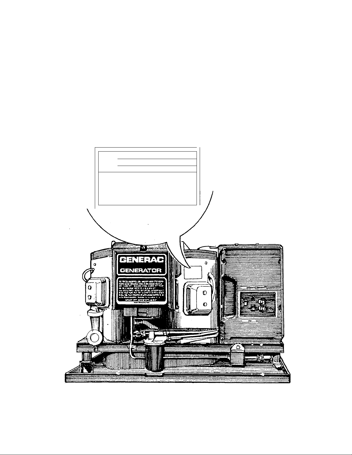
IDENTIFICATION RECORD
Please record the following information, from the generator DATA PLATE or information decai:
1. Modei Number
3. kW Rating,
5. Phase
______
r
NDIieL[
SERIES [
SERIALr
V
___________________
2. Serial Number____________________________
4. Rated Voltage,
6. Hertz
1 VO.TSI 1
1 *HPS| 1
1 WATTS 1 1
PHASE-1 HERT2-«0 RPM-VARIA8LE____________
CLASS r INSULATION AT 40*C CtXTINUOUS DUTY
FDR SERVICE CENTER LOCATIONS
CALL 800-333-1332 — 24 HOURS A DAY
GENERAC CORPORATION
VAUKESHA, WIS
U.S. AND FOREIGN PATENTS PENDING
MADE IN U.S.A.
__________
I -
Page 4

TABLE OF CONTENTS
GENERAL SAFETY RULES.
IDENTIFICATION RECORD
READ THIS MANUAL THOROUGHLY
Operation and Maintenance............................................ 3
How to Obtain Service
GENERATOR FEATURES................................................ 4
GENERATOR FAMILIARIZATION
Generator Applicability.................................................... 5
Installation....................................................................... 5
Safety.............................................................................. 5
Generator AC Connection System
OPERATING INSTRUCTIONS
Generator Panel
Automatic Choke
Before Starting the Engine
Starting
Stopping the Generator
Applying Loads to Generator
Wattage Reference Guide
ADDITIONAL INFORMATION
Automatic Low Oil Pressure Shutdown
High Temperature Shutdown
Muffler Kits...................................................................... 9
Field Boost
Over-Voltage Protection
25-Hour Break in Period................................................10
25-Hour Check Up.........................................................10
Operation in High Grass or Brush
...........................................................................
.............................................................
............................................................
.....................................................................
..........................
.............................................
....................................................
.................................
.............................................
..................................................
..........................................
..............................................
.........................................
.................................................
.................................
inside cover
.............................
..........................
10
SPECIFICATIONS
1
3
3
Generator Specifications..........................................11
Engine Specifications...............................................11
Fuel Requirements...................................................11
Engine Oil Requirements
.........................................
11
Optional LP Gas Fuel System..................................11
MAINTENANCE
Checking Engine Oil Level........................................12
Change Engine Oil....................................................12
Change Oil Filter.......................................................12
5
Engine Air Cleaner....................................................13
Clean Air Intake Screen............................................13
Engine Spark Plugs
6
6
7
7
7
7
8
Fuel Filter..................................................................13
MISCELLANEOUS MAINTENANCE
Spark Arrestor Mufflers.............................................14
Cleaning the Generator
Battery.......................................................................14
Major Service Manual
Drive Belts
................................................................14
Exercising the Generator
9
9
9
9
Out of Service Protection...........................................15
Return the Unit to Service after Storage
TROUBLESHOOTING.................................................16
..................................................
............................................
...............................................
..........................................
..................
13
14
14
15
15
ELECTRICAL DATA....................................................17
REPAIR PARTS
..................................................
18 to 29
-2-
Page 5

READ THIS MANUAL THOROUGHLY
If you don’t understand any portion of this manual,
contact Generac for a demonstration of actual starting,
operating and servicing procedures.
Throughout this publication and on tags and decals
affixed to the generator, DANGER and CAUTION
blocks are used to alert you to special instructions about
a particular operation that may be hazardous if per
formed incorrectly or carelessly. Observe them care
fully.
These safety warnings cannot eliminate the hazards
that they indicate. Strict compliance with the special
instructions while performing the service plus "common
sense" are major measures to prevent accidents.
The following definitions apply to DANGER, CAUTION
and NOTE blocks found throughout the manual.
DANGER: AFTER THIS HEADING YOU CAN
READ HANDLING, INSTALLING, OPERATING OR
SERVICING INSTRUCTIONS THAT, IF NOT
STRICTLY COMPLIED WITH, MAY RESULT IN
PERSONAL INJURY.
CAUTION: After this heading you can read instruc
tions for handling, installing, operating or servicing
the generator that, if not strictly complied with, may
result in damage to equipment and/or property.
NOTE: After this heading you can read explanatory
statements that require special emphasis.
The operator (driver) is responsible for proper and safe
use of the vehicle, equipment on the vehicle, and the
safety of all vehicle occupants. We strongly recom
mend that the operator read this Owner’s Manual and
thoroughly understand all instructions before using this
equipment. We also strongly recommend instructing
other occupants in the vehicle to properly start and
operate the generator. This prepares them if they need
to operate the equipment in an emergency.
OPERATION AND MAINTENANCE
It is the operator’s responsibility to perform all safety
checks: to make sure that all maintenance for safe
operation is performed promptly; and to have the equip
ment checked by an Authorized Dealer periodcially.
Normal maintenance service and replacement of parts
are the responsibility of the Owner/Operator and, as
such, are not considered defects in materials or work
manship within the terms of the warranty. Individual
operating habits and usage contribute to the need for
maintenance service.
Proper maintenance and care of your industrial mobile
generator assures a minimum number of problems and
keeps your operating expenses at a minimum. See
your authorized Dealer/Distributor for service aids and
accessories.
HOW TO OBTAIN SERVICE
When your industrial mobile generator set requires ser
vicing or repairs, simply contact an Authorized Service
Station for assistance. Sen/ice technicians are factorytrained and are capable of handling all of your service
needs.
When contacting an Authorized Service Facility or the
factory about parts and service, always supply the com
plete model number and serial number of your unit as
given on its data plate.
The warranty on your generator is included in this
Owner's Manual, as well as listings for repair parts.
-S-
Page 6
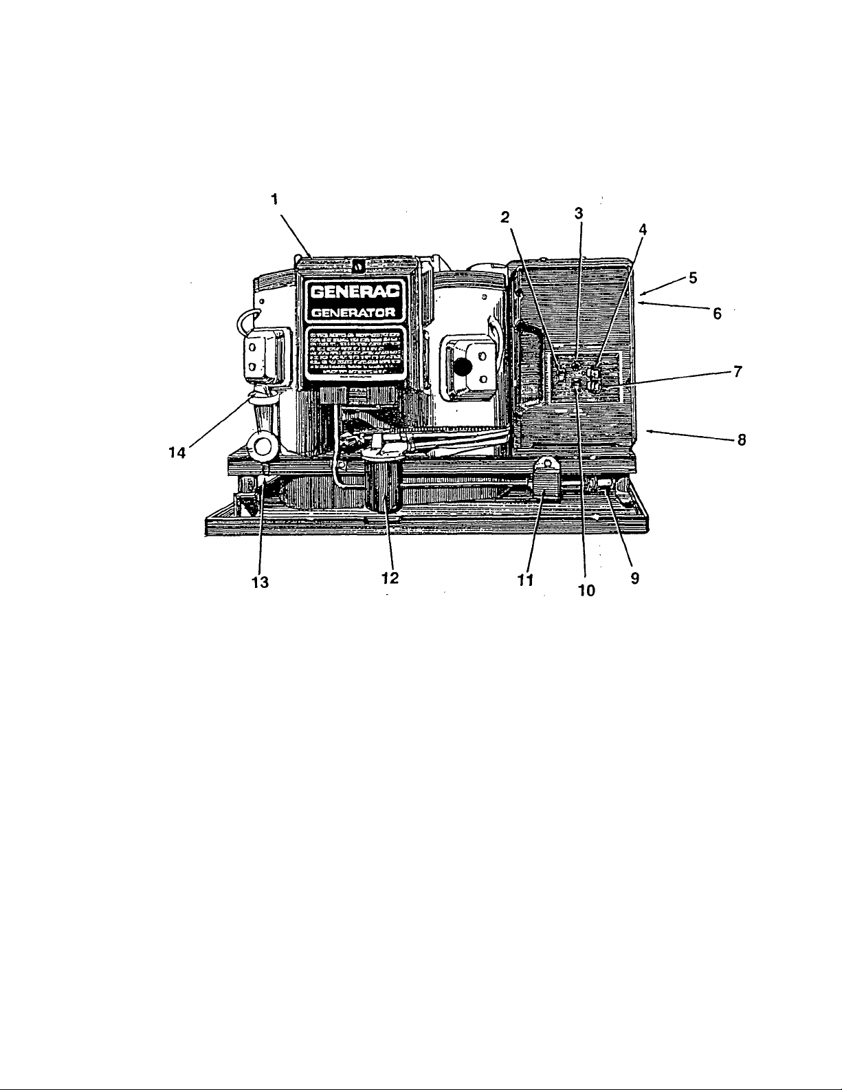
GENERATOR FEATURES
REFERENCE NUMBER IDENTIFICATION
1. Generator Air Intake Screen
2. Engine Start/Stop Switch
3. 15 amp Fuse
4. 20 or 30 amp Circuit Breaker
5. Optional Remote Panel Receptacle
6. Generator AC Output Leads
7. 30 amp Circuit Breaker
8. Starter Contactor
9. Fuel Inlet
10. Fuel Pump Primer Switch
11. Fuel Pump
12. Oil Filter
13. Oil Drain Plug
14. Oil Dipstick and Filler Tube
-4-
Page 7
GENERATOR FAMILIARIZATION
GENERATOR APPLICABILITY
Q-55G and Q-70G generators have been designed and
manufactured for supplying electrical po\wer for recrea
tional vehicles. You should not modify the generator or
use it for any application other than for what it was
designed. If there are any questions pertaining to its
application, write or call the factory. Do not use the unit
until you have been advised by competent authority.
DANGER: FOR FIRE SAFETY, THE GENERATOR
MUST HAVE BEEN PROPERLY INSTALLED IN
COMPLIANCE WITH (1) ANSI 119.2-1975/NFPA
501C-1974 "STANDARD FOR RECREATIONAL
VEHICLES", PART III, "INSTALLATION OF ELEC
TRICAL SYSTEMS." THE GENERATOR ALSO
MUST HAVE BEEN INSTALLED IN STRICT COM
PLIANCE WITH THE MANUFACTURER’S DE
TAILED INSTALLATION INSTRUCTIONS. AFTER
INSTALLATION, DO NOTHING THAT MIGHT
RENDER THE UNIT IN NON-COMPLIANCE WITH
SUCH CODES, STANDARDS AND INSTRUC
TIONS.
You can use your generator set to supply electrical
power for operating one of the following electrical loads:
• Q-55G: 120 and/or 240 volts, single phase, 60 Hz
electrical loads. These loads can require up to 5500
watts (5.5 kW) of power, but cannot exceed 45.8 AC
amperes of current at 120 volts or exceed 22.9 AC
amperes at 240 volts.
• Q-70G: 120 and/or 240 volts, single phase, 60 Hz
electrical loads. These loads can require up to 7000
watts (7.0 kW) of power, but cannot exceed 58.3 AC
amperes of current at 120 volts or exceed 29.1 AC
amperes at 240 volts.
An INSTALLATION MANUAL was shipped with the
generator. That Manual contains manufacturer’s in
structions and recommendations for installing the unit
into an industrial vehicle. After installation, installers
should fonvard the Installation Manual to Owners/Operators for their information.
Owners/Operators have the responsibility to make sure
that nothing is done that might render the installation
unsafe or in non-compliance with applicable codes,
standards and instructions.
SAFETY
Before using the generator set, carefully read GEN
ERAL SAFETY RULES inside the cover. Comply with
these RULES to prevent accidents and damage to
equipment and/or property. Generac suggests copying
and posting the GENERAL SAFETY RULES to potential
operators of this equipment.
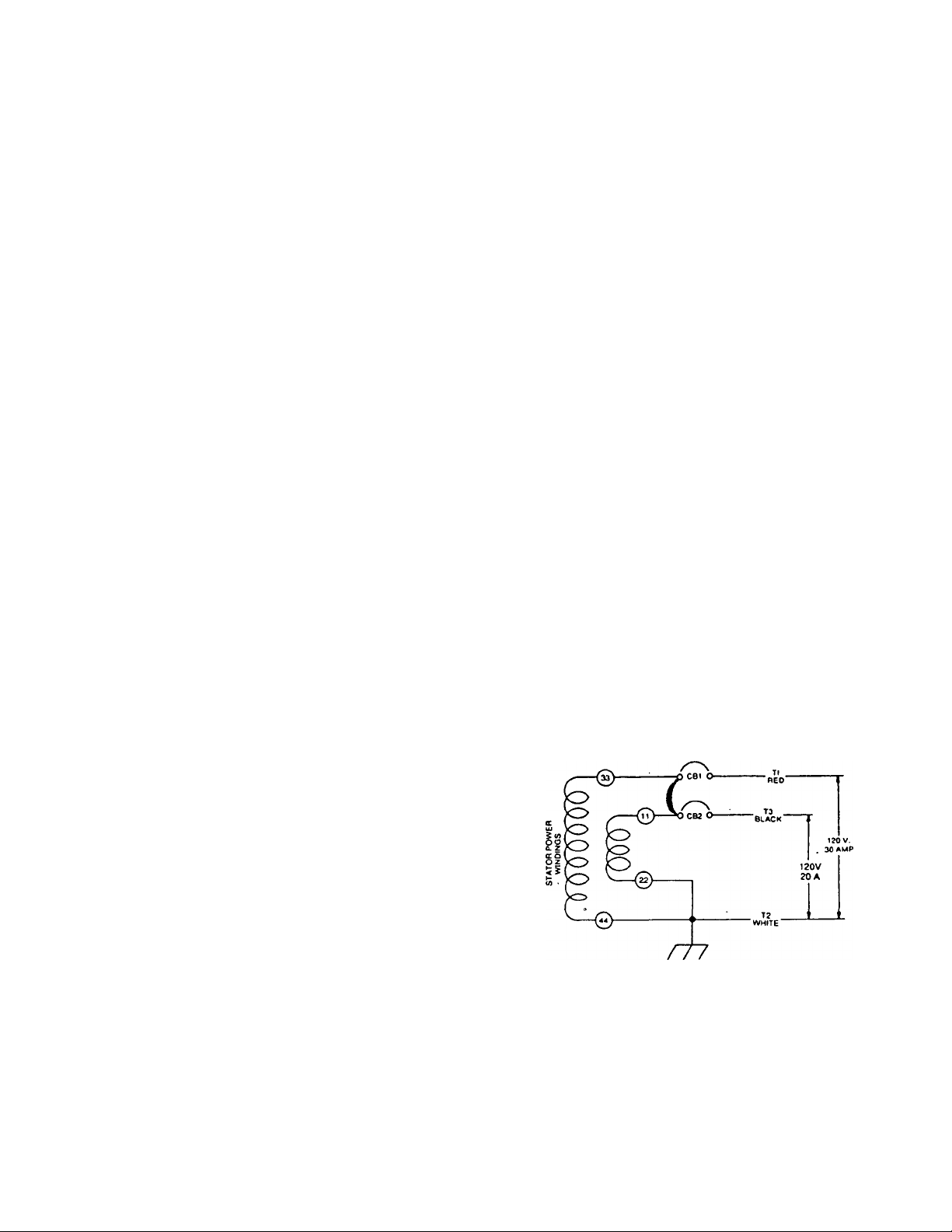
GENERATOR AC CONNECTION SYSTEM
These air-cooled Q Series generator sets are equipped
with dual stator AC power windings. These two stator
windings supply electrical power to customer electrical
loads by means of a dual 2-wire connection system.
The generator may have been installed so that units
only power 120 volts AC loads (Figure 1); or you can
wire them to connect both 120 and/or 240 volts AC
electrical loads. Be sure to remove the jumper between
the circuit breakers when connecting for 120/240 volts.
CAUTION: Do not overload the generator. Some
installations may require that electrical loads be
alternated to avoid overloading. Applying exces
sively high electrical loads may damage the gener
ator and may shorten its life. Add up the rated watts
of all electrical lighting, appliance, tool and motor
loads the generator will power at one time. This
total should not be areater than the wattage capac
ity of the generator. If an electrical device nameplate
gives only volts and amps, multiply volts times
amps to obtain watts (volts x amps = watts). Some
electric motors require more watts of power (or
amps of current) for starting than for continuous
operation.
INSTALLATION
This Owner’s Manual has been prepared under the
assumption that a competent, qualified technician in
stalled the generator into an industrial vehicle. We also
assume the installer complied with all applicable codes,
standards and regulations pertaining to installation.
QROUNOED
NEUTRAL
Figure 1 — Connection for 120 Volts Only
5-
Page 8
OPERATING INSTRUCTIONS
GENERATOR CONTROL PANEL
Mounted on the generator control panel (Figure 2) are
the following features:
• Fuel Pump Primer: Before starting a cold engine
(it has not been started in more than two weeks),
you must press this switch to bring fuel from the tank
to the fuel pump. This rocker type switch springs
back into its original position when you release it.
• Start/Stop Switch: To crank and start the engine,
hold this switch at its START position. Release the
switch when the engine starts. To stop an operating
engine, place the switch in its STOP position. The
switch center position is the RUN position.
• 15 amp Fuse: Protects the engine DC control
circuit against electrical overload. If the fuse ele
ment has melted open due to overloading, the en
gine cannot be cranked. If you must replace it, use
only an identical 15 amp replacement fuse.
• Line Breakers: Protects generator’s AC output
circuit against overload, i.e., prevents unit from
exceeding wattage/amperage capacity. NP-50G
has one 20 amp breaker and one 30 amp breaker.
NOTE: If your "Q" Series generator has been recon
nected for dual voltage AC output (120/240 volts), you
can install line breakers having an amperage rating that
is different than stated above. The replacement line
breakers consist of two separate breakers with a con
necting piece between the breaker handles (so that both
breakers will operate at the same time). If the unit is
reconnected for dual voltage, it is no longer RVIA listed.
START
FUSE
ISA
MAIN
BREAKER
<0
©
GENERAC
RV.
GENERATOR
GEN. RUN
STOP START
Figure 3 — Optional Remote Panel (Model 9042)
AUTOMATIC CHOKE
The engine is equipped with an automatic choke that
consists of two main components—choke solenoid and
prechoke.
Choke Solenoid: During engine cranking (start/stop
switch at START), a solid state choke module signals
the choke solenoid to actuate and cycle (choke
on/choke off) until engine starts. The choke solenoid
thus opens and closes the carburetor choke valve only
when the engine is cranking. When the engine starts,
the choke cycling stops.
Prechoke: The choke system also has a temperature
sensitive metal strip that adjusts the choke valve angle
according to ambient temperatures (i.e. in cold ambient
temperatures the choke valve closes more). Once the
engine starts, an element heats the temperature-sensi
tive strip to a normal operating condition, opening the
choke valve. This may take about 3 minutes in cooler
weather.
jj
STOP
FUEL
PRIMER
Figure 2 — Typical Control Panel
OPTIONAL REMOTE START/STOP PANEL
Optional remote mounted panels are available which
permit you to crank and start the generator from any
convenient location in the industrial vehicle. Figure 3
shows the Model 9042 remote panel which includes (a)
start/stop switch and (b) a generator run lamp.
You can also order Model 9043, a remote panel which
includes the (a) start/stop switch, (b) the generator run
lamp and (c) an hourmeter. The hourmeter provides a
continuous indication of engine-generator operating
time. Use the hourmeter for checking off periodic main
tenance requirements on the unit.
BEFORE STARTING THE ENGINE
IMPORTANT: INSTRUCTIONS AND INFORMATION
IN THIS MANUAL ASSUME THE GENERATOR HAS
BEEN PROPERLY INSTALLED, CONNECTED, SER
VICED, TESTED AND ADJUSTED BY A OUALIFIED
INSTALLATION TECHNICIAN OR INSTALLATION
CONTRACTOR.
• Installation: Generator installation must have
been properly completed so it complies with all
applicable codes, standards and regulations and
with the manufacturer’s recommendations.
• Engine Lubrication: Have engine crankcase
properly serviced with recommended oil before
starting. Refer to "Maintenance“ and "Specifica
tions” sections for oil servicing procedures and rec
ommendations.
CAUTION: Any attempt to crank or start the engine
before you have properiy serviced it with the recom
mended oii will result in an engine failure.
-6-
Page 9

Fuel Supply: The engine must have adequate
supply of proper fuel to operate. Before starting,
check that sufficient fuel is available.
NOTE: On some installations, the generator en
gine may “share" the vehicle’s gasoline fuel tank
with vehicle engine. Some installations may pro
vide separate fuel tanks for generator and vehicle
engine.
Cooling and Ventilating Air: Air inlet and outlet
openings in the generator compartment must be
open and unobstructed for continued proper oper
ation. Without sufficient cooling and ventilating air
flow, the engine-generator quickly overheats which
causes it to quickly shutdown. Overheating could
also damage the unit or your vehicle.
Engine Exhaust Gases: Before starting the gen
erator engine, you should be sure there is no way
for exhaust gases to enter the vehicle interior and
endangering people or animals. Close windows,
doors and other openings in the vehicle that, if open,
might permit exhaust gases to enter the vehicle.
DANGER: THE GENERATOR ENGINE GIVES
OFF DEADLY CARBON MONOXIDE GAS
THROUGH ITS EXHAUST SYSTEM. THIS DAN
GEROUS GAS, IF BREATHED IN SUFFICIENT
CONCENTRATIONS, CAN CAUSE UNCON
SCIOUSNESS OR EVEN DEATH. DO NOT OPER
ATE THE GENERATOR IF ITS EXHAUST SYSTEM
IS LEAKING OR HAS BEEN DAMAGED. SYMP
TOMS OF CARBON MONOXIDE POISONING ARE
(A) INABILITY TO THINK COHERENTLY, (B)
VOMITTING, (C) TWITCHING MUSCLES, (D)
THROBBING TEMPLES, (E) DIZZINESS, (F)
HEADACHE, (G) WEAKNESS AND SLEEPINESS.
IF YOU FEEL ANY OF THESE SYMPTOMS, MOVE
INTO FRESH AIR IMMEDIATELY. IF SYMPTOMS
PERSIST, GET MEDICAL HELP.
STARTING
IMPORT ANT: Read the vehicle manufacturer’s instruc
tions. The owner/operator should become familiar with
the vehicle in which this generator is installed. Differ
ences exist between vehicles. For example, some ve
hicles may use a transfer switch to isolate dockside
power from the generator, while other vehicles may use
an isolating receptacle. Some vehicles may be
equipped with a DC converter which allows the gener
ator to power certain DC lighting and other DC loads.
To crank and start the generator engine, proceed as
follows;
1. Turn CFF electrical loads, using whatever means
provided in your vehicle (such as a main line circuit
breaker or transfer switch.
NOTE: If you start the engine with start/stop switch on
the generator control panel, turn CFF loads by setting
the panel’s main breakers to their "CFF“ or “CPEN"
positions. Electrical load circuits will be turned CN after
the generator has started, stabilized and warmed up.
2. If you have not started the engine in more than two
weeks, press the Fuel Pump Primer switch and hold
it for about 30 seconds to activate the automatic
shut-off function. However, if the engine is warm,
skip Step 2.
3. To crank and start the engine, hold the start/stop
switch at START. Release the switch when the
engine starts.
CAUTION: If the engine does not start after it has
been cranking for 15 seconds, release the start/stop
switch and try again. Holding the switch for longer
than 15 seconds can damage the starter motor.
4. Let the engine run at no-load for a few minutes to
stabilize and warm up the engine.
5. Turn CN electrical loads, using whatever means
provided (such as a main circuit breaker or transfer
switch).
STOPPING THE GENERATOR
1. Turn CFF all electrical loads, using whatever
means provided (such a main circuit breaker or
transfer switch).
2. Let the generator run at no-load for a few minutes,
to stabilize internal engine-generator tempera
tures.
3. Press STCP on the start/stop switch. The engine
will come to complete stop.
APPLYING LOADS TO GENERATOR
When applying electrical loads to the generator, ob
serve these guidelines:
• Before applying electrical loads, let the generator
stabilize and warm up for a minute or two.
• DC NCT overload the generator.
Letting Engine Stabilize: The generator supplies cor
rect rated frequency and voltage only at the proper
governed speed. Some electrical appliances may be
extremely sensitive to voltage and frequency. Incorrect
frequencies and/or voltages can damage those appli
ances.
If electrical loads are applied at reduced operating
speeds, such loads imposed on the engine when suffi
cient power is not available may shorten engine life.
Never turn CN electrical loads until after the generator
engine has started and stabilized CN-speed.
-7-
Page 10

Do Not Overload the Generator: You can read the
rated wattage/amperage capacity of your generator on
the generator data plate (see 'Identification Record" on
Page 1).
Applying electrical loads in excess of the unit’s rated
capacity can bum out the unit and anything connected
to it. Also, overloading trips main circuit breakers.
To avoid overloading, add up the wattage of all con
nected electrical lighting, appliance, tool and motor
loads. This total should not be greater than the
generator’s rated wattage capacity.
• Most lighting, appliance, tool and motor loads indi
cate their reouired watts on their nameplate or data
plate. For light bulbs, simply note the wattage rating
of the bulb.
WATTAGE REFERENCE GUIDE
If a load does not show its rated wattage, multiply
that load’s rated VOLTS times AMPS to obtain
WATTS.
Induction type motors (such as those that run the
vehicie’s furnace fan, refrigerator, air conditioner,
etc.) need about 2-1/2 times more watts of power
for starting than for running (for a few seconds
during motor starting). Be sure to allow for this
when connecting electrical loads to the generator.
Rrst, figure the watts needed to start electric motors
in the system. To that figure, add the running
wattages of other items that will be operated by the
generator.
Do not apply heavy electrical loads for the first two
or three hours of operation.
RUNNING
WATTS
*Air Conditioner (12,000 Btu)
Battery Charger (20 amp)
.................................
.......................................
1700
500
Belt Sander (3').......................................................1000
Chain Saw
Circular Saw (6-12/")
..............................................................
....................................
800 to 1000
1200
Coffee Maker..........................................................1000
‘Compressor (1 HP)
...............................................
2000
‘Compressor (3/4 HP).............................................1800
‘Compressor (1/2 HP).....................................^
......
1400
Curling Iron...............................................................700
‘Deep Freeze............................................................500
Disc Sander (9").....................................................1200
Edge Trimmer...........................................................500
Electric Nail Gun
Electric Range (one element)
Electric Skillet
....................................................
................................
....................:....................................
1200
1500
1250
‘Furnace Fan (1/3 HP)............................................1200
Hair Dryer...............................................................1200
Hand Drill (Г)
Hand Drill (1/2')
..........................................................
...........................................
750 to 1000
1100
Hand Drill (3/8")........................................................500
Hand Drill (1/4")...................................................... 250
Hedge Trimmer
Impact Wrench
‘Jet Pump
........................................................
.........................................................
.................................................................
450
500
800
RUNNING
WATTS
Lawn Mower
Light Bulb.......................................................................100
Microwave Oven............................................................700
‘Milk Cooler..................................................................1100
Oil Burner on Furnace
Oil Rred Space Heater (140,000 Btu)............................400
Oil Rred Space Heater (85,000 Btu)..............................225
Oil Rred Space Heater (30,000 Btu)..............................150
‘Paint Sprayer, Airless (1/3 HP).....................................600
Paint Sprayer, Airless (handheld)..................................150
Radio...................................................................
‘Refrigerator
Slow Cooker..................................................................200
‘Submersible Pump (1-1/2 HP)....................................2800
‘Submersible Pump (1 HP)
‘Submersible Pump (1/2 HP).......................................1500
Sump Pump...................................................................600
‘Table Saw (10")
Television
Weed Trimmer................................................................500
‘ Allow 2-1/2 times the listed watts for starting these
devices.
..............................................................
...................................................
................................;.................................
......
....................................2000
.........................
..........................................................
.................
1750 to 2000
200 to 500
1200
300
50 to 200
600
-8-
Page 11
This section discusses some of the engine protective
devices, overload protection and breaking in a new
generator.
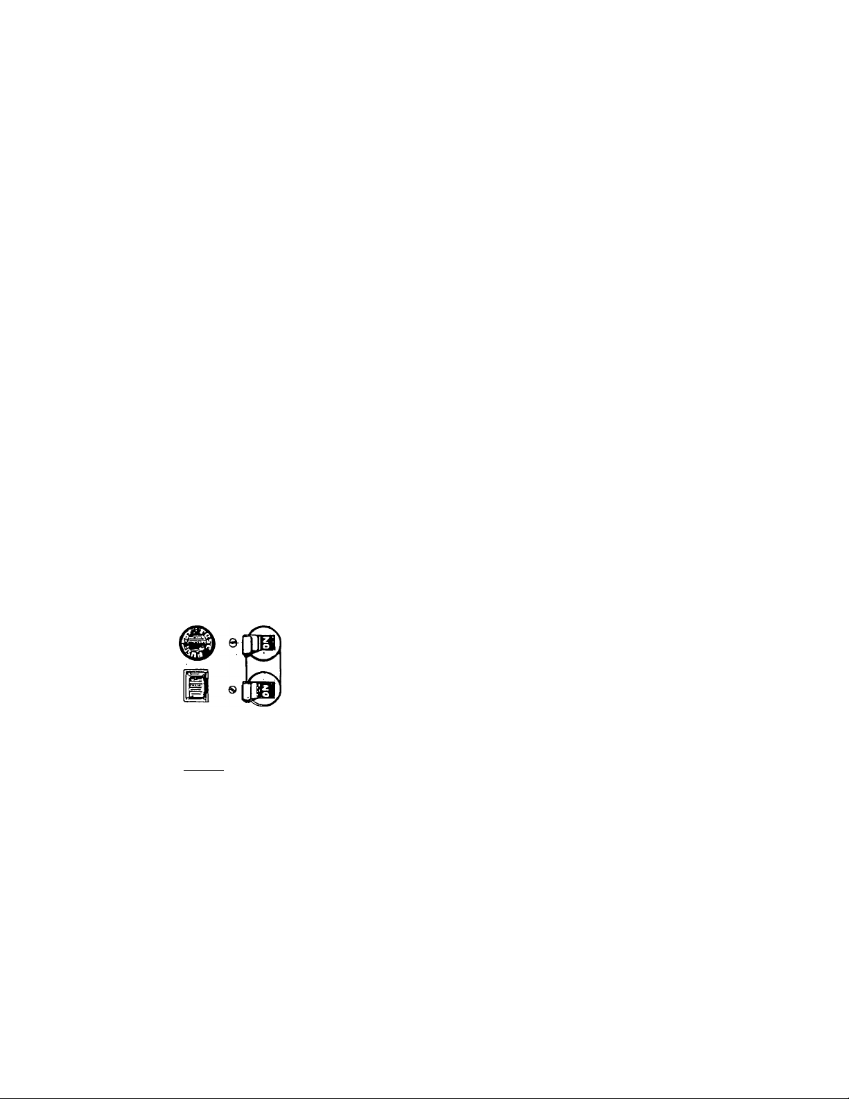
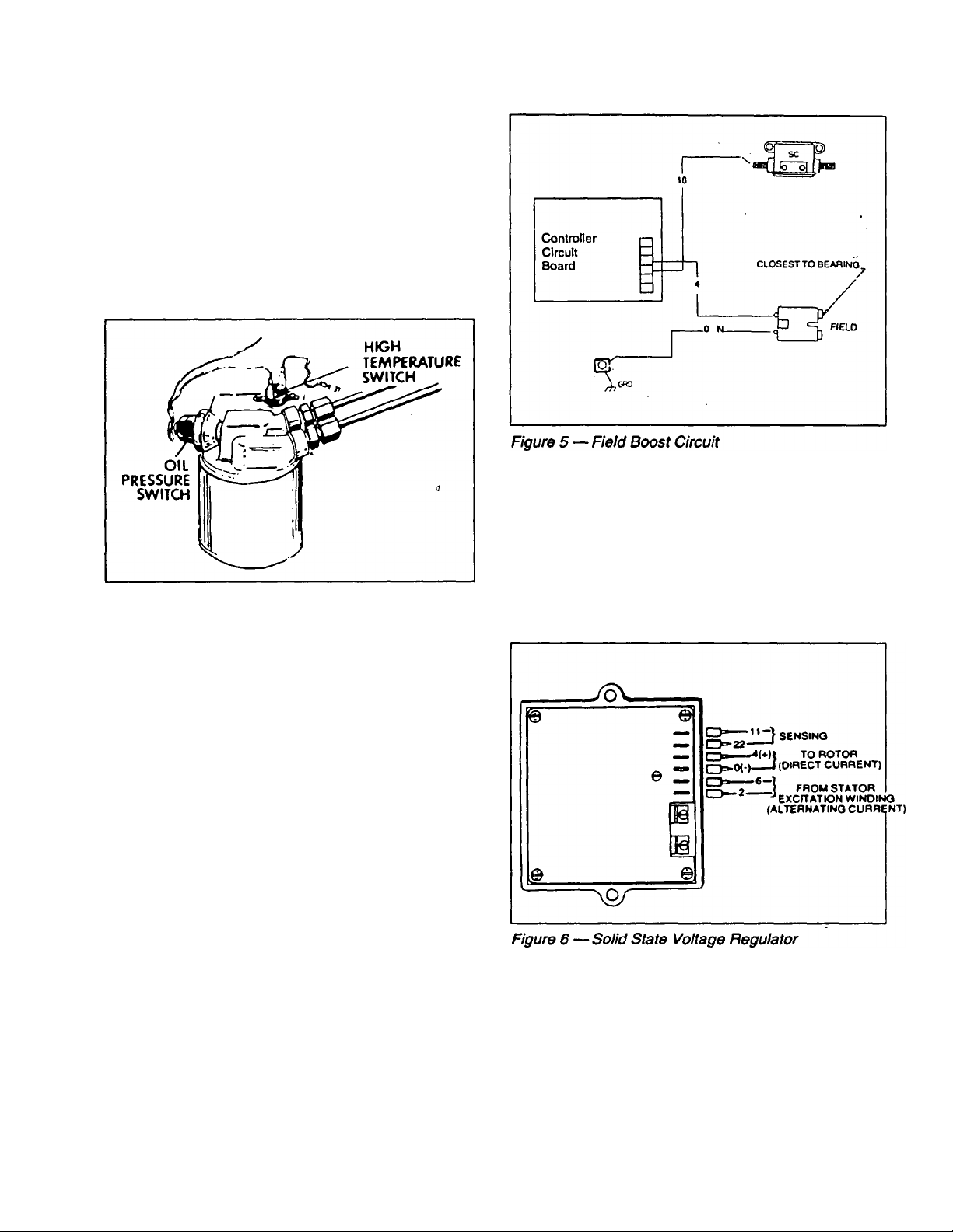
AUTOMATIC LOW OIL PRESSURE
SHUTDOWN
The engine is equipped with a normally-closed (N.C.)
oil pressure switch (Figure 4). Engine oil pressure holds
the switch open during cranking and operation. Should
oil pressure drop below about 2-6 PSI, the switch con
tacts close and the engine automatcially shuts down.
Figure 4 — Switches for Enghe Safety Shutdown
ADDITIONAL INFORMATION
OVER VOLTAGE PROTECTION
A solid state voltage regulator (Rgure 6) controls the
generator’s AC output voltage. This regulator supplies
an excitation current to the rotor. By regulating the
rotor’s excitation current, the strength of its magnetic
field is regulated and, in turn, the voltage delivered to
connected electricaJ loads is controlled. When the AC
frequency is 60 Hz, voltage is regulated at 120 volts
(voltage-to-frequency ratio is 2-to-1).
HIGH TEMPERATURE SHUTDOWN
An oil temperature switch (Figure 4) with normally-open
(N.O.) contacts is mounted near the oil filter. If oil
temperature were to exceed about 284®F (140“C), the
switch contacts close and the engine shuts down.
FIELD BOOST
The Controller Circuit Board houses a field boost diode
and resistor which are not part of the automatic choke
circuit. These two components are part of a "field boost"
circuit (Figure 5). During engine cranking only, a posi
tive DC (battery) voltage is delivered through the diode,
resistor, brushes and slip rings, and to the generator
rotor. Application of this voltage to the rotor "flashes the
field’ whenever it is started. Hashing of the field each
time the generator starts makes sure that a sufficiently
strong magnetic field is available to produce the re
quired "pick up" voltage in the stator windings.
The voltage regulator also incorporates a "voltage surge
protection circuit." This circuit prevents troublesome
surges in the generator AC ou^ut voltage. Voltage
surge is a common cause of damage to electronic
equipment.
-9-
Page 12

25-HOUR BREAK IN PERIOD
The first 25 hours of operation are for “breaking in" the
new generator. Correctly breaking in the generator is
essential to minimize fuel consumption and provide
maximum engine performance. During this 25-hour
break in period, comply with the following:
• Run the unit at varying electrical loads, to help seat
engine piston rings properly.
• For the 75 hours of operation after the “break in“
period, avoid light electrical loads. Load the gener?
ator at 50% (or more) of its rated wattage capacity.
Repeated light loads during the break in period can
cause improper seating of engine piston rings,
which could cause blowby and high oil consump
tion.
• During the break in period, check engine oil level
frequently. It is normal for oil consumption to be
high during the breaking in period.
• After the 25-hour break-in period, complete the
tasks recommended under “25-Hour Check Up.“
25-HOUR CHECK UP
After the 25-hour break-in period, contact an authorized
service facility for the following maintenance. The vehi
cle owner is responsible for any charges:
Change engine crankcase oil and oil filter.
Check all fluid levels.
Inspect cooling and ventilation openings on the
vehicle.
Check engine carburetor adjustments.
Check engine ignition system.
Inspect entire electrical system.
Inspect the engine exhaust system.
OPERATION IN HIGH GRASS OR BRUSH
Never operate the generator while the vehicle is parked
in high grass, weeds, brush or leaves. Such materials
can ignite and bum from the heat of the exhaust system.
The generator exhaust systern becomes extremely hot
during operation and remains hot for a long time after it
has shut down.
-10-
Page 13

_________
SPECIFICATIONS
FUEL REQUIREMENTS
The “Q“ series generator is equipped with a gasoline
fuel system as standard equipment. Specific installa
tions may provide either a separate fuel tank for the
generator, of the generator may “share“ the vehicle
engine’s fuel tank.
NOTE: Some installations using a “shared“ fuel tank
may have a generator fuel pickup tube that is shorter
than the vehicle engine’s pickup tube. Such an arrange
ment causes the generator engine to “run out of gas“
while adequate fuel in the vehicle remains in the tank.
To reduce lead and carbon deposits use high quality
UNLEADED gasoline with the generator. Leaded REG
ULAR grade gasoline is an acceptable substitute.
NOTE: Using “Unleaded“ gasoline contributes to
longer engine valve life by reducing lead and carbon
deposits.
CAUTION: Generac does not recommend using any
gasoline containing alcohol (such as “gasohor). If
you use any gasoline containing alcohol, it must not
contain more than 10 percent ethanol and It must be
removed from the tank during storage. Do NOT use
any gasoline containing methanol. If you use gas
oline with alcohol, Inspect more frequently for fuel
leaks and other abnormalities.
ENGINE OIL REQUIREMENTS
Use a high quality detergent oil classified "For Service
SF“ and with an oil viscosity rating of SAE 10W-30 oil.
Do not pour in any additives to the recommended oil.
Engine crankcase capacity is 1.5 U.S. quarts. See
MAINTENANCE section for oil level check and filling
procedures.
ENGINE SPECIFICATIONS
Type of Engine
Q-55G
........................................
Q-70G
........................................
Cooling Method............................Air-cooled
Rated Horsepower
Q-55G
........................................
Q-70G
........................................
Displacement
Q-55G
.......................................
Q-70G......................................570CC
Compression Ratio
Cylinder Block
Type of Governor
Engine Governed Speed
Air Cleaner............
Starter
..........................................
Ignition System
......................
..............................
.........................
............
.....................
..............................
Recommended Spark Plugs
Champion
AC
........................................
..................................
Pram Autolite............................65
Spark Plug Gap.......................... 0.030 inch (0.8mm)
GN-480
GN-570
15 at 3600
18at3600rpm v
480cc
8.6 to 1
Aluminum with cast
iron sleeve
Mechanical, fixed
speed
2500 rpm
Paper element with
foam pre-cleaner
12 volts DC electric
Solid state with
flywheel magneto
RC12YC
.....R45S
GENERATOR SPECIFICATIONS
SERIES
Rotor RPM
Rotor Poles 2 2
Engine RPM
Rated Max. Continous AC Output* 5500 watts (5.5 kW)
Voltage* 120 120
Rated Max. Continuous Current*
1 Phase
Frequency
Weight 215 pounds
Length
Width 18.5 inches
Height 15.75 inches
* All units are reconnectable to 120 and/or 240 volts, dual voltage output. Units are not listed per RVIA/ANSI when
reconnected for dual voltage output.
t Rated maximum continuous current at 240 volts is 22.9 amps.
V Rated maximum continuous current at 240 volts is 29.1 amps.
Q-55G
3600 3600
2500
7000 watts (7.0 kW)
45.8 AC ampst
1
60 Hertz
25 inches 25 inches
-77-
58.3 AC ampsV
60 Hertz
222 pounds
18.5 inches
Q-70G I
2500
1
15.75 inches 1
Page 14

MAINTENANCE
This section includes information about simple mainte
nance which includes the following tasks:
Checking engine oil level.
Changing engine oil.
Changing oil filter.
Changing the air cleaner.
Cleaning the air intake screen.
Cleaning spark plugs.
CHECKING ENGINE OIL LEVEL
Check engine crankcase oil level at least every eight
hours of operation, or before you use it (Figure 7).
Figure 8 — Location of Oil Drain Plug
• Remove oil dipstick and fill crankcase with the rec
ommended oil (See Page 11). The engine crank
case can hold about 1.7 liters. DO NOT OVERFILL
ABOVE "FULL" MARK.
• Install and tighten dipstick cap before operating
engine.
Figure 7 — Oil Dipstick and Fill Tube
• Be sure the generator is as level as possible.
• Remove oil dipstick and wipe dry with clean, lint-free
cloth.
• Install and tighten oil dipstick, then remove again.
• Oil should be at dipstick FULL mark. If necessary,
add the recommended oil to the FULL mark only.
DO NOT OVERFILL ABOVE “FULL" MARK.
• Install and tighten oil dipstick cap before operating
the engine.
NOTE: See "Engine Oil Requirements" on Page 11 for
recommended oils.
CHANGE ENGINE OIL
Change engine oil after the first 25 hours of operation
(after the 25-hour break-in period. Page 10). Thereaf
ter, change oil every 50 operating hours. Change oil
more frequently if operating consistently under heavy
load or at high ambient temperatures.
• Warm up engine for at least five minutes, then shut
down.
• With engine still warm from running, remove oil
drain plug (Figure 8). Drain oil completely into a
suitable container.
• When oil has drained, install and tighten oil drain
plug.
CHANGE OIL FILTER
Replace the engine oil filter after the first 25 hours of
operation, every 100 operating hours thereafter.
• Turn oil filter counterclockwise to remove (Figure 9).
• Coat gasket of new filter with engine oil.
• Turn new filter clockwise until its gasket contacts
tightly with the filter adapter. Then tighten with an
additional 3/4 to one turn by hand.
• Run engine and check for leaks.
-72-
Page 15
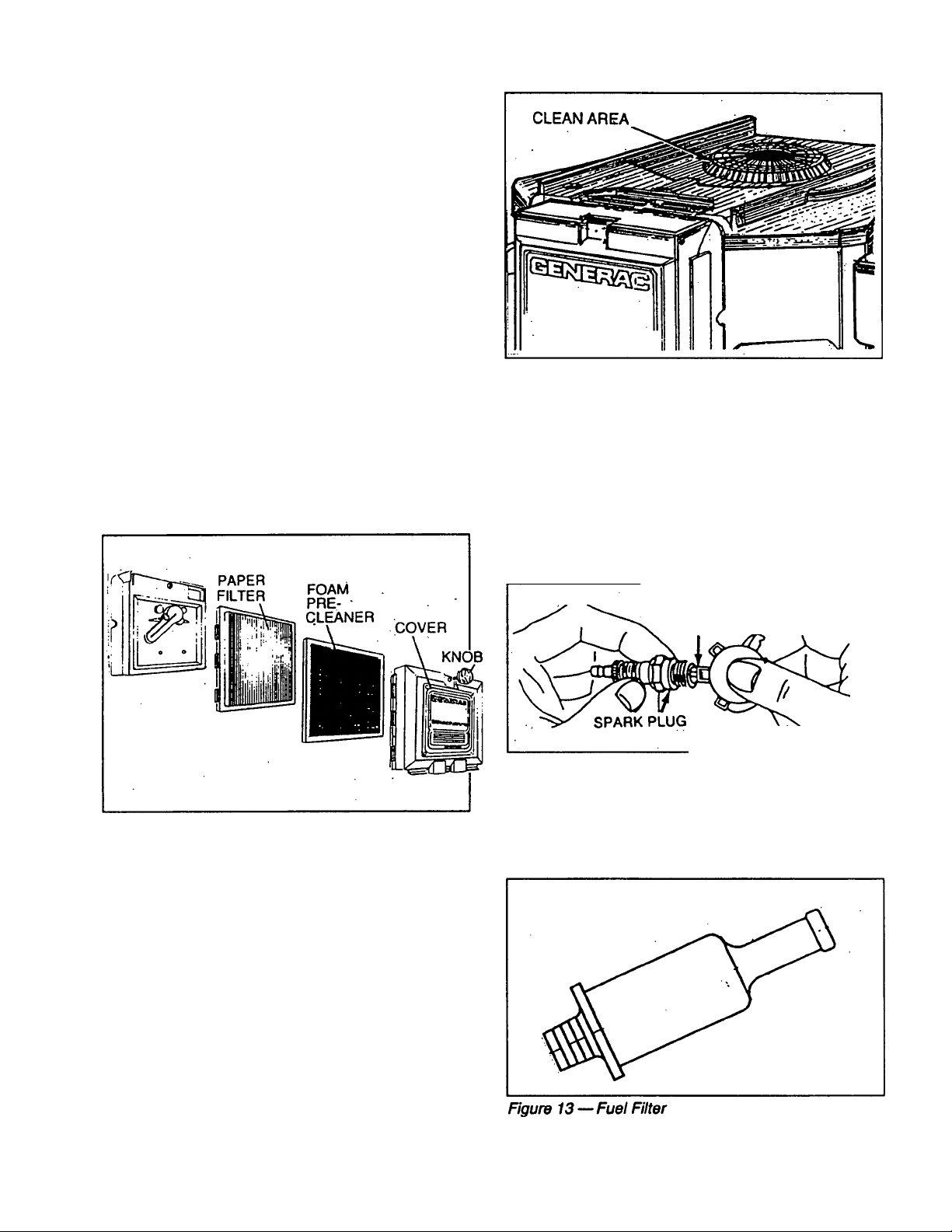
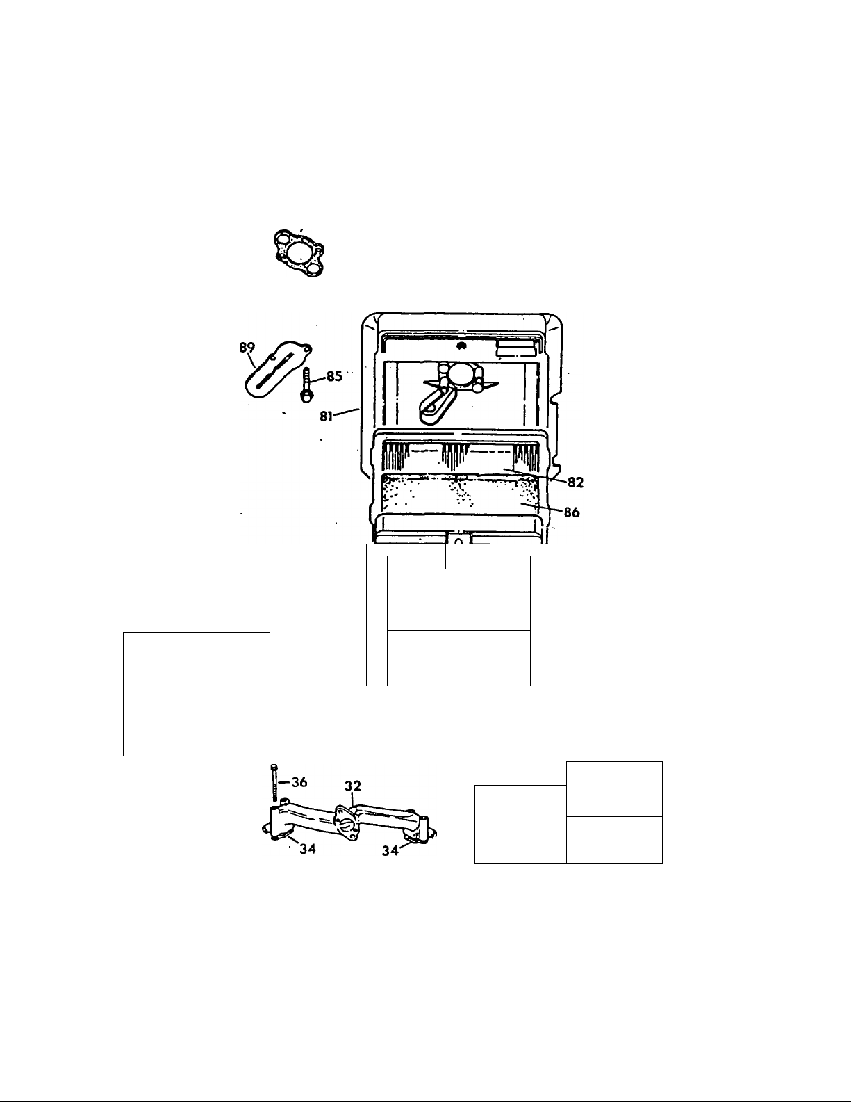
ENGINE AIR CLEANER
Clean and re-oil the foam pre-cleaner every three
months or every 25 hours of operation; whichever oc
curs first. Sen/ice the foam pre^eaner more frequentiy
if you operate the generator in extremely dusty or dirty
conditions (Figure 10):
• Turn KNOB counterclockwise to loosen.
• Remove COVER, FOAM PRE-CLEANER and
PAPER RLTER.
• Remove foam pre-cleaner from cover.
• Wash foam pre-cleaner in liquid detergent and
water.
• Wrap foam pre-cleaner in a cloth and squeeze dry.
• Saturate foam pre-cleaner in engine oil. Squeeze
to remove excess oil and to distribute oil.
• Install foam pre-cleaner into cover, followed by
filter. Tabs at edges of paper filter must lock
ots on cover.
K
• Insert bottom locking tag of cover into slot. Install
cover, foam pre-cleaner and paper filter.
Once each year or every 100 operating hours (which
ever comes first), replace the paper filter. The new
replacement filter must be a flame retardent type.
Figure 11 — Areas to Clean on Air Intake Screen
ENGINE SPARK PLUGS
Clean engine spark plugs and reset gap to 0.030 inch
(0.8mm) every 100 hours of operation (Figure 12).
Clean by scraping or wire brushing and washing with
commercial solvent DO NOT BLAST CLEAN SPARK
PLUGS.
CAUTION: Sparking can occur If wire terminals do
not fit firmly over spark plug terminal ends. If nec
essary, reform wire terminals to obtain a tight fit.
Figure 10 — Engine Air Cleaner
CLEAN AIR INTAKE SCREEN
Clean all foreign material from the air intake screen
(Rgure 11) at least once every 100 hours of operation.
Clean more often, if necessary.
Inspect the area around the generator exhaust muffler
periodically and remove all grass, leaves, dirt, etc. from
this area.
030" (.76 mm)
FEELER GAUGE'
Figure 12 — Setting Spark Plug Gap
FUEL FILTER
Remove and replace fuel filter (Rgure 13) every 100
hours of operation or once each year, whichever comes
first.
■ 13-
Page 16

MISCELLANEOUS MAINTENANCE
SPARK ARRESTOR MUFFLERS
If the generator is not equipped with a spark arrestor
exhaust muffler and is to be used on any forest covered,
brush covered or grass covered unimproved land, you
may have to install a spark arrestor. The spark arrestor
must be maintained in effective working order by the
vehicle owner/operator.
For assistance in ordering, installing and maintaining
spark arrestor exhaust mufflers, contact your nearest
authorized service facility.
Exhaust mufflers supplied by Generac are spark arres
tor types. Generac exhaust mufflers for RV generators
do not have a spark arrestor screen, but are of the more
efficient "toroid” or “swirl" type. To remove carbon and
combustion deposits from such mufflers, remove the
PLUG from muffler and run engine for about 15 minutes.
Shut engine down, let the muffler cool and install the
plug.
WARNING: BE SURE TO RE-INSTALL THE PLUG
FROM THE MUFFLER TIGHTLY. ENGINE VIBRA
TION COULD CAUSE A LOOSE PLUG TO FALL
OUT. WITHOUT THE PLUG IN PLACE, HOT EN
GINE EXHAUST IS DIRECTED OUT THE OPEN
ING. THIS HOT EXHAUST, DEPENDING ON THE
INSTALLATION, COULD BE DIRECTED TO
AREAS NOT ABLE TO WITHSTAND THE EX
TREME HEAT SUCH AS WOODEN FLOOR
BOARDS OR OTHER FLAMMABLE MATERIALS.
THIS COULD RESULT IN A FIRE.
CLEANING THE GENERATOR
Keep your generator set as clean and dry as possible.
Dirt and moisture that are permitted to accumuiate on
electrical windings have an adverse affect on the insu
lation resistance of those windings.
Moisture that is allowed to remain in contact with wind
ings will be retained in voids and cracks of the windings.
Dirt makes the problem worse, since it tends to hold the
moisture into contact with the windings. Salt, as from
sea air, worsens the problem since it tends to absorb
moisture from the air. The combination of salt and
moisture makes a good electrical conductor.
CAUTION! Do NOT use a forceful spray of water to
clean the generator. Water will enter the generator
Interior and cause problems, and may also contam
inate the generator fuel system.
All lead-acid storage batteries will discharge when not
in use. The generator battery should be inspected as
follows:
Once Weekly: Inspect battery posts and cables for
tightness, corrosion. Clean and/or tighten as needed.
Also check battery fluid level, and, if necessary, fill with
DISTILLED WATER ONLY. DO NOT USE TAP
WATER IN BATTERY.
Every Six Months: Have battery state of charge and
condition checked by automotive service facility. This
should be done with automotive type battery hydrome
ter.
DANGER: STORAGE BATTERIES GIVE OFF EX
PLOSIVE HYDROGEN GAS. THIS GAS CAN
FORM AN EXPLOSIVE MIXTURE AROUND THE
BATTERY FOR SEVERAL HOURS AFTER
CHARGING. THE SLIGHTEST SPARK CAN IG
NITE THE GAS AND CAUSE AN EXPLOSION.
SUCH AN EXPLOSION CAN SHATTER THE BAT
TERY AND CAUSE BLINDNESS OR OTHER IN
JURY. ANY AREA THAT HOUSES A STORAGE
BATTERY MUST BE PROPERLY VENTILATED.
DO NOT ALLOW SMOKING, OPEN FLAME,
SPARKS OR ANY SPARK PRODUCING TOOLS
OR EQUIPMENT NEAR THE BATTERY.
DANGER: BATTERY ELECTROLYTE FLUID IS
AN EXTREMELY CAUSTIC SULFURIC ACID SO
LUTION THAT CAN CAUSE SEVERE BURNS. DO
NOT PERMIT FLUID TO CONTACT EYES, SKIN,
CLOTHING, PAINTED SURFACES, ETC. WEAR
PROTECTIVE GOGGLES, PROTECTIVE CLOTH
ING AND GLOVES WHEN HANDLING A BAT
TERY. IF YOU SPILL THE FLUID, FLUSH THE
AFFECTED AREA IMMEDIATELY WITH CLEAR
WATER.
DANGER: DO NOT USE ANY JUMPER CABLES
OR BOOSTER BATTERY TO CRANK AND START
THE GENERATOR ENGINE. IF ANY BATTERY
HAS DISCHARGED, REMOVE IT FROM THE VE
HICLE FOR RECHARGING.
To obtain a sen/ice manual for your generator, order it
from your dealer/distributor or contact the factory. Be
sure to identify your MODEL NUMBER and SERIES.
BATTERY
MAJOR SERVICE MANUAL
-14-
Page 17

DRIVE BELTS
The engine drives the generator rotor by means of a
pulley and drive belt arrangement. The drive train, drive
belt and pulleys are warranted for the life of the gener
ator. Drive belt tension was properly adjusted before
the unit was shipped from the factory. If you suspect
that drive belt tension is incorrect, contact an authorized
service facility.
Remove spark plugs and pour about two or three
tablespoons of clean, fresh, engine oil into spark
plug threaded openings. Crank engine several
times to distribute oil, then install and tighten spark
plugs.
Remove the battery and store in a cool, dry room
on a wooden board. Never store the battery on any
concrete or wooden floor.
Clean and wipe the entire generator.
EXERCISING THE GENERATOR
Generac recommends that you start and operate the
generator at least once every seven days. Let the unit
run for at least 30 minutes to "exercise” the engine.
OUT OF SERVICE PROTECTION
If you cannot exercise the generator every seven days
and it is to be out of service longer than 30 days, prepare
the.generator for storage as follows:
• Start the engine and let it warm up.
• Close the fuel shutoff valve in the fuel supply line
and let the engine “run out of gas."
• While the engine is still warm from running, drain
the oil completely. Refill crankcase with SAE10W30 oil having API classification "For Service SF."
• Attach a tag to the engine indicating the viscosity
and classification of the oil in the crankcase.
RETURN THE UNIT TO SERVICE AFTER
STORAGE
To return the unit to service after storage, proceed as
follows:
• Check tag on engine for oil viscosity and classifica
tion. Verify that the correct recommended oil is
used in engine. If necessary, drain and refill with
proper oil.
• Check battery. Fill all cells to the proper level with
distilled water. DO NOT USE TAP WATER IN THE
BATTERY. Recharge battery to 100% state of
charge, or, if defective, replace the battery.
• Turn OFF all electrical loads, add gasoline if neces
sary; then start the engine.
• Let engine warm up.
• Apply electrical loads to at least 50% of the unit’s
rated wattage capacity.
• When engine is thoroughly warmed up, shut it
down.
THE GENERATOR IS NOW READY FOR SERVICE.
-15-
Page 18

TROUBLESHOOTING
PROBLEM POSSIBLE CAUSE(S) REMEDY
Engine won’t crank 1. 15 amp fuse blown.
2. Loose, corroded or defective battery
cable(s).
3. Battery is discharged or defective.
4. Defective starter contactor.
5. Defective starter motor.
6. Defective control relay (CR1).
Engine cranks, won’t start
1. Out of fuel.
2. Fuel shutoff valve is closed.
3. Fuel pump not operating.
4. Automatic choke not operating
properly.
5. Engine is flooded.
6. Fuel filter is clogged.
7. Defective control relay (CR2).
8. Engine spark plugs defective.
9. Bad ignition magneto on engine.
10. Bad carburetor.
11. Dirty air cleaner.
Engine starts hard, runs rough.
1. Dirty engine air cleaner.
2. Automatic choke is sticking.
3. Defective spark plugs.
4. Defective ignition magneto.
1. Replace blown fuse.
2. Tighten, clean or replace, as
necessary.
3. Recharge or replace battery.
4. Replace starter contactor.
5. Replace starter motor.
6. Replace control relay.
1. Refill fuel tank.
2. Open fuel shutoff valve(s).
3. Repair or replace pump.
4. Repair, replace or adjust.
5. Wart 5t1 0 minutes: try again.
6. Replace filter if clogged.
7. Replace bad relay (CR2).
8. Clean, regap or replace as needed.
9. Replace if defective.
10. Adjust, repair or replace.
11. Clean or replace as needed.
1. Clean or replace as needed.
2. Free choke linkage as needed.
3. Clean, regap or replace.
4. Replace it if defective.
Engine starts, then shuts down.
No AC output voltage
1. Engine oil level is low
2. Bad control relay (CR1).
3. Bad low oil pressure switch.
4. Bad control relay (CR2).
5. Water in fuel.
1. Main breaker(s) open.
2. Transfer switch (if so equipped)
is set to wrong position.
3. Failure in vehicle electrical system.
4. Generator component failure.
1 Add oil as needed.
2. Replace if bad (CR1).
3. Replace, If bad.
4. Replace bad relay (CR2).
5. Drain fuel tank and refill.
1. Close main breaker(s).
2. Reset transfer switch.
3. See vehicle manual.
4. Contact authorized service facility.
-16-
Page 19

ELECTRICAL DATA
-17-
Page 20
EXPLODED VIEW — SHEET METAL
Drawing No. 89403
-18-
Page 21

REPAIR PARTS LIST — ENGINE SHEET METAL
Drawing No. 89403
ITEM PART NO. QTY. DESCRIPTION
1
67877
2
67198-N
3
4
67890
5 87865
7 86313
8 56893
10 87750
11
12 74908
13
14
15
16 74902
17
19
20
21
22 75246
23
24 74900
25
26 81108
27 22717-B
28
29 67866
30 77001
31 73132
33
34
35
36
74916
73190
78858
78859
66476
73191
42907 2
22129
10-74260
73186
22717-A 3 Rubber Grommet
87858A 1 Ground Wire Assembly — #2 cyl.
29289
87858B 1 Ground Wire /Assembly — #1 cyl.
50277
1 See Engine Expioded View
1 6 X 25 Woodruff Key
1
1
1 Flywheel Access Plug
1 Engine Housing Top
23
1
1
9
1 No. 2 Cylinder Wrapper
1 Valley Cover
1
2
2 M6-1.00 X12mm Capscrew with lock washer
1
2
4
1 No. 16 Wire Assembly
1
1 Crankcase Wrapper
1 Snap Bushing
1 Rubber Grommet
1
1
2 Spark Plug Boot
2 ft.
1 Oil Drain Decal
Belleville Washer
M20-1.50 Hex Nut
No. 10-24 X 3/8' Crimptite Screw
Flywheel Scroll
No. 2 Base Cover
M5 X 10mm Taptite Screw
No. 1 Cylinder Wrapper
Wrapper - Barrel
No. 1 Base Cylinder Cover
M8-1.25 X16mm Capscrew
M8 Lockwasher
3/8'-16x1-174' Screw
Starter Cover
0-rlng
Oil nil Plug
Foam Tape
19-
Page 22

EXPLODED VIEW — BASE AND PULLEYS
Drawing No. 91390
-20-
Page 23

________________REPAIR PARTS — BASE AND PULLEYS
Drawing No. 91390
rTEM
PART NO. QTY. DESCRIPTION
1 86318
2
3
4
5
6
90141 1 Ground Cable
46911
25017 8
46526 10
22129
7 72391
8
9
10
11
77603
22259
52858 6 M8-1.25 Flanged Lock Nut
51730
12 29459
13 75215
14 73146 4
15
16
17
18
75209
73174 1 Exhaust Manifold
79678
55173
19 72383
20
90859
21 75224-B
22 73106-B
23 75216
24
49451
25 42633
26
77017 1
27 73118
28
74906 5
29 91123
30 72375
31
73185
32 22097 6
33
77682 1
34 75242
35
36
37
49813
45757 2 M6-1.0 X 25mm Capscrew
90475
38 87769
39 87768
40 87770
42
43
26925
75710-A
1 Mounting Base
4 Rubber Mount
3/8*-16 X1/2" Capscrew
rTEM
44
45
46
47
PART NO. QTY.
74958
67871 1
75712 1
75711 1
Ml 0 Lock Washer 56 73179
2
2
M8 Lock Washer
Rubber Mount Skid
2 51/6"-18x 3-1/2" Bolt
2 5/16-18 Hex Nut 60
2 M8-1.25 X 60mm Capscrew 62
2
Belt Tension Spring
2 Spring Center Washer
Nylon Slide
2 Nylon Slide Support 66
2 Exhaust Manifold Gasket
4 M8-1.25 X 20mm Capscrew 70
2
Collector Pan Gasket
1 Cover Plate - External
1 Engine Pulley
1
Alternator Pulley
1 40" Poly Vinyl 4L Belt 76
1 Pulley Retainer Washer
1 3/8"-24 X 1" Capscrew 78
57 70185 1
58
77667 1
59 74948 3 5/16" Fitting
74950
61
74951 1
73134
63 38750 3 M6-1.00 X 30mm Capscrew
64
74949
65 68548
62684
67
29289
69 75281 1
74027
71 43182
73
74
75
75237
77681 1
75474
90800
77
74907
75226
Blower Housing Guide 79 56893 14
1 3/8"-24 X 2-1/2" Capscrew 80 75229 1
M6-1.00 X 20mm Screw
81
1 Fuel Pump Bracket 82
75227
79246
1 Blower Housing
1 Blower Housing Spacer
M6 Lock Washer
M5-0.8 X 80mm Capscrew
4 Generator Mounting Spring
2
1
1
1
1
M6-1.00 Hex Nut
Fuel Pump
Fuel Filter
1/8" Pipe to 1/4" Tube Fitting
Fuel Line
1 a/8" NPT Oil Drain
1 Oil Fill and Drain Tube
83 22473 4 M6 Flat Washer
85 72384-C 1 Exhaust Outlet Cover
87
77643 2 Exhaust Outlet Gasket
88 86136 1 Sound Barrier Pad
90
22447
91 90088
92
74908
93 81105 2 5/16’-18 Flange Nut (special)
94
23897
95 67210 1 Decal - Ground
96 45756
97 22131
DESCRIPTION
1
Cap and Dipstick Assembly
0-ring Cap
O-ring Drain
0-iing Adaptor
1
Oil Filter Support
Oil Filter (FRAM PH #3614)
Oil Pressure Switch
1
Outer Oil Tube
Inner Oil Tube
1
1
1
Oil Pad Adaptor
5/16" 90-degree Fitting
Oil Pad Gasket
1 Grounding Lug
—
1/16" X 8'Foam Tape
High Temperature Switch
2
M3-0.5 Pan Head Screw
2 M3 Lock Washer
4
Spring Retainer Washer
LOS 2-wlre Vinyl Cap
1 17" X 42" X 2" Vinyl Cap
1
1
Exhaust Elbow
1-1/8" Exhaust Clamp
1 Air Cover
#10-24x1/2" Screw
Slide Pan Gasket
1
8
Slide Pan
M6-1.0 X 16mm Capscrew
with lock washer
1
1
10
6 M5 Flat Washer
9
M6 Toothed Lock Washer
Vinyl Coated Clamp
M5-0.8 X 10mm Screw
M6 X10mm Taptlte Screw
1 Ml0 Flat Washer
-21 -
Page 24
EXPLODED VIEW — ALTERNATOR & PANEL
Drawing No. 92118
22-
Page 25

_____________
Drawing No. 92118
REPAIR PARTS — ALTERNATOR & PANEL
ITEM PART NO.
1 75995
2 77005-Q
4 73159
5
, 6
* 7 77006
8 52858
9 66386
10 66849
11
12
13
14 22473 3
15
16 74095
17
18
19
20
21 10-74260
22 22129
23 22259
24 86316
25
26
27
28
29 56739
30
31
32 65795
33
34 86317 1 Panel Support Bracket
35 75235
80095-0
87844-0 1 Stator Assembfy Q-550
3
87846-0
31971 1
72379
27756
86314 1
75234 1 Resistor
22097
90141 2 Oround Cable
22447 1 Shakeproof Lock Washer
74906
92234 1 Controller Circuit Board
53650
91915
75244 1
66476 2 M6-1.0 X 12mm Capscrew
75476 3 M4-0.7 X 16mm Capscrew
22264 4 M4 Lock Washer
90987 2 M3-0.5 X 15mm Capscrew
QTY. DESCRIPTION
1 Lower Bearing Carrier
1
1
1
1
1
4 Stator Stud
8 M8-1.25 Flange Lock Nut
1 Brush Holder
2
4
5
1 M6-1.00 X 60mm Capscrew
4 M6-1.00 X 20mm Screw
1
2 5/16‘ Lock Washer
2 S/16‘-18 Hex Nut
1
1
1
1 Starter Contactor
1 Battery Charge Rectifier
4 M5-0.8 X 30mm Capscrew
Rotor Assembly Q-550
Rotor Assembly Q-700
Stator Assembly Q-700
Ball Beeiring
Ball Bearing
Upper Bearing Carrier
M5-0.80x15mm
Nylon Washer
OeneratorTop Housing
Flat Washer
M6 Lock washer
Starter Cable
Panel Sheet Metal
4-pln Connector
Connector
Remote Harness
with lock washer
ITEM
PART NO. QTY.
36
37 49813
38
39
41
42
43 83049 1
44
45 51716
46
47
48 25105
49 86315
50
51
52 32300 1
53 22676 1
54
55 92113
56 75210-A 1
57
58 51715 1 M4-0.7 Hex Nut
59 90156
60
61
62 31791
63
64
65 23484-S
66
82737 4
49815 1
43182 2
53623
54502 1
67444 1
49226 6 M5 Lock Washer
90144 1
90145
90145
90734 4
22985 1
87798
23365
90157
89438-A 1
89438-B 1
23897
74908
75763
4
1
4
1
1
4
1
1
1
1
1
1
1
1
1
1 Bushing
1
DESCRIPTION
Vibration Mount
M6 Hex Nut
M5-0.8 X 16mm Capscrew
M3 Lock Washer
2.5A Circuit Breaker — Q-55Q
3A Circuit Breaker — Q-70Q
M5 Shakeproof Washer
Voltage Regulator
M5-0.80 Hex Nut
20A Circuit Breaker — Q-55Q
30A Circuit Breaker -Q-70Q
30A Circuit Breaker — all units
No. 6-32 Screw w/lock washer
Panel Cover
M4-0.7 X 16mm Capscrew
and Flat Washer
M4 ^t Washer
Fuse Holder
15 Amp Fuse
Start/Stop Switch
Fuel Pump Switch
Termineil Block
M4 Shakeproof Washer
Decal — Circuit Breaker Rating
20 Amp
Decal — Circuit Breaker Rating
30 Amp
NOT USED ON THIS UNIT
Customer Connection Decal
forQ-55Q
Customer Connection Decal
forO-70Q
Hose Clamp
M5 Flat Washer
M5 X 10mm Taptite Screw
Battery Cable Boot
23-
Page 26

EXPLODED VIEW — CARBURETOR AND AIR CLEANER
Drawing No. 93753
ITEM
PART NO. QTY.
1
73112B
2
74962-C
3
70155
4
70108
5
56893
6
74961
7 47227 1
8
37398
9
10
11
12
13
14
15
16
17
73131
66476
70575
70125
73374 1
74947
89473
91306
77091
DESCRIPTION
1 Carburetor Assembly
1 Governor Spring
1 Governor Lever
1
5
1 Governor Adjuster Bracket
1 Hex Lock Nut (nylon)
1 Air Cleaner Support Bracket 91352-A 1 Air Cleaner Decal (Q70)
2 M6-1.0x12mm Hex Screw
2 M6-1.0 X 25mm Hex Screw
1 Anti-Lash Spring
1
1
1
1
Govemor-to-Carburetor Rod
No. 10-24 X 1/2” Screw
Governor Adjuster Screw
Choke Support Bracket
Choke Control Rod
Bimetal Choke Assembly
Choke Solenoid
Cotter Pin
ITEM
20
21 72536
22 87770 1
23
25
26
27
28 73130 1 Flywheel Assembly
29
30
31
32
33
PART NO.
18 31879
19 22159
89870 1 Fuel Solenoid Shutoff (Q70)
74946 1 Choke Link
47662-T
91352
75252
40173 2 Hose Clamp (screw type)
66829 2 1/8" dia. X 1/8" long rtivet
75944
70594
77075
QTY. DESCRIPTION
4
4
2
1 4-1/2" long Fuel Hose
1
1 Carburetor Overhaul Kit
1 Governor Spring Bracket
2
1 Choke Coil Cover
No. 4 Flat Washer
No. 4 Lock Washer
No. 4-40 X 1/4" Screw
5/16“ dia. Fuel Line
Air Cleaner Decal (Q55)
M6-1.0 X 93mm Capscrew
with washer
24-
Page 27
EXPLODED VIEW — ENGINE COMMON PARTS
^ 88
57
/
he
□ D
K=sa s=
—as:
440
43«>
lOi
1 VAlff OVERHAUL XU |
6<S>
35^
33—'
83-
33
—41
92.
46^ j;
«REQUIRES SRECUL TOOLS TO KSTALL
SEE REPAIR MSTRUCTXm MANUAL
fc:=Dc^2’
21
63—
9-59
____
__
-39
'73
■25-
Page 28

EXPLODED VIEW — ENGINE COMMON PARTS
-26-
Page 29
EXPLODED VIEW — ENGINE COMMON PARTS
-27-
Page 30

REPAIR PARTS — GN-570 ENGINE
Drawing No. 89653
ITEM
2 69333
4 89963 1
10
11 70596 1
12 69336
13
14 67888
15
16
17
18 67878 9
19 89969 2
20 89970
21
22 89971 2
23
24 72346 4
25 69316
26
27 67816 4 Valve Spring 79 75268
28 69320
29
30
31 70530
32 72358
33
34 67895 2 Intake Manifold Gasket 86 69341 1
35
36 67158
37 68574 1 1/8" NPT Plug Pipe
38
39 68573
40 70506 1 Oil Galley 0-ring
41 70554
42 70568 4 Rocker Arm Stud
43 75253 4
44
45
46 70535 1 Oil Screen
47
48 75256
PART NO.
1 89962 1
67805
3
89964
5
70169
6
7 89965
89966
8
9 72315
89967
69325 8
89968
75247 1 Oil Sump Assembly 68
67924
69327 4
89972 2
69317
70513
70584 4 Valve Tappet
69379 2 Carburetor Mounting Gasket 85
70594
68554 1 Governor Shaft Seal
67885
75254 4 Valve Adjust Screw
75255 1
QTY. DESCRIPTION ITEM PART NO. QTY.
1 Sleeve Bearing 50
1 Oil Seal
1
4 Sealing Washer
2
1
1
2
1
2 3/8* NPT Oil Drain Plug 65 68555
1 Crank Shaft Assembly 66 67806
1 Oil Seal Assembly 69
2 Standard Piston Ring Set
2
2
4 Valve Spring Retainer
4
1 Camshaft Assembly 83
1 Intake Manifold 84
2 Carburetor Mounting Bolt 87 490316 1
4 Intake Manifold Mounting
1 Oil Pump 0-ring
1 Carburetor Spacer
4 M6 Nylon Nut
2 Starter Motor Bolt
Cylinder Assembly 49 75257 4 Brush Assembly
No. 1 Cylinder Head 52 72347 2 A Spark Plug
Assembly
No. 2 Cylinder Head 55
Assembly
Cylinder Head Gasket
Breather Assembly 59
Breather Gasket 60 72362 1
Breather Screw 61
Breather Tube 62
Oil Sump Gasket 63
Cylinder Head Bolt 64
Oil Sump Bolt 70 75265
Standard Piston Assembly
Piston Locking Ring
Standard Piston Ring 74
Connecting Rod Assembly 75 70122 2 Valve Stem Seal
Connecting Rod Bolt 76
Exhaust Valve
Intake Valve 78
Valve Keeper 81 70592
Bolt
Washer Valve Cover Seal
Starter Motor
51
53
56
57
58 75269
71
72
73 68572
77
80 75270
82
88 70597
89
90 67920
91
92
93
94 70577 4 Push Rod
95
96 70567 2 Rocker Arm Shaft
97
98 75271
99 67897 2 Exhaust Gasket
100
101
67891
72536
75258
75260
75261
66480
72361
70199
72366
72367
72365
75263
75264 1 Starter Gear
75266
75267
75272
67910
67911
67813
73123
70593
72300
67156
69358
69328
70547 1
70536
70599
70566
91481
91480
DESCRIPTION
1
2
1
1
1
1 Air Cleaner Gasket
1
1 Governor Shaft Bushing
1 Breather Baffle
1 Cotter Pin
1 Governor Fork
1
2
4
1
1
1
1 Starter Housing Assembly
2
2
2
2 Exhaust Valve Seat
4
1 Retainer and Pin
1 Roll Pin
1 Air Cleaner Base
1 Air Filter
1
1
2 Air Cleaner Base Screw
1 Air Inlet Tube
1 Breather Deflector
2 Valve Cover Gasket
2 Valve Cover
1 Governor Slider
4 Rocker Arm Assembly
4 Rocker Arm Support
1
1 Gasket and Cap Assembly
1 Rocker Arm and Cover
Ignition Armature Assembly
Ignition Armature Screw
Engine Gasket Kit
Starter Drive Assembly
Clutch Assembly
Armature Assembly
Governor Shaft Bushing
Governor Shaft Washer
Crankcase Dowel
Cylinder Head Dowel
Breather Seal Screw
Starter End Cap Assembly
Commutator Cap Assembly
Oil Pump Screw
Spark Plug Terminal
Intake Valve Seat
Valve Guide
Air Cleaner Cover
Air Cleaner Cover Screw
Foam Pre-cleaner
Brush Set Spring
Oil Pump Assembly
Valve Overhaul Kit
-28-
Page 31

________________
Drawing No. 79216
REPAIR PARTS LiST — GN-480 ENGINE
ITEM PART NO.
1 69331
2 69333
3
4
5
6
7 69332
8
9 72315
10
11
12 69336 1
13
14 67888 2
15
16
17 67924 1
18 67878 9
19 75248
20 75249 2
21
22 75250
23 75251
24
25
26
27 67816
28
29
30
31 70530
32 72358
33 69379
34
35
36
37
38
39 68573
40 70506
41 70554 1 Carburetor Spacer 91 69328
42 70568
43 75253
44 67885
45
46 70535
47 75255
48 75256
49
50 67891
67805
79234 1 No. 1 Cylinder Head Assam. 54
79235
70169
72301
70190 2
70596
69325 8
72334 1 Crank Shaft Assembly
75247
69327
72346
69316
69317 2 Intake Valve 76 67910
69320
70513
70584 4 Valve Tappet
67895
70594
67158
68574 1 1/8“ NPT Plug Pipe 87 80011
68554
75254 4 Valve Adjust Screw
75257 4 Brush Assembly
QTY. DESCRIPTION ITEM
1
1 Sleeve Bearing 52
1
1
4
2 Cylinder Head Gasket
1
1
1
1
2
4 Piston Locking Ring
2
2
4
2 Exhaust Valve
4 Valve Spring 77
4 Valve Spring Retainer
4 Valve Keeper
1 Camshaft Assembly
1 Intake Manifold 82 73123
2
2 Intake Manifold Gasket
2
4 Intake Manifold Mounting Bolt
1 Governor Shaft Seal
1
1 Oil Galley O-ring
4 Rocker Arm Stud 92 70547
4
4 M6 Nylon Nut 94 70577
1 Oil Screen
1
2 Starter Motor Bolt
1
Cylinder Assembly
Oil Seal 53
No. 2 Cylinder Head Assam. 55 75260
Sealing Washer
Breather Assembly
Breather Gasket
Breather Screw
Breather Tube
Oil Sump Gasket 62 72366
Cylinder Head Bolt
3/8" NPT Oil Drain Plug 64 72365
Oil Sump Assembly
Oil Seal Assembly 67 75262
Oil Sump Bolt
Standard Piston Assembly
Standard Piston Ring Set
Standard Piston Ring
Connecting Rod Assembly
Connecting Rod Bolt 74 75272
Carburetor Mounting Gasket
Carburetor Mounting Bolt
Oil Pump 0-ring 89 69358
Washer Valve Cover Seal
Starter Motor
Ignition Armature Assembly
51 72536
56
57
58 75269
59
60 72362
61
63
65
66 67806
68
69
70
71
72
73
75
78 67813
79 75268
80
81 70592
83 70593
84
85 67156
86
88
90
93
95 70599
96
97
98
99
100 91481
101
PART NO. QTY. DESCRIPTION
72347
75258
75259
75261 1
66480
72361 1
70199
72367
68555
75263
75264 1
75265
75266
75267
68572
70122 2 Valve Stem Seal
67911 2
75270
72300
69341
70597
67920
70536
70567 2 Rocker Arm Shaft
70566
75271
67897 2
91480
2
2
1
1
1
1
1
1
1
1
1
1
2
4
1
1
1
1
1
2
2
2
4
1
1
1
1
1
1
2 Air Cleaner Base Screw
1
1
1
1
2
2
1
1 Governor Slider
4
4
4
1
1
1
Ignition Armature Screw
R12YC Champion Spark Plug
Engine Gasket Kit
Breather Screw Washer
Starter Drive Assembly
Clutch Assembly
Air Cleaner Gasket
Armature Assembly
Governor Shaft Bushing
Governor Shaft Bushing.
Breather Baffle
Cotter Pin
Governor Fork
Governor Shaft Washer
Crankcase Dowel
Cylinder Head Dowel
Breather Seal Screw
Breather Seal Screw
Starter Gear
Starter End Cap Assembly
Commutator Cap Assembly
Starter Housing Assembly
Oil Pump Screw
Spark Plug Terminal
Intake Valve Seat
Exhaust Valve Seat
Valve Guide
Retainer.and Pin
Roll Pin
Air Cleaner Base
Air Filter
Air Cleaner Cover
Air Cleaner Cover Screw
Foam Pre-cleaner
Brush Set Spring
Air Inlet Tube
Breather Deflector
Valve Cover Gasket
Valve Cover
Oil Pump Assembly
Push Rod
Rocker Arm Assembly
Rocker Arm Support
Valve Overhaul Kit
Exhaust Gasket
Gasket and Cap Assembly
Rocker Arm Cover
-29-
Page 32

NOTES
-30-
Page 33

Page 34

CALIFORNIA EMISSION CONTROL WARRANTY STATEMENT
YOUR WARRANTY RIGHTS AND OBLIGATIONS
The California Air Resources Board ("CARB") and Generac Corporation are pleased to explain the Emission Control System
Warranty on your new recreational vehicle generator engine. In California, new utility and lawn and garden equipment
engines must be designed, built and equipped to meet the State's stringent anti-smog standards. Generac Corporation will
warrant the emission control system on your recreational vehicle for the periods of time listed below provided there has
been no abuse, neglect, unapproved modification, or improper maintenance of your recreational vehicle generator engine.
Your emission control system may include parts such as the carburetor, ignition system and exhaust system. Also included
may be the compression release system and other emission-related assemblies.
Where a warrantable condition exists, Generac Corporation will repair your recreational vehicle generator engine at no cost
to you for diagnosis, parts and labor.
MANUFACTURER'S EMISSION CONTROL SYSTEM WARRANTY COVERAGE:
Emissions control systems on 1995 and later model year recreational vehicle generator engines are warranted for two years
as hereinafter noted. If, during such warranty period, any emission-related part on your engine is defective in materials or
workmanship, the part will be repaired or replaced by Generac Corporation.
OWNER'S WARRANTY RESPONSIBILITIES:
As the recreational vehicle generator engine owner, you are responsible for the performance of the required maintenance
listed in your owners manual. Generac Corporation recommends that you retain all receipts covering maintenance on your
recreational vehicle generator engine, but Generac Corporation will not deny warranty solely due to the lack of receipts or
for your failure to provide written evidence of the performance of all scheduled maintenance.
As the recreational vehicle generator engine owner, you should, however, be aware that Generac Corporation may deny
you warranty coverage if your recreational vehicle generator engine or a part thereof has failed due to abuse, neglect,
improper maintenance or unapproved modifications.
You are responsible for presenting your recreational vehicle engine to a Generac Corporation Authorized Service Outlet as
soon as a problem exists. The warranty repairs should be completed in a reasonable amount of time, not to exceed 30 days.
Warranty service can be arranged by contacting either a Generac Corporation Authorized Service Outlet or by contacting
Generac Corporation at;
GENERAC CORPORATION PH: (414) 544-4811
P.O.BOX8 FX:(414)544-0179
WAUKESHA,Wl 53187
IMPORTANT NOTE: This warranty statement explains your rights and obligations under the Emission Control System
Warranty (*ECS Warranty") which is provided to you by Generac Corporation pursuant to California law. See also the
Generac Corporation Limited Warranties for Generac Corporation which is enclosed herewith on a separate sheet and also is
provided to you by Generac Corporation. The ECS Warranty applies only to the emission control system of your new engine.
To the extent that there is any conflict in terms between the ECS Warranty and the Generac Corporation Warranty, the ECS
Warranty shall apply except in any circumstances in which the Generac Corporation Warranty may provide a longer warranty
period. Both the ECS Warranty and the Generac Corporation Warranty describe important rights and obligations with
respect to your new engine.
Warranty service can only be performed by a Generac Corporation Authorized Service Outlet. At the time of requesting
warranty service, evidence must be presented of the date of the sale to the original purchaser. The purchaser shall pay any
charges for making service calls and/or for transporting the products to and from the place where the inspection and/or war
ranty work is.performed. The purchaser shall be responsible for any damage or loss incurred in connection with the trans
portation of any engine or any part(s) thereof submitted for inspection and/or warranty work.
IF YOU HAVE ANY QUESTIONS REGARDING YOUR WARRANTY RIGHTS AND RESPONSIBILITIES, YOU SHOULD CONTACT
GENERAC CORPORATION AT 1-800-526-2871
Page 35

EMISSION CONTROL SYSTEM WARRANTY
Emission Control System Warranty ("ECS Warranty") for 1995 and Later Model Year recreational vehicle generator Engines:
A. Applicability: This warranty shall apply to 1995 and later model year recreational vehicle generator engines. The ECS
Warranty Period ("ECS Warranty Period") shall begin on the date the new engine or equipment is delivered to its original,
end-use purchaser and shall continue for 24 consecutive months thereafter.
B. General Emissions Warranty Coverage: Generac Corporation warrants to the original, end-use purchaser of the new engine
or equipment and to each subsequent purchaser that each of its recreational vehicle generator engines is:
1. Designed, built and equipped so as to conform with all applicable regulations adopted by the Air Resources Board pur
suant to its authority, and
2. Free from defects in materials and workmanship which, at any time during the ECS Warranty Period, will cause a warrant
ed emissions - related part to fail to be identical in all material respects to the part as described in the engine manufac
turer's application for certification.
C. The ECS Warranty only pertains to emissions-related parts on your engine, as follows:
1. Any warranted, emissions-related parts which are not scheduled for replacement as required maintenance in the Owner's
Manual shall be warranted for the ECS Warranty Period. If any such part fails during the ECS Warranty Period, it shall be
repaired or replaced by Generac Corporation according to Subsection (4) below. Any such part repaired or replaced under
the ECS Warranty shall be warranted for any remainder of the ECS Warranty Period.
2. Any warranted, emissions-related part which is scheduled only for regular inspection as specified in the Owner's Manual
shall be warranted for the ECS Warranty Period. A statement in such written instructions to the effect of "repair or
replace as necessary" shall not reduce the ECS Warranty Period. Any such part repaired or replaced under the ECS
Warranty shall be warranted for any remainder of the ECS Warranty Period.
3. Any warranted, emissions-related part which is scheduled for replacement as required maintenance in the Owner's
Manual shall be warranted for the period of time prior to first scheduled replacement point for that part. If the part fails
prior to the first scheduled replacement, the part shall be repaired or replaced by Generac Corporation according to
Subsection (4) below. Any such emissions-related part repaired or replaced under the ECS Warranty shall be warranted
for the remainder of the ECS Warranty Period prior to the first scheduled replacement point for such emissions-related
part.
4. Repair or Replacement of any warranted, emissions-related part under this ECS Warranty shall be performed at no charge
to the owner at a Generac Corporation Authorized Service Outlet.
5. The owner shall not be charged for diagnostic labor which leads to the determination that a part covered by the ECS
Warranty is in fact defective, provided that such diagnostic work is performed at a Generac Corporation Authorized
Service Outlet.
6. Generac Corporation shall be liable for damages to other original engine components or approved modifications proxi-
mately caused by a failure under warranty of any emission-related part covered by the ECS Warranty.
7. Throughout the ECS Warranty Period, Generac shall maintain a supply of warranted emission-related parts sufficient to
meet the expected demand for such emission-related parts.
8. Any Generac Corporation authorized and approved emission-related replacement part may be used in the performance
of any ECS warranty maintenance or repairs and will be provided without charge to the owner. Such use shall not reduce
Generac Corporation ECS warranty obligations.
9. Unapproved add-on modified parts may not be used to modify or repair a Generac Corporation engine. Such use voids
this ECS Warranty and shall be sufficient grounds for disallowing an ECS Warranty claim. Generac Corporation shall not
be liable hereunder for failures of any warranted parts of a Generac Corporation engine caused by the use of such an
unapproved add-on or modified part.
EMISSION RELATED PARTS INCLUDE THE FOLLOWING:
1. Fuel Metering System,
a. Gasoline carburetor assembly (if so equipped)
1) Fuel filter (if so equipped)
2) Carburetor gaskets
3) Fuel pump
a. LP/Natural gas carburation assembly
1) Fuel controller
2) Mixer and its gaskets (if so equipped)
3) Carburetor and its gaskets (if so equipped)
4) Primary gas regulator (if so equipped)
5) LP liquid vaporizer (if so equipped)
2. Air cleaner assembly
a. Air filter element
b. Intake pipe
3. Ignition system including:
a. Spark plug
b. Ignition module
4. Catalytic muffler (if so equipped)
a. Muffler gasket (if so equipped)
b. Exhaust manifold (if so equipped)
5. Crankcase breather assembly and its components,
a. Breather connection tube
Page 36

GENERAC’S THREE-YEAR LIMITED WARRANTY FOR RECREATIONAL VEHICLE Q GENERATORS
Generac warrants to the original purchaser that its generators will be free from defects in materials or
workmanship for the period set forth below from date of original purchase. During said warranty period,
Generac will, at its option, repair or replace any part which, upon examination by Generac or Generac
Authorized Distributors and/or Dealers, is found to be defective under normal use and service.
THREE-YEAR WARRANTY SCHEDULE
1. All Q Series generators used in a recreational vehicle shall be warranted for a period of three (3)
years or 2,000 hours of operation, whichever occurs first. All parts, labor, removal and reinstallation
shall be covered for the first two years. Parts and labor on selected generator and engine parts
shall be covered during the third year or 2,000 hours, whichever occurs first. These selected parts
are limited to; the main Rotor and Stator with regard to the generator; the Cylinder Block, Cylinder
Head, Crankshaft, Piston, Valve, Valve Lifter, and Manifolds with regard to the engine.
2. The drive train belt and pulleys on Q Series air-cooled generators used in recreational vehicles shall
be warranted against failure due to defective materials or normal usage for the life of the generator.
For the original owner, this drive train warranty shall include parts and labor plus $50.00 payment
upon return of the failed belt or pulley by the original owner. For succeeding owners, this power
train warranty shall cover belt or pulley parts only.
3. Rental units, demonstrators, prime power, or commercial applications, such as construction or utility,
are warranted for (1) one year or 2,000 hours, whichever comes first.
All warranty expense allowances are subject to the conditions defined in the published "GENERAC
POLICIES AND PROCEDURES" manual..
THIS WARRANTY DOES NOT COVER:
Costs of maintenance, installation and startup.
Failures due to (a) normal wear and tear, or (b) accident, misuse, abuse, negligence or im
proper installation.
Products which are modified or altered in a manner not authorized by Generac in writing.
Any incidental, consequential or indirect damages caused by defects in materials or work
manship, or any delay in repair or replacement of defective parts.
Failure due to misapplication.
Telephone, telegraph, teletype or other communication expenses.
Living or travel expenses of persons performing service.
Any and all transportation/travel expenses.
Rental equipment used while warranty repairs are being performed.
Overtime labor.
Starting batteries, fuses, light bulbs, and engine fluids.
THIS WARRANTY IS IN PLACE OF ALL OTHER WARRANTIES, EXPRESS OR IMPLIED. SPECIF
ICALLY, GENERAC MAKES NO OTHER WARRANTIES AS TO MERCHANTABILITY OR FITNESS
FOR A PARTICULAR PURPOSE. Some states do no allow limitations on how long an implied warranty
lasts, so the above limitation may not apply to you. GENERAC’S ONLY LIABILITY SHALL BE THE
REPAIR OR REPLACEMENT OF PARTS AS STATED ABOVE. IN NO EVENT SHALL GENERAC BE
LIABLE FOR ANY INCIDENTAL OR CONSEQUENTIAL DAMAGES, EVEN IF SUCH DAMAGES ARE
A RESULT OF GENERAC’S NEGLIGENCE. Some states do not allow the exclusion or limitation of
incidental or consquential damages, so the above limitation may not apply to you. Buyer agrees to make
no claims against generac based on negligence.
This warranty gives you specific legal rights, and you may also have other rights, which vary from state
to state.
GENERAC CORPORATION, P.O. Box 8, Hwy 59 and Hillside Road, Waukesha, Wl 53187
Telephone (414) 544-4811 FAX (414) 544-4851
 Loading...