

Page 1

Part No. Cl274
OWNER'S
Manual
Series NP-75D
LIQUID-COOLED
RECREATIONAL VEHICLE
GENERATOR
Model No. 9344-2
Revision * (07/12/99)
POWER SYSTEMS. INC.
Printed in U.S.A.
Page 2

GENERAL SAFETY RULES
THE MANUFACTURER SUGGESTS THAT THESE “RULES" FOR SAFE OPERATION BE
COPIED AND POSTED IN POTENTIAL HAZARD AREAS OF THE RECREATIONAL VEHI- A
CLE. SAFETY SHOULD BE STRESSED TO ALL OPERATORS AND POTENTIAL OPERA- Mk
A
TORS OF THIS EQUIPMENT.
Study these SAFETY RULES carefully before operat
ing or servicing applicable equipment. Become familiar
with this Owner's Manual and with your generator.
Safe, efficient and reliable operation can only be
achieved if generator is properly installed, operated
and maintained. Many accidents are caused by failing
to follow simple and fundamental rules or precautions.
The manufacturer suggests that these GENERAL
SAFETY RULES be copied and posted in potential
hazard areas of the recreational vehicle. Safety should
be stressed to all operators and potential operators of
equipment.
WARNING;
The engine exhaust from this product
contains chemicals known to the State
of California to cause cancer, birth
defects, or other reproductive harm.
The manufacturer cannot possibly anticipate every cir
cumstance that might involve a hazard. The warnings
in this Manual and on tags and decals affixed to the
unit are,
dure, work method or operating technique Generac
does not specifically recommend, you must satisfy
yourself that it is safe for you and others. You must
also make sure the procedure, work method or operat
ing technique that you chose does not render the gen
erator to be unsafe.
A For fire safety, the recreational vehicle generator must
^ be properly installed and maintained. Installation must
therefore, not all-inclusive. If you use a proce-
mr ■
always remain in compliance with applicable codes and
standards. In addition, the generator must be installed in
conformance to the manufacturer's detailed installation
instructions. Following installation, nothing must be done
that might render the generator in noncompliance with
such codes, standards and instructions.
A The RV generator produces extremely high and
^ dangerous electrical voltages and can cause dan
gerous, and possibly fatal, electrical shock. Avoid
contact with bare wires, terminals, etc. while the
unit is running. If you must work around an operat
ing generator, stand on an insulated, dry surface
to reduce shock hazard.
• Never work on this equipment or handle any elec
trical device while standing in water, while bare
foot, or while hands or feet are wet. Dangerous
electrical shock will result.
• Have the generator properly grounded (bonded)
during installation into the vehicle, either by solid
mounting to the vehicle frame or chassis or by
means of an approved bonding conductor. DO
NOT disconnect the bonding conductor, if so
equipped. DO NOT reconnect the bonding con
ductor to any generator part that might be
removed or disassembled during routine mainte
nance. If the grounding conductor must be
replaced, use only a flexible conductor that is of
No. 8 AWG copper wire minimum.
* •
• In case of accident caused by electric shock, shut down
the source of electrical power down at once. If this can
not be done, free victim from live conductor. AVOID
DIRECT CONTACT WITH THE VICTIM. Use a dry
board, dry rope, or other non-conducting implement to
free the victim from live conductor.
A Inspect fuel system frequently for leaks or dam-
^ age. Repair or replace any damaged or leaking
component immediately. Never attempt to change,
alter or modify the generator fuel system in any
way that might affect safety or compliance with
applicable codes and standards.
• The generator engine gives off DEADLY carbon
monoxide gas through its exhaust system. This
dangerous gas, if breathed in sufficient concentra
tions, can cause unconsciousness or even death.
This exhaust system must have been properly
installed, in strict compliance with applicable codes
and standards. Following installation, you must do
nothing that might render the system unsafe or in
non-compliance with such codes and standards.
The generator compartment must be completely
vapor sealed from vehicle interior. There must be
no possibility of exhaust fumes entering the vehi
cle interior. Never operate this equipment with a
leaking or defective exhaust system.
• Never use the generator or any of its parts as a
step. Stepping on the unit can stress and break
parts and may result in dangerous, fuel leakage,
oil leakage, etc.
A Do not smoke around the generator. Wipe up any
^ fuel and oil spills immediately. Never leave oily or
fuel soaked rags in the generator compartment or on
the generator itself. Keep the area around the gener
ator clean and free of debris.
A Adequate ventilation is required to expel toxic
^ fumes and gasoline vapors from the generator
compartment. Do not alter the installation of this
equipment in any manner that might obstruct air
and ventilation openings. Such openings must be
kept clear and unobstructed.
• Keep hands, feet, clothing, etc., away from drive
belts, fans and other moving parts of this equip
ment. Never remove any drive belt or fan guards
while the unit is operating.
• Inspect the generator periodically. Repair or replace
all damagecTor defective parts immediately.
A These generators can be converted to use LP gas
^ (propane) as a fuel. LP gas is highly EXPLOSIVE.
The gas is heavier than air and tends to settle in
low areas where even the slightest spark can
ignite the gas and cause an explosion.
A Before performing any maintenance on the gener-
“ ator set, disconnect its battery cables to prevent
accidental start up. Disconnect the cable from the
battery post indicated by a NEGATIVE, NEG or (-)
first. Reconnect that cable last.
Page 3
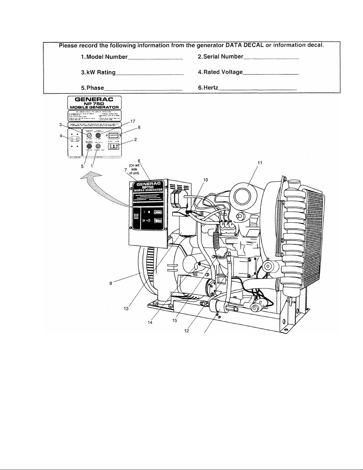
IDENTIFICATION RECORD AND GENERATOR FEATURES
Engine Pre-heat Switch
1.
2. Engine Start/Stop Switch
10 amp DC Circuit Breaker
3.
4. 35 amp AC Circuit Breaker
30 amp Battery Charging Fuse
5.
Generator AC Output Leads
6.
7.
Remote Leads
Hourmeter
8.
Generator
9.
16
REFEREMCE NUMBER IDENTIFICATION
Fuel Return Connection
10.
Air Cleaner
11.
12. Oil Drain Hose
Oil Filter
13.
14. Oil Dipstick
Oil Filler Opening and Cap
15.
Fuel Filter
16.
14 amp Fuse
17.
1 --
Page 4

TABLE OF CONTENTS
OPERATING INSTRUCTIONS
GENERAL SAFETY RULES
IDENTIFICATION RECORD AND
GENERATOR FEATURES.........
READ THIS MANUAL THOROUGHLY
Operation and Maintenance
How to Obtain Service....................................................... 3
Service Dealer Location................................................... 3
GENERATOR FAMILIARIZATION
Generator Applicability....................................................... 4
Installation.......................................................................... 4
Safety................................................................................. 4
Generator AC Connection Systenn
OPERATING INSTRUCTIONS
Generator Control Panel................................................. 5
• Hourmeter
• Engine Start/Stop Switch
• 10-amp Circuit Breaker
• Dual AC Circuit Breaker................................................. 5
• Preheat Switch............................................................. 5
Remote Start/Stop Panel................................................... 5
Before Start-up
Start the Generator............................................................ 6
Shutting Down the Generator
...................................................................... 5
..................................................................
ADDITIONAL INFORMATION
Automatic Low Oil Pressure Shutdown
High Coolant Temperature Shutdown
Overspeed Shutdown
Engine Governed Speed .............................................. 7
25-Hour Break-in Period
25-Hour Check-up Period
Freezing Temperature Operation.................................... 8
Attention Required After Submersion
Operating Precautions..................................................... 8
Effects of Moisture and Dirt............................................... 8
........................................................ 7
....................
inside cover
.............................
..............................................
.................................
...............................................
..................................................
............................................
...
......................
...
.......................
..................................................
...................
...........................
..............................
1
4
7
7
8
7
8
SPECIFICATIONS
Fuel Requirements............................................................. 9
Recommended Fluids
Generator Specifications.................................................... 9
Engine Specifications......................................................... 9
........................................................
9
MAINTENANCE
Periodic Maintenance Schedule....................................... 10
3
5
5
5
6
Overload Protection for Engine DC Elec. System
• 10 amp Circuit Breaker................................................. 10
• 14 amp Fuse............................................................ 10
• 30 amp Fuse................................................................. 10
Checking Fluid Levels....................................................... 11
• Check Engine Oil
• Battery Fluid.................................................................. 11
• Engine Coolant.............................................................. 11
Inspect Generator Set
Inspect Cooling System................................................... 11
Changing Engine Oil........................................................ 11
Coolant Change
Miscellaneous Maintenance............................................. 12
• Cleaning the Generator
• Battery........................................................................ 12
Periodic Replacement Parts
TROUBLESHOOTING
ELECTRICAL DATA
..........................................................
.....................................................
............................................................
..............................................
..........................................
................
............................
............................................
EXPLODED VIEWS AND REPAIR PARTS
WARRANTIES..
.................................................... ..36
............
14
........... 16
10
11
11
12
12
12
13
— 2 —
Page 5

READ THIS MANUAL THOROUGHLY
If you don't understand any portion of this manual,
contact Generac for a demonstration of actual start
ing, operating and servicing procedures.
Throughout this publication and on tags and decals
affixed to the generator, DANGER, WARNING, CAU
TION and NOTE blocks are used to alert you to spe
cial instruction about a particular operation that may
be hazardous if performed incorrectly or carelessly.
Observe them carefully.
These safety warnings cannot eliminate the hazards
that they indicate. Strict compliance with the special
instructions while performing the service plus "com
mon sense" are major measures to prevent acci
dents.
The following definitions apply to DANGER WARN
ING, CAUTION and NOTE blocks found throughout
the manual.
DANGER: indicates an immediately hazardous sit
uation which, if not avoided, will result in death or
serious injury. Danger is limited to the most
extreme situations.
WARNING: Indicates a potentially hazardous situa
tion which, if not avoided, could result in death or
serious injury.
CAUTION: Indicates a potentially hazardous situa
tion which, if not avoided, may result in minor or
moderate injury. Caution may also be used to alert
against unsafe practices.
NOTE; Indicates a statement of company policy as
the message relates directly or indirectly to the safety
of personnel or protection of property.
These symbols indicate the following:
Points out important safety information and, if not
followed, could endanger personal safety and/or
property of yourself and others.
Potential explosion hazard
Potential fire hazard
A
Potential electrical shock hazard
A
The operator (driver) is responsible for proper and
safe use of the vehicle, equipment on the vehicle, and
the safety of all vehicle occupants. We strongly rec
ommend that the operator read this Owner's Manual
and thoroughly understand all instructions before
using this equipment. We also strongly recommend
instructing other occupants in the vehicle to properly
start and operate the generator. This prepares them if
they need to operate the equipment in an emergency.
OPERATION AND MAINTENANCE
It is the operator's responsibility to perform all safety
checks; to make sure that all maintenance for safe
operation is performed promptly; and to have the
equipment checked by an Authorized Dealer periodi
cally. Normal maintenance service and replacement
of parts are the responsibility of the Owner/Operator
and, as such, are not considered defects in materials
or workmanship within the terms of the warranty.
Individual operating habits and usage contribute to
the need for maintenance service.
Proper maintenance and care of your recreational
vehicle generator assures a minimum number of
problems and keeps your operating expenses at a
minimum. See your authorized Dealer/Distributor for
service aids and accessories.
HOW TO OBTAIN SERVICE
When your recreational vehicle generator set requires
servicing or repairs, simply contact an Authorized
Service Facility for assistance. Service technicians
are factory-trained and are capable of handling all of
your service needs.
When contacting an Authorized Service Facility or the
factory about parts and service, always supply the
complete model number and serial number of your
unit as given on its data plate.
The warranty on your generator is included in this
Owner's Manual, as well as listings for repair parts.
SERVICE DEALER LOCATION
TO LOCATE THE NEAREST GENERAC SERVICING DEALER, PLEASE CALL OUR 800 NUMBER.
ONLY DEALER LOCATION INFORMATION CAN BE OBTAINED AT THIS NUMBER.
1-800-333-1322
3 —
Page 6
GENERATOR FAMILIARIZATION
GENERATOR APPLICABILITY
These generators have been designed and manufac
tured for supplying electrical power for recreational
vehicles. You should not modify the generator or use
it for any application other than for what it was
designed. If there are questions pertaining to its
application, write or call the factory. Do not use the
unit until you have been advised by a competent
authority.
DANGER: For fire safety, the generator must have
been properly installed in compliance with (1)
A
ANS1119.2-1975/NFPA 501C-1994 “Standard for
Recreational Vehicles”, Part III, “Installation of
Electrical Systems.” The generator also must have
been installed in strict compliance with the manu
facturer’s detailed installation instructions. After
installation, do nothing that might render the unit
in non-compliance with such codes, standards and
instructions.
You can use this generator to supply electrical power
for operating 120/240 volts, single phase, 60 Hertz,
AC electrical loads requiring up to 7,500 watts (7.5
kW) of power. Those electrical loads cannot exceed
62.5 AC amperes of current at 120 volts, or 31.2 AC
amperes at 240 volts.
CAUTION: Do not overload the generator. Some
installations may require that electrical loads be
alternated to avoid overloading. Applying exces
sively high electrical loads may damage the gener
ator and may shorten its life. Add up the rated
watts of all electrical lighting, appliance, tool and
motor loads the generator will power at one time.
This total should not be greater than the wattage
capacity of the generator. If an electrical device
nameplate gives only volts and amps, multiply
volts times amps to obtain watts (volts x amps =
watts). Some electric motors require more watts of
power (or amps of current) for starting than for
continuous operation.
Owners/Operators have the responsibility to make
sure that nothing is done that might render installation
unsafe or so it will not comply with applicable codes,
standards and instructions.
SAFETY
Before attempting to use the generator set, carefully
read GENERAL SAFETY RULES inside the cover of
this Manual. Comply strictly with these RULES to
prevent accidents and damage to equipment and/or
property. Generac suggests that copying and posting
GENERAL SAFETY RULES in potential hazard areas
of the vehicle. Stress safety to ail operators and
potential operators of this equipment.
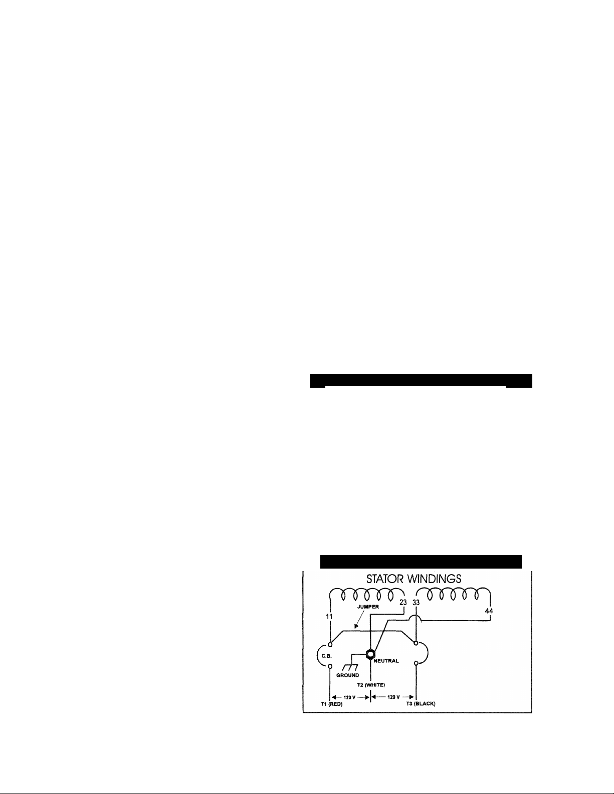
GENERATOR AC CONNECTION SYSTEM
The generator is equipped with a dual stator AC
power windings. These two stator windings supply
electrical power to customer electrical loads by
means of a dual 2-wire connection system. Note,
however, the neutral is grounded.
The generator has been installed so that units power
120/240 volts AC loads (Figure 1); or you can rewire
them to connect only 120 volts AC electrical loads.
Be sure to add jumper wire between circuit breakers
(C.B. in Figure 2) when connecting for 120 volts.
Figure 1 — Connections for 120/240 Volts Only
prmT73 3fwrnp
11
'kTtf
T2 (WHITE)
-----------
120 V
— 240 V —
T1 (RED)
Figure 2 — Connections for 120 Volts Only
120 V
44
T3 (BLACK)
INSTALLATION
This Owner’s Manual has been prepared assuming
that competent, qualified technicians installed the
generators into recreational vehicles. We also
assume installer complied with all applicable codes,
standards and regulations pertaining to installation.
An INSTALLATION MANUAL was shipped with the
generator. That manual contains manufacturer’s
instructions and recommendations for installing the
unit into a recreational vehicle. Following installation,
installers should forward the Installation Manual to
Owner/Operators for their information.
__4__
Page 7
OPERATING INSTRUCTIONS
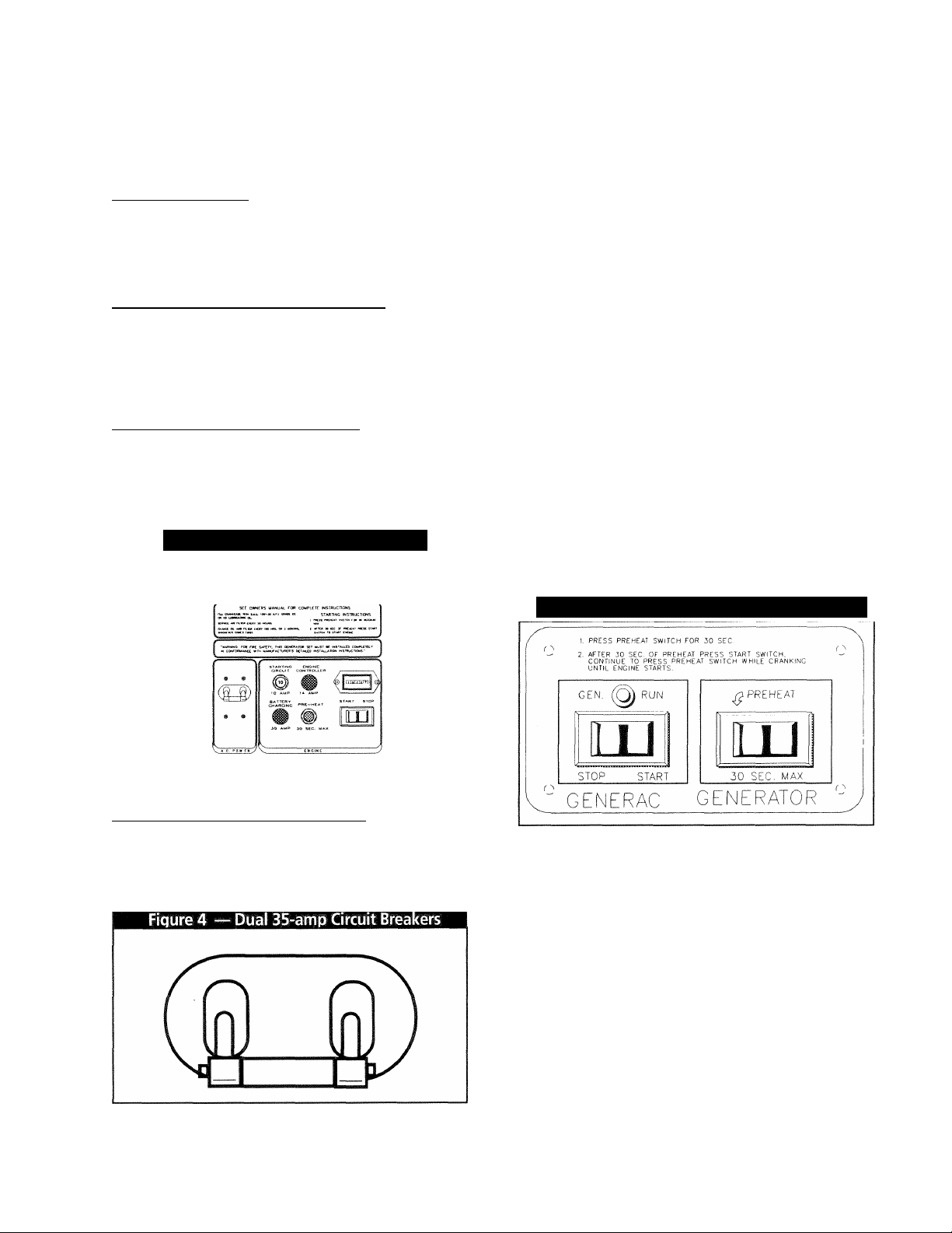
GENERATOR CONTROL PANEL
See Figure 3 to identify the following components;
■ HOURMETER
Provides continuous indication of engine operating
time, in hours and tenths of hours. Use the hourmeter with the periodic maintenance tasks are completed
on a timely basis.
■ ENGINE START/STOP SWITCH
To crank and start the engine, hold switch at its
START position. Release the switch when the engine
starts. To stop an operating engine, press and hold
the switch in its STOP position until the engine shuts
off. The switch center position is the RUN position.
■ 10-AIVIP CIRCUIT BREAKER
Protects the DC control circuit against electrical over
load. If the fuse element has melted open due to over
loading, the engine cannot be cranked, engine preheat
and start functions cannot occur. The breaker is a
“push to reset” type.
Figure 3 — Generator Control Panel
___________
GENERAC
MOBILE GENERATOR
NP75D
___
_________
___________
PREHEAT SWITCH
The diesel engine is equipped with glow plugs, one
for each cylinder. When you press the preheat switch
(Figure 3), the glow plugs heat the engine combustion
chamber for quicker starts in cold weather. To pre
heat the combustion chamber for quicker starts in
cold weather. Press the switch between 15 and 30
seconds. Continue holding in the preheat switch
while cranking the engine until it starts.
NOTE: Refer to THE GENERATOR AC CONNEC
TION SYSTEM on Page 4. Individual installations will
differ. If an overload occurs, the dual breakers will
open the hot stator leads (11 and 44). When the gen
erator has been connected for 120 volts only, one of
the dual circuit breakers will open stator AC output
lead No. 11 (hot lead).
_
A remote mounted Start/Stop Panel (model #9044) is
available, which allows you to start and stop the gen
erator engine conveniently from inside the vehicle
(Figure 5).
You can also order a remote panel (model #9061 )
that includes meters and gauges for monitoring low oil
pressure, high coolant temperature and low coolant
level, in addition to a start/stop switch. The panel
also includes an ammeter, a voltmeter and an
hourmeter.
REMOTE START/STOP PANEL
Figure 5 — Remote Start/Stop & Gauge Panel
M DUAL AC CIRCUIT BREAKER
Rated at 35 AC amps, the circuit breaker (Figure 4) pro
tects the generator’s AC output circuit against overload
and provides a method of turning OFF the generator’s
120/240 volts AC output to vehicle circuits.
___________
— 5 —
BEFORE START-UP
Check Engine Crankcase Oil Level: Refer to
SPECIFICATIONS and MAINTENANCE sections for pro
cedures and recommendations.
CAUTION! Any attempt to crank or start the engine
before properly servicing it with recommended oil
will result in an engine failure.
NOTE: Engine was factory serviced with a high quali
ty oil classified “For Service CD” or “For Service CC”
and having a viscosity rating of SAE 30. The installer
may have refilled the crankcase with an oil more suit
able for ambient temperature ranges in your area.
Page 8

• Check Coolant Level: Check coolant level prior to initial
use and at recommended intervals. Refer to SPECIFI
CATIONS and MAINTENANCE sections for procedures
and recommendations.
• Check Fuel Supply: Make sure an adequate supply of
clean fuel is available to the engine. Many installations
include a Fuel Shutoff Valve, which you must open before
starting the engine.
NOTE: On some installations, the generator may
have been provided with its own fuel tank. On other
installations, the generator may “share” with the vehi
cle’s fuel tank. When the vehicle’s tank is shared,
some installers may have installed a generator fuel
pick up tube in the shared tank that is shorter than the
vehicle’s pick up tube. When a shorter generator fuel
pick up tube is installed in the tank, the generator will
run out of gas while sufficient fuel remains in the tank
for vehicle engine operation.
START THE GENERATOR
To start the generator from either the generator con
trol panel or from the optional Remote Panel, proceed
as follows:
1. Turn OFF electrical loads, using whatever means provided.
NOTE: If starting from the generator panel, turn OFF
loads by setting the generator’s main circuit breaker
to OFF or OPEN. If starting from a Remote Panel,
turn OFF loads using whatever means is provided in
the vehicle (such as a main circuit breaker.)
2. Press the preheat switch (if engine is cold) for between
15 and 30 seconds.
3. At the same time, hold the Engine-Start/Stop Switch at
START and press the preheat switch to crank engine.
Release the switches when the engine starts.
4. Let the engine stabilize and warm up.
5. Turn ON electrical loads, using whatever means provided.
SHUTTING DOWN THE GENERATOR
1. Turn OFF electrical loads, using whatever means
provided.
2. Let the engine run at no-load for a few minutes to
stabilize internal temperatures.
3. Set the Engine-Run/Stop Switch to STOP position.
— 6
Page 9
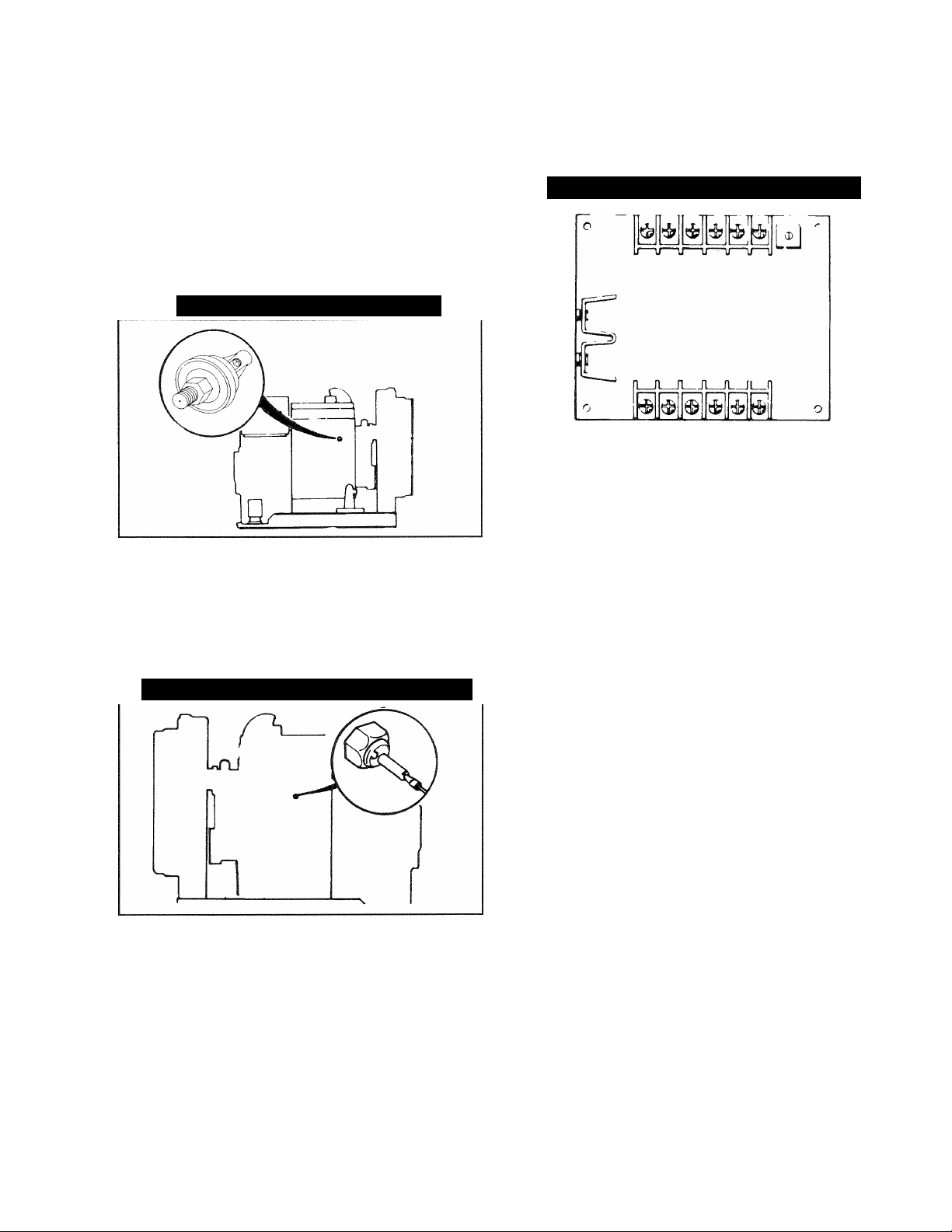
AUTOMATIC LOW OIL PRESSURE
ADDITIONAL INFORMATION
SHUTDOWN
The engine is equipped with a normally-closed (N.C.) oil
pressure switch (Figure 6). Engine oil pressure holds
the switch open during cranking and operation. Should
oil pressure drop below about 10 psi, the switch con
tacts close and the engine automatically shuts down.
Figure 6 — Low Oil Pressure Switch
HIGH COOLANT TEIVIPERATURE SHUTDOWN
This switch (Figure 7) is a normally open (N.O.) ther
mostatic device which is immersed in engine coolant.
Should engine coolant temperature exceed about
250°F (121 °C), the switch contacts close and the
engine shuts down.
Figure 7 — High Coolant Temperature Switch
Figure 8 — Engine Controller Circuit Board
NOTE: After an overspeed shutdown, the engine may
be cranked and re-started. However, if the engine
overspeeds again, the engine will shut down again.
ENGINE GOVERNED SPEED
The generator is equipped with a 4-pole revolving field
(rotor) which must be driven at 1800 rpm to produce
the unit’s rated AC frequency of 60 Hz. The diesel
engine governor was factory set to about 62 Hz. The
diesel engine governor was factory set to about 62 Hz.
(I860) at no-load. After installing it, the installation
technician should check and adjust the governed
speed. Setting the no-load frequency slightly high
helps prevent excessive frequency, rpm and voltage
droop under heavy electrical loading.
OVERSPEED SHUTDOWN
The generator control panel houses an Engine
Controller circuit board (Figure 8). That circuit board
receives AC frequency signals from generator stator
leads 11 and 22. Should AC frequency exceed about
72 Hz (2160 rpm), circuit board action initiates an auto
matic shutdown after a few seconds.
DANGER: Do not tamper with the engine governor
settings. Excessively high engine speeds are dan
gerous and increase the risk of personal injury and
damage to equipment an/or property. Excessively
low speeds impose a heavy load on the engine when
adequate engine power is not available and may
shorten engine life. The generator supplies correct
rated frequency and voltage only at the proper
speed. Some electrical devices may be damaged by
incorrect frequency and/or voltage. If engine speed
appears to be incorrect, contact your nearest autho
rized service facility.
25-HOUR BREAK-IN PERIOD
The first 25 hours of operation is the break-in period for
the generator. Properly breaking in the generator is
essential to reducing oil consumption and enhancing
engine performance. During the break-in period,
observe the following rules:
• For the first 25 hours, run the generator at varying electri
cal loads, to help set the engine piston rings properly.
Page 10

ADDITIONAL INFORMATION
• Following the initial 25-hour break-in period, avoid light
electrical loads for the next 75 hours of operation. The
unit should be loaded at 50% (or more) of its capacity
during those 75 hours. Repeated light loads during
break-in period may improperly seat the piston rings,
resulting in blowby and high oil consumption.
• Check oil level frequently during the break-in period. Add
oil if needed. It is natural for the generator engine to con
sume much oil until the piston rings have seated properly.
• When the 25-hour break-in period is done, complete the
tasks recommended under 25-HOUR CHECK-UP
PERIOD.
25-HOUR CHECK-UP PERIOD
After the first 25 hours of operation have been com
pleted, contact an Authorized Service Facility for the
following maintenance. The Owner/Operator is
responsible for any changes.
Change engine crankcase oil and oil filter.
Check all fluid levels.
Check ail cooling system hoses and fittings for damage,
deterioration, looseness, etc. Check all hose clamps for
tightness and security.
Check engine for proper operation.
Inspect the diesel engine fuel system for leaks, tightness
and security of fuel fittings and hoses.
Inspect V-belts for condition and proper tension.
Inspect the exhaust system for damage, deterioration,
leaks proper operation.
Inspect the electrical system.
Inspect the installation for safety violations, compliance
with codes and standards.
FREEZING TEMPERATURE OPERATION
The engine cooling system should have been proper
ly filled with a 50-50 mixture of low silicate, ethylene
glycol base antifreeze and soft water. When adding
coolant to the radiator or to the coolant recovery bot
tle, add only the recommended 50-50 mixture. Refer
to SPECIFICATIONS section. If the recommended
50-50 mixture is added to the system consistently, the
unit adequately protect against freezing temperatures.
ATTENTION REQUIRED AFTER
SUBMERSION
If the generator has been submerged in water, it must
NOT be started and operated. Following any submer
sion in water, have an authorized Generac Service
Facility thoroughly clean and dry the generator.
OPERATING PRECAUTIONS
Never operate the generator set while the vehicle is
parked over dry leaves, dry grass or any other com
bustible substance. The generator’s exhaust system
becomes extremely hot and can cause fire if it is too
close to combustible materials.
The generator’s exhaust system gives off deadly car
bon monoxide gas. This dangerous gas, if breathed
in sufficient concentrations can cause unconscious
ness and even death. Never operate the generator
set with the vehicle inside any garage or other
enclosed area. Never operate the generator with a
leaking exhaust system. Close windows in the vicinity
of the generator exhaust outlet and take any other
steps that may be necessary to prevent exhaust
gases from entering rooms or areas occupied by peo
ple or animals.
EFFECTS OF MOISTURE AND DIRT
Keep the generator set as clean and dry as possible.
Protect the unit against excessive dust, dirt, corrosive
vapors, road splash, etc. Permitting dirt and moisture
to accumulate on generator windings will have an
adverse affect on the insulation resistance of those
windings.
When moisture is allowed to remain in contact with
windings, some of that moisture will be retained in
voids and cracks in the insulation. This causes a
reduced insulation resistance and will eventually
cause problems. Dirt will make the problem worse,
since dirt tends to hold moisture in contact with the
windings. Sait (as from sea air) will also worsen the
problem since it tends to absorb moisture from the air.
Salt and moisture, when combined, form a good elec
trical conductor.
— 8 —
Page 11

SPECIFICATIONS
FUEL REQUIREMENTS
Recommended fuel is any high quality, automotive
type diesel fuel conforming to JIS No. 2D diesel fuel.
Keep the fuel clean.
RECOMMENDED FLUIDS
Engine Oil: Use a high quality detergent oil classified
“For Service CC or CD” Detergent oils keep the
engine cleaner and reduce carbon deposits. Use oil
having the following SAE viscosity rating, based on
the ambient temperature range anticipated before the
next oil change:
Temperature
above 100°F
40°-100°F
below 40°F SAE 5W-20 or 5W-30
Coolant: Use a mixture of half low silicate, ethylene
glycol base antifreeze and half soft water. Coolant
system capacities may vary, depending on the specif
ic installation, length of system hoses, radiator use,
etc.. Use only soft water and low silicate antifreeze.
If desired, a high quality rust inhibitor may be added
to the recommenced coolant mixture. When adding
coolant, always add the recommended 50-50 mixture.
CAUTION! Do not use any chromate base rust
inhibitor with ethylene glycol base antifreeze or
chromium hydroxide (“green slime”) forms and
causes overheating. You must chemically clean
engines that have operated with a chromate base
inhibitor before adding ethylene glycol base
antifreeze. Using any high silicate antifreeze
boosters or additives will also cause overheating.
In addition, using any soluble oil inhibitor is not
recommended for this equipment.
Oil Grade (recommended)
SAE 40
SAE 10W-30 or SAE 30
GENERATOR SPECIFICATIONS
Model....................................................................NP-75D
Model Number........................................................9344-2
Rated Maximum Continuous
AC Power Output
Rated Voltage
Rated Maximum Continuous
Current
at 120 volts...........................62.5 AC amperes
at 240 volts.............................31.2 AC amperes
Phase
...................................................................1 Phase
Rated AC Frequency
Power Factor................................................................1.0
Number of Rotor Poles....................................................4
Rotor Speed at No-Load
.............................
.......................................
.........................
....................................
7500 watts (7.5 kW)
120/240 volts AC
60 Hz. at 1800 rpm
1860 rpm
ENGINE SPECIFICATIONS
Type of Engine
Cooling Method
Displacement
Combustion Chamber
Cylinders and Arrangement
Bore
............................................
Stroke
..............................................
Compression Ratio
No. of Main Bearings
Break Mean
Effective Pressure .......................
.............................
............................
...............................
...................
..........
.......................
....................
4-cycle diesel
Water-cooled
58.2 inches (954cc)
Swirl Type
3
...2.95 inches (75cc)
2.83 inches (72cc)
23 to 1
5
97
— 9 —
Page 12
MAINTENANCE
PERIODIC MAINTENANCE SCHEDULE
* Performed by Authorized Service Facility
** Performed by Owner/Operator
A. After the first 25 Operating Hours*
1. Change oil and oil filter.
2. Check engine coolant level.
3. Inspect cooling system,
4. Check engine operation.
5. Inspect drive belts.
6. Inspect exhaust system.
7. Inspect electrical system.
8. Inspect battery.
9. Check governed speed setting.
10. Check engine valve clearance.
11. Inspect air cleaner/flame arrestor.
12. Clean the generator.
B. Every 8 Hours of Operation**
1. Check coolant level in coolant recovery bottle.
2. Check fuel level.
3. Check engine oil level.
C. Once Each Week**______________________
1. Inspect the generator set.
2. Inspect the generator battery.
D. Every 100 Hours or Once Each Month**
(whichever comes first)
1. Inspect cooling system.
2. Inspect exhaust system.
E. Every 6 Months or Every 250 Operating Hours*
(whichever comes first)
1. Change engine oil and filter.
2. Check engine operation.
3. Inspect drive belts.
4. Inspect electrical system.
5. Inspect and check battery.
6. Check engine governor setting.
7. Clean or replace fuel filters.
8. Inspect air cleaner/flame arrestor.
9. Clean the generator.
10. Check cooling system and coolant level.
11. Inspect exhaust system.
12. Inspect fuel system.
F. Once Annually or Every 500 Operating Hours*
(whichever comes first)
1. Check engine valve clearance.
2. Check Engine compression and condition.
3. Check fuel injection timing.
4. Check-test fuel injection nozzles.
G. Once Every Two Years*
1. Drain, flush and refill cooling system.
__________
_______
________
_____
____
OVERLOAD PROTECTION FOR
ENGINE DC ELECTRICAL SYSTEM
Engine cranking, start up and running are controlled
by a solid state engine controller circuit board.
Battery voltage is delivered to that circuit board via 10
amp circuit breaker and 14 amp in-line fuse. These
overcurrent protection devices will open if circuit is
overloaded.
CAUTION! If a circuit breaker opens or a
fuse element melts, you should find the
cause of the overload before resetting the
circuit breaker or replacing the fuse.
10 AMP CIRCUIT BREAKER
If the circuit breaker opens due to an overload, you
cannot crank or start the engine. The circuit breaker
is a “push-to-reset” type. For emergency shutdown,
pull the circuit breaker open. Also see “Generator
Control Panel” on Page 5.
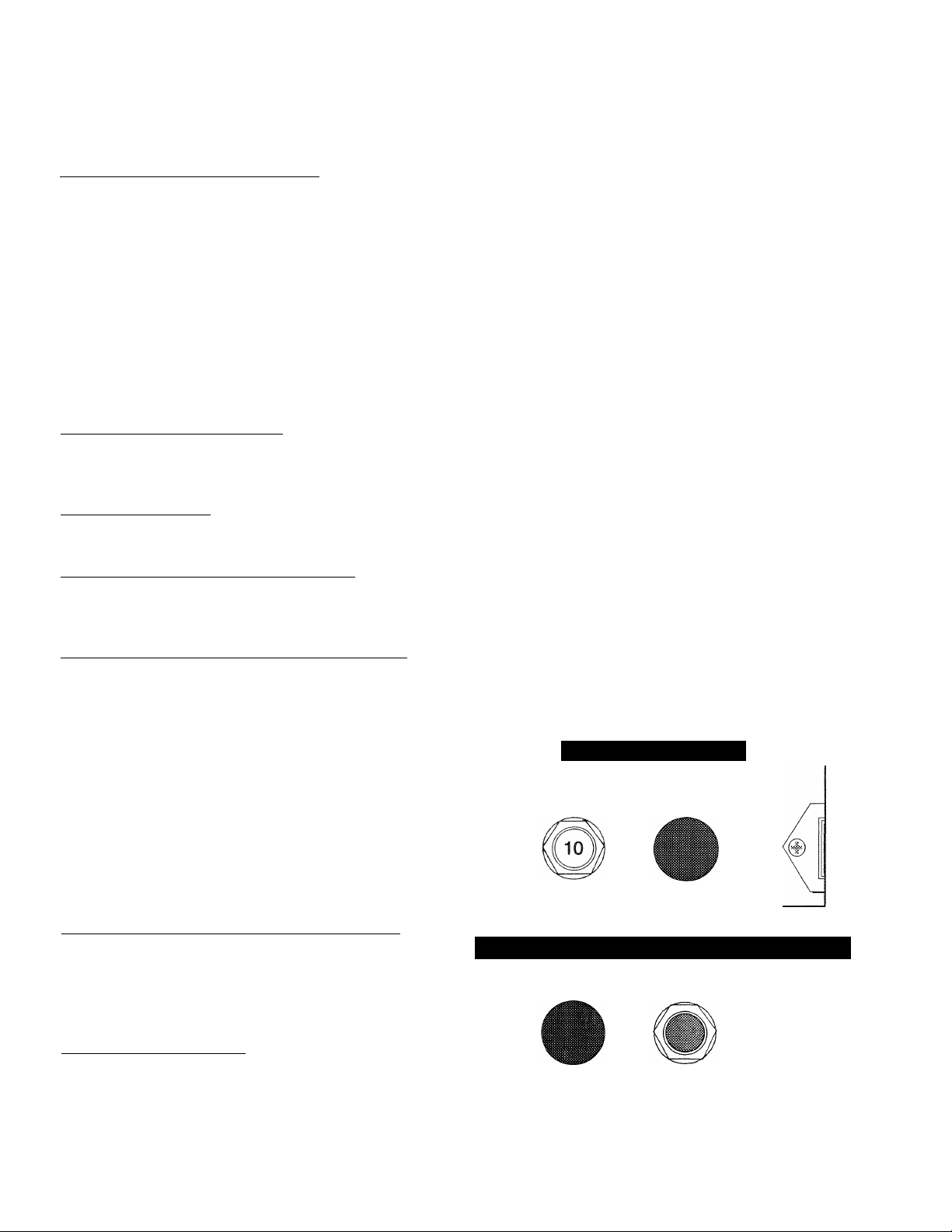
14 AMP FUSE
If the fuse element melts open, you cannot crank or
start the engine. If you must replace the fuse, use
only identical 14 amp fuse (Figure 9).
30 AMP FUSE
The generator set battery is charged during operation
by a DC alternator, driven by the engine. This 30
amp fuse protects the charging circuit against over
load. Should you need to replace the fuse, use only
an identical 30 amp fuse (Figure 10).
Figure 9 — 14 Amp Fuse
STARTING ENGINE
CIRGUIT CONTROLLER
1 O AMP 14 AMP
Figure 10 — 30 Amp Fuse for Battery Charge Circuit
BATTERY
CHARGING PRE—HEAT
30 AMP 30 SEC. MAX
— 10 —
Page 13

CHECKING FLUID LEVELS
■ CHECK ENGINE OIL
Check the engine crankcase oil level at least every 8
hours that you operate the unit, or every time before
you use it (Figure 11).
Figure 11 — Checking Oil Level
• Make sure the generator is as level as possible.
• Remove oil dipstick and wipe dry with a clean, lint
free cloth.
• Install oil dipstick, then remove again.
• Oil should be at dipstick FULL mark. Never operate the
generator with oil level below dipstick ADD mark. DO NOT
FILL CRANKCASE ABOVE DIPSTICK FULL MARK.
■ BATTERY FLUID
Check battery electrolyte fluid at least once weekly. Fluid
should cover separators in ail battery cells. If fluid level is
low, add distilled water to cover tops of separators. DO
NOT USE TAP WATER IN BATTERY.
___________________
INSPECT COOLING SYSTEM
Inspect the entire cooling system once each month or every
100 operating hours, whichever occurs first. Check for
leaks, condition of hoses, and tightness of clamps.
CHANGING ENGINE OIL
Refer to PERIODIC MAINTENANCE SCHEDULE for
engine oil and filter change frequencies. You should also
change generator engine oil before placing the vehicle into
storage.
Drain the oil while engine is still warm from running,
which means warm up the engine, shut it down and
drain immediately as follows (Figure 12):
1. Remove OIL DRAIN HOSE from its retaining clip.
2. Loosen and remove OIL DRAIN HOSE CAP. Drain oil
completely into suitable container.
3. When all oil has drained, install and tighten OIL
DRAIN HOSE CAP.
4. Turn OIL FILTER counterclockwise and remove.
Dispose of old filter.
5. Apply a light coating of new engine oil to seal of new
oil filter. Install FILTER and tighten by hand only. DO
NOT OVERTIGHTEN.
6. Remove OIL FILLER CAP, add recommended oil (see
SPECIFICATIONS). DO NOT OVERFILL ABOVE
THE DIPSTICK TULL” MARK. Crankcase oil
capacity is 3.7 U.S. quarts (3.5 liters).
CAUTION! After refilling the crankcase with oil,
always check oil level on dipstick. NEVER OPER
ATE ENGINE WITH OIL BELOW THE DIPSTICK
“ADD” MARK.
7. Start engine and check for oil leaks.
Figure 12 — Changing Engine Oil
■ ENGINE COOLANT
Check coolant level in coolant recovery bottle.
• Add the recommended coolant mixture as necessary.
• Periodically remove radiator pressure cap to make sure the
coolant recovery system is functioning properly. Coolant should
be at bottom of radiator filler neck. If coolant level is low,
inspect gasket in radiator pressure cap. Replace cap, if neces
sary, To have pressure cap tested, contact an authorized
Generac Service Facility. Inspect cooling system and coolant
recovery system for leaks.
INSPECT GENERATOR SET
Once each week inspect the generator set. Look for fuel,
oil and coolant leaks. Check for missing or loose nuts, bolts
and other fasteners. Check for damage. If unit is dirty, it
may be cleaned with a damp cloth or soft brush. Inspect
the exhaust system. NEVER operate the generator with a
defective exhaust.
11
Page 14

COOLANT CHANGE
Every two years, the cooling system should be
drained, flushed and refilled by an Authorized Service
Facility. See SPECIFICATIONS for cooling system
recommendations.
MISCELLANEOUS MAINTENANCE
■ CLEANING THE GENERATOR
Keep your standby generator as clean and as dry as
possible. Dirt and moisture that is allowed to accu
mulate on internal generator windings have an
adverse effect on insulation resistance.
Periodically clean generator exterior surfaces. A soft
brush may be used to loosen caked on dirt. You can
use a vacuum system or dry, low pressure air to
remove any accumulations of dirt. If the generator is
housed inside an all-weather enclosure, clean the
enclosure with a soft, damp cloth or sponge and
water.
Once each year have the generator cleaned and
inspected by an Authorized Service Facility. That
facility will use dry, low pressure air to clean internal
windings. Parts inside the control console should be
cleaned and inspected date this time as well.
Finally, have the insulation resistance of stator and
rotor windings checked. If insulation resistances are
excessively low, the generator may require drying.
m BAHERY
All lead-acid storage batteries discharge when not in
use. Refer to specific instructions and warnings that
accompany your battery. IF such information is not
available, observe the following precautions when
handling a battery;
____________
DO NOT use jumper cables and a booster battery to
crank or start the generator engine.
DO NOT recharge a weak battery while it is installed in
the generator. Remove battery from generator and
recharge in a well-ventilated area, away from fuel vapors,
sparks, heat or flames.
Battery electrolyte fluid is an extremely caustic sulfuric
solution that can cause severe burns. DO NOT permit
fluid to contact eyes, skin, clothing, painted surfaces,
wiring insulation, etc. If you spill any battery fluid, flush
the affected area with clear water immediately.
Always wear safety glasses, rubber apron and gloves
when handling a battery.
Batteries give off explosive hydrogen gas while charging.
The gas can form an explosive mixture around the bat
tery for several hours after charging. Any spark, heat or
flames can ignite the gas and cause an explosion which
can shatter the battery, causing blindness or other seri
ous injury.
PERIODIC REPLACEMENT PARTS
Part Name Generac Part No.
Oil Filter
Radiator Cap 46627
Air Cleaner Element
Fuel Filter 69858
127-70939
70941
12
Page 15

TROUBLESHOOTING
PROBLEM
Engine won’t crank
Engine cranks but won’t start.
Engine starts hard, runs rough.
POSSIBLE CAUSES REMEDY
1. 10 amp circuit breaker tripped.
2. 14 amp fuse blown.
3. Loose corroded or defective
battery cables.
4. Defective engine Start/Stop switch.
5. Defective starter contactor.
6. Defective starter motor.
7. Low or discharged battery.
1. Vehicle fuel shutoff valve is closed.
2. Out of fuel.
3. Fuel solenoid (FS) is defective.
4. Fuel pump (FP) is defective.
5. Open Wire #14 from Engine Control C.B.
6. Clogged fuel filter or fuel line.
7. Engine mechanical parts failure.
1. Flame arrestor (air cleaner) plugged or
damaged.
2. Defective fuel pump.
3. Plugged fuel filter or fuel line.
4. Water in fuel.
5. Improper pre-heat.
1. Reset circuit breaker.
2. Replace fuse.
3. Tighten clean or replace as
necessary.
4. Replace Start/Stop switch.
5. Replace contactor.
6. Replace starter motor.
7. Charge or replace battery.
1. Open valve.
2. Replenish fuel tank.
3. Replace solenoid.
4. Repair or replace fuel pump.
5. Reconnect wire.
6. Replace if clogged.
7. Repair or replace parts.
1. Clean or replace as needed.
2. Replace or repair fuel pump.
3. Replace filter; unclog fuel line.
4. Drain tank and refill.
5. Pre-heat unit.
Engine starts, shuts down when
Start/Stop switch is released.
Start/Stop Switch at STOP,
engine continues to run.
No AC output from generator.
1. Engine oil level is low.
2. Engine is overheated.
3. Defective low oil pressure switch.
4. Defective coolant temperature switch.
5. Defective engine controller circuit board.
6. Low coolant level.
1. Defective Start/Stop switch.
2. Open/disconnected wire #18 between
Start/Stop switch & engine controller C.B.
3. Open/disconnected wire #0 between
Start/Stop switch & engine controller C.B.
4. Defective Engine Controller circuit board.
1. Check main circuit breaker.
2. Check vehicle circuit breaker & fuses.
3. Generator internal failure.
1. Check oil and add oil as needed.
2. Check cooling system for leaks.
3. Replace switch.
4. Replace switch.
5. Replace circuit board.
6. Repair leak and add antifreeze
mixture as needed.
1. Replace switch.
2. Reconnect/close wire.
3. Reconnect/close wire.
4. Replace board.
1. Reset to ON or CLOSED.
2. Reset and replace, if necessary.
4. Take generator to authorized
Generac service facility.
13 —
Page 16

WIRING DIAGRAM — NP-75D GENERATOR
Drawing No. 83623-A
14
Page 17

_______
ELECTRICAL SCHEMATIC — NP 75D GENERATOR
Drawing No. 83625-
F1 -FUSE 14AMP SFE
F2 -FUSE 30A
FS -FUEL SOLENOID
FP -FUEL PUMP
HM -HOURMETER
HWT-HIGH WATER TEMP SWITCH
LOS-LOW OIL PRESSURE SWTCH
PNC -PREHEAT CONTACTOR
R2 -RESISTOR 10 OHM. 5W
S -STARTER
SC -START CONTACTOR
SW -PREHEAT SWITCH
SW1 -SWITCH. START/STOP
T1 -SENSE TRANSFORMER
TP -THERMAL PROTECTOR
CONNECTION OPTIONS
15
Page 18

EXPLODED VIEW — ENGINE COMMON PARTS
Drawing No. 81982-B
16
Page 19

________
Drawing No. 81982-B
REPAIR PARTS LIST — ENGINE COMMON PARTS
ТЕМ PART NO. QTY.
1 81932 1 ENGINE 1L DIESEL 31
2 35586
3 81946
4
5
6
7 51755 2
8
9
10
11
12
13
14
15
16 81936
17 70941 1
18
19
20
21
22
23
24
25
26
27
28 81939
29
30
81947
55934
22302 4 WASHER, LOCK 36 71956
72501
43107 4 M8-1.25X25MM HHCS
81942 1
49813 6
75674 1 GASKET, EXHAUST
81975
357-70939
42909
42574
60108
26204 1
25507 1
42568
81951
72573
70928
51716
22152
65852 1
71912 1 M5-0.8 X 8MM PPHMS
6
1
1
1
2
1
1 GASKET, MANIFOLD
1 M8-1.25X30MMHHCS 45 56739
1
1 ADAPTOR, 1/8" NPT-1/8"-28 48 40173
1
1
1
1
1
1
5
1
DESCRIPTION ITEM PART NO.
CLAMP, HOSE #20 32
HOSE-RADIATOR, UPPER
HOSE-RADIATOR, LOWER
HOSE CLAMP
M10-1.5X 16MM HHCS 37
SUPPORT, ENGINE
MANIFOLD, EXHAUST
NUT, HEX M6-1.0
OUTLET
OUTLET, EXHAUST-FLEX
CHAMBER, AIR INTAKE 46 75763
FILTER, AIR
SWITCH, OIL PRESSURE
SHAKEPROOF
WASHER M6 50
SHAKEPROOF EXT. 7/16" 51 43146
M8-1.25X20MM HHCS 52
HARNESS, ENGINE WIRE 53
BANJO FITTING ASSY. Ml2
CLAMP, HOSE 55
NUT, HEX-M5-0.8
WASHER, LOCK #10
BRACKET, OIL DRAIN 58
CLIP, OIL DRAIN HOSE 59
QTY.
69811
69860-B 1
33
34
35
38
39 49813
40
41
42
43
44 24114 4
47
49
54 45772 2 NUT, HEXM10x1.5
56
57 71910-A
60
74018
74070
70936
22129
51730
26850
22158
42568
22097
77745
49340
74024 1
45757 1
57642 2 MlOx 1.5 X40MM HHCS
39253 6
72564 1 BRACKET, FUEL FILTER
45771
46233
50190
1
4
4
2
2
12
2
4 NUT, HEX M6-1.0
2
4
4
6
2
2
1
1
1 BARB, 90 DEG. 3/8" x
1
1
4 HEX NUT M8-1.25
1 V-BELT, 3/8"-30-1/8" LONG
1
DESCRIPTION
CAP HEX 1/4" BRASS
HOSE-OIL DRAIN
WASHER, LOCK-MI 2
M12-1.25 X 40MM HHCS
MOUNT, VIBRATOR
WASHER, VIB. ISOLATION
WASHER, LOCK 5/16"-M8
M8-1.25X 60MM
CAPSCREW
SHAKEPROOF EXT 1/4"-M6
NUT, HEX #10-32
M6-1.0X20MM HHCS
WASHER, LOCK 1/4"-M6
NUT, HEX 5/16"-24
SOLENOID, RELAY 12V.
BOOT, RED VINYL
CABLE, STARTER
CLAMP, HOSE #5.5
1/4" NPT
PUMP, FUEL ASSEMBLY
M6-1.0X10MMHHCS
M10-1.0X25MM HHCS
M8x 1.25 x20MM HHCS
LIFTING BRACKET
WASHER, FLAT
SPECIAL-M8
17
Page 20

EXPLODED VIEW — ENGINE BLOCK
Drawing No. 82961
18
Page 21

Drawing No. 82961 -
EXPLODED VIEW — ENGINE BLOCK
ITEM
12
13 144-70939
14
15 146-70939
16 182-70939 1
17
18
19 185-70939
20 186-70939
21
22
23 187-70939
24
25 189-70939
28
29 244-70939 1
30 245-70939 1
31 246-70939
32
33 122-70939 1 GASKET
PART NO. QTY. DESCRIPTION
1
139-70939
2
140-70939 20
143-70939 1
145-70939
183-70939
184-70939
145-70939 2
168-70939
188-70939 1
26073-A 1
145-70939
1
2
1
1 DIPSTICK
1 ROCKER COVER GASKET
1 ROCKER COVER
1 OIL STOPPER
1 SCREEN
1 GASKET
3
1
1 SUCTION FILTER
2
OIL PAN
BOLT
DIPSTICK TUBE
0-RING
BOLT
ROCKER COVER GASKET
BOLT
NUT
CAP
0-RING
1/4” PIPE PLUG SQ.HD
0-RING
TUBING
BOLT
— 19
Page 22

EXPLODED VIEW — CRANKSHAFT, PISTON & FLYWHEEL
Drawing No. 75679-
13
TEi PART NO. QTY. DESCRIPTION
1
2
143-70939
194-70939
3 195-70939
4
196-70939
5 226-70939
6 197-70939
7
200-70939
8 201-70939
9 198-70939 6
10 199-70939 6
11
12
13 208-70939
14
15 210-70939
16 214-70939 3
202-70939 3
203-70939
204-70939
205-70939 3
206-70939
20770939
204-70939
215-70939
216-70939
AR 0.25MM U.S. BEARING 22 221-70939 6
AR
AR
AR 0.50MM U.S. BEARING
AR
AR
CRANKSHAFT ASSEMBLY 17 211-70939 3
1
1 CRANKSHAFT GEAR
1 KEY 212-70939
1 DOWEL PIN
1 SPRING PIN
1
BEARING HOLDER
1 BEARING HOLDER 18
1 BEARING HOLDER 19 218-70939
BOLT 20 219-70939 3
DOWEL PIN
STANDARD BEARING
0.50MM U.S. BEARING 23 222-70939 6
STANDARD BEARING ROD BOLT
0.25MM U.S. BEARING
2 THRUST WASHER
BOLT
2
1 BOLT
STANDARD PISTON
ASSEMBLY
PISTON ASSEMBLY-
0.5MM O.S. AR-AS REQUIRED
PISTON ASSEMBLY-
1.0MM O.S.
ITEM PART NO. QTY. DESCRIPTION
STANDARD PISTON
RING SET
AR PISTON RING SET-
0.5MM O.S.
213-70939
217-70939 3
AR PISTON RING SET-
1.0MM O.S.
PISTON PIN
6 SNAP RING
CONNECTION ROD
ASSEMBLY
21
24
28 230-70939
30 231-70939
U.S.O.S.-
220-70939 3 BUSHING
CONNECTING ROD BOLT
NUT, CONNECTING
223-70939 6
224-70939
225-70939
AR
AR
STANDARD BEARING
BEARING-0.25MM U.S.
BEARING - 0.50MM U.S.
1 PULLEY
1 NUT
- UNDERSIZE
- OVERSIZE
20 —
Page 23

Drawing No. 75678-
EXPLODED VIEW — CYLINDER HEAD
11
1
2
3
4
5
6
7
8 154-70939
147-70939 1
148-70939 6
447-70939 3
149-70939 2
150-70939 3
151-70939 3
152-70939 3
153-70939
3
6
9 155-70939 6
10
11
12
13 160-70939 11
14
15
16
17
18
19
20
21
22
156-70939
157-70939
158-70939 1
159-70939
161-70939
162-70939 2 LIFTING EYE
163-70939
164-70939
165-70939
60108
167-70939
168-70939
169-70939
12
6
3
2
2 BOLT
4 GASKET
CYLINDER HEAD ASSEMBLY
EXPANSION PLUG
EXPANSION PLUG
EXPANSION PLUG
INTAKE VALVE
EXHAUST VALVE
VALVE GUIDE SEAL (EXHAUST)
VALVE GUIDE SEAL (INTAKE)
SPRING
RETAINER
KEY
CAP
CYLINDER HEAD GASKET, 1.2MM THICK
1 CYLINDER HEAD GASKET, 1.3MM THICK
BOLT
BOLT
BOLT
1
1 OIL SWITCH
TUBING
1 THERMO-SWITCH
1
WASHER
21 —
Page 24

EXPLODED VIEW — CAM SHAFT
Drawing No. 75677-
.‘f*—ra,". t*-*
VPk^
.'^'■7'r 'V'
.irr>.
_
ITEM
1
2
3
4
5
6
7
8
9
10
11
12
13
PARING. QTY. DESCRIPTION
232-70939
233-70939
195-70939
234-70939
235-70939
236-70939
237-70939 1 SLIDER
238-70939
239-70939
240-70939
241-70939
242-70939
243-70939
1 CAMSHAFT ASSEMBLY
CAMSHAFT GEAR
1
1 KEY
1 GEAR
SPACER
3
1
BALL BEARING
1 PLATE
1 TACHOMETER SHAFT
1 BOLT
1 BOLT
1
GASKET
1 NUT
22
Page 25

EXPLODED VIEW — CYLINDER BLOCK
TEi PART NO. QTY. DESCRIPTION
1
2
3 101-70939
4
5 103-70939
6
7
8 106-70939
9 107-70939
10 108-70939
11
12
13
14
15
16
100-70939
447-70939
102-70939
104-70939
105-70939
108-70939
110-70939
111-70939
112-70939
113-70939
114-70939 1 BALL BEARING MM = MILLIMETER
115-70939
116-70939
1 COMPLETE CYLINDER
BLOCK
1 EXPANSION PLUG
1 EXPANSION PLUG 20 120-70939
EXPANSION PLUG 21
2
2 EXPANSION PLUG 22 131-70939
1 EXPANSION PLUG
4 PLUG
4
PLUG 25 125-70939
1 IDLE GEAR SHAFT
1
BUSHING
1 BUSHING-STANDARD
1 0.25MM U.S. BUSHING 29
1
0.50MM U.S. BUSHING
1
BALL BEARING
1 EXPANSION PLUG
1
DOWEL PIN U.S. = UNDERSIZE
1
DOWEL PIN
— 23
ITEM PART NO.
17
18
19
23 123-70939
24
26 126-70939
27
28 128-70939 6 PUSH ROD
30 130-70939
117-70939
118-70939
119-70939
121-70939
124-70939
127-70939 6 TAPPET
129-70939
QTY. DESCRIPTION
2
DOWEL PIN
2
SPRING PIN
2 STUD
1 PUSH ROD
1
STUD
1
SNAP RING
1 OIL SEAL
1
DRAIN COCK
1
CONNECTOR
1
OIL FILTER
1
RELIEF VALVE
1
0-RING
Page 26

EXPLODED VIEW — OIL PUMP COMPONENTS
Drawing No. 75682-
ITEM
1
2
3 251-70939
4
5
6
7
8
9
10
11
12
PART NO. QTY. DESCRIPTION
250-70939
252-70939
253-70939
254-70939
255-70939
532-70939
533-70939 AR
258-70939
259-70939
260-70939
261-70939
262-70939
263-70939
264-70939
AR-AS REQUIRED
IDLER GEAR ASSEMBLY
1
1
SPRING
THRUST WASHER
1
1
ROTOR
OIL PUMP COVER
1
AR 0.10MM SHIM
0.15MM SHIM
AR
0.20MM SHIM
0.50MM SHIM
AR
1
SPRING
1 COLLAR
1 SNAP RING
1 FRONT PLATE
1 GASKET
BOLT
3
12
24
Page 27

__________
Drawing No. 75683-
/[fri
EXPLODED VIEW — ROCKER ARM ASSEMBLY
ITEM
1
2
3
4
5
6
7
8
9
10
11
12
iWi
CJ)
-V y. -^i
iV-‘ ^-.7' ■'
PART NO.
170-70939
171-70939
172-70939
174-70939
173-70939
175-70939
176-70939
177-70939
178-70939
179-70939
180-70939 3
181-70939 3
QTY.
DESCRIPTION
1 ROCKER ARM ASSEMBLY
3 INTAKE ROCKER ARM
EXHAUST ROCKER ARM
3
NUT
6
STUD
6
ROCKER ARM BRACKET
3
1 ROCKER ARM SHAFT
2
SPRING
SCREW
2
1
SPRING PIN
NUT
STUD
1 é
25
Page 28

ELECTRICAL DATA
Drawing No.75693-
TO FUEL PUMP
TEM
1
2
3
4
5
6
7
8 74808
9 52233 2 1/8”NPTTEE (BRASS)
10 39450 2
PART NO.
661-70939
69858 1
47290 1 3/8” DIA. HOSE
52221 1 5/16” DIA.HOSE
40173
378-70939
379-70939
QTY.
DESCRIPTION
1 FUEL FILTER SUPPORT
FUEL FILTER
4
NO. 5.5 HOSE CLAMP 14
2 GASKET
1
BANJO FiniNG
1
FUEL BLEED FIHING
1/8” NPTX 3/16”
90-DEGREE
BARBED FiniNG
TO INJUNCTION PUMP
ITEM PART NO.
11
12
13 68736 1
15 74819
16 651-70939
17
18 663-70939 2
30096
68736 1 3/16” DIA. HOSE
74823
662-70939
26 —
QTY.
DESCRIPTION
2
1/8” NPTX 3/16” BARBED
STRAIGHT FITTING
3/16” DIA. HOSE
4
HOSE CLAMP
1
FUEL BLEED FITTING
5 FUEL BLEED GASKET
2
HOLLOW BOLT
BANJO TYPE FITTING
Page 29

Drawing No. 82962-
EXPLODED VIEW — WATER PUMP
ITEM
1
2
3
4
5
6
7
8
9
10
11
12
15
PART NO. QTY. DESCRIPTION
265-70939
266-70939
267-70939
268-70939
269-70939 3
270-70939
271-70939
272-70939
273-70939
274-70939
275-70939
247-70939
284-70939
1 WATER PUMP ASSEMBLY
1
PLUG
1
THERMOSTAT
1
SPRING
GASKET
1 SET PLATE
1
BOLT
1
GASKET
1 BOLT
1
BOLT
1
NUT
1
PULLEY
1
BOLT
— 27
Page 30

EXPLODED VIEW — INJECTOR PUMP
Drawing No. 75686-A
•29
;>Tf-
TEM
1
2
3 298-70939
4
5 32^70939 3
6 323-70939 3
7 324-70939 3
8
9
10
PART NO. QTY. DESCRIPTION
316-70939
317-70939
318-70939
319-70939
320-70939
321-70939
325-70939
326-70939
327-70939
ITEM PART NO. QTY. DESCRIPTION
1
INJECTOR PUMP
ASSEMBLY
AR
AR
AR SHIM-0.5MM 15
AR SHIM-1,0MM
SHIM-0.2MM 13
SHIM-0.3MM
2
NUT
2 BOLT
GASKET
INSERT
CAP 26
3 INJECTOR
1
TUBING 28
1 TUBING
11
12
14
16 332-70939 3 GLOW PLUG
17
18
19
20
27
29
328-70939
329-70939
330-70939
331-70939
298-70939
333-70939
334-70939
335-70939
264-70939
341-90939
342-70939
343-70939
344-70939
P
1
TUBING
1
TUBING
1
CLAMP
1
BOLT
1
NUT
1
CONNECTOR
1 GASKET
1
COVER
2
BOLT
1
SOLENOID
1
WASHER
1
WASHER
1
SCREW
28
AR-AS REQUIRED
Page 31

EXPLODED VIEW — TIMING GEAR HOUSING AND GOVERNOR
Drawing No. 82067-
TEM PART NO. QTY.
1
2
3 287-70939
4
285-70939
28670939 1 SPRING PIN 27 291-70939
307-70939 1
5 308-70939
6 309-70939
7
310-70939 1 STOP LEVER 32 294-70939 1 ARM
DESCRIPTION
1 TIMING GEAR HOUSING
1 GASKET
SPRING 29 292-70939
1 WASHER
NUT
2
8 314-70939 2 COVER
11
12
13 298-70939
14
15 300-70939
16 301-70939
17
18 282-70939
19 288-70939 1 OIL SEAL
20 274-70939 4
21
22
23
24
25
296-70939
297-70939 1
299-70939 1 SHAFT 37
540-70939
311-70939
304-70939 1
305-70939
306-70939 1
289-70939
1 GOVERNOR LEVEL 34
BOLT
NUT
4
1
0-RING 38
1 SNAP RING
BOLT
3
BOLT 41
5
BOLT
BOLT
5
ARM
1 SNAP RING
0-RING 47
1
GOVERNOR LEVEL
ASSEMBLY
ITEM PART NO. QTY. DESCRIPTION
TENSION LEVEL
26 290-70939
28 136-70939
30 313-70939
31 293-70939
33
35
36 271-70939 3 BOLT
39 660-70939
40 534-70939
42
43 537-70939
44
45 188-70939
46 541-70939
295-70939 1
291-70939
302-70939
303-70939
71944
535-70939
536-70939
539-70939
538-70939 3
1
1
SNAP RING
1 WASHER
1
COTTER PIN
1
SPRING
1
SPRING
0-RING
1 SNAP RING
1 BRACKET
2
BOLT
1
HHCS M6-1.0 X 25 MM
1
0-RING
1
0-RING
1
SPACER
1
GASKET
1
HOLDER (OIL FILL)
1
0-RING
1
CAP
1 BOLT
NUT
29 —
Page 32

EXPLODED VIEW — RADIATOR
Drawing No. 83294-B
• INDICATES
tOCATlON or
WEU) STODS
TO W4TS*
nnir
ITEM
1
2 83057
3
4
5
6
7 81977-A
8
9 81946 1
10 82605 1 PLATE, BLOWER HOUSING
11
12
13 66831
14
16
17
18
19
20 52250
21 50832
22
23
24
25 22473 11
26 29451
PART NO. QTY. DESCRIPTION
83098 1
80245
81905 1 FAN, ENGINE
82603 1
83058 1 BRACKET, RADIATOR MOUNTING
81947
22097 7
49813 11
35586 4
42568 11 CAPSCREW, HEX HEAD-M6-1.0 X 20 LONG
56892
58442
46627
5 FT.
81976 1 HUB, FAN
51787
22152
ASSEMBLY, BASE
1
RADIATOR, CROSS FLOW
1
BLOWER HOUSING
RING, FAN INLET
FOAM PAD
2
1
HOSE, LOWER RADIATOR
HOSE, UPPER RADIATOR
LOCK WASHER-1/4"-M6
NUT, HEX-M6-1.0
2 RIVET-POP
HOSE CLAMP #20
6 CRIMPTITE, 10-24X3/8" LONG
2
CRIMPTITE, 1/4"-20X1/2" LONG
1 CAP, RADIATOR
FOAM PAD-3/4"X1" WIDE
1 DRAIN COCK-1/8" NPT
6 CAPSCR., HEX HD.-M4-0.7 X 16 LONG
12
LOCKWASHER-#10
FLATWASHER-1/4"-M6
5' FOAM TAPE-1/8" X 1/2"
30
Page 33

Drawing No. 75685-A
EXPLODED VIEW — DC ALTERNATOR
TEM
1
2
3 72545
4 74007 1
5
6 51753 2
8
9
10
11
12
13
PART NO.
77909
74829
74069
277-70939
345-70939
349-70939
346-70939
348-70939
349-70939
QTY. DESCRIPTION ITEM
1 ADJUSTING PLATE
1 HHCS M8-1.25X30MM
1
LOCK WASHER M8 16
FLAT WASHER Ml0
HHCSM10-1.5X40MM
1
HHCS M6-1.0X40MM
1 ALTERNATOR ASSEMBLY
1 FLYWHEEL
1
BEARING
PLATE ASSEMBLY
1
1
STATOR
1
BEARING
14 352-70939 1
15
17
18 350-70939
19 351-70939 1 NUT
20 137-70939 1 LOCK WASHER
21 280-70939 1
22 356-70939 1
23
24
31
PART NO.
353-70939 1
354-70939 1 SCREW
355-70939 2 SCREW
74827
70005
QTY. DESCRIPTION
COUPLER
CLAMP
1 CAP
WASHER
COLLAR
1
FLAT WASHER M8
2
LOCK WASHER M6-SS
Page 34

EXPLODED VIEW — CONTROL BOX
Drawing No. 83699-B
32
Page 35

Drawing No. 83699-B
TEM
1 23484-F
2
3
4
5 55927
6
7
8
9
10
11 48512 1
12
13 71938-A 1
14
15 83635
16
17
18
19 23762 1
20
21
22
23
24
25 55920 1
PART NO. QTY.
32300 1
81904 1 FUSE HOLDER, 14AMPSFE
22668
75207-B 1 CIRCUIT BREAKER
22220
22155
25433
39271 1
81903
67680 1
74969
36900
22155
81902 1 PANEL, CONTROL
81884-B 1
74076 2 PHM SCREW-M3-0.5 X
77604 1 HOUR METER 48 22188
80825 1
REPAIR PARTS LIST — CONTROL BOX
DESCRIPTION
SNAP-BUSHING SB-1000-12 26 42568
2
FUSE HOLDER, 30 AMP AGO
1 AGO 30 AMP FUSE
1 SFE14AMP FUSE
10 AMP DC
SCREW, ROUND HD. MACH.-
1
#6 X 7/8" LONG
1 LOCK WASHER-#6
GROUND LUG
1
90 DEGREE CONDUIT
CLAMP, 3/4" GREENLEE
CIRCUIT BREAKER, 5AMP
CONTROL BOX 35 51715
1
DC REGULATOR 36
AC REGULATOR ASSEMBLY SCREW
1 AC TRANSFORMER
CIRCUIT BREAKER, 35AMP 39 70325
1
4 PHILLIPS PAN HEAD MACH.
SCREW-#6-32 X 1/4" LONG
4 LOCK WASHER-#6
#10 EXTERNAL LOCK
WASHER
DECAL, CONTROL PANEL 45*
10MM LONG
START/STOP SWITCH 49 22473
PRE-HEAT SWITCH
ITEM PART NO.
27
28
29
30
31*
32
33
34 43184 2 LOCK WASHER-M4
37
40
41
42
44*
46
47
26850
22152
23897
45770 8
77744 1 CUSTOMER LEADS
74041 1
51718 2 M4-0.7X10MM LONG HHCS
80882
72566
22097
51716
55440 2
82617
81951
82737 4
49813
QTY.
10
DESCRIPTION
CAPSCREW, HEX HEAD-M6-
2
1.0X20MM
2 M6EXTERNAL LOCK
WASHER
LOCKWASHER-#10-M5
FLATWASHER-#10-M5
8
CAPSCREW, HEX HEAD-M5-
0.8X10MM LONG
M5-0.8 X 20MM LONG
PHILLIPS PAN HEAD MACH.
SCREW
2 NUT, M4-0.7 HEX
4
#6 X 5/8" SELF TAPPING
4 SPACER NUT
1 ENGINE CONTROLLER
ASSEMBLY
6 LOCKWASHER-1/4"-M6
2
HEX NUT-M5
CAPSCREW, HEX HEAD-M5-
0.8X25MM
1
PANEL WIRE HARNESS
1
ENGINE WIRE HARNESS
VIBRATION DAMPENER
4
NUT-M6-1.0
1
HEX NUT-#6-32
8 FLATWASHER-1/4"-M6
_33
‘NOT SHOWN ON DRAWING
Page 36

EXPLODED VIEW — GENERATOR
Drawing No. C1273-
OJ
34
Page 37

Drawing No. C1273-A
ITEM PART NO. QTY.
1
2
3
4
5
6 81956 1 ASM ROTOR 15” RV 2.5L
7
8 45770
9
10 81974 4
11
12
13
14
15 81192
16 42911
17
18
19 22145
20
21
22 20692 1 MOTOR, STARTER
23
24
25
26 71956
27
28 72553 2
29 45771
30 A-24044-A 4
31 23877-D 2
32 25105 4
33
34
35
36 81991
37
38
39
40 42909 2
41 29107 1
42 25155 1
24488 4 TAPTITE #8 X 5/8"
24911
BN45761
81931
47248
81955
22152
74066 4
22302 4 LOCK WASHER-MI0
81952 1 FLEX PLATE-15” RV15M
81900
81901
82737 4
59450
75763
Cl 271 1 ENGINE ADAPTOR-15”, ISM 1L
39253
70936
22129
82626
BM45761
52858
22097
22127
22237
4 TAPTITE #8 X 3/8”
4
1 REAR BEARING CARRIER 15” RV
1
1
10
6
1 RING FAN
1 FLYWHEEL MACH.-15” ISM
4
1 BAFFLE, AIR RING
4
2
1
4 CAPSCREW, HEX HEAD-M8-1.25 X 20 MM
2 VIBRATION ISOLATOR
2 WASHER, VIBRATION ISOLATOR
8
8
1
4
4
1
1
1
4 LOCKWASHER-3/8
DESCRIPTION
STUD-M8-1.25X 160MM
BALL BEARING-45 MM
ASM STATOR 15” RV2.5L
CAPSCREW, HEX HEAD-M5-0.80 X10MM
LOCK WASHER #10
HHFC/LW M8-1.25X20 MM
HHCS,M10-1,25X30 MM
CAPSCREW, HEX HEAD-MI0-1.50 X 30 MM
MOUNT, VIBRATION
FLATWASHER-5/16-M8
CAPSCREW, SOCKET HEAD-5/16-18 X 1-1/4 LONG
BOOT, BATTERY CABLE
LOCKWASHER-5/16-M8
SCREW, HEX HEAD-M8-1.25 X 60 MM
HEX NUT, M8-1.25
BRUSH ASSEMBLY
HOLDER, BRUSH
PRHMS 6-32X1/4” SIMS
COVER, BRUSH
STUD, M8-1.25X30 MM
NUT FLANGE, HEX-M8-1.25
WIRE ASSEM.-RED
LOCK WASHER-1/4-M6
NUT, HEX-1/4-20
CAPSCR., HEX HD.-M8-1.25 X 30 MM
GROMMET, RUBBER
CLAMP
REPAIR PARTS LIST — GENERATOR
35
Page 38

CALIFORNIA AND FEDERAL EMISSION CONTROL WARRANTY STATEMENT
YOUR WARRANTY RIGHTS AND OBLIGATIONS
The California Air Resources Board (CARS) and the United States Environmental Protection Agency (EPA), together
with Generac Power Systems, Inc. (Generac), are pleased to explain the Emission Control System Warranty on your
new engine.* New utility, and lawn and garden equipment engines must be designed, built and equipped to meet
stringent anti-smog standards for the state of California and the federal government. Generac will warrant the
emission control system on your engine for the periods of time listed below provided there has been no abuse,
neglect, unapproved modification or improper maintenance of your engine.
Your emission control system may include parts such as the carburetor, ignition and exhaust systems. Generac will repair
your engine at no cost to you for diagnosis, replacement parts and labor, should a warrantable condition occur.
MANUFACTURER’S EMISSION CONTROL SYSTEM WARRANTY COVERAGE:
Emissions control systems on 1997 and later model year engines are warranted for two years as hereinafter noted. If,
during such warranty period, any emission-related component or system on your engine is found to be defective in
materials or workmanship, repairs or replacement will be performed by a Generac Authorized Warranty Service Facility.
PURCHASER’S/OWNER’S WARRANTY RESPONSIBILITIES:
As the engine purchaser/owner, you are responsible for the completion of all required maintenance as listed in your
factory supplied Owner's Manual. For warranty purposes, Generac recommends that you retain all receipts covering
maintenance on your engine. However, Generac cannot deny warranty solely because of the lack of receipts or for
your failure to ensure the completion of all scheduled maintenance.
As the engine purchaser/owner, you should, however, be aware that Generac may deny any and/or all warranty cov
erage or responsibility if your engine, or a part/component thereof, has failed due to abuse, neglect, improper
maintenance or unapproved modifications, or the use of counterfeit and/or 'grey market' parts not made, supplied
or approved by Generac.
You are responsible for presenting your engine to a Generac Authorized Warranty Service Facility as soon as a prob
lem occurs. The warranty repairs should be completed in a reasonable amount of time, not to exceed 30 days.
Warranty service can be arranged by contacting either Generac or a Generac Authorized Warranty Service Facility at
the following address:
GENERAC POWER SYSTEMS, INC. PH; (414) 544-4811
P.O. BOX 8 FAX; (414) 544-0179
WAUKESHA, Wl 53187
IMPORTANT NOTE: This warranty statement explains your rights and obligations under the Emission Control System
Warranty (ECS Warranty), which is provided to you by Generac pursuant to California and federal law. See also the
"Generac Limited Warranties for Generac Power Systems, Inc.," which is enclosed herewith on a separate sheet, also
provided to you by Generac. The ECS Warranty applies only to the emission control system of your new engine. If there
is any conflict in terms between the ECS Warranty and the Generac Warranty, the ECS Warranty shall apply except in cir
cumstances where the Generac Warranty may provide a longer warranty period. Both the ECS Warranty and the
Generac Warranty describe important rights and obligations with respect to your new engine.
Warranty service can be performed only by a Generac Authorized Warranty Service Facility. When requesting warranty
service, evidence must be presented showing the date of the sale to the original purchaser/owner. The purchaser/owner
shall be responsible for any expenses or other charges incurred for service calls and/or transportation of the product
to/from the inspection or repair facilities. The purchaser/owner also shall be responsible for any and/or all damages or
losses incurred while the engine is being transported/shipped for inspection or warranty repairs.
If you have any questions regarding your warranty rights and responsibilities, you should contact
Generac at (414) 544-4811.
Part 1
36 —
Page 39

EMISSION CONTROL SYSTEM WARRANTY
Emission Control System Warranty (ECS Warranty) for 1997 and later model year engines:
(a) Applicability; This warranty shall apply to 1997 and later model year engines. The ECS Warranty Period shall begin
on the date the new engine or equipment is purchased by/delivered to its original, end-use purchaser/owner and
shall continue for 24 consecutive months thereafter.
(b) General Emissions Warranty Coverage: Generac warrants to the original, end-use purchaser/owner of the new
engine or equipment, and to each subsequent purchaser/owner, that each of its engines is...
(1) Designed, built and equipped so as to conform with all applicable regulations adopted by the EPA and CARS
pursuant to their respective authority, and
(2) Free from defects in materials and workmanship which, at any time during the ECS Warranty Period, may cause
a warranted emissions-related part to fail to be identical in all material respects to the part as described in the
engine manufacturer's application for certification.
(c) The ECS Warranty only pertains to emissions-related parts on your engine, as follows:
(1) Any warranted, emissions-related parts that are not scheduled for replacement as required maintenance in the
Owner's Manual shall be warranted for the ECS Warranty Period. If any such part fails during the ECS Warranty
Period, it shall be repaired or replaced by Generac according to Subsection (4) below. Any such part repaired or
replaced under the ECS Warranty shall be warranted for the remainder of the ECS Warranty Period.
(2) Any warranted, emissions-related part that is scheduled only for regular inspection as specified in the Owner's
Manual shall be warranted for the ECS Warranty Period. A statement in such written instructions to the effect of
"repair or replace as necessary" shall not reduce the ECS Warranty Period. Any such part repaired or replaced
under the ECS Warranty shall be warranted for the remainder of the ECS Warranty Period.
(3) Any warranted, emissions-related part that is scheduled for replacement as required maintenance in the
Owner's Manual shall be warranted for the period of time prior to the first scheduled replacement point for that
part. If the part fails prior to the first scheduled replacement, the part shall be repaired or replaced by Generac
according to Subsection (4) below. Any such emissions-related part repaired or replaced under the ECS Warranty
shall be warranted for the remainder of the ECS Warranty Period prior to the first scheduled replacement point
for such emissions-related part.
(4) Repair or replacement of any warranted, emissions-related part under this ECS Warranty shall be performed at
no charge to the owner at a Generac Authorized Warranty Service Facility.
(5) When the engine is inspected by a Generac Authorized Warranty Service Facility, the owner shall not be held
responsible for diagnostic costs if the repair is deemed warrantable.
(6) Generac shall be liable for damages to other original engine components or approved modifications proximate-
ly caused by a failure under warranty of any emission-related part covered by the ECS Warranty.
(7) Throughout the ECS Warranty Period, Generac shall maintain a supply of warranted emission-related parts suf
ficient to meet the expected demand for such emission-related parts.
(8) Any Generac authorized and approved emission-related replacement part may be used in the performance of
any ECS Warranty maintenance or repairs and will be provided without charge to the purchaser/owner. Such use
shall not reduce Generac's ECS Warranty obligations.
(9) Unapproved, add-on, modified, counterfeit and/or 'grey market' parts may not be used to modify or repair a
Generac engine. Such use voids this ECS Warranty and shall be sufficient grounds for disallowing an ECS
Warranty claim. Generac shall not be held liable hereunder for failures of any warranted parts of a Generac
engine caused by the use of such an unapproved, add-on, modified, counterfeit and/or 'grey market' part.
EMISSION RELATED PARTS INCLUDE THE FOLLOWING:
1) Fuel Metering System:
1.1) Gasoline carburetor assembly and its
internal components (if so equipped).
a) Fuel filter (if so equipped)
b) Carburetor gaskets
c) Fuel pump (if so equipped)
1.2) LPG carburetion assembly and its
internal components (if so equipped).
a) Fuel controller (if so equipped)
b) Mixer and its gaskets (if so equipped)
c) Carburetor and its gaskets (if so equipped)
d) Primary gas regulator (if so equipped)
e) LP liquid vaporizer (if so equipped)
*Generac engine types covered by this warranty statement include the following;
1) Utility
2) Lawn and Garden Equipment
3) Recreational Vehicle (RV) Generator
4) Industrial Mobile (IM) Generator
Part 2
2) Air Induction System including:
a) intake pipe/manifoid
b) Air cleaner
3) Ignition System including;
a) Spark plug
b) Ignition module
4) Catalytic Muffler Assembly (if so equipped) including;
a) Muffler gasket
b) Exhaust manifold
5) Crankcase Breather Assembly including:
a) Breather connection tube
37
*
Page 40

Generac’s Three-Year Limited Warranty For Recreational Vehicle Generators
Generac warrants to the original owner and subsequent purchasers from the date of purchase by the original owner, that its generators
will be free from defects in materials or workmanship for the period as set forth below. During said warranty period, Generac will, at its
option, repair or replace any part which, upon examination by Generac or a Generac Authorized Distributor and/or Dealer thereof, is
found to be defective from normal use and service.
This warranty is only effective, upon Generac’s receipt from the original owner, a completed Warranty Registration Card, prior to the expi
ration of the warranty period. This card is the only valid registration identification and must be presented at time of requesting Warranty
service. Claims will not be accepted without presentation of this Registration Card.
THREE YEAR WARRANTY SCHEDULE
1. Ail generators used in a recreational vehicles shall be warranted for a period of three (3) years or 2,000 hours of operation, whichev
er occurs first. All parts, labor, removal and reinstallation shall be covered for the first two years. Parts and labor on selected gener
ator and engine parts shall be covered during the third year or 2,000 hours, whichever occurs first. These selected parts are limited
to: the main Rotor and Stator, Computer Control board (if applicable) with regard to the generator; the Cylinder Block, Cylinder Head,
Crankshaft, Piston, Valve, Valve Lifter, and Manifolds with regard to the engine.
2. The drive belt and pulleys (if so equipped) on air-cooled generator used in recreational vehicles shall be warranted against failure
due to defective materials or normal usage for the life of the generator. For the original owner, this drive belt and pulley warranty
shall include parts and labor plus $50.00 payment upon return of the failed belt or pulley by the original owner. For succeeding
owners, this drive belt warranty shall cover belt or pulley parts only.
3. Rental units, demonstrators, prime power, or commercial applications, such as construction or utility, are warranted for (1) one year
or 2,000 hours, whichever comes first.
4. This transferable warranty is in effect for all Recreational Vehicle Generators purchased after Jan. 1,1998.
THIS WARRANTY DOES NOT COVER:
• Costs of maintenance, installation, and start-up.
• Failures due to (a) normal wear and tear from GN engine, or (b) accident, misuse, abuse, negligence or improper installation.
• Products which are modified or altered in a manner not authorized by Generac in writing.
• Any incidental, consequential or indirect damages caused by defects in materials or workmanship, or any delay in repair or
replacement of defective parts.
• Failure due to misapplication.
• Telephone, telegraph, teletype or other communication expense.
• Living or travel expenses of persons performing service.
• Any and all transportation/travel expenses.
• Rental equipment used while warranty repairs are being performed.
• Overtime labor.
• Starting batteries, fuses, light bulbs, and engine fluids.
**NORMAL WEAR: As with all mechanical devices, the GN-Series engines need periodic parts service and replacement to per
form well. This warranty will not cover repair when normal use has exhausted the life of a part or an engine.
There is no other express warranty. Generac hereby disclaims any and all implied warranties, including but not limited to those of mer
chantability and fitness for a particular purpose to the extent permitted by law. The duration of any implied warranties which cannot be
disclaimed is limited to the time period (one year) as specified in the express warranty. Liability for consequential, incidental or special
damages under any and all warranties is excluded to the extent permitted by law. Some states do not allow limitations on how long an
implied warranty lasts, or the exclusion or limitation of incidental or consequential damages, so the above limitations or exclusions may
not apply to you. This warranty gives you specific legal rights and you may also have other rights, which vary from state to state.
For service, see your nearest GENERAC authorized warranty service facility or call 1-800-526-2871. Warranty service can be performed
only by a GENERAC authorized service facility. This warranty will not apply to service at any other facility. At the time of requesting war
ranty service, evidence of original purchase date must be presented.
Generac Power Systems, Inc.
P.O. Box 8 • Waukesha, Wl 53187
Telephone: (414) 473-5514 Fax: (414) 472-6505
 Loading...