

Page 1

0^
fY^
Part No. 83874
OWNER’S
Manual
SERIES NP-80D
LIQUiD-COOLED
RECREATIONAL VEHICLE
GENERATOR
Model 9344-1
Revision 0(8/18/92)
CORPORATION
Printed in U.S.A.
Page 2

GENERAL SAFETY RULES
THE MANUFACTURER SUGGESTS THAT THESE "RULES" FOR SAFE OPERATION BE COPIED AND
POSTED IN POTENTIAL HAZARD AREAS OF THE RECREATIONAL VEHICLE. SAFETY SHOULD BE
STRESSED TO ALL OPERATORS AND POTENTIAL OPERATORS OF THIS EQUIPMENT.
Study these SAFETY RULES carefully before operating
or servicing applicable equipment. Become familiar
with this Owner’s Manual and with your generator.
Safe, efficient and reliable operation can only be
achieved if generator is properly installed, operated and
maintained. Many accidents are caused by failing to
follow simple and fundamental rules or precautions.
The manufacturer suggests that these GENERAL
SAFETY RULES be copied and posted in potential
hazard areas of the recreational vehicle. Stress safety
to all operators and potential operators of this equip
ment.
The manufacturer cannot possibly anticipate every pos
sible circumstance that might involve a hazard. The
warnings in this manual, therefore, are not all-inclusive.
If you use a procedure, work method or operating tech
nique that Generac does not specifically recommend,
you must satisfy yourself that it is safe for you and
others. You must also make sure the procedure, work
method or operating technique that you chose, does not
render the generator to be unsafe.
• For fire safety, the recreational vehicle generator
must be properly installed and maintained. Instal
lation must comply with applicable codes and stan
dards. Also, the generator must be installed to
conform to the manufacturer’s detailed installation
instructions. After installation, do nothing that might
render the generator in noncompliance with such
codes, standards and instructions.
• The recreational vehicle generator produces ex
tremely dangerous electrical voltages and can
cause dangerous, and possibly fatal, electrical
shock. Avoid contact with bare wires, terminals,
etc., while the unit is running. If you must work
around an operating generator, stand on an insu
lated, dry surface to reduce shock hazard.
• Never work on this equipment or handle any elec
trical device while standing in water, while barefoot,
or while hands or feet are wet. Dangerous electrical
shock will result.
• Have the generator properly grounded (bonded)
during installation onto the vehicle, either by solid
mounting to the vehicle frame or chassis or by
means of an approved bonding conductor, if so
equipped. DO NOT reconnect the bonding conduc
tor to any generator part that might be removed or
disassembled during routine maintenance. If the
grounding conductor must be replaced, use only a
flexible conductor that is of No. 8 AWG copper wire
minimum.
Inspect fuel system frequently for leaks or damage.
Repair or replace any damaged or leaking compo
nent immediately. Never attempt to change, alter
or modify the generator fuel system in any way that
might affect safety or compliance with applicable
codes and standards.
In case of accident caused by electric shock, shut
down the source of electrical power at once. If you
cannot do this, free the victim from live conductor.
AVOID DIRECT CONTACT WITH THE VICTIM.
Use a dry board, dry rope, or other non-conducting
tool to free the victim from live conductor. If victim
is unconscious, apply CPR (cardio-puimonary re
suscitation) and get medical help.
The generator engine gives off DEADLY carbon
monoxide gas through its exhaust system. This
dangerous gas, if breathed in sufficient concentra
tions, can cause unconsciousness or even death.
This exhaust system must have been properly in
stalled, complying strictly with applicable codes and
standards. After installing the unit, do nothing that
might render the unit unsafe or in non-compliance
with such codes and standards. The generator
compartment must be completely vapor-seaied
from vehicle interior. There must be no possibility
of exhaust fumes entering the vehicle interior.
Never operate this equipment with a leaking or
defective exhaust system.
Never use the generator or any of its parts as a step.
Stepping on the unit can stress and break parts and
may result in dangerous operating conditions from
leaking exhaust gases, leaking fuel, leaking oil or
leaking coolant.
The generator compartment needs adequate venti
lation to expel toxic fumes and diesel fuel vapors.
Do not alter the installation in any way that might
obstruct air and ventilation openings. Keep such
openings clear and unobstructed.
Keep hands, feet, clothing away from drive belts,
fans and other moving parts of this equipment.
Never remove a drive belt or fan guards while the
unit is operating.
Although diesel fuel is not as volatile as gasoline or
LP gas (liquid propane), it is still dangerous. Com
ply strictly with all laws and regulations regarding
the handling of diesel fuel.
Inspect the generator periodically. Repair or re
place all damaged or defective parts immediately.
Before performing any maintenance on the gener
ator set, disconnect its battery cables to prevent
accidental starting. First disconnect the cable from
the battery post indicated by a NEGATIVE, NEG or
(-)• Reconnect that cable last.
Page 3

IDENTIFICATION RECORD
Please record the following information. Find this information on the Model/Seria! Number Plate and on the
Generator Data Plate, affixed to your generator.
Model Number
Rated kW
Rated Hertz
Serial Number
Rated Volts
Rated RPM
1 -
Page 4

READ THIS MANUAL THOROUGHLY
If you don’t understand any portion of this manual,
contact Generac for a demonstration of actual starting,
operating and servicing procedures.
Throughout this publication and on tags and decals
affixed to the generator, DANGER and CAUTION
blocks are used to alert you to special instructions about
a particular operation that may be hazardous if per
formed incorrectly or carelessly. Observe them care
fully.
These safety warnings cannot eliminate the hazards
they indicate. Complying strictly with the special in
structions while servicing the unit plus "common sense"
are major measures for preventing accidents.
The following definitions apply to DANGER, CAUTION
and NOTE blocks found throughout the manual.
DANGER! AFTER THIS HEADING YOU CAN
READ INSTRUCTIONS FOR HANDLING, IN
STALLING OR SERVICING THAT, IF NOT COM
PLIED WITH STRICTLY, MAY RESULT IN PER
SONAL INJURY.
the generator. This prepares them if they need to oper
ate the equipment in an emergency.
OPERATION AND MAINTENANCE
The operator is responsible for performing all safety
checks: to be sure that all maintenance for safe opera
tions is performed promptly; and to have the equipment
checked by an Authorized Dealer periodically. Normal
maintenance service and replacement of parts are the
responsibility of the Owner/Operator and, as such, are
not considered defects in materials or workmanship
within the terms of the warranty. Individual operating '
habits and usage contribute to the need for maintenance
service.
Proper maintenance and care of your recreational vehi
cle generator keeps the number of problems to a
minmum and keeps your operating expenses low. See
your authorized Dealer/Distributor for service aids and
accessories.
CAUTION! After this heading you can read instruc
tions for handling, installing or servicing that, if not
complied with strictly, may result in damage to
equipment and/or property.
NOTE: After this heading you can read explanatory
statements that require special emphasis.
The operator (driver) is responsible for proper and safe
use of the vehicle, equipment of the vehicle and the
safety of all vehicle occupants. We strongly recom
mend that the operator read this Owner’s Manual and
thoroughly understand ail instructions before using this
equipment. We strongly recommend instructing other
occupants in the vehicle to properly start and operate
HOW TO OBTAIN SERVICE
When your recreational vehicle generator set requires
servicing or repairs, simply contact an authorized Ser
vice Station for assistance. Service technicians are
factory-trained and are capable of handling all of your
service needs.
When contacting an Authorized Service Facility of the
factory about parts and service, always supply the com
plete model number and serial number of your unit as
given on its data plate.
The warranty of your generator is included in this
Owner’s Manual as are listing for repair parts.
-2-
Page 5

GENERATOR FEATURES
1. Engine Pre-heat Switch
2. Engine Start/Stop Switch
3. 10 amp DC Circuit Breaker
4. 35 amp AC Circuit Breaker
5. 30 amp Battery Chargingn Fuse
6. Generator AC Output Leads
7. Remote Leads
8. Hourmeter
9. Generator
10. Fuel Return Connection
11. Air Cleaner
12. Oil Drain Hose
13. Oii Filter
14. Oil Dipstick
15. Oil Filler Opening and Cap
16. Fuel Filter
17. 14 amp Fuse
-i-
Page 6

G F r-J E n AT 1 ■ R_ Mì „ ? A R i/
GENti^.Al Jrt APPLÍCAbi'_r,'¡
These gr^nerators have been designer and rranuiac
tured ior he purpose of suppi'/ing elcetn^ai f^ower for
recreational vehicle You chouLi not modify * *ne gen
erator or L sp n f:' ally appiif atiuh oin- tfian fa wha' is
was detiyiibC. 1 ^sie-e are inv ouesi- n.- pe"*-inii o to
its application wri.>- or ''iH Tie r iciogc Do -a esc tne
unit until cl comnpifcni a'of'of'D r.ar “jv.sf*nv<t
DANGEn FOF FiRE 3ÄFE1 . i HL
MUST HAVE SEEK' FROPERLf iNSlALLED IK
COMPLIANCE W\lh AFPLrOAPLE TCCES AND |
ST ^NDARD" TEE GENERATOR ALSO MOST
hA/E SEEN iNSfAuLED IN STRiCT GOMPLin
ANCE mdTh THE MANÖFACTPi^Efl S DFTAIlSO i
INSTALLATION iWSTF.OCTlC NS FOLLGWiNG IN- j
STAuI^fiTIOM. NOTHiYG MUST EE DONE ThA^ |
M^GKT RENDER TNE JHll IN NON-OOMFLiANCe |
WiTh AuCh OD^ .S**ANr'^FOS A!4D Os-i
STRIjCJjf^liS.
______
_____ ______
_______
_ J
Yolljii c ihi£ ue ' r:ur-titucupDyw'
fof s'Prraliiiy iOjE-^'j ^ ills Jncle chase r '
ek Cl If '*'f ,ii< juifirg id'o ‘''C0v*,i:e/ - fVd !
pr)we Y -• T aac .anr-a • >i com: "
a - uDr “f . fit r i IPO‘'Of' i"“, . ^ '"OCf fc
cl oo V' k'
The owner/operaior should be sure the unit has been
installed to allow adequate ventillation for cooling and
exhaust air.
SAFETY
Before attempting to use the generator set, carefully
read GENERAL SAFETY RULES inside the cover of
this Manual. Comply stricly with these RULES to pre
vent accidents and damage to aauipment and/or prope’~y. r-ne-r-c Ciijaesio that copy. g and posting GEN
ERAL S-FFT RL re n peteriO* hazard areas of the.
vapirie 'ire:, sarnty ^ ^ ope ators and potential
'perah • 1 fOO 'Vi.'nfrji
GENErATSiP A^C CONNECTION SYSTEM
"h' per b pjr (: ^ win a -mal stator AC power
vcs.dingc rn- i- ' c . UvV wind res supply electrical
• G ce" T curtemH-r u' ci' jc 'oacm by means of a dual
d '/r I' ,i-mh{yfi /"if M Uc-e, .loweverOhe neutral
c QiijMm-h
■“ht mtm h . '-ij'k*, s > that units power
r/j/'* -0 -Of . ‘,,a! y aiurf i): c r you can rewire
'hs n ffu(Iir~ on / lO'v !’c k( !f ctrical loads. Be
jff r Un ^ nrki"f n ci'mjif breakers (C.B.
ji ~ lum . ) Alb ' -.1 I. -U> tj io' L 'olts
i ounON. Oc TUI ove"ioacJ the q t n t tn h i ^ero^IriStakaA&rT!-.'j row|uite inai n eoc
die r'’uceo'o 0'a-itiii ov*-f|:cd'ng feoriciCic »'
• v'^i ' Of h ' .f 1. |, 1 ,-f
I '» c^fien f .!>' ' s<n "rh
•n. ’ ( .al '“ir III mi * -I-. *i mi s c ^ ‘ '
T ' i' m^- r fi- ,'0'j‘ "*** , I"» if"t 1 Of » 3<.»
“h
r- 5 im C» - »1 -jouc . Oí '
«' '-rk m- n Í ' il/ ^
I! ‘ - . p, C'Ok- Hi (.íuíí, ,f .Í ’ f
should not be areale
-, i Or t ’ / ,
if ;i,< !. i< L
i V
Ou >i2 iuun t n-c/ egufro si’t.o /«.m f
p.wef iOr Ä.i pa m. ' ut cml mn 'm * m.,* Ii ' :cm
Í viiursouua - tt
IhOTALL.O.OOrv
Ì hi T/ -I ' fdac -I " c i-t it -cr. fr!''''iio 'jinm
'Ui.ffm-p iimh-a u if t;r ni '“.ri. ./„!! j
mr- iPtc r-_cr-:5aur,, ,0 v'/v dice csct r^r-
.C'npiic J ,vkh O'COaDle C'^nec c'ar ,a'' L a d ~
u'Ci ' '-'C Dtrre'ntny ÍC- n'iaiia''i.jn
An k4‘'TMLi_AT‘Aju HANUA* wm- <ri!pD“ö *"c
^mcf-rarnr T*ri¿.| Mnuii emmne nertmOn'" c •“
orjcffcr"- and reLorT.mpnriai'crn c¡ I'^oaJina ..*m rt
rtic a r-creOicnni cehi'ie rollovxsnq .nomiia:r-r ,r
cjii„ a sneuid 'erma'-d tne incmliaron Oa .uri
Awner/Operaiors Or ihsi. .normakoo r-r-Cc''!'
- !• rCSO'^o. ÌO
JCP' Oidi m.ght Ibi.de^'--mon'r msem rcy; /^¡¡i im
m\ V iih -upOcLie c ano'* ca -^tn if-on¡ -
j 1/ 0 0 i) <) ' G
T2 (WHITE)
-120 V,
-240 vC
T1 (RED)
Figure 1 — Connections for 120/240 Volts
Figure 2 — Connections for 120 Volts Only
44
öCn
cm
J
T3 (BLACK)
4 -
Page 7

OPERATION
GENERATOR CONTROL PANEL
See Figure 3 to identify the following components:
Hourmeter: Provides continous indication of engine
operating time, in hours and tenths of hours. Use the
hourmeter with the periodic maintenance schedule, to
make sure that required periodic maintenance tasks are
completed on a timely basis.
Engine-Stop/Start Switch: To crank the engine, hold
switch at START position. Release the switch when the
engine starts. To shut down an operating engine, set
the switch to STOP.
10-Amp Circuit Breaker: Protects the DC control cir
cuit against overload. If the circuit breaker has opened
due to an overload, engine preheat and start functions
cannot occur. The breaker is a "push to reset" type.
G E N E R A C
N P 8 0 D
R V GENERATOR
•MAr.'.iAL fOP COMh
E CC 0« ^ '
Preheat Switch: The diesel engine is equipped with
glow plugs, one for each cylinder. When you press the
preheat switch (Figure 3), the glow plugs heat the
engine combustion chamber for quicker starts in cold
weather. To preheat the combustion chamber for
quicker starts in cold weather. Press the switch and
between 15 and 30 seconds. Continue holding in the
preheat switch while cranking the engine until it starts.
NOTE: Refer to THE GENERATOR A-C CONNEC
TION SYSTEM on Page 4. Individual installations will
differ. If an overload occurs, the dual breakers will open
the hot stator leads (11 and 44). When the generator
has been connected for 120 volts only, one of the dual
circuit breakers will open stator AC output lead No. 11
(hot lead).
REMOTE START/STOP PANEL
A remote mounted Start/Stop Panel is available, which
allows you to start and stop the generator engine con
veniently from inside the vehicle.
You can also order a remote panel that includes meters
and gauges for monitoring low oil pressure, high coolant
temperature and low coolant level (Figure 5), in addition
to a start/stop switch. The panel also includes an am
meter, a voltmeter and an hourmeter.
Figure 3 — Generator Control Panel
Dual AC Circuit Breaker: Rated at 35 AC amps, the
circuit breaker (Figure 4) protects the generator’s AC
output circuit against overload and provides a method
of turning OFF the generator’s 120/240 volts AC output
to vehicle circuits.
Figure 4 — Dual 35-amp Circuit Breakers
1 mEM PREMEC WHTCH KM Sfl sec
L AFTEW SO sec Of WOHMr l»R£8S rcW »»ffTCH,
corrwue TO ewiTM mEHSJu mnc» *<hile cfWiWHO
UKTw. swrri.
GEN.
RUN
LiJ
STOP START
PREHEAT
LJJ
30 SEC. MAX
GENERAC R.V. GENERATOR “
Figure 5 — Remote Start/Stop & Gauge Panel
BEFORE STARTUP
• Check Engine Crankcase Oil Level: Refer to
SPECIFICATIONS and MAINTENANCE sections
for procedures and recommendations.
CAUTION! Any attempt to crank or start the engine
before properly servicing it with recommended oil
will result in an engine failure.
NOTE: Engine was factory serviced with a high quality
oil classified "For Service CD" or "For Service CC" and
having a viscosity rating of SAE 30. The installer may
have refilled the crankcase with an oil more suitable for
ambient temperature ranges in your area.
Page 8

® Check Coolant Level: Check coolant level prior to
initial use and at recommended intervals. Refer to
SPECIFICATIONS and MAINTENANCE sections
for procedures and recommendations.
® Check Fuel Supply: Make sure an adequate sup
ply of clean fuel is available to the engine. Many
installations include a Fuel Shutoff Valve, which you
must open before starting the engine.
NOTE: On some installations, the generator may have
been provided with its own fuel tank. On other installa
tions, the generator may "share" with the vehicle’s fuel
tank. When the vehicle’s tank is shared, some installers
may have installed a generator fuel pick up tube in the
shared tank that is shorter than the vehicle’s pick up
tube. When a shorter generator fuel pickup tube is
installed in the tank, the generator will run out of gas
while sufficient fuel remains in the tank for vehicle
engine operation.
START THE GENERATOR
To start the generator from either the generator control
panel or from the optional Remote Panel, proceed as
follows:
1. Turn OFF electrical loads, using whatever means
provided.
NOTE: If starting from the generator panel, turn OFF
loads by setting the generator’s main circuit breaker to
OFF or OPEN. If starting from a Remote Panel, turn
OFF loads using whatever means is provided in the
vehicle (such as a main circuit breaker.)
2. Press the preheat switch (if engine is cold) for
. between 15 and 30 seconds.
3. At the same time, hold the Engine-Start/Stop
Switch at START and press the preheat switch to
crank engine. Release the switch when the engine
starts.
4. Let the engine stabilize and warm up.
5. Turn ON electrical loads, using whatever means
provided.
SHUTTING DOWN THE GENERATOR
1. Turn OFF electrical loads, using whatever means
provided.
2. Let the engine run at no-load for a few minutes to
stabiize internal temperatures.
3. Set the Engine-Run/Stop Switch to STOP position.
-6
Page 9

AUTOMATIC LOW OIL PRESSURE
SHUTDOWN
The engine is equipped with a normally-closed (N.C.)
oil pressure switch (Figure 6). Engine oil pressure holds
the switch open during cranking and operation. Should
oil pressure drop below about 15 psi, the switch contacts
close and the engine automatically shuts down.
HIGH COOLANT TEMPERATURE
SHUTDOWN
This switch (Figure 7) is a normally open (N.O.) thermo
static device which is immersed in engine coolant.
Should engine coolant temperature exceed about
230°F (110°C), the switch contacts close and the en
gine shuts down.
ADDITIONAL INFORMATION
Figure 8 — Engine Controller Circuit Board
NOTE: After an overspeed shutdown, the engine may
be cranked and re-started. However, if the engine
overspeeds again, the engine shuts down again.
ENGINE GOVERNED SPEED
The generator is equipped with a 4-pole revolving field
(rotor) which must be driven at 1500 rpm to produce the
unit’s rated a-c frequency of 50 Hz. The diesel engine
governor was factory set to about 52 Hz. (1560) at
no-load. After installing it, the installation technician
should check and adjust the governed speed. Setting
the no-load frequency slightly high helps prevent exces
sive frequency, rpm and voltage droop under heavy
electrical loading.
DANGER; DO NOT TAMPER WITH THE ENGINE
GOVERNOR SETTINGS. EXCESSIVELY HIGH
ENGINE SPEEDS ARE DANGEROUS AND IN
CREASE THE RISK OF PERSONAL INJURY AND
DAMAGE TO EQUIPMENT AND/OR PROPERTY.
EXCESSIVELY LOW SPEEDS IMPOSE A HEAVY
LOAD ON THE ENGINE WHEN ADEQUATE EN
GINE POWER IS NOT AVAILABLE AND MAY
SHORTEN ENGINE LIFE. THE GENERATOR SUP
PLIES CORRECT RATED FREQUENCY AND
VOLTAGE ONLY AT THE PROPER SPEED.
SOME ELECTRICAL DEVICES MAY BE DAM
AGED BY INCORRECT FREQUENCY AND/OR
VOLTAGE. IF ENGINE SPEED APPEARS TO BE
INCORRECT, CONTACT YOUR NEAREST AU
THORIZED SERVICE FACILITY.
Figure 7 — High Coolant Temperature Switch
OVERSPEED SHUTDOWN
The generator control panel houses an Engine Control
ler circuit board (Figure 8). That circuit board receives
a-c frequency signals from generator stator leads 11
and 22. Should a-c frequency exceed about 72 Hz
(2160 rpm), circuit board action initiates an automatic
shutdown after a few seconds.
25-HOUR BREAK-IN PERIOD
The first 25 hours of operation is the break-in period for
the generator. Properly breaking in the generator is
essential to reducing oil consumption and enhancing
engine performance. During the break-in period, ob
serve the following rules:
• For the first 25 hours, run the generator at varying
electrical loads, to help set the enaine piston rings
properly.
- 7
Page 10

Following the initial 25-hour break-in period, avoid
light electrical loads for the next 75 hours of opera
tion. The unit should be loaded at 50% (or more) of
its capacity during those 75 hours. Repeated light
loads during break-in period may improperly seat
the piston rings, resulting in blowby and high oil
consumption.
Check oil level frequently during the break-in period.
Add oil if needed. It is natural for the generator
engine to consume much oil until the piston rings
have seated properly.
When the 25-hour break-in period is done, complete
the tasks recommended under 25-HOUR CHECK
UP PERIOD.
25-HOUR CHECK-UP PERIOD
After the first 25 hours of operation have been com
pleted, contact an Authorized Service Facility for the
following maintenance. The Owner/Operator is respon
sible for any changes.
Change engine crankcase oil and oil filter.
Check all fluid levels.
Check all cooling system hoses and fittings for
damage, deterioration, looseness, etc. Check all
hose clamps for tightness and security.
Check engine for proper operation.
Inspect the diesel engine fuel system for leaks,
tightness and security of fuei fittings and hoses.
Inspect drive belts for condition and proper tension.
Inspect the exhaust system for damage, deteriora
tion, leaks, proper operation.
Inspect the electrical system.
Inspect the installation for safety violations, compli
ance with codes and standards.
FREEZING TEMPERATURE OPERATION
The engine cooling system should have been properly
filled with a 50-50 mixture of ethylene glycol base anti
freeze and soft water. When adding coolant to the
radiator or to the coolant recovery bottle, add only the
recommended 50-50 mixture. Refer to SPECIFICA
TIONS section. If the recommended 50-50 mixture is
added to the system consistently, the unit adequately
protects against freezing temperatures.
ATTENTION REQUIRED AFTER
SUBMERSION
If the generator has been submerged in water, it must
NOT be started and operated. Following any submer
sion in water, have an authorized Generac Service
Facility thoroughly clean and dry the generator.
OPERATING PRECAUTIONS
Never operate the generator set while the vehicle is
parked over dry leaves, dry grass or any other combus
tible substance. The generator’s exhaust sytem be
comes extremely hot and can cause fire if it is too close
to combustible materials.
The generator’s exhaust system gives off DEADLY
carbon monoxide gas. This dangerous gas, if breathed
in sufficient concentrations can cause unconsciousness
and even death. Never operate the generator set with
the vehicle inside any garage or other enclosed area.
Never operate the generator with a leaking exhaust
system. Close windows in the vicinity of the generator
exhuast outlet and take any other steps that may be
necessary to prevent exhaust gases from entering
rooms or areas occupied by people or animals.
EFFECTS OF MOISTURE AND DIRT
Keep the generator set as clean and dry as possible.
Protect the unit against excessive dust, dirt, corrosive
vapors, road splash, etc. Permitting dirt and moisture
to accumulate on generator windings wii! have an ad
verse affect on the insulation resistance of those wind
ings.
When moisture is allowed to remain in contact with
windings, some of that moisture will be retained in voids
and cracks in the insulation. This causes a reduced
insuiation resistance and will eventually cause prob
lems. Dirt will make the problem worse, since dirt tends
to hold moisture in contact with the windings. Salt (as
from sea air) will also worsen the problem since it tends
to absorb moisture from the air. Salt and moistsure,
when combined, form a good electrical conductor.
- 5
Page 11

_________
SPECIFICATIONS
FUEL REQUIREMENTS
Recommended fuel is any high quality, automotive type
diesel fuel conforming to JIS No. 2D diesel fuel. Keep
the fuel clean.
RECOMMENDED FLUIDS
Engine Oil; Use a high quality detergent oil classified
"For Service CC or CD." Detergent oils keep the engine
cleaner and reduce carbon deposits. Use oil having the
following SAE viscosity rating, based on the ambient
temperature range anticipated before the next oil
change:
Temperature Oil Grade (recommended)
Above 100°F
40°-l00°F
Below 40°F
Coolant: Use a mixture of half low silicate, ethylene
glycol base anti-freeze and half soft water. Coolant
system capacities may vary, depending on the specific
installation, length of system hoses, radiator use, etc.
Use only soft water and low silicate anti-freeze. If
desired, a high quality rust inhibitor may be added to the
recommended coolant mixture. When adding coolant,
always add the recommended 50-50 mixture.
CAUTION! Do not use any chromate base rust in
hibitor with ethylene glycol base anti-freeze or chro
mium hydroxide ("green slime") forms and causes
overheating. You must chemically clean engines
the have operated with a chromate base inhibitor
before adding ethylene glycol base anti-freeze.
Using any high silicate anti-freeze boosters or addi
tives will also cause overheating. In addition, using
any soluable oil inhibitor is not recommended for
this equipment.
SAE10W-30 or SAE 30 j
SAE 5W-20 or 5W-30
SAE 40 !
GENERATOR SPECIFICATIONS
Series........................................NP-80D
Model Number
Rated Maximum Continuous
a-c Power
Rated Volts
Rated Maximum Continuous Load Current
At 120 Volts .............................62.5 amps
At 240 Volts.............................31.25 amps
Rated a-c Frequency
Phase........................................1-Phase
Power Factor
Number of Rotor Poles
Rotor Speed at No-Load........... 1860 rpm
Engine Type
Displacement.............................58.2 inches (954cc)
Cooling Method
Combustion Chamber
Cylinders and Arrangement
Bore...........................................2.95 inches (75mm)
Stroke
.......................................
Compression Ratio....................23 to 1
No. of Main Bearings
Break Mean
Effective Pressure....................
..........................
..................................
...............................
................
............................
.............
9344-1
7500 watts (7.5 kW)
120/240*
60 Hz. at 1800 rpm
1.0
4
ENGINE SPECIFICATIONS
..............................
............
............
...............
................ 5
4-cycie diesel
Water Cooled
Swirl Type
......
3
2.83 inches (72mm)
97
. 9-
Page 12
MAINTENANCE
PERIODIC MAINTENANCE SCHEDULE
* Performed by Authorizied Service Facility
** Performed by Owner/Operator
A. After the first 25 Operating Hours*
1. Change Oil and Oil Filter.
2. Check engine coolant level.
3. Inspect cooling system.
4. Check engine operation.
5. Inspect drive belts.
6. Inspect exhaust system.
7. Inspect electrical system.
8. Inspect battery.
9. Check governed speed setting.
10. Check engine valve clearance.
11. Inspect air cleaner/flame arrestor.
12. Clean the generator.
B. Every 8 Hours of Operation**
1. Check coolant level in coolant recovery bottle.
2. Check fuel level.
3. Check engine oil level.
C. Once Each Week**
1. Inspect the generator set.
2. Inspect the generator battery.
_____________
_________
________
______
_____
_____
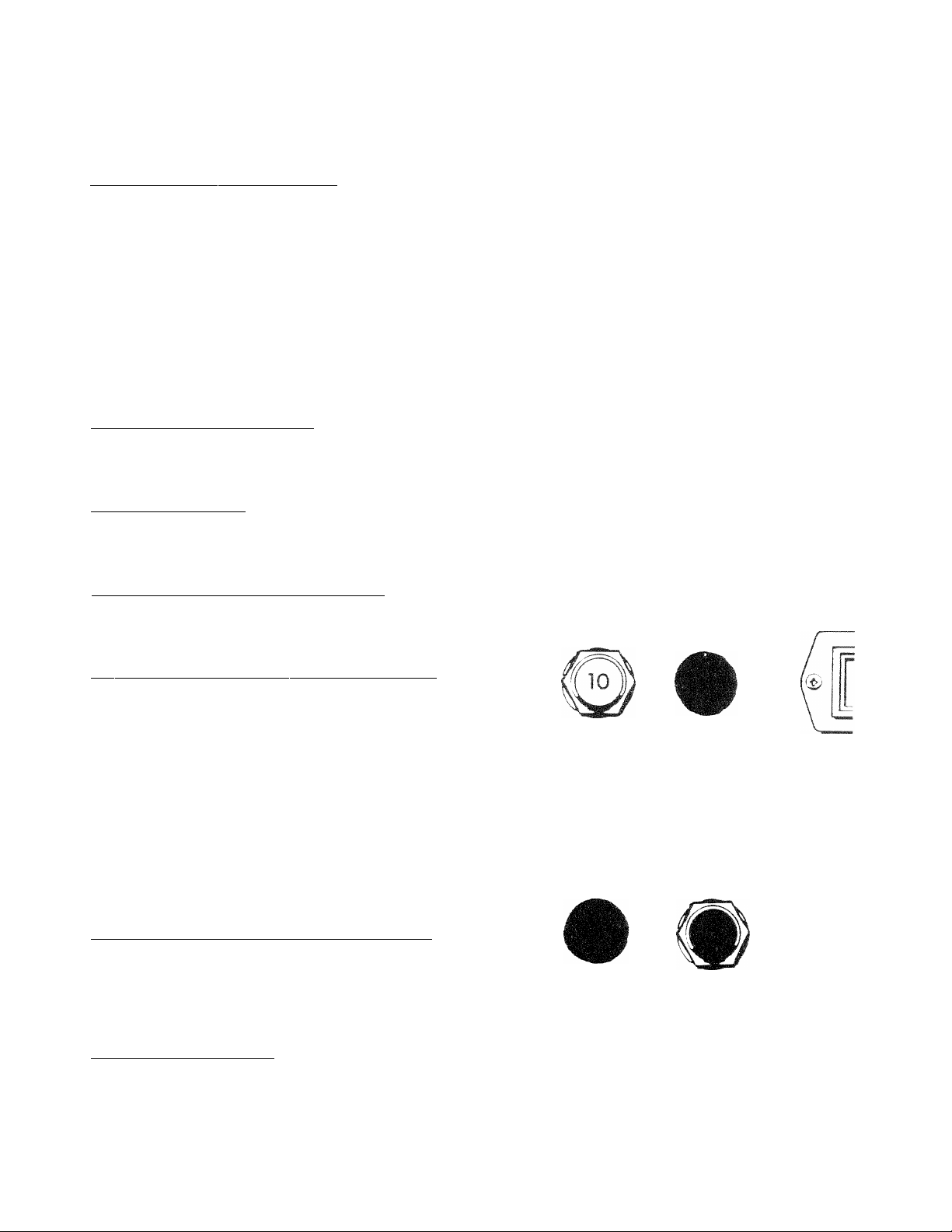
OVERLOAD PROTECTION FOR ENGINE
D-C ELECTRICAL SYSTEM
Engine cranking, start up and running are controlled by
a solid state Engine Controller circuit board. Battery
voltage is delivered to that circuit board via 10 amp
circuit breaker and 14 amp in-line fuse. These overcurr
ent protection devices will open if circuit is overloaded.
CAUTION! If a circuit breaker opens or a fuse ele
ment melts, you should find the cause of the over
load before resetting the circuit breaker or replacing
the fuse.
10 amp Circuit Breaker: If the circuit breaker opens
due to an overload, you cannot crank or start the engine.
The circuit breaker is a "push-to-reset“ type. For emer
gency shutdown, pull the circuit breaker open. Also see
"Generator Control Panel" on Page 5.
_
14 Amp Fuse: If the fuse element melts open, you
cannot crank or start the engine. If you must replace
the fuse, use only identical 14 amp fuse (Figure 9).
30 amp Fuse: The generator set battery is charged
during operation by a d-c alternator, driven by the en
gine. This 30 amp fuse protects the charging circuit
against overload. Should you need to replace the fuse,
use only an identical 30 amp fuse (Figure 10).
D. Every 100 hours or Once Each Month**
(whichever comes first)
1. Inspect cooling system.
2. Inspect exhaust system.
E. Every 6 months or Every 250 Operating Hours"
(whichever comes first)
1. Change engine oil and filter.
2. Check engine operation.
3. Inspect drive belts.
4. inspect electrical system.
5. Inspect and check battery.
6. Check engine governor setting.
7. Clean or replace fuel filters.
8. Inspect air cleaner/flame arrestor.
9. Clean the generator.
10. Check cooling system and coolant level.
11. Inspect exhaust system.
12. Inspect fuel system.
F. Once Annually or Every 500 Operating Hours"
(whichever comes first)
1. Check engine valve clearance.
2. Check engine compression and condition.
3. Check fuel injection timing.
4. Check/test fuel injection nozzles.
G. Once Every Two Years
____________________
________
STAR n.NG
C ! K C U i I
10 AMP
Figure 9 — 14 amp Fuse
batter'T'
CHARGING pre-heat
30 AMP 30 SEC. MAX
ENGINE
CON TROLlEFV
14 AM
ST/
1. Drain, flush and refill cooling system.
Figure 10 — 30 amp Fuse for Battery Charge Circuit
-10-
Page 13

CHECKING FLUID LEVELS
Check Engine Oil: Check the engine crankcase oil
level at least every 8 hours that you operate the unit, or
before every time you use it (Figure 11).
Make sure the generator is as level as possible.
Remove oil dipstick and wipe dry with a clean,
lintfree cloth.
Install oil dipstick, then remove again.
Oil should be at dipstick FULL mark. Never operate
the generator with oil level below dipstick ADD
mark. DO NOT FILL CRANKCASE ABOVE DIP
STICK FULL MARK.
Battery Fluid: Check battery electrolyte fluid at least
once weekly. Fluid should cover separators in all bat
tery cells. If fluid level is low, add distilled water to cover
tops of separators. DO NOT USE TAP WATER IN
BATTERY.
Engine Coolant: Check coolant level in coolant recov
ery bottle.
• Add the recommended coolant mixture as neces
sary.
• Periodically remove radiator pressure cap to make
sure the coolant recovery system is functioning
properly. Coolant should be at bottom of radiator
filler neck. If coolant level is low, inspect gasket in
radiator pressure cap. Replace cap, if necessary.
To have pressure cap tested, contact an authorized
Generac Service Facility. Inspect cooling system
and coolant recovery system for leaks.
INSPECT GENERATOR SET
Once each week inspect the generator set. Look for
fuel, oil coolant leaks. Check for missing or loose nuts,
bolts and other fasteners. Check for damage. If unitis
dirty, it may be cleaned with a damp cloth or soft brush.
Inspect the exhaust system. NEVER operate the gen
erator with a defective exhaust.
INSPECT COOLING SYSTEM
Inspect the entire cooling system once each month or
every 100 operating hours, whichever occurs first.
Check for leaks, condition of hoses, tightness of clamps.
CHANGING ENGINE OIL
Refer to PERIODIC MAINTENANCE SCHEDULE for
engine oil and filter change frequencies. You should
also change generator engine oil before placing the
vehicle into storage.
Drain the oil while engine is still warm from running,
which means warm up the engine, shut it dov^n and
drain immediately as follows (Figure 12 ):
1. Remove OIL DRAIN HOSE from its retaining dip.
2. Loosen and remove OIL DRAIN HOSE CAP. Drain
oil completely into suitable container.
Figure 12 — Changing Engine Oil
-11 -
Page 14

3. When all oil has drained, insiail and tighten OIL
DRAIN HOSE CAP.
4. Turn OIL FILTER counterclockwise and remove.
Dispose of old filter.
5. Apply a light coating of engine oil to seal of new oil
filter, install FILTER and tighten bv hand only. DO
NOT OVERTIGHTEN.
6. Remove OIL FILLER CAP. Add recommended oil
(see SPECIFICATIONS). DO NOT OVERFILL
ABOVE THE DIPSTICK "FULL" MARK. Crank
case oil capacity is 3.7 U.S. quarts (3.5 liters).
CAUTION! After refilling the crankcase with oil,
always check oil level on dipstick. NEVER OPER
ATE ENGINE WITH OIL BELOW THE DIPSTICK
"ADD" MARK.
7. Start engine and check for oil leaks.
COOLANT CHANGE
Every two years, the cooling system should be drained,
flushed and refilled by an Authorized Service Facilty.
See SPECIFICATIONS for cooling system recommen
dations.
MISCELLANEOUS MAINTENANCE
Cleaning the Generator: Keep your standby genera
tor as dean and as dry as possible. Dirt and moisture
that is allowed to accumulate on internal generator
windings have an adverse effect on insulation resis
tance.
Periodically clean generator exterior surfaces. A soft
brush may be used to loosen caked on dirt. You can
use a vacuum system or dry, low pressure air to remove
any accumulations of dirt, if the generator is housed
inside an all-weather enclosure, clean the enclosure
with a soft, damp cloth or sponge and water.
Once each year have the generator cleaned and in
spected by an Authorized Service Facility. That facility
will use dry, low pressure air to clean internal windings.
Parts inside the control console should be cleaned and
inspected at this time as well.
Finally, have the insulation resistance of stator and rotor
windings checked. If insulation resistances are exces
sively low, the generator may require drying.
Battery: All lead-acid storage batteries discharge when
not in use. Refer to specific instructions and warnings
that accompany your battery. If such information is not
available, observe the following precautions when han
dling a battery:
• DO NOT use jumper cables and a booster battery
to crank or start the generator engine.
• DO NOT recharge a weak batter/ while it is installed
in the generator. Remove battery from generator
and recharge in a well-ventilated area, away from
fuel vapors, sparks, heat or flames.
• Battery electrolyte fluid is an extremely caustic sul
furic solution that can cause severe burns. DO NOT
permit fluid to contact eyes, skin, clothing, painted
surfaces, wiring insulation, etc. If you spill any
battery fluid, flush the affected area with clear water
immediately.
• Always wear safety glasses, rubber apron and
gloves when handling a battery.
• Batteries give off explosive hydrogen gas while
charging. The gas can form an explosive mixture
around the battery for several hours after charging.
Any spark, heat or flames can ignite the gas'^and
cause an explosion which can shatter the battery,
causing blindness or other serious Injury.
PERIODIC REPLACEMENT PARTS
Part Name
Oil Filter
Radiator Cap
Air Cleaner Element
Fuel Filter
Generac Part No.
127-70939
46627
70941
69858
-12
Page 15

TROUBLESHOOTING
PROBLEM
Engine won’t crank.
POSSIBLE CAUSES REMEDY
1. 10 amp circuit breaker tripped.
2. 14 amp fuse blown.
3. Loose corroded or defective
battery cables.
4. Defective engine Start/Stop switch.
5. Defective starter contactor.
6. Defective starter motor.
Engine cranks but won't start.
1. Vehicle fuel shutoff valve is closed.
2. Out of fuel.
3. Fuel solenoid (FS) is defectcive
4. Fuel pump (FP) is defective.
5. Open Wire #14 from Engine Control C.B.
6. Clogged fuel filter or fuel line.
7. Engine mechanical parts failure.
8. Spark plugs defective.
Engine starts hard, runs rough.
1. Flame arrestor (air cleaner) plugged or
damaged.
2. Defective fuel pump.
3. Plugged fuel filter or fuel line.
4. Water in fuel.
Engine starts, shuts down
when Start/Stop switch is
released.
1. Engine oil level is low.
2. Engine is overheated.
3. Defective Low Oil Pressure Switch
4. Defective Coolant Temperature Switch
5. Defective Engine Controller circuit board.
1. Reset circuit breaker
2. Replace fuse.
3. Tighten dean or replace
as necessary.
4. Replace Start/Stop switch.
5. Replace contactor.
6. Replace starter motor.
1. Open valve.
2. Replenish fuel tank.
3. Refplace solenoid.
4. Repair or replace fuel pump.
5. Reconnecfwire.
6. Replace if clogged.
7. Repair or replace parts.
8. Clean, regap or replace plugs.
1. Clean or replace as needed.
2. Replace or repair fuel pump.
3. Replace filter; unclog fuel line.
4. Drain tank and refill.
1. Check oil and add oil as needed,
2. Check cooling system for leaks.
3. Replace switch.
4. Replace switch
5. Replace circuit board.
Start/Stop Switch at STOP,
engine continues to run
1. Defective Start/Stop switch.
2. Open/disconnected wire #18 between
Start/Stop switch & Engine Controller C.B.
3. Open/disconnected wire #0 between
Start/Stop switch & Engine Controller C.B.
4. Defective Engine Controller circuit board
No a-c output from generator.
1. Check 15-amp circuit breaker.
2. Check vehicle circuit breaker & fuses.
3. Transfer switch set to NORMAL position
4. Generator internal failure.
1. Replace switch.
2. Reconneci/close wire.
3. Reconnect/close wire.
4. Replace board.
1. Reset to ON or CLOSED.
2. Reset and replace, if necessary,
3. Set to GENERATOR position.
4. Take generator to Authorized
Generac service facility.
- 13 -
Page 16

- CIRCUÍ г BREAKER 30A.3SA
- CiRCUíT BREAKER (iOA)
- CiRCUir BREAKER (5A)
- RELAY 02v) ТРОТ
relay (12v) DPOT
- DIODE 600V, 6АЫР
- DiOOE 600V, 6AMP
“ DC alternator
FUSE И AMP SEE
FUSE 30A
FUEL PUMP
FUEL SOlENOlD
GROUND
HIGH WATER TEMP SWITCH
HOURME TER
LOW OIL PRESSURE SWITCH
preheat contactor
RESISTOR 10 OHM, 5 WATT
STARIER
START contactor
PREHEAT SWITCH
SWITCH START/STOP
SENSE transformer
id
О
P
Z2
00
OJ
o>
tvi
CO
2
z
о
g
>
Q
33
>
T3
I
Ш
о
о
Q
m
z
m
WIRE POSITION 1
IS GROUND.
WIRE POSITION 2
TO 1 WILL START
UNIT.
WIRE POSITION 6
TO 1 WILL LIGHT
A RUN LAMP.
WIRE POSITION 3
TO 1 WILL STOP
UNITWIRE POSITION 4
TO 5 WILL START
PREHEAT.
>
О
Page 17

ELECTRICAL SCHEMATIC — NP-80D GENERATOR
DCA-DC ALTERNATOR
DP£ -EXCiTATiON WINDING
n -FUSE UAMP SFE
F2 -FUSE 30A
FS -FUEL SOLENOiD
FP -FUEL PUMP
HM -HOURMETER
HWT-HiGH water temp switch
LOS-LOW Oil PRESSURE SWITCH
PHC -preheat contactor
R2 -resistor 10 OHM. 5W
s -starter
SC -START contactor
Sw -PREHEAT S'WITCH
SW] -SWITCH, START/STOP
T1 -SENSE transformer
TP -thermal PROTECTOR
CONNECTION OPTIONS
- 15 -
Page 18

EXPLODED VIEW — ENGINE COMMON PARTS
Drawing No. 81982
-16
Page 19

_______
Drawing No. 81982
REPAIR PARTS LIST — ENGINE COMMON PARTS
ITEM
PART NO.QTY.
1 81932
2
3
4
5
6
35586
81946
81947
55934
22302
7 51755
8
9
10
72501
43107
81942
11 49813
12
13
14
15
16
17
18
19
20
21
22
23
24 72573
25
26
27
28
29
30
75674
81975
357-70939
42909
81936
70941
42574
60108
26208
25507
42568
81951
70928
51716
22152
81939
65852
71912
DESCRIPTION
1 1.0 Liter Diesel Engine
6
1
1
1
1 -3/4" Hose Clamp 32 69860-B
Upper Radiator Hose
Lower Radiator Hose
Hose Retainer 35 70936
4 M10 Lock Washer
2
Ml 0-1.5 X 16mm Capscrew37
2 Engine Support
4
1
6
1
1
1
1
1
M8-1.25 X 25mm Capscrew
Exhaust Manifold
M6-1.0 Hex Nut
Exhaust Outlet Gasket42
Flex Exhaust Outlet 43
Manifold Gasket
M8-1.25 X 30mm Capscrew
Air Intake Chamber
1 Air Filter
1
1/8" NPT-1/8-28 Adaptor
1 Oil Pressure Switch
1
1
1
1
M8 Shakeproof Washer50
Ml 0 Washer
M8-1.25 X 20mm Capscrew
Engine Wire Harness
1 Oil Drain Fitting
1
1
5
1
1
1
Hose Clamp
M5-0.8 Hex Nut
M5 Lock Washer
Oil Drain Bracket 58
Oil Drain Hose Clip
M5-0.8 X 8mm Screw
ITEM
PART NO.
31 69811
33 74018
34
74070
36 71956
22129
38 72553
39
40
41
49813
26850
22158
42568
22097
44 24114
45 56739
46
47
48
49
75763
77745
40173
49340
74024
51 43146
52 45757
53
54
74069
74009
55 39253
56
57
72564
71910-A 1
45771 4
59
46233
60 50190
QTY. DESCRIPTION
1 Drain Cap
1 Oil Drain Hose
4
4
M12 Lock Washer
Ml2-1.25 X 40mm Capscrew
2 Vibrator Mount
2
Special Washer
12 M8 Lock Washer
2
4
M8-1.25 X 50mm Capscrew
M6-1.0 Hex Nut
2 M6 Shakeproof Washer
4 No. 10-32 Hex Nut
4
M6-1.0 X 20mm Capscrew
6 M6 Lock Washer
4
5/16"-18 Hex Nut
2 12 volts Solenoid
2 Red Vinyl Boot
2 Starter Cable
1
1
1
1
Hose Clamp
Elbow (barb to thread)
Fuel Pump Assembly
M6-1.0 X 10mm Capscrew
1 M10-1.0 x 25mm Capscrew
2
2
6
1
M10-1.5 X 40mm Capscrew
M10-1.5 Hex Nut
M8-1.25 X 20mm Capscrew
Fuel Filter Bracket
Lifting Bracket
M8-1.25 Hex Nut
1
1
3/8-30-1/8 V-Beit
Special M8 Fiat Washer
-17-
Page 20

EXPLODED VIEW — ENGINE BLOCK
Drawing No. 82961
18
Page 21

Drawing No. 82961
EXPLODED VIEW — ENGINE BLOCK
ITEM
1 139-70939
2
12
13
14
15
16
17
18
19
20
21
22
23
24
25
28
29
30
31
32
33
PART NO. QTY.
140-70939 20
143-70939
144-70939
145-70939 1
146-70939
182-70939
183-70939
184-70939
185-70939
186-70939 1
145-70939
168-70939 1
187-70939
188-70939
189-70939 1
26073-A 1
244-70939
245-70939
246-70939
145-70939
122-70939 1
DESCRIPTION
1
1 DIPSTICK TUBE
2 0-RING
1
1
1
1
1
2
3
1
1 0-RlNG
1
1
2
OIL PAN
BOLT
BOLT
DIPSTICK
ROCKER COVER GASKET
ROCKER COVER GASKET
ROCKER COVER
OIL STOPPER
SCREEN
BOLT
GASKET
NUT
CAP
O-RING
1/4" PIPE PLUG
TUBING
SUCTION FILTER
BOLT
GASKET
¡9-
Page 22

EXPLODED VIEW — CRANKSHAFT, PISTON & FLYWHEEL
Drawing No. 75679
ITEM
1
2 194-70939
3
4 196-709391
5
6
7
PART NO. QTY.
143-70939
195-70939
226-70939
197-709391 Bearing Holder
200-709391
8. 201-70939
9 198-709396
10
11 202-709393
199-709396 Dowel Pin 21
203-70939AR 0.25mm U.S. Bearing
204-70939AR
12 205-709393
206-70939AR 0.25mm U.S. Bearing
207-70939
13
208-709392
14 204-709392
15
210-709391 Bolt
DESCRIPTION ITEM
1 Crankshaft Assembly 16
1 Crankshaft Gear
1
1 Spring Pin
1
Key 216-70939
Dowel Pin
Bearing Holder
17
18 217-709393 Piston Pin
Bearing Holder 19
Bolt 20
Standard Bearing
22
23
0.50mm U.S. Bearing24
Standard Bearing
AR
0.50mm U.S. Bearing
28
Thrust Washer 30
Bolt
- 20-
PART NO.
QTY.
DESCRIPTION
214-709393 Standard Piston Assembly
215-70939
211-70939
212-70939
213-70939
218-70939
219-70939
220-709393
221-70939
222-70939
223-709396
224-70939
225-70939
230-70939
231-70939
AR
AR
3
AR
AR
6 Snap Ring
3 Connection Rod Assembly
6
6
AR
AR
1
1 Nut
Piston Assembly - 0.5mm O.S
Piston Assembly - 1.0mm O.S
Standard Piston Ring Set
Piston Ring Set - 0.5mm O.S.
Piston Ring Set - 1.0mm O.S.
Bushing
Connecting Rod Bolt
Nut, Connecting Rod Bolt
Standard Bearing
Bearing — 0.25mm U.S.
Bearing —0.50mm U.S.
Pulley
U.S. — UNDERSIZE
O.S .— OVERSIZE
Page 23

Drawing No. 75678
EXPLODED VIEW — CYLINDER HEAD
ITEM
1
2
3
4 149-70939
5
6
7
8
9
10
11 157-70939
12
13
14 161-70939
15
16
17
18
19
20
21
22
PART NO.
147-70939
148-70939 6
447-70939
150-70939
151-70939
152-70939
153-70939
154-70939 6
155-70939
156-70939
158-70939
159-70939
160-70939
162-70939
163-70939
164-70939
165-70939
60108
167-70939
168-70939
169-70939
QTY.
1
3
2
3
3
3
3
6
12
6
1
1
11
3
2
2
1
2
1
1
4
1
DESCRIPTION
Cylinder Head Assembly
Expansion Plug
Expansion Plug
Expansion Plug
intake Valve
Exhaust Valve
Valve Guide Seal (Exhaust)
Valve Guide Seal (Intake)
Spring
Retainer
Key
Cap
Cylinder Head Gasket, 1.2mm thick
Cylinder Head Gasekt, 1.3mm thick
Bolt
Bolt
Lifting Eye
Bolt
Tubing
Bolt
Oil Switch
Thermo-Switch
Gasket
Washer
21 -
Page 24

EXPLODED VIEW — CAM SHAFT
Drawing No. 75677
ITEM PART NO.
1 232-70939
2
3
4 234-70939
5
6
7 237-70939
8
9
10
11 241-70939
12 242-70939
13
233-70939 1 Camshaft Gear
195-70939 1 Key
235-70939 3 Spacer
236-70939
238-70939
239-70939
240-70939
243-70939
QTY.
1
1
1
1
1
1
1 Bolt
1
1
1 Nut
DESCRIPTION
Camshaft Assembly
Gear
Bail Bearing
Slider
Plate
Tachometer Shaft
Bolt
Gasket
r2 -
Page 25

Drawing No. 75676
EXPLODED VIEW — CYLINDER BLOCK
ITEM
1
2
3
PART NO.
100-70939
447-70939
101-70939
4 102-709392
5 103-70939
6 104-70939
7 105-70939
8 106-70939
9
10
11
107-70939
108-70939
109-70939
110-70939
111-70939
12 112-70939
13
14
15
16
113-70939
114-70939
115-70939
116-70939
QTY.
1
1
1
DESCRIPTION
Complete Cylinder Block
Expansion Plug 18
Expansion Plug
Expansion Plug
2
1
Expansion Plug 21 121-709391
Expansion Plug
4 Plug
4 Plug
1
1
1
1
1
1
1
1
2
2
Idle Gear Shari
Bushing
Bushing — Standard
0.25mm U.S. Bushing28 128-70939
0.50mm U.S.Bushing
Ball Bearing
Expansion Plug
Ball Bearing mm = millimeter
Dowel Pin U.S. = Undersize
Dowel Pin
ITEM PART NO.
17
117-709392 Dowel Pin
QTY. DESCRIPTK
118-709392 Spring Pin
19
20 120-70939
22 131-70939
23 123-70939
24
25 125-70939
26
119-709392
1
1
1
124-709391 Drain Cock
1
126-709391
27 127-709396 Tappet
6
29
129-70939
30 130-70939
1
1
- 2i
Stud
Stud
Stud
Snap Ring
Oil Seat
Connector
Oil Filter
Push Rod
Relief Valve
0-ring
Page 26

EXPLODED VIEW — OIL PUMP COMPONENTS
Drawing No. 75682^
■X
\
•) I.. \ ^.
I r-\ '
1 \ -7^
• ‘ 7 .x, (— f > V
H ■ \\ u A' ^ v'' ^X
.. 'i ^ Xf ■,X'' A"-i' A//A^
y \v73 Aa
Xv^^ 1: AA«
; •’"K
’ i r
A
A. I
ITEM
1 250-70939
2
3 251-70939
4 253-70939 1
5 254-7093S
6
7
8
9
10
11 263-70939
12 264-70939 3
PART NO.
252-70939
255-70939 AR
531-70939 AR 0.15mm Shim
532-70939 AR
258-70939 AR 0.50mm Shim
259-70939
260-70939
261-70939 1 Snap Ring
262-70939
AR — AS REQUIRED
DESCRIPTION
1
1
1
1 Oil Pump Cover
1
1 Collar
1 Front Plate
1 Gasket
Idler Gear Assembly
Spring
Thrust Washer
Rotor
0,1mm Shim
0.2mm Shim
Spring
Bolt
7
8
#
24
Page 27

__________
Drawing No. 75683
EXPLODED VIEW — ROCKER ARM ASSEMBLY
ITEM PART NO.
1
2
3
4
5
6
7
8
9
10
11
12
170-70939 1
171-70939
172-70939 3
174-70939 6
173-70939 6
175-70939
176-70939
177-70939
178-70939
179-70939
180-70939
181-70939
QTY.
3
3
1
2
2
1
3
3
DESCRIPTION
Rocker Arm Assembiy
intake Rocker Arm
Exhaust Rocker Arm
Nut
Stud
Rocker Arm Bracket
Rocker Arm Shaft
Spring
Screw
Spring Pin
Nut
Stud
25 -
Page 28

EXPLODED VIEW — FUEL SUPPLY
Drawing No. 75693
TO FUEL TANK
ITEM PART NO.
1
2
3 47290
661-70939
69858
4 52221
5
6
7
8 74808
9
40173
378-709392
379-709391
52233 2
10 39450
TO INJUCTION PUMP
TO FUEL FtiMP
QTY. DESCRIPTION ITEM PART NO. QTY. DESCRIPTION
1
1
Fuel Filter Support
Fuel Filter
1 3/8“ dia. X 12-1/2" Hose
1 5/16" dia. X 6-1/2" Hose
4 No. 5.5 Hose Clamp
Gasket 15
Banjo Fitting
1
Fuel Bleed Fitting
1/8" NPT Tee (brass)18
2
1/8" NPT X 3/16“ 90-degree
11
30096
12 68736 1 3/16" dia. X 1/2" Hose
13 68736 1 3/16" dia. X 7-3/4" Hose
14
74823
74819 1 Fuel Bleed Fitting
16
17
651-709395 Fuel Bleed Gasket
662-70939
663-709392 Banjo Type Fitting
2
1/8" NPT X 3/16" Barbed
Straight Fitting
4
Clamp
2 Hollow Bolt
Barbed Fitting
- 26
Page 29

Drawing No. 82962
EXPLODED VIEW — WATER PUMP
ITEM
1
2 266-70939
3
4
5
6 270-70939
7 271-70939 1 Bolt
8
9
10
11 275-70939
12
15
PART NO. QTY.
265-70939
267-70939
268-70939
269-70939 3 Gasket
272-70939
273-70939
274-70939
247-70939
284-70939
1 Water Pump Assembly
1
1 Thermostat
1
1
1 Gasket
1
1 Bolt
1
1
1
DESCRIPTION
Plug
Spring
Set Plate
Bolt
Nut
Pulley
Bolt
-27-
Page 30

EXPLODED VIEW — INJECTOR PUMP
Drawing No. 75686
ITEM PART NO.
1
316-70939
2
317-70939
318-70939
319-70939
320-70939
3
298-70939
4
321-70939
5
322-70939
6
323-70939
7
324-70939
8
9
10
11
12
13
14
325-70939
326-70939
327-70939
328-70939
329-70939
330-70939
331-70939
QTY.
1
AR
AR
AR
AR
2
2
3
3
DESCRIPTION ITEM
Injector Pump Assembly15
0.2mm Shim
0.3mm Shim 17
0.5mm Shim
1.0mm Shim
Nut
Bolt
Gasket
Insert
3 Cap
3
Injector
1 Tubing
1 Tubing
1 Tubing
1 Tubing
1
1 Bolt
Clamp
PART NO. QTY.
298-70939 1
16
332-70939 3
333-70939 1
18
334-70939
19
335-70939
20 264-70939
21
336-70939 1
22
337-70939 2 Washer
23338-70939
24
339-70939
25
240-709391
26341-70939
27
342-70939 1
28343-70939
29344-70939
AR — AS REQUIRED
28
DESCRIPT
Nut
Glow Plug
Connector
1
1
2
Gasket
Cover
Bolt
Sensor
2
1
Nut
Bolt
Lock Wire
1
Solenoid
Washer
1
1
Washer
Screw
Page 31

EXPLODED VIEW — TIMING GEAR HOUSING AND GOVERNOR
iTEM PART MO.
1 285-70939
2
3
286-70939
287-70939
4 307-70939
5
6
7 310-70939
8 314-70939
9
10
11
12 297-70939
13
14 299-70939
15
16 301-70939
17
18
19
20
21
22
23
24
308-70939
309-70939
315-70939
180-70939
296-70939
298-70939
300-70939
540-70939
282-709395 Bolt
288-70939
274-70939
311-70939
304-70939
305-70939
306-70939
QTY.
1
1
1
1 Spring
1 Washer
2
1 Stop Lever
2
1
4
1 Governor Lever
1
4
1
1 0-Ring
1
3
1
4
5 Bolt
1
1
1 0-Ring
DESCRIPTION
Timing Gear Housing
Spring Pin
Gasket 27
Nut 30
Cover 32
Gasket
Nut
Bolt
Nut 37
Shaft
Snap Ring
Bolt
Oil Seal
Bolt
Arm
Snap Ring
ITEM
25 289-70939
26
28
29
31
33
34
35
36
38 71944
39
40
41
42
43 537-70939
44
45
46
47
PART NO.
QTY.
290-70939
291-70939
136-70939
292-70939
313-70939
293-70939
294-70939
295-70939
291-709391
302-70939
271-70939
303-70939
660-70939
3 Boit
2 Bolt
1 Screw
1
534-709391
535-70939
1
536-70939
539-70939
1
1
188-709391
541-70939
538-70939
1
3
1
1
1
1 Washer
1
1
1
1
1
1
1
DESCRIPTION
Governor Lever Assembly
Tension Lever
Snap Ring
Cotter Pin
Spring
Spring
Arm
0-Ring
Snap Ring
Bracket
0-Ring
0-Ring
Spacer
Gasket
Holder
0-Ring
Cap
Bolt
Nut
Page 32

EXPLODED VIEW — RADIATOR
Drawing No. 83294
• INDICATES
UK'aTION of
WELD STUDS
ITEM PART NO. QTY.
1
2
3 80245
4
5 82603
6 83058
7 81977-A 2 FOAM PAD
8
9
10
83098
83057
81905
81947
81946
82605
11 22097
12 49813
13 66831
14
15
35586
45757 4
16 42568
17 56892
18
19
20
21
22
23
58442 2
46627
52250 5 ft. FOAM PAD - 3/4" X 1" WIDE
50832
81976
51787
1 ASSEMBLY, BASE
1 RADIATOR, CROSS FLOW
1
1
1
1
1
1
1
15
11
2 RIVET, POP
4
7
6 CRIMPTITE, No. 10-32 x 3/8"
1
1
1
6 CAPSCREW, HEX HEAD - M4-0.7 x 16mm
DESCRIPTION
BLOWER HOUSING
FAN, ENGINE
RING, FAN INLET
BRACKET, RADIATOR MOUNTING
HOSE, LOWER RADIATOR
HOSE, UPPER RADIATOR
PLATE, BLOWER HOUSING
LOCK WASHER - M6
NUT, HEX-M6-1.0
CLAMP (WORM TYPE)
CAPSCREW, HEX HEAD - M6-1.0 x 25mm
CAPSCREW, HEX HEAD - M6-1.0 x 20mm
CRIMPTITE, 1/4--20X 1/2"
CAP, RADIATOR
DRAIN COCK-V8 NPT
HUB, FAN
24 22152 6 LOCK WASHER - M4
25 22473
26
29451
11
5 ft.
FLAT WASHER-M6
FOAM TAPE - 1/8" X 1/2"
-30-
Page 33

_________________
Drawing No. 75685
EXPLODED VIEW — D-C ALTERNATOR
ITEM
1
2
3
4
5
6
8
9
10
11
12
PART NO.
QTY.
77909
74829
72545
74007
74069
51753
277-70939
345-70939
349-70939
346-70939
348-70939
DESCRIPTION
1
1
Adjusting Plate 13 349-70939
M8-1.25 X 30mm Bolt
ITEM PART NO. QTY. DESCRIPTION
14
352-70939
1 Lock Washer 15 353-70939
1
1
2
1
1
1
1
1
M10 Flat Washer
Ml 0-1.5 X 40mm Capscrew
M6-1.0 X 40mm Bolt 18 350-70939
Alternator Assembly 19 351-70939
Flywheel
Bearing
Plate Assembly
Stator
16 354-70939
17
355-70939
20 137-709391 Lock Washer
21
280-709391 Washer
22 356-709391
23 74827 1 M8 Flat Washer
24
70005 2
-31 -
1 Bearing
1
1
1
2
1
1
Coupler
Clamp
Screw
Screw
Cap
Nut
Collar
M6 Lock Washer
Page 34

J2
Page 35

_________________
Drawing No. 83699
REPAIR PARTS LIST — CONTROL BOX
ITEM PART NO.
1
2
3
4
5
6
7 22220
8 22155
9
10
11
12 81903
13
14 67680
15
16
17
18
19
20
21
22 74076
23
24
25
26 42568
27 26850
28
29
30 45770
31
32
33
34
35
36
37
39
40
41
42 55440
44
45
46
47 49813
48
49
23484-F
32300
81904
22668
55927
75207-B
25433
39271
48512
71938-A
83635
74969
36900
22155
23762
81902
81884-D
77604
75208
55920
22152
23897
*77744
74041
51718
43184
51715
80882
72566
70325
22097
51716
*82617 1 Panel Wire Harness
*81951
82737
22188
22473
QTY.
2 SB-1000-12 Snap Bushing
1
1
1 30-amp AGC Fuse
1 14-amp SFE Fuse
1 10-amp DC Circuit Breaker
1 No. 6 X 7/8" long Round Head Machine Screw
1 No. 6 Lock Washer
1 No. 6-No. 14 AWG Solderless Lug
1
1
1 Control Box
1 DC Regulator
1 AC Regulator Assembly
1
1 35-amp Circuit Breaker
4 No. 6-32 X 1/4" Phillips Pan Head Machine Screw
4 No. 6 Lock Washer
1 No. 10 External Lock Washer
1
1 Control Pane! Decal
2
1
1
1
2
2
10
8
8
1
1 M5-0.8 X 20mm Phillips Pan Head Machine Screw
2
2
2
4 No. 6 X 5/8" Self-tapping Screw
4 Spacer Nut
1 Engine Controller Assembly
6
2
2
1 Engine Wire Harness
4
4
1
8
DESCRIPTION
30-amp AGC Fuse Hoider
14-amp SFE Fues Holder
3/4" Greenlee, 90-degree Conduit Clamp
5-amp Circuit Breaker
AC Transformer
Control Panel
M3-0.5 X 10mm Pan Head Machine Screw
Hour Meter
Start/Stop Switch
Preheat Switch
M6-1.0 X 20mm Hex Head Capscrew
M6 External Lock Washer
M5 Lock Washer
M5 Flat Washer
M5-0.8 X 10mm Hex Head Capscrew
Customer Leads
M4-0.7 X 10mm Pan Head Machine Screw
M4 Lock Washer
M4-0.7 Hex Nut
M6 Lock Washer
M5 Hex Nut
M5-0.8 X 25mm Hex Head Capscrew
Vibration Dampener
M6-1.0 Nut
No. 6 Hex Nut
M6 Flat Washer
NOT SHOWN
jj
Page 36

EXPLODED VIEW — GENERATOR
Drawing No. 81983
Qs CM
0^
34
CM
\ ,
\
/
^ / \
/
\
!
\/
CO
\
1
i-
o
F5
Page 37

Drawing No. 31983
REPAIR PARTS LIST — GENERATOR
ITEfyi
1 24488
2 24911
3
4
5
6
7
8
9
10
11
12
13
14
15
16
17
18
19
20
21
22
23
24
25
26
27
28
29
30
31
32
33
34 BM45761
35
36
37
38
39
40
41
42
PART NO.
BN45761
81931
47248
81956
81955
45770
22152
81974
74066
22302
81952
81900
81192
42911
81901
82737
22145
59450
75763
70954
81929
39253
70936
71956
22129
72553
45771
A-24044-A
23877-D
25105
82626
52858
81991
22097
22127
22237
42909
29107
25155
QTY.
4
4
4
1
1 45M Ball Bearing
1
1
10
6
4
4
4
1
1 Ring Fan
1
4
1
4
4
2
1
1
1
4
2
2
8
2
8
4
2
4
1
4
4
1
1
1
4
2
1
1
DESCRIPTION
No. 8 X 5/8“ Taptite Screw
No. 8 X 3/8" Taptite Screw
M8-1.25 X 160mm Stud
15" RV Rear Bearing Carrier
15" RV, 2.5L ASM Rotor
15" RV, 2.5L ASM Stator
M5-0.8 X 10mm Hex Head Capscrew
No. 10 Lock Washer
M8 X 20mm Hex Flange Bolt
M10-1.25 X 30mm Hex Screw
M10 Lock Washer
15" RV, 15M Flex Plate
15" ISM Flywheel Mach.
M10-1.5 X 30mm Hex Head Capscrew
Air Ring Baffle
Vibration Mount
5/16-M8 Fiat Washer
5/16-18 X 1-1/4" Hex Head Capscrew
Battery Cable Boot
Starter Motor
15", ISM 1L Engine Adaptor
M8-1.25 X 20mm Hex Head Capscrew
Vibration Isolator
5/16-M8 Flat Washer
5/16-M8 Lock Washer
M8-1.25 X 60mm Hex Head Screw
M8-1.25 Hex Nut
Brush
Brush Holder
No. 6-32 X 1/4" SIMS
Brush Cover
M8-1.25 X 30mm Stud
M8-1.25 Hex Nut Flange
Red Wire Assembly
1/4" Lock Washer
1/4-20 Hex Nut
M10 Lock Washer
M8-1.25 X 30mm Hex Head Capscrew
Rubber Grommet
Clamp
-35
Page 38

NOTES
36
Page 39

ELECTRICAL FORMULAS
TO FIND
KILOWATTS (kW)
KVA
AMPERES
WATTS
NO. OF ROTOR
POLES
FREQUENCY
RPM
KNOWN VALUES
Volts, Current, Power Factor
Volts, Current
kW, Volts, Power Factor
Volts, Amps, Power Factor
Frequency, RPM
RPM, No. of Rotor Poles
Frequency, No. of Rotor Poles
1-PHASE
ExI
1000
ExT !
E X T X 1.71 X PF
1000
E.xIa L73
1000 ; 1000
kWxlOOO
kWx 1000
E i Ex 1.73 xPF
Volts X Amps
E X I X 1.73 X PF
.
2 X 60 X Frequency
RPM
RPM X Poles
2x60 i
2 X 60 X Frequency
Rotor Poles :
2 X 6flxFie,quency
RPM X Poles
2x60
2 X 60 X Frequency
Rotor Poles
3-PHASE
RPM
kW (required for
Motor)
RESISTANCE
VOLTS
AMPERES
E = VOLTS
Motor Horsepower, Efficiency
Volts, Amperes
Ohm, Amperes
Ohms, Volts
I = AMPERES
HP X 0.746 :
Efficiency
E :
I
IxR
1 ^
1 R
HP X 0.746
Efficiency
E
I
IxR
E
R
1
R = RESISTANCE (OHMS) PF = POWER FACTOR
Page 40

GENERAC’S 3-YEAR LIMITED WARRANTY
FOR NP SERIES RECREATIONAL VEHICLE GENERATORS
Generac warrants to the original purchaser that its generators will be free from defects in materials or
workmanship for the period set forth below from date of original purchase. During said warranty period,
Generac will, at its option, repair or replace any part which, upon examination by Generac or Generac
Authorized Distributors and/or Dealers, is found to be defective under normal use and service.
3-YEAR WARRANTY SCHEDULE
1. All NP Series generators used in a recreational vehicle shall be warranted from date of purchase
for a period of three (3) years or 2000 hours of operation, whichever occurs first. All parts, labor,
removal and reinstallation shall be covered for the first two years. Parts and labor on selected
generator and engine parts shall be covered during the third year or 2000 hours.
2. The drive train, belt and pulleys on NP series air-cooled generators shall be warranted against failure
due to defective materials or normal usage for the life of the generator. For the original owner, this
drive train warranty shall include parts and labor plus a $50.00 payment upon return of the failed
belt or pulley by the original owner. For succeeding owners, this power train warranty shall cover
belt or pulley parts only.
3. Rental units, demonstrators or commercial applications, such as construction or utility, are warranted
for one year or 2000 hours, whichever comes first.
All warranty expense allowances are subject to the conditions defined in the published
POLICIES AND PROCEDURES" manual.
THIS WARRANTY DOES NOT COVER;
Costs of maintenance, installation and startup.
Failures due to normal wear, accident, misuse, abuse, negligence or improper installation.
Products which are modified or altered in a manner not authorized by the manufacturer in
writing.
Incidental, consequential or indirect damages caused by defects in materials or workman
ship, or any delay in repair or replacement of defective parts.
Failure due to misapplication.
Telephone, telegraph, teletype or other communications expenses.
Living or travel expenses of persons performing service.
All transportation/travel expenses.
Rental equipment used while warranty repairs are being performed.
Overtime labor.
Starting batteries, fuses, light bulbs and engine fluids.
THIS WARRANTY IS IN PLACE OF ALL OTHER WARRANTIES, EXPRESS OR IMPLIED. SPECIF
ICALLY, GENERAC MAKES NO OTHER WARRANTIES AS TO MERCHANTABILITY OR FITNESS
FOR A PARTICULAR PURPOSE. Some states do no allow limitations on how long an implied warranty
lasts, so the above limitation may not apply to you. GENERAC'S ONLY LIABILITY SHALL BE THE
REPAIR OR REPLACEMENT OF PARTS AS STATED ABOVE. IN NO EVENT SHALL GENERAC BE
LIABLE FOR ANY INCIDENTAL OR CONSEQUENTIAL DAMAGES, EVEN IF SUCH DAMAGES ARE
A RESULT OF GENERAC’S NEGLIGENCE. Some states do not allow the exclusion or limitation of
incidental or consquential damages, so the above limitation may not apply to you. Buyeragrees to make
no claims against generac based on negligence.
‘GENERAC
This warranty gives you specific legal rights, and you may also have other rights, which vary from state
to state.
GENERAC CORPORATION, P.O. Box 8, Hwy 59 and Hillside Road, Waukesha, Wl 53187
Telephone (414) 544-4811 FAX (414) 544-4851
 Loading...