

Page 1

NP Series and Q Series
AIR-COOLED
Manual No. 91355
INSTALLATION
Manual
RECREATIONAL VEHICLE
GENERATORS
For Models Powered by Gasoline and LP GAS
CORPORATION
Revision 6 (10/6/97)
Printed in U.S.A.
Page 2

GENERAL SAFETY RULES
THE MANUFACTURER SUGGESTS THAT THESE “RULES” FOR SAFE OPERATION BE
COPIED AND POSTED IN POTENTIAL HAZARD AREAS OF THE RECREATIONAL VEHICLE.
SAFETY SHOULD BE STRESSED TO ALL OPERATORS AND POTENTIAL OPERATORS OF
THIS EQUIPMENT.
WARNING:
The engine exhaust from this product
contains chemicals known to the State
of Caiifornia to cause cancer, birth
defects, or other reproductive harm.
NOTICE TO INSTALLER
The Installation Instructions have been published by
Generac Corporation to aid in the installation of the
products described in this manual. Generac assumes
that installation personnel are familiar with the proce
dures for installing such products, or similar products
that Generac manufactures. Generac also assumes
that personnel have been trained in the recommended
installation procedures for these products and that
such training includes (a) use of common hand tools,
(b) use of special Generac tools, and (c) use of any
tools and/or equipment from other suppliers.
We could not possibly know of and advise the recre
ational vehicle trade of all conceivable methods, proce
dures or techniques by which to perform an installation.
We could not know of the possible hazards that might
result from each installation method, procedure or
technique. We have not undertaken any such wide
evaluation. Therefore, people who use a method, pro
cedure or technique that Generac does not specifically
recommend must first completely satisfy themselves
that their safety, the safety of the vehicle's occupants
and the products's safety is not endangered by the
method, procedure or technique selected.
Information, illustrations, specifications, etc., contained
in this Installation Manual are based on the latest infor
mation available at the time of publication. Every effort
has been expended to be sure that such data is both
accurate and current. However, the manufacturer
reserves the right to change, alter or otherwise improve
his product at any time without prior notice.
Gasoline is extremely FLAMMABLE and its vapors are
EXPLOSIVE. Do not permit smoking, open flame,
A
sparks or any source of heat in the vicinity while han
dling gasoline. Comply with all regulations governing
the storage and handling of gasoline.
Fuel lines must be properly installed, properly fas
tened and free of leaks. There must be no possibility
of gasoline vapors entering vehicle interior.
You are required to install an approved, flexible,
non-conductive fuel line between the generator fuel
connection point and rigid fuel lines.
If the generator can be equipped with a liquid
propane (LP) gas fuel system, install the unit so it
complies with all codes, standards and regulations
pertaining to such systems. LP gas is highly explosive.
The gas tends to settle in low areas where even the
slightest spark can ignite it and cause an explosion.
Do not allow gas vapors to enter the vehicle.
SAFETY RULES
Engine exhaust gases contain DEADLY carbon
monoxide gas. This dangerous gas, if breathed in suf
ficient concentrations, can cause unconsciousness or
even death. Install the exhaust system in strict compli
ance with applicable codes, standards and regula
tions. There must be no possibility for exhaust gases
entering the vehicle interior and endangering people
or animals.
The generator set produces dangerously high electri
A
cal voltage. Contact with bare wires, bare terminals,
etc., will result in extremely hazardous and possibly
lethal electrical shock.
All applicable electrical codes, standards and regula
tions must be strictly complied with in the installation
and use of this equipment.
The generator must be properly grounded (bonded)
to the vehicle chassis or frame.
If the vehicle electrical circuits can be powered by any
other source of electricity (such as a "dockside"
A
power receptacle), there must be no possibility of
connecting the different power sources to the vehicle
circuits at the same time. The "dockside" (utility)
power source must be positively isolated from the
vehicle circuits whenever the generator is operating.
Failure to isolate the vehicle circuits from the dockside power supply when the generator is running
may result in damage to the generator or serious
injury or death to dockside (utility) power workers
due to backfeed of electrical energy.
Never work on the equipment while standing in
water, while barefoot, or while hands or feet are
wet. Dangerous electrical shock will result.
Jewelry conducts electricity, which can cause danger
ous electrical shock. Remove all jewelry (such as rings,
watches, or bracelets) before working on this equip
ment.
The generator requires an adequate flow of air for
cooling and ventilation. Without sufficient cooling air
flow, the engine-generator quickly overheats, which
causes serious damage to the generator, a fire or an
explosion. Generator air inlet and outlet openings
must be provided in strict compliance with the manu
facturer's recommendations.
Never work on this equipment while physically or
mentally fatigued. Stay alert at all times.
Storage batteries give off EXPLOSIVE hydrogen gas
while charging. The battery used for cranking and
starting this generator should be installed in its own
ventecT compartment. Provide adequate ventilation
for the battery, to prevent explosive hydrogen gas
from accumulating.
Never insert any tool or other object through open
ings in the generator interior, even if the unit is not
running. You might seriously injure yourself or dam
age the equipment.
Staying alert and using "common sense" are major
measures for preventing accidents.
Page 3

TABLE OF CONTENTS
GENERAL SAFETY RULES
....................
inside cover
GENERAL INFORMATION
Purpose and Scope of Manual..................................... 2
Safety......................................................................... 2
Standards Booklets
.............
......................................... 2
Equipment Description ;............................................... 2
Engine Generator Operating Speed
Reconnection for Dual Voltage
...............................
.......................................
2
SPECIFICATIONS
Generator Specifications.............................................. 4
Engine Specifications................................................... 4
Recommended Fuel..................................................... 4
Fuel Consumption........................................................ 4
Recommended Engine Oil
...........................................
4
LOCATION AND SUPPORT
Generator Location
Generator Support
Suspended Mounting
......................................................
.........
............................................. 5
..................................................
5
5
Generator Restraint...................................................... 6
Swing Mount Generator Tray
.....
.................................
6
GENERATOR COMPARTMENTS
Compartment Size
Compartment Construction
Sound Insulation Materials
Compartment Roor Cutouts
.......................................................
..........................................
...........................................
.........................................
7
7
8
8
Acoustics’................................................................. 8-9
COOLING AND VENTILATION AIR
Generator Air Flow
.....................................................
10
Cooling Air Inlet Openings...........................................10
Compensating for Restrictions
......................
..............
11
Testing the Installation................................................11
GASOLINE FUEL SYSTEM..................................... 12
Fuel Tank....................................................................12
Generator Fuel Supply Line...,
....................................
12
PROPANE GAS FUEL SYSTEM
Parts Not Included in Fuel System
Some Important Considerations
Vapor Withdrawal
Primary Regulator..................................................................... 14
Gaseous Carburetion................................................................ 14
Fuel Supply Lines.......................................................................15
Excess Flow Valve
3
Leakage Tests.............................................................................15
EXHAUST SYSTEM
Mufflers and Spark Arrestors
Type of Exhaust System
Exhaust System Safety....................................................16-17
.......................................................................
.....................................................................
.................................................
...........................................................
..............................
.........................................
.............................................
..................................................
13
13
13
14
15
16
16
16
ELECTRICAL CONNECTIONS
Electrical Junction Box
Wiring............................................................................................18
Generator AC Connections
Conduit
.........................................................................................
Ground Fault Circuit Interrupters
Power Supply Cord....................................................................19
Isolating Different Power Sources
...........
..................................................18
......................................................
...........................................
................................
18
19
19
19-20
DUAL VOLTAGE RECONNECTION
Reconnection Procedure
.........................................................
21
BATTERY INSTALLATION
Recommended Battery
Battery Cables.............................................................................22
Battery Cable Connections
Battery Compartment
............................................................
......................................................
..............................................................
22
22
22
POST INSTALLATION TESTS
Before Initial Start Up
Initial Start....................................................................................23
Checking No-Load Voltage and Frequency
Testing Under-load............................................................23 - 24
Adjusting No-Load Frequency....^.........................
Voltage Regulator Adjustment
INSTALLATION CHECK LIST
.............
................................................. 23
................................................
..............
..........................
.........
24 -25
...................
23
25
26
ELECTRICAL FORMULAS.......................................27
MAJOR FEATURES AND DIMENSIONS
.........
28 - 29
Page 4
GENERAL INFORMATION
PURPOSE AND SCOPE OF MANUAL
These instâllation Instructions have been prepared
especially for the purpose of familiarizing installers
and owners of the applicable equipment with the pro
duct's installation requirements. Give serious consid
eration to all information and instructions in the
Manual, both for safety and for continued reliable
operation of the equipment.
Because of the different recreational vehicle models
and the variations between the models, it would be
extremely difficult, if not impractical, to provide
detailed instructions on every installation possibility.
For that reason, instructions and illustrations in this
manual are general in nature. Illustrations are not
intended to serve as detailed installation blueprints. .
The installation should comply strictly with all applica
ble codes, standards and regulations pertaining to the
installation and use of this product. If any portion of this
manual appears to be in conflict with such codes, stan
dards or regulations, the applicable codes, standards
or régulations must take precedence over the manual.
SAFETY
Before handling, installing, operating or servicing this
equipment, be sure to read carefully the “Notice to
Installer” and “Safety Rules” at front of this manual;
Comply with all SAFETY RULES to prevent death,
personal injury or damage to equipment and/or prop
erty. Stress safety to all installers, operators and ser
vice technicians who work on this equipment.
STANDARDS BOOKLETS
Installation, use and servicing of this equipment
should comply strictly with published standards, as
well as the manufacturer's recommendations. The fol
lowing standards booklets (latest révision) are avail
able from the sources indicated;
1. NFPA Standard 501C, “Standard for Recreational
Vehicles", available from the National Fire Protection
Association, Batterymarch Park, Quincy, MA 02269.
2. NFPA 70, “NFPA Handbook of the National Electric
Code", obtained from same address as Item 1.
3. ANSI Cl-1975 and ANSI 119.2-1975, available from the
American National Standards Institute, 1430 Broadway,
New York, NY 10018.
4. ANSI A119.2/NFPA 501C, available from the
Recreational Vehicle Association, 1896 Preston White
Drive, Reston, VA 22090.
EQUIPMENT DESCRIPTION
Instructions and information in this section pertain to
Generac “NP and “Q” air-cooled generators, more
specifically as listed below. These generators are
designed specifically for installing in recreational vehi
cles. They operate 120 volts, 1-phase, 60 Hertz, AC
electrical loads.
NOTE; All units, except the Q40G, may be recon
nected for a dual voltage output of 120/240 volts AC.
Series
Q-40G 4200 35.0
Q-55G/LP
Q-70G/LP 7000 58.3
NP-50G 5000 41.6
NP-50LP 4500 37.5
NP-66G/LP
Power (wattage) Max. Rated Current
at 120V
5500 45.8
6600
55
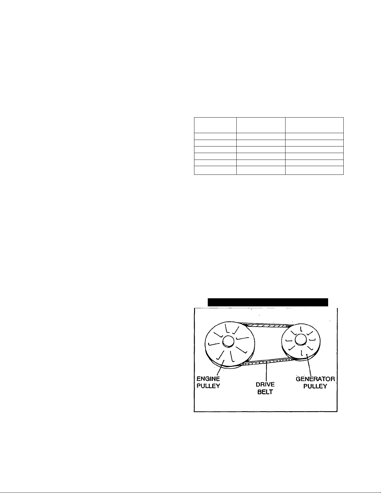
ENGINE GENERATOR
OPERATING SPEED
The generator’s revolving field (rotor) is driven by a 4cycle engine through a pulley and drive train arrange
ment (Figure 1). The generator supplies 120/240
volts AC at 60 Hertz when the rotor is operating at
3600 rpm. The drive train arrangement allows the
engine to operaté at a lower speed than the rotor.
Engine speed is held nearly constant by a mechani
cal, fixed speed governor as follows;
Series Q-40G
Series Q-55G/LP ......................
Series NP-50G/LP
Series NP-66G/LP
Series Q-70G/LP
Figure 1 — Typical Pulley and Drive Train
...........................
....................
....................
......................
2570 rpm
2570 rpm
2570 rpm ,
2700 rpm
.2570 rpm
5. California Administrative Code, Title 25, available from
the State of California, Documents Section, P.O. Box
1015, North Highlands, CA 95660.
6. CSA Electrical Bulletin 946, available from the Canadian
Standards Association, Housing and Constructions
Materials Section, 178 Rexdale Boulevard, Rexdale,
Ontario, Canada, M9W1R3.
— 2 —
Page 5
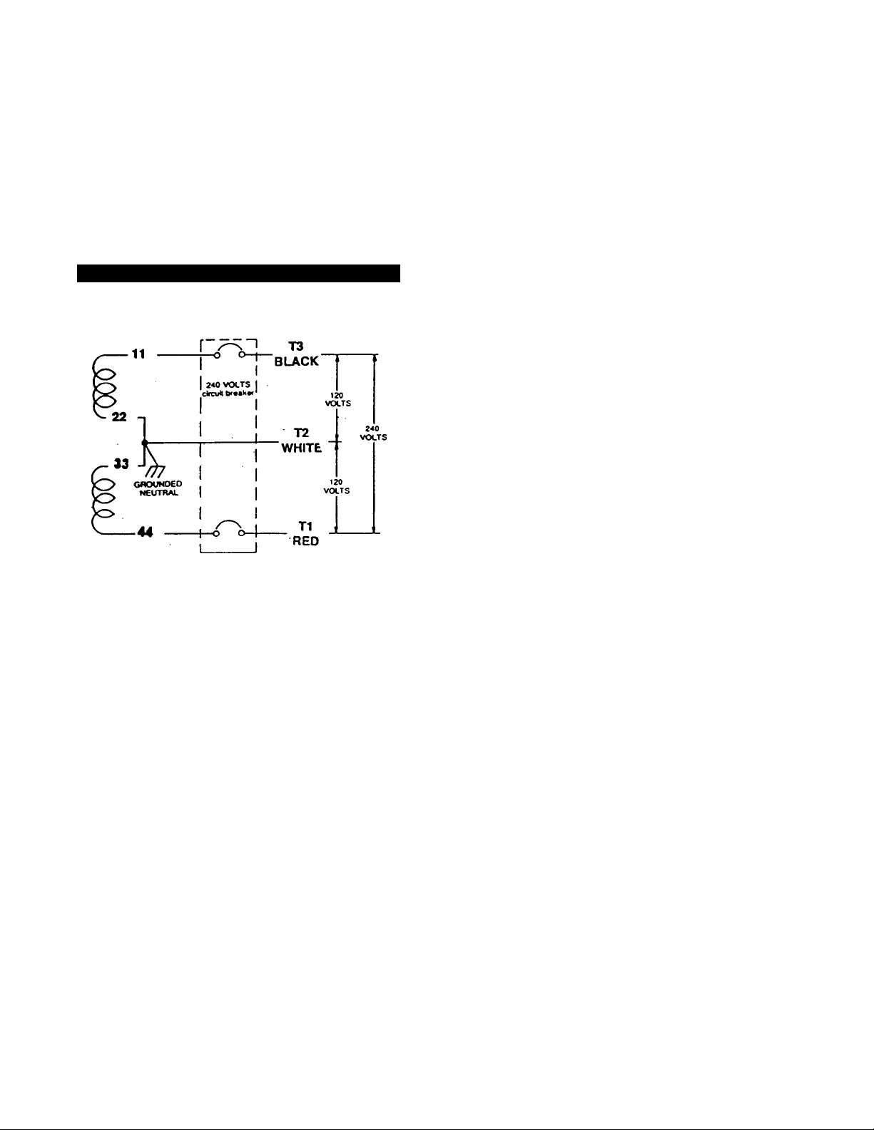
RECONNEaiON FOR DUAL VOLTAGE
You can reconnect the generators to supply a dual
voltage AC output, if desired. That is, units may be
reconnected to operate 120 and/or 240 volts, 1-
phase, 60 Hertz, AC loads. This is done by connect
ing the hwo stator AC power windings in series as it is
shown in Figure 2.
IMPORTANT: UNITS RECONNECTED FOR
120/240 VOLTS DUAL VOLTAGE OUTPUT WILL
NOT BE LISTED PER RVIA.
NOTE: The Q-40G can NOT be reconnected for a
dual voltage output of 120/240 volts AC.
Figure 2 — Reconnection for Dual Voltage Output
When reconnecting for dual voltage output, the
installer should replace the main circiut breakers
(CB1 and CB2) with a single adequately rated circuit
breaker. Rated maximum continuous load currents
are listed below:
• NP-50LP —18.8 AC amperes
• NP-50G — 20.8 AC amperes
• Q-55G/LP — 22.9 AC amperes
• NP-66G/LP — 27.5 AC amperes
• Q-70G/LP — 29.1 AC amperes
NOTE: This option is unavailabe on the Q40 model.
— 3 —
Page 6
GENERATOR SPECIFICATIONS
SERIES Q-40G NP-50G
Rotor RPM 3600 3600 3600
Rotor Poles 2 2
Engine RPM
Wattage*
Voltage*
Rated Amps*
Phase 1
Frequency
Weight 215 lbs.
Length
Width
Height
All units, except Q-40G, are reconnectable to
120/240 volts, dual voltage output. When reconnect
ed for dual voltage, units are not listed per RVIA.
V Rated maximum continuous current at 240 volts is
20.8 amps.
t Rated maximum continuous current at 240 volts is
22.9 amps.
t Rated maximum continuous current at 240 volts is
27.5 amps.
A Rated maximum continuous current at 240 volts is
29.1 amps.
* Rated maximum continuous current at 240 volts is
18.8 amps.
2570 2570 2570
4200 5000
120 120
35
60 60
41.6V 37.5* 45.8*
1 1 1 -
207 lbs. 207lbs.
ENGINE SPECIFICATIONS
Type of Engine
NP-50G/LP.......................................1 Cylinder, 4 Cycle OHVI
NP-66G/LP, Q-70G/LP
Q-40G, Q-55G/LP..................................V-Twin, 4 Cycle OHVI
Number of Cylinders
Q-40G, Q-55G/LP, NP-66G/LP, Q-70G/LP
NP-50G/LP ..................................................................................1
Valve Configuration...........................................Overhead Valves
Cooling Method
Rated Horsepower
NP-50G/LP
Q-40G
Q-55G/LP ...........................................................16 at 3600 RPM
NP-66G/LP
Q-70G/LP ...........................................................19 at 3600 RPM
Displacement
NP-50G/LP .........................................................................363CC
Q-40G
Q-55G/LP
NP-66G/LP .........................................................................480CC
Q-70G/LP
Compression Ratio................................................................8.6 tol
Cylinder Block
Type of Governor
Air Cleaner.....................Paper element with foam pre-cleaner
Starter...............................................................12 volts DC electric
.............................................................
.......................................................
................................................................
........................................................
.................................................................................
............................................................................
............................................................................
..........................
................................
Aluminum with cast iron sleeve
..............................
Air-Cooled
13 at 3600 RPM
16 at 3600 RPM
16 at 3600 RPM
480CC
480CC
570CC
Mechanical, fixed speed
2
SPECIFICATIONS
NP-50LP
2
4500
120
60 60 Hertz
18.5 inches
16.68 inches ■
Ignition
Recommended Spark Plugs
Spark Plug Gap.............................................0.030 inch (0.8mm)
Oil Filter ................................................Generac Part No. 70185
Crankcase Oil Capacity..!.'...................................1.5 U.S. quarts
Battery Voltage............................................................12 volts DC
Recommended Battery§
Amp-Hour Rating
Cold Cranking Amperes
Cranking Current,
Battery Ground
§ If ambient temperature is usually below 32“F (0°C),
use a battery rated at 95 amp-hours and 450 cold
cranking amperes.
For the gasoline-powered units: Use clean, fresh
UNLEADED gasoline with a minimum octane rating of
87. Leaded REGULAR grade gasoline is an accept
able substitute.
■ FOR GASEOUS FUEL-POWERED UNITS
Use clean, fresh commercial propane gas. The
optional LP gas system was designed for a VAPOR
WITHDRAWAL type system.
Gasoline fuel system in U.S. gallons per hour:
OF WATTS
Use oil classified “For Service SP and having an SAE
viscosity rating of 10W-30. Engine crankcase oil
capacity is 1.5 U.S. quarts (1.6 liters).
C3-55G/LP NP-66G/LP Q-70GA.P
3600 3600 3600
2 2
2570 2700 2570
5500 6600 7000
120 120 120
,55t
60 Hertz 60 Hertz
215 lbs. 213 lbs. 222 lbs.
25 inches
..................................
........................................................
Solid state with flywheel magneto
......................
..................................................
.......................................................
..........................................
RECOMMENDED FUEL
FUEL CONSUMPTION
% '
25% 0.16
50%! 0.32
75% 0.46
100%
NP-50G Q-40G Q-55G NP-66G Q-70G
0.63
SERIES
0.16 0.21 0.25
0.32 0.42
0.47 0.62 0.74 0.81
0.63
0.83
RECOMMENDED ENGINE OIL
1
Champion RC12YC
100 DC amperes
0.50
0.99 1.08
2
58.3A
1
70 amp-hour
360.
Negative (-)
0.27
0.54
_4_
Page 7
LOCATION AND SUPPORT
GENERATOR LOCATION
The most desirable location for the generator set is
between the vehicle's main frame members However,
this is seldom possible. Most units must be installed
on the side of the vehicle and are difficult to reinforce.
Many recreational vehicles have been factory
equipped with an area for the generator set. Some
vehicles may even have a generator compartment,
provided by the vehicle manufacturer.
Plan the generator location based on the following:
• The generator set must be installed on a framework that
is part of the recreational vehicle, as outlined in the para
graph entitled “Generator Support.”
• The location must provide an access opening that is iarge
enough to permit generator removal (unless the genera
tor is to be removed from underneath the supporting
framework.
• The location must provide easy access to frequently ser
viced components, such as filters, oii drains, spark plugs
and other common maintenance parts.
• The location must provide sufficient room to allow mini
mum clearance of at least 1 inch between all sides and 1-
1/2 inches on top of the generator. If sound insulation is
to be used on compartment walls and ceiling, the mini
mum recommended applies to the space between the
generator and such insulation.
• The location must provide adequate cooling and ventilat
ing air flow for the generator without a great deal of work
and expense.
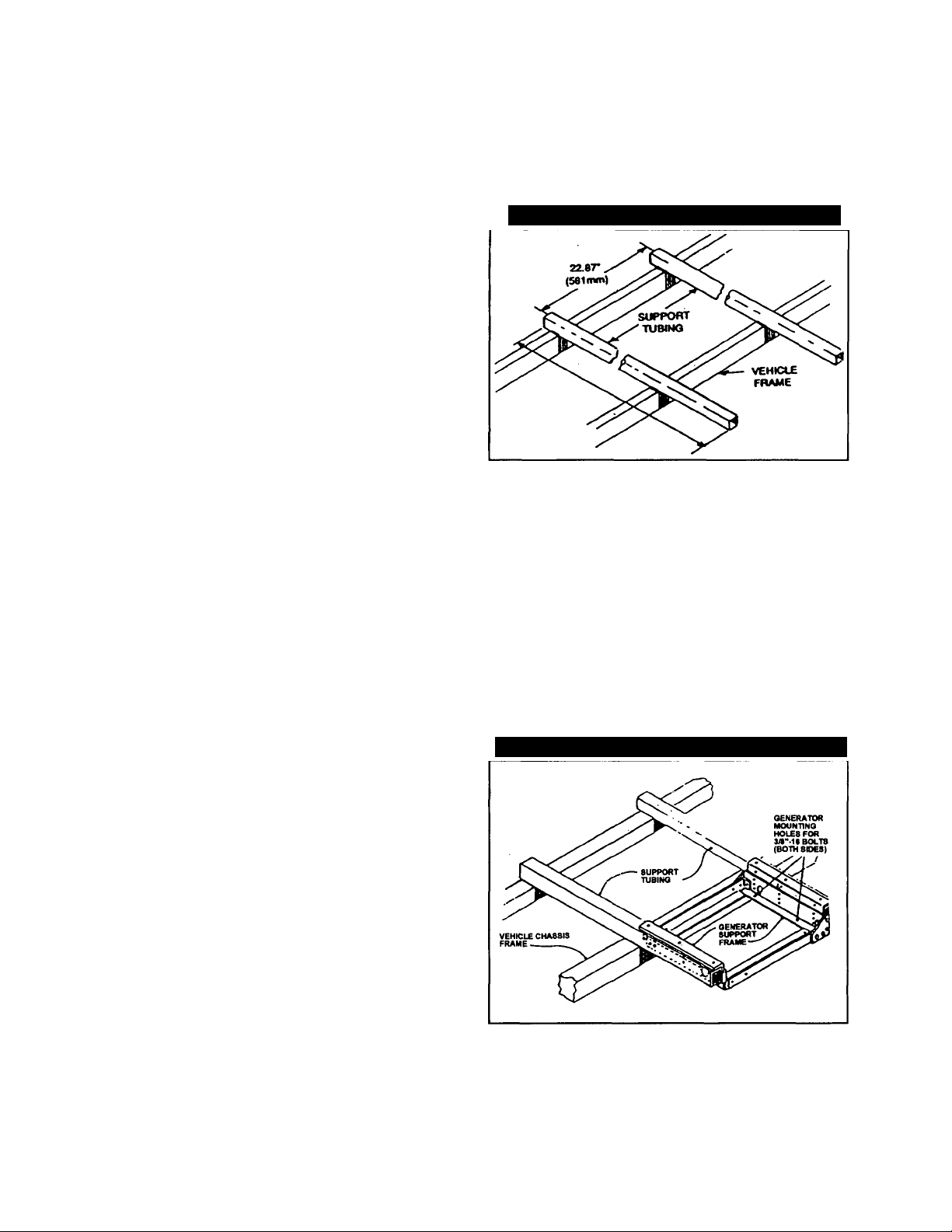
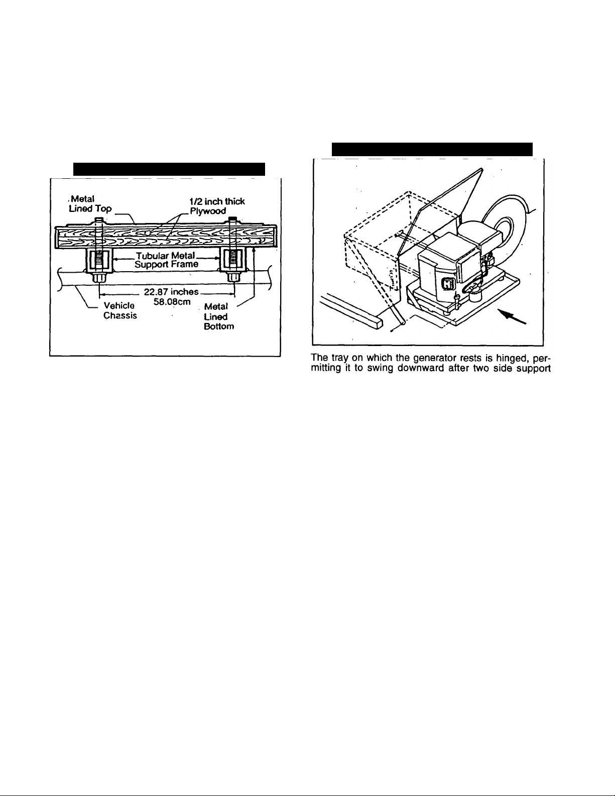
GENERATOR SUPPORT
The generator must be securely attached to a metal
framework that has been made part of the vehicle
frame structure by bolting or welding. The metal
framework on which the generator will rest and which
will restrain the generator set should consist of at
least two horizontal beams. These beams should con
sist of (a) 1-1/2 inch square, 11 gauge steel tubing
OR (b) 1-1/2 inch, 11 gauge angle iron. A typical sup
porting frame with horizontal support tubing, is shown
in Figure 3.
The generator can be installed so that it sits on top of
the horizontal support tubing, if the vehicle design
permits. Another method is to suspend the generator
below the horizontal support tubing by means of suit
able, structurally sound metal framework. The follow
ing general rules apply:
• Vehicle construction MUST be capable of supporting the
weight of the generator.
• Whether the generator is mounted above the horizontai
support tubing or suspended below the tubing, the sup
porting frame used must be structurally sound.
If the generator cannot be bolted directly to the support
ing frame or support tubing, consider using additional
tubing, angle brackets or other supports to give the sup
porting frame sufficient strength.
Figure 3 — Typical Horizontal Support Frame
SUSPENDED MOUNTING
If you are going to suspend the generator below the
horizontal support tubing, the suspension method you
use with the vehicle frame members must have the
following: (a) be able to support the weight of the gen
erator; and (b) provide sufficient restraint for the gen
erator. One typical suspended mounting system is
shown in Figure 4. The location of a suspended
mounting system must be carefully planned, keeping
the following general rules in mind:
• Protect the generator against road splash and debris.
Baffles or splash guards may be required to protect cer
tain areas of the generator. To make sure the generator is
adequately protected, road test the installation through
mud, water and slush.
Figure 4 — Typical Suspended Mounting System
• The installer must make certain the selected location will
permit adequate cooling and ventilating air flow to be
supplied.
— 5 —
Page 8
GENERATOR RESTRAINT
Use four 3/8"-16 hardened steel bolts (Grade 5) to
fasten the generator to the supporting frame or the
support tubing. These bolts must pass through (a) the
generator mounting base, (b) the compartment floor,
if a compartment is used, and (c) the supporting
framework (Figure 5). All bolts must be long enough
so that when tight, at least 3 threads are visible past
the retaining lock nuts. Refer to “COMPARTMENT’
section for location of generator mounting holes.
Figure 5 — Generator Restraint (typical)
SWING MOUNT GENERATOR TRAY
If you use a suspended mounting system, the installer
may wish to consider using the Generac Model 9164
Swing Mount Generator Tray, The Model 9164 tray
allows you to swing the generator downward and
away from the vehicle frame. This makes it simple to
remove the unit and have easy access to parts
(Figure 6).'
Figure 6 — Generator on Model 9164 Tray
rails and a center support rail are unbolted.
Instructions for tray installation are included with the
tray mounting kit.
— 6 —
Page 9
GENERATOR COMPARTMENTS
The generator set may or may not be installed inside
a compartment that is constructed specifically for
housing a generator. This section applies to generator
compartments when they are installed. The following
general rules apply to compartments:
• The generator compartment should be either
constructed of, or lined with, 26 gauge galvanized
steel.
IMPORTANT: ALUMINUM IS NOT AN ACCEPT
ABLE ALTERNATIVE TO GALVANIZED STEEL,
DUE TO ALUMINUM'S LOW MELTING POINT.
• If the compartment is lined with galvanized steel,
it may be constructed of any material. Generac
recommends that the compartment be construct
ed of 1/2-inch thick plywood, with the floor made
of a double thickness of plywood for added
strength.
• All seams, splices and joints of the compartment
walls (unless vapor tight by design) should be
caulked.
IMPORTANT: CAULKING MUST BE DONE SO
THAT THE CAULKING MATERIAL WILL STAY IN
PLACE PERMANENTLY. PRESSING SUCH MATE
RIALS AS PUTTY TAPE ONTO JOINTS AND
SEAMS WILL NOT MEET THAT REQUIREMENT. A
HIGH QUALITY SILICONE RUBBER SEALANT IS
RECOMMENDED.
• Holes and openings through the compartment
walls for passage of electrical conduit, conduc
tors, etc, into vehicle living area must be sealed
vapor-tight with silicone rubber base sealant.
• If you use flexible metal conduit, seal the conduit
at the end where it terminates inside the junction
box. Flexible metal conduit is NOT vapor tight
along its entire length.
• Seams and joints of the galvanized steel
(whether used as a liner or the compartment
itself) must be lapped and mechanically secured.
Such seams may be manufactured, welded, bolt
ed, riveted, or screwed. Manufactured lock
seams are shown in Figure 7.
COMPARTMENT SIZE
Plan the compartment size carefully. Provide a mini
mum of at least 1 inch of clearance between the gen
erator and compartment walls and 1-1/2 inch of clear
ance between the generator and the ceiling AFTER
you have lined the compartment with metal, and
AFTER you have installed sound insulation (Figure
8).
NOTE: Refer to the “Dimensions and Features” draw
ing in the back of this manual.
Figure 8 — Provide Clearance Around Generato
plywood
COMPARTMENT,
" INSULATION MSTAL LINING
1 INCH (2.S4CM)
MINIMUM CLEARANCE
ON ALL SIDES
------
000*9
'
P
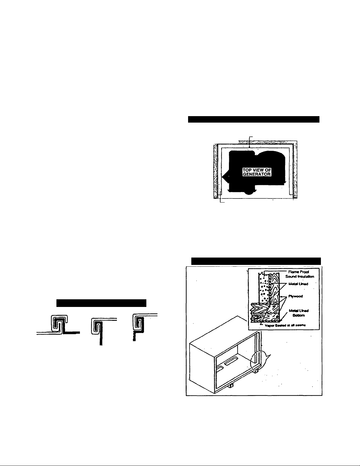
COMPARTMENT CONSTRUaiON
The generator compartment should be constructed of 1/2
inch thick plywood. Make the compartment floor a double
thickness of 1/2 inch plywood with the grain of the wood
at cross section for added strength (Figure 9).
Figure 9 — Typical Compartment Construction
Figure 7 — Types of Lock Seams
Fold Locked
Standing
Acme Lock
Offset
Double Lock
Double Seam
Gordon Seam Lock Seam
Line the entire compartment interior with 26 gauge galva
nized steel as described above.
— 7-
Page 10
• Line the exterior (underside) of the compartment floor
with 26 gauge galvanized steel.
• Vapor seal all compartment seams and joints, to prevent
poisonous, flammable or explosive vapors from entering
the vehiclef interior.
NOTE: Silicone rubber base sealant is an acceptable
caulking material. Pressing putty tape onto compart
ment joints and seams is NOT acceptable.
• After the compartment has been metal lined and vapor
sealed, line the compartment interior walls and ceiling
with an approved, non-flammable sound insulating mater
ial. See “Sound Insulating Materials.”
DANGER: DO NOT INSTALL SOUND INSULATION
OR ANY ABSORBENT MATERIAL ON THE COM
A
PARTMENT FLOOR INTERIOR. SUCH MATERIALS
WILL BECOME SOAKED WITH COMBUSTIBLE OR
EXPLOSIVE VAPORS AND LIQUIDS AND WILL
BECOME A FIRE HAZARD.
• Openings in compartment walls for passage of electrical
conduit, conductors, hoses, cables, etc., must be made
vapor tight with suitable caulking material.
• Flexible conduit must be sealed internally at the end
where it terminates inside a compartment's electrical
junction box.
NOTE: The preceding is required because flexible
conduit, due to its unique construction, is not vaportight along its entire length.
Using a combination of sound insulating materials can
often reduce noise more effectively than a single
material. For example, a sheet of lead or visco-elastic
material, along with a layer of other acoustical materi
al, is more effective than when a single material is
used.
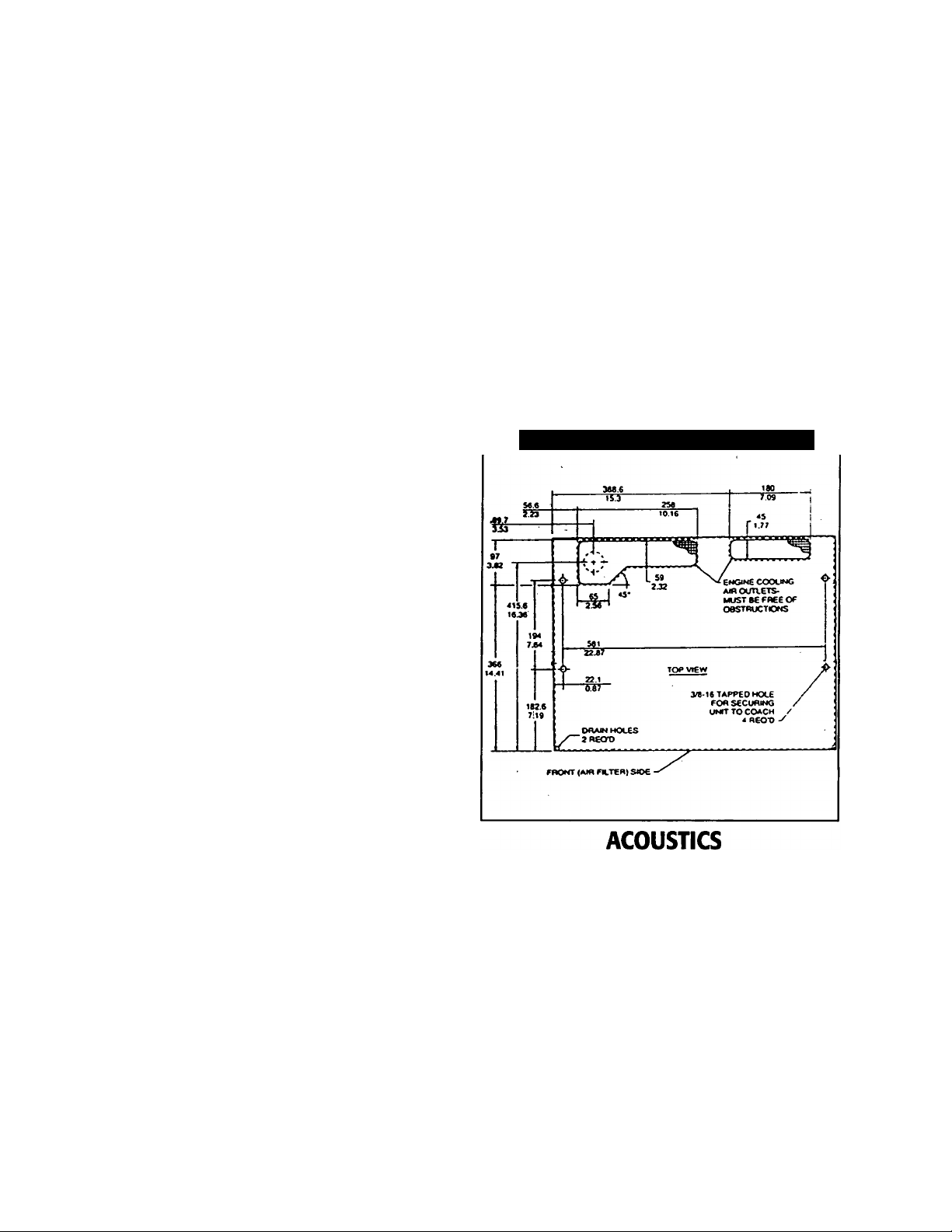
COMPARTMENT FLOOR CUTOUTS
You nriust provide openings in the generator compart
ment for the following items (Figure 10):
• Engine exhaust and cooling air outlets
• Generator cooling air inlet
• Four holes for passage of generator mounting bolts. See
“Generator Restrainf on Page 6.
DANGER: FUEL UNES AND EXHAUST PIPING
MUST NOT PENETRATE INTO VEHICLE LIVING
AREA.
Figure 10 — Compartment Floor Cutout
DANGER: DO NOT INSTALL ANY FLAMMABLE
MATERIAL DIRECTLY ABOVE OR AROUND THE
A
COMPARTMENT. HEAT, TRANSFERRED THROUGH
THE COMPARTMENT STRUCTURE, MAY BE SUF
FICIENT TO IGNITE, CHAR OR DISCOLOR SEAT
CUSHIONS, FIBERBOARD AND OTHER FLAMMA
BLE MATERIALS. YOU MAY NEED TO USE
APPROVED NON-FLAMMABLE INSULATING
MATERIALS IN HIGH TEMPERATURE AREAS.
SOUND INSULATING MATERIALS
Once installers have determined that compartments
are properly constructed and metal lined, they can
add acoustical material. This may include additional
sealant or insulating material, to reflect noise away
from the vehicle interior.
Sound insulating materials should be of a non-flam
mable type. One excellent insulating material is a 1
inch thick fiberglass having a 2-pound density. When
fiberglass is used, its coated side should face toward
the compartment interior.
If excessive noise levels should become a problem,
the installer may wish to consider the following:
• Using special sound insulating materials.
• Construction of a special noise abatement compartment.
IMPORTANT: ANY METHOD USED TO REDUCE
NOISE MUST NOT ADVERSELY AFFECT THE
FLOW OF COOLING AND VENTILATING AIR INTO
OR OUT OF THE COMPARTMENT.
Page 11

In addition to the effective use of sound insulatingmaterials, construction of a special noise abatement
compartment might be considered to reduce noise
levels. Such a compartment might be constructed as
follows (Figure 11):
DANGER; DO NOT INSTALL ANY INSULATION OR
OTHER ABSORBENT MATERIALS ON THE INTERI
OR OR UNDERSIDE OF THE COMPARTMENT
FLOOR.
Figure 11 — Typical Noise Abatement
Compartment
EXTERIOR
PLYWOOD
5/8” THICK
SOUND
INSULATION
METAL LINER
FIBERGLASS
INSULATION
PLYWOOD
5/8" THICK
Use 5/8-inch thick or 3/4-inch thick plywood in the com
partment.
Construct the compartment floor of a double thickness of
5/8-inch or 3/4-inch plywood.
Line the compartment interior walls and floor, as well as
the underside of the floor, with 26-gauge galvanized
steel.
Vapor seal all compartment seams and joints.
Over the galvanized steel lining, install a selected combi
nation of acoustical materials as mentioned in “Sound
Insulating Materials."
Seal all compartment door edges to prevent noise leak
age around the door perimeter.
Line the compartment door interior (except for air open
ings) with suitable, fire proof sound insulation (such as 1 inch thick fiberglass with a 2-pound density) See Figue
12.
Figure 12 — Typical Compartment
Door Construction
A TIMES B MUST EQUAL_AT LEAST
100 IN.'OF FREE AIR OPENING
— 9 —
Page 12

COOLING AND VENTILATING AIR
It is absolutely essential that an adequate flow of air
for cooling, ventilating and engine combustion be sup
plied to the generator set. Without sufficient air flow,
the engine-generator quickly overheats. Such over
heating can cause serious operating difficulties and
may also cause fire and personal injury. The installer
must make sure that sufficient air is available to the
generator for cooling, ventilating and combustion. The
installer must also provide for a path for exhausting
the cooling air to the exterior of a compartment, if so
equipped.
DANGER: NEVER USE DISCHARGED
COOLING AIR FOR HEATING OR PERMIT
SUCH AIR TO ENTER THE VEHICLE INTE
RIOR. THIS AIR CONTAINS DEADLY CAR
BON MONOXIDE GAS AND OTHER POISO
NOUS, FLAMMABLE OR EXPLOSIVE
GASES.
GENERATOR AIR FLOW
Engine operation drives cooling fans for the 2-stage
cooling air system. A pressure fan draws cooling air
into the top of generator and into the side of the con
trol panel (Figure 13). This air flow cools the enginegenerator and electronic .components. The second
part of cooling system, a suction fan, draws air that is
heated from a hot engine into a collector pan at the
base of the unit. This heated air (although cooler than
exhaust muffler) is directed across the muffler to cool
it. The heated air flow is then deflected out the bottom
toward the ground.
Figure 13 — Air Flow Through Engine-Generator
For conventional compartment mounted units, the air
inlet is generally provided in the compartment door.
IMPORTANT: IF YOU PLAN TO INSTALL THE GEN
ERATOR IN A COMPARTMENT, BE SURE TO
LEAVE AT LEAST ONE AND A HALF (1-1/2") INCH
ES OF CLEARANCE BETWEEN THE GENERATOR
AND COMPARTMENT CEILING. INCLUDE 26
GAUGE GALVANIZED STEEL LINING AND SOUND
INSULATION WHEN YOU MEASURE FOR THIS 1-
1/2 INCH CLEARANCE. ALLOW 1” ON ALL SIDE
WALLS.
Figure 14 — Air Inlet in Compartment Door
MINIMUM FREE INLET
AREA =100 INCHES^
When the unit is installed on a suspended mounting
system, one of several different methods of supplying
air flow may be used as follows:
• Provide a door in the vehicle skirt having an air
inlet opening (Figure 15).
COOLING AIR INLET OPENING
Minumum size of the air inlet opening, whether the
generator is housed in a conventional compartment or
not, is at least 100 square inches. This rule applies
whether inlet air is brought in through an opening in
the compartment door (Figure 14) or other means.
NOTE: Screening, louvers, or expanded metal that
cover air openings restrict air flow that you must com
pensate for by making the actual air opening propor
tionately larger. See “Compensating for Restnctions."
— 10 —
Figure 15 — Suspended Mount: Inlet Door
MINIMUM FREE I
INLET AREA
100 INCHES’ Em?
f
• IL.
Using ductwork (Figure 16 on Page 11). The
instailer must be sure air is available to the top of
the generator since air inlets are located at the
top.
By providing an opening in the vehicle skirt and
space above the generator for cooling air flow
(Figure 17 on Page 11). Recommended clear
ance above the top of the generator is at least 1 -
1/2 inches.
L
Page 13

Figure 16 — Air Inlet Using Ductwork
Figure 17 — Air Inlet in Vehicle Skirt
COMPENSATING FOR
RESTRiaiONS
Such materials as screening, louvers, or expanded
metal can restrict the free flow of air. Compensate for
this restriction by making the actual air opening pro
portionately larger.
Some materials may offer only a 60 percent “free air
inlet area.” Other more efficient materials may provide
up to a 90 percent free air inlet area. The percentage
of free air inlet opening is usually available from the
material supplier or manufacturer.
TO DETERMINE THE ACTUAL AIR INLET OPEN
ING SIZE REQUIRED, DIVIDE 100 SQUARE INCH
ES BY THE PERCENTAGE OF FREE AIR INLET
AREA FOR THE MATERIAL YOU WILL USE.
For example: If you plan to use screening with an
80% free air inlet area, divide 100 by 0.8, which
results in 125 square inches. Minimum actual size of
air inlet opening in this casé is 125 square inches. An
opening that measures 8 inches wide by 16 inches
long provides the required air flow (8 x 16 = 128
square inches).
RECOMMENDED CLEARANCE • 1-1/2 IN. (38.1 MM) ^
MINIMUM CLEARANCE - 1 IN. (25.4MM)
VEHICLE FLOOR
.-L
ENGINE
SIDE
VIEW
J
VEHICLE
.SKIRT
TESTING THE INSTALLATION
Generac recommends testing the installation to be
sure adequate cooling air flow is available to the unit
before placing the unit into service. If the unit shows
signs of overheating, you will need to enlarge the air
openings. Never place a unit into service until
absolutely certain that cooling and ventilation is ade
quate.
IMPORTANT: YOU MUST TEST THE INSTALLA
TION ESPECIALLY IF YOU BRING IN AIR FROM
BELOW THE GENERATOR SET.
11 —
Page 14

GASOLINE FUEL SYSTEM
Installing a gasoline fuel system (Figure 18) for recre
ational vetiicle generator sets must comply with
applicable codes, standards and regulations. The
entire fuel system must be completely free of leaks.
There must be no possibility of gasoline vapors enter
ing the vehicle interior.
Figure 18 — Generator Fuel System
DANGER: GASOLINE IS HIGHLY FLAMMABLE
AND ITS VAPORS ARE EXPLOSIVE. COMPLY
A
WITH ALL CODES, STANDARDS AND REGULA
TIONS PERTAINING TO GASOLINE FUEL SYS
TEMS USED IN INDUSTRIAL MOBILE GENERA
TORS. PROPERLY INSTALL AND MAINTAIN THE
FUEL SYSTEM AND KEEP IT ENTIRELY FREE OF
LEAKS. GASOUNE VAPORS MUST NOT ENTER
THE VEHICLE INTERIOR.
Factory installed generator fuel system components
include (a) fuel filter, (b) 12-volt DC electric pump, (c)
engine carburetor, and (d) interconnecting lines and
fittings. Connect a fuel supply line to the fuel filter inlet.
Use a flexible length of approved fuel hose between
the fuel filter inlet connection and rigid fuel lines.
FUEL TANK
Either the generator must share the vehicle engine's
fuel tank, or you must install a separate fuel tank for
the generator set. All fuel tanks installed on the vehi
cle must be constructed, installed, restrained so it
complies with applicable codes, standards and regu
lations.
If the generator is to share the vehicle engine's tank,
separate fuel pickup tubes are required for the engine
and the generator. Generac recommends that you
make the fuel pickup tube about 2 to 3 inches shorter
than the vehicle engine's pickup tube. This prevents
the generator from depleting the entire fuel supply
during prolonged generator operating periods.
CAUTION: Do NOT tee the generator fuel supply
line into the vehicle engine fuel supply line. If this
is done, the generator will be starved of fuel when
both engines are operating at the same time. Also,
while the vehicle engine is not running, generator
operation may drain the vehicle engine supply line,
making it difficult to start the vehicle engine.
GENERATOR FUEL SUPPLY LINE
RIGID FUEL LINES
Those lines used to supply fuel from a tank to the
generator must comply with ac applicable codes, standards and regulations.' The following generator rules
apply to rigid fuel lines:
• Rigid lines should be of annealed, seamless, drawn alu
minum or steel.
• Lines and fittings must comply with SAE J512F,
“Standard Automotive Fittings”, or with ANSI B126.26
(latest edition).
• Route the fuel line so that at least 2 inches of clearance
is maintained between the line and any exhaust system
parts.
• Do not attach electrical wiring to fuel lines. Route the
wiring so it cannot come into contact with any fuel line.
• Route fuel lines so if they leak, fuel does not drip onto
any electrical or exhaust system parts.
• Use non-ferrous metal straps without sharp edges to
secure fuel lines.
I fu
■ FLEXIBLE FUEL LINE
Use an approved flexible length of fuel hose between
the generator fuel inlet connection and rigid fuel lines.
This prevents breaking of the line caused by vibration,
shifting, settling or movement. The following rules
apply:
• The flexible hose must comply with SAE J30B, “Standard
for Fuel and Oil Hose”. It must be approved for use with
gasoline.
• The hose should be at least 6 inches longer than is need
ed to prevent the hose from rupturing if the generator
shifts or settles.
with
iliowir
__________________
12 —
Page 15

PROPANE GAS FUEL SYSTEM
DANGER: LP (PROPANE) GAS IS HIGHLY EXPLO
SIVE. THE GAS IS HEAVIER THAN AIR AND
TENDS TO SEHLE IN LOW AREAS, WHERE EVEN
THE SLIGHTEST SPARK CAN IGNITE IT AND
CAUSE AND EXPLOSION. ONLY COMPETENT,
QUALIFIED PERSONS SHOULD BE ALLOWED TO
INSTALL, TEST, ADJUST OR SERVICE AN LP GAS
FUEL SYSTEM. INSTALL THE OPTIONAL FUEL
SYSTEM IN COMPLIANCE WITH APPLICABLE
CODES, STANDARDS AND REGULATIONS. AFTER
THE INSTALLATION, DO NOTHING THAT MIGHT
RENDER THE SYSTEM IN NON-COMPLIANCE
WITH APPLICABLE CODES AND STANDARDS.
The LP powered range of Gensets are fitted with nonadjustable factory set system. These systems are
tamper-proof to meet 1997 California Air Resources
Board for Engine Emmissions.
PARTS NOT INCLUDED IN FUEL SYSTEM
The propane fuel system does NOT include such
items as (a) gas tank, (b) gas piping, (c) fittings, (d)
valves, and (e) primary regulator, used to store the
gaseous fuel and deliver it to the gaseous fuel sole
noid (Figure 19).
DANGER: USE ONLY APPROVED COMPONENTS
IN THE GAS SUPPLY SYSTEM. ALL COMPONENTS
MUST BE PROPERLY INSTALLED IN ACCOR
DANCE WITH APPLICABLE CODES. IMPROPER
INSTALLATION OR USE OF UNAUTHORIZED COM
PONENTS MAY RESULT IN FIRE OR AN EXPLO
SION. FOLLOW APPROVED METHODS TO TEST
THE SYSTEM FOR LEAKS. NO LEAKAGE IS PERMIHED. DO NOT ALLOW FUEL VAPORS TO
ENTER THE VEHICLE INTERIOR.
SOME IMPORTANT CONSIDERATIONS
When installing an LP gas system, consider seriously
the following items:
• All fittings, lines, hoses and clamps must be tight and free
of leaks. Apply a pipe sealant to threads when assem
bling threaded connections. This reduces the possibility
of leakage.
• Test the entire fuel system for leaks, using approved test
methods.
Figure 19 — Typical Propane Gas Fuel System
Page 16

• Optimum gas pressure at the inlet to the gaseous fuel
solenoid valve and secondary regulator is 11 inches
water column.
• The instaljer’s fuel supply connection point is at the
gaseous fuel solenoid valve. This is a 3/4 inch (female)
connection. Provide a suitable 3/4 inch NPT (male) con
nector to attach to the fuel supply line.
• Use a length of approved flexible fuel hose between
gaseous fuel solenoid valve and rigid gas piping. The
flexible line should be at least six (6) inches longer than
necessary.
VAPOR WITHDRAWAL
Liquid propane (LP) gas is stored in pressure tanks
as a liquid. The gas systems used with these genera
tors were designed only for “vapor withdrawal” type
systems. Vapor withdrawal systems use the gas
vapors that form above the liquid fuel in the tank. Do
NOT attempt to use the generator with any “liquid
withdrawal” type system.
PRIMARY REGULATOR
Gas pressure delivered to the solenoid valve must be
properly regulated by means of a primary gas regula
tor. Mount the primary regulator at the gas tank outlet
or in the supply line from the gas tank. The following
rules apply:
• For best results, the primary regulator supplies gaseous
fuel to the secondary regulator at 11 inches water col
umn. Do NOT exceed 14 inches water column.
• The installer must be sure the primary regulator is rated
at sufficient gas flow to operate the generator plus all
other gas appliances in the circiut.
NOTE: Recommended MINIMUM gas flow rate for all
air-cooled NP or Q series generators is 67 cubic feet
per hour.
IMPORTANT: IF AN EXISTING PRIMARY GAS
REGULATOR DOES NOT HAVE A SUFFICIENT
FLOW CAPACITY FOR THE GENERATOR AND
OTHER GAS APPLIANCES IN THE CIRCUIT, (a)
INSTALL A PRIMARY REGULATOR WITH ADE
QUATE FLOW RATE, OR (b) INSTALL A SEPA
RATE REGULATOR ONLY AND RATED AT LEAST
67 CUBIC FEET PER HOUR. THE INLET SIDE OF
ANY PRIMARY REGULATOR THAT SUPPLIES THE
GENERATOR MUST CONNECT DIRECTLY TO
GAS TANK PRESSURE. DO NOT TEE THE GEN
ERATOR LINE INTO A GAS CIRCUIT FEEDING
OTHER AREAS.
GASEOUS CARBURETION
LP gas vapors should be supplied to the secondary
regulator inlet at about 11 inches water column (posi
tive pressure). The engine pistons draw air in during
the intake stroke (Figure 20). This air passes through
a carburetor venturi which creates a low pressure that
is proportional to the quantity of air being pumped.
The low pressure from the carburetor venturi acts on
the regulator diaphragm, to pull the diaphragm toward
the source of low pressure. A lever attached to the
diaphraghn opens a valve to permit gas glow through
the carburetor.
The greater the air flow through the carburetor ven
turi, the lower the presure at the venturi throat. The
lower the pressure at the venturi throat, the greater
the diaphragm movement and the greater the move
ment of the regulator valve. The more the regulator
valve opens, the greater the gas flow that is propor
tional to air flow through the generator.
AIR
Figure 20 — Propane Gas Carburetion Diagram
GAS AT
AREA
— 14 —
Page 17

The following facts about the secondary regulator
must be emphasized;
• The regulator must be sensitive to venturi throat pressure
changes throughout the operating range.
• The regulator must be properly adjusted so it will stop the
flow of gas when the engine is not running (no air flow
through the carburetor).
• The slightest air flow (and vacuum in the venturi throat
should move the regulator valve off its seat and permit
gas to flow.
LEAKAGE TESTS
Do not place the generator into service untii you have
properly tested the gas system for leaks. To test the
system, you need a separate source of 12 volts DC to
open the gaseous fuel solenoid valve.
The leak test must comply fully with NFPA, Paragraph
318. All connections, hoses, valves regulators, fit
tings, and other fuel system parts must be tested
under gas or air pressure of not less than 90 psi
(620kPa), while using soap and water or equivalent
solution to check for leaks. Other approved methods
of testing for leaks may be used, if appropriate. DO
NOT USE ANY FLAME TO TEST FOR LEAKS.
FUEL SUPPLY LINES
• Propane gas lines must be accessible, but protected
against possible damage.
• Do NOT connect electrical wiring to any propane gas fuel
line or run wiring alonside the lines.
• Route gas lines away from hot engine exhausts.
• Retain gas lines with metal clamps that do not have
sharp edges.
• Install an approved length of flexible hose between the
gaseous fuel solenoid valve and rigid fuel supply lines.
The flexible line must be non-metallic, non-organic and
non-conductive. It must be approved for use with LP gas.
EXCESS FLOW VALVE
Propane gas tanks should have an excess flow valve,
according to NFPA 501C, Paragraph 3-4.4. This valve
and the gas lines must be carefully sized so the valve
will close when a fuel line is severed or broken.
Consult the Natural-LP Gas Association for informa
tion and limitations of excess flow valves.
Manual shutoff valves on the supply tank and else
where in the system must be fully open when operat
ing the generator. The excess flow valve functions
properly only if all valves are fully open.
DANGER; GASEOUS FUEL LINES BETWEEN THE
TANK AND THE SECONDARY REGULATOR ARE
A
UNDER A POSITIVE PRESSURE (ABOUT 11 INCH
ES WATER COLUMN). GAS PRESSURE AT THE
OUTLET SIDE OF THE SECONDARY REGULATOR,
HOWEVER, IS A NEGATIVE PRESSURE AND CAN
DRAW FLAME INSIDE A LINE OR FIHING AND
CAUSE AN EXPLOSION.
— 15 —
Page 18

EXHAUST SYSTEM
The generator exhaust system must be safely and
properly installed. Only approved mufflers and other
exhaust system parts must be used. A properly
installed exhaust system must be vapor tight, quiet
and completely safe.
CAUTION: Never tee the generator engine exhaust
pipe into the vehicle engine exhaust piping. This
causes excessive back pressure on the generator
engine. Also, water from one engine can damage
the other engine.
DANGER: THE GENERATOR ENGINE GIVES OFF
DEADLY CARBON MONOXIDE GAS THROUGH ITS
EXHAUST SYSTEM. THIS DANGEROUS GAS, IF
BREATHED IN SUFRCIENT CONCENTRATIONS, CAN
CAUSE UNCONSCIOUSNESS OR EVEN DEATH. SYMP
TOMS OF CARBON MONOXIDE POISONING ARE (a)
INABILITY TO THINK COHERENTLY, (b) VOMITING, (c)
TWITCHING MUSCLES, (d) THROBBING IN TEMPLES,
(e) DIZZINESS, (f) HEADACHE, (g) WEAKNESS AND
SLEEPINESS. IF ANY OF THESE SYMPTOMS ARE
EXPERIENCED, MOVE INTO FRESH AIR IMMEDIATELY.
IF SYMPTOMS PERSIST, GET MEDICAL ATTENRON.
DO NOT OPERATE THE GENERATOR UNTIL ITS
EXHAUST SYSTEM HAS BEEN INSPECTED AND
REPAIRED.
MUFFLERS AND SPARK ARRESTORS
If the generator is not equipped with a spark arrestor
exhaust muffler and is to be used on any forest cov
ered, brush covered or grass covered unimproved
land, you may have to install a spark arrestor. The
spark arrestor must be maintained in effective work
ing order by the vehicle owner/operator.
For assistance in ordering, installing and maintaining
spark arrestor exhaust mufflers, contact your nearest
authorized service facility.
Exhaust mufflers supplied by Generac are spark
arrestor types. Generac exhaust mufflers for NP and
Q series generators do not have a spark arrestor
screen, but are of the more efficient “toroid” or “swirl”
type. To remove carbon and combustion deposits
from such mufflers, remove the PLUG from muffler
and run engine for about 15 minutes. Shut down, let
the muffler cool and install the plug.
WARNING: BE SURE TO RE-INSTALL THE PLUG
FROM THE MUFFLER TIGHTLY. ENGINE VIBRA
A
TION COULD CAUSE A LOOSE PLUG TO FALL OUT.
WITHOUT THE PLUG IN PLACE, HOT ENGINE
EXHAUST IS DIRECTED OUT THE OPENING. THIS
HOT EXHAUST, DEPENDING ON THE INSTALLA
TION, COULD BE DIRECTED TO AREAS NOT ABLE
TO WITHSTAND THE EXTREME HEAT SUCH AS
WOODEN FLOOR BOARDS OR OTHER FLAMMA
BLE MATERIALS. THIS COULD RESULT IN A FIRE.
TYPE OF EXHAUST SYSTEM
Two types of exhaust systems for “NP” and “Q” series
generators are available from Generac. They include
these;
• “Out-the-bottom” exhaust system, Model 9742 (Figure
21). '
• “Out-the-side” exhaust system, Model 9743 (Figure 22 on
Page 17).
NOTE: No matter what type of exhaust kit best fits
your recreational vehicle, the mounting base has
openings for either “bottom-ouf or “side-out exhaust
systems. Use the cover plate provided with the gen
erator to cover the opening you do NOT use.
Figure 21 — Model 9742 Exhaust System
ITEM PART NO. DESCRIPTION QTY
52108 Rinffler r
2 46591 Hanger 1
28238
3
28237 Clamp, Saddle
4
5 22129
22259 5/16”Hex Nut
6
7
75238 Pipe
75411 Elbow 1
8
9 77643 Gasket 2
77642 Adaptor, Bottom Out 1
10
11 68527
U-Bolt 3
Lock\Vasher
M6-1.0 X 20mm Screw 2
3
6
6
1
16-
Page 19

EXHAUST SYSTEM SAFETY
• Maintain a clearance of at least 3 inches (76mm)
between exhaust system parts and any combustible
material (such as wood, felt, cotton, organic fibers or
other like material). If you cannot maintain the 3-inch
clearance, locate, insulate or shield the exhaust part(s)
so that the temperature of any combustible material is not
raised more than 117°F (65“C) above the ambient air
temperature.
• Terminate the exhaust tailpipe such that exhaust gases
will not be drawn back into the generator compartment
and recirculated.
• If there is any possibility of the tailpipe or muffler being
damaged, protect these damage prone areas by means
of a protective device (such as a “skid baf).
• Install the generator exhaust system according to safe
automotive practices.
• Use enough exhaust system hangers to prevent
any part of the system from being dislocated.
Figure 22 — Model 9743 Exhaust Kit
Use exhaust system parts recommended by
Generac. Using unapproved exhaust mufflers
and exhaust system parts is the responsibility of
the person(s) installing such unauthorized parts.
Do not terminate the exhaust system under the
vehicle.
. Do not terminate the exhaust system under any
opening, window or vent which can be opened or
is not permanently sealed from the vehicle interi
or.
Exhaust piping must be large enough to prevent
excessive back pressure on the generator
engine.
Never tee the generator engine exhaust pipe into
the vehicle engine exhaust piping. This causes
excessive back pressure on the generator
engine. Also, water from one engine can damage
the other engine.
Plan exhaust system installation carefully.
Comply with all applicable codes, standards and
regulations.
ITEM
1 .22129
2
3
4 81107
5
6
7 76508
PART NO.
42907
45771
92675A
94670
DESCRIPTION
5/16”-M8 Lockwasher
M8-1.25 X 16 Screw
M8-1.25 Hex Nut
Exhaust Pipe Extension
Exhaust Muffler
1.120 Exhaust Clamp
. Muffler Bracket
QTY. ITEM
4
4
2 10
1 11 92676
1 12
2
1
— 17 —
8
9
13
PART NO. DESCRIPTION QTY.
77643 Gasket
90863 Adaptor 1
79246 M6-1.0 X 20mm Capscrew 2
95277
56893
Muffler Adaptor 1
Outlet Adaptor Gasket
#10-24 X 1/2 Crimptite
2
1
3
Page 20

ELECTRICAL CONNECTIONS
The following general rules apply to electrical connec
tions in a recreational vehicle:
• Qualified electricians who are familiar with applicable
codes, standards and regulations should install electrical
wiring.
• The wiring should comply with codes, standards and reg
ulations. The National Electric Code (NFPA 70), as well
as state and local codes, apply.
• Switches and circuit breakers should be of a type
approved for use in recreational vehicles and must be
mounted and installed to prevent damage from road
shock.
• Wiring must be of adequate size, with approved insulative
qualities, and properly supported.
Conduit and wire openings into generator compartment
(if used) must be vapor-sealed, to prevent entry of flam
mable, explosive or poisonous gases into the vehicle.
ELEamCAL JUNQION BOX
Install an approved, square electrical junction box that
has a blank cover on the interior or exterior wall of the
area you plan to install the generator (NOT on the
generator). Route the generator's AC output leads
into this junction box through approved flexible con
duit, and into this junction box. This is the point of first
termination for generator AC output leads.
• From the junction box route power supply wires through
approved conduit to either (a) double-pole, double-throw
transfer switch, or (b) approved isolation receptacle.
Connecting to a transfer switch or isolation receptacle
must prevent vehicle electrical circuits from being con
nected to two different power supplies at the same time
(such as generator and dockside power).
• Conductors must be rated 221°F (105“C) or must be of a
larger conductor size.
GENERATOR AC CONNEaiONS
Generator AC output leads T1 (red) and T2 (white)
and T3 (black) come out of the generator as shown in
Figure 23. Leads T1 (red) and T3 (black) are “hot,”
while T2 (white) is the grounded “neutral”. There is
also a green lead that connects to ground in the junc
tion box of the recreational vehicle.
Figure 23 — Generator AC Output Leads
WIRING
• Wiring should be of stranded copper to reduce chance
that vibration may cause breakage.
• Wire gauge size of wires should be large enough to han
dle at least 115% of the installed generator's rated maxi
mum current.
• If neutral conductors are used, they must be the same
size as other leg wires.
• Route power supply conductors from generator AC output
leads T1 (red) and T2 (white), T3 (black) and the green
ground wire through approved flexible conduit to the elec
trical junction box on the compartment wall.
If flexible metal conduit is used between the generator
and the compartment junction box, the conduit end that
terminates the compartment junction box, must be vaporsealed. Flexible metal conduit is NOT vapor tight along its
entire length.
Line T1 (red) to T2 (white) is protected against over
load by the circuit breaker (CB1). Use this line-to-neutral connection separately to operate 120 volts, 1phase, 60 Hz, AC loads requiring up to 3600 watts
(3.6 kW) of power. Line T3 (black) to T2 (white) is
also protected against overload by a circuit breaker
(CB2). Use this line-to neutral connection separately
to operate similar loads. However, be sure the total
unit load does NOT exceed the maximum rating of
the generator. The neutral line (T2, white) on all units
is a grounded neutral.
NOTE: The generator may be reconnected for dual
voltage AC output. (See “Dual Voltage Reconnection
on page 3).”
CAUTION: Do NOT connect electrical loads in
excess of any circuit breaker rating or you will
A
develop problems with circuit breaker tripping,
which causes a loss of AC output Also, do NOT
exceed the generator's rated wattage capacity. Add
the watts or amperes of all lighting, appliance, tool
and motor loads the generator will operate at one
time. This total should be less than the unit's rated
wattage/amperage capacity.
— 18 —
Page 21

CONDUIT
Route the conductors between the generator and the
junction box through approved, flexible conduit. The
following general rules apply:
• Cut wiring to the required length and allow extra wire for
junction box connections.
• Carefully prepare conduit ends, to prevent sharp edges
from cutting through wiring insulation.
• Route conduit so it does not interfere with generator
movement.
• If you use metallic conduit, vapor seal the end of the con
duit where it enters the junction box. Do this because
flexible metallic conduit is not vapor proof along its entire
length.
ISOLATING DIFFERENT POWER
SOURCES
Conductors from the junction box must terminate in a
double pole, double throw transfer switch (Figure 24).
An alternate method for isolating different power
sources is by using an isolating receptacle (Figure 25
on Page 20). Whichever method you use, you must
be certain that both power sources are NOT connect
ed at the same time.
POWER SUPPLY CORD
The power supply cord must comply with all applica
ble codes, standards and regulations. It must be large
enough to handle the full amperage to which it will be
subjected.
GROUND FAULT CIRCUIT
INTERRUPTERS
The National Electric Code (NFPA 70, 551-7) requires
that you install ground fault circuit interrupters
(GFCIs) on all external and some internal electrical
receptacles. Contact your manufacturer or dealer for
recommendations.
FLEXIBLE
CONDUIT
1—1
I JlHiPÜ
Figure 24 — Transfer Switch Isolation Method
FROM
HACR BREAKER_____
VEHICLE
WIRING
b
-1
POWER SUPPLY CORD
2ND AIR
CONOITIONEB
VEHICLE A-C
DISTRIBUTION
PANEL
MAIN BREAKER
HACR
BREAKERS
FOR AIR
CONDITIONERS
GFCI
BREAKERS
— 19 —
Page 22

Figure 25 — Installation with Isolation Receptacle
DOCKSIDE
POWER
DISTRIBUTION
PANEL
— 20 —
Page 23

DUAL VOLTAGE RECONNECTION
NOTE: Be sure to read “Reconnection for Dual
Voltage: on page 3. Installers must be aware that if
they reconnect the generator for dual voltage AC out
put, the generator is not listed per RVIA.
When reconnecting these units for dual voltage,
replace the existing circuit breakers with a single suit
ably rated circuit breaker.
RECONNEQION PROCEDURE
NOTE: Not applicable to Q-40G model.
t.Gain access to the generator panel interior by removing
the generator cover and the front panel (Figure 26).
Figure 26 — Removing Cover and Panel
3. Disconnect stator, leads 11 and 33 from the 4-tab terminal
connector (TC).
4. Disconnect stator leads 22 and 44 from the grounding
terminal (GT).
5. Disconnect one of the two 12 (white) leads from the
grounding terminal.
6. Remove the existing circuit breakers CB1 and CB2.
Install new appropriately rated circuit breaker.
7. Connect stator leads 11 and 44 to the new circuit breaker
as shown in Figure 28. Also attach leads T1 (red) and T3
(black) to the circuit breaker as shown.
8. Connect stator leads 22 and 33 to the grounding terminal
(GT) as shown (Figure 28).
9. Be sure a neutral lead is installed and routed from the
grounding terminal for connection loads.
10. Routs leads T1 (red) and T3 (black) and the grounded
neutral lead through the conduit clamp and out of the
panel.
11 .Reassemble the panel and generator cover.
Loads may now be connected as follows (Figure 28):
• T3 (black) to Neutral — 120 volts
• T1 (red) to Neutral — 120 volts
• T1 to T3 — 240 volts
2. Disconnect stator leads 11 and 33, T1 (red) and T3
(black) from the main circuit breakers CB1 and CB2
(Figure 27). Set aside leads T1 (red) and T3 (black) for
later use.
Figure 27 — Existing
Wiring Connections — 120 Volts
Figure 28 — Reconnected for Dual Voltage
— 21 —
Page 24

BATTERY INSTALLATION
RECOMMENDED BAHERY
Install a battery that meets the following require
ments:
• Battery must be a 12 volt, automotive type storage bat
tery.
• For prevailing ambient temperatures above 32°F (0°C),
use a battery rated 70 amp-hours and capable of deliver
ing 360 cold cranking amperes.
• For prevailing ambient temperatures below 32°F (0°C),
use a battery rated 95 amp-hours and capable of deliver
ing 450 cold cranking amperes.
IMPORTANT: IF THE BATTERY IS TO BE USED TO
POWER OTHER VEHICLE ACCESSORIES, AS
WELL AS START THE GENERATOR, YOU MAY
NEED A BATTERY WITH A LARGER CAPACITY.
BAHERY CABLES
Using battery cables that are too long or too small in
diameter may cause a drop in voltage which causes
starting problems. For best cold weather starting, the
voltage drop between battery terminals and the gen
erator connection point should not exceed 0.12 volts
per 100 amperes of cranking current.
Q Series generators are rated at about 100 DC
amperes of cranking current.
Select battery cables based on (a) cable length, and
(b) prevailing ambient temperatures. Generally, the
longer the cable and the colder the weather, the larg
er the cable size must be (as shown in the chart in the
next column).
CABLELENGTH
in Feet (meters) CABLE SIZE
0to10(0to3) 2*
11 to 15 (3.4 to 4.5) 0
16 to 20 (4.5 to 6) 000
* For warm weather, use No. 2 cable up to 20 feet.
BAHERY CABLE CONNEaiONS
1. Connect the battery cable from the battery post or termi
nal indicated by a POSITIVE, POS or (+) to the large lug
on the starter contactor (Figure 29).
2. Connect the battery cable from the battery post indicated
by a NEGATIVE, NEG or (-) to the frame ground connec
tion (Figure 27).
3. Connect cables so the connectors are clean and tight.
NOTE: Check to be sure the battery cable boot for
the starter cable has been installed.
BAHERY COMPARTMENT
Install the generator battery in its own, vented com
partment. Place the battery compartment away from
any source of heat, sparks or flame.
Provide ventilation openings in the battery compart
ment. The minimum size of openings should be 2
square inches at the top of the compartment. Mount
the battery on a strong, rigid supporting structure,
where leaks and spills of battery fluid will not cause
damage.
Figure 29 — Connecting Battery Cables
ATTACH NEGATIVE BATTERY CABLE
TO ONE OF THESE LUGS
— 22 —
GROUND LUG
Page 25

POST INSTALLATION TESTS
The air cooled generator set was factory tested and
adjusted to provide maximum power. You should not
be required to adjust the unit any further except under
special circumstances.
WARNING: DO NOT MAKE ANY UNNECESSARY
ADJUSTMENTS. FACTORY SETTINGS ARE COR
RECT FOR MOST APPLICATIONS. WHEN MAKING
ADJUSTMENTS, HOWEVER, BE CAREFUL TO
AVOID OVERSPEEDING THE ENGINE.
BEFORE INITIAL START UP
Before starting, complete the following:
1. Check engine crankcase oil level and, if necessary, fill to
dipstick FULL mark with the recommended oil. Do not fill
above FULL mark.
2. Check the fuel supply. Gaseous fuel lines must have
been properly purged and leak tested in accordance with
applicable fuel-gas codes. All fuel shutoff valves in the
fuel supply lines must be open.
DANGER: IF AN LP (PROPANE) GAS FUEL SYS
TEM HAS BEEN INSTALLED, IT MUST HAVE BEEN
PROPERLY TESTED FOR LEAKS BEFORE OPER
ATING THE SYSTEM IN COMPLIANCE WITH ANSI
A119.2/NFPA 501C. NO LEAKAGE IS PERMIHED.
YOU MUST BE SURE NO GASEOUS FUEL
VAPORS ENTER THE VEHICLE INTERIOR.
INITIAL START
When absolutely certain that the unit has been prop
erly installed and prepared for use, start the engine as
follows:
1. Turn off all electrical loads. Do this by setting the generator
main circuit breakers to their “OFF or “OPEN” position.
2. Refer to the Owner's Manual shipped with unit for crank
ing and starting instructions. The engine may require
more cranking for initial starting since the fuel lines have
to be primed.
3. Let the engine warm up for about five minutes to allow
internal temperatures to stabilize.
4. Carefully inspect the engine-generator for fuel, oil and
exhaust system leaks. Before proceeding to the next
step, correct any leakage immediately.
5. When engine has stabilized and warmed up, check the
no-load voltage and frequency. See “Checking No-Load
Voltage and Frequency”. Initial tests and adjustments are
done at no-load condition.
6. When all tests and adjustments at no-load are completed,
apply electrical loads and check for proper operation
under load. See “Testing Under Load”. Run the unit at
least 30 minutes with loads applied.
7. Turn off all electrical loads by setting the generator main
circuit breakers to “OFF or “OPEN.”
8. Let the unit run at no-load for a few minutes to stabilize
internal engine-generator temperatures. Then, shut down
the engine.
IMPORTANT: THE GENERATOR SET WAS THOR
OUGHLY TESTED AND ADJUSTED AT THE FAC
TORY BEFORE SHIPPING. NO ADDITIONAL
ADJUSTMENT SHOULD BE NECESSARY. ONLY
QUALIFIED SERVICE TECHNICIANS WHO HAVE
BEEN TRAINED SHOULD PERFORM ADJUST
MENTS OUTLINED IN THIS MANUAL.
CHECKING NO’LOAD VOLTAGE
AND FREQUENCY
Connect an accurate AC voltmeter and an AC fre
quency meter across the generator’s AC output leads.
This can be done at a convenient point in the circuit
(such as the transfer switch terminals or isolating
receptacle). Connect the meters across lines T1 (red)
and T2 (white); or across line T3 (black and T2
(white). Line-to-neutral readings will be taken with
unit at no-load condition.
t.With generator running, stabilized and warm, check the
AC frequency and voltage. Frequency shoud be about 62
Hz; voltage about 122-126 volts AC.
2. After taking frequency and voltage readings, determine if
any adjustment is required as follows:
• If frequency and voltage are both good, no adjust
ment IS needed.
• If frequency is high or low, adjust the engine gov
ernor to obtain 62 Hertz at no-load. Then, recheck
voltage reading.
• If frequency is good but voltage is high or low,
adjust the voltage regulator to obtain 124 volts at
62 Hz (no-load).
NOTE: If the generator has been reconnected to pro
vide a dual voltage AC output (Page 18), line-to-line
frequency and voltage readings may be used.
Frequency at no-load should be about 62 Hz; line-toline voltage should be about 244-252 volts.
TESTING UNDER LOAD
After it has been determined that no-load frequency
and voltage are correct, apply electrical loads equal to
about 75-100% of the unit s rated wattage/amperage
capacity. Check frequency with electrical load
applied. The frequency should not drop below about
58 Hz under load.
Let the unit run at least 30 minutes with load applied.
During this part of the test, check that the unit is not
running excessively hot and that adequate cooling air
flow is available. You must not allow the unit to over
heat during prolonged operation.
23 —
Page 26

NOTE: The generator engine is equipped with a high
oil temperature switch. The switch has normally-open
(N.O.) contacts which will close at about 28A°F
(140°C). When the switch contacts close, engine
shuts down automatically.
IMPORTANT; GENERAC RECOMMENDS THAT
YOU TEST THE GENERATOR FOR ADEQUATE
COOLING.
ADJUSTING NO-LOAD FREQUENa
With engine stopped, visually inspect the ANTI-LASH
SPRING. Replace spring if broken or damaged;
attach if disconnected.
For Series Q-40G, NP-66G/LP, Q-55G/LP and Q-
70G/LP generators proceed as follows (Figure 30):
1. Loosen the GOVERNOR CLAMP NUT.
2. Push spring end of GOVERNOR LEVER all the way up to
its wide open throttle position.
• Hold the GOVERNOR LEVER at wide open throttle
and insert screwdriver into slotted end of GOVER
NOR SHAFT. Rotate the GOVERNOR SHAFT fully
counterclockwise (CCW).
• While holding the GOVERNOR SHAFT fully coun
terclockwise and the GOVERNOR LEVER at wide
open throttle, tighten the GOVERNOR CLAMP NUT
to 70 inch-pounds (8 N-m).
Figure 30 — Governor Adjustment
for NP-66G et.al.
IOLE STOP SCREW
3. Start engine, let it stabilize and warm up at no-load.
4. Turn the ADJUSTER NUT to obtain a frequency reading
of 62 Hertz.
5. Determine if the GOVERNOR SPRINGis properly located
In the notched teeth of the GOVERNOR ADJUSTMENT
BRACKET as follows:
• If droop is excessive, move the GOVERNOR SPRING
to the left on the notched teeth of BRACKET
(toward GOVERNOR SHAFT).
• For greater stability, move the GOVERNOR SPRING
to the right on notched teeth of BRACKET.
6. After repositioning the SPRING on the BRACKET notched
teeth, recheck frequency reading and, if necessary, read
just ADJUSTER NUT to obtain 62 Hertz at no-load.
7. When frequency is correct at no-load, check the AC volt
age reading. If voltage is incorrect, the voltage regulator
may require adjustment.
For Series NP-50G/LP generators proceed as follows
(Figure 31):^
NOTE: The governor system is located behind the
engine wrapper on the left hand side of the unit.
1. Loosen the GOVERNOR CLAMP BOLT.
2. Push spring end of GOVERNOR LEVER clockwise to
wide open throttle position of lever.
• Hold the GOVERNOR LEVER at wide open throttle
and, with a pair of pliers, rotate the GOVERNOR
SHAFT fully counter clockwise.
Figure 31 — Governor Adjustment for NP-50G
GOVERNOR
CLAMP NUT 'governor
LEVER
ANTI-ULSH
^.SPRING
ADJUSTMENT
BRACKET
— 24 —
Page 27

• While holding the GOVERNOR SHAFT fully clock
wise and the GOVERNOR LEVER at wide open
throttle, tighten the GOVERNOR CLAMP BOLT to
70 inch-pounds (8N-m).
3. Start engine, let it stabilize and warm up at no-load.
4. Turn the ADJUSTER NUT to obtain a frequency reading
of 62 Hertz.
5. Determine if the GOVERNOR SPRING is properly locat
ed In the slot of the GOVERNOR LEVER as follows:
• If droop is excessive, move the GOVERONOR
SPRING down one slot on LEVER.
• For greater stability, move the GOVERNOR SPRING
up one slot on LEVER.
6. After repositioning the SPRING on a LEVER slot, recheck
frequency reading and, if necessary, readjust ADJUSTER
NUT to obtain 62 Hertz at no-load.
7. When frequency is correct at no-load, check the AC volt
age reading. If voltage Is incorrect, the voltage regulator
may require adjustment.
VOLTAGE REGULATOR ADJUSTMENT
The voltage regulator is housed iriside the generator
control panel. Remove the cover and front panel as
shown in Figure 32.
With, frequency at 62 Hertz, AC voltage should read
124 volts. If voltage is incorrect, slowly turn the VOLT
AGE ADJUST POT on voltage regulator (Figure 33)
until AC voltage is correct.
Figure 33 — Voltage Regulator
Figure 32 — Removing Cover and Panel
VOLTAGE
REGULATOR
25 —
Page 28

INSTALLATION CHECK LIST
LOCATION AND SUPPORT
___
1. The generator is properly located.
___
2. The generator is properly supported.
___
3. The generator is properly restrained.
COMPARTMENT
___
1. Compartment construction is proper.
___
2. Holes/openings are vapor-sealed.
___
3. Compartment size is correct.
___
4. Compartment is vapor-sealed.
___
5. Sound insulation is O.K.
___
6. Floor cutouts property completed.
COOLING and VENTILATING AIR
_1. Air flow is adequate.
_2. Air inlet opening is correct.
_3. Compensate for restrictions
4. Installation has been tested
GASOLINE FUEL SYSTEM
___
1. Fuel tank complies with code.
___
2. Fuel system properly installed.
OPTIONAL PROPANE GAS SYSTEM
___
1. System is properly installed.
___
2. Correct pressure at regulator inlet.
___
3. Rated flow of primary regulator is O.K.
___
4. All parts are properly installed.
___
5. System was properly tested for leaks.
___
6. System properly tested/adjusted.
ELECTRICAL CONNECTIONS
___
1. Comply with code requirements.
___
2. Junction box properly installed.
___
3. Wiring meets all standards.
___
4. All connections are correct.
___
5. Conduit properly installed and sealed.
___
6. Generator properly bonded to vehicle.
BATTERY INSTALLATION
___
1. Recommended battery is installed.
___
2. Recommended cables are installed.
___
3. Cables are clean and tight.
___
4. Cables are properly connected.
___
5. Proper ventilation is provided.
____________
_____________
EXHAUST SYSTEM
___
1. Complies with code requirements.
___
2. Properly and safely installed.
— 26 —
POST INSTALLATION TESTS
___
1. All tests properly completed.
Page 29

ELECTRICAL FORMULAS
TO FIND KNOWN VALUES
KILOWATTS (kW)
KVA
AMPERES
WATTS
NO. OF ROTOR
POLES
FREQUENCY
RPM
kW (required for
Motor)
Volts, Current, Power Factor
Volts, Current
kW, Volts, Power Factor
Volts, Amps, Power Factor
Frequency, RPM
RPM, No. of Rotor Poles
Frequency, No. of Rotor Poles
Motor Horsepower, Efficiency
1-PHASE
ExI
1000
ExI
■ ■ 1000
kWxIOOO ■
E
Volts X Amps
. 2 X 60 X Frequency
, RPM
RPMX-Roles
. 2 X 60
2 X 60 X Frequency
Rotor Poles
HP X 0.746
Efficiency
3-PHASE
Exlx1.73xPF
1000
ExI 1.73
1000
kWx 1000
E X 1.73 X PF
E X 1 X 1.73 X PF
2 X 60 X Frequency
RPM
RPM X Poles
2x60
2 X 60 X Frequency
Rotor Poles
HP X 0.746
Efficiency
RESISTANCE
VOLTS
AMPERES
E = VOLTS
Volts, Amperes
Ohm, Amperes
Ohms, Volts
I = AMPERES
E
1
IxR IxR
E
R
R = RESISTANCE (OHMS)
E
1
E
R
PF = POWER FACTOR
— 27 —
Page 30

MAJOR FEATURES AND DIMENSIONS
Q-40G, NP-66G/LP, Q-55G/LP, Q-70G/LP
CONTROL PANEL
MM
INCH
400
15.75
Page 31

MAJOR FEATURES AND DIMENSIONS
NP-50G/LP
— 29 —
¿.V
S
Page 32

CORPORATION
RO. Box 8 Waukesha, Wl 53187
Telephone: (414)544-4811 FAX: (414)544-4851
 Loading...