

Page 1

Installation and Operating Instructions
MANUAL TRANSFER SWITCH MODELS 6375 and 6377
WARNING: Generac® transfer switches should be installed by a professional electrician familiar with electrical wiring and codes, and experienced in working with generators. Generac
accepts no responsibility for accidents, damages or personal injury caused by incorrect installation. This transfer switch is intended for surface mounting OUTDOORS only. Our transfer
switches are UL listed to UL 1008 and meet the criteria of National Electrical code Article 702.6 for Optional Standby Systems. CAUTION: If using the generator and transfer switch for
larger appliances, such as electric water heaters, clothes dryers, electric ranges and small air conditioners, check the labels on the appliances to be sure they do NOT exceed the rating
of the generator. No appliance should have an amperage rating that exceeds the individual breaker rating in the transfer switch (20 or 30 amps). CALIFORNIA PROPOSITION 65
WARNING: Engine exhaust and some of its constituents are known to the State of California to cause cancer, birth defects and other reproductive harm. This product may contain or
emit chemicals known to cause cancer, birth defects and other reproductive harm.
Thank you for purchasing a Generac Transfer Switch to safely connect a portable
generator to a single circuit in your home or business (single phase only) for standby
power applications. Product features include:
• Generator Main and Utility Mains mechanically interlocked to prevent utility and generator from
feeding circuit at the same time
• This transfer switch is intended to be surface mounted next to an existing load center and wired to
one circuit breaker in the main panel.
Tools and Items Needed for Installation:
• 1/4” and 11/32 nut drivers
• Straight blade and Phillips screwdriver
• Electric drill, anchors and screws to mount transfer switch to wall
• Wire cutter/stripper
• Wire connectors
Model 6375 Shown
TABLE 1 - SPECIFICATIONS
MODEL: 6375
Max Generator Size in Watts
Max Amps
NEMA Configuration of Power Inlet
Voltage
NEMA Type Enclosure
Phase
Minimum Gauge Cord Size
• Power Cord to connect generator to switch
6377
1875 7500
15 amps @ 125 volts 30 amps @ 125/250 volts
5-15 L14-30
125 Volts 125/250 Volts
3R – Outdoor 3R – Outdoor
1 1
12/3 AWG 10/4
STEP 1: INSTALLATION PROCEDURE:
HAZARDOUS VOLTAGES ARE PRESENT INSIDE TRANSFER SWITCH ENCLOSURES THAT CAN CAUSE DEATH OR SEVERE PERSONAL INJURY. FOLLOW PROPER INSTALLATION,
OPERATION AND MAINTENANCE PROCEDURES TO AVOID HAZARDOUS VOLTAGES. TURN OFF THE MAIN CIRCUIT BREAKER IN THE LOAD CENTER BEFORE STARTING INSTALLATION.
Model 6375 – 15 amp Furnace Transfer Switch
1. Furnace transfer switch can be installed to the left or right side of load center. See Figure 3. Trial fit the unit, holding up to the wall about 18” from the
center of the load center, and mark the location of the transfer switch and end of harness at load center.
2. Remove the load center cover. CAUTION: dangerous voltages present inside load center. Locate and remove a ½” KO from the bottom of the load
center where marked in Step 1. Insert harness wires from transfer switch thru KO and install conduit fitting.
3. Remove and retain the two screws that secure interior assembly to the transfer switch enclosure.
4. Lift and pull out interior assembly to provide access to the four (4) mounting holes at the back of the enclosure. Mount transfer switch enclosure in
desired position using installer-provided fasteners through the four (4) mounting holes in back of enclosure. Re-install interior assembly into enclosure
(be sure not to pinch any wires between the enclosure and interior assembly) by hooking the top of the interior assembly deadfront over the studs on
the inside of the enclosure and securing the interior assembly to the enclosure with the two screws removed in Step 3. You are now ready to connect
the transfer switch wires to the desired circuit inside the load center.
5. Turn OFF the circuit breaker in the load center that you want to connect to the transfer switch. Loosen the screw that secures the wire into the circuit
breaker and remove the wire from the circuit breaker.
6. Insert the RED (UTIL) wire from the transfer switch into the circuit breaker and tighten screw.
7. Using a wire connector, connect the wire removed from the circuit breaker in step 5 with the BLACK (LOAD) wire coming from the transfer switch.
8. Insert and tighten the WHITE (neutral) wire from the transfer switch into the NEUTRAL bar in the load center. Insert and tighten the GREEN (ground)
wire from the transfer switch into the GROUND bar in the load center. If there is no ground bar, insert and tighten it into the NEUTRAL bar.
9. Reinstall load center cover. Turn on circuit breaker turned off in step 5. Transfer switch is now ready for testing and operation.
1
Page 2

Model 6377 – 30 amp 2-pole Transfer Switch
1. This transfer switch can be installed to the left or right side of load center. Trial fit the unit, holding up to the wall about 18” from the center of the Load
Center, and mark the location of the transfer switch and end of harness at load center.
2. Remove the load center cover. CAUTION: dangerous voltages present inside load center. Locate and remove a ½” KO from the bottom of the load
center where marked in Step 1. Insert harness wires from transfer switch through KO and install conduit fitting.
3. Open front cover of transfer switch by removing screw near bottom. Remove and retain the two screws that secure interior assembly to the enclosure.
Lift and pull out interior assembly.
4. If required, remove KO on the back of the enclosure before mounting the enclosure. Connect fitting to back KO. Then mount enclosure in desired
position using installer-provided fasteners through the four (4) mounting holes in back of enclosure, and seal the four mounting fasteners.
5. If required, remove side KO(s) and install appropriate fittings and conduit.
6. Pull in appropriate quantity, size and color (green/white/black/red) wire into the enclosure.
7. Insert the WHITE (neutral) wire pulled into the enclosure into the “W” terminal on the inlet mounted on the interior assembly and tighten terminal screw
OR connect to the WHITE (neutral) pigtail installed on the inlet using a wire connector.
8. Use wire connectors (installer-provided) to make these connections:
a. Connect the GREEN (ground) wire pulled into the enclosure with the GREEN (ground) pigtail attached to the interior assembly,
b. Connect the UTIL wire(s) pulled into the enclosure to the RED lead(s) marked UTIL on the interior assembly and
c. Connect the LOAD wire(s) pulled into the enclosure to the BLACK lead(s) marked LOAD on the interior assembly.
9. Fold wires and re-install interior assembly into enclosure (be sure not to pinch any wires between the enclosure and interior assembly) by hooking the
top of the interior assembly deadfront over the studs on the inside of the enclosure and secure the interior assembly to the enclosure with the two
screws removed in Step 2. Transfer switch is now ready for testing and operation.
WIRING DIAGRAMS
STEP 2: USING YOUR TRANSFER SWITCH:
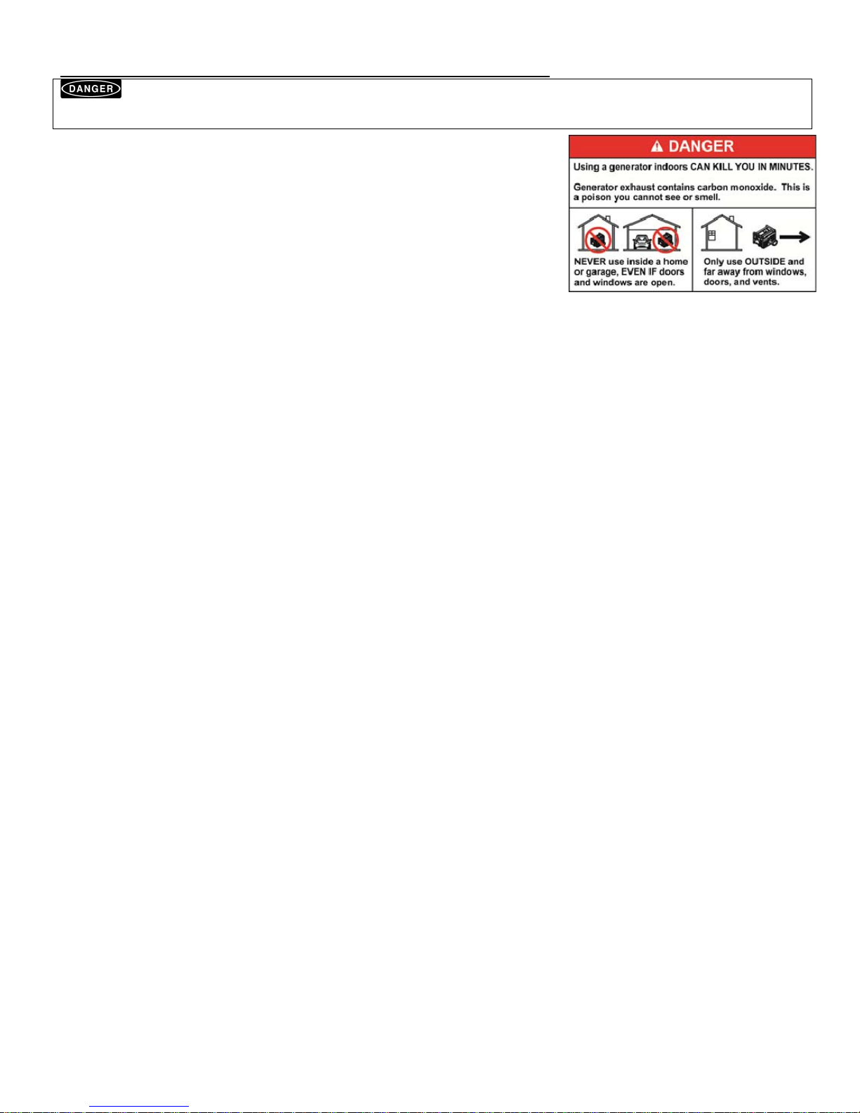
NEVER run portable generators indoors or in garages, basements, or sheds. Portable generators should always be used at least 5 feet away from windows,
doors, vents, or any other opening. Carbon Monoxide (CO) from a generator is deadly and can kill you in minutes. Read and follow all generator directions before use.
When a power failure occurs:
1. Move generator outdoors. Never operate a generator indoors or in an enclosed area.
2. Open the front and bottom covers on the transfer switch.
3. Plug generator cord into generator and the power inlet on the bottom of the transfer switch. Start generator.
4. Turn UTIL breaker OFF (down) and slide interlock mechanism over UTIL breaker.
5. Turn GEN breaker ON (up) and generator power should start to power the load(s).
When utility power is restored:
1. Turn OFF (down) the GEN breaker on transfer switch and slide the interlock mechanism over GEN breaker.
2. Turn ON (up) the UTIL breaker.
3. Turn off generator and disconnect generator cord. Cool down generator, store generator and cord in dry
location.
4. Close cover(s) on transfer switch and secure/lock as needed.
© 2012 Generac Power Systems, Inc. All Rights Reserved. GenTran and Generac are registered trademarks of Generac Power Systems, Inc. PN 50869 Rev A
2
Protected by US Patent No. US 6,861,596 B2
Generac Power Systems, Inc.
Toll Free: 1-888-GENERAC
www.generac.com
0196950SBY
Page 3

Instructions d'installation et d'utilisation
COMMUTATEUR DE TRANSFERT MANUEL MODÈLES 6375 et 6377
AVERTISSEMENT : Les commutateurs de transfert Generac®doivent être installés par un électricien professionnel qui se connaît bien en câbles et codes électriques et a de l'expérience
avec les génératrices. Generac décline toute responsabilité pour les accidents, les dommages ou les blessures causés par une installation incorrecte. Ce commutateur de transfert sera
monté en surface uniquement À L'EXTÉRIEUR. Nos commutateurs de transfert sont homologués UL selon le standard UL 1008 et répondent aux critères du Code électrique national,
article 702.6 portant sur les systèmes de secours secondaires. ATTENTION : Si vous utilisez le générateur et le commutateur de transfert pour des appareils plus grands, tels que les
chauffe-eau électriques, les sécheuses à linge, les cuisinières électriques et les petits climatiseurs, lisez les étiquettes sur les appareils pour vérifier qu'ils ne dépassent PAS la puissance
nominale du générateur. L'intensité de l'appareil ne devrait pas dépasser la puissance nominale du disjoncteur individuel du commutateur de transfert (20 ou 30 ampères).
Avertissement conformément à la California Proposition 65: L'État de Californie avertit que l'échappement du moteur et certains de ses composants peuvent causer le cancer, des
malformations congénitales ou autres anomalies de la reproduction. Ce produit peut contenir ou émettre des produits chimiques qui, selon l'État de Californie, peuvent causent le
cancer, des malformations congénitales ou autres anomalies de la reproduction.
Nous vous remercions d'avoir acheté un commutateur de transfert Generac pour brancher
une génératrice portable en toute sécurité à un circuit simple à votre maison ou à votre
bureau (monophasé seulement) pour des applications à alimentation de secours. Quelques
caractéristiques du produit :
• L'alimentation de la génératrice et de l'installation de service sont mécaniquement verrouillées pour
empêcher l'installation de service et la génératrice d'alimenter le circuit en même temps
• Ce commutateur de transfert est conçu pour être monté en surface à côté d'un centre de distribution
déjà existant et relié à un disjoncteur dans le panneau principal.
Outils et objets nécessaires pour l'installation :
• Tournevis à douille de 1/4 po et 11/32 po
• Aube droite et tournevis Phillips
• Perceuse électrique, ancrages et vis pour monter le commutateur de transfert sur le mur
• Coupe-fil / outil à dénuder
• Serre-fils
Modèle 6375 en image
TABLEAU 1 - CARACTÉRISTIQUES
MODÈLE : 6375
Taille maximum de la génératrice en watts
Intensité maximum
Configuration NEMA de l'alimentation d'entrée
Tension
Boîtier type NEMA
Phase
Calibre minimum du cordon d'alimentation
• Cordon d'alimentation pour relier la génératrice au commutateur
6377
1875 7500
15 ampères @ 125 volts 30 ampères @ 125/250 volts
5-15 L14-30
125 volts 125/250 volts
3R - Extérieur 3R - Extérieur
1 1
AWG 12/3 10/4
ÉTAPE 1 : PROCÉDURE D'INSTALLATION :
PROCÉDURES D'INSTALLATION, DE FONCTIONNEMENT ET D'ENTRETIEN CORRECTES POUR ÉVITER LES TENSIONS DANGEREUSES. ARRÊTEZ LE DISJONCTEUR PRINCIPAL DU CENTRE DE
DISTRIBUTION AVANT DE COMMENCER L'INSTALLATION.
Modèle 6375 - commutateur de transfert pour chaudière de 15 ampères
1. Le commutateur de transfert de la fournaise peut être installé sur le côté gauche ou droit du centre de distribution. Voir la figure 3. Ajustez l'unité en la
tenant contre le mur à environ 18 po du centre de distribution et marquez le lieu où se rencontrent le commutateur de transfert et l'extrémité du
faisceau dans le centre de distribution.
2. Enlevez le couvercle du centre de distribution. ATTENTION : à l'intérieur du centre de distribution il y a des niveaux dangereux de tension.
Localisez et enlevez une entrée défonçable de 1/2 po du fond du centre de distribution, à l'endroit marqué dans l'étape 1. Passez les fils du faisceau
du commutateur de transfert à travers l'entrée et installez le raccord de conduit.
3. Enlevez et gardez les deux vis fixant l'assemblage intérieur au boîtier du commutateur de transfert.
4. Soulevez et retirez l'assemblage intérieur pour faciliter l'accès aux quatre (4) trous de montage sur le dos du boîtier. Montez le boîtier du commutateur
de transfert dans la position souhaitée à l'aide des attaches fournies par l'installateur dans quatre (4) trous de montage sur le dos du boîtier.
Réinstallez l'assemblage intérieur dans le boîtier (faites attention à ne pas pincer les fils passant entre le boîtier et l'assemblage intérieur) en accrochant
la partie frontale supérieure de l'assemblage intérieur aux goujons du boîtier et en fixant l'assemblage intérieur au boîtier à l'aide des deux vis enlevées
dans l'étape 3. Maintenant, vous pouvez brancher les fils du commutateur de transfert au circuit convenable du centre de distribution.
5. Arrêtez le disjoncteur du centre de distribution que vous voulez brancher au commutateur de transfert. Desserrez la vis fixant le fil dans le disjoncteur
et enlevez le fil du disjoncteur.
6. Insérez le fil ROUGE (installation de service) du commutateur de transfert dans le disjoncteur et serrez la vis.
LES BOÎTIERS DU COMMUTATEUR DE TRANSFERT CONTIENNENT DES TENSIONS DANGEREUSES QUI PEUVENT CAUSER LA MORT OU DES BLESSURES GRAVES. SUIVEZ LES
1
Page 4

7. A l'aide d'serre-fils, reliez le fil enlevé du disjoncteur dans l'étape 5 au fil NOIR (centre de distribution) venant du commutateur de transfert.
8. Insérez et serrez le fil BLANC (neutre) du commutateur de transfert dans la barre de NEUTRE dans le centre de distribution. Insérez et serrez le fil
VERT (de masse) du commutateur de transfert dans la barre de MASSE dans le centre de distribution. S'il n'y a pas de barre de masse, insérez-la et
serrez-la dans la barre de NEUTRE.
9. Réinstallez le couvercle du centre de distribution. Mettez en service le disjoncteur arrêté dans l'étape 5. Le commutateur de transfert peut être soumis
à l'essai et mis en fonction.
Modèle 6377 - commutateur de transfert bipolaire de 30 ampères
1. Ce commutateur de transfert peut être installé sur le côté gauche ou droit du centre de distribution. Ajustez l'unité en la tenant contre le mur à environ
18 po du centre de distribution et marquez le lieu où se rencontrent le commutateur de transfert et l'extrémité du faisceau dans le centre de distribution.
2. Enlevez le couvercle du centre de distribution. ATTENTION : à l'intérieur du centre de distribution il y a des niveaux dangereux de tension.
Localisez et enlevez une entrée défonçable de 1/2 po du fond du centre de distribution, à l'endroit marqué dans l'étape 1. Passez les fils du faisceau
du commutateur de transfert à travers l'entrée et installez le raccord de conduit.
3. Ouvrez le couvercle frontal du commutateur de transfert en enlevant la vis en bas. Enlevez et gardez les deux vis fixant l'assemblage intérieur au
boîtier. Soulevez et retirez l'assemblage intérieur.
4. Si nécessaire, enlevez l'entrée défonçable sur le dos du boîtier avant de monter ce dernier. Reliez le raccord à l'entrée défonçable. Ensuite, montez le
boîtier du commutateur de transfert dans la position souhaitée à l'aide des attaches fournies par l'installateur dans quatre (4) trous de montage sur le
dos du boîtier et scellez les quatre attaches de montage.
5. Si nécessaire, enlevez l'entrée défonçable latérale et installez les raccords et le conduit convenables.
6. Tirez du fil (vert/blanc/noir/rouge) en quantité, de taille et de couleur suffisantes dans le boîtier
7. Insérez le fil BLANC (neutre) dans la cosse « W » de l'entrée de l'assemblage intérieur et serrez la vis de la cosse OU reliez-le au fil en tire-bouchon
BLANC (neutre) pratiqué à l'entrée à l'aide d'un serre-fils.
8. Utilisez des serre-fils (fournis par l'installateur) pour effectuer les connexions suivantes :
a. Reliez le fil VERT (de masse) au fil en tire-bouchon VERT (de masse) branché à l'assemblage intérieur,
b. Reliez le(s) fil(s) de l'alimentation de service ramené(s) au boîtier au(x) câble(s) ROUGE(S) marqué(s) SERVICE de l'assemblage intérieur et
c. Reliez le(s) fil(s) du centre de distribution ramené(s) dans le boîtier au(x) câble(s) NOIR(S) marqué(s) DISTRIBUTION de l'assemblage
intérieur.
9. Pliez les fils et réinstallez l'assemblage intérieur dans le boîtier (faites attention à ne pas pincer les fils passant entre le boîtier et l'assemblage intérieur)
en accrochant la partie frontale supérieure de l'assemblage intérieur aux goujons du boîtier et en fixant l'assemblage intérieur au boîtier à l'aide des
deux vis enlevés dans l'étape 2. Le commutateur de transfert peut être soumis à l'essai et mis en fonction.
DIAGRAMMES DE CÂBLAGE
2
Page 5

ÉTAPE 2 : UTILISATION DU COMMUTATEUR DE TRANSFERT :
moins 5 pieds de toute fenêtre, porte, bouche d'aération ou toute autre ouverture. L'oxyde de carbone (CO) émis par la génératrice présente un danger de mort immédiate.
Lisez et suivez toutes les indications visant la génératrice avant de l'utiliser.
En cas de panne de courant :
1. Déplacez la génératrice à l'extérieur. N'utilisez jamais de génératrice à
2. Ouvrez les couvercles frontal et inférieur du commutateur de transfert.
3. Branchez le cordon d'alimentation à la génératrice et à l'entrée d'alimentation
4. Arrêtez le disjoncteur de l'installation de service (vers le bas) et faites glisser
5. Allumez le disjoncteur de l'alimentation par génératrice (vers le haut) et la
Lorsque l'alimentation de service est reprise :
1. Arrêtez (vers le bas) le disjoncteur de l'alimentation par génératrice du
2. Allumez (vers le haut) le disjoncteur de l'installation de service.
3. Arrêtez la génératrice et débranchez le cordon de la génératrice. Laissez refroidir, puis rangez la génératrice et son cordon dans un endroit sec.
4. Fermez les couvercles du commutateur de transfert et fixez/verrouillez-les s'il y a lieu.
© Generac 2012 Power Systems, Inc. Tous droits réservés. GenTran et Generac sont des marques déposées de Generac Power Systems, Inc. 50869 Rév. A
Ne JAMAIS utiliser de génératrice portable à l'intérieur ou dans le garage, le sous-sol ou la grange. Il faut toujours utiliser les génératrices portables à au
l'intérieur ou dans un espace fermé.
en bas du commutateur de transfert. Mettez en marche la génératrice.
le mécanisme de verrouillage par dessus le disjoncteur.
génératrice devrait commencer à alimenter les charges.
commutateur de transfert et faites glisser le mécanisme de verrouillage par
dessus le disjoncteur .
Protégé par le brevet américain no. US 6.861.596 B2
Generac Power Systems, Inc.
Numéro gratuit : 1-888-GENERAC
www.generac.com
3
Page 6

Instalación e instrucciones de uso
INTERRUPTOR DE TRANSFERENCIA MANUAL - MODELOS 6375 y 6377
ADVERTENCIA: Los interruptores de transferencia Generac® deben ser instalados por un electricista profesional familiarizado con cableados y códigos eléctricos y que tenga experiencia
en trabajar con generadores. Generac no acepta responsabilidad alguna por accidentes, daños o lesiones personales causadas por una instalación incorrecta. Este interruptor de
transferencia está pensado para su instalación en superficies solo en EXTERIORES. Nuestros interruptores de transferencia están incluidos en el listado UL según la norma UL 1008 y
cumplen con los criterios del Artículo 702.6 del Código Nacional Eléctrico para Sistemas opcionales en reposo. PRECAUCIÓN: Si utiliza el generador y el interruptor de transferencia
para aparatos grandes, tales como calentadores eléctricos de agua, secarropas, fogones eléctricos, acondicionadores de aire pequeños, verifique las etiquetas de los aparatos para
asegurarse de que NO excedan la potencia del generador. Ningún aparato debe tener un amperaje que exceda la potencia individual del disyuntor en el interruptor de transferencia
(20 o 30 amps). ADVERTENCIA SOBRE LA PROPUESTA 65 DE CALIFORNIA: El Estado de California reconoce que el escape de motores y algunos de sus componentes causan cáncer,
defectos congénitos y otros daños reproductivos. Este producto puede contener o emitir sustancias químicas conocidas como causantes de cáncer, defectos congénitos y otros daños
reproductivos.
Gracias por comprar un interruptor de transferencia Generac para conectar de manera segura
un generador portátil a un único circuito en su hogar o negocio (monofásico solamente) para
aplicaciones de energía de reserva. Las características del producto incluyen:
• Alimentación principal del generador y alimentación principal de servicios interbloqueadas
mecánicamente para evitar que los servicios y el generador alimenten el circuito simultáneamente.
• Este conmutador de transferencia está destinado a montajes sobre superficie junto a un centro de
carga existente y cableado a un disyuntor en el panel principal.
Herramientas y elementos necesarios para la instalación:
• Llaves de tuercas de 1/4" y 11/32
• Destornillador de punta plana y Phillips
• Taladro eléctrico, anclajes y tornillos para montar el conmutador de transferencia a la pared
• Cortacable/pelacable
• Conectores de cables
• Cable de alimentación para conectar el generador al interruptor de transferencia
Se muestra el Modelo 6375
TABLA 1: ESPECIFICACIONES
MODELO: 6375
Tamaño máximo del generador en vatios
Amperaje máximo
Configuración NEMA del toma eléctrico
Voltaje
Caja tipo NEMA
Fase
Calibre mínimo del cable
6377
1875 7500
15 amperios a 125 voltios 30 amperios a 125/250 voltios
5 a 15 L14-30
125 voltios 125/250 voltios
3R, exterior 3R, exterior
1 1
12/3 AWG 10/4
PASO 1: PROCEDIMIENTO DE INSTALACIÓN:
EXISTEN VOLTAJES PELIGROSOS DENTRO DE LAS CAJAS DEL INTERRUPTOR DE TRANSFERENCIA QUE PUEDEN CAUSAR LA MUERTE O DAÑOS PERSONALES GRAVES. SIGA LOS
PROCEDIMIENTOS ADECUADOS DE INSTALACIÓN, USO Y MANTENIMIENTO PARA EVITAR LOS VOLTAJES PELIGROSOS. APAGUE EL DISYUNTOR PRINCIPAL EN EL CENTRO DE CARGA ANTES DE
COMENZAR LA INSTALACIÓN.
Modelo 6375: Conmutador de transferencia del horno de 15 amperios
1. El conmutador de transferencia del horno puede instalarse a la izquierda o derecha del centro de carga. Vea la Figura 3. Pruebe adecuar la unidad
2. Quite la cubierta del centro de carga. PRECAUCIÓN: Presencia de voltajes peligrosos dentro del centro de carga. Localice y retire ½" KO de la parte
3. Retire y conserve los dos tornillos que fijan el ensamble interior al encofrado del conmutador de transferencia.
4. Eleve y extraiga el ensamble interior para proporcionar acceso a los cuatro (4) orificios de montaje en la parte posterior del encofrado. Monte el
sujetando hacia arriba en la pared aproximadamente a 18" de la parte central del centro de carga y marque la ubicación del conmutador de
transferencia y el extremo del manojo de cables en el centro de carga.
inferior del centro de carga de la marca realizada en el Paso 1. Inserte el manojo de cables del conmutador de transferencia a través del KO e instale el
accesorio del conducto.
encofrado del conmutador de transferencia en la posición que desee utilizando los tensores proporcionados por el instalador a través de los cuatro (4)
orificios de montaje en la parte posterior del encofrado. Vuelva a instalar el ensamble interior en el encofrado (asegúrese de no enredar los cables
entre el encofrado y el ensamble interior) enganchando la parte superior de las conexiones aisladas del ensamble interior sobre los montantes en el
interior del encofrado y fijando el ensamble interior al encofrado con los dos tornillos que quitó en el Paso 3. Ahora está listo para conectar los cables
del conmutador de transferencia al circuito que desee en el interior del centro de carga.
1
Page 7

5. Apague el disyuntor en el centro de carga al que desea conectar el conmutador de transferencia. Afloje el tornillo que fija el cable al disyuntor y quite
el cable del disyuntor.
6. Inserte el cable ROJO (UTIL) del conmutador de transferencia en el disyuntor y ajuste el tornillo.
7. Con un conector de cables, conecte el cable que quitó del disyuntor en el Paso 5 con el cable NEGRO (LOAD) que proviene del conmutador
de transferencia.
8. Inserte y ajuste el cable BLANCO (neutro) del conmutador de transferencia a la barra de NEUTRO (NEUTRAL) en el centro de carga. Inserte y ajuste
el cable VERDE (tierra) del conmutador de transferencia a la barra de TIERRA (GROUND) en el centro de carga. Si no hay una barra a tierra, inserte
y ajústelo en la barra de NEUTRO.
9. Vuelva a instalar la cubierta del centro de carga. Encienda el disyuntor que apagó en el Paso 5. El conmutador de transferencia ahora está listo para
probar y usar.
Modelo 6377: Conmutador de transferencia de 2 polos de 30 amperios
1. Este conmutador de transferencia puede instalarse a la izquierda o derecha del centro de carga. Pruebe adecuar la unidad sujetando hacia arriba en la
pared aproximadamente a 18" de la parte central del centro de carga y marque la ubicación del conmutador de transferencia y el extremo del manojo
de cables en el centro de carga.
2. Quite la cubierta del centro de carga. PRECAUCIÓN: Presencia de voltajes peligrosos dentro del centro de carga. Localice y retire ½" KO de la parte
inferior del centro de carga de la marca realizada en el Paso 1. Inserte el manojo de cables del conmutador de transferencia a través del KO e instale el
accesorio del conducto.
3. Abra la cubierta del conmutador de transferencia quitando el tornillo cerca de la parte inferior. Retire y conserve los dos tornillos que fijan el ensamble
interior al encofrado. Eleve y extraiga el ensamble interior.
4. De ser necesario, quite el KO en la parte posterior del encofrado antes de montar el encofrado. Conecte el accesorio nuevamente al KO.
A continuación, monte el encofrado en la posición que desee con los tensores proporcionados por el instalador a través de los cuatro (4)
orificios de montaje en la parte posterior del encofrado, y selle los cuatro tensores de montaje.
5. Si corresponde, quite los KO laterales e instale los accesorios y conductos de manera adecuada.
6. Coloque la cantidad de cable del tamaño y color adecuados (verde/blanco/negro/rojo) en el encofrado.
7. Inserte el cable BLANCO (neutro) que colocó en el encofrado en el terminal "W" en la toma montada en el ensamble interior y ajuste el tornillo del
terminal O conecte la conexión en espiral BLANCO (neutro) instalada en la toma utilizando un conector de cables.
8. Utilice los conectores de cables (proporcionados por el instalador) para hacer estas conexiones:
a. Conecte el cable VERDE (tierra) colocado en el encofrado con la conexión en espiral VERDE (tierra) conectada al ensamble interior.
b. Conecte los cables UTIL colocados en el encofrado a los conductores ROJOS marcados como UTIL en el ensamble interior.
c. Por último, conecte los cables LOAD colocados en el encofrado a los conductores NEGROS marcados como LOAD en el ensamble interior.
9. Pliegue los cables y vuelva a instalar el ensamble interior en el encofrado (asegúrese de no enredar los cables entre el encofrado y el ensamble
interior) enganchando la parte superior de las conexiones aisladas del ensamble interior sobre los montantes en el interior del encofrado y fijando el
ensamble interior al encofrado con los dos tornillos que quitó en el Paso 2. El conmutador de transferencia ahora está listo para probar y usar.
DIAGRAMAS DE CABLEADO
2
Page 8
PASO 2: USO DEL CONMUTADOR DE TRANSFERENCIA:
NUNCA use generadores portátiles en interiores o en garajes, sótanos o cobertizos. Los generadores portátiles siempre deben usarse al menos a 5 pies de
distancia de ventanas, puertas, conductos de ventilación o cualquier otra abertura. El monóxido de carbono (CO) de un generador es mortal y puede matarlo en minutos.
Lea y siga todas las instrucciones del generador antes de usarlo.
En el caso de una interrupción de energía:
1. Lleve el generador al exterior. Nunca ponga en funcionamiento un generador en el interior o en un área cerrada.
2. Abra las cubiertas frontal e inferior en el conmutador de transferencia.
3. Enchufe el cable del generador y la toma de alimentación en la parte inferior del conmutador de transferencia.
Encienda el generador.
4. Apague el disyuntor UTIL (abajo) y deslice el mecanismo de interbloqueo sobre este disyuntor.
5. Encienda el disyuntor GEN (arriba); la energía del generador debería comenzar a alimentar la carga.
Cuando se restablezca el servicio energético:
1. Apague (abajo) el disyuntor GEN en el conmutador de transferencia y deslice el mecanismo de interbloqueo
sobre el disyuntor GEN.
2. Encienda (arriba) el disyuntor UTIL.
3. Apague el generador y desconecte el cable del generador. Deje enfriar el generador, almacene la unidad y el
cable en un lugar seco.
4. Cierre las cubiertas del conmutador de transferencia y asegure o bloquee según sea necesario.
© 2012 Generac Power Systems, Inc. Todos los derechos reservados. GenTran y Generac son marcas registradas de Generac Power Systems, Inc. NP 50869 Rev. A
3
Protegido por la patente de los Estados Unidos N.° US 6,861,596 B2
Generac Power Systems, Inc.
Línea gratuita: 1-888-GENERAC
www.generac.com
 Loading...