

Page 1

m
Miinual Part No. 05580
SERVICE
MANUAL
NP and IM Series
RECREATIONAL
VEHICLE &
NDUSTRIAL
MOBILE
AC GENERATORS
Liquid-Cooled
Diesel Engine Models
CORPORATION
Issued- 01A>4/93
*P. O. Box 8 *Waukesha, Wisconsin 53187
Printed in U.S.A.
Page 2

IMPORTANT SAFETY NOTICE
Proper service and repair is important to the safe, economicai and reliabie operation
of ali recreationai vehicie and industrial mobile generators. Troubleshooting, testing
and servicing procedures recommended by Generac and described in this manual are
effective methods of performing such operations. Some of these operations or proce
dures may require the use of specialized equipment. Such equipment should be used
when and as recommended.
It is important to note that the manual contains various DANGER, CAUTION and
NOTE blocks. These should be read carefully in order to minimize the risk of personal
injury or to prevent improper methods or practices from being used which could damage
equipment or render it unsafe. These DANGER, CAUTION and NOTE blocks are not
exhaustive. Generac could not possibly know, evaluate and advise the recreational
vehicle trade of all conceivable ways in which operations described in this manual might
be accomplished, or the possible hazardous consequences of each way. Consequently,
Generac has not taken any such broad evaluation. Accordingly, anyone who uses any
troubleshooting, testing or service procedure that is not recommended by Generac must
first satisfy himself that neither his nor the equipment’s safety will be jeopardized by the
procedure or method he selects.
Page 3

TABLE OF CONTENTS
#
SERVICE
MANUAL
NP and IM Series
RECREATIONAL
VEHICLE &
INDUSTRIAL
MOBILE
AC
PART
TITLE
THE REVOLVING FIELD AC GENERATOR
ENGINE MECHANICAL
ENGINE LUBRICATION AND COOLING
SYSTEM
ENGINE FUEL SYSTEM
ENGINE ELECTRICAL SYSTEM
ELECTRICAL DATA
GENERATORS
Liquid-Cooled
Diesel Engine Models
Page 4

Parti
THE REVOLVING
FIELD
AC
GENERATOR
NP and IM Series
RECREATIONAL
VEHICLE &
INDUSTRIAL
MOBILE
SECTION
1.1
1.2
1.3
1.4
1.5
1.6
1.7
1.8
1.9
TABLE OF CONTENTS
TITLE
Introduction
How a Generator Works
Major Components
(Units with 15 inch Stator)
Major Components
(Units with 10 Inch Stator)
Introduction to Troubleshooting
Troubleshooting
(Units with 15 Inch Stator)
Troubleshooting
(Units with 10 Inch Stator)
Insulation Resistance Tests
Operational Tests & Adjustments
AC GENERATORS
Liquid-Cooled Diesel Engine Models
Page 5

PARTI
THE REVOLVING FIELD AC GENERATOR
INTRODUCTION
SECTION 1.1
INTRODUCTION
Section 1.1
Service Manual Familiarization
This SERVICE MANUAL is divided into six (6)
PARTS. Each PART consists of two or more SEC
TIONS. In turn, each SECTION is divided into SUB
SECTIONS.
At the front of the manual is a main TABLE OF
CONTENTS divider page which lists the titles of Parts
1 through 6.
Each PART of the manual is also identified by a
divider page which Identifies the SECTIONS that make
up that PART.
PMes are numbered so as to identify the PART
and SECTION, as well as the specific page number.
For example, "Page 2.1-3" indicates Page 3 of Part 2,
Section 1. This type of numbering system permits indi
vidual Sections of the manual to be kept current without
affecting the entire manual.
Contents of Manual
Part 1 - The Revolving Field AC Generator
Section 1.1- Introduction
Section 1.2- How a Generator Works
Section 1.3- Major Components (Units with 15 inch
Stator)
Section 1.4- Major Components (Units with 10 inch
Stator)
Section 1.5- Introduction to Troubleshooting
Section 1.6- Troubleshooting (Units with 15 inch
Stator)
Section 1.7- Troubleshooting (Units with 10 inch
Stator)
Section 1.8- Insulation Resistance Tests
Section 1.9- Operational Tests & Adjustments
Part 2- Engine Mechanical
Section 2.1- Engine Specifications & Charts
Section 2.2- General Information
Section 2.3- Engine Disassembly
Section 2.4- Disassembly and Inspection
Section 2.5- Engine Reassembly
Part 3- Engine Lubrication & Cooling System
Section 3.1- Engine Lubrication System
Section 3.2- Water Pump and Thermostat
Section 3.3- Cooling and Ventilating Air
Section 3.4- Periodic Maintenance
Part 4- Engine Fuel System
Section 4.1- Introduction to the Diesel Fuel System
Section 4.2- Fuel Pump
Section 4.3- Governor
Section 4.4- Fuel Injection Pump
Section 4.5- Fuel Nozzles and Holders
Part 5- Engine Electrical System
Section 5.1- Introduction to DC Control Systems
Section 5.2- Engine Cranking System
Section 5.3- Battery Charge System
Section 5.4- Preheat System
Section 5.5- Engine Protective Systems
Section 5.6- Remote Radiator Fan (Model 9319)
Section 5.7- Remote Panels
Section 5.8- Troubleshooting Row Charts
Section 5.9- Troubleshooting Test Procedures
Part 6- Electrical Data
Page 6.1-1- Resistances of Rotors & Stators
Page 6.1-1- Index to Wiring Diagrams and Eiectrical
Schematics
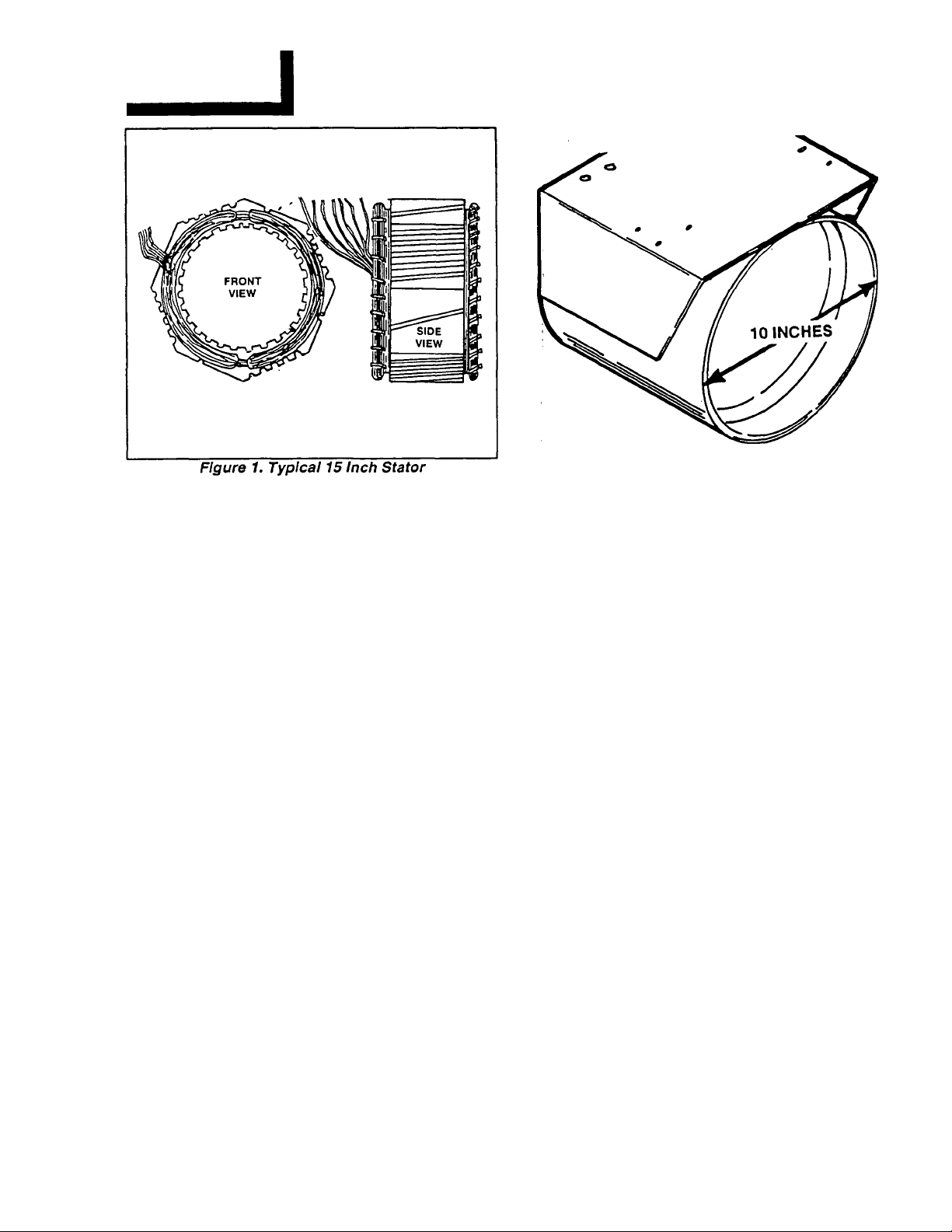
Identifying Units By Stator Diameter
Throughout the Manual, generators are identified
as having either a "15 inch" ora "10 inch" stator. These
numbers refer to the DIAMETER of the stator can
laminations. See Figures 1 and 2 on next page.
In addition to the diameter and construction of the
stator assembly, the following differences exist be
tween units with 10 inch stator and those having a 15
inch stator:
1. Units with 15 inch stator laminations are equipped
with a Part No. 67680 Voitage Regulator.
a. This type of Voltage Regulator mounts three advi
sory lamps (LED’s) which greatly simplify trouble
shooting.
b. The 67680 R^ulator requires a sensing voltage
of 240 volts AC. To provide the required 240 volts, a
step-up transformer (120 to 240 VAC) is used.
2. Units with 10 inch stator laminations are equipped
with a Part No. 81918 Voltage Regulator.
a. The 81918 Regulator mounts a single lamp (LED)
which remains on as long as sensing voltage is
available.
b. The 81918 Regulator requires a sensing voitage
of 120 volts AC and the step-up transformer is NOT
required.
Three Different Engine DC Control Sys
tems
The NP/IM series generators maybe equipped with
any one of three different kiinds of engine DC control
systems. For convenience, the three different DC sys
tems have been arbitrarily identified as Type 1, Type 2
and Type 3.
Refer to Part 5. "ENGINE ELECTRICAL SYS
TEM", for a description Type 1, 2 and 3 DC control
systems.
PAGE 1.1-1
Page 6
SECTION 1.1
INTRODUCTION
PARTI
THE REVOLVING FIELD AC GENERATOR
Figure 2. Typical 10 Inch Stator
PAGE 1.1-2
Page 7
PARTI
THE REVOLVING FIELD AC GENERATOR
HOW A GENERATOR WORKS
SECTION 1.2
HOW A GENERATOR WORKS
1
Section i.2
It has long been known that a relationship exists
General
between magnetism and electricity. The revolving field
generator (or alternator) depends on this relationship
for its operation. In order to diagnose problems and
repair a generator, the service technician must under
stand this relationship.
Why Generators Produce Electricity.
Generators produce an electrical current flow be
cause of the following laws of magnetic induction:
□ When a magnetic field is moved so that it cuts across
a conductor, a voltage and current flow are induced
into the conductor.
□ When current flows through a conductor, a magnetic
field is created around that conductor.
MAGNETIC FIELD CREATES A VOLTAGE;
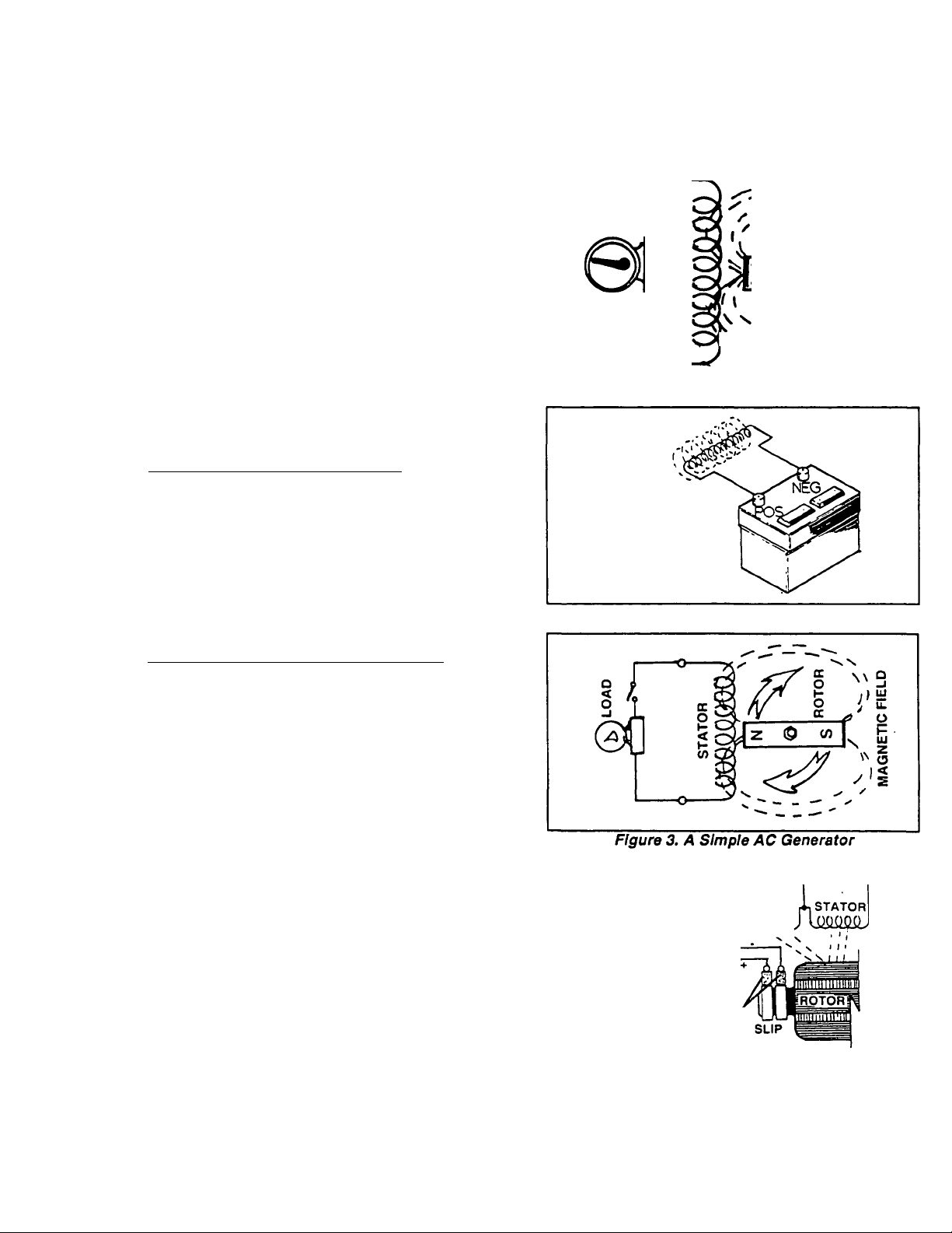
See Figure 1. When a wire, or coil of wire, is moved
through a magnetic field, an electromotive force (EMF)
or voltage is induced into the wire. Conversely, move
ment of the magnetic field so that its lines of flux cut
across the wire will induce a voltage into the wire. If the
ends of the wire are connected to form a complete
circuit, current will flow in the wire. The direction in
which the current flows depends on the polarity of the
magnetic field and the direction in which the magnet is
moved.
11
Z-
oCOIi
K
11
Figure 1. Magnetism Creates Electricity
Figure 2. Current Flow Creates a Magnetic Field
------
CURRENT FLOW CREATES A MAGNETIC FIELD:
See Rgure 2. Current flow through a wire or coil of
wire will create a magnetic field around the wire. The
strength of the magnetic field depends on the amount
of current flow and the number of loops or coils in the
wire. The direction (polarity) of the magnetic field de
pends on the direction of current flow through the wire.
A Simple AC Generator
See Figure 3. In the simple generator shown, the
revolving magnetic field (Rotor) is a permanent mag
net. As the magnet rotates, its magnetic lines of flux cut
across a stationary coil of wire called a STATOR. If the
stator circuit is completed (by adding a load such as the
light bulb), current will flow through the circuit.
A More Sophisticated Generator
In Figure 4, direct current (DC) is delivered to the
ROTOR coil through CARBON BRUSHES and SLIP
RINGS, to create a magnetic field around the ROTOR.
The greater the current flow through the ROTOR wind
ings, the stronger the magnetic field around the
ROTOR. The ROTOR’S magnetic field cuts across the
stationary STATOR windings, to induce a voltage into
those windings, with the induced voltage proportional
to the strength of the ROTOR’S magnetic field.
STATOR
Û. T 1«V.
üэ”r^
¿»V.
< o
z
UJ-
a.
oc
u 3
ou
Figure 4. A More Sophisticated Generator
BRUSHES
RINGS
PAGE 1.2-1
Page 8
SECTION 1.2
HOW A GENERATOR WORKS
Operational Analysis- Units with 10 inch Stator Laminations
NOTE: See "IDENTIFYING UNITS BY STATOR DIAMETER" on Page 1.1-1.
PARTI
THE REVOLVING FIELD AC GENERATOR
1
Generator Operation may be briefly described as
follows:
CZl The ROTOR is attached to the engine PTO shaft
and rotates at the same speed as the engine.
□ As the Rotor turns, its magnetic lines of flux cut
across the stationary coils of (a) a stator excitation
winding and (b) dual stator AC power windings. A
voltage is induced into these stationary windings.
□ Current flow from the Stator excitation winding is
delivered to the Voltage Regulator as unregulated
alternating current.
□ Current flow from the Stator AC power windings is
delivered to connected electrical loads.
□ Sensing leads deliver a signal of ACTUAL power
winding output voltage to the Voltage Regulator,
from the Stator AC power windings.
□ The Voltage Regulator electronically compares the
ACTUAL power winding voltage to a REFERENCE
voltage which was pre-set.
□ If the ACTUAL power winding voltage is less than the
Regulator’s REFERENCE voltage. Regulator action
will (a) change the excitation winding output to direct
current (DC), and (b) increase the excitation current
flow to the Rotor.
□ If the ACTUAL power winding voltage is more than
the Regulator’s REFERENCE voltage, regulator ac
tion will (a) change the excitation current to direct
current, and (b) decrease excitation current to the
Rotor.
□ The regulated direct current flow to the Rotor is
delivered via brushes and slip rings.
□ A regulated voltage is induced into the Stator AC
power windings as the Voltage Regulator acts to
maintain an ACTUAL voltage as close as possible to
an adjusted REFERENCE voltage.
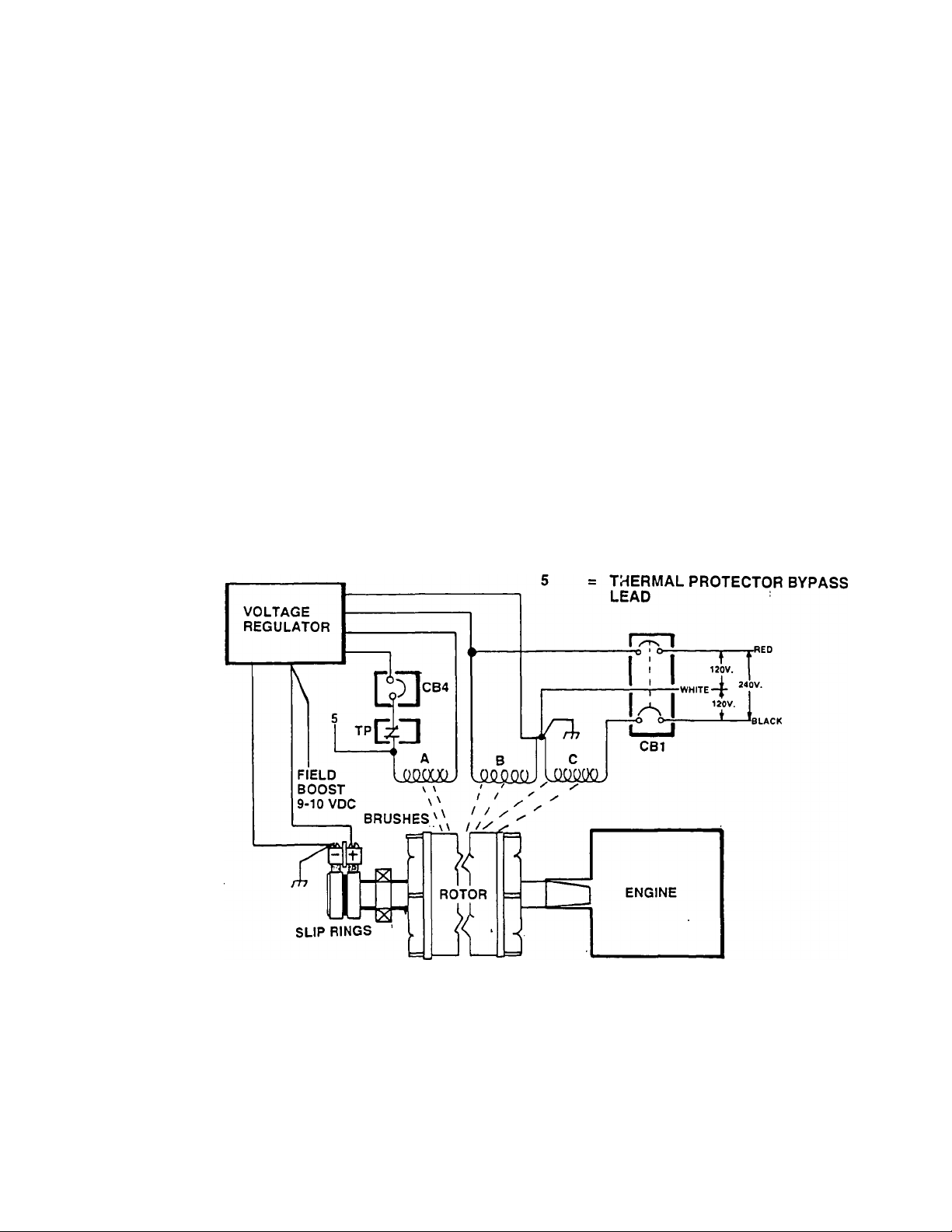
A = EXCITATION WINDING
B = STATOR AC POWER WINDING
C = STATOR AC POWER WINDING
CB1 = MAIN CIRCUIT BREAKERS
CB4 = EXCITATION CIRCUIT BREAKER
TP = THERMAL PROTECTOR
PAGE 1.2-2
Figure 5. Operating Diagram- Units with 10 Inch Stator Laminations
Page 9
PART 1
THE REVOLVING FIELD AC GENERATOR
Operational Analysis- Units with 15 Inch Stator Laminations
Some differences exist between generator models
having a 10 inch diameter stator and those with a 15
inch diameter Stator. You may wish to review "IDENTI
FYING UNITS BY STATOR DIAMETER" on Page 1:1-
1.
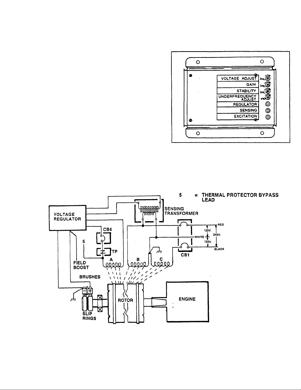
Figure 6 is an Operating Diagram for NF eries
generators with a 15* inch diameter stator. T units
are equipped with a Part No. 67680 voltagi n rewhich requires 240 volts AC sensing. Tf ram,
SENSING TRANSFORMER serves to itor’s
stator’s line-to-neutral sensing voltage to 24 ts.
SECTION 1.2
HOW A GENERATOR WORKS
1
Figure 7. Voltage Regulator Part No. 67680
m
A = EXCITATION WINDING
B = STATOR AC POWER WINDING
C = STATOR AC POWER WINDING
CB1 = MAIN CIRCUIT BREAKERS
CB4 = EXCITATION CIRCUIT BREAKER
TP = THERMAL PROTECTOR
Operating Diagram- Units with 15 Inch Diameter Stator Laminations
PAGE 1.2-3
Page 10

SECTION 1.2
HOW A GENERATOR WORKS
PARTI
THE REVOLVING FIELD AC GENERATOR
1
PAGE 1.2-4
Page 11
PARTI
THE REVOLVING FIELD AC GENERATOR
MAJOR COMPONENTS
(UNITS WITH 15 INCH DIAMETER STATOR)
SECTION 1.3- MAJOR COMPONENTS
(UNITS WITH 15 INCH STATOR)
1
Section 1.3
ITEM
QTY DESCRIPTION
1
2 4
3
4 1 Rear Bearing Carrier
5
6 1
7 1
8 10
9 6
10 4 Hex Head Flanged Bolt
11 4 Screw
12
13 1 Flexible Coupling
14
15 1 Flywheel
16
17 1 Air Ring Baffle
18 4 Vibration Mount
19 6
20 2 Socket Head Capscrew
4 Taptite Screw
4 Stud
1
4
1
4 Hex Head Capscrew
Taptite Screw
Rotor Bearing
Rotor Assembly
Stator Assembly
Hex Head Capscrew
Lockwasner
Lockwasher
Fan Ring
Flatwasher
»
2®
ITEM
21
22
23
24
25
26
27 8 Lockwasher
28
29
30
31
32 4
33
34 4
35
36
37 1
38
39
40
QTY
■ 1
DESCRIPTION
1
1
4'
2
2
2
6
4
2
2
4
1
1
4
2
Battery Cable Boot
Starter Motor
Engine Adapter
Hex Head Capscrew
Vibration Isolator
Flatwasher
Hex Head Screw
Hex Nut
Brush
Brush Holder
Screw
Brush Cover
stud
Flanged Nut
Red Starter Cable
Lockwasher
Hex Nut
Lockwasher
Hex Head Capscrew
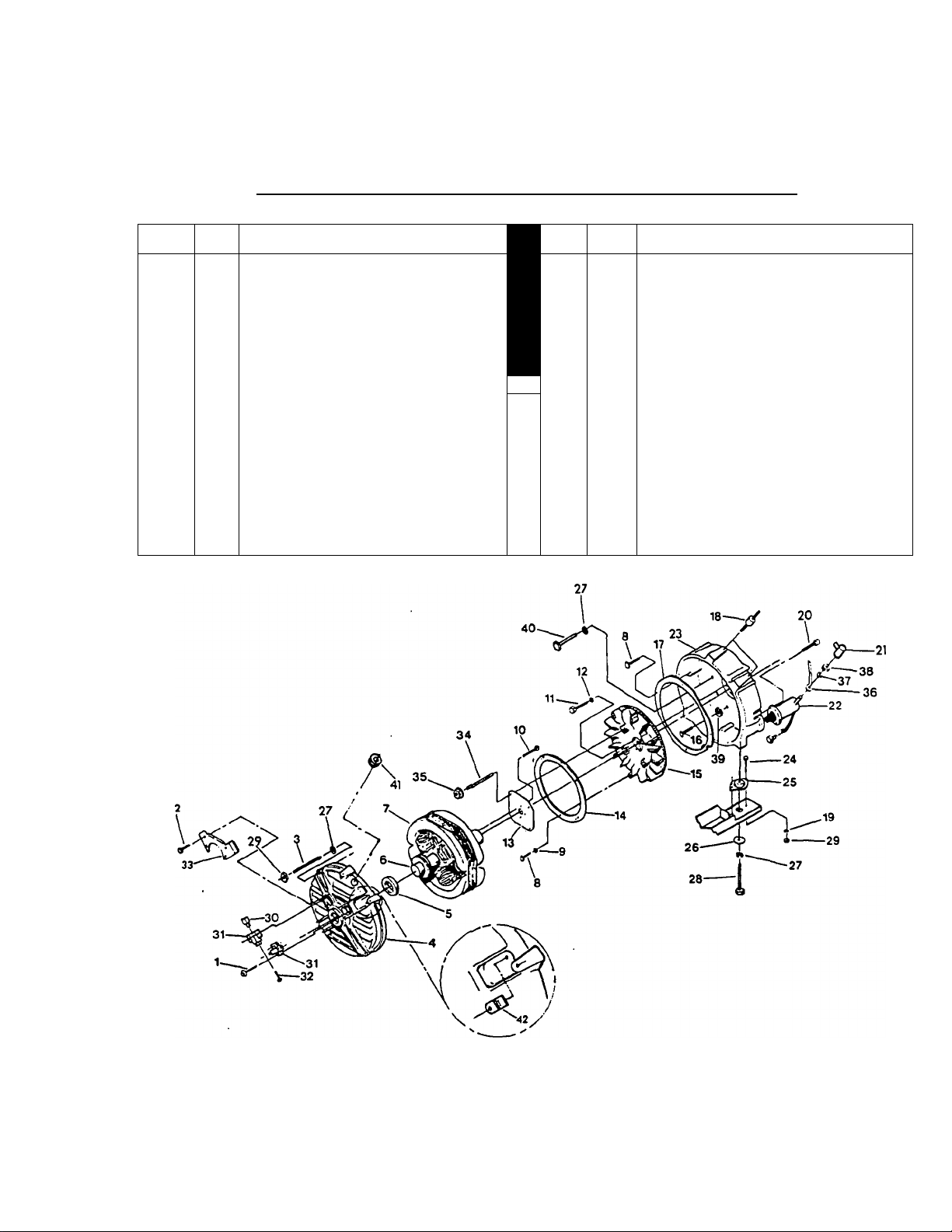
Figure 1. Exploded View of AC Generator with 15 Inch Stator
PAGE 1.3-1
Page 12
SECTION 1.3- MAJOR COMPONENTS
(UNITS WITH 15 INCH STATOR)
1
AC Generator Disassembly
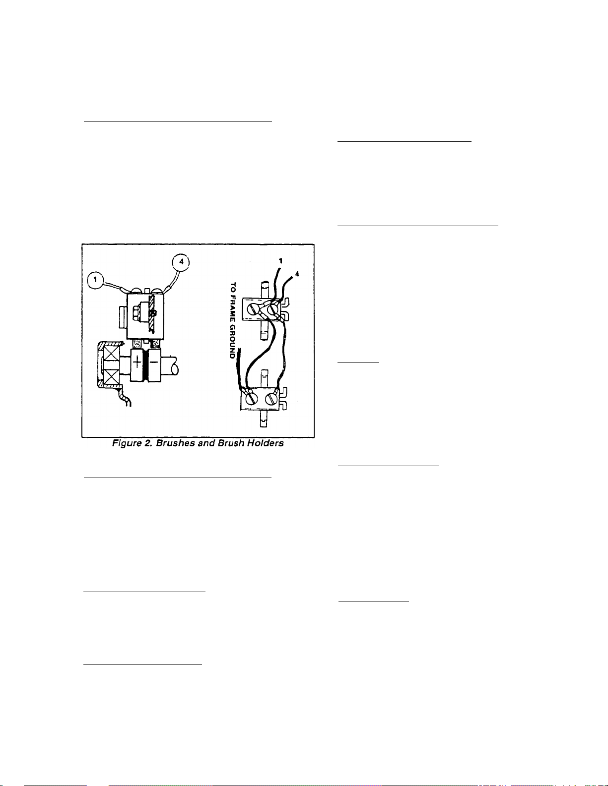
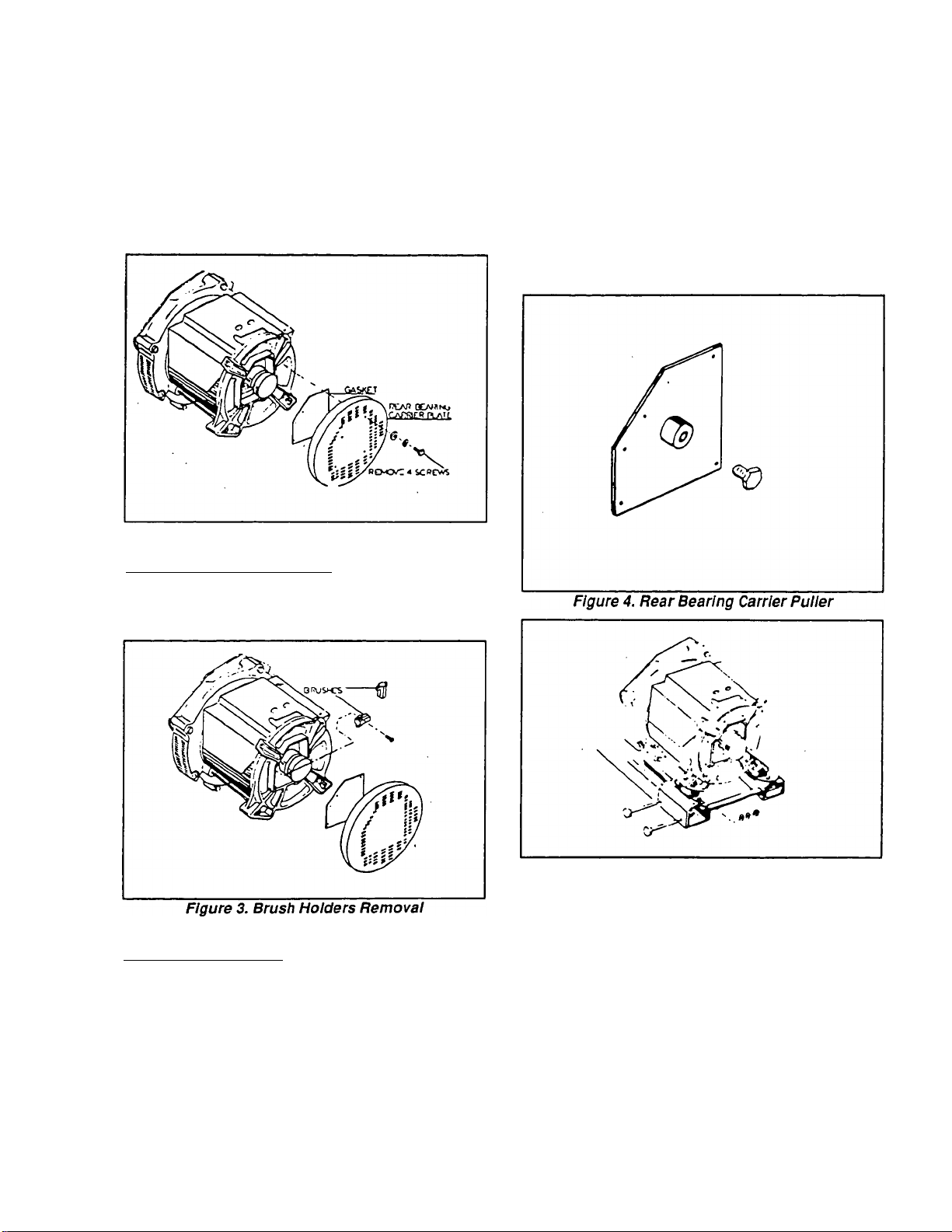
BRUSH ACCESS AND REMOVAL Figures 1 & 2);
See Rgure 1. Remove the TAPTITE SCREWS
(Item 2) that retain the two BRUSH COVERS (Item 33)
to the REAR BEARING CARRIER (Item 4). Remove
the BRUSH COVERS (Item 33) to gain access to the
BRUSH HOLDERS (Item 31).
See Figure 2, below. Remove Wires No. 1 and 4
from the BRUSHES in both BRUSH HOLDERS. Re
move the TAPTITE SCREWS that retain the BRUSH
HOLDERS to the REAR BEARING CARRIER. Re
move both BRUSH HOLDERS, along with the
BRUSHES
PARTI
THE REVOLVING FIELD AC GENERATOR
To remove the FLEXIBLE COUPLING (Item 13)
from the ROTOR (Item 6), remove four HEX HEAD
FLANGED BOLTS (Item 10).
FLYWHEEL REMOVAL (Figure 1):
Remove four SCREWS (Item 11) and
LOCKWASHERS (Item 12). Then, remove FLY
WHEEL (Item 15). If desired, the FAN RING (Item 14)
can be removed by removing HEX HEAD
CAPSCREWS (Item 8) and LOCKWASHERS (Item 9).
ENGINE ADAPTER REMOVAL (Figure 1);
To remove AIR RING BAFFLE (Item 17), remove
CAPSCREWS (Item 8) that retain It to the ENGINE
ADAPTER (Item 23).
Support the engine and remove all fasteners that
retain the ENGINE ADAPTER to the BASE ASSEM
BLY. Remove HEX HEAD CAPSCREWS (Item 40) and
LOCKWASHERS (Item 27). Finally, remove the EN
GINE ADAPTER.
Components Inspection and Testing
REAR BEARING CARRIER REMOVAL (Figure 1):
Remove HEX NUTS (Item 29), LOCKWASHERS
(Item 27) and STUDS (Item 3) that retain the REAR
BEARING CARRIER (Item 4). To free the REAR
BEARING CARRIER (Item 4) from the ROTOR BEAR
ING (Item 5), use a soft mallet to tap around the outer
periphery of the BEARING CARRIER. Continue tap
ping until the BEARING CARRIER is free of the bear
ing.
STATOR REMOVAL (Figure 1):
The STATOR (Item 7) is "sandwiched" between the
ENGINE ADAPTER (Item 23) and the REAR BEARING
CARRIER (Item 4). Carefully remove the STATOR
(Item 7). DO NOT PERMIT THE STATOR TO DROP
OR BUMP THE ROTOR DURING REMOVAL.
ROTOR REMOVAL (Figure 1):
Remove the four FLANGED NUTS (Item 35) from
STUDS (Item 34). The ROTOR (Item 6), with FLEXI
BLE COUPLING (Item 13) attached, can now be pulled
free of the FLYWHEEL (Item 15).
GENERAL;
Following disassembly, generator components
should be cleaned, dryed and inspected or tested.
Never reassemble a generator having defective parts.'
Keep major parts separated and keep the mounting
hardware along with the parts they are used with. Store
parts in a clean, dry area where condensation, dirt, or
moisture will not damage them.
REAR BEARING CARRIER:
The Rear Bearing Carrier (Figure 1, Item 4) is an
aluminum casting. Clean the casting and blow dry with
air. Inspect carefully for cracks, obvious damage. An
insert has been pressed into the Carrier center bore, to
accommodate the Rotor Bearing. Replace the Rear
Bearing Carrier if the center bore diameter is not within
the following dimensions:
BEARING CARRIER CENTER BORE
2.9527-2.9533 Inches (74.999-75.014mm)
ROTOR BEARING:
The rotor bearing is a prelubricated and sealed ball
bearino that requires no additional lubrication for the
life of the bearing. Spin the Rotor bearing by hand and
check it for binding, seizing, roughness, etc. If the
bearing is defective, it must be replaced.
The bearing may be removed from the Rotor shaft
using a bearing puller. A new bearing can then be
pressed onto the shaft. Exert pressing force on the
bearing inner race only- NEVER on the bearing outer/'"~^^
race.
PAGE 1.3-2
Page 13

PART 1
THE REVOLVING FIELD AC GENERATOR
SECTION 1.3- MAJOR COMPONENTS
(UNITS WITH 15 INCH STATOR)
1
Components Inspection and Testing
(Continued)
ROTOR ASSEMBLY;
Clean the Rotor with dry, low pressure air (25 psi
or less). If the slip rings are dirty or tarnished, clean
them with fine sandpaper. Inspect the Rotor for dam
age.
Check the resistance of Rotor windings with a
volt-ohm-milliammeter (VOM). Refer to Section 1.6,
"TROUBLESHOOTING (UNITS WITH 15 INCH STA
TOR)".
Use an Insulation resistance tester, megohmmeter,
or Hi-Pot tester to test the resistance of Rotor insula
tion. See Section 1.8,
TESTSr.
If the Insulation resistance is low, dry the Rotor with
warm, dry air. DO NOT EXCEED 185* F. (85’ C.). If
resistance is still low after drying, replace the Rotor
Assembly.
STATOR ASSEMBLY:
Clean the Stator Assembly in the same manner as
the Rotor was cleaned. Inspect ther Stator for damage.
Use a VOM to check Stator windings resistance
(see Section 1.6).
Check the insulation resistance of Stator windings,
as outlined in Section 1.8.
FLEXIBLE COUPLING:
Carefully inspect the Flexible Coupling (Figure 1,
Item 13) for damage, cracking. Check mounting holes
on couplino for elongation and damage. Replace the
Coupling, if it is damaged.
FAN RING AND AIR RING BAFFLE:
Inspect the Fan Ring (Figure 1, Item 14) and the
Air Ring Baffle (Item 17) for damage, cracking. Re
place, if damaged.
•INSULATION RESISTANCE
Reassemble the generator In the reverse order of
Generator Reassembly
disassembly. The reassembly process requires a great
deal of care. Components must be properly aligned and
retained. Tighten all fasteners to the recommended
torque values (see Part 6, "SPECIFICATIONS AND
CHARTS"). Following reassembly, perform an opera
tional test of the unit (Section 1.9).
Components In Generator Control Panel
INTRODUCTION:
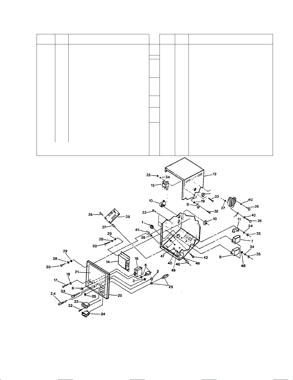
Rgure 3 (next page) Is an exploded view of the
generator control panel. The Panel houses or mounts
several Important AC generator components, as well
as components that are part of the engine DC electrical
systems.
ENGINE ELECTRICAL SYSTEM COMPONENTS;
The Control Panel houses the following compo
nents that are part of the engine electrical system. For
Information on these components, refer to Part 5 of this
Manual, "ENGINE ELECTRICAL SYSTEM".
□ The 14 and 30 amp Fuses (Items 4 and 5).
□ The 10 amp DC Circuit Breaker (Item 6).
□ The two 12 volts DC Relays (Items 7 and 8).
□ The DC Voltage Regulator (Item 13).
□ Engine Control Circuit Board (Item 39).
□ Hourmeter (Item 23).
□ Start-Stop Switch (Item 24).
□ Preheat Switch (Item 25).
AC GENERATOR COMPONENTS:
The following components, housed in the control
panel, are major generator components and will be
discussed in this Section and Sub-Section.
□ Excitation Circuit Breaker (Item 11).
□ AC Voltage Regulator (Item 14).
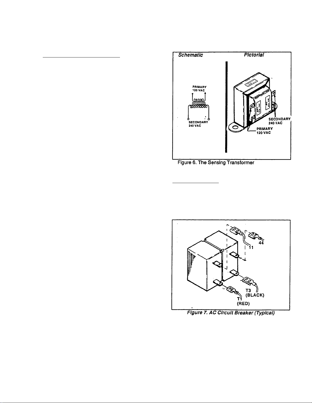
□ The Sensing Transformer (Item 15).
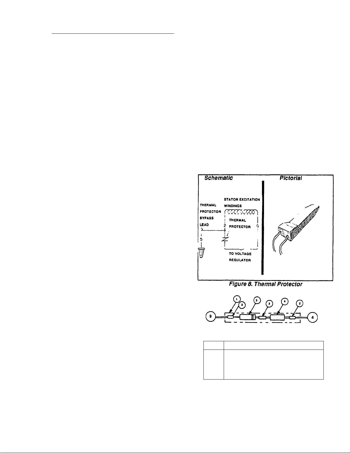
□ AC Circuit Breaker (Item 16).
FLYWHEEL;
Clean the flywheel. Inspect for damage, cracks,
wear, etc. Replace, if necessary.
ENGINE ADAPTER;
Clean the Engine Adapter (Figure 1, Item 23).
Inspect the Adapter carefully for damage, wear, crack
ing, etc. Replace, if necessary.
BRUSH HOLDERS AND BRUSHES:
Inspect Brush Holders and Brushes for damage,
cracking, chipping, excessive wear, etc. Replace any
defective or damaged part. Brushes must always be
replaced in complete sets.
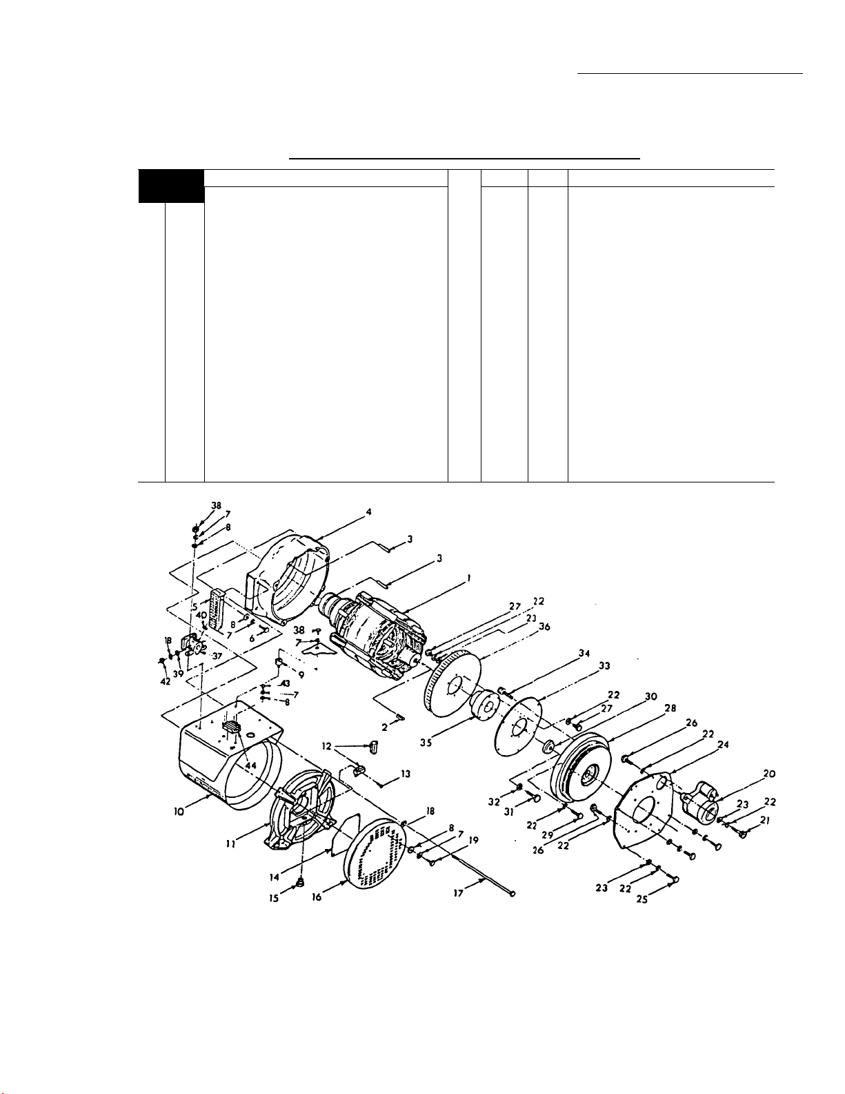
In addition to the above components, a THERMAL
PROTECTOR is physically imbedded in the wire wind
ings of the Stator Assembly. A discussion of this com
ponent will also be included in this Section.
EXCITATION CIRCUIT BREAKER;
The excitation circuit breaker is housed in the con
trol panel and connected in series with .the Stator
Excitation winding output to the Voltage Regulator.
If this Breaker should open, loss of unregulated
excitation current to the Regulator will occur. The Reg
ulator will then shut down and loss of regulated excita
tion current to the Rotor will occur. Generator AC output
will then be proportional to Rotor residual magnetism
only (about 2-7% of rated voltage).
PAGE 1.3-3
Page 14
SECTION 1.3- MAJOR COMPONENTS
(UNITS WITH 15 INCH STATOR)
PARTI
THE REVOLVING FIELD AC GENERATOR
1
ITEM
QTY
1
2*
3* 1
4*
5*
6*
r 1
8*
9
10 1
11** 1
12
13*
14“
15“
16
17
18
19
20 1
21 1
22 2
* See Part 5,
2
1
1
1
1
1
1
EXCITATION CIRCUIT BREAKER
1
1
1
1
1
4
4
1
'* Part of AC generator circuit, Included in this Section.
"ENGINE ELECTRICAL SYSTEM".
DESCRIPTION
Snap Bushing
FUSE HOLDER- 30 amp
FUSE HOLDER-14 amp
30 AMP FUSE
14 AMP FUSE
10 amp DC Circuit Breaker
12 volts DC RELAY
12 volts DC RELAY
Solderless Lug
90 Conduit Clamp
Control Panel Box
DC VOLTAGE REGULATOR
AC VOLTAGE REGULATOR
SENSING TRANSFORMER
AC CIRCUIT BREAKER
Pan Head Screw
Lockwasher
Lockwasher
Control Panel
Panel Decal
Pan Head Screw
ITEM
23* 1
24* 1
25*
26 2
27
28
29
30
31
32 1
33
34
35
36
37 4
39*
40
41
42 2
44 1
45
46
47
48
QTY
1
2
10
8
8
•
8 Pan Head Screw
8
8
4
1
6
2
1
4
4
4
DESCRIPTION
HOURMETER
START-STOP SWITCH
PREHEAT SWITCH
Hex Head Capscrew
External Lockwasher
Lockwasher
Flatwasher
Hex Head Capscrew
Customer Leeds (Not Shown).
Pan Head Screw
Lockwasher
Hex Nut
Self Tapping Screw
ENGINE CONTROL CIRCUIT
Spacer Tlut
BOARD
Lockwasher
Hex Nut
Hex Head Capscrew
Panel Wiring Harness
Engine Wire Harness
Vibration Dampener
Hex Nut
Flatwasher
Figure 3. Exploded View of Control Panel
/ 13
PAGE 1.3-4
Page 15
PARTI
THE REVOLVING FIELD AC GENERATOR
Components In Generator Control Panel (Continued)
AC VOLTAGE REGULATOR:
The Voltage Regulator is powered by stator excitation
winding AC output. Approximately 4 to 8 volts is required
from that power source to turn the regulator on.
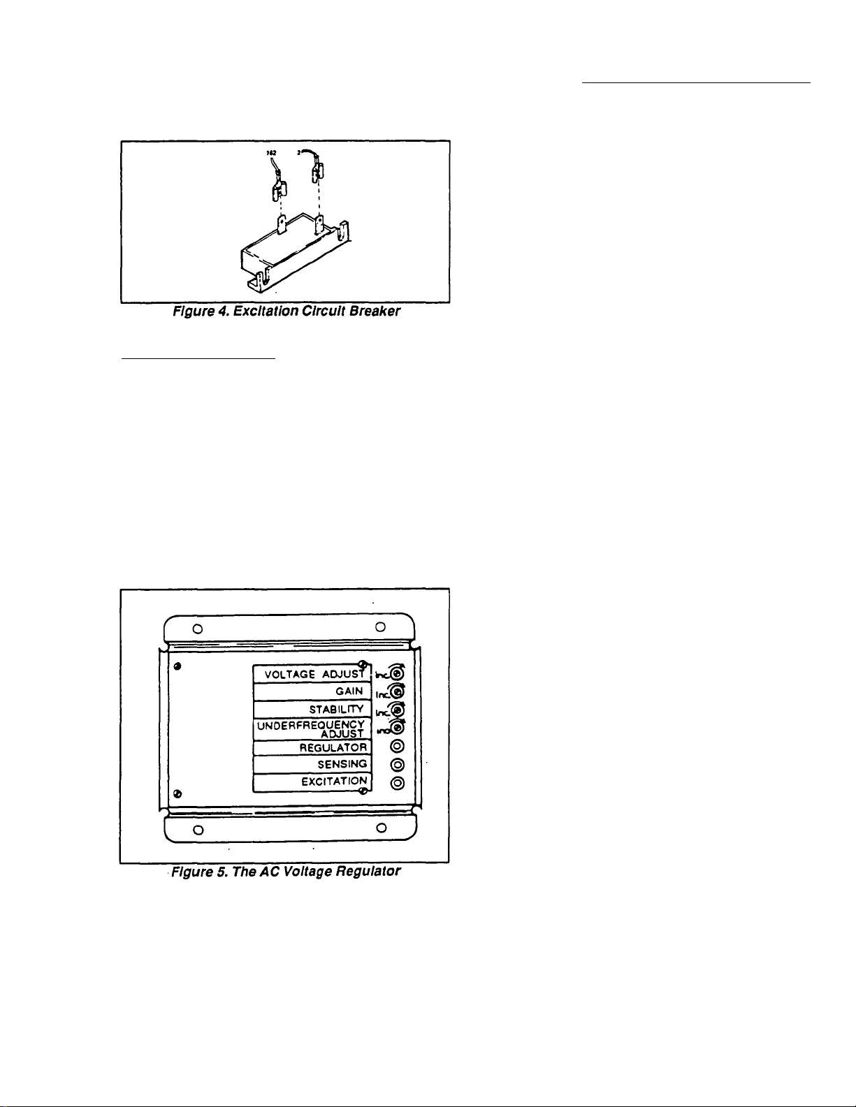
The Regulator is equipped with three (3) lamps
(LED’s or "light emitting diodes). See Figure 5. These
lamps are normally on during operation with no faults in
the system. The green EXCITATION lamp and the red
REGULATOR lamp are both turned on by stator excita
tion winding output. If, for any reason, stator excitation
winding output were to be reduced, the two lamps would
begin to dim. Finally, at some mid-point voltage and
current, the two lamps will no longer glow visibly.
SECTION 1.3- MAJOR COMPONENTS
(UNITS WITH 15 INCH STATOR)
1
NOTE: Sensing input to the Regulator Is actually taken
from Hne-to-neutra! stator leads and Is about 120 volts
AC. However, this voltage Is boosted to about 240 volts
AC by the action of a sensing transformer.
The following facts apply to Voltage Regulator opera
tion:
1. The Regulator will shut down on occurence of one or
more of the following conditions:
a. Loss of sensing voltage.
b. Loss of stator excitation voltage Input to the
Regulator.
c. Loss of circuit reference.
NOTE: The term "circuit reference" refers to voltage
regulator settings. The Regulator "regulates" excitation
winding current flow to the Rotor windings in order to
maintain a sensing (actual) voltage that Is commen
surate with a preset "reference" voltage. The reference
voltage is adjustable within a 20 percent range at the
Regulator. Voltage regulation Is accomplished by
electronically maintaining an ACTUAL voltage that Is
very close to the Regulator's preset REFERENCE volt
age.
The yellow SENSING lamp Is powered by sensing
input to the Regulator from the stator AC power wind
ings. The brightness of this lamp (LED) will depend on
available sensing voltage.
2. During generator operation, all three Regulator lamps
should be ON.
a. REGULATOR lamp ON Indicates the Regulator is
functioning normally.
b. SENSING lamp ON indicates that normal sensing
voltage Is available to the Regulator.
c. EXCITATION lamp ON Indicates that unregulated
excitation winding output Is available to the
Regulator.
3. If the red REGULATOR lamp is OUT, a Voltage
Regulator fault exists or the Regulator has shut down
due to occurence of one or more Regulator shutdown
conditions. See Step 1 above for conditions that will
result in Regulator shutdown.
a. Expect to see a generator AC output voltage that
is commensurate with the Rotor’s residual mag
netism.
b. Rotor residual magnetism will supply approximate
ly 2 to 7 percent of the unit’s rated voltage.
NOTE: "Residual" magnetism Is that magnetism that Is
normally always present In the Rotor. The Rotor may be
considered a "permanent magnet".
PAGE 1.3-5
Page 16
SECTION 1.3- MAJOR COMPONENTS
(UNITS WITH 15 INCH STATOR)
1
Components In Generator Control Panel (Continued)
AC VOLTAGE REGULATOR (CONT’D):
4. If the green EXCITATION lamp goes out, loss of
stator excitation winding output to the Regulator has
occured.
a. Loss of excitation winding output will result in
Regulator shutdown. The red REGULATOR lamp will
then go out, as well.
b. Under this condition, look for a generator AC output
voltage that is commensurate with residual Rotor
magnetism (about 2-7% of rated volts).
c. When the REGULATOR and EXCITATION lamps
are both out, the excitation circuit from the stator
excitation windings to the voltage regulator Is suspect
(inclusive).
5. Should the yellow SENSING lamp go out, loss of
sensing voltage to the Regulator has occured.
a. Loss of sensing may cause the Regulator to shut
down. Both the SENSING lamp and the
REGULATOR lamp will then go out.
b. Generator AC output voltage will then be commen
surate with Rotor residual magnetism (2-7% of rated
volts).
c. Look for a fault in the sensing circuit.
6. If all three lamps go out, look for a fault that might
cause both sensing and excitation to fail.
a. Look for dirty or corroded slip rings, bad brushes,
defective Rotor.
b. Look for open circuit in Wires No. 1 and/or 4.
7. If the red REGULATOR lamp flashes, the
Regulator’s STABILITY potentiometer requires ad
justment.
PART 1
THE REVOLVING FIELD AC GENERATOR
AC CIRCUIT BREAKER:
The AC circuit breaker protects the unit against cur
rent overload by opening the AC output circuit in the
event the generator’s current (amperage) capacity is,/'”^
exceeded. The amperage at which the breaker will trip
(open) is the breaker’s trip rating.
SENSING TRANSFORMER:
The Part No. 67680 Voltage Regulator requires a
"line-to-line" sensing voltage (240 volts) for proper
operation. However, the sensing Is taken from "line-toneutral" Wires No. 11 and 22 (120 volts). For that
reason, the primary coil of a sensing transformer is
connected in series with the sensing leads. The sensing
transformer is a "step-up" type. That is, 120 volts AC in
its primary coil will induce 240 volts into its secondary
coil. It is the secondary coil voltage that is delivered to
the regulator as sensing voltage.
The sensing transformer is housed in the generator
control panel and is used on generator’s with the Part
No. 67680 Voltage Regulator and with 15 inch diameter
stator laminations.
The sensing transformer Is shown pictorially and
schematically in Figure 6.
PAGE 1.3-6
The AC circuit breaker used on any specific generator
model will depend on the rated current (amperage)
capacity of that model.
Page 17
PART 1
THE REVOLVING FIELD AC GENERATOR
Thermal Protector !
A Thermal Protector is physically imbedded in the
wire windings of the Stator and electrically connected In
series with the excitation winding output leads to the
Regulator. The device is a normally-closed (N.C.),
temperature sensitive switch. The switch contacts will
open when stator temperatures exceed a safe level. The
switch is self resetting. That Is, it will re-dose when
stator temperatures decrease to a safe level.
If the switch contacts should op>en, excitation winding
AC output to the Voltage Regulator will be terminated
and the Regulator’s green EXCITATION lamp will go
out. Since the Regulator cannot op>erate without excita
tion winding output, the red REGULATOR lamp will also
go out. Generator AC output voltage will then drop to a
value commensurate with the Rotor’s residual mag
netism.
If the Thermal Protector contacts open during opera
tion due to a stator overtemperature condition, the
cause of the overtemperature condition must be found
and corrected. High Internal stator temperatures can be
caused by any one of the following:
SECTION 1.3- MAJOR COMPONENTS
(UNITS WITH 15 INCH STATOR
1
rings. The direct current (approximately 9-10 volts DC)
flows through the Rotor windings, the negative (-) slip
ring and brush, and to ground.
Field boost current creates a magnetic field strength
that is additive to the Rotor’s residual magnetism. The
Increased magnetic field strength during engine crank
ing provides an early "pickup* voltage In the stator. The
Regulator is turned on more quickly and AC output
occurs sooner. In effect, field boost current "flashes the
field" on every startup.
Failure of the field boost system nr^y or may not result
In a reduction of AC output to that produced by residual
Rotor magnetism. If residual magnetism Is adequate to
turn the Regulator on and provide the required pickup
voltage, the generator will operate normally with or
without field boost. However, if residual magnetism Is
not adequate, generator AC output will not build and will
be comrr^nsurate with Rotor residual magnetism.
D Insufficient cooling air flow into the generator
interior. Look for blockage of cooling air inlet/outlet openings, air openings that are too small,
ambient temperatures that are too high, etc.
□ Exceeding the wattage/amperage capacity of the
generator. If the unit is overloaded for a period of
time, internal stator temperatures can rise quickly
and cause the Thermal Protector contacts to
open.
D A shorted condition in the generator stator wind
ings or in an electrical load connected to the
generator’s AC output.
The Thennal Protector is not accessible and cannot
be removed and replaced. If the device has failed open,
it can be bypassed by connecting excitation lead No. 2
to a bypass lead (Wire No. 5). Once the device has been
bypassed, stator overtemperature protection Is no
longer available.
Field Boost
When the generator engine Is cranked, direct current
(DC) Is delivered to the Rotor windings. The cunent flow
is provided by the action of an Engine Control circuit
board housed In the control panel and Is delivered to the
Rotor via Wire No. 9, a Field Boost Resistor (R2), a Field
Boost Diode (D2), Wire No. 4, and the brushes and slip
PART OF CONTROL PANEL
WIRING HARNESS
rrSM
1
• 2
3
4
Figure 9. The Field Boost Circuit
DIODE-600V., 6 AMP
RESISTOR-5 WATT. 10 OHMS
DESCRIPTION
HEAT SHRINK
BARREL LUG
PAGE 1.3-7
Page 18

SECTION 1.3- MAJOR COMPONENTS
(UNITS WITH 15 INCH STATOR)
PARTI
THE REVOLVING FIELD AC GENERATOR
1
PAGE 1.3-8
Page 19
PARTI
THE REVOLVING FIELD AC GENERATOR
MAJOR COMPONENTS
(UNITS WITH 10 INCH STATOR)
SECTION 1.4- MAJOR COMPONENTS
(UNITS WITH 10 INCH STATOR)
1
Section 1.4
l~47.ir>r« description
■ n Rotor Assembly
n
2
3 2
4 1
5
6
7
8
9
10
11
12 2
13
14
15 1
16 1
17
18 6
19
20 1
21
22
1
1
4
16
12
4 Vibration Dampener
1 Stator Assembly
1 Rear Bearing Carrier
4
1
4
4 Capscrew
2
33
Drive Key
Dowel Pin
Blower Housing
Air Outlet Screen
Hex Head Capscrew
Lock Wasner
Flat Washer
Brush Holder
Hex Head Capscrew
Bearing Carrier Gasket
Rame Arrestor 37
Bearing Carrier Cover
Bolt
Lock Washer
Starter Assembly
Socket Head Capscrew
Lock Washer
•i'" -W'
TUFT
23
24
25
26 10
27 12
28
29
30 1
31
32
33 1
34
35
36
38 6
39 2
40 2
42
43 2
44 1
45 1
QTY
9
1
3
1
8
1
1
6 Socket Head Capscrew
1
1 Cooling Fan
1
2 Hex Nut
DESCRIPTION
Ratwasher
Engine Plate
Hex Head Capscrew
Hex Head Capscrew
Hex Head Capscrew
Flywheel
Hex Head Capscrew
Spacer
Hex Head Capscrew
Lock Washer
Flexible Coupling
Drive Hub
Starter Solenoid
Hex Head Capscrew
Rat Wasner
Hex Nut
Hex Head Capscrew
DC Voltage Regulator
Starter to Starter Solenoid Ci
Figure 1. Exploded View of Generator with 10 Inch Diameter Stator
PAGE 1.4-1
Page 20
SECTION 1.4- MAJOR COMPONENTS
^UNnrewmjno^mc^T^OR^^^
1
AC Generator Disassembly
BEARING CARRIER COVER:
Remove four (4) CAPSCREWS (Item 19), FLAT
WASHERS (Hem 8), and LOCK WASHERS (Item 7).
Then, remove the BEARING CARRIER COVER (Item
16) and the BEARING CARRIER GASKET (Item 14).
PARTI
THE REVOLVING FIELD AC GENERATOR
Remove all four long stator bolts along with washers.
Turn the large boH at center of Bearing Carrier puller
until end of bolts is flush wHh the puller. Retain the puller
to the Bearing Carrier with original Carrier Cover
screws. Turn the large center bolt of puller until the
bearing carrier Is free of the Rotor Bearing. Completely
remove the Bearing Carrier.
Figure 2. Bearing Carrier Cover Removal
BRUSH HOLDERS AND BRUSHES:
Remove wires from BRUSHES (Item 12). Remove
SCREWS (Item 13) and remove BRUSH HOLDERS
(Item 12) with brushes.
REAR BEARING CARRIER:
A bearing carrier puller (Figure 4) can be used to
remove the Rear Bearing Carrier. Retain the puller to
the Bearing Caller using the same saews that original
ly held the Bearing Carrier Cover.
Remove fasteners that retain the Bearing Carrier to
the mounting rail.
Figure 5. Removal of Mounting Rail Fasteners and
Stator Bolts
STATOR REMOVAL:
CAUTION. Use care when removing the Stator. Do
NOT allow It to drop or bump the Rotor during
removal.
Free the Stator from the Blower Housing and remove.
See Figure 6.
PAGE 1.4-2
Page 21
I
PARTI
THE REVOLVING FIELD AC GENERATOR
Figure 6. Stator Removal
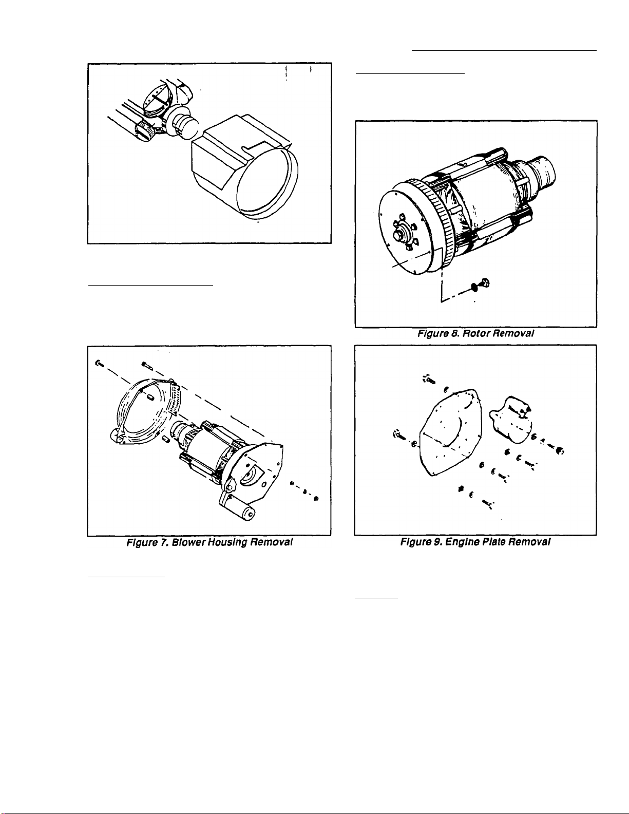
BLOWER HOUSING REMOVAL:
Remove the capscrews that retain the Blower Hous
ing to the Engine Plate, along with flat washers, lock
washers and hex nuts. Note positions of longer and
shorter screws, for reassembly.
SECTION 1.4- MAJOR COMPONENTS
(UNITS WITH 10 INCH STATOR)
1
ENGINE PLATE REMOVAL:
Remove starter retaining bolts and remove starter.
Remove bolts that retain the engine plate. Remove the
engine plate.
ROTOR REMOVAL;
Remove capscrews and washers that retain the Cou
pling Plate to the Ring Gear. Remove Rotor, Cooling
Fan, Drive Hub and Coupling Plate as a unit.
If desired, the Cooling Fan, Drive Hub and Coupling
Plate may be removed from the Rotor.
Components Inspection and Testing
GENERAL;
Follovving disassembly, generator components
should be cleaned, dryed and inspected or tested.
Never reassemble a generator with defective or
damaged parts. Store parts In a dean, dry area.
PAGE 1.4-3
Page 22

SECTION 1.4- MAJOR COMPONENTS
(UNITS WITH 10 INCH STATOR)
Components Inspection
REAR BEARING COVER AND GASKET:
Clean the Beeuing Cover in a suitable non-flammable
commercial cleaner. Blow dry with compressed air.
Inspect the Cover for obvious damage, clogged air slots,
etc. Replace, if necessary. Inspect gasket, replace if
damaged or defective.
REAR BEARING CARRIER;
The Rear Bearing Carrier is an aluminum casting.
Clean the casting and blow dry with air. Inspect carefully
for cracks, damage. An insert is pressed into the Bear
ing Carrier center bore, to accommodate the Rotor
bearing. Use an inside micrometer to check the inside
diameter of the insert. Replace the Bearing Carrier if the
insert inside diameter is not within the following:
PARTI
THE REVOLVING FIELD AC GENERATOR
J
and Testing (Continued)
the Rotor with dry, heated airfor several hours. DO NOT
EXCEED 185* F. (85* C.). if Insulation resistance is still
low after drying, replace the Rotor Assembly.
FAN AND RING GEAR ASSEMBLY:
The FAN, DRIVE HUB, COUPLING PLATE and
RING GEAR are assembled and balanced as a unit.
Clean and inspect parts, replace the entire assembly if
necessary.
BRUSH HOLDER AND BRUSHES:
Inspect both brush holders and both sets of brushes.
Look for cracks, excessive wear, cracks, chipping, etc.
Replace any damaged brush holder. Brushes should be
replaced as a complete set
2.834-2.836 inches (71.996-72.012mm)
STATOR ASSEMBLY:
Clean the stator can exterior surfaces with a soft
brush or cloth. Use clean, dry low pressure air (25 psi
maximum) to clean the stator. Use an ohmmeter to test
the resistance of Stator AC power and excitation wind
ings. Use an insulation resistance tester (megohmmeter
or Hi-Pot tester) to check condition of Stator insulation
(see Section 1.8). If Stator insulation fails the test, the
Stator may be dried by blowing warm, dry air across it
for several hours. DO NOT EXCEED 185* F. (85* C.). If
insulation resistance is still low after drying, replace the
Stator.
BLOWER HOUSING:
Clean with a commercial solvent that is suitable for
use with aluminum. Inspect the Housing carefully for
cracks, damage, etc. Replace, if necessary.
ROTOR ASSEMBLY:
Clean with dry, low pressure air (25 psi maximum).
Test Rotor winding resistance with an ohmmeter. Check
Rotor bearing for binding, seizing, roughness. If the
bearing is defective, replace the Rotor assembly. In
spect the keyway in the tapered shaft for wear, damage.
If slip rings are dull or tarnished, clean with fine
sandpaper. Use an insulation resistance tester
(megohmmeter or Hi-Pot tester) to test for insulation
breakdown (see Section 1.8). If resistance is low, dry
Inspect brush leads No. 1 and 4. Replace any
damaged or defective brush lead.
Generator Reassembly
Reassemble the generator in the reverse order of
disassembly. The reassembly process requires a great
deal of care. All components must be properly aligned
and retained. Tighten all fasteners to the recommended
torque values. Following reassembly, perform an opera
tional test of the unit.
Components In Generator Control Panel
INTRODUCTION:
The following AC generator components are
mounted on or housed in the generator control panel:
□ Voltage Regulator Assembly.
□ An AC Circuit Breaker (CB1 and CB2).
□ Exdtation Circuit Breaker (CB4).
□ A field boost circuit.
In addition to the above AC generator components
housed in the control panel, aTHERMAL PROTECTOR
is physicaliy imbedded in the wire windings of the Stator
Assembly.
Other components are housed in the control panel,
as well. However, these components are part of the
engine's DC control system and will be discussed in
PART 5, "ENGINE ELECTRICAL SYSTEM".
PAGE 1.4-4
Page 23
PARTI
THE REVOLVING FIELD AC GENERATOR
Components in Generator Control Panel (Continued)
SECTION 1.4- MAJOR COMPONENTS
1
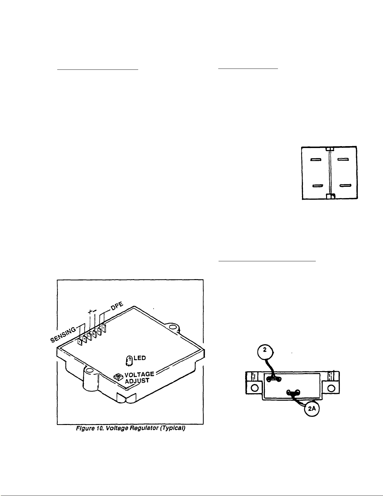
THE AC VOLTAGE REGULATOR:
The VoKage Regulator used on units with 10 inch
stator is shown In Figure 10. The Regulator has a single
red lamp (LED) which will remain on during operation
as long as stator AC power winding "sensing* voitage is
avaiiabie. Three sets of leads connect to the Regulator
terminals as follows:
D Unregulated AC output from the stator excitation
winding connect to the two terminals indicated by
"DPE*.
□ Sensing (actual) voltage signals from the stator
AC power windings are delivered to the
Regulator terminals indicated by "SEN".
□ Rectified and regulated (DC) current Is delivered
to the Rotor winding from Regulator terminals
Indicated by a"+" and
The Regulator provides over-voltage protection. On
loss of "sensing", the Regulator will shut down and
regulated excitation current to the Rotor will terminate.
A single adjustment potentiometer permits the gener
ator's AC output voltage to be adjusted. Perform this
adjustment with the engine running at no-load and with
AC frequency at 62 Hertz (1860 rpm). At 62 Hertz, set
the line-to-neutral AC output voltage to 124 volts AC; or
the line-to-line AC output voltage to 248 volts AC.
AC CIRCUIT BREAKERS:
Two AC output circuit breakers (CB1 and CB2) are
provided, one for each line of the 240 volts AC output
circuit. The trip rating of these breakers depends on the
rated maximum amperage capacity of the generator.
Units rated at 8000 watts (8.0 kW) are equipped with AC
breakers rated at 35 amperes.
Schematic
Pictorial
11
SEE FIGURES 4 & 5 ON
PAGE 1.5-2 FOR WIRING
CONNECTIONS
Figure 11. AC Output Circuit Breakers
EXCITATION CIRCUIT BREAKER (CB4):
An AC circuit breaker, rated 5 amperes, is electrically
connected in series with Wires No. 2 and 2A betwen the
stator excitation winding and the Voltage Regulator. If
the breaker should trip (open) due to an overload, loss
of excitation current to the Rotor will occur. Generator
AC output voltage will then decrease to a value that is
commensurate with Rotor residual magnetism (about 2
to 7% of the unit's rated voltage). The breaker is self
resetting and cannot be reset manually.
Figure 12. Excitation Circuit Breaker
PAGE 1.4-5
Page 24
SECTION 1.4- MAJOR COMPONENTS
(UNITS WITH 10 INCH STATOR)
1
Components In Generator Control Panel (Continued)
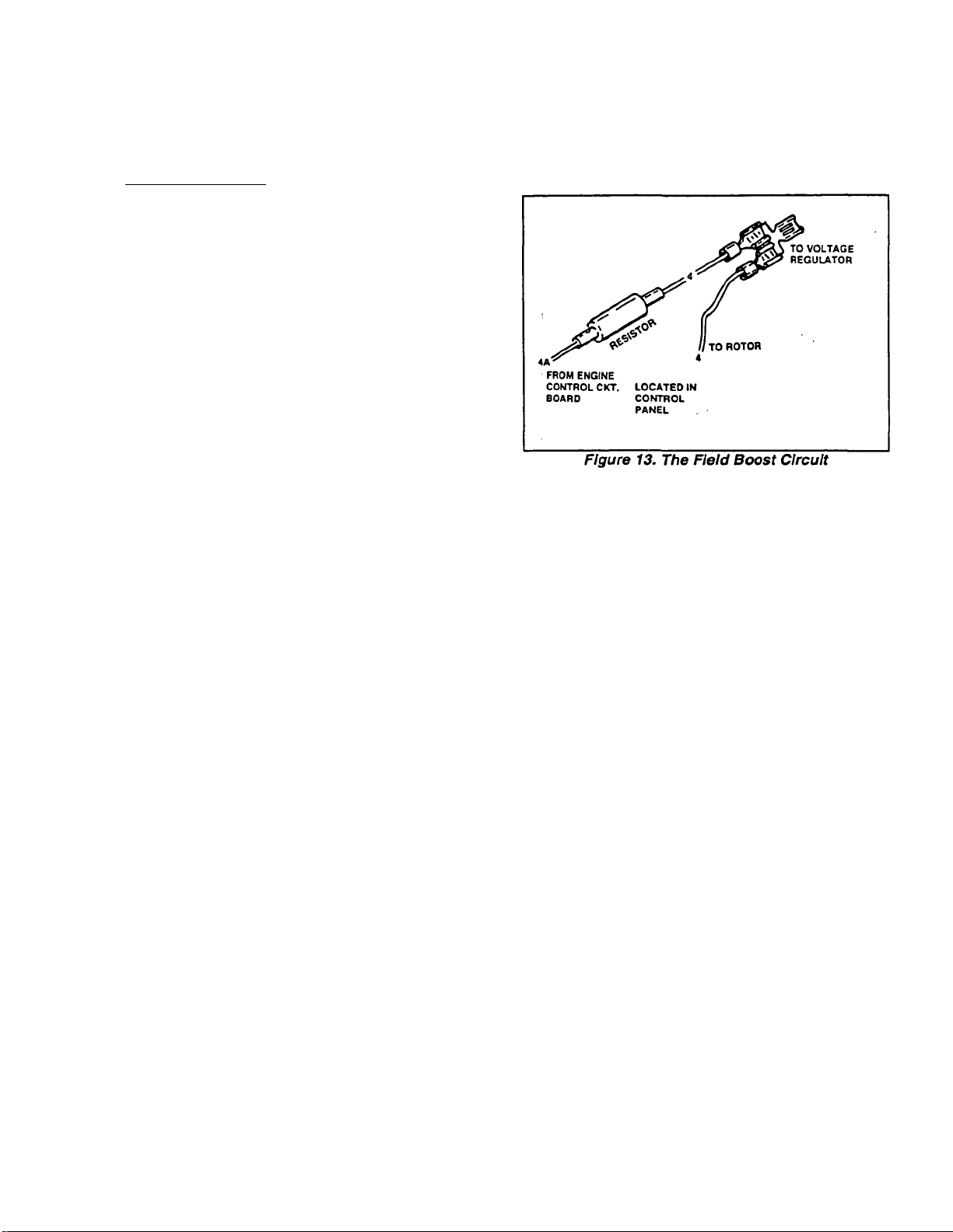
FIELD BOOST CIRCUIT
During engine cranking, an engine controi circuit
board deiivers battery voltage to the Rotor windings.
This "Field Boost" current is delivered to the Rotor via
Wire 4A, a field boost resistor, and Wire 4. The Field
Boost feature provides the following benefits:
□ In effect, field boost current "flashes the field" on
every engine startup. Thus, if Rotor residual magne
tism was lost for any reason, it would be restored by
the act of "flashing the field" during cranking.
□ Approximately 4-8 volts AC output from the stator
excitation winding is needed to turn the voltage reg
ulator on. Reid boost current builds Rotor magnetism
early which, in turn, develops voltage early during
startup. The result of field boost is an early "pickup"
voltage in the stator windings.
THERMAL PROTECTOR:
Refer to " THERMAL PROTECTOR' on Page 1.3-7.
PARTI
THE REVOLVING FIELD AC GENERATOR
PAGE 1.4-6
Page 25
PARTI
THE REVOLVING FIELD AC GENERATOR
Section 1.5
INTRODUCTION TO TROUBLESHOOTING
DANGER: GENERATORS PRODUCE EXTREMELY
HIGH AND DANGEROUS VOLTAGES. CONTACT
WITH LIVE WIRES OR TERMINALS WILL RESULT
IN HAZARDOUS AND POSSIBLY FATAL ELECTRI-
<CAL SHOCK. ONLY PERSONNEL WHO HAVE
BEEN TRAINED IN THE SERVICING AND REPAIR
OF RV GENERATORS SHOULD ATTEMPT TO
TROUBLESHOOT, TEST OR REPAIR THESE GEN
ERATORS.
Tools and Test Equipment
An RV generator service technician shouid have a
weii stocked tool box that is fiiied with a good seiection
of common hand tools. The tool box should contain
combination wrenches and socket wrenches in both
standard and metric sizes. Also, a good nut driver set is
recommended.
SECTION 1.5
INTRODUCTION TO TROUBLESHOOTING
1
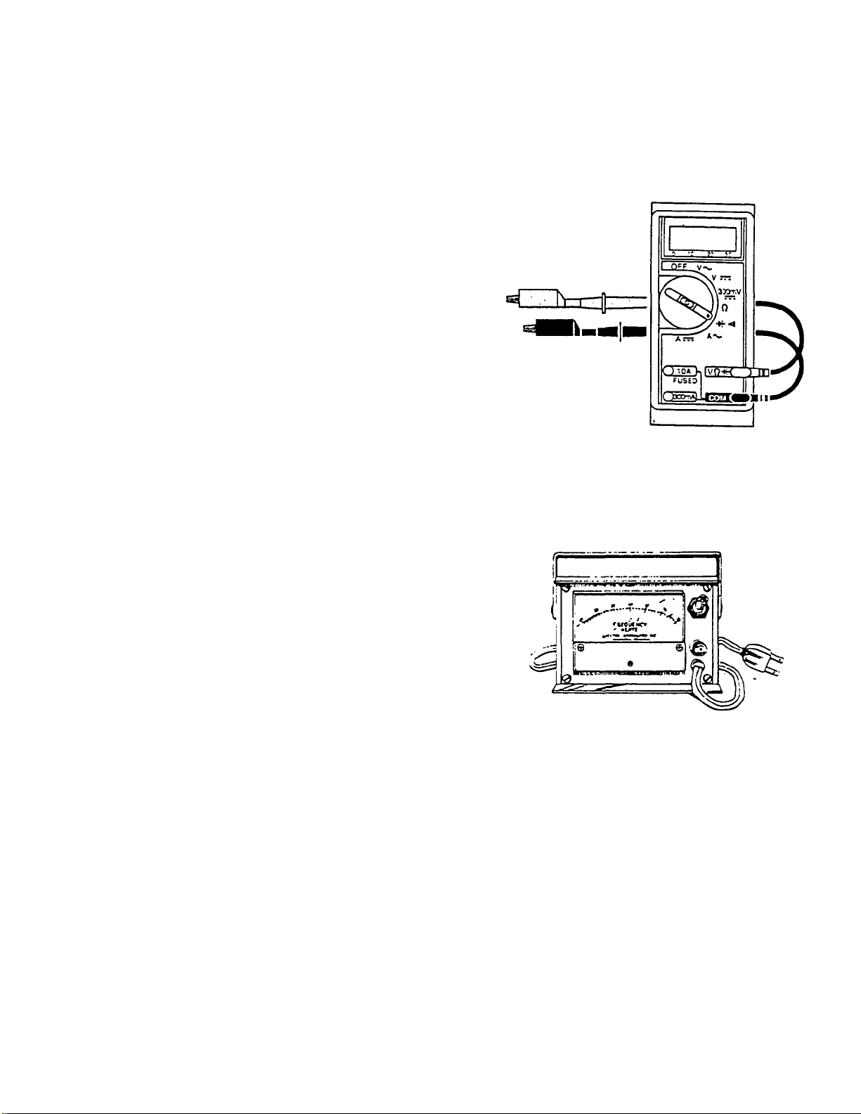
Figure 1. Typical Volt-Ohm-Mllllamm eter (VOM)
The following test equipment is recommended:
□ An accurate volt-ohm-milliammeter (VOM),
preferably a precise digital type.
□ A good AC frequency meter.
D An insulation resistance tester (megohmmeter or
Hi-Pot tester).
O A load bank or some means of applying a known
electrical load to the generator.
Volt-Ohm>Milllammeter (VOM)
If desired, three separate meters may be used, i.e., a
voltmeter, ohmmeter and ammeter. Recommended is
an accurate digital type VOM having a ’Diode Check'
mode.
The service technician must be familiar with his VOM
and must know how to use it. He must also be familiar
with generator electrical circuits and must be able to
read electrical vriring diagrams and schematics.
Frequency Meter
The generator’s AC output frequency must be known
if engine governed speed Is to be property adjusted. See
"ROTOR ROTATIONAL SPEED’ in this section.
Figure 2. One Kind of AC Frequency Meter
Testing Insulation Resistance
Insulation resistance Is a measurement of the In
tegrity of the Insulating materials that separate the
electrical windings from the generator’s steel core. This
resistance can degrade over time due to contaminants
such as dust, dirt, grease and especially moisture.
Information on Insulation resistance test can be found
in Section 1.8, "INSULATION RESISTANCE TESTS'.
PAGE 1.5-1
Page 26
SECTION 1.5
INTRODUCTION TO TROUBLESHOOTING
Rotor Rotational Speed
"NP" series generators are equipped with a 4-pole
Rotor. That is, the Rotor has two south magnetic poles
and two north magnetic poles. A 4-pole Rotor must be
operated at 1800 rpm to obtain a 60 Hertz AC output
frequency. The following formulas apply when calculat
ing frequency, rpm and number of Rotor poles:
Hertz = RPM X No. of Rotor Poles
2x 60
RPM = 2 X 60 X Hertz
No. of Rotor Poles
PART 1
THE REVOLVING FIELD AC GENERATOR
L
A second alternative Is to connect the wiring to supply
120 volts AC only (Figure 5). When this connectior
method Is used, a jumper wire must be connected
between the two main circuit breakers (CB1 and CB2),
as shown.
No. of =
Poles
2 X 60 X Hertz
RPM
Voltage and Frequency
The generator's solid state Voltage Regulator will
maintain an AC output voltage that is at a fixed ratio to
frequency. For example, at a frequency of 60 Hertz, AC
output voltage will be maintained at about 120/240 volts
(plus or minus 2%). Should frequency drop to 30 Hertz,
voltage will decrease proportionally to about 60/120
volts.
For generators rated 120/240 volts, the engine gover
nor should be set to maintain a NO-LOAD frequency of
about 60.5-63.5 Hertz. The Voltage Regulator should
then be set to maintain a voltage of about 121-127 volts
(line-to-neutral); or 242-254 volts (line-to-line).
Stator AC Connection Systems
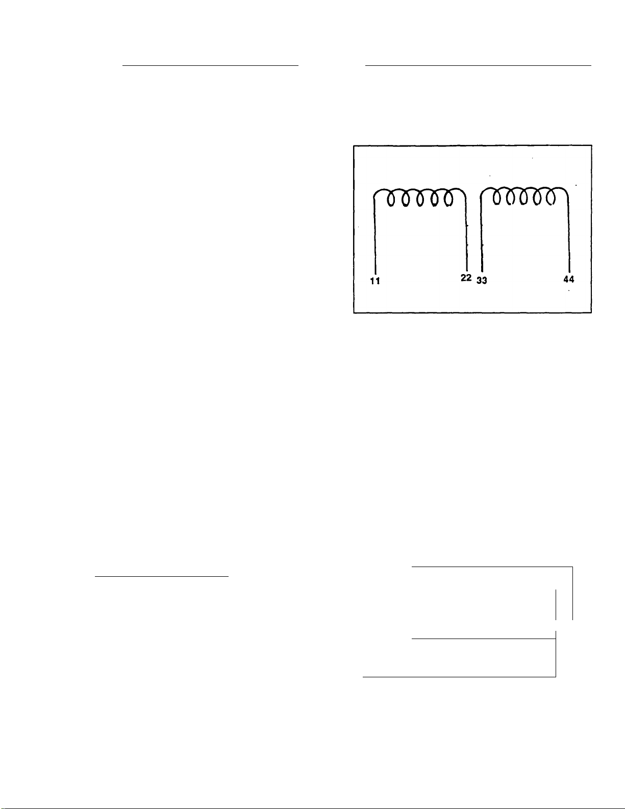
1-PHASE, DUAL WINDING TYPE:
Some NP/IM series generators have dual AC
power windings (Figure 3). Each winding supplies a
120 volts AC output. When the two windings are con
nected in series (Figure 4), a 240 volts AC output
results.
When installed, the unit may have ben connected to
supply a dual voltage output (120 and/or 240 volts). This
is shown In Figure 4. A 3-wire connection system Is
used. Stator leads No. 11 and 44 form the two "hot"
leads; the Junction of stator leads 22 and 33 form the
"Neutral" lead. Notice the "Neutral" line is grounded.
Figure 3. The Dual Stator AC Power Windings
nnrowi fWtrCPi
,, 22 33 44
)CB. ‘f CBzS
T2
-120 V.----------------^
T1
(RED)
Figure 4. Connected for Dual Voltage AC Output
11
(WHnE)
■ 24-3V.
22 33 1
------------------------------------
L 1
K—
T
-------------
T3
(BLACK)
I«
-----------------
120V.
---------------------------------
1
1
T1
(RED)
^
-----------------
Figure 5. Connected for 120 Volts AC Output
■ 120V.-
120 V.
---------
T3
(BLACK)
44
------
T2
-------
-------
(WHITE)
P
»
/
r
PAGE 1.5-2
Page 27
PART1 I SECTION 1.5
THE REVOLVING FIELD AC GENERATOR ■ INTRODUCTION TO TROUBLESHOOTING
Stator AC Connection Systems (Continued)
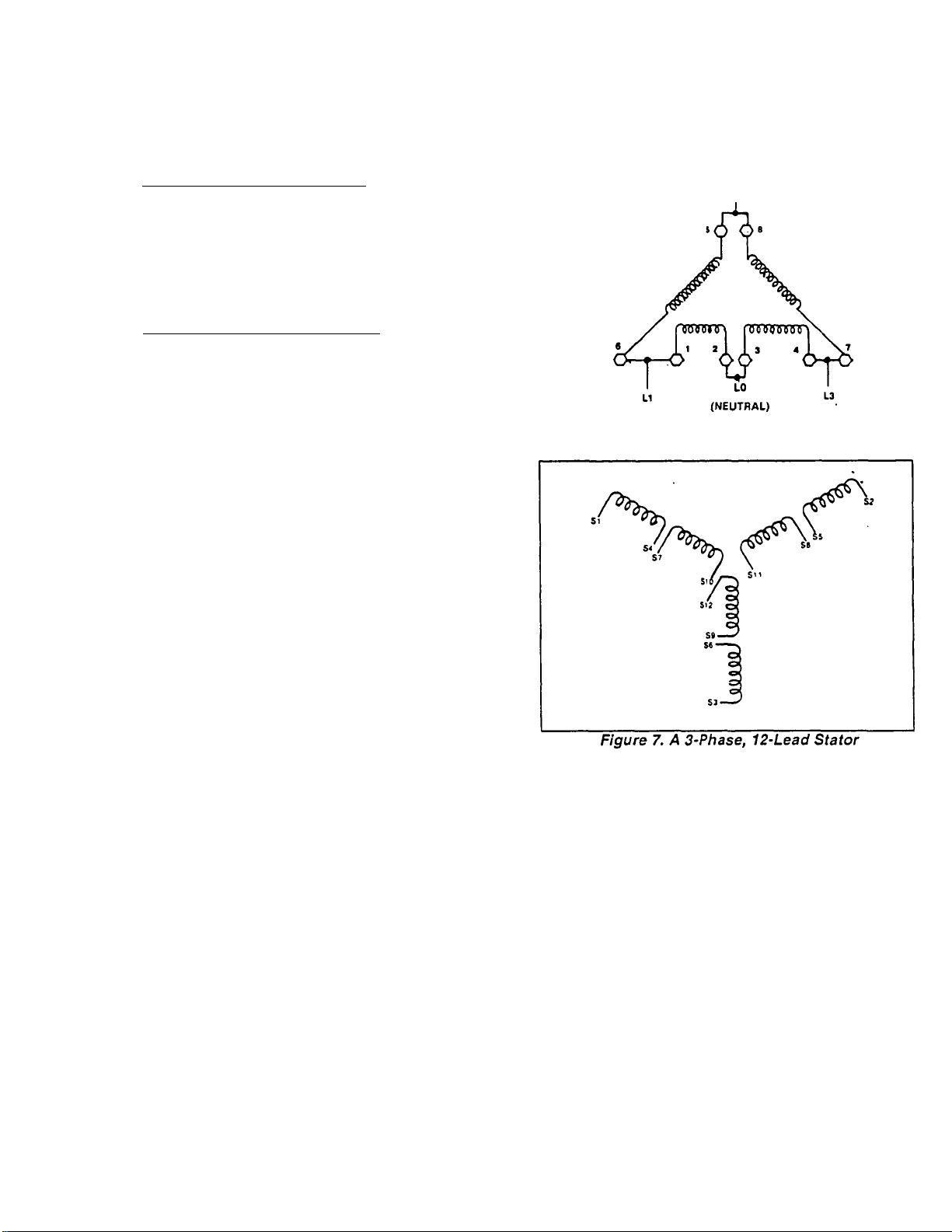
3-PHASE DELTA STATOR WINDING:
Some units may be equipped with a 3-phase delta
type stator winding, shown in Figure 6. Phase rotation
is L1-L2-L3. The ^Neutral* line is designated as "LO’.
Generator Model No. 9422 uses this type of stator to
deliver 120 volts AC (line-to-neutral); or 240 volts AC
(line-to-line).
3-PHASE. WYE-CONNECTED SYSTEM:
Figure 7 shows a 3-phase Wye-Type stator which
has 12 AC output leads that are reconnectable to
supply several voltages. Generator Model 9318 uses
this type of statorto supply 220/380 volts AC at 50 Hertz
(i.e., 220 volts AC line-to-neutral; 380 volts AC line-toline).
Figure 6. A 3-Phase Delta Stator
PAGE 1.5-3
Page 28

SECTION 1.5
INTRODUCTION TO TROUBLESHOOTING
PARTI
ITHE REVOLVING FIELD AC GENERATOR
PAGE 1.5-4
Page 29
PARTI
THE REVOLVING FIELD AC GENERATOR
SECTION 1.6- TROUBLESHOOTING
(UNITS WITH 15 INCH STATOR)
1
Section 1.6
TROUBLESHOOTING
(UNITS WITH 15 INCH STATOR)
Introduction
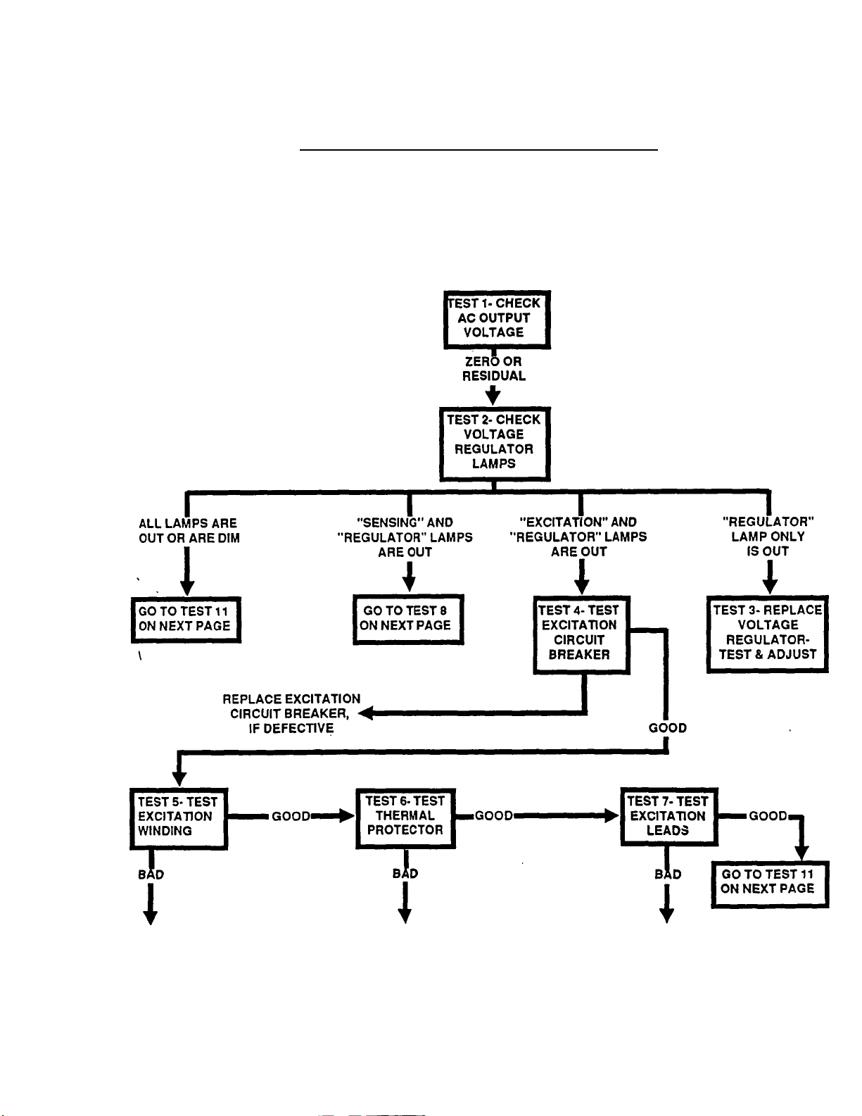
The 'Troubleshooting Flow Charts' that follow have been carefully formulated to help the technician find the
cause of problems quickly and easily. Use the Charts as a guide In troubleshooting RV generator problems, to help
avoid the unnecessary labor and expense of replacing parts needlessly. Test numbers in the Charts correspond to
the numbered tests In the 'DETAILED INSTRUCTIONS' that follow the Flow Charts.
Problem 1- Generator Produces Zero or Residual Voltage at No-Load
REPLACE
STATOR
BYPASS
THERMAL PROTECTOR
RECONNECT,
REPAIR OR REPLACE
PAGE 1.6-1
/•.'3c
Page 30

SECTION 1.6- TROUBLESHOOTING
(UNITS WITH 15 INCH STATOR)
Problem 1 - Generator Produces Zero or Residual Voltage at No-Load (Continued)
PART 1
THE REVOLVING FIELD AC GENERATOR
1
TEST 8- CHECK
SENSING LEADS
BAD
AT/M3
i
RECONNECT, REPAIR OR
REPLACE BAD LEADS AS
NECESSARY
TEST 11-TEST
ROTOR
WINDINGS
BAD
I
REPLACE ROTOR
---------
O.K._^ BRUSHES AND
r\ 1/ w
TEST 9-TEST
TRANSFORMER
REPLACE BAD
TRANSFORMER
TEST 12- CHECK
REPLACE BRUSHES
OR CLEAN SLIP RINGS,
AS NECESSARY
CCKICIAI/^
BAD
J
SLIP RINGS
I
I
--
rsr\r\r\^
«O.K.^
TEST 10- TEST
CTATnn An
POWER
WtNniNnft
BAD
\
REPLACE
STATOR
ASSEMBLY
TEST 13- CHECK
WIRES NO.
1 AND 4
T
BAD
I
RECONNECT,
REPAIR OR REPLACE
BADWIRE(S)
TEST 14- TEST
FIELD
BOOST
BAD
»
REPAIR BAD
WIRE(S) OR
REPLACE BAD
PART(S)
Problem 2- Generator Produces Low Voltage and Frequency at No-Load
(Greater than Residual Voltage)
TESTIS- CHECK
VOLTAGE AND
FREQUENCY
FREQUENCY GOOD,
VOLTAGE IS LOW
NOTE: A shorted stator winding can cause rpm, frequency and voltage to droop excessively In the same
manner as when the unit’s wattage/amperage capacity Is exceeded.
BOTH
__ AREbh^
LOW
TEST 17-CHECK
AND ADJUST
VOLTAGE
REGULATOR
TEST 16-ADJUST
ENGINE
GOVERNOR
LOW VOLTAGE
, AND/OR LOW FREQUENCY!
CONDITION
IS NOT CORRECTED
FREQUENCY AND
I VOLTAGE GOOD-
AFTER ADJUSTMENT
^1 STOP TESTS
GOTO
PROBLEM 1
PAGE 1.6-2
Page 31

PARTI
THE REVOLVING FIELD AC GENERATOR
Problem 3- Generator Produces High Voltage at No-Load
SECTION 1.6- TROUBLESHOOTING
(UNITS WITH 15 INCH STATOR)
1
TESTIS- CHECK BOTH
VULi AuiC MHil/
FREQUENCY
FREQUENCY GOOD,
VOLTAGE IS HIGH
TEST 17- CHECK
L
Problem 4- Voltage and Frequency Drop Low When Electrical Loads are Applied
TESTIS- CHECK
FOR OVERLOAD
CONDITION
1 la
HIGH
AND ADJUST
VOLTAGE
REGULATOR
TEST 16-ADJUST
GOVERNOR
UNIT IS NOT
HIGH VOLTAGE
CONDITION w
CORRECTED
W
O.K.
ADJUSTMENT
VOLTAGE REGULATOR,
TEST 16-ADJUST
ENGINE
GOVERNOR
TESTS- REPLACE
TEST AND ADJUST
.. NOWHii|
I O.K. NOW-
UNIT IS OVERLOADED
REDUCE LOAD TO UNIT’S
RATED WATTAGeAMPERAGE
CAPACITY
VOLTAGE/FREQUENCY
STILL DROP LOW
WHEN LOADS ARE
APPLIED
i
TEST 19- CHECK
CMr^lMC D/MAICn
AND CONDITION
r
I^STOPTIST^
REPAIR
NEEDED
PAGE 1.6-3
Page 32

SECTION 1.6- TROUBLESHOOTING
(UNITS WITH 15 INCH STATOR)
1
Detailed Instructions
INTRODUCTION:
The following diagnostic test instructions are num
bered to correspond with the numbered tests in the
troubleshooting 'Row Charts’ on Pages 1.6-1 through
1.6-3. Read the instructions carefully.
PARTI
THE REVOLVING FIELD AC GENERATOR
Results: Analyze the results of the AC output voltage
test as follows:
1. If the reading is zero volts or residual volts, perform
tests as indicated under Problem 1 of the Flow Charts.
TEST 1- CHECK AC OUTPUT VOLTAGE:
Discussion; In order to identify the specific probiem,
it is necessary to measure the generator’s AC output
voltage. Some Installations may Include an optional AC
meter package. Even when this is the case, it is a good
idea to verify the AC voltage with an external meter. In
some cases, the AC meter(s) on the optional package
may be reading incorrectly.
Remember, some installed units may be connected
for dual voltage AC output (120 and/or 240 volts). Some
units may be connected for 120 volts AC output only.
Also see "STATOR AC CONNECTION SYSTEM" on
Page 1.5-2.
Procedure; An AC voltmeter or a volt-ohm-milliammeter (VOM) may be used to measure voltage. If the
unit is installed in a vehicle, the meter may be connected
to a convenient receptacle. For uninstalled units, con
nect the VOM across Wires No. T1 (red) and T3 (black)
to obtain a line-to-line voltage reading (240 volts). For a
line-to-neutral reading (120 volts), connect the VOM
across line T1 (red) and T2 (white); or across line T3
(black) and T2 (white). With the unit runing at no-load,
read the AC voltage. Voltage should be 121-127 volts
(line-to-neutral): or 242-254 volts (line-to-line).
NOTE: "Residual" voltage Is that voltage produced
as a result of Rotor residual magnetism only. It Is
equal to approximately 2 to 7percent of the unit’s
rated voltage. For units rated 120/240 volts, residual
voltage will be approximately 2.4-0.4 volts (llne-to-
neutral); or 4.8-16.8 volts (llne-to-llne).
2. If the voltage is low, but greater than residual, go to
Problem 2 of the Flow Charts.
3. If AC output voltage is high, go to Problem 3 of the
Flow Charts.
4. If AC output voltage Is normal at no-load, but drops
excessively when electrical loads are applied, go to
Problem 4 of the Flow Charts.
Test 2- Check Voltage Regulator Lamps
Discussion: Refer to 'AC VOLTAGE REGULATOR'
on Pages 1.3-5 and 1.3-6.
Procedure: Gain access to the AC Voltage Regulator
in the control panel. With the generator running at
no-load, observe the condition of the Regulator lamps
(LED’s).
nrSMiTi nnrotRPi
1 22 33 44
CB1 CB2 )
)
Qy )—1
T2
(WHITE)
-120V
___________
T1
SHOWN CONNECTED FOR DUAL (BLACK)
VOLTAGE AC OUTPUT. FOR 120
VOLTS OUTPUT, SEE FIGURE 5
ON PAGE 1.5-2.
Figure 1. Stator AC Output Leads
NOTE: Line T1 (red) and T3 (black) are the two "hot''
lines. Line T2 (white) Is the "Neutral" line.
^ 4
• 240V. •
---------
120V.
■ K
T3
PAGE 1.6-4
The Voltage Regulator lamps are normally ON
during engine-generator operation. It is suggested that
■ AC VOLTAGE REGULATOR' on Pages 1.3-5 and
1.3-6 be read carefully. The REGULATOR lamp will go
out if (a) a Regulator fault exists, or (b) if the Regulator
has shut down due to occurence of one or more Reg
ulator shutdown conditions. The EXCITATION lamp
will go out on loss of stator excitation winding output to
the Regulator. The SENSING lamp will go out on loss
of sensing input to the Regulator.
Resülts:
1. if ail lamps are out, go to Test 11.
2. If the 'Sensing' lamp is out, go to Test 8.
3. If the ’Excitation* lamp is out, go to Test 4.
4. If the 'Regulator* lamp Is out, go to Test 3.
Page 33

PARTI
THE REVOLVING FIELD AC GENERATOR
Detailed Instructions
TEST 3- REPLACE REGULATOR, TEST/ADJUST;
Discussion: The Voltage Regulator lamps (LED’s)
are normally ON. If the 'Regulator* lamp is OUT, the
Voltage Regulator has shut down or has failed. A
'Regulator lamp ON condition indicates the
Regulator’s SCR’s (silicone controlled rectifiers) are
firing.
"U
---
" ^ .
----------------------------------
V
«
Figure 2. The Part No. 67680 Voltage Regulator
Procedure: Unplug the voltage regulator connec
tor plug. Remove the screws, flatwashers and
lockwasners that retain the regulator to the control
panel. Remove the regulator. Install the new regulator,
test and adjust as outlined in Section 1.9, ‘OPERA
TIONAL TESTS AND ADJUSTMENTS'.
NOTE: Before attempting to adjust the voltage reg
ulator, the engine governor must be properly ad
justed to maintain a no-load frequency of 60.5-63.5
Hertz (1815-1905 rpm). Correct no-load AC output
voltage setting Is 121-127 volts AC (llne-to-neutral),
or 242-257 volts AC (llne-to-llne).
Results: If problem is corrected, discontinue tests.
If problem still exists, continue troubleshooting as indi
cated in the 'Flow Charts".
TEST 4- TEST EXCITATION CIRCUIT BREAKER:
Discussion: See Figure 3. The excitation circuit
breaker is electrically connected in series with the
stator excitation winding AC output to the voltage reg
ulator. It is physically mounted in the control panel
interior. Should the breaker fail open, loss of excitation
winding output to the regulator will occur. Without exci
tation current, the regulator will shut down and gener
ator AC output will drop to a voltage commensurate with
Rotor residual magnetism. The breaker cannot be reset
manuaily (it is normally self-resetting). If it has failed
open, it must be replaced.
VOCTAQE ADJUST
UNOERFREOUENCY
— .. - 1 ^
OAIN
STABIUmr
ADJUST
REGULATOR
SENSING
EXCITATION
In^
Ine®
r«®
®
SECTION 1.6- TROUBLESHOOTING
(UNITS WITH 15 INCH STATOR)
1
from excitation grinding
to voltage regulator
Figure 3. Excitation Circuit Breaker
Procedure: To prevent interaction, disconnect
Wires No. 2 and 162 from the circuit breaker terminals.
Set a VOM to its "Rxl' scale and zero the meter.
Connect thè VOM test probes across the two circuit
breaker terminals. The meter should read "continuity*.
Resuits: •
1. If the meter displays any reading o(;her than "conti
nuity", replace the excitation circuit breaker.
2. If the VOM reads "continuity", go on to Test 5.
NOTE: When reading resistance across the circuit
breaker contacts, a very small resistance reading
Is acceptable. An oxide film can build up on circuit
breaker contact surfaces, causing the small resis
tance.
TEST 5- TEST STATOR EXCITATION WINDING:
Discussion: An open circuit in the stator excitation
(OPE) winding will result in loss of excitation current to
the Voltage Regulator. An excitation winding AC output
of approximately 4-8 volts AC is required to turn the
Voltage Regulator on. Thus, on loss of excitation wind
ing output, the Regulator will shut down and regulated
excitation current to the Rotor will terminate. Generator
AC ou^ut voltage will then drop to a value commensu
rate with Rotor residual magnetism plus field boost
current (about one-half normal no-load AC output volt
age). An open winding will be Indicated by a VOM
reading of 'infinity* or a very high resistance reading. A
shorted excitation winding will be Indicated by a veiy
low resistance reading. In the following 'Procedure*^,
the excitation winding will also be testedfor a grounded
condition.
Procedure: See Figure 4, next page. In the control
panel, locate unattached Wire No. 5. This is the thermal
protector bypass lead. Remove the wire nut from end
of Wire No. 5. Also locate Wire No. 6, connected to Pin
6 of the voltage regulator plug. On some units, a barrel
lug may be used to connect Wire No. 6 between the
voltage regulator and the stator excitation winding. Test
the stator excitation winding for an open, shorted or
grounded condition as follows:
PAGE 1.6-5
Page 34

SECTION 1.6- TROUBLESHOOTING
(UNITS WITH 15 INCH STATOR)
Detailed Instructions (Continued)
PART 1
THE REVOLVING FIELD AC GENERATOR
1
1. Set a VOM to Its ’Rxl ’ scale eind zero the meter.
2. Connect the VOM test probes across Wire No. 5 and
Pin 6 of the Voltage Regulator. The meter should read
the resistance of the stator excitation winding (about
0. 53.ohm).
3. Now, set the VOM to a very high resistance scale
such as ’Rx10,000" or "Rx1 K". Again, zero the meter.
a. Connect one VOM test lead to bypass Wire No. 5,
the other to a clean frame ground on the stator. The
meter should Indicate "infinity".
b. Any reading other than "infinity" indicates a shorted
condition and the stator should be replaced.
4. With the VOM still set to a high resistance scale,
connect one VOM test probe to stator Wire No. 5, the
other to stator ac output Wire No. 11 or 22. "Infinity"
should be Indicated.
5. Connect the VOM test probes across Wire No. 5 and
stator AC output Wire No. 33. "Infinity" should be indi
cated.
Results:
1. If the stator excitation winding fails any part of the test,
replace the stator assembly.
2. If the stator excitation winding checks good, go on to
Test 6.
Results:
1. If normal excitation winding resistance was indi
cated in Test 5, but "infinity" was Indicated in Test 6, the
thërmal protector is open and must be bypassed.
2. If normal excitation winding resistance was indi
cated in both Tests 5 and 6, the thermal protector is
good. Go on to Test 7.
TEST 7- TEST EXCITATION LEADS:
Discussion: An open or shorted condition in the
stator excitation winding's output leads to the Regulator
will cause complete or partial loss of the unregulated
excitation current to the Regulator.
Procedure: Inspect Wires No. 2,6 and 162, between
the stator and the Voltage Regulator. Make sure they
are properly connected and undamaged. Use a VOM to
test the wires tor "continuity".
Results:
1. Reconnect, repair or replace any damaged, discon
nected or shorted wire(s). /
2. If all excitation leads are good, go to Test 11.
Figure 4. Excitation Winding Test Points
TEST 6- TEST THERMAL PROTECTOR:
Discussion: You may wish to review the information
on the thermal protector. See Page 1.3-7.
Procedure: Set a VOM to its "Rxl" scale and zero
the meter. Connect the VOM test probes across stator
wires No. 2 and 6. See Table 1, Page 6.1-1 for nominal
resistances.
TEST 8- CHECK REGULATOR SENSING LEADS:
Discussion: An open or shorted condition in the
sensing leads to the Voltage Regulator will result in loss
of sensing (actual voltage) signals to the Voltage Reg
ulator. The Regulator’s "Sensing" lamp will then go out.
Procedure: Carefully inspect Wires SI 5 and SI6,
between the Regulator and the sensing transformer.
Also inspect Wires No. 11 and 22, between the sensing
transformer and the stator. Use a VOM to test all wires
for an open or shorted condition.
Results:
1. Reconnect, repair or replace any disconnected,
damaged or defective wire(s).
2. If the sensing leads are good, go on to Test 9.
TEST 9- TEST SENSING TRANSFORMER:
Discussion: The Part No. 67680 Voltage Regulator
requires a 240 volts AC sensing signal to operate
properly. You may wish to review the information on the
sensing transfonmer on Page 1.3-6.
PAGE 1.6-6
Page 35

PARTI
THE REVOLVING FIELD AC GENERATOR
Detailed Instructions (Continued)
SECTION 1.6- TROUBLESHOOTING
(UNITS WITH 15 INCH STATOR)
1
Procedure: Gain access to the sensing trans
former, inside the control panel. Use a volt-ohm-milli-
ammeter (VOM) to test the sensing transformer as
follows:
1. Disconnect Wires No. 11 and 22 from the
transformer’s PRIMARY terminals, to prevent interac
tion.
2. Connect the VOM test leads across the two PRI
MARY (120 volts) terminals. Resistance of this winding
should be approximately 120 ohms (plus or minus 2%).
3. Disconnect Wires No. SI5 and SI 6 from the trans
former SECONDARY (240 volts) terminals, to prevent
interaction.
4. Connect the VOM test leads across the two SEC
ONDARY (240 volts) terminals. Resistance should be
approximately 950 ohms (plus or minus 2%).
Results:
1. If the transformer fails the test, it should be replaced.
2. If the transformer checks good, go on to Test 10.
PRIMARY
120 VAC
[qooopI
oaoWflÒSbì
2. Set a VOM to its ■ Rxl’’ scale and zero the meter.
3. Test the windings as follows:
a. Connect the meter test leads across Wires No. 11
and 22. Resistance reading should be approximately
as listed in chart in Part 6.
b. Connect the meter test leads across Wires No. 33
and 44. Resistance reading should be approximately
as listed in chart in Part 6.
c. Set the VOM to a very high resistance scale, such
as 'Rxl 0,000" or "RxlK". Then, zero the meter.
d. Make sure none of the stator leads are touching
the generator or each other at any point. Connect
one VOM test probe to Wire No. 11, the other test
probe to Wire No. 33. The VOM should read "Infinity“.
Any reading other than "infinity" indicates a short
between the stator windings.
e. Connect one VOM test probe to Wire No. 11, the
other to a clean frame ground on the stator. VOM
should read "infinity".
f. Connect one VOM test probe to Wire No. 33, the
other to a clean frame ground. Reading should be
"infinity".
nmnrin
rWiRRTi
■ 6
SECONDARY
20 VAC
Figure 5. The Sensing Transformer
TEST 10- TEST STATOR AC POWER WINDINGS:
Discussion: An open condition in eitherof the dual
stator AC power windings will result In loss of AC output
from the affected winding. A shorted condition in those
windings will cause a reduction in AC voltage that is
commensurate with the number of shorted turns. A
shorted condition can also impose such a heavy load
on the engine that engine speed and AC frequency will
also drop sharply. This test will check the stator AC
power windings for (a) an open condition, (b) a shorted
condition, and (c) a grounded condition.
Procedure: To test 1-phase, dual winding stators,
proceed as follows:
1. Disconnect Wires No. 11, 22, 33 and 44 from the
main circuit breaker (CB1) and from the unit grounding
lug.
11 22 33 44
SEE SECTION 1.5, PAGE 1.5-3 FOR
SOME OTHER STATOR CONFIGURATIONS.
ALSO SEE PART 6, PAGE 6.1-1 FOR SOME
RESISTANCE VALUES.
Figure 6. Stator Windings Schematic
TEST 11- TEST ROTOR WINDINGS;
Discussion: An open circuit condition in the Rotor
windings means that excitation current cannot flow in
the circuit. Field boost current will be unable to flow in
an open circuit either.
Procedure: Use a VOM to check the resistance of
Rotor windings. Connect the positive (+) VOM test
probe to the positive (+) Rotor slip ring (nearest the
Rotor bearing). Connect the common (-) VOM test
probe to the negative (-) slip ring. The VOM should
indicate approximately as listed in the chart in Part 6
(Page 6.1-1).
Remove both brush holders to prevent interaction.
Set VOM to a high resistance scale and zero the meter.
Connect the positive (+) test probe to the positive (+1
slip ring (nearest the Rotor bearino); the common (•)
test probe to a clean frame ground. "Infinity" must be
indicated.
PAGE 1.6-7
Page 36

SECTION 1.6- TROUBLESHOOTING
(UNITS WITH 15 INCH STATOR)
Detailed Instructions (Continued)
Results:
1. Replace the Rotor if it fails test.
2. If Rotor checks good, go to Test 12.
PARTI
THE REVOLVING FIELD AC GENERATOR
1
ulated excitation current (DC) is delivered from the
Regulator to the Rotor via these wires.
Figure 7. Rotor Assembly Test Points
TEST 12- CHECK BRUSHES AND SLIP RINGS:
Discussion: The brushes and slip rings are de
signed for long life and dependability. Problems with
therse components are very infrequent. It is possible
that, after a prolonged non-operating period, the slip
rings can develop a corrossive film around their outer
periphery. This film can separate the brushes from the
slip rings and open the excitation circuit.
Procedure: Remove wires from the brushes. Re
move the brush holders from the rear bearing carrier.
Carefully inspect brushes, brush holders, wires and slip
rings. Replace brushes that are chipped, cracked, or
worn excessively. Replace brushes as complete sets.
Replace any damaged brush holders. If the slip rings
have a dull or tarnished appearance, they may be
cleaned with fine sandpaper. DO NOT USE ANY ME
TALLIC GRIT TO CLEAN SLIP RINGS. Polish the slip
rings until shiny.
Results:
1. Replace any damaged brushes or brush holders.
Clean and polish slip rings, if necessary.
2. If brushes and slip rings are good, go to Test 13.
TEST 13- CHECK WIRES NO. 1 AND 4:
Discussion: Wire No. 1 is routed from the nega
tive (-) brush to the unit grounding lug; and from the
grounding lug to Pin 1 of the Voltage Regulator. Wire
No. 4 is routed from the positive (+) brush (nearest the
Rotor bearing) to Pin 4 of the Voltage Regulator. Reg
' Procedure: Inspect Wires No. 1 and 4 along their
entire length. Use a VOM to check the wires for an open
or shorted condition. Make sure wires are properly
connected.
Results:
1. Reconnect, repair or replace any damaged or defec
tive wire(s).
2. If Wires are good, go to Test 14.
TEST 14- TEST FIELD BOOST:
Discussion; During engine cranking, the action of
an engine control circuit board delivers battery voltage
(12 volts DC) to the Rotor windings via Wire No. 9, a
field boost resistor (R^, a field boost diode (D2) and
Wire No. 4. Resistor (R2) reduces this voltage to ap
proximately 7-10 volts DC. As soon as engine cranking
stops, circuit board action terminates field boost cur
rent. Field boost current flow to the Rotor windings
while cranking turns the Voltage Regulator on earlier
and ensures mat a ’pickup* voltage is available to start
the generation of electricity. Loss of field boost current
may or may not affect generator AC output voltage. If
Rotor residual magnetism is sufficient to provide the
required ’pickup" voltage in the stator, loss of field
boost will have no affect. However, if Rotor residual
magnetism is not adequate to produce the required
’pickup’ voltage, generator AC output voltage will build
only to a value commensurate with Rotor residual mag
netism (about 2-7% of rated voltage).
The field boost, in effect, flashes the field eveiy
time the engine is cranked and started. This test will
check the field boost circuit to determine if it is function
ing properly while the engine is cranking.
PAGE 1.6-8
Page 37

PARTI
THE REVOLVING FIELD AC GENERATOR
Detailed Instructions (Continued)
SECTION 1.6- TROUBLESHOOTING
(UNITS WITH 15 INCH STATOR)
1
The field boost resistor, field boost diode, Wire No.
9 and Wire No. 4 are part of the control panel wiring
harness. See Figure 9. The resistor and diode are
connected in series with Wires No. 9 and 4, and are
encased in heat shrink tubing.
Procedure: In the control panel, locate the voltage
regulator and the engine control circuit board. Test field
boost system operation as follows:
1. Unplug the 6-pln connector from the voltage regula
tor. Tnis will prevent you from reading regulated exci
tation voitage during the test.
2. Set a VOM to read DC volts.
3. Field boost Wire No. 9 attaches to Terminal 8 of the
engine control circuit board.
a. Connect the positive (+) VOM test lead to Terminal
8 of the engine control circuit board.
b. Connect the VOM common (-) test lead to frame
ground.
4. Crank the engine and note the DC voltage reading.
Meter should indicate approximately 12 volts DC while
the engine is cranking.
5. Now, connect the VOM positive (+) test lead to Pin
4 of the regulator connector plug; connect the common
test lead to a clean frame ground. Crank the engine and
the meter should indicate 7-10 volts DC.
Results:
1. If no voltage is indicated in Step 4, a problem exists
in the engine control circuit board, or in the engine DC
control circuits. See Part 5, "ENGINE ELECTRICAL
SYSTEM".
2. If no voltage is indicated in Step 5, an open circuit
exists in Wire No. 9, the field boost diode, field boost
resistor, or Wire No. 4 to the Regulator.
TEST 15- TEST VOLTAGE AND FREQUENCY:
Discussion: The generator's AC output frequency
is directiy proportional to engine speed. Generator’s
having a 4-pole Rotor will produce a 60 Hertz frequency
at 1800 rpm. Voltage is also proportional to AC fre
quency. The unit will supply 120 volts (line-to-neutral)
or 240 volts (line-to-line) at 60 hertz; if frequency should
drop to 30 Hertz, voltage output will decrease propor
tionally to 60/120 volts. It is apparent that a low gov
erned speed will result In a reduced AC frequency and
voltage. Conversely, a high governed speed will pro
duce an increased frequency and voltage.
Procedure; See Test 1. Check AC output voltage
as outlined (at no-load). Use an accurate AC frequency
meter to check frequency (at no-load). The no-load
frequency should be 62 Hertz. No-load AC output volt
age should be 121-127 (line-to-neutral); or 242-254
volts (line-to-line).
Results:
1. If both frequency and voltage are low, go to Test 16.
2. If frequency is good, but voltage is low, go to Test
17.
3. If no-load voltage and frequency are both high, go to
Test 16.
4. If frequency is good, but voltage is high, go to Test
17.
TEST 16- ADJUST ENGINE GOVERNOR:
Discussion: Refer to "DISCUSSION' under Test
15.
Procedure: See Section 1.9, "OPERATIONAL
TESTS AND ADJUSTMENTS'.
NOTE: By removing the heat shrink tubing around the
diode and resistor, these two components can be
tested individually. The defective part can then be
removed and replaced. The resistor (Part No. 51980)
is rated 5 watts, W ohms. The diode (Part No. 49903)
is ra ted 600 volts, 6 amps. ' -,, -
©■
PART OF CONTROL PANEL
WIRING HARNESS
ITEM
1
2
3
4
Figure 9. Field Boost Part of Wiring Harness
DESCRIPTION
heaT shrInk
BARREL LUG
DIODE- 60DV., 6 AMP
RESISTOR-5 WATT. 10 OHMS
TEST 17- ADJUST VOLTAGE REGULATOR:
Discussion: Procedures for this test and adjust
ment are outlined in Section 1.9.
TEST 18- CHECK FOR OVERLOAD CONDITION:
Discussion: The rated maximum wattage/amper-
age capacity of the generator should not be exceeded
for continuous operation. Overloading the unit will re
sult in rpm, frequency and voltage droop. Excessive
overloading will cause the AC circuit breaker(s) to trip.
Procedure: If an optional remote gauge panel is
installed, load current can be checked by observing the
AC ammeter on that panel. If such a panel is not
available, a clamp-on ammeter can be used to check
amperage.
Results:
1. If unit is not overloaded, go to Test 16.
2. If the unit is overloaded, reduce the total electrical
load to the rated wattage/amperage capacity.
PAGE 1.6-9
Page 38

SECTION 1.6- TROUBLESHOOTING
(UNITS WITH 15 INCH STATOR)
I
Detailed Instructions (Continued)
TEST 19- CHECK ENGINE POWER & CONDITION:
Discussion: Quite often excessive rpm, frequency
and voltage droop that occurs when loads are applied
is not the fault of the generator. An under-powered
engine may be the cause of the problem.
Procedure: Refer to Sections of this manual per
taining to the diesel engine. The following tune-up
checks are recommended:
1. Inspect engine air cleaner. A clogged air cleaner
element can rob engine power.
2. Perform a compression test on engine cylinders.
3. Check for proper operation of the diesei fuel system.
Results: Repair engine as required to restore it to
fuii power.
PARTI
THE REVOLVING FIELD AC GENERATOR
PAGE 1.6-10
Page 39

PARTI
THE REVOLVING FIELD AC GENERATOR
TROUBLESHOOTING
(UNITS WITH 10 INCH STATOR)
SECTION 1.7- TROUBLESHOOTING
(UNITS WITH 10 INCH STATOR)
1
Section 1.7
The following "Troubleshooting Flow Charts" have been carefully formulated as an aid to the quick and accurate
analysis of AC generator problems. Test numbers in the Flow Charts correspond to numbered tests in the "Detailed
Instructions" that follow.
Problem 1- Generator Produces Zero or Residual Voltage at No-Load
Introduction
TEST 1-CHECK
AC OUTPUT
VOLTAGE
IcZERO
OR RESIDUAL
PAGE 1.7-1
Page 40

SECTION 1.7- TROUBLESHOOTING
(UNITS WITH 10 INCH STATOR)
Problem 2- Generator Produces Low Voltage at No-Load
(Voltage Is Greater Than Residual)
PARTI
THE REVOLVING FIELD AC GENERATOR
1
1 CO 1 1H*
AC VOLTAGE
AND FREQUENCY
FREQUENCY IS O.K.
BUT VOLTAGE IS
LOW
TEST 12-CHECK
WIRES NO. 1 AND
4
BAD
i
RECONNECT, REPAIR
OR REPLACE BAD
WIRE(S)
DATU
« ARE-^
LOW
—O.K..^ BRUSHES AND
TCOTiC. AnillOT
1 CO 1 1 9* 1
ENGINE
GOVERNOR
FREQUENCY IS NOW O.K.
BUT VOLTAGE IS STILL
LOW
I
_________
TEST 11-CHECK
SLIP RINGS
BAD
i
REPLACE BAD BRUSHES
CLEAN SLIP RINGS
ARE BOTH O.K. NOW
TCQT a. nn A
FIXED
EXCITATION
r*'
AC OUTPUT IS LESS THAN
40”/. OF RATED VOLTAGE
i^O.K.»^ ROTOR
TEST
TEST 10-TEST
ASSEMBLY
BAD
i
REPLACE BAD ROTOR
RTHP
TESTS
AC OUTPUT
IS ABOUT 40-60”/.
OF RATED
VOLTAGE
TEST 13- TEST
».O.K.-^ STATOR AC
POWER
WINDINGS
BAD
i
REPLACE
STATOR
ASSEMBLY
TEST 7- TEST
STATOR
EXCrrATION
WINDING
BAD
i
REPLACE
STATOR
ASSEMBLY
PAGE 1.7-2
ITEST 16-CHECK 1
1 AND 6 1
bId
i
RECONNECT, REPAIR OR
REPLACE WIRE(S)
AS REQUIRED
TEST 9- CHECK
VOLTAGE
REGULATOR
VOLTAGE IS STILL LOW
I
REPLACE VOLTAGE REGULATOR
TEST AND ADJUST
Page 41

PARTI
THE REVOLVING FIELD AC GENERATOR
Problem 3- Generator Produces High Voltage at No-Load
SECTION 1.7- TROUBLESHOOTING
(UNITS WITH 10 INCH STATOR)
1
TEST 14- CHECK
AC VOLTAGE
AND FREQUENCY
FREQUENCY O.K.
VOLTAGE IS HIGH
i
TEST 9- CHECK
VOLTAGE
REGULATOR
TEST 17- CHECK
CnD n\/Ptai rtAH
CONDITION
BOTH
■ ARE-
HIGH
I VOLTAGE IS STILL HIGHi
Problem 4- Frequency and Voltage Drop Sharply When Load is Applied
NOT
LOADED
TESTIS
FREQUENCY & VOLTAGE,
ARE BOTH GOOD NOW
GO TO PROBLEM 2
- ADJUST
ENGINE
GOVERNOR
TEST 15-ADJUST
ENGINE
GOVERNOR
.O.K.—
STOP
TESTS
STOP
TESTS
UNIT IS OVERLOADED
i
REDUCE LOAD TO
WATTAGE/AMPERAGE
CAPACITY OF UNIT
PROBLEM STILL EXISTS
1
I TEST 18- CHECK
ENGINE POWER
1 AND CONDITION
REPAIR
ENGINE
^ AS
NEEDED
PAGE 1.7-3
Page 42

SECTION 1.7- TROUBLESHOOTING
(UNITS WITH 10 INCH STATOR)
PARTI
THE REVOLVING FIELD AC GENERATOR
1
Diagnostic Tests
INTRODUCTION:
The following ‘Diagnotic Tests" correspond to the
numbered tests In the troubleshooting “Flow Charts" on
Pages 1.7-1 through 1.7-3. When performing tests, it is
recommended that the wiring diagram and/or electrical
schematic for the appropriate generator model be re
ferred to as often as necessary.
TEST 1- CHECK AC OUTPUT VOLTAGE:
Discussion: This test must be performed to help
you determine if a problem exists and the exact nature
of the problem. Some installed units will include an*
optional meter package, which includes an AC voltme
ter. Even if such an optional package is installed, it is a
good idea to check the voltage with an external meter
such as a VOM. Using an external meter will help you
determine if the AC voltmeter on the optional meter
panel is accurate.
Procedure: If the generator is installed in a motor
home, the VOM test probes can be inserted into a
convenient AC outlet that is supplied by the generator.
If uninstalled, connect the VOM test leads across AC
outlet leads T1 (red), T2 (white) and T3 (black). See
Figure 1.
NOTE: Remember, the unit may be connected for
either singie voltage (120 voits) or duai voitage
(120/240 voits). See "STATOR AC CONNECTiON
SYSTEM" on Page 1.5-2.
Start the generator engine, let it stabilize and warm
up. Read the line-to-line or line-to-neutral voltage from
the VOM. Reading should be as follows:
Line T1 (red) to T2 (white) = 121-127 volts
Line T3 (black) to T2 (white) = 121-127 volts
Line T1 (red) to T3 (black) = 242-254 volts
Results;
1. If zero or residual voltage at no-load is indicated, go
to Problem 1 of the "Flow Charts".
2. If the no-load voltage Is low, but is greater than
residual voltage, go to Problem 2 of the "Flow Charts'.
3. If no-load voltage is high, go to Problem 3 of the "Flow
Charts".
TEST 2- CHECK MAIN CIRCUIT BREAKERS:
Discussion: The generator is equipped with two
main circuit breakers, designated CB1 and CB2, as
standard equipment. If these circuit breakers are set
to their "Off" or "Open" position, or if they have failed
open, generator AC ou^ut voltage to the load(s) will
not be available.
Procedure: Check the main circuit breakers, make
sure they are set to "On" or "Closed". If the breakers
are set to "On* or "Closed", but AC output voltage is not
available, use a VOM to test the breakers as follows:
1. Shut the engine down.
2. Inspect the AC wiring connections carefully. Make
sure wiring is properly connected for the correct volt
age. See "STATOR AC CONNECTION SYSTEM" on
Page 1.5-2.
3. Set the VOM to its "Rxl" scale and zero the meter.
Then, test the breakers as follows:
a. Connect the VOM test probes across circuit
breaker CB1 terminals. When breaker is set to its'"^ ,
"On" or "Closed" position, the VOM should read
"continuity". When set to "Off" or "Open" position,
“infinity" should be read.
b. Repeat the above test for circuit breaker CB2.
Results should be the same.
Results:
1. If circuit breakers are good, go to Test 3.
2. Replace any defective circuit breaker(s).
fWiRm rtrwtRPi
CB1
)
T2
(WHFTE)
-120V.
------------
►
T1
(RED)
SHOWN CONNECTED FOR DUAL (BLACK)
VOLTAGE AC OUTPUT. FOR 120
VOLTS OUTPUT, SEE FIGURE S
ON PAGE 1.5-2.
Figure 1. Stator AC Output Voltage
PAGE 1.7-4
■ 240V. ■
<«
--------
120V.
CB2 )
T3
44
k
Figure 2. Main Circuit Breaker Test Points
Page 43

PARTI
THE REVOLVING FIELD AC GENERATOR
Diagnostic Tests (Continued)
SECTION 1.7- TROUBLESHOOTING
(UNITS WITH 10 INCH STATOR)
1
TEST 3- DO A FIXED EXCITATION TEST:
Discussion: This test will help you narrow the
possible causes of zero, residual or low AC output
voltage down to Just a few possible causes.
The test consists of disdonnectlng regulated exci
tation current flow to the Rotor, but leaving the field
boost circuit to the Rotor Intact. With regulated excita
tion current disconnected, the generator’s AC output
voltage will be commensurate with Rotor residual mag
netism plus field boost.
Procedure: Disconnect Wires No. 1 and 4 from the
Voltage Regulator terminals, so that regulated excita
tion current Is not available to the Rotor. Connect an
AC Voltmeter across the generator AC output leads
(T1, T2, T3). Start the engine, let It stabilize and warm
up. The AC voltage reading should be commensurate
with Rotor residual magnetism plus field boost, as
follows:
1. Une-to-neutral voltage should be approximately 2540 volts AC.
2. Line-to-Une voltage should be approximately 50-80
volts AC.
Results:
1. If line-to-neutral voltage is lower than 25-40 VAC, go
to Test 10. if line-to-line voltage is less than 50-80 VAC,
go to Test 10.
2. If 25-40 VAC line-to-neutral voltage is indicated (or
50-80 VAC line-to-line), go to Test 4.
If sensing (actual voltage) signals to the Regulator
should be lost, the Regulator would interpret such a
loss as ‘’zero* actual volts. Regulator action would then
increase excitation current flow to the Rotor until a ‘full
field' condition existed. The result would be a high
voltage condition. However, the Part No. 81918 Regu
lator will shut down automatically on loss of sensing
voltage. With the Regulator shut down, excitation cur
rent to the Rotor will terminate and AC output voltage
will drop to a value commensurate with the Rotor's
residual magnetism plus field boost.
Procedure: Inspect Wires No. 11 and 22, between
the Voltage Regulator and the engine control circuit
board. These are the sensing (actual voltage) leads.
Use a VOM to test the wires for "continuity*.
Results:
1. Reconnect, repair or replace bad wire(s) as required.
2. If the sensing circuit is good, go on to test 5.
TEST 5- TEST THERMAL PROTECTOR:
Discussion: You may wish to review “ THERMAL
PROTECTOPT on Page 1.3-7.
Procedure: To test the thermal protector, proceed
as follows:
1. in the control panel, locate (a) Wire No. 5, (b) Wire
No. 2, and (c) Wire No. 6. Wire No. 5 is unconnected
and has a wire nut at its end. Wire No. 2 connects to
the excitation circuit breaker. Wire No. 6 attaches to the
Voltage Regulator plug.
2. Set a VOM to its "Rxl ‘ scale and zero the meter.
3. Disconnect Wire No. 2 from the excitation circuit
breaker. Unplug the Voltage Regulator plug. Remove
the wire nut from Wire No. 5.
4. Connect one VOM test probe to Wire No. 5 and the
other end to Pin 2 of the Regulator plug, to which Wire
No. 6 attaches. The meter should read the resistance
of the excitation winding (about 1.00 ohm).
5. Now, connect the VOM test probes across Wire No.
2 and Wire No. 6. Again, excitation winding resistance
should be read.
Results:
1. If excitation winding resistance is indicated in Step
4, but not in Step 5, the thermal protector is open and
must be bypassed.
2. If excitation winding resistance is indicated in both
Steps 4 and 5, go on to Test 6.
TEST 4- CHECK REGULATOR SENSING CIRCUIT:
Discussion: The sensing circuit is the Regulator's
ACTUAL voltage signal. The Regulator electronically
compares the actual voltage with a pre-set REFER
ENCE voltage. If ACTUAL voltage is less than REFER
ENCE voltage, the Regulator will increase excitation
current flow to the Rotor. If ACTUAL voltage is greater
than REFERENCE voltage, it will decrease excitation
current flow to the Rotor. In this manner, Rotor mag
netic field strength and AC voltage are regulated.
TEST 6- TEST EXCITATION CIRCUIT BREAKER:
Discussion: This test will determine if the excita
tion circuit breaker has failed open. If the breaker is
open, loss of excitation current to the Rotor windings
will result and AC output will drop to residual voltage.
The breaker is mounted in the control panel.
Procedure: Disconnect Wires 2 and 2A from the
circuit breaker. Connect VOM test ieads across the two
breaker terminals. The VOM should read "continuity".
If not, the breaker is open and should be replaced.
PAGE 1.7-5
Page 44

SECTION 1.7- TROUBLESHOOTING
(UNITS WITH 10 INCH STATOR)
Diagnostic Tests (Continued)
PART 1
THE REVOLVING FIELD AC GENERATOR
1
Results:
1. Replace excitation circuit breaker if it fails the test.
2. If the circuit breaker tests good, go on to Test 7.
TEST 7- TEST STATOR EXCITATION WINDING:
Discussion: An open or shorted stator excitation
winding can seriously affect the generator’s AC output.
For example, an open condition will result in loss of loss
of excitation AC output to the Regulator. Excitation
current flow to the Rotor will then drop to zero and
generator AC output voltage will drop to a value com
mensurate with residual magnetism plus field boost.
Procedure: Refer to Test 5. A VOM, connected
across Wires No. 5 and 6, should read the resistance
of the stator excitation winding (about 1.00 ohm). A
reading of "infinity" indicates an open winding. A very
low reading indicates a possible shorted condition. To
test for a GROUNDED condition, proceed as follows:
It is normal for some residual magnetism to be
present in the Rotor at all times. This residual magne
tism can be lost under certain conditions. If Rotor
residual magnetism has been lost, it will normally be
restored by field boost current during engine cranking.
However, if Rotor residual magnetism has been lost
AND field boost does not "flash the field" during crank
ing, sufficient voltage to turn the Regulator on may not
be developed. Loss of residual magnetism accompa
nied by loss of field boost current will likely result in a
reduction of generator AC output to zero volts.
Reid boost current Is always available to the Rotor
when the engine is running, by the action of an endne
control circuit board housed in the control panel. Bat
tery voltage is delivered to the Rotor via Terminal 8 of
that circuit board. Wire 4A, field boost resistor, and Wire
4.
1. Set a VOM to a very high resistance scale, such
as “Rx10,000" or “Rxl K". Zero the meter.
2. Connect one VOM test probe to stator lead No.
5; connect the other test probe to a clean frame ground
on the stator. The meter should read "infinity". Any
reading other than "infinity" indicates a grounded con
dition.
Results:
1. If excitation winding is open, shorted or
grounded, replace the stator assembly.
2. If excitation winding checks good, go to Test 8.
TEST 8- CHECK FIELD BOOST:
Discussion: Approximately 4 to 8 volts output from
the stator excitation winding is required to turn the
Voltage Regulator on. The field boost feature delivers
additional current to the Rotor during engine cranking.
The additional field boost current creates a Rotor mag
netic field strength that is additive to the Rotor’s resid
ual magnetism. The end result of field boost is an early
"pickup" voltage to build induced voltage into the stator
windings early during startup.
PAGE 1.7-6
Procedure: To test the field boost function, pro
ceed as follows:
1. Disconnect Wires No. 4 from the Voltage Regulator.
This is a "piggy-back" terminal with one Wire No. 4
routed to the brushes and one Wire No. 4 coming from
the engine control circuit board. The latter wire, with
in-line resistor, is the field boost circuit.
2. Connect a DC voltmeter across the terminal end of
Wire No. 4 at the Voltage Regulator and Terminal 2 of
the engine control circuit board (to which Wires No. 0
[ground] connect).
3. Crank the engine. During cranking, the meter should
read approximately 9-10 volts DC, indicating that field
boost voltage is available.
a. If field boost voltage is indicated, end the test and
go to Test 9.
b. If voltage is NOT indicated, go to Step 4.
4. Connect the DC voltmeter across Terminal 8 (Wire
No. 4A) of the engine control circuit board and Terminal
2 (Wire No. 0) of the circuit board. Crank engine and
meter should read battery voltage (about 12-13 volts
DC).
Page 45

PARTI
THE REVOLVING FIELD AC GENERATOR
Diagnostic Tests (Continued)
SECTION 1.7- TROUBLESHOOTING
(UNITS WITH 10 INCH STATOR)
1
Results:
1. If field boost voltage Is NOT indicated in Step 4, a
problem exists In the field boost wiring.
2. If field boost voltage Is NOT indicated in Step 3, but
IS indicated in Step 4, replace Wires 4,4A and the field
boost resistor.
3. If field boost voltage is indicated in Step 3, go to Test
9.
TEST 9- CHECK VOLTAGE REGULATOR:
Discussion: If you followed the troubleshooting
"Flow Chart* carefully, the only remaining possible
cause of zero, residual, low or high voltage is the
voltage regulator.
Procedure: Try adjusting the voltage regulator as
outlined in Section 1.9, "OPERATIONAL TESTS AND
ADJUSTMENTS".
Results: If Regulator adjustment does not correct
the problem, remove and replace the Regulator. Then,
test the unit and adjust the Regulator.
4. Connect the positive (+) meter test probe to the
positive (+) slip ring. This slip ring is the one nearest
the Rotor beanng.
5. Connect the common (•) VOM test probe to the
negative (•) slip ring. The meter should indicate the
resistance of the Rotor windings.
Rotor Winding Nominal Resistance
Approximately 8.5 Ohms
NOTE: A reading of 'Infinity' Indicates an open circuit.
A very high resistance Indicates a partial open. A low
reading Indicates shorted turns.
6. Now, set the VOM to a very high resistance scale,
such as "Rxl0,000* or "RxlK* and zero the meter.
Then, check the Rotor for a grounded condition as
follows:
a. Connect the positive (+) VOM test probe to the
ositive (+) slip ring, nearest the Rotor bearing.
E
. Connect the common (-) VOM test probe to frame
ground, such as the Rotor shaft,
c. The meter should read *infinity*. Any reading other
than "infinity* indicates a grounded condition.
Results:
1. If the Rotor is good, go on to Test 11.
2. If Rotor is open, shorted or grounded, it must be
replaced.
TEST 10- TEST ROTOR ASSEMBLY:
Discussion: If fixed excitation voltage is applied to
the Rotor and the generator’s AC output voltage does
not read about half rated voltage, the Rotor side of the
voltage regulator circuit is suspect. This test will outline
the procedure for testing the Rotor winding.
Procedure: To test the Rotor windings for an open,
shorted or grounded condition, proceed as follows:
1. To gain access to the -Rotor slip rings, remove the
rear bearing carrier cover and gasket.
2. Disconnect Wires No. 1 and 4 from the brushes, then
remove the brush holders with brushes to prevent
interaction during the test.
3. Set a VOM to its ’Rx1’ scale and zero the meter.
TEST 11- CHECK BRUSHES AND SLIP RINGS:
Discussion: Refer to Test 12 in Section 1.6.
Procedure: See Test 12 in Section 1.6.
Results: Clean slip rings or replace brushes as
necessary. Brushes should be replaced in completes
sets. If brushes and slip rings are good but the problem
persists, go to Test 12 on the next page.
PAGE 1.7-7
Page 46

SECTION 1.7- TROUBLESHOOTING
(UNITS WITH 10 INCH STATOR)
Diagnostic Tests (Continued)
PART 1
THE REVOLVING FIELD AC GENERATOR
1
TEST 12- CHECK WIRES 1 AND 4;
Discussion: An open or shorted condition in Wires
1 and 4 will have the same result as an open or shorted
Rotor winding.
Procedure: Carefully inspect Wires No. 1 and 4,
between the Voltage Regulator and the Brushes. Look
for improper connections, damaged insulation, condi
tion of wire terminal ends, etc. Use a VOM to check the
wires for an open or shorted condition.
Results:
1. Reconnect, repair or replace defective wire(s) as
necessary.
2. If wires are good, go to Test 13.
TEST 13- TEST STATOR AC POWER WINDINGS:
Discussion: During the fixed excitation test, the
generator’s AC output voltage should have been ap
proximately one-half rated voltage. It voltage was less
than one-half rated voltage, one possible cause might
be an open, shorted or grounded stator AC power
winding. You may wish to review 'STATOR AC CON
NECTION SYSTEM' on Page 1.5-2.
Procedure: To test the stator’s AC power winding,
proceed as follows:
1. Disconnect and isolate stator leads 11, 22, 33 and
44. See appropriate wiring diagram.
2. Set an accurate VOM to its "Rxl" scale and zero the
meter.
3. Check for an open circuit condition or for "turn-to-
turn" shorts as follows:
a. Connect the VOM test probes across stator leads
11 and 22. The resistance of the stator winding
should be indicated, about 0.21 ohm.
b. Connect the VOM test probes across stator leads
33 and 44. Reading should be approximately 0.21
ohm.
c. A reading of "infinity" indicates an open circuit. A
very high reading, indicates a nearly open circuit. A
very low reading indicates "turn-to-turn" shorts.
4. Check for a short between parallel windings as
follows:
a. Set the VOM to a high resistance scale, such as
"Rxl 0,000" or "RxlK". Zero the meter.
b. Connect one VOM test probe to stator lead 11, the
other to stator lead 33. The meter should read "infinity".
5. Check for a grounded condition as follows:
a. Set the VOM to a high resistance scale, such as
"Rxl0,000" or "RxlK". zero the meter.
b. Connect one VOM test probe to stator lead 11, the
other to a clean frame ground on the stator. The VOM
should read "infinity".
c. Now, connect one VOM test probe to stator lead
33, the other to a clean frame ground on the stator.
The meter should read "infinity".
Results: Replace the stator if it is open, shorted or
grounded.
TEST 14- CHECK AC VOLTAGE & FREQUENCY:
Discussion:You may wish to review 'ROTOR RO
TATIONAL SPEECr, as well as 'VOLTAGEAND FREQUENCV on Page 1.5-2.
Procedure: Refer to Test 1, "CHECK AC OUTPUT
VOLTAGE". Use an accurate AC frequency meter to
check AC output frequency, as well. No-load voltage
and frequency readings should be as follows:
LIne-to-Neutral Voltage = 121-127 volts AC
LIne-to-llne Voltage = 242-254 volts AC
AC Output Frequency = 60.5-63.5 Hertz
Results:
1. If voltage and frequency are both correspondingly
low or high, go to Test 15.
2. If frequency is good, but voltage is LOW, go to Test
3.
3. If frequency is good, but voltage Is HIGH, go to Test
9.
TEST 15- ADJUST ENGINE GOVERNOR:
Discussion: See "Discussion" under Test 14,
above.
Procedure: Check and adjust the engine governor
as outlined in Section 1.9, “OPERATIONAL TESTS
AND ADJUSTMENTS'.
Results:
1. If voltage and frequency are now acceptable, stop
tests.
2. If frequency is now acceptable, but voltage is low, go
to Test 3.
TEST 16- CHECK WIRES 2, 2A, AND 6:
Discussion: Unregulated AC output voltage from
the stator excitation windings is deiivered to the voltage
regulator via Wires 2, 2A and 6. An open condition in
any part of this circuit will prevent excitation current
from reaching the reguiator and the Rotor.
Procedure: Refer to appropriate wiring diagram.
Carefully inspect the wires for damage, incorrect con
nections, burned insulation, etc. Use a VOM to test
each wire for an open or shorted condition.
Results: Reconnect, repair or replace any dam
aged or defective wire(s).
TEST 17- CHECK FOR OVERLOAD CONDITION:
Discussion: The generator should never be over
loaded. That is, the total of all electrical loads con
nected at one time should not be greater than the unit’s
rated wattage/amperage capacity. If the generator is
overloaded, rpm, frequency and voltage can drop
sharply. In addition, the stator windings can heat up and
cause the thermal protector to trip (open). If frequency
and voltage drop excessively when electrical loads are
applied, make sure the unit is not overloaded.
PAGE 1.7-8
Page 47

PART 1
THE REVOLVING FIELD AC GENERATOR
Diagnostic Tests (Continued)
Procedure: Add up the watts or amperes required
to run all lights, appliances, motors, tools, etc., that will
be powered by the generator at one time. This totatl
should not be greater than the generator’s rated watt
age and/or amperage capacity. Rated wattage and
amperage of the generator can be found on the unit’s
DATA PLATE.
Results:
1. If frequency and voltage drop excessively when load
is applied, but unit is NOT overloaded, go to Test 15.
2. If unit is overloaded, reduce the total load to a
wattage or amperage value that is within the unit's rated
capacity.
NOTE: A badly shorted condition in the load circuit can
also cause frequency and voltage to drop drastically
when the load is applied.
TEST 18- CHECK ENGINE POWER & CONDITION:
Discussion: If the engine has lost power, AC out
put voltage and frequency will droop when the load is
applied. The limit to AC output current (amps) is often
established by available engine power. Loss of engine
power can resuit from such things as a dirty air cleaner,
burned valves, mechanical damage, out-of-time, etc.
Procedure: Inspect and test the engine. Look for
anything that might cause the engine to lose power.
SECTION 1.7- TROUBLESHOOTING
(UNITS WITH 10 INCH STATOR)
1
PAGE 1.7-9
Page 48

SECTION 1.7-TROUBLESHOOTING
(UNITS WITH 10 INCH STATOR)
PART 1
THE REVOLVING FIELD AC GENERATOR
I
PAGE 1.7-10
Page 49

PARTI
THE REVOLVING FIELD AC GENERATOR
INSULATION RESISTANCE TESTS
SECTION 1.8
INSULATION RESISTANCE TESTS
1
Section 1.8
Effects of Dirt and Moisture on Genera
tors
If moisture is permitted to remain in contact with the
generator windings, some of it will be retained in voids
and cracks of the winding insulation. This will cause a
reduced insulation resistance and, eventually, genera
tor AC output will be affected. Winding Insulation used
in 'NP' and "IM" series generators is moisture resistant.
However, prolonged exposure to water, high humidity,
salt air, etc., will gradually degrade the resistance of
winding insulation.
Dirt can make the problem even worse, since dirt
tends to hold moisture into contact with the windings.
Salt (as from sea air) will also worsen the problem,
since salt tends to absorb moisture from the air. When
salt and moisture combine, they make a good electrical
conductor.
Because of the detrimental effects of moisture, dirt
and salt, the generator should be kept as dry and clean
as possible. Stator and rotor winding insulation resis
tance should be tested periodically. If insulation resis
tance is low, drying may be necessary. If resistance is
still low after drying, replacement of defective windings
may be required.
Insulation Resistance
Insulation resistance is a measurement of the in
tegrity of the insulating materials that separate the
electrical windings from the generator's steel core.
Most winding failures are caused by a breakdown in the
insulation system. In many cases, low insulation resis-.
tance is caused by moisture that has collected when
the generator is shut down. The problem can often be
corrected by drying out the windings.
Normally, the resistance of the insulation system is
on the order of millions of ohms. It can be measured
with a device called a "megger" or "megohm meter"
(meg is for million) and a power supply. The power
supply voltage varies, but the most common is 500
volts. A megger voltage greater than 500 is not recom
mended.
Another device used to check for insulation break
down is called a "Hi-Pot Tester". See Figure 1. A typical
Hi-Pot Tester has a "Pilot" lamp which turns on to
indicate that power is availabie; and a "Breakdown"
lamp which turns on if the insulation is breaking down
under an appiied voltage. The Hi-Pot Tester shown also
has a "Voltage Selector" switch which allows the user
to select the voltage that will be applied to the winding
being tested.
To measure insulation resistance, connect one test
lead to the leads of the winding to be tested. Connect
the other test iead to the generator frame. Make sure
the ieads of the part being tested are not touching metal
parts of the generator. If the "Neutral" line of a stator is
grounded, it must be disconnected.
CAUTION: Before attempting to test Insulation
resistance, first disconnect all electronic com
ponents, regulators, diodes, surge protectors,
protective relays, etc. The high tester voltages
will destroy such components.
Figure 1. One Kind of Hl-Pot Tester
_______________
Using a Hi-Pot Tester
The Hi-Pot Tester shown in Figure 1 is one of many
brands that are commerciaily available. Insulation
breakdown tests outlined In this section use the tester
shown in the illustration. The tester shown has a
"Breakdown" lamp which turns on to indicate an insu
lation breakdown. If you are using another tester or
megger, follow the manufacturer’s instructions care
fully. Do not exceed the voltages reconvnended in this
manual.
All stator leads must be isolated from ground and
connected together. On systems with a grounded neu
tral, the neutral can be isolated from ground and used
as a test point.
DANGER: MEGGERS AND HI-POT TESTERS
DELIVER A HIGH VOLTAGE TO WINDINGS
BEING TESTED. DO NOT TOUCH THE GENER
ATOR, THE WINDING BEING TESTED, OR THE
TEST LEADS WHEN PERFORMING TESTS.
CARELESS USE OF SUCH TESTERS CAN RE
SULT IN DANGEROUS ELECTRICAL SHOCK.
CAUTION: Do not apply tester voltages to the
stator or rotor windings longer than 1 second.
Turn the tester switch ^0 N"; check that the Pilot
lamp is "ON"; wait 1 second while observing the
"Breakdown" lamp; turn the tester switch
"OFF".
PAGE 1.8-1
Page 50

SECTION 1.8
INSULATION RESISTANCE TESTS
PARTI
THE REVOLVING FIELD AC GENERATOR
1
Testing Stator Insulation Resistance
To test tne resistance of stator insulation, proceed
as follows:
1. To test all stator leads to ground:
a. Connect the ends of stator leads 11,22,33,44,2,
5 and 6 together. Make sure none of the wi re terminal
ends are touching any part of the generator.
b. Connect the red test lead of the Hi-Pot Tester to
the bunched terminal ends of Wires 11, 22, 33, 44,
2, 5 and 6.
c. Connect the black test lead of the Hi-Pot Tester to
a clean frame ground on the stator.
d. Turn the Hi-Pot Tester Switch OFF.
e. Plug the Hi-Pot Tester into a 120 volts AC wall
P0Q 0 pt3cl6 •
f. Set the Tester’s Voltage Switch to "SOO' volts.
g. Turn the Hi-Pot Tester switch ON. Check that the
Tester’s Pilot lamp is ON.
h. Set the Tester Voltage Switch to ''2000" volts and
watch the "Breakdown' lamp. After 1 second, turn
the Tester switch OFF and reset Voltage switch to
"500" volts. DO NOT APPLY VOLTAGE LONGER
THAN 1 SECOND.
2. To test between isolated windings:
a. Connect the red Tester lead to terminal end of
stator lead No. 2. Connect the black tester lead to
terminal end of stator lead No. 11.
b. Turn the Tester switch to ON (Pilot lamp should
come ON).
c. Set the Voltage Selector switch to "1500" volts.
APPLY VOLTAGE FOR ONE SECOND ONLY
WHILE OBSERVING THE "BREAKDOWN" LAMP.
CAUTION: Rotor must be completely Isolated
from the Voltage Reoulator. Brush Wires No. 1
and 4 must not touch any part of frame during
the test, or damage to the Regulator will result.
1. Connect the red test lead to the positive (+) slip ring.
This is the slip ring nearest the Rotor bearing.
2. Connect the tester black lead to a clean frame ground
on the Rotor.
3. Turn the Tester switch OFF.
4. Plug the tester into a 120 volts AC wall receptacle.
5. Set the Tester Voltage switch to "500" volts.
6. Turn the tester ON and check that the Pilot lamp is
ON.
7. Set the tester Voltage switch to "1250" volts. Wait
one (1) second, then turn the tester switch OFF. DO
NOT APPLY VOLTAGE LONGER THAN ONE SEC
OND.
If the tester "Breakdown" lamp comes on during the
one second test, cleaning and drying may be neces
sary. After cleaning and drying, repeat the insulation
breakdown test. If "Breakdown" lamp comes on during
the second test (after cleaning and drying), replace the
Rotor.
d. Turn the Tester switch to OFF and reset the
Voltage switch to "500" volts.
3. To test between parallel windings:
a. Connect the red tester lead to terminal end of
stator lead No. 11; the black tester lead to terminal
end of stator lead No. 33.
b. Turn the tester switch to ON (pilot lamp should
come ON).
c. Set the Voltage Selector switch to "500" volts.
APPLY VOLTAGE FOR ONE SECOND WHILE OB
SERVING THE "BREAKDOWN" LAMP. After one
second, turn the tester switch to "Off".
If the tester "Breakdown" lamp came on during any
one second test, clean and dry the stator. Then, repeat
the insulation breakdown test. If the "Breakdown" lamp
illuminates during the second test, replace the stator
assembly.
Testing Rotor Insulation
Before testing the Rotor, make sure brushes and
brush holders are removed and Rotor is completely
isolated from ground and from other components.
Disconnect excitation leads No. 1 and 4 from the
brushes. Remove the brush holders with brushes.
Make sure Rotor is completely isolated from frame
ground.
PAGE 1.8-2
Page 51

PARTI
THE REVOLVING FIELD AC GENERATOR
SECTION 1.8
INSULATION RESISTANCE TESTS
1
Grease or caked-on dirt can be removed with a
saoft brush or a clean, damp cloth. A vacuum system
may be used to remove loosened dirt. Loose dust and
dirt may aiso be blown away with clean, dry, low pres
sure air (25 psi maximum).
CAUTION: Do NOT use a forceful spray of water
to clean the generator. Some of the water will
be retained on generator windings.
To dry the generator, proceed as follows;
1. Open the generator's main circuit breakers or the
main line switch. NO ELECTRICAL LOADS MUST BE
APPLIED WHILE THE GENERATOR IS DRYING.
2. Disconnect the voltage regulator.
3. Provide an external source of warm, diy air. This air
must be drawn through the generator's air inlet, blown
over the rotor and stator, and must then exit throuah
the cooling air outlet opening(s). DO NOT EXCEED
185' F. (85* C.).
4. Start the generator, let it run for about 2 to 3 hours.
5. Afterthe recommended drying time of 2-3 hours, shut
the engine down.
6. Retest the stator and rotor insulation for breakdown.
Cleaning the Generator
___________
Drying the Generator
PAGE 1.8-3
Page 52

SECTION 1.8
INSULATION RESISTANCE TESTS
PARTI
THE REVOLVING FIELD AC GENERATOR
I
PAGE 1.8-4
Page 53

PARTI
THE REVOLVING FIELD AC GENERATOR
OPERATIONAL TESTS AND ADJUSTMENTS
SECTION 1.9
OPERATIONAL TESTS & ADJUSTMENTS
1
Section 1.9
Introduction
Following major maintenance, an operational test
of the generator should be conducted. Any required
adjustments should be completed at this time. Opera
tional testing may be accomplished on either an in
stalled or uninstalled generator.
Preparation Before Operation
Before you attempt to crank or start the generator,
be sure to check the following:
□ Check engine oil level.
□ Check engine coolant level.
□ Check fuel supply.
□ Check cooling air flow.
CHECK ENGINE OIL LEVEL:
Remove the engine dipstick and wipe end with a
clean, lint-free cloth. Insert dipstick again and check oil
level. Add the recommended oil, if necessary, to the
dipstick "FULL" mark only. DO NOT OVERFILL
ABOVE THE "FULL" MARK. NEVER OPERATE THE
ENGINE WITH OIL LEVEL BELOW THE "ADD"
MARK.
Engine oil capacity without oil filter change is 3.7
U.S. quarts; with oil filter change, capacity is 4.0 U.S.
quarts.
Use a high quality detergent oil classified "For
Service CC or CD". Detergent oils keep the engine
cleaner and reduce carbon deposits. Use oil having the
following SAE (Society of Automotive Engineers) vis
cosity rating, based on the ambient temperature range
anticipated before the next oil change:
AMBIENT TEMPERATURE
Above 100’ F.
40MOO' F.
Below 40‘ F.
CHECK COOLANT LEVEL:
Some generator models will be equipped with a
remote mounted radiator, some models with a unitmounted radiator. Before starting, be sure to check the
coolant level in the radiator as well as the coolant
recovery bottle.
Recommended coolant is a 50-50 mixture of ethyl
ene glycol base anti-freeze and soft water. Use only a
low silicate type anti-freeze. When adding coolant,
always add the recommended 50-50 mixture.
CHECK FUEL SUPPLY:
Recommended fuel is a high quality, automotive
type DIESEL fuel conforming to JIS No. 2D diesel fuel.
The fuel supply must be kept CLEAN.
RECOMMENDED SAE VISCOSITY
Use SAE 4tTo1l
SAE10W-30orSAE30 0ll
SAE SW-20 or SW-30 Oil
CHECK COOLING AIR FLOW;
If the generator is installed, make sure all cooling
air inlet and outlet openings are open and unot^
staicted. Without adequate cooling air flow, the unit will
quickly overheat and cause problems.
Starting the Engine
Before startup, turn OFF all electrical loads. Initial
tests and adjustments are accomplished with the unit
at no-load. To crank and start engine, hold the engine's
startfstop switch at START. Release the switch when
the engine starts. Let the engine stabilize and warm up.
Operational Tests
PRELIMINARY CHECKS:
When the engine has stabilized and warmed up,
check all gauge and instrument readings available (oil
pressure, coolant temperature, DC voltmeter, AC volt
age, AC frequency).
NOTE: Some Installations may Include a gauge and
meter panel. See Part S, Section 5.8, "REMOTE
PANELS AND CABLES".
Listen to the engine-generator while it is running.
Unusual noises should be investigated and corrected.
If the exhaust system is defective, shut down and
complete the necessary repairs.
DANGER: ENGINE EXHAUST GASES CONTAIN
DEADLY CARBON MONOXIDE GAS. CARBON
MONOXIDE IS AN ODORLESS AND COLOR
LESS GAS THAT IS FORMED DURING THE
COMBUSTION OF HYDROCARBON FUELS. DO
NOT OPERATE THE GENERATOR IF ITS EX
HAUST SYSTEM IS DAMAGED OR LEAKING.
EXHAUST FUMES, IF BREATHED IN SUFFI
CIENT CONCENTRATIONS, CAN CAUSE UN
CONSCIOUSNESS OR EVEN DEATH. PROVIDE
ADEQUATE VENTILATION TO PREVENT THIS
DANGEROUS GAS FROM ACCUMULATING.
Inspect the engine carefully for signs of oil, fuel or
coolant leaks. No leakage should be permitted.
CHECK AC OUTPUT VOLTAGE & FREQUENCY:
With the engine running at no-load, use an accu
rate AC voltmeter and frequency meter to check volt
age and frequency output. Record all readings for
future reference. Frequency should bo 60.5-63.5 Hertz.
Line-to-neutral voltage should be 121-127 volts AC;
line-to-line voltage should be 242-254 volts AC at noload. Setting the no-load frequency slightly high helps
revent excessive rpm and frequency droop under
S
eavy electrical loading.
PAGE 1.9-1
Page 54

SECTION 1.9
OPERATIONAL TESTS & ADJUSTMENTS
PARTI
THE REVOLVING FIELD AC GENERATOR
L
Operational Tests (Continued)
If AC output voltage and frequency are not within
the stated limits, some adjustments will have to be
made as follows:
□ If voltage and frequency are both correspondingly
high or low, check and adjust the engine governor.
□ If AC frequency is good, but voltage is high or low,
try adjusting the Voltage Regulator.
NOTE: Do NOT attempt an adjustment If the engine
Is running rough. If engine runs rough or Is hard to
start, air may be present In the diesel fuel system.
If necessary, bleed the fuel system as outlined In
PART 4, "ENGINE FUEL SYSTEM".
NOTE: If problems are encountered, refer to the
appropriate troubleshooting section In this manual.
See Section 1.6 If troubleshooting units with 15
Inch stator. See Section 1.7 for troubleshooting
units with 10 Inch stator.
CHECK OPERATION UNDER LOAD:
Turn on electrical loads equal to the generator’s
rated wattage and/or amperage capacity. Engine
speed (frequency) may drop off momentarily when load
is applied, but should recover within a short time. With
the unit loaded to its rated capacity, frequency should
not droop below about 58 Hertz.
5. If no-load AC frequency is high or low, adjust the /
engine governor as follows Rgure 1):
a. Turn the GOVERNOR ADJUSTING SCREWS as
required to obtain a no-load frequency as close as
possible to 62 Hertz.
b. With no-load frequency close to 62 Hertz, apply
an electrical load as close as possible to the unit's
rated load. If frequency drops below 58 Hertz, repeat
Step 5(a), but set the no-load frequency slightly
higher than 62 Hertz. DO NOT EXCEED 63.5
HERTZ.
c. Again load to the unit to its rated load capacity.
Frequency under load should not drop below 58
Hertz.
d. Continue to check frequency at no-load and under
rated load until frequency at rated load is 58 Hertz or
more. DO NOT EXCEED A NO-LOAD SPEED OF
63.5 HERTZ.
You may wish to read Section 1.5, ‘INTRODUC
Engine Governor Adjustment
TION TO TROUBLESHOOTINCr.
Initial adjustment of governed speed should be
accomplished at no-load condition. Prior to engine
startup, turn OFF all electrical loads by whatever
means available (such as the generator main circuit
breakers).
To adjust the engine governor, proceed as follows:
1. Connect an accurate AC frequency meter and volt
meter to the proper generator leads.
2. Start the engine, let it stabilize and warm up at
no-load.
3. Read the no-load AC frequency and voltage from the
previously connected meters.
a. AC frequency at no-load should be 60.5-63.0
Hertz.
b. Line-to-line voltage should be 242-254 volts.
c. Line-to-neutral voltage should be 121-127 volts.
4. Analyze the voltage and amperage readings as
follows:
a. If frequency and voltage are both good, no adjust
ment is needed.
b. If frequency is high or low, go on to Step 5 of this
test.
c. If frequency is good, but voltage is high or low,
adjust the voltage regulator.
Figure 1. Engine Governor Adjustment
Voltage Regulator Adjustment
UNITS WITH 10 INCH STATOR:
To obtain correct AC voltage when frequency is
correct, proceed as follows (Rgure 2):
1. Make sure the unit’s no-load frequency is correct.
Readjust the engine governor, if necessary.
2. When frequency is correct, and with unit running at
no-load, slowly tumthe VOLTAGE ADJUST potentiom
eter on the voltage regulator until voltage is within the
specified limits.
a. Line-to-neutral voltage should be 121-127 volts.
b. Line-to-line voltage should be 242-254 volts.
CAUTION: Do NOT force the Regulator’s adjust
ment potentiometer past its stops or damage to
the Regulator can result.
___________________
PAGE 1.9-2
Page 55

PARTI
THE REVOLVING FIELD AC GENERATOR
SECTION 1.9
I
OPERATIONAL TESTS & ADJUSTMENTS
Voltage Regulator Adjustment (Contin
ued):
0
VOLTAGE
REGULATOR
i
“ +
2 6 1 4 11 22
000000
Figure 2. Voltage Regulator (Units with 10" Stator)
UNITS WITH 15 INCH STATOR:
The voltage regulator used on NP series units with
15 inch stator is shown in Figure 4. To adjust the
regulator, proceed as follows:
1. Gain access to the voltage regulator in the generator
control panel.
2. If a new replacement regulator is being installed,
locate Switch ‘SWr on the regulator circuit board. Set
the switch to Position “2". Position "1“ is used only for
brushless generators.
5. If so equipped, set the control panel’s voltage adjust
pot to its centered or mid-position.
6. Turn OFF ail electrical loads. Startup and initial
adjustments will be accomplished under a "no-load"
condition.
7. Start the engine, let it stabilize and warm up at
no-load.
8. Check the reading on the frequency meter.
a. Frequency shouid be 60.5-63.5 Hertz.
b. If necessary, adjust the engine governor to obtain
a no-load frequency reading as ciose to 62 Hertz as
possible. See adjustment procedure for governor.
c. Do NOT' proceed until governor is properly ad
justed and frequency reading is correct.
9. Check the lamps (LED’s) on the voltage regulator.
All lamps should be ON. If any lamp is OUT, see
appropriate troubleshooting section.
10. Turn the reguiator's "Voltage Adjust" pot to obtain
a line-to-line voltage of 242-254 volts; a line-to-neutral
voltage of 121 -127 volts. Try to get the voltage as close
as possible to 124 volts (line-to-neutral): or 248 volts
(line-to-line).
11. If the red "Regulator" lamp is flashing, turn the
"Stability" pot either direction until the flashing stops.
12. Apply an electrical load and check engine speed
recovery.
a. Adjust the "Underfrequency Adjust" counterclock
wise to unload the unit and reduce load voltage while
the engine recovers.
b. For flat regulation (no voltage decrease as fre
quency drops), turn the ’’Underfrequency Adjust"
fully clockwise. Set point for this adjustment is 62
Hertz (counterclockwise) to 52 Hertz (clockwise).
c. To obtain a constant voltage reduction as fre
quency drops, set "Underfrequency Adjust" fully
counterclockwise.
13. With electrical load still applied, check the "Regu
lator" lamp for flashing. If lamp is flashing, adjust the
"Stability" pot until flashing stops.
14. If better response is needed, adjust the "Gain" pot
clockwise as needed. Then, if needed, correct for insta
bility by adjusting the "Stability" pot.
3. Connect an accurate AC voltmeter and frequency
meter to the generator’s AC output leads.
4. With unit shut down, set the voltage regulator poten
tiometers as follows:
a. Turn the “Voltage Adjust’' pot fully counterclock
wise.
b. Set "Gain" to its centered or mid-position.
c. Set "Stability" to its centered or mid-position.
d. Do NOT adjust the ’’Underfrequency Adjust" pot.
Page 56

SECTION 1.9
OPERATIONAL TESTS AND ADJUSTMENTS
Voltage Regulator Adjustment (Contln>
ued)
UNITS WITH 15 INCH STATOR (CONT’D);
14. Turn OFF all electrical loads and check the voltage
regulator lamps at no-load.
15. When all adjustments have been completed, let the
engine run at no-load for a few minutes to stabiiize
internal engine-generator temperatures.
16. Shut the engine down.
PARTI
THE REVOLVING FIELD AC GENERATOR
I
GENERAL;
matic shutdown system which will stop the engine in
the event of an overspeed. Shutdown will occur auto
matically when AC frequency (engine speed) exceeds
approximately 69-71 Hertz (2070-2130 rpm). Adjust
ment of the overspeed shutdown setting is required
when the unit’s engine control circuit board is replaced.
Overspeed Shutdown Adjustment
NP series generators are equipped with an auto
Figure 5. Engine Control Circuit Board
ADJUSTMENT PROCEDURE:
To adjust the overspeed shutdown setting, proceed
as follows;
1. On the engine controi circuit board, turn the OVER
SPEED SHUTDOWN POTENTIOMETER counter
clockwise until it just contacts its stop. DO NOT
FORCE.
2. Connect an accurate AC frequency meter across the
generator’s AC output leads.
3. Start the engine, let it stabilize and warm up.
4. Use the injection pump throttle lever to SLOWLY
increase engine speed untii the frequency meter reads
69-71 Hertz.
5. Hold the thrtottle at 69-71 Hertz and SLOWLY turn
the OVERSPEED SHUTDOWN POT clockwise. When
the engine shuts down, overspeed setting is correct.
PAGE 1.9-4
Page 57

SECTION
2.1
TABLE OF CONTENTS
TITLE
Engine SpecUlcatlons & Charts
PART 2
ENGINE
MECHANICAL
NP and IM Series
RECREATIONAL
VEHICLE &
INDUSTRIAL
MOBILE
AC GENERATORS
Liquid-Cooled
Diesel Engine Models
2.2
2.3
2.4
2.5
General Information
Engine Disassembly
Disassembly and Inspection
Engine Reassembly
Page 58

PART 2
ENGINE MECHANICAL!
ENGINE SPECIFICATIONS & CHARTS
SECTION 2.1
ENGINE SPECIFICATIONS & CHARTS
Section 2.1
Engine Cross Section- Side View
■9
¿1
12
:13'
1. Head cover
2. Piston pin
3. Push rod
4. Tappet
5. Ring gear
6. Fly wheel
7. Crank shaft
8. Fly wheel cover
9. Exhaust valve
10. Intake valve
- 14'
15
-16
17
18
19
-20
11. Thermostat
12. Water pump
13. Camshaft gear
14. V belt
15. Idle gear
16. Oil pump
17. Crankshaft gear
18. Crankshaft pulley
19. Oil pan
20. Suction filter
PAGE 2.1-1
Page 59

SECTION 2.1
ENGINE SPECIFICATIONS & CHARTS
Engine Cross Section - Frontal View
PART 2
ENGINE MECHANICAL
L
PAGE 2.1-2
1. Level gauge
2. Nozzle and holder
3. Glow plug
4. Injection pump
5. Camshaft
6. Oil filter
7. Rocker arm
8. Cylinder head
9. Piston
10. Cylinder block
11. Connecting rod
12. Relief valve
Page 60

PART 2
ENGINE MECHANICAL
General Engine Specifications
Type of Engine......................4-cyde diesel
Cooling Method
Cylinder Arrangement
Combutlon Chambers
Number of Cylinders
Bore X Stroke
Total Displacement
Compression Ratio
Fuel Injection Pump
Injection Nozzles
Recommended Fuel ..............J IS No. 2D Diesel
.....................
...........
............
............
.......................
...............
................
..............
..................
Water-Cooled
Vertyical In-Line
¿pedal Swirl Type
3
2.95 x 2.83 Inches
954 cc
23 to 1
Bosch Type
Throttle Type
Torque Values for Metric Bolts
ENGINE SPECIFICATIONS & CHARTS
on
Pump
.............................
Oil Fitter
Crankcase Oil Capacity
Oil Pressure
.............................
With Filter Change
Without Filter Change ... 3.7 U.S. Quarts
.........................
............
TrtocholdType
Full-Flow Spbi-On
4.0 U.S. Quarts
28-71 psi(195-490 kPa)
SECTION 2.1
SIZE OF
SCREW
CLASS.
M6
M8
M10
Ml 2
M14 77
M16
M18
COARSE THREAD
PITCH
(mm)
4T
7T
1.00
8T
4T
7T
1.25
8T
4T
7T
1.50
8T
4T
77 1.75
8T
4T
2.00
8T
4T
7T
2.00
8T
4T
7T
2.50
8T
FINE THREAD
TIGHTENING
TORQUE
3.6-5.0 Ft.-Lbs. (0.50-0.70 m-kg)
5.8-9.4 Ft.-Lbs. (0.80-1.30 m-kg.)
PITCH
(mm)
•••••
—
TIGHTENING
TORQUE
—
7.2-10.0 Ft.-Lbs. (1.00-1.40 m-kg)
10-13 Ft.-Lbs. (1.00-1.40 m-kg)
17.3-21.7 Ft.-Lbs. (2.4-3.0 m-kg)
1.00
11.5-16.5 Ft.-Lbs. (1.6-2.3 m-kg)
18.8-26.7 Ft.-Lbs. (2.6-3.7 m-kg)
19.5-24.6 Ft.-Lbs. (2.7-3.4 m-kg)
19.5-24.6 Ft.-Lbs. (2.7-3.4 m-kg)
34.0-39.0 Ft.-Lbs. (4.7-5.S m-kg)
39.0-45.0 Ft.-Lbs. (5.3-6.3 m-kg)
29.0-33.0 Ft.-Lbs. (3.9-4.7 m-kg)
52.0-58.0 Ft.-Lbs. (7.1-8.1 m-kg)
57.0-65.0 Ft.-Lbs. (7.9-9.1 m-kg)
49.0-56.0 Ft.-Lbs. (6.8-7.8 m-kg)
81.0-92.0 Ft.-Lbs. (11.2-12.8 m-kg)
97.0-109.0 Ft.-Lbs. (13.3-15.1 m-kg)
67.0-77.0 Ft.-Lbs. (9.5-11.5 m-kg)
1.25
1.25
1.50 90.0-105.0 Ft.-Lbs. (12.4-14.6 m-kg)
20.0-28.0 Ft.-Lbs. (2.8-4.0 m-kg)
36.0-46.0 Ft.-Lbs. (4.9-6.5 m-kg)
40.0-52.0 Ft.-Lbs. (5.S-7.2 m-kg)
31-41 Ft.-Lbs. (4.3-5.7 m-kg)
56.0-68.0 Ft.-Lbs. (7.7-9.4 m-kg)
62.0-75.0 Ft.-Lbs. (8.6-10.04 m-kg)
52.0-63.0 Ft.-Lbs. (7.2-8.8 m-kg)
107.0-124.0 Ft.-Lbs. (14.8-17.2 m-kg)
69.0-83.0 Ft.-Lbs. (9.5-11.5 m-kg)
116.0-130.0 Ft.-Lbs. (16.0-18.0 m-kg) 1.50 120.0-137.0 Ft.-Lbs. (16.5-19.0 m-kg)
130.0-145.0 Ft.-Lbs. (17.9-20.1 m-kg)
140.0-158.0 Ft.-Lbs. (19.4-21.9 m-kg)
88.0-99.0 Ft.-Lbs. (12.2-13.8 m-kg) 100.0-116.0 Ft.-Lbs. (13.8-16.1 m-kg)
150.0-167.0 Ft.-Lbs. (20.8-23.3 m-kg) 1.5 178-198.0 Ft.-Lbs. (24.5-27.5 m-kg)
175.0-193.0 Ft.-Lbs. (24.2-26.8 m-kg) 202-231.0 Ft.-Lbs. (28.0-32.0 m-kg)
M20
4T
7T
8T
47...... SS41 or S20C material
109.0-130.0 Ft.-Lbs. (15.0-18.0 m-kg) 133.0-149.0 Ft.-Lbs. (18.3-20.7 m-kg)
2.50
186.0-205 Ft.-Lbs. (25.7-28.3 m-kg) 1.5
214-249.0 Ft.-Lbs. (29.5-34.5 m-kg)
(Standard bolt)
7T S45C
8T SCr2 - 3or
SCM2 - 3 material
(Special bolt)
206.0-240.0 Ft.-Lbs. (28.5-33.5 m-kg)
246.0-289.0 Ft.-Lbs. (34.0-40.0 m-kg)
heQC^)
PAGE 2.1-3
Page 61

SECTION 2.1
ENGINE SPECIFICATIONS & CHARTS!
Engine Tolerances and Fits
CYLINDER HEAD:
Compression Pressure:
Standard Value
Repair Required If ...............Less than 284.4 psI
Check Pressure at
...................
................
More than 426.6 psi
200 rpm
L
Clearance to Cylinder:
Standard Value
Allowable Limit
Measure at
.....................
....................
...........................
PART 2
ENGINE MECHANICAL
0.003-0.004 Inch
0.010 inch
20" C.
Maximum Cylinder Head Face Distortion:
Standard Value
Repair if..............................More than 0.005 inch
Valve Seat (Intake and Exhaust):
Standard Recess
Repair if Greater than
Valve Seat Standard Width . 0.047-0.059 inch
Repair Width if More Than .. 0.079 inch
Valve Seat Angle
Cylinder Head Tightening Torque:
Torque Value
CYLINDER BLOCK:
Type
...................................
Cylinder Block Bore:
Standard Dimension
Standard Value
Repair if More Than
Allowable Limits
Oversize.............................. 0.020, 0.040 inch
Maximum Distortion of Cylinder Block Upper
Face:
Standard Value
Repair if More Than.............. 0.005 inch
...................
...................
..........
..................
.......................
.............
....................
.............
..................
...................
Less than 0.0020 inch
0.033 inch
0.070 inch
45’
32.5-36.0 Ft-Lbs
Wet, Single Piece
2.95 inches
2.9527-2.9535 Inches
2.9606 inches
3.000 inches
0.0020 inch
Inside Diameter of Piston Pin:
Standard Dimension
Standard Value
Piston Pin Hole to Pin Clearance:
Standard Value
Allowable Limit
Piston Pin Outer Diameter:
Standard Dimension
Standard Value
Allowable Limit
Small End Bushing to Pin Oil Clearance:
Standard Value
Allowable Limit
Piston Ring Gap:
No. 1 Ring Standard Value .. 0.008-0.014 inch
No. 2 Ring Standard Value .. 0.006-0.012 inch
Oil Ring Standard Value .... 0.008-0.014 inch
Allowable Limit (All Rings) .. 0.039 inch
Piston Ring Groove to Ring Clearance:
No. 1 Ring Standard Value .. 0.002-0.004 Inch
No. 2 Ring Standard Value .. 0.002-0.012 inch
Oil Ring Standard
Clearance
Allowable Limit (No. 1,2) ... 0.001 inch
Allowable Limit (Oil Ring) ... 0.006 inch
Piston Ring Width:
No. 1 Ring Std. Dimension
No. 1 Ring Std. Value
No. 2 Ring Std. Dimension
No. 2 Ring Std. Value ....
Oil Ring Std. Dimension ..
Oil Ring Std. Value
Oversize Rings Available .
............................
..............
.....................
.....................
....................
..............
.....................
....................
.....................
....................
_____
............
0.827 inch
0.8267-0.8269 inch
-0.00008 to +0.0003
0.0008 inch
0.8268 inch
0.8266-0.8268 inch
0.8260 Inch
0.0006-0.0012 inch
0.003 inch
0.002-0.004 inch
0.079 inch
0.0776-0.0783 inch
0.059 inch
0.0579-0.0587 inch
0.1575 inch
0.1563-0.1571 inch
0.020, 0.040 Inch
MAIN REVOLVING SYSTEM:
Piston Skin Maximum Diameter:
Standard Dimension
Standard Value
Allowable Limit
Oversize.............................. 0.020, 0.040 inch
.............
...................
....................
2.9527 inches
2.9134 inches
2.9409 inches
PAGE 2.1-4
Connecting Rod:
Allowable Twist Between Small and large End
Holes (Per 3.94 inches) Not to
Exceed
Front to Rear Play Between Conecting Rod
and Crankpin Allowable
Limit
................................
..................................
0.008 inch
0.028 inch
Page 62

PART 2
ENGINE MECHANICAL
SECTION 2.1
ENGINE SPECIFICATIONS & CHARTS
Engine Tolerances
MAIN REVOLVING SYSTEM (CONT’D);
Connecting Rod (Continued):
Connecting Rod to
Crankpin Oil Clearance
Allowable Limit
Connecting Rod
Bolt Torque
Crankshaft:
Standard Diameter of
Main Journal
Standard Tolerance of
Main Journal
Allowable Limit of
Main Journal
Main Journal Undersize
Cramkpln Standard
Diameter ............................ 1.5354 Inch
Crankpin Standard
Tolerance............................ 1.5340-1.5344 inch
Allowable Crankping Limit .. 1.5118 Inch
Crankpin Undersize.............. 0.010, 0.020 inch
Standard Crankshaft
Deflection
Maximum Allowable
Crankshaft Deflection .......... 0.002 inch
Standard Axial
Crankshaft Play
Maximum Allowable Axial
Crankshaft Play
Standard Thickness of
Thrust Washer
Standard Tolerance
of Thrust Washer
Maximum Allowable Thickness
of Thrust Washer
Tolerance of Oil Clearance
Between Crankshaft Journal
and Center Bearing
Maximum Allowable Oil
Clearance Between Crankshaft
Journal and Center Bearing . 0.0078 Inch
VALVE SYSTEM:
Camshaft:
Standard Height of Cam
Tolerance for Intake &
Exhaust............................... 1.0413-1.0433 inch
Minimum Allowable Cam Height
for Intake & Exhaust
Standard Cam Height
for Injection Pump
Minimum Allowable Injection
Pump Cam Height
Standard Cam Height for
Feed Pump
Minimum Alowable Cam Hieght
for Feed Pump
Standard Cam Gear
Backlash ............................. 0.003 Inch
Maximum Cam Gear
Backlash .............................0.012 inch
....................
........................
......................
......................
......................
_____
...........................
...................
...................
.....................
.................
.................
..............
............
...............
................
.........................
.....................
0.008 Inch
22-25 Ft.-Lbs.
1.8110 inch
1.8096-1.8100 Inch
1.7874 Inch
0.010, 0.020 Inch
Less than 0.001 inch
0.002 inch
0.020 inch
0.079 inch
0.077-0.079 inch
0.071 inch
0.0015-0.0036 Inch
1.0276 Inch
0.9425-0.9472 inch
0.9370 inch
1.0590-1.0630 inch
1.0236 Inch
and Fits (Continued)
^ “ (thickness)
Valves:
Standard Diameter of
Intake Valve Stem
Maximum Allowable Diameter
of Intake Valve Stem
Standard Diameter of
Exhaust Valve Stem
Maximum Allowable Diameter
of Exhaust Valve Stem...........0,
Standard Clearance Between
Intake Valve Stem and Valve
Guide..................■
Maximum Clearance Between
Intake Valve Stem and Valve
Guide
..................................
Standard Clearance Between
Exhaust Valve Stem and
Guide...................................0
Maximum Clearance Between
Exhaust Valve Stem and
Guide...................................0
Valve Standard Thickness .. 0
Valve Thickness Standard
Tolerance.............................0
Maximum Allowable Valve
Thickness
Valve Clearance- Intake &
Exhaust (When Cold).............0
Valve Springs:
Force Required to Compress
Springs to a Length of 1.197
inch.....................................17.86 pounds
Valve Spring Standard
Free Length
Valve Spring Minimum
Free Length
Standard Valve Spring
Squareness ..........................Less than 0.047 inch
Replace Spritig if Out-of-
Square More Than................. 0.079 Inch
.............................
................
.............
..............
...............
.........................
.........................
2744-0.2738 Inch
0.
2713 inch
0.
2740-0.2736 Inch
0.
2693 inch
001-0.002 inch
0.
,0079 inch
0,
.0016-0.0026 inch
.010 Inch
.039 inch
.036-0.042 inch
,020 Inch
0
.008-0.020 inch
1.3779 Inch
1.3189 Inch
Page 63

SECTION 2.1
=NniMF SPFCinCATIONS & CHARTS
Engine Tolerances and Fits (Continued)
VALVE SYSTEM (CONT'D):
Valve Timing:
Intake Valve
Open ..............................
closed
Exhaust Valve
Push Rods:
Standard Overall Length ..,
Overall Length Standard
Tolerance
Push Rod Outer Diameter .,
Rorkpr Arm:
Rocker Arm Standard
Diameter
Rocker Arm Standard
Tolerance..........................
Maximum Allowable Wear .
FUEL SYSTEM:
Injection Pump:
Diameter of Pump Plunger.
Pump Plunger Stroke
Fuel Injection Timing
.............................
Open
............................
Closed
............................
..........................
............................
.........
.........
, 13’ BTDC
, 43' BTDC
. 43’ BTDC
.
, 13* BTDC
,5.181 inch
, 5.173-5.189 inch
. 0.248 inch
. 0.459 inch
. 0.4586-0.4594 inch
. 0.4555 Inch
. 0.1969 inch
. 0.2362 inch
. 20’-2V BTDC
LUBRICATION SYSTEM:
Oil Pump:
Discharge Volume
In Quarts
Liters.............................
Relief Pressure...................
Pump Rotor to Vane Tip
Clearance (Standard
Tolerance)
Pump Rotor to Vane
Maximum Allowable Tip
Clearance
Pump Rotor to Cover Side
Clearance (Standard
Tolerance)
Pump Rotor to Cover
Maximum Side Clearance .
........................
........................
..........................
........................
PART 2
FMfilNE MECHANICAL
. Over 10.57/Minute
. Over 10.00/Minute
. 43-71 psi
. 0.0004-0.0059 inch
. 0.010 inch
. 0.004-0.006 inch
. 0.008 inch
Injection Nozzle:
Injection Pressure
Angle of Injection
Connecting Rod Bearing Cap
Foot-Pounds
m-kg
.................................
Main Bearing Holders
Foot-Pounds
m-kg
.................................
Flywheel Cover
Foot-Pounds
m-kg
.................................
Flywheel
Foot-Pounds
m-kg
.................................
Suction Filter
Foot-Pounds
m-kg
.................................
Camshaft Plate
Foot-Pounds
m-kg
.................................
............
..............
......................
......................
......................
......................
......................
......................
. 1706.4-1848.6 psi
. 12’
Engine Special Torque Values
. 22-25
. 3.0-3.5
. 18-22
. 2.5-3.0
. 34-40
. 4.7-5.S
. 43-51
. 6.0-7.0
. 7.0-9.0
. 0.9-1.3
. 7-9
. 0.9-1.3
Oil Pipe Eyebolts
Foot-Pounds....................... . 7-9
m-kg..................................
Cylinder Head
Foot-Pounds.......................
m-kg..................................
Rocker Arm Assembly
Foot-Pounds.......................
m-kg..................................
Cylinder Head Cover
Foot-Pounds....................... . 6-8
m-kg..................................
Fuel Injection Pipes
Foot-Pounds....................... . 18-22
m-kg.................................. . 2.5-3.0
Injection Nozzle Holders
Foot-Pounds.......................
m-kg..................................
. 1.0-1.3
. 33-36
. 4.5-5.0
. 15-18
. 2.0-2.5
. 0.8-1.2
. 58-61
. 8.0-8.5
Crankshaft Pulley
Foot-Pounds...
PAGE 2.1-6
72-80
Page 64

PART 2
ENGINE MECHANICAL
SECTION 2.2
GENERAL INFORMATION
1
Section 2.2
GENERAL INFORMATION
Introduction
Read this section carefuily before you attempt to
repair the diesei engine. The section contains vaiuabie
tips pertaining to the repair and/or repiacement of en
gine parts.
When is Major Maintenance Required?
Major engine repairs are usualiy required as a result
of excessively worn cylinders, pistons, rings and valves.
Data that is gathered from periodic maintenance and
inspections will Indicate the need for major main
tenance. Occurence of any one or more of the following
will indicate a need for major repairs:
□ Loss of compression pressure below the stated
limit.
□ An increase in oil consumption.
D Increase in fuel consumption.
□ Engine won’t start or starts with difficulty.
D Loss of engine power.
D Rough or noisy operation.
□ Excessive blowby of combustion gases through
the engine breather.
Some of the major causes of the symptoms listed
above are (a) Weak battery or defective starter motor,
(b) worn cylinders, pistons or rings, (c) incorrect valve
clearance, (d) malfunctioning fuel injection pump, (e)
incorrect injection timing, (f) defective injection nozzles.
General Rules of Repair
When performing maintenance on the engine, the
following general rules should be compiled with:
Keep the work area neat and uncluttered. Ar
□
range work table(s), engine stands, parts bins,
etc., in a logical sequence of disassembly.
Prior to disassembly, locate any alignment or
□
reassembly marks on parts to be disassembled.
If alignment marks cannot be found, place your
own alignment marks on the parts.
Pay close attention to the condition of parts
□
during disassembly. Many defects will be evident
prior to the actual disassembly of parts.
Use the proper tools for each job.
□
Use new gaskets, seals and o-rings during reas
□
sembly.
Use a torque wrench to ensure that all fasteners
□
are properly tightened.
NOTE: Some components require a special torque
value which Is given In the reassembly sequence In
this manual. Parts not requiring a special torque
value should be tightened to the value recom
mended In "TORQUE VALUES FOR METRIC
BOLTS" on Page 2.1-3.
PAGE 2.2-1
Page 65

SECTION 2.2
GENERAL INFORMATION
PART 2
ENGINE MECHANICAL
1
PAGE 2.2-2
Page 66

PART 2
ENGINE MECHANICAL
SECTION 2.3
ENGINE DISASSEMBLY
i
Section 2.3
ENGINE DISASSEMBLY
General
The following engine disassembly procedure covers
complete disassembly of the engine. You may wish to
disassemble only to the extent needed for repairs. Most
disassembly Is a matter of common sense and simple
logic.
AC Generator Disassembly
Disassemble the AC generator and remove gener
ator parts from the engine. Refer to either Section 1.3
or 1.4 of this manual as appropriate.
Drain Engine Fluids
Before starting the disassembly process, drain ail
fluids from the engine block.
□ Drain oil completely from the engine aankcase.
If complete disassembly will be required, remove
the engine oil filter.
□ Drain the engine cooiing system and the engine
water Jacket.
□ If complete disassembly Is planned, remove en
gine cooling system and fuel system hoses.
Remove the Head Cover
Remove the cylinder head cover and gasket.
Head cover
©
Figure 1. Head Cover and Gasket
Rocker Arm, Push Rod and Cap
Remove the rocker arm assembly and push rods.
Remove caps from the intake and exhaust valves. Store
all parts together In a safe place.
NOTE: Some Installations may be equipped with an
attached radiator, others with a remote-mounted
radiator.
Miscellaneous Parts
□ Remove the engine fuel filter.
□ Remove the oil dipstick tube and the dipstick.
□ Remove engine v-belts.
□ Remove fuel injection hoses, pipes and return
pipes.
D Remove fuel Injection nozzles and nozzle
holders.
□ Remove the engine water pump assembly and
gasket.
Figure 2. Rocker Arm, Push Rods and Caps
PAGE 2.3-1
Page 67

SECTION 2.3
ENGINE DISASSEMBLY
i
Cylinder Head Assembly
Remove the oil pipe bolts (head side). To remove the
bolts, loosen them In about two or three increments.
Finally, remove the glow plugs.
PART 2
ENGINE MECHANICAL
NOTE: Injection timing Is determined by SHIMS at
the pum p mounting face. Be sure to check and
record the thicknes and number of shims to ensure
proper Installation of the pump.
Figure 3. Cylinder Head Assembly
Remove the tappets by pulling them up from the
cylinder block.
Remove Feed Pump Assembly
Remove the feed pump assembly.
Figure 5. Fuel Injection Pump Removal
Oil Pipe Removal
Loosen the EYE BOLT and remove the OIL PIPE.
See Figure 6.
Fuel Injection Pump Removal
Remove bolts and nuts that retain the fuel injection
pump. Move the pump straight up and puli out the snap
pin. Remove the link from the pump control rack. Finally,
remove the Injection pump.
PAGE 2.3-2
Crankshaft Pulley
Remove the crankshaft pulley retaining nut and
washer. Remove the crankshaft pulley and its key. See
Figure 7.
Page 68

PART 2
ENGINE MECHANICAL
Crankshaft Pulley (Continued)
Key-
Crankshaft pulley
SECTION 2.3
ENGINE DISASSEMBLY
1
Crankshaft
Figure 7. Crankshaft Pulley Removal
Timing Gear Assembly
Remove timing gear case and gasket (Figure 8).
Figure 9. Idler Gear, Shim, Clip, Thrust Washer
Figure 10. Camshaft Assembly and Plate
Idler Gear and Oil Pump Assembly
Remove the CLIP. Then, remove oil pump and IDLE
GEAR. See Figure 9.
Camshaft Assembly and Plate
Remove two bolts that retain the PLATE. Remove the
CAMSHAFT and PLATE. See Figure 10. Remove the
FRONT PUkTE and GASKET (Figure 11.
PAGE 2.3-3
Page 69

SECTION 2.3
ENGINE DISASSEMBLY
1
Oil Pan Removal
Remove the oil pan screws, then remove oil pan.
Remove the SUCTION FILTER and the SUCTION
PIPE.
Suction pipe
Suction filter
Figure 12. Suction Filter and Pipe
PART 2
ENGINE MECHANICAL
Flywheel Cover and Oil Seal
Remove the flywheel cover. Then, remove the OIL
SEAL (Figure 14).
Crankshaft and Bearing Holder
Connecting Rods and Pistons
Remove the BOLTS that retain the bearing holder
(Figure 15). Remove the crankshaft and the bearing
PAGE 2.3-4
Page 70

PART 2
ENGINE MECHANICAL
DISASSEMBLY AND INSPECTION
General
Before starting the disassembly and Inspection pro
cedure, check the folowing:
Section 2.4
DISASSEMBLY AND INSPECTION
1
Wear of rocker arm shaft! o )
Standard dimension
SECTION 2.4
Allowable limit
GCarefully Inspect the cylinder block and cylinder
head for damage and evidence of water leakage.
DUse pressure air to blow out all oil holes, make sure
none of the holes are plugged.
□wash al parts to remove dirt, dust, dirty oil and
carbon deposits.
□clean all carbon deposits from the piston, cylinder
head and valves. Make sure these parts are not
damaged. Pay special attention to aluminum alloy
parts.
□Place match marks on mating parts for correct
reassembly.
Rocker Arm Assembly
Remove bolt at end of rocker arm shaft. Remove
ROCKER ARM, ROCKER ARM BRACKET and
springs. Pull out the spring pin from from the No. 1
cylinder ROCKER ARM BRACKET. Remove ROCKER
ARMS, SPRINGS and BRACKETS.
Rocker arm
11.65 to 11.67 mm
■ i
______^^__________1______
1/ _ ^ “
I 1 I
Figure 2. Wear Limits of Rocker Arm Shaft
Measure the inside diameter of the rocker arm. Cal
culate the clearance between the rocker arm and the
rocker arm shaft. If allowable limits are exceeded,
replace the part(s).
11.57 mm
1 ]_
t 1 t
\y'
Rocker arm bracket
Figure 1. Rocker Arms and Rocker Arm Brackets
Use a micrometer to check the outside diameter of
the rocker arm shaft If allowable limits are exceeded,
replace the rocker arm shaft.
Figure 3. Rocker Arm to Shaft Clearance
Check the valve stem face for step wear or scoring.
Slight wear or scoring may be corrected using an oil
stone or grinder (Figure 4).
Figure 4. Removing Slight Wear or Scoring
PAGE 2.4-1
Page 71

SECTION 2.4
DISASSEMBLY AND INSPECTION
PART 2
ENGINE MECHANICAL
i
VALVE PARTS:
Cylinder Head Assembly
Use a valve spring compressor to compress the
SPRINGS. Then, remove the VALVE COTTER. RE
TAINER, SPRING and VALVE. Also remove the
VALVE GUIDE SEAL.
CHECK CYLINDER HEAD WARP:
Use a straight edge and a thickness gauge to check
warpage on the cylinder head lower face. Check with
the straight edge at six (6) points, as shown in Figure
6. If warped excessively, correct with a surface grinder.
MAXIMUM CYUNDER HEAD WARP
STANDARD VALUE - LESS THAN 0.0020 INCH
REPAIR IF MORE THAN 0.005 INCH
VALVE STEM:
Inspect valve stem for damage and excessive
wear. Replace if damaged or worn excessively. Use a
micrometer to check valve stem diameters at locations
1,11 and III (Figure 7). If the stem is worn beyond limits,
replace the valve. Also check valve head thickness
(Figure 7), replace valve if worn excessively.
Standard Diameter 0.2740-0.2744 inch
Allowable Limit 0.24 inch (6.09mm)
Standard Diameter 0.2736-0.2740 Inch
Allowable Limit 0.2693 inch (6.84mm)
Intake Valve:
(6.955-6.97mm)
Exhaust Valve
(6.95-6.96mm)
Stem end
D
i/^
Standard Thickness 0.036-0.042 inch
Allowable Limit 0.0197 inch (0.5mm)
Figure 7. Valve Stem and Valve Head Inspection
VALVE TO VALVE GUIDE CLEARANCE:
Check clearance between valve and valve guide
(Figure 8). If beyond limits, replace worn parts.
Thickness of Valve Head
(0.925-1.075mm)
Intake valve
1
Figure 6. Check Points for Cylinder Head Warp
PAGE 2.4-2
/—
Clearance
Figure 8. Valve to Valve Guide Clearance
VALVE SEAT:
Always check for valve guide wear before correct
ing valve seat. Use 15‘, 45' and 75" cutters to correct
the valve seat (Figure 9).
Standard clearance
0.03 to 0.06 mm
Exhaust valve
Standard clearance
0.04 to 0.065 mm
Allowable limit
0.2 mm
Allowable limit
0.25 mm
Page 72

PART 2
ENGINE MECHANICAL
SECTION 2.4
DISASSEMBLY AND INSPECTION
I
VALVE SEAT (CONTO):
Cylinder Head Assembly (Continued)
Valve seat contact width
Standard width
1.2 to 1.5 mm
Figure 9. Correcting the Valve Seat
VALVE RECESS:
If the valve recess (Figure 10) exceeds allowable
limits, replace the valve seat.
Recess of Valve Seat
Standard Recess 0.033-0.045 inch
Allowable Limit 0.071 inch (1.8mm)
Recess
Allowable limit
2.0 mm
(0.85-1.15mm)
Figure 11. Grinding the Valve Seat
Squareness (mm)
Free length (mm)
Spring force 130.4mm
at compressioned) (kg)
Standard
value
1.2
35
8.1
Allowable
limit
2.0
33.5
7
Squareness
Free len
Figure 10. Checking Recess of Valve Seat
GRINDING VALVE SEAT;
See Figure 11. Use a valve seat grinder and valve
grinding compound to grind valve seats. Check the
valve contact face for correct contact and positioning.
NOTE: When Installing a new cylinder head, use the
valve seat cutter to obtain correct seat contact with
recess of seat. Then, use lapping compound to lap
the valve In.
VALVE SPRINGS:
Inspect valve springs for damage. Check spring
squareness. Use a spring force tester to test for cor-
rectspring force and free length.
Figure 12. Valve Springs Inspection
CAP AND INSERT:
Remove CAP and INSERT from the cylinder. In
spect and clean the combustion chamber.
PAGE 2.4-3
Page 73

SECTION 2.4
DISASSEMBLY AND INSPECTION
PART 2
ENGINE MECHANICAL
Cylinder Head Assembly (Continued)
HEAD REASSEMBLY;
Reassemble all parts In the reverse order of disas
sembly. When assembling the VALVE SPRING, RE
TAINER and COTTER, use care to avoid damage to
the VALVE GUIDE SEAL.
Cylinder Block
TOP FACE;
Inspect the cylinder block top face for damage,
cracks, warpage. Use the same method that was used
for checking the cylinder head warp (Figure 6, Page
2.4-2). Allowable warp limit is the same as for the
cylinder head.
CYLINDER BORE;
Visually inspect the cylinder bore. There should be
no scoring, rust or corrosion. Measure thye cylinder
bore at its upper, middle and lower areas, at positions
A and B (Figure 14). If the bore diameter exceeds limits,
rebore to the correct oversize dimension.
HONING THE CYLINDERS;
After boring is completed, hone the cylinder in two
stages to obtain a diamond or "cross-hatch" finish. See
Rgure 15. The following specifications apply to honing:
□ Use a rough finishing stone that corresponds to (a)
Tokyo DIA, (b) SD120/140, (c) N100M (bronze se
ries).
□ Use finishing stone GC600JB.
□ Use a grinding stone 100mm long by 4mm wide (3.94
X 0.157 inch).
□ Drill speed should be 162 rpm.
□ Feed should be 13m per minute (42.6 ft. per minute).
□ Rough finishit^ gauge pressure should be 213 psi
(15 kg percm^.
□ Rnjshing pressure should be 71.12 psi (5 kg per
cm^).
□ Perform the finishing strokes nine (9) times.
□ Honing depths should be 0. 0015 inch (0.04mm).
□ Cross hatch angles should be 40*.
□ Surface roughness should be 2 to 4p.
Standard bore
75 - 75.019
Allowable limit
b 75.2
Front
Slide range
of piston ring
Figure 14. Checking Cylinder Bore
NOTE; In Figure 14, see "Slide Range of Piston
Ring". The upper area corresponds to the top ring
when the piston Is at top dead center (TDC), or
about 0.39 Inch below the cylinder block top sur
face. The lower area corresponds to position of oil
ring when the piston Is at bottom dead center (B DC)
or about 3.94 Inches from cylinder block top sur
face.
Use a cylinder (inside diameter) gauge to measure
the cylinder bore.
First boring
0.5 mm
Standard bore
b 75.5 ~ 75.519
Second
boring
0.5 mm
Standard bore
b 76 - 76.019 b 76.2
Figure IS. Cylinder Boring Specifications
Allowable limit
b 75.7
Allowable limit
Replace the block
Piston and Piston Rings
Use a ring compressor to remove piston rings.
Remove one snap ring, then remove the piston pin
(Figure 16). With connecting rod and piston pin re
moved proceed with inspections as follows.
PAGE 2.4-4
Page 74

PART 2
ENGINE MECHANICAL
SECTION 2.4
DISASSEMBLY AND INSPECTION
Pistons and Piston Rings (Continued)
Figure 16. Piston Pin Removal
PISTON INSPECTION:
Inspect the piston, replace if damaged, cracked,
scored, burned, etc. Check the diameter of the piston
skirt, about 0.394 incvh (10mm) from bottom. Also
check the inside diameter of the cylinder. Then, calcu
late the piston to cylinder clearance. If the clearance
exceeds the allowable limit or if the piston diameter is
less than the allowable limit, replace the piston. When
a cylinder is oversized, use a correspondingly oversize
piston. The following apply:
□ Standard piston to cylinder clearance Is 0.003-
0.005 Inch (0.070-0.119mm). Allowable limit is
0.010 Inch (0.25mm).
□ Standard largest diameter of the piston skirt Is
2.9488-2.9500 inch (74.900-74.930mm). Allow
able limit is 2.9409 inch (74.7mm).
Check the diameter of the piston pin hole and the
outside diameter of the piston pin. Calculate the clear
ance between the piston pin and piston pin hole. If
clearance is greater than the allowable limit, replace the
piston.
□ standard piston pin hole to pin clearance is
minus 0.00008-plus 0.0003 Inch (-0.002-
••■0.008mm).
□ Allowable hole to pin clearance limit is 0.0008
Inch (0.02mm).
PISTON RINGS:
Inspect rings, replace if worn or damaged. Install
the rings into the cylinder skirt and check ring gaps with
a feeler gauge. Replace rings if allowable limits are
exceeded.
□ standard gap of No. 1 Ring = 0.008-0.014 inch
(0.2-0.35mm)
□ standard Gap of No. 2 Rlng=0.006-0.012 inch
(0.15-0.3mm)
□ Standard Gap of Oil Ring=0.008-0.01 Inch (0.2-
0.35mm)
□ Allowable Limit (All Rings) = 0.039 inch (1.0mm)
PISTON PART NO.
Standard
0.5mm O.S
1.0mm O.S
' Largest diameter of piston skirt is given.
214- 7093&
215- 70939
216- 70939
Figure 17. Checking Piston Fit
PISTON SKIRT DIAMETER*
2.9488-2.9500 inches
2.9685-2.9697 inches
2.9682-2.9894 inches
PISTON RING GROOVE TO RING CLEARANCE:
Measure the clearance between the piston ring
groove and the ring. If allowable limits are exceeded^
replace the ring.
□ No. 1 Ring Standard Clearance s 0.002-0.004 inch
(0.06-0.1 mm)
□ No. 2 Ring Standard Clearance = 0.002-0.0035
Inch (0.05-0.09mm)
□ No. 1 and 2 Ring Allowable Limit = 0.010 inch
(0.25mm)OII Ring Standard Clearance = 0.0008-
0.006 inch (0.02-0.06mm)
□ Oil Ring Allowable Limit = 0.006 inch (0.15mm)
PAGE 2.4-5
Page 75

SECTION 2.4
DISASSEMBLY AND INSPECTION
1
Pistons and Piston Rings (Continued)
If the cylinder Is oversized, use an oversized piston
ring set.
□ Standard Piston Ring Set Is Part No. 211-70939
□ 0.5mm O.S. Rings, Part No. 212-70939
□ 1.0mm O.S. Rings, Part No. 213-70939
When installing the Piston Rings, instail them as
shown in Figure 19.
PART 2
ENGINE MECHANICAL
ROD BUSHING TO PISTON PIN CLEARANCE;
Measure the inside diameter of the connecting rod
small end bushing. Also, measure the piston pin. Cal
culate the pin to bushing clearance. It clearance ex
ceeds allowable limits, repiace the connecting rod.
□ standard Clearance = 0.0006-0.001 inch (0.015-
0.03mm)
□ Allowable Limit = 0.003 inch (0.08mm)
ROD TO CRANKPIN CLEARANCE:
Assemble the connecting rod to the crankshaft and
measure the play in the shaft direction. If play is greater
than ailowable limit, replace the connecting rod.
□ Standard Play = 0.004-0.012 inch (0.1-0.3mm)
□ Allowable Limit = 0.028 inch (0.7mm)
CONNECTING ROD BEARING;
Inspect the connecting rod bearing for peeiing,
cracks, etc. Replace, if defective. Use ‘i^astigauge' to
check bearing oil clearance as follows;
1. Remove oil and dirt from rod bearing and from
crankpin.
2. Cut a iength of plastigauge to the same length as the
width of the bearing. Place It on the crankpin, parallel
with the crankshaft. DO NOT PLACE OVER AN OIL
HOLE. See Rgure21.
3. Assemble the connecting rod bearing and cap to the
crankpin. Tighten to 22-25 foot-pounds (3.0-3.5 m-kg).
CHECK BENDING, PARALLELISM, DAMAGE;
Connecting Rods
Use a connecting rod alignment tool to check the
connecting rod for bending and parallelism. If allowable
limits are exceeded, replace the connecting rod.
CAUTION: DO NOT rotate the connecting rod or
crankshaft while plastigauge Is Installed.
4. Remove the connecting rod and bearing. Use the
plastigauge scale to measure the oil clearance. Be sure
to measure the widest area of the plastigauge.
______
PAGE 2.4-6
Page 76

PART 2
ENGINE MECHANICAL
SECTION 2.4
DISASSEMBLY AND INSPECTION
1
Install the rings Into piston with scribed marks at
Connecting Rods (Continued)
end of rings facing upward.
CRANKSHAFT JOURNAL DIA. BEARING SIZE
1.B09S-1.8100tnch
(45.964-45.975mm)
1.7998-1.8002 inch
(45.714-45.725mm)
L7899-1.7903 fcich
(45.464-45.475mm)
Carefully inspect the THRUST WASHER for wear,
poor contact, burning, other defects. Replace washer if
It is damaged or defective.
□ Standard Thickness of Thrust Washer
Standard
iTSSmrfniS:
0.50mm U.S.
0.077-
0.079 Inch (1.95-2.0mm)
□ Allowable Limit = 0.071 Inch (1.8mm)
Bearing holder (Upper)
Metal ,
(Upper) Oil groove
A
CAUTION: The difference In weight between
cylinders of the assembled piston, piston pin,
connecting rod and rings should not exceed
0.35 ounce (10 grams).
Main Bearing Holders
Remove the bearing holder and inspect for peeling,
cracking, wear, etc. Replace holder, if defective. Use
plastigauge to measure the oil clearance between the
crankshaft center journal and the bearing. If oil clear
ance exceeds allowable limits, either replace the bear
ing or grind the crankshaft center journal and use an
undersize bearing.
□ Standard Oil Clearance = 0.0015-0.0036 Inch
(0.039-0.092mm)
□ Allowable Limit = 0.0078 Inch (0.2mm)
‘ Bite -^-Chamfered part
Thrust Chamfered part
washer
Figure 23. Main Bearing Holders
Reassemble the bearing holder, center bearing
and thrust washer as follows:
1. Face the chamfered part of the bearing holder toward
the front. Install the bearing holder which has reference
bite at its center. Then, install the bearing holder which
is to be mounted at the flywheel side.
2. Install the thrust washer. Face oil groove of thrust
washer toward the thrust face of crankshaft.
3. Place the bearing with oil groove at the upper side.
Place the bearing without oil groove at the lower side.
NOTE: Tightening torque of bearing holder Is 18-22
foot-pounds (2.S-3.0 m-kg).
Crankshaft Bearing
INSPECTION
1. Check crankshaft bearir^s for peeling, weld cracks,
burning, poor contact, etc. Replace beanng(s), if defec
tive.
2. Use a cylinder gauge and micrometer to measure oil
clearance between the bearing and the crankshaft jour
nal.
PAGE 2.4-7
Page 77

SECTION 2.4
DISASSEMBLY AND INSPECTION
1
3. If oil clearance exceeds the allowable limit, replace
the bearino or grind the crankshaft journal and use an
undersize bearing.
□ standard Oil Clearance = 0.0015*0.0024 Inch
(0.039-0.106mm)
□ Allowable Limit = 0.0079 inch (0.2mm)
CRANK JOURNAL O.D.
1.8096-1.8100 Inch
(45.964-45.975mm)
1.7998-1.6002 inch
45.714-45.725mm)
1.7899-1.7903 Inch
(45.464-45.475mm)
Crankshaft Bearing (Continued)
BEARING SIZE
Standard
0.25mm U.S.
0.50mm U.S.
PART 2
ENGINE MECHANICAL
a. Position the dial indicator on the crankshaft center/"~\^
ournal. Then, turn the crankshaft slowly one full turn.
). If the gauge reading exceeds the allowable limit.
i
replace the crankshaft.
c. Inspect the oil seal contact face for damage or
wear.
d. Check for clogged oil holes.
□ standard Deflection = 0.0012 Inch (0.03mm) or
less
□ Allowable Limit = 0.0024 inch (0.06mm)
2. See Figure 26. Inspect crankshaft journal and pin
sections for damage, uneven abrasion, out-of-roundness, and axle diameter.
a. Take measurements as shown in the illustration,
at points 1 and 2 and in the directions A-A and B-B.
b. Avoid the oil holes when measuring.
Figure 24. Crankshaft Bearing Oil Clearance
See Figure 25. Measure inside diameters at posi
tions 1 and 2. At each of the positions, measure in
directions A and B as shown.
NOTE; When changing the bushing, press fit using
a press. If the crankshaft Journal has been ground,
check oil clearance before Installing crankshaft.
Crankshaft
1. Support the crankshaft on a V-Block. Then, check
with a dial indicator as follows:
SHAFT Dl
BEARING
SIZE
bianaara
0.25mm U.S. 1.7998-1.8002 Inch
0.50mm U.S.
* If crankshaft journal or crankshaft pin d
this value, replace the crankshaft
SHAFT Dl
BEARING
SIZE
"sranusra
0.25mm U.S.
0.50mm U.S. 1.5143-1.5148 Inch
AMETER OF CRANKS
STANDARD
DIAMETER
T.8Uyb’"-r8iuu men
(45.964-45.975mm)
(45.714-45.725mm)
1.7899-1.7903 inch
(45.464-45.475mm)
AMETER OF CRANKS
STANDARD
DIAMETER
1.5340-1.5344 IhCn
(38.964-38.975mm)
1.5242-1.5246 Inch
(38.714-38.725mm)
(38.464-38.475mm)
HAFT JOURNAL
ALLOWABLE
LIMIT
i.BU/u men
(45.9mm)
1.7972 inch
(45.65mm)
1.7874 In*
(45.4mm)*
lameter Is less than
HAFT PIN
ALLOWABLE
LIMIT
1men
(38.9mm)
1.5216 Inch
(38.65mm)
1.5118 inch*
(38.40mm)*
PAGE 2.4-8
Page 78

PART 2
ENGINE MECHANICAL
SECTION 2.4
DISASSEMBLY AND INSPECTION
1
3. When grinding the crankshaft, the foiiowing specifi
Crankshaft (Continued)
cations appiy (Figure 27);
A Radius at PInAJoumal ■ 0.11B * 0.004 In. (3tnm-M).1mm)
В Finish precision 1.62 (VW)
C Radius around oil hole & 0.079 In. (2mm) шах., 0.020 In.
(0.5mm) mln.
NOTE: Use No. 400 sandpaper for final polishing.
Figure 28. Camshaft Assembly
Inspect the journals and cams for wear and dam
Camshaft Assembly
age. If allowable limits are exceeded, replace the cam
shaft.
See Figure 28. Cam height tolerances are as fol
lows;
A INTAKE/EXHAUST VALVE CAM HEIGHT;
Standard Value: 1.0413-1.0433 inch (26.45-
26.50mm)
Allowable Limit: 1.0275 inch (26.1mm)
B INJECTION PUMP CAM HEIGHT;
Standard Value: 0.9425-0.9472 Inch (23.94-
24.06mm)
Allowable Limit: 0.9370 inch (23.8mm)
C FUEL FEED PUMP CAM HEIGHT;
Standard Value: 1.0590-1.0630 inch (26.9-27.0mm)
Allowable Limit: 1.0236 Inch (26.0mm)
Timing Gear
Inspect timing gears for wear or damage at their engag
ing areas. Replace if damaged or worn excessively.
Use a thickness gauge or a dial indicator to measure
gear backlash. If allowable limits are exceeded, replace
the timing gears as a set.
BACKLASH OF TIMING GEARS:
Standard Backlash: 0.003 inch (0.08mm)
Allowable Limit: 0.010 Inch (0.25mm)
REMOVAL AND DISASSEMBLY;
1. See Figure 30. Remove the SNAP RING.
2. Remove COLLAR, SPRING and SHIM.
3. Remove IDLE GEAR, VANE and OIL PUMP COVER
as a unit.
4. Rermove ROTOR and THRUST WASHER.
5. Remove OIL PUMP COVER from the IDLE GEAR.
6. Remove SPRING from the IDLE GEAR. Remove the
KNOCK PIN.
7. Remove the VANE from the IDLE GEAR.
Thrust washer
Rotor r
Shim' ’ vine Idle gear
Collar • Oil pump cover
Snap ring
Figure 30. Oil Pump Assembly
Oil Pump
Spring
-Spring
Knock
■ I pin
PAGE 2.4-9
Page 79

SECTION 2.4
DISASSEMBLY AND INSPECTION
PART 2
ENGINE MECHANICAL
1
INSPECTION AND REASSEMBLY:
Oil Pump (Continued)
1. Inspect the OIL PUMP COVER, ROTOR and VANE
for wear. Replace if worn or damaged.
2. Check the clearance be
tween the ROTOR and
VANE. If clearance Is exces
sive, replace parts.
3. Reassemble the oil pump in the reverse order of
disassembly.
a. When reassembling, align the set marks on the
crankshaft gear and the idle gear.
b. Adjust the side clearance between the rotor and vane
to 0.0039-0.0059 inch (0.1-0.15mm).
Oil Filter
CONSTRUCTION AND FUNCTION:
The oil filter is a cartridge type. A SAFETY VALVE
will open to bypass oil around the filter if the filter should
become clogged. See Figure 32. Pressure oil from the
oil pump enters at “A". The oil is filtered and then exits
the filter at “B".
Refer to Part 3, •ENGINE LUBRICATION AND
Water Pump & Thermostat
COOLING SYSTEM".
Fuel Filter & Feed Pump
See Part 4 of this manual, ’ENGINE FUEL SYS
TEM’.
Governor & Injection Pump
See Part 4, ’ENGINE FUEL SYSTEhT.
Nozzles and Holders
See Part 4, ’ENGINE FUEL SYSTEM".
REPLACEMENT;
Replace the oil filter every 200 hours of operation.
Prior to installing a new filter, coat its mounting face with
clean oil. Tighten the filter with the hand only. Do not
reuse the removed filter.
Figure 32. Oil Filter
PAGE 2.4-10
Page 80

PART 2
ENGINE MECHANICAL
SECTION 2.5
ENGINE REASSEMBLY
i
Section 2.5
ENGINE REASSEMBLY
This section provides instructions for the reassem
General
bly of the engine. Be sure to wash all parts prior to
reassembly. In addition, be sure to coat all sliding and
rotating surfaces with fresh, clean, new engine oil. Such
surfaces as cylinder bores, pistons, bearings, bearing
surfaces, etc., should be liberally coated with oil. Use
new gaskets, seals and o-rings. Always tighten bolts to
the recommended tightness. Never overtighten any
fasteners that thread into aluminum.
Relief Valve
See Figure 16 on Page 2.3-4. Install a new o-ring
onto the relief valve assembly. Install the relief valve
and tighten to the recommended torque.
RELIEF VALVE TORQUE
43-61 Ft-Lbs. m-kg)'
Crankshaft and Bearing Holder
1. Instali bearing holder onto crankshaft and into bush
ing at front of cylinder block.
2. Align bolt holes at lower part of cylinder block with
threaded holes on bearing holder, install and tighten
bolts. Use two hex head bolts at flywheel side.
BEARING HOLDER TORQUE
18-22 Ft.-Lbs. (2.S-3.0 m-kg)
Figure 2. Cheeking Crankshaft End Play
CRANKSHAFT END PLAY
Standard = 0.0020-0.0118 inch (0.05-0.30mm)
Allowable Limit = 0.020 Inch (O.Smm)
4. Install oil seal at flywheel end of crankshaft (Figure
3).
3. Measure the crankshaft end play, in the direction of
the crankshaft.
5. Install flywheel cover. Spread liquid packing over the
M10 screw hole of the cylinder block flywheel cover
face (Rgure 4), then fit the flywheel over it.
FLYWHEEL TIGHTENING TORQUE
—34-40Tt:-Lb8. (4.T-S.S m-kgj—
6. Install the flyvyheel. Pay close attention to location of
the alignment pin. Retain flywheel with bolts and lock
ring. See Figure 5.
FLYWHEEL TIGHTENING TORQUE
43-Si Ft.-Lbs. (6-y m-ltg)
PAGE 2.5-1
Page 81

SECTION 2.5
ENGINE REASSEMBLY
1
Crankshaft & Bearing Holder (Continued)
Liquid packing
Figure 4. Liquid Packing
PART 2
ENGINE MECHANICAL
1. Coat parts with clean engine oil. Move the piston
Piston and Connectinq Rod
rings around to provide plenty of oil in the ring grooves.
2. Set the ring gaps 90' apart from each other. How
ever, do NOT place the ring gaps toward the piston pin
or at right angles to the piston pin.
3. Use a ring compressor to compress the rings around
the piston.
4. Face the alignment mark on the connecting rod
toward the injection pump. Install the parts, starting at
the front and moving toward the rear.
5. Tighten the connecting rod caps to their specified
torque.
CONNECTING ROD CAP TIGHTNESS
22-25 Ft.-Lbs. (3.0-3.5 m-kg)
6. After installation, check that the crankshaft can move
slightly the specified axial distance.
Install an o-ring onto the suction pipe. Install the
Suction Pipe and Filter
pipe into the cylinder block. Install the suction filter.
SUCTION FILTER TIGHTNESS
7-9 Ft.-Lbs. (0.9-1,3 m-kg)
Oil Pan
Tighten oil pan boltsevenly and in diagonal incre
ments. Install the front plate.
Camshaft Assembly
Install the camshaft assembly ana plate. Tighten
the plate to the specified torque. See Figure 8.
PAGE 2.6-2
CRANKSHAFT AXIAL PLAY
0.004-0.012 Inch (0.1-0.3mm)
PLATE TIGHTENING TORQUE
7-9 h.-Lbs. (0.9-1.3 m-kg)
Page 82

PART 2
ENGINE MECHANICAL
SECTION 2.5
ENGINE REASSEMBLY
1
Camshaft Assembly (Continued)
Idler Gear and Oil Pump
1. Install thrust washer onto the idler gear shaft. Assem
ble vane, knock pin and spring to the idler gear.
CAUTION: Coat BOTH faces of the rotor and
vane with grease prior to assembly. DO NOT
ROTATE THE CRANKSHAFT UNTIL THE TIM
ING GEAR CASE IS MOUNTED.
5. Rotate the oil pump cover to place the spring pin
insert hole to the center position. Then, assemble the
gear case.
Timing Gear Case
Install the start spring. Insert the link into the cylin
der block hole. Install the gasket. Install the timing gear
case.
2. Align the timino marks of the idler gear, crankshaft
gear and camshaft gear (Rgure 10).
Figure 10. Idler, Crankshaft and Camshaft Gears
3. Install the oil pump rotor.
4. Install the oil pump cover, shim, spring and collar.
Retain with snap ring. Adjust with shim so that side
clearance between pump, rotor and vane is 0.004-
0.006 inch (0.1-0.15mm).
Figure 11. Timing Gear Case and Gasket
Crankshaft Pulley
Align pulley with key and install. Tighten to the
recommended torque.
CRANKSHAFT PULLEY TORQUE
72-80 Ft.-Lbs. (10-11 m-kg)
Crankshaft
Crankshaft pulley
Figure 12. Crankshaft Pulley
PAGE 2.5-3
Page 83

SECTION 2.5
ENGINE REASSEMBLY
PART 2
ENGINE MECHANICAL
1
Install the injection pump, using the same shims
Injection Pump Asembly
that were removed during disassembly. Connect con
trol rack of pump with LINK and retain with SNAP PIN.
Retain pump with bolts and nuts.
NOTE: The pump shims establish the Injection
pump timing. When reinstalling the same Injection
pump that was removed, use the same shims that
were removed. Fuel Injection timing must be ad
justed whenever (a) a new Injection pump Is In
stalled, (b) a new camshaft Is Installed, or (c) a ne w
cylinder block Is used. See Part 4, "ENGINE FUEL
SYSTEM" for timing adjustment procedure.
1. Set each piston at top dead center (TDC), one at a
Cylinder Head Assembly
time. When the pistons are at top dead center (TDC),
measure their protrusion above the cylinder block with
a depth gauge or a dial indicator. Measure the protrustion of all three pistons. Use the largest protrusion to
select a cylinder head gasket having the correct thick
ness.
PR^R%I?(Jn TH?ClfNKS
0.018-0.021 inch
(0.45-0.55mm)
0.022-0.026 inch
(0.55-0.65mm)
0.026-0.029 inch
(0.65-0.75mm)
NOTE: The thickness of the head gasket, when
tightened. Is stamped at top of gasket (as. 1, .2, .3).
158-70939
159-70939
0.043 inch
(1.1 mm)
0.047 inch
(1.2 mm)
0.051 inch
(1.3 mm)
Oil Filter, Oil Pipe, Feed Pump and Tap
pets
1. Coat oil filter mounting face with light film of oil and
install. Tighten by hand.
2. Install the feed pump assembly, using two bolts.
3. Coat tappets with oil and install.
OIL PIPE EYEBOLT TORQUE
7-9 Ft.-Lbs. (1.0-1.3m-kg)
Figure 15. Piston Protrusion above Cylinder Block
2. Install the glow plugs.
3. Tighten the cylinder head bolts in three (3) phases
and in the sequence shown in Figure 16. Alignment
pins are provided for proper positioning. Coat all bolt
threads with molybdenum disulphide grease.
CYL. HEAD FINAL TIGHTENING TORQUE
33-36 Ft.-Lbs. (4.5-5.0 m-kg)
Figure 16. Cylinder Head Tightening Sequence
PAGE 2.5-4
Page 84

PART 2
ENGINE MECHANICAL
SECTION 2.5
ENGINE REASSEMBLY
1
Cylinder Head Assembly (Continued)
4. Install CAPS on end of valve stems. Install the PUi
RODS and the ROCKER ARM ASSEMBLY.
ROCKER ARM TIGHTENING TORQUE
15-18 Ft.-Lbs. (2.0-2.5 m-kg)
Figure 17. Caps, Push Rods, Rocker Arm
SH
Valve Clearance Adjustment
See Figure 18. Loosen the NUT, then adjust intake
and exhaust valve clearance to 0.008 inch (0.2mm) by
turning the ADJUST SCREW. Use the following proce
dure:
1. Adjust valve clearance with engine cold.
2. Set No. 1 pistonattopdeadcenter(TDC). then adjust
the intake and exhaust valves of No. 1 cylinder and the
exhaust valve of No. 2 cylinder.
3. Turn the crankshaft 240* counterclockwise (as
viewed from the front).
4. Adjust No. 3 cylinder intake and exhaust valves and
the intake valve of No. 2 cylinder.
CYLINDER HEAD COVER TORQUE
6-8 Pt.-Lbs. (0.8-1.2 m-kg.)
Water Pump Assembly
Install the water pump assembly, gasxet and hose.
Figure 19. Water Pump, Gasket & Hose
Nozzles and Nozzle Holders
Install caps and gaskets. Install nozzle holders and
tighten to specified torque. Install the return pipe and
the injection pipes, tighten to specified torque.
NOZZLE HOLDER TIGHTENING TORQUE
58-61 Ft.-Lbs. (8.0-8.5 m-kg)
INJECTION PIPE TIGHTENING TORQUE
18-22 Ft.-Lbs. (2.5-3.0 m-kg)
Complete the Assembly
Install any remaining engine components.
Nut
Figure 18. Adjusting Valve Clearance
Adjust screw
Valve clearance
Cylinder Head Cover
Install cover gasket and cover. Tighten the cover evenly
to recommended torque.
PAGE 2.5-5
Page 85

SECTION 2.5
ENGINE REASSEMBLY
PART 2
ENGINE MECHANICAL
1
PAGE 2.5-6
Page 86

Part 3
ENGINE
LUBRICATION
& COOLING
SYSTEM
NP and IM Series
RECREATIONAL
VEHICLE &
INDUSTRIAL
SECTION
3.1
3.2
3.3
3.4
TABLE OF CONTENTS
TITLE
Engine Lubrication System
Water Pump and Thermostat
Cooling and Ventilating Air
Periodic Maintenance
MOBILE
AC GENERATORS
Liquid-Cooled Diesel Engine Models
Page 87

PART 3- ENGINE
LUBRICATION & COOLING SYSTEM
ENGINE LUBRICATION SYSTEM
SECTION 3.1
ENGINE LUBRICATION SYSTEM
1
Section 3.1
on Pump Removal
See “OilPump’ on Page 2.4-9 (Part 2, Section 2.4).
Oil Pump Inspection & Reassembly
See "0)7 Pump" on Page 2.4-10 (Part 2, Section
2.4).
Idler Gear & oil Pump Installation
Refer to "Idler Gear and Oil Pump' on Page 2.5-3
(Part 2, Section 2.5).
Oil Filter
The cartridge type oil filter is equipped with a
SAFETY VALVE. Should the filter become clogged, the
safety valve will open and allow unfiltered oil to flow to
all parts of the engine.
See Figure 1. Oil enters the filter at "A", flows
through the filtering element, then exits the filter at "B”.
The diesel engine is equipped with a normally-
Low Oil Pressure Shutdown
closed low oil pressure switch (Figure 2). The switch is
held open by engine oil pressure during engine crank
ing, startup and running operations. Should oil pressure
drop below approximately 15 psi, the switch contacts
will close to effect an automatic engine shutdown.
To test the low oil pressure shutdown feature, start
the engine and let it run at NO-LOAD (electrical loads
turned off). Remove the wire from the switch terminal.
Hold the wire terminal end against a clean frame
ground and the engine should shut down.
Figure 2. Low Oil Pressure Shutdown Switch
Figure 1. Oil Filter
PAGE 3.1-1
Page 88

SECTION 3.1
ENGINE LUBRICATION SYSTEM
PART 3- ENGINE
LUBRICATION & COOLING SYSTEM
1
PAGE 3.1-2
Page 89

PART 3- ENGINE
LUBRICATION & COOLING SYSTEM
WATER PUMP & THERMOSTAT
SECTION 3.2
WATER PUMP & THERMOSTAT
1
Section 3.2
3. Use a press to remove the bearing from the water
pump (Figure 2).
4. See Figure 1. Remove the IMPELLER and MECHANiCAL SEAL from the casing.
5. See Figure 3. Use a press to separate the bearing
from the fan pulley.
1. Inspect all parts of water pump for cracks, wear,
damage. Replace any defective part(s).
2. Replace bearing if it rotates rough or if its conbtact
with the casing is defective.
3. Replace the bearing if shaft play at end of shaft
exceeds 0.008 inch (0.2mm).
WATER PUMP REASSEMBLY:
1. Apply liquid packing (Threebond 2) to the casing side
of the mechanical seal. Press fit the seal into the casing.
2. Press fit the bearing into the casing.
3. Align the pump case end face with the bearing end
face, as shown in Figure 4.
Figure 4. Pump Alignment
PAGE 3.2-1
Page 90

SECTION 3.2
WATER PUMP & THERMOSTAT
PART 3- LUBRICATION
AND COOLING SYSTEM
1
REASSEMBLY (CONT’D):
Water Pump (Continued)
4. Install a mechanical seal into the impeller by hand.
Apply 4 or 5 drops of silicon oil to the contact surface
of the mechanical seal.
5. Press the impeller into the casing until the impeller
end is O.70 inch (17.8mm) from the end of the bearing.
See Figure 5.
Figure 5. Press Impeller Into Casing
7. Assemble the thermostat and spring to the water
pump casing. Install gaskets, plate and cover. Retain
with bolts.
Figure 7. Thermostat Assembly
8. Rotate the fan pulley to ensure there is no interfer
ence.
9. Adjust fan belt tension to obtain a 0.20 inch (5mm)
belt deflection when a 2.2 pound (1 kg) force is applied
to center of belt.
10. Test run the engine until hot toconfirm there are no
water leaks.
6. Use a SETSCREW to retain the bearing (Figure 6).
Then, press the fan pulley into place until the bearing
shaft end is aligned with the end face of the fan holder.
Figure 6. Fan Pulley & Setscrew Installation
To test thermostat operation, immerse it in water. Raise
the water temperature gradually. Check the valve
opening temperatures and the valve lift.
NOTE: About 3 to 5 minutes will be required before
the valve starts to operate.
Starts to Open:
Fully Open at:
Valve Lift at
Fully Open:
Figure 8. Testing the Thermostat
Thermostat
158’ F. (70‘ C.)
185* C. (85’ C.)
0.31 inch (8.0mm)
PAGE 3.2-2
Page 91

PART 3- ENGINE
LUBRICATION & COOLING SYSTEM
COOLING & VENTILATING AIR
SECTION 3.3- COOLING
& VENTILATING AIR
1
Section 3.3
Service technicians who work on the Series NP
General
(recreational vehicle) and IM (industrial mobile) gener
ators should be familiar with the air flow requirements
forthese units. Adequate air flow for cooling, ventilation
and engine combustion MUST be provided or serious
problems will result.
Types of Cooling Fans
Engine-generator sets may be equipped with either
(a) a PUSHER type fan, or (b) a SUCTION type fan.
The suction type (squirrel cage) fan may be Installed
on units with either a 10 or 15 inch stator. Pusher type
fans are used primarily on units having a 10 inch stator.
Air Flow- Pusher Fan Units
See Figure 1 below. A blower fan attached to the
generator rotor draws air into the generator interior to
cool generator internal parts. The heated generator
cooling air is expelled through a blower air outlet duct
on the side of the unit. The engine’s pusher fan draws
air around the generator, forces it through the radiator,
and outward, away from the unit.
Figure 2. Air Flow Suction Fan Units
Air Inlet- Suction Fan Units
When the engine-generator is installed in a com
partment (as in a recreational vehicle), the following
rules apply to air inlet openings in the compartment;
□ Ideally, the air inlet opening should be close to the
generator's rear bearing carrier. This will allow air to
circulate the full length of the compartment and
around the entire generator.
□ Unrestricted air inlet opening area must be at least
150 square inche (15 Inch stator units): or 300 square
inches (10 inch stator units).
□ If louvers, screening or expanded metal are used to
cover an air inlet opening, the restriction to air flow
offered by such materials must be compensated for.
This is done by making the actual air inlet opening
size proportionally larger.
A centrifugal blower fan rotates with the generator
Air Flow- Suction Fan Units
rotor to cool generator internal parts. The heated gen
erator cooling air is expelled outward through a blower
air outlet duct on the side of the generator.
The suction type fan is a high capacity 'squirrel
cage" type which draws air in, across the radiator, then
directs the air downward and away from the unit
through an air duct. See Figure 2.
Installation Manual
Additional information on cooling and ventiiating
requirements can be found in the 'INSTALLATION
MANUAL" for water-cooled recreational vehicle gener
ators. Installation Manuals can be ordered from
Generac Corporation.
Other Rules for Suction Fan Units
Some installations provide a compartment, to
house the generator set. In some installations, a floor
less compartment or no compartment at all may be
rovided. The following rules apply:
I If a compartment is used, the unit radiator must not
P
contact the compartment wall. A minimum of at least
3-1/2 inches (90mm) of clearance is recommended
between the front and sides of the radiator and the
compartment walls. Such clearance is required so
the suction fan can draw air around the radiator
edges.
□ If a floorless compartment (or no compartment) is
used, the generator must be protected against road
splash and debris by such means as anti-splash
baffles.
PAGE 3.3-1
Page 92

SECTION 3.3- COOLING
& VENTILATING AIR
I
Compensating for Restrictions
Air openings may be covered with louvers, ex
panded metal or screening. These materials offer a
restriction to the flow or air. Such restrictions must be
compensated for by the installer.
To determine the actual air opening size required
when an air opening is covered by some material, the
material's "PERCENT OF FREE AIR INLET AREA“
must be known. This value can usually be obtained
from the manufacturer of the material. Some materials
may provide only a 60 percent free air inlet area. Even
the most efficient materials may offer only an 80-90
percent free air inlet area.
To calculate the actual air opening size required,
divide the unrestricted air opening size required by the
percent of free air inlet area of the material to be used.
PART 3- ENGINE
LUBRICATION & COOLING SYSTEM
EXAMPLE 1;
The recommended unrestricted air opening for
units with 15 inch stator Is 150 square inches. Air
openings are to be covered with a material having a 70
percent free air inlet area. Divide “150“ by “0.70" to
obtain “214.28 square inches“. In this case the actual
air opening size should be about 215 square inches.
EXAMPLE 2:
The recommended unrestricted air opening for
units with 10 inch stator is 300 square inches. Air
openings are to be covered by expanded metal having
an 80 percent free air inlet area. Divide *300 by 0.80’
to obtain “375 square inches“. The actual air opening
size should be about 375 square inches.
PAGE 3.3-2
Figure 3. Typical Installation- Units with Suction Fan
Page 93

PART 3- ENGINE
LUBRICATION & COOLING SYSTEM
PERIODIC MAINTENANCE
SECTION 3.4
PERIODIC MAINTENANCE
i
Section 3.4
OIL RECOMMENDATIONS:
Use a high quality detergent oil classified 'For
Service CC or CD". Detergent oils keep the engine
cleaner and reduce carbon deposits. Use oil having the
following SAE (Society of Automotive Engineers) vis
cosity rating, based on the ambient temperature range
anticipated before the next oil change. Engine crank
case oil capacity is 3,7 U.S. quarts (3.5 liters) without
oil filter change, or 4.0 U.S. quarts (3.7 liters) with oil
filter change.
AMBIENT TEMPERATURE
Above 100' F. (37.8’ C.)
40*-100’ F. (4.4‘-37.8* C.)
Below 40" F. (4.4* C.) SAE 5W-20
CAUTION: After refilling the crankcase with oil,
check oil level on dipstick. NEVER OPERATE
THE ENGINE WITH OIL LEVEL BELOW THE
"ADD" MARK.
NOTE: On new engines, check oH level frequently
during the break-ln period (first 25 hours of opera
tion). Add oil as required. It Is normal for the engine
to consume more oil than normal until the piston
rings have seated properly.
Engine Oil System
SAE VISCOSITY
SAE 40 Oil
SAE 10W-30
or SAE 30 Oil
or SAE 5W-30 Oil
add only the recommended 50-50 mixture.
When adding coolant to the coolant recovery bottle,
COOLING SYSTEM MAINTENANCE;
□ Inspect the entire cooling system at least once every
month or every 100 hours of operation, whichever
occurs first. Check carefully for leaks, condition of
hoses, tightness of clamps, etc.
□ Every two (2) years, the cooling system should be
drained, flushed and refilled with the recommended
coolant.
OIL & FILTER CHANGE FREQUENCY:
Change engine oil and oil filter after the first 25
hours of operation. Thereafter, change oil and filter
every six (6) months or every 250 operating hours,
whichever occurs first.
Engine Cooling System
RECOMMENDED COOLANT:
Use a 50-50 mixture of low silicate, ethylene glycol
base anti-freeze and soft water. Use only S(jFT
WATER and LOW SILICATE anti-freeze, if desired, a
high quality rust inhibitor may be added to the recom
mended mixture.
CAUTION: DO NOT use any chromate base rust
inhibitor with ethylene glycol base antl-freeze
or the formation of chromium hydroxide (green
slime) will result. Green slime in the cooling
system will cause overheating. Engines that
have been run with a chromate base inhibitor
must be chemically cleaned before adding ethylene glycol type antl-freeze.
________________
PAGE 3.4-1
Page 94

SECTION 3.4
PERIODIC MAINTENANCE
PART 3- ENGINE
LUBRICATION & COOLING SYSTEM
1
PAGE 3.4-2
Page 95

Part 4
ENGINE
FUEL
SYSTEM
NP and IM Series
RECREATIONAL
VEHICLE &
INDUSTRIAL
SECTION
4.1
4.2
4.3
4.4
4.5
TABLE OF CONTENTS
TITLE
Introduction to the Diesel
______
Fuel Nozzles and Holders
Fuel System
Fuel Pump
Governor
Fuel Injection Pump
______
MOBILE
AC GENERATORS
Liquid-Cooled Diesel Engine Models
Page 96

PART 4
ENGINE FUEL SYSTEM
INTRODUCTION TO THE DIESEL FUEL SYSTEM
SECTION 4.1- INTRODUCTION TO
THE DIESEL FUEL SYSTEM
i
Section 4.1
General
The diesel engine does not require an electrical
ignition system. The diesel fuel is ignited by heat which
is created by extremely high pressures In the combus
tion chambers during the compression stroke. The
compression ratio of the engine is 23 to 1, to provide à
cylinder compression pressure of nearly 340 psi.
Fuel Recommendations
Diesel fuels are less volatile than gasoline and
gaseous fuels. For that reason, diesel fuel is consid
ered safer than the more volatile fuels. Because diesel
fuels are safer, careless practices often result which
can lead to serious problems with engine performance
and reliability.
RECOMMENDED FUEL:
Use clean, fresh. No. 2D diesel fuel having a Ce
tane number of at least “40". Where the vehicle is
equipped with a diesel engine, the vehicle fuel tank may
also supply fuel to the NP series generator.
KEEP DIESEL FUEL CLEAN:
Dirt or water in the fuel system is a major cause of
engine, injection pump or injection nozzle failure. Fuel
must be kept clean and free of moisture.
DO NOT ALTER THE INSTALLATION:
When installed, the fuel system was in full compli
ance with applicable codes, standards and regulations.
Do NOT make any changes that might render the
system unsafe or in non-compliance with such codes,
standards and regulations.
CHECK FOR LEAKS PERIODICALLY:
Fuel lines and fittings must be kept tight and must
be maintained free of leaks. An improperly tightened
fuel line might show no evidence of leakage, but may
permit air to enter the fuel system. Air In the system will
cause hard starting and rought operation.
NOTE: The diesel engine Is self-bleeding and
should never require hand priming or bleeding of
air from the system.
Fuel System Components
See Figure 1, below. During operation, fuel is
pumped from the fuel tank, to a 12 volts DC electric fuel
pump, through a fuel filter, a fuel injector pump, fuel
injectors, and into the engine combustion chambers.
The following facts apply to the various fuel system
components:
INJECTORS
Figure 1. Engine Fuel System (Typical)
PAGE 4.1-1
Page 97

SECTION 4.1- INTRODUCTION TO
THE DIESEL FUEL SYSTEM
1
Fuel System Components (Continued)
□ The FUEL INJECTOR PUMP must be properly
timed, to deliver the required amount of fuel to each
cylinder at the precise moment the fuel is needed.
Firing order of engine cylinders is 1-2-3. Fuel injec
tion occurs at 20’-21' BTDC.
□ Injectors pressure is approximately 1707 psi (11,769
kPa).
□ Rated lift of the electric fuel pump is approximately 9
to 10 feet (200 mm of Hg).
□ Excess fuel is returned to the fuel tank, via one or
more return lines.
PART 4
ENGINE FUEL SYSTEM
PAGE 4.1-2
Page 98

PART 4
ENGINE FUEL SYSTEM
SECTION 4.2
FUEL PUMP
Section 4.2
FUEL PUMP
The electric fuel pump is turned on by the action of
General
an engine control circuit board, housed in the unit
control panel. Power for pump operation is supplied via
Wire No. 14 which is electrically hot only during engine
running condition. Wire No. 14 also energizes a FUEL
SOLENOID (FS) which then opens to supply fuel to the
system.
NOTE: For additional Inforniatlon on the engine
control circuit board, refer to Part 5 of this manual,
"ENGINE ELECTRICAL SYSTEM".
An ohmmeter or a volt-ohm-milliammeter (VOM)
Testing the Fuel Pump
may be used to test fuel pump windings for continuity.
To perform an operational test, disconnect the
pump outlet line from the pump and connect the pump
inlet line to a suitable fuel supply. Connect a 12 volts
DC power supply to the white pump wire (+); a negative
(-) DC power supply to the black wire (-). The pump
should operate and pump fuel out of the outlet side, if
not, replace the pump.
PAGE 4.2-1
Page 99

SECTION 4.2
FUEL PUMP
PART 4
ENGINE FUEL SYSTEM
PAGE 4.2-2
Page 100

PART 4
ENGINE FUEL SYSTEM
Section 4.3
GOVERNOR
General
A mechanical all-speed governor is used, it is
housed in the gear case.
A flyw/eight assembly Is mounted on the camshaft.
Flyweight movement is transmitted to the injection
pump control rack by way of the slider, control lever and
link. A spring is attached to the arm complete and the
tension lever. The spring regulates flyweight move
ment.
Link
SECTION 4.3
GOVERNOR
Tension lever
Arm
complete
Idling
Figure 1. Governor to Pump Connections
By changing the set angle of the oovernor lever,
tension on the tension lever spring is cnanged. In this
manner, engine speed can be regulated by the gover
nor lever.
Governor Adjustment
Governor adjustment procedure may be found on
Page 1.9-2 of this manual (Part 1, Section 9). Governed
speed adjustment is accomplished by limiting the
movement of the arm complete.
Figure 2. The Engine Governor
 Loading...