

Page 1

TM
WATTS
TM
Portable Generator Owner's Manual
Questions? Help is just a moment away! I!!!!! !!
TABLE OF CONTENTS
SafetyRules.................................. 2-4
Know Your Generator ........................... 5
Assembly.................................... 6-7
Operation .................................. 8-I1
Maintenance.................................. 12
Storage...................................... 13
Troubleshooting ............................... 14
Notes ....................................... 15
Schematic/Wiring Diagram .................... 16-17
Replacement Parts........................... 18-22
Warranty .................................... 23
EQUIPMENT
DESCRIPTION
_Read this manual carefully and become familiar
with your generator. Know its applications,its
limitations and any hazards involved.
This generator is an engine-driven, revolving field,
alternating current (AC) generator. It was designedto
supply electrical power for operating compatible electrical
lighting, appliances,tools and motor loads.Thegenerator's
revolving field is driven at about 3,600 rpm by the engine.
CAUTION! DO NOT exceed the generator's
wattage/amperagecapacity.See"Don't Overload
Generator" on page I I.
Every effort has been made to ensure that informationin
this manualis accurate andcurrent. However, we reserve
the right to change,alter or otherwise improve the product
and this document at anytime without prior notice.
The Emission Control System for this generator is
warranted for standards set by the Environmental
Protection Agency.For warranty information refer to the
engine owner's manual.
In the Stateof California a spark arrester is required by lawJ
(Section 4442 of the California PublicResourcesCode).
Other states may havesimilar laws.Federallawsapply on
federal lands.If you equip the muffler with a spark arrester,
it must be maintained in effective working order.
SAFETY RULES
This is the safety alert symbol. It is used to
alert you to potential personal injury hazards.
Obey all safety messages that follow this
symbol to avoid possible injury or death.
The safety alert symbol (_.) isused with a signalword
(DANGER, CAUTION,WARNING), a pictorial and/or a
safety messageto alert you to hazards.DANGER indicates
a hazard which, if not avoided,will result in death or
serious injury. WARNING indicatesahazardwhich, if not
avoided,could result in death or serious injury.
CAUTION indicatesa hazardwhich, if not avoided,might
result in minor or moderate injury. CAUTION, when used
without the alert symbol, indicatesa situation that could
result in equipment damage.Follow safetymessagesto
avoid or reduce the risk of injury or death.
WARNING
The engine exhaust from this product contains I
chemicals known to the State of California to cause
cancer, b rth defects, or other reproduct ve harm.
Hazard Symbols and Meanings
Electrocution Electrical Shock Electrical Shock
Toxic Fumes
Explosive Pressure
Explosion Fire
Chemical Burn Hot Surface
/
2
Page 3
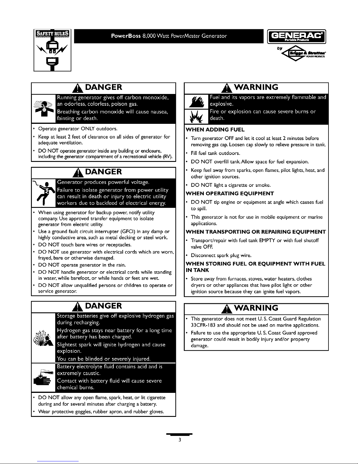
DANGER
Operate generator ONLY outdoors.
Keepat least 2 feet of clearance on all sides of generator for
adequate ventilation.
DO NOT operategenerator insideanybuildingor enclosure,
includingthegenerator compartmentof arecreationalvehicle(RV).
DANGER
When usinggenerator for backup power, notify utility
company.Use approved transfer equipment to isolate
generator from electric utility.
Use a ground fault circuit interrupter (GFCi) in anydamp or
highly conductive area,such as metal decking or steel work.
DO NOT touch bare wires or receptacles.
DO NOT use generator with electrical cords which are worn
frayed,bare or otherwise damaged.
DO NOT operate generator in the rain.
DO NOT handle generator or electrical cords while standing
inwater, while barefoot, or while handsor feet are wet.
DO NOT allow unqualified persons or children to operate or
service generator.
DANGER
DO NOT allow any open flame,spark, heat,or lit cigarette
during andfor several minutes after charging a battery.
Wear protective goggles,rubber apron, and rubber gloves.
, WARNING
WHEN ADDING FUEL
Turngenerator OFF and let it cool at least 2 minutes before
removing gas cap.Loosen cap slowly to relieve pressure in tanlc
Fill fuel tank outdoors.
DO NOT overfill tank.Allow spacefor fuel expansion.
Keep fuel awayfrom sparks,open flames, pilot lights, heat, and
other ignitionsources.
DO NOT light acigarette or smoke.
eVHEN OPERATING EQUIPMENT
DO NOT tip engine or equipment at angle which causesfuel
to spill.
Thisgenerator isnot for use in mobile equipment or marine
applications.
'HEN TRANSPORTING OR REPAIRING EQUIPMENT
Transportlrepair with fuel tank EMPTY or with fuel shutoff
valve OFE
Disconnect spark plugwire.
_HEN STORING FUEL OR EQUIPMENT WITH FUEL
IN TANK
Store awayfrom furnaces, stoves, water heaters, clothes
dryers or other appliancesthat havepilot light or other
ignition source becausethey can ignite fuel vapors.
, WARNING
Thisgenerator does not meet U. S.Coast Guard Regulation
33CFR-183 and should not be used on marine applications.
Failure to use the appropriate U. S.Coast Guard approved
generator could result in bodily iniury and/or property
damage.
mm_mm
3
Page 4
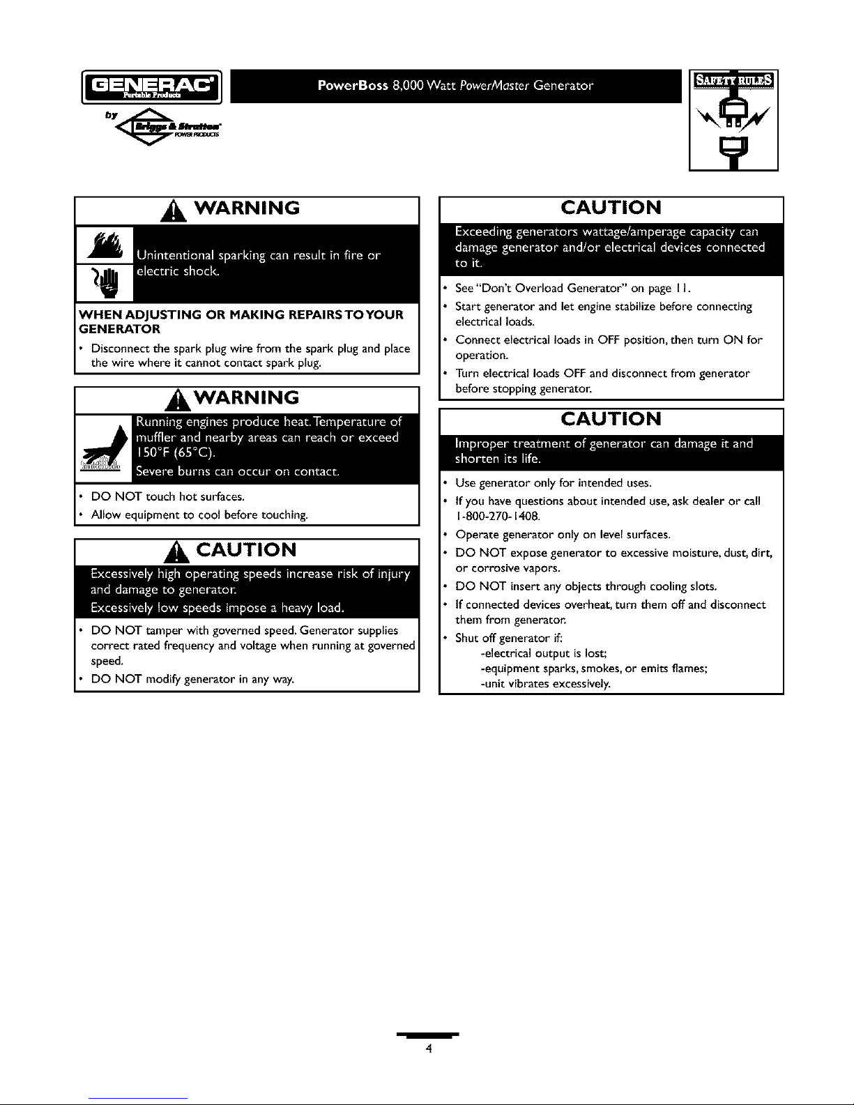
WARNING
;ENERATOR
Disconnect the spark plug wire from the spark plug and place
the wire where it cannot contact spark plug.
, WARNING
DO NOT touch hot surfaces.
Allow equipment to cool before touching.
CAUTION
DO NOT tamper with governed speed.Generator supplies
correct rated frequency and voltage when running at governed
speed.
DO NOT modify generator in any way.
CAUTION
See"Don't Overload Generator" on page I I.
Start generator and let engine stabilize before connecting
electrical loads.
Connect electrical loads in OFF position, then turn ON for
operation.
Turn electrical loads OFF and disconnect from generator
before stopping generator.
CAUTION
Use generator only for intended uses.
tf you have questions about intended use,ask dealer or call
1-800-270-1408.
Operate generator only on levelsurfaces.
DO NOT expose generator to excessive moisture, dust, dirt,
or corrosive vapors.
DO NOT insert any objects through cooling slots.
tf connected devices overheat, turn them off and disconnect
them from generatoc
Shut off generator if.'
-electrical output is lost;
-equipment sparks,smokes,or emits flames;
-unit vibrates excessively.
/
4
Page 5
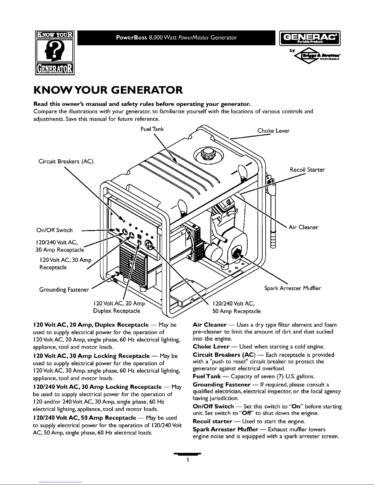
KNOWYOUR GENERATOR
Read this owner's manual and safety rules before operating your generator.
Compare the illustrations with your generator, to familiarize yourself with the locations of various controls and
adjustments. Save this manual for future reference.
Fuel Tank Choke Lever
Circuit Breakers (AC)
\
Recoil Starter
OnlOff Switch
120/240 Volt AC,
30Am
.'leaner
Receptacle
Grounding Fastener
120Volt AC, 20 Amp
Duplex Receptacle
120 Volt AC, 20 Amp, Duplex Receptacle -- May be
used to supply electrical power for the operation of
120Volt AC, 20 Amp, single phase, 60 Hz electrical lighting,
appliance, tool and motor loads.
120 Volt AC, 30 Amp Locking Receptacle -- May be
used to supply electrical power for the operation of
120Volt AC, 30 Amp, single phase, 60 Hz electrical lighting,
appliance, tool and motor loads.
120/240 Volt AC, 30 Amp Locking Receptacle -- May
be used to supply electrical power for the operation of
120 andlor 240 Volt AC, 30 Amp, single phase, 60 Hz
electrical lighting, appliance, tool and motor loads.
1201240 Volt AC, 50 Amp Receptacle -- May be used
to supply electrical power for the operation of 1201240Volt
AC, 50 Amp, single phase, 60 Hz electrical loads.
SparkArrester Muffler
120/240Volt AC,
50 Amp Receptacle
Air Cleaner -- Uses a dry type filter element and foam
pre-cteaner to limit the amount of dirt and dust sucked
into the engine.
Choke Lever -- Usedwhen starting a cold engine.
Circuit Breakers (AC) -- Eachreceptacle is provided
with a "push to reset" circuit breaker to protect the
generator againstelectrical overload.
FuelTank -- Capacity of seven(7) U.S.galtons.
Grounding Fastener -- If required, pleaseconsult a
qualified electrician, electrical inspector, or the local agency
havingjurisdiction.
On/Off Switch -- Set this switch to "On" before starting
unit. Set switch to "Off' to shut clown the engine.
Recoil starter -- Used to start the engine.
Spark Arrester Muffler -- Exhaust muffler lowers
engine noise andis equipped with a spark arrester screen.
/
5
Page 6
ASSEMBLY
Your generator requires some assemblyand is ready for
use after it has been properly serviced with the
recommended oil and fuel.
If you have any problems with the assembly of your
generator, please call the generator helpline at
1-800-270-1408.
Remove Generator From Carton
• Set the palteted carton on a rigid flat surface.
• Carefully cut bandsaround the shipping carton.
• Lift carton off the generator.
• Remove all packing material, carton fillers, etc.
• Remove the generator from the shipping pallet.
Carton Contents
Check all contents. Ifany parts are missingor damaged,call
the generator helpline at 1-800-270-1408.
The generator
Electric start battery cables
Generator and engineowner's manuals
Locking 30Amp plugs
Battery mounting bracket/hardware
2 bottles engine oil
Wheel kit
INSTALL WHEEL KIT
NOTE: Wheel kit is not intendedfor over-the-road use.
To installyour wheel kit, you needthe following toot:
• Socket wrench with I/2" or 13mm sockets.
• Neddle-nose pliers
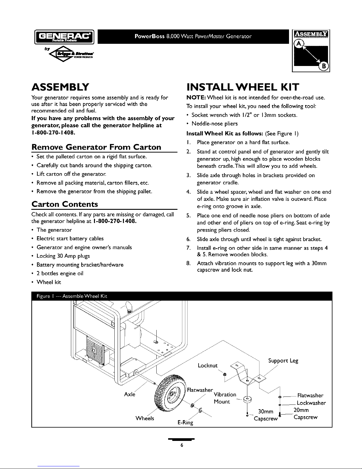
InstallWheel Kit as follows: (SeeFigure I)
I. Placegenerator on a hard flat surface.
2. Standat control panel end of generator and gently tilt
generator up,high enough to placewooden blocks
beneath cradle.This will allow you to add wheels.
3. Slide axle through holes in brackets provided on
generator cradle.
4. Slide a wheel spacer,wheel and flat washer on one end
of axle. Make sure air inflationvalve isoutward. Place
e-ring onto groove in axle.
5. Placeone end of needle nose pliers on bottom of axle
and other end of pliers on top of e-ring.Seat e-ring by
pressing pliers closed.
6. Slideaxlethrough until wheel istight againstbracket.
7. Install e-ring on other side in same manner as steps4
& 5. Removewooden blocks.
8. Attach vibration mounts to support leg with a 30mm
capscrew and lock nut.
J
Wheels
J
Locknut
Flatwasher
/ Vibration
_ Mount --
E-Ring
,_port Leg
_-- Flatwasher
__ Lockwasher
30mm _ 20mm
-Capscrew Capscrew
/
6
Page 7
9. Withwheelson,securesupportlegassemblytocradle
with20mmlongcapscrews,flatwashers,andlock
washers.
10.Checkeachfastenertoensureitissecureandtires
areinflatedbetween15-40PSI.
INSTALLING BATTERY
NOTE: The generator can be started manually.If you
choose not to use the electric start feature of this
generator, you do not need to install the battery.
_ AUTION! Ifbattery is not installed,DO NOT
operate engine without insulatingthe red positive
battery cable with electrical tape, or it could blow a
fuse and causesparks.
We recommend you purchase and install a Briggs &
Stratton 12Volt DC battery (Group U I;Type GT-X).The
battery should be serviced with electrolyte fluid and fully
charged prior to installation.
Install the battery as follows:
I. Find battery fasteners shipped loose in carton.
2. Set battery onto tray.
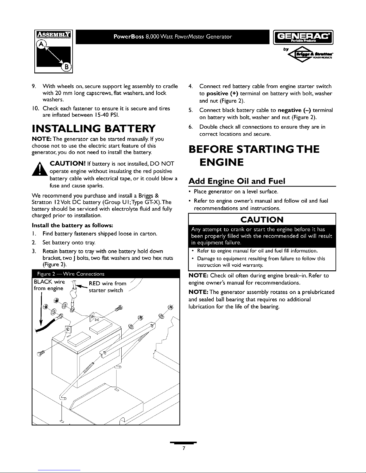
3. Retainbattery to tray with one battery hold down
bracket,two Jbolts,two fiat washersandtwo hex nuts
(Figure2).
4. Connect red battery cablefrom engine starter switch
to positive (+) terminal on battery with bolt, washer
and nut (Figure 2).
5. Connect black battery cable to negative (-) terminal
on battery with bolt, washer and nut (Figure 2).
6. Double check all connections to ensure they are in
correct locations and secure.
BEFORE STARTING THE
ENGINE
Add Engine Oil and Fuel
• Place generator on a level surface.
• Refer to engine owner's manualand follow oil and fuel
recommendations and instructions.
CAUTION
• Refer to engine manualfor oil andfuel fill information.
• Damage to equipment resulting from failure to follow this
instructionwill void warranty.
NOTE: Check oil often during engine break-in. Refer to
engine owner's manualfor recommendations.
NOTE: The generator assembly rotates on a pretubricated
and sealed ball bearing that requires no additional
lubricationfor the lifeof the bearing.
/
7
Page 8
USING THE GENERATOR
System Ground
The generator hasa systemground that connects the
generator frame components to the ground terminals on
the AC output receptacles.The systemground is connected
to theAC neutral wire (the neutral is bonded to the
generator frame).
Special Requirements
There may be Federalor State Occupational Safety and
Health Administration (OSHA) regulations,localcodes,or
ordinances that apply to the intendeduseof the generator.
Pleaseconsult a qualified electrician, electrical inspector,or
the localagencyhavingjurisdiction.
• In some areas,generators are required to be registered
with localutilitycompanies.
• If the generator isusedat aconstruction site,there may
be additional regulations which must be observed.
Connecting to a Building's Electrical
System
Connections for standby power to a buitding's electrical
system must be made by a qualified electrician.The
connection must isolate the generator power from utility
power, and must comply with all applicable lawsand
electrical codes.
DANGER
When usinggenerator for backup power, notifyutility
company.Use approved transfer equipment to isolate
generator from electric utility.
Use a ground fault circuit interrupter (GFCI) in anydamp or
highly conductive area,such as metal decking or steel work.
DO NOT touch bare wires or receptacles.
DO NOT use generator with electrical cords which are worn
frayed,bare or otherwise damaged.
DO NOT operate generator in the rain.
DO NOT handle generator or electrical cords while standing
inwater, while barefoot, or while handsor feet are wet.
DO NOT allow unqualified persons or children to operate or
service generator.
OPERATING THE
G EN ERATO R
CAUTION
See"Don't Overload Generator" on page I I.
Start generator and let engine stabilize before connecting
electrical loads.
Connect electrical loads in OFF position, then turn ON for
operation.
Turn electrical loads OFF and disconnect from generator
before stopping generator.
Starting the Engine
Disconnect altelectrical loadsfrom the generator. Use the
following start instruction steps by numerical order:
I. Make sure unit is on a levelsurface.
IMPORTANT: Failureto start and operate unit on a level
surface will causethe unit not to start or shut down during
operation.
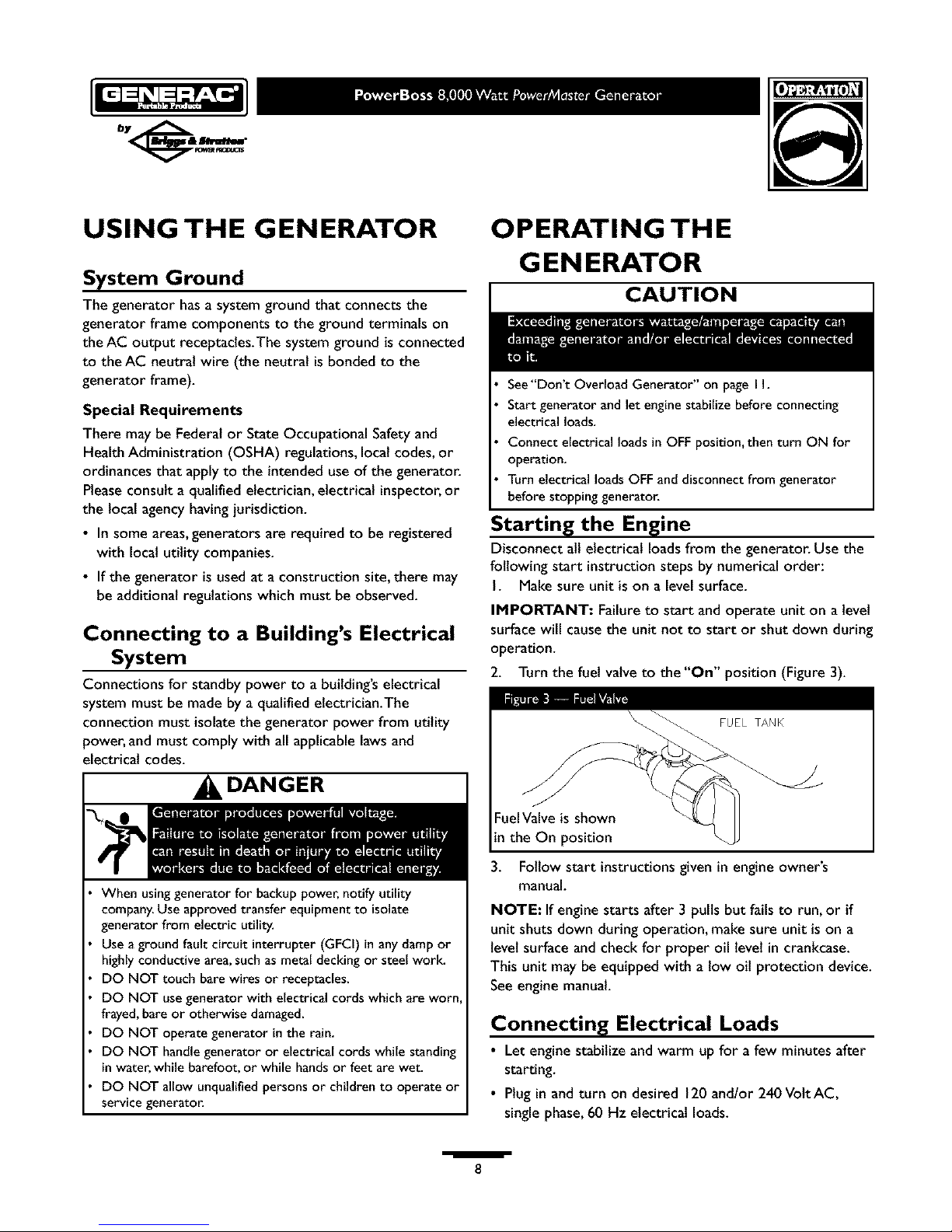
2. Turn the fuel valve to the "On" position (Figure 3).
Fuel Valve is shown
in the On position
3. Follow start instructions given in engine owner's
manual.
NOTE: If engine starts after 3 pulls but fails to run, or if
unit shuts down during operation, make sure unit is on a
level surface and check for proper oil level in crankcase.
This unit may be equipped with a low oil protection device.
See engine manual.
Connecting Electrical Loads
• Let enginestabilize and warm upfor a few minutes after
starting.
• Plug in and turn on desired 120 and/or 240VottAC,
singlephase,60 Hz electrical loads.
/
8
Page 9
• DO NOT connect 240Volt loads to 120Volt receptacles.
• DO NOT connect 3-phase loads to generator.
• DO NOT connect 50 Hz loads to generator.
• DO NOT OVERLOADTHE GENERATOR. See
"Don't Overload Generator" on page 1I.
Stopping the Engine
I. Unplug all electrical loads from generator panel
receptacles.NEVER start or stop enginewith electrical
devices plugged in and turned ON.
2. Let engine run at no-load for several minutes to
stabilize internal temperatures of engine and generator.
3. Turn engine off according to instructions given in the
engine owner's manual.
4. Movefuel valveto "Off" position.
COLD WEATH ER
OPERATION
Under certain weather conditions (temperatures below
40°F [4°C] and a high clew point), your generator may
experience icing of the carburetor and/or the crankcase
breather system.
Build a structure that will enclose three sides and the top
of the generator:
I. Make sure entire muffler-side of generator is exposed.
Note that your generator mayappear different from
that shown in Figure 4.
2. Ensurea minimum of two feet clearance between open
side of box and nearest object.
3. Faceexposed end away from wind and elements.
4. Enclosureshould hold enough heat created by
generator to prevent problems.
_, DANGER
Operate generator ONLY outdoors.
Keep at least 2 feet of clearance on all sides of generator for
adequate ventilation.
DO NOT operate generator inside any building or enclosure,
including the generator compartment of a recreational vehicle (RV).
Remove generator from shelter when temperature is above
40°F [4°C].
RECEPTACLES
_, CAUTION
NEVER attempt to power a device requiring more
amperagethan generator or receptacle can supply.
DO NOT overload the generator. See"Don't Overload
Generator".
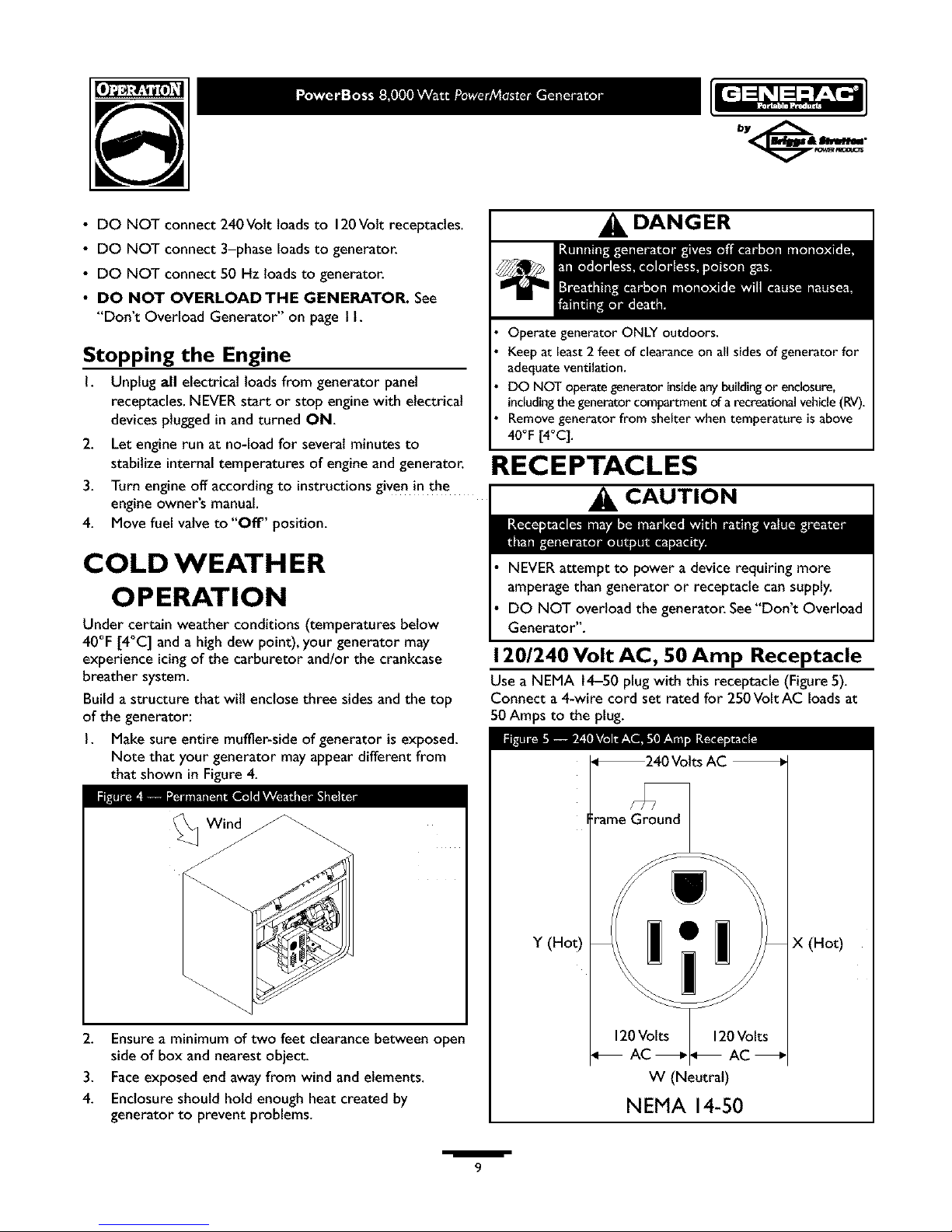
120/240 Volt AC, 50 Amp Receptacle
Use a NEMA 14-50 plugwith this receptacle (Figure5).
Connect a 4-wire cord set rated for 250Volt AC loads at
50 Amps to the plug.
F
Y (Hot)
_240 Volts AC
rame Ground
X (Hot)
W (Neutral)
NEMA 14-50
I
9
Page 10
Usethisreceptacletooperate240VoltAC,60Hz,single
phaseloadsrequiringupto8,000watts(8.0kW)ofpower.
Theoutletisprotectedbya35Amppush-to-resetcircuit
breaker.
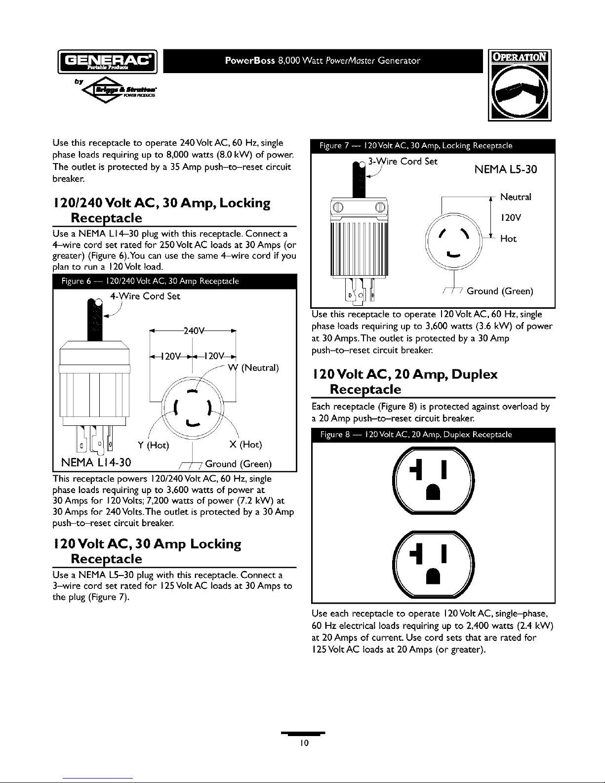
120/240 Volt AC, 30 Amp, Locking
Receptacle
Use a NEMA LI4-30 plug with this receptacle.Connect a
4-wire cord set rated for 250Volt AC loads at 30 Amps (or
greater) (Figure 6).You can use the same4-wire cord if you
)lanto run a 120Volt load.
4-Wire Cord Set
i
f
(Neutral)
Y (Hot) | X (Hot)
NEMA L14-30 /_ Ground(Green)
This receptacle powers 1201240Volt AC, 60 Hz,single
phase loads requiring up to 3,600 watts of power at
30 Amps for 120Volts;7,200 watts of power (7.2 kW) at
30 Amps for 240Volts.The outlet is protected by a 30 Amp
push-to-reset circuit breaker.
120 Volt AC, 30 Amp Locking
Receptacle
Use a NEMA L5-30 plug with this receptacle. Connect a
3-wire cord set rated for 125Volt AC loads at 30Amps to
the plug (Figure 7).
_ire Cord Set NEMA L5-30
Neutral
120V
Hot
Ground (Green)
Usethis receptacle to operate 120VoltAC, 60 Hz, single
phaseloads requiring up to 3,600 watts (3.6 kW) of power
at 30Amps.The outlet is protected by a 30Amp
push-to-reset circuit breaker.
120 Volt AC, 20 Amp, Duplex
Receptacle
Eachreceptacle (Figure 8) is protected against overload by
a 20 Amp push-to-reset circuit breaker.
Use each receptacle to operate 120Volt AC, single-phase,
60 Hz electrical loads requiring up to 2,400 watts (2.4 kW)
at 20Amps of current. Use cord sets that are rated for
125Volt AC loads at 20Amps (or greater).
i
10
Page 11

DON'T OVERLOAD
G EN ERATO R
Capacity
You must make sure your generator cansupply enough
rated (running) and surge (starting) watts for the itemsyou
will power at the sametime. Follow these simple steps:
I. Select the itemsyou wilt power at the same time.
2. Total the rated (running) watts of these items.Thisis
the amount of power your generator must produce to
keep your itemsrunning. SeeFigure 9.
3. Estimatehow many surge (starting) watts you wilt
need.Surge wattage isthe short burst of power
needed to start electric motor-driven tools or
appliancessuch asa circular saw or refrigerator.
Becausenot all motors start at the sametime, total
surge watts can be estimated by addingonly the
item(s)with the highest additional surge watts to the
total rated watts from step 2.
Example:
Tool or Appliance
Window Air
Conditioner
Refrigerator
Deep Freezer
Television
Light (75 Watts)
Rated (Running)
Watts
1200
800
500
500
75
3075 Total
Running Watts
Total Rated (Running)Watts = 3075
Highest Additional SurgeWatts = 1800
Total Generator Output Required = 4875
Additional Surge
(Starting)Watts
1800
1600
500
1800 Highest
SurgeWatts
Power Management
To prolong the lifeof your generator and attached devices,
it is important to take care when addingelectrical loadsto
your generator.There should be nothing connected to the
generator outlets before starting its engine.The correct
and safeway to managegenerator power is to sequentially
add loadsas follows:
I. With nothingconnected to the generator, start the
engine asdescribed in this manual.
2. Plugin and turn on the first load,preferably the largest
loadyou have.
3. Permit the generator output to stabilize (engine runs
smoothly and attached device operates properly.
4. Plug in and turn on the next load.
5. Again,permit the generator to stabilize.
6. Repeat steps 4 and 5 for each additional load.
NEVER add more loadsthan the generator capacity.Take
specialcare to consider surgeloads in generator capacity,
asdescribed above.
Tool or Appliance
Essentials
LightBulb - 75 watt
Deep Freezer
SumpPump
Refrigerator/Freezer - 18Cu. Ft.
Water Well Pump- I/3 HP
Heatin_Coolin_
Window AC - 10,000 BTU
Window Fan
FurnaceFanBlower - I/2 HP
Kitchen
Microwave Oven - 1000Watt
Coffee Maker
Electric Stove - SingleElement
Hot Plate
Family Room
DVD/CD Player
VCR
Stereo Receiver
Color Television - 27"
Personal Computer w/I 7" monitor
Other
SecuritySystem
AM/FM Clock Radio
GarageDoor Opener - I/2 HP
Electric Water Heater - 40 Gallon
DIY/Job Site
Quartz Halogen Work Light
Airless Sprayer - I/3 HP
Reciprocating Saw
Electric Drill - I/2 HP
Circular Saw - 7 I/4"
Miter Saw- I0"
Table Planer - 6"
Table Saw/RadialArm Saw- I0"
Air Compressor - I-I/2 HP
Additional
Rated*
(Running) Surge
(Starting)
Watts
Watts
75
500 500
800 1200
800 1600
1000 2000
1200 1800
300 600
800 1300
1000
1500
1500
2500
100
100
450
500
8O0
180
300
480 520
40O0
1000
600 1200
960 960
1000 1000
1500 1500
1800 1800
1800 1800
2000 2000
2500 2500
*Wattages listedare approximate only.Check toot or
appliancefor actual wattage.
/
II
Page 12

SPECIFICATIONS
Maximum SurgeWatts ................ I0,000 watts
Continuous Wattage Capacity ........... 8,000 watts
Power Factor .............................. 1.0
Rated Maximum Continuous AC Load Current:
At 120Volts ....................... 66.6Amps
At 240 Volts ....................... 33.3Amps
Phase................................. I-phase
Rated Frequency ....................... 60 Hertz
FuelTank Capacity................... 7 U.S.gallons
ShippingWeight ......................... 290 Ibs.
GENERAL MAINTENANCE
RECOMMENDATIONS
The Owner/Operator is responsible for making sure that
all periodic maintenance tasksare completed on atimely
basis;that all discrepancies are corrected; and that the unit
is kept clean and properly stored. NEVER operate a
damaged or defective generator.
Engine Maintenance
See engine owner's manualfor instructions.
CAUTION
Used motor oil hasbeen shown to causeskin cancer in
certain laboratory animals.
Thoroughly wash exposed areas with soap and water.
KEEPOUT OF REACH OF CHILDREN. DON'T
POLLUTE.CONSERVERESOURCES.RETURN
USED OIL TO COLLECTION CENTERS.
Generator Maintenance
Generator maintenance consists of keeping the unit clean
and dry. Operate and store the unit in a clean dry
environment where it will not be exposed to excessive
dust, dirt, moisture or any corrosive vapors. Cooling air
slots in the generator must not become clogged with snow,
leaves or any other foreign material.
NOTE: DO NOT use a garden hose to clean generator.
Water can enter engine fuel system and causeproblems. In
addition, ifwater enters generator through cooling air slots,
some of the water wilt be retained in voidsand cracks of
the rotor and stator winding insulation.Waterand dirt
buildup on the generator internalwindings will eventually
decreasethe insulationresistance of these windings.
ENERATOR
WARNING
Disconnect the spark plug wire from the spark plugand place
the wire where it cannot contact spark plug.
Generator Cleaning
• Use a damp cloth to wipe exterior surfaces clean.
CAUTION
DO NOT expose generator to excessive moisture, dust, dirt,
or corrosive vapors.
DO NOT insert any objects through cooling slots.
Use a soft bristle brush to loosen caked on dirt or oil.
Use a vacuum cleaner to pick up loose dirt and debris.
Use low pressure air (not to exceed 25 psi) to blow
away dirt. Inspect cooling air slots and opening on
generator.These openings must be kept clean and
unobstructed.
I
12
Page 13

STO RAG E
The generator should be started at least once every seven
claysand allowed to run at least 30 minutes. If this cannot
be done andyou must store the unit for more than
30 days,use the following guidelinesto prepare it for
storage.
Generator Storage
• Clean the generator as outlined in"Generator Cleaning".
• Check that cooling air slots and openings on generator
are open and unobstructed.
WARNING
DO NOT place a storage cover over a hot generator.
Let equipment cool for a sufficient time before placing the
cover on the equipment.
Engine Storage
See engine owner's manualfor instructions.
Other Storage Tips
• To prevent gum from forming in fuel system or on
essential carburetor parts, add fuel stabilizer into fuel
tank and fill with fresh gasoline. Run the unit for several
minutes to circulate the additive through the carburetor.
The unit and fuel can then be stored for up to
24 months. Fuel stabilizer can be purchased locally.
• DO NOT store gasoline from one season to another
unless it has been treated as described above.
• Replace fuel container if it starts to rust. Rust and/or dirt
in fuel can cause problems if it's used with this unit.
• Store unit in a clean and dry area.
I
13
Page 14

TROUBLESHOOTING
Problem
No AC output is available, but
generator is running.
Cause
I. One of the circuit breakers is
open.
2. Faultin generator.
3. Poor connection or defective
cord set.
4. Connected device is bad.
Correction
I. Resetcircuit breaker.
2. Contact Authorized service
facility.
3. Check and repair.
4. Connect another device that is in
good condition.
I. Short circuit in a connected load. I. Disconnect shorted electrical
Generator runs good at no-load load.
but "bogs" down" when loads are 2. Generator is overloaded. 2. See "Don't Overload Generator".
connected. 3. Shorted generator circuit. 3. Contact Authorized service
facility.
Generator will not start; or starts Low oil level. Fill crankcase to proper level or place
and runs rough, generator on level surface.
I. Out of gasoline. I. Fill fuel tank.
Generator shuts down during
operation. 2. Low oil level. 2. Fill crankcase to proper level or
place generator on level surface.
Generator lacks power. Load is too high. See "Don't Overload Generator".
/
14
Page 15

NOTES
I
IS
Page 16

SCHEMATIC
66 77
FUSE 77
lO AHp J
13 _2_ra
_ _hYST_
EXCITATION
COIL
qk
CAPACITDR
POWER POWER
_INDING XINDING
_ BLK BLU
_i ENG
IGNITIDN
8 B
IIA
I
16
Page 17

WIRING DIAGRAM
I
17
Page 18

g--s
EXPLODEDVIEW- MAIN UNIT
10
5
6
\
/ \_ TO STARTER
61 \_TO + TERMINAL
ON BAWERY
72 18
/
25
52 13 55
18 s2_ 55
/
51 /
56
77
/ 54
46
57
19
11
26
25
65
,mira
18
Page 19

2-
_r3
PARTS LIST- MAIN UNIT
Item Part # Description Item Part #
I NSP ENGINE 50 84794GS
2 BI89039GS CRADLE 51 47411GS
3 877304GS SUPPORT,Engine 52 22473GS
4 77816GS DECAL, Caution Hot Muffler 53 76040GS
5 93826GS DECAL, Start Instructions 54 84268GS
6 92982GS DECAL, Danger 55 JI89091GS
7 84363GS CAP,FuelTank 56 46476GS
8 48031CGS CLAMP,Hose 57 225| IGS
9 30340GS HOSE 58 22287GS
10 193633GS ASSY,Tank,Fuel 59 78289GS
(Includes Items 5,6 & 39) 60 77282GS
II 84135GS PIN 61 1892988GS
12 83465GS GROMMET,FueITank Mounting 62 22127GS
13 96832GS CLAMP,Cable 63 22097GS
14 23152GS SCREW 64 185939GGS
15 22237GS WASHER, Lock 65 187856GS
16 22241GS NUT 71 56893GS
17 75246GS SCREW 72 91526GS
18 55934GGS CLAMP,Hose 75 189286GS
19 J93074GS SUPPORT,HeatShleld 76 189155GS
20 189302AGS ASSY,Wire, Starter 77 187049GS
21 38353GS MOUNTS,Vibration 78 192280GS
23 22145GS WASHER
24 B4986GS DECAL, Ground
25 26850GS WASHER Items Not Shown
26 49820GS NUT, Nylok 189065GS
27 187104GS WASHER, Nylon MS5375
28 39287GS SCREW MS6497
29 B85586GS HANDLE (Includes Item 30) 193347GS
30 84605GS GRIP 807948
31 189051GS ASSY,Control Panel(see page21) 807595
32 82153GS SCREW 805812
34 73054GS DECAL, Fuel Shut-Off 392154
35 87680GS NUT,Wing 690661
36 45757GS SCREW 692056
37 49813GS NUT 692359
38 1955362|GS ASSY,Wire, Ground BB3061GS
39 192980GS KIT,Valve,Fuel 43438GS
43 52856GS NUT, Lock 37806GS
44 62265GS GROMMET 193634GS
45 27482GS WASHER
46 42907GS SCREW
47 22131GS WASHER
48 52618GS SCREW
49 49226GS WASHER, Lock
Description
GROMMET,Generator Cover
SCREW
WASHER
SCREW
ASSY,Alternator (seepage22)
SHIELD,Heat
CAP,Plug
SCREW
SCREW
BRACKET,Starter Switch
SWITCH, Starter
CABLE, B_ttery Positive
NUT
WASHER, Lock
CABLE, Battery Negative
KIT,Hardware Tray and Battery
SCREW
SCREW
SCREW
WASHER
PLUG, Domed
HOSE BARB
MANUAL, Owners
MANUAL, Engine
SHEET,Instruction
KIT,Battery Hardware
MUFFLER
CLAMP,M_er
BRACKET,Muffler
ARRESTOR,Spark
SCREW
BOLT
SCREW
OIL, Bottle
PLUG,240V,30A
PLUG, 125V,30A
KIT,Decal Service
Optional Accessories Not Included
84883GS Cord Wrap
43630GS 120/240 Volt AC 50 Amp Plug
19
Page 20

2 ¸
_r3
EXPLODEDVIEWAND PARTS LIST-WHEEL KIT
10
/
4
Item
I
2
3
4
5
6
7
8
9
10
II
Part #
191267JGS
B4966GS
191265GS
22247GS
191413GS
22145GS
22413GS
39253GS
22129GS
B189085GS
192432GS
Description
AXLE
WHEEL
E_RING
WASHER
VIBE MOUNT, with Washer
WASHER
SCREW
SCREW
WASHER, Lock
LEG,Support
NUT, Lock
/
20
Page 21

2 ¸
_rs
EXPLODED VIEW AND PARTS LIST- CONTROL PANEL
lO
17
k
10
8
18
Item Part #
I BB4461AGS
2 23897GS
3 49226GS
4 91526GS
5 78653GS
6 82881GS
7 B4262GS
8 75207GS
9 75207NGS
I0 75207AGS
II 68759GS
12 23365GS
13 68868GS
14 43437GS
15 51715GS
Description Item Part #
PANEL,Control 16 43I80GS
WASHER 17 22264GS
WASHER, Lock 18 80077GS
SCREW 19 75476GS
SWITCH 20 92953GS
WASHER, Lock 21 189127GS
OUTLET, 50A, 240V 22 51714GS
BREAKER,Circuit 23 186102GS
BREAKER,Circuit 24 B4893GS
BREAKER,Circuit 25 BI89104GS
OUTLET, 20A, 120V 26 B4894GS
WASHER 27 43181GS
OUTLET, 30A, 120VLocking 28 43182GS
OUTLET, 30A, 120V/240V Locking 29 B4892GS
NUT 30 77314GS
17
Description
WASHER
WASHER, Lock
SCREW
SCREW
BLOCK,Terminal, 50A
GROMMET,Rubber
NUT
ASSY,Wire Harness
BRACKET,Resistor
BOX, Control Panel
RECTIFIER,Battery Charge
SCREW
WASHER, Lock
RESISTOR,2 OHM, 25W
RELAY,Time Relay
/
21
Page 22

2 ¸
_r3
EXPLODED VI EW AND PARTS LIST - ALTERNATOR
17
9
12
7
3
5
16
15
Item Part # Description
I B4906GS SHIELD,Front
2 B4907GS GRID, Front
3 B4908GS BOLT,Shaft Stay
4 B4909GS BOLT,Stay
5 B4910GS ASSY,Housing
6 187049GS PLUG,Domed
7 B4912GS COVER, Blind End
8 B4913GS COVER,Top Black
9 B4914GS CAPACITOR
I I B4916GS CAPACITOR, Diode +Varistor + EMC
12 191297GS ASSY,Rotor (Includes Item I I)
14 B4919GS SCREW
15 B4920GS SCREW
16 49820GS NUT, Lock
17 188928GS CONNECTOR, 6-Pin Sincro
18 22473GS WASHER
19 49813GS NUT
/
22
Page 23

GENERAC PORTABLE PRODUCTS OWNER EQUIPMENT WARRANTY POLICY
LIMITED WARRANTY
"Generac Portable Products isa licensedtrademark of Briggs& Stratton Power Products.Briggs& Stratton Power Products will
repair or replace,free of charge,any part, or parts of the equipment** that are defective in material or workmanship or both.
Transportation charges on parts submitted for repair or replacement under this warranty must be borne by purchaser.This
warranty iseffective for the time periods and subject to the conditions provided for in this policy.For warranty service,find your
nearest Authorized service dealer by calling 1-800-270-1408.Warranty service may only be performed by a Briggs& Stratton
Power ProductsAuthorized service dealer.
THERE ISNO OTHER EXPRESSWARRANTY. IMPLIEDWARRANTIES, INCLUDING THOSE OF MERCHANTABILITY AND
FITNESSFORA PARTICULAR PURPOSE,ARELIMITED TO THE TIME PERIOD SPECIFIED,OR TO THE EXTENT PERMITTED
BY LAW.ANY AND ALL IMPLIEDWARRANTIES ARE EXCLUDED. LIABILITY FOR CONSEQUENTIAL DAMAGES UNDER
ANYANDALLWARRANTIESARE EXCLUDEDTOTHE EXTENT EXCLUSION ISPERMITTED BY LAW.Some countries or
states do not allow limitations on how long an impliedwarranty lasts,and some countries or states do not allow the exclusion or
limitation of incidentalor consequentialdamages,so the abovelimitation and exclusion maynot apply to you.This warranty gives
you specific legal rights andyou mayalso haveother rights that vary from country to country or state to state."
WARRANTY PERIOD*
PRODUCTS** CONSUMER USE COMMERCIAL USE
PressureWasher I year 90 days
Portable Generator 2 years (2nd year parts only) I year
*The warranty period beginson the date of purchase by the first retail consumer or commercial end user,and continues for the
period of time stated in the table above."Consumer use" meanspersonal residential household use by a retail consumer.
"Commercial use" meansall other uses,includinguse for commercial, incomeproducing or rental purposes.Once equipment has
been used commercially, it shall thereafter be considered to be in commercial usefor purposes of this warranty.
**The engine and starting batteries are warranted solely by the manufacturers of those products.
WARRANTY REGISTRATION IS NOT NECESSARYTO OBTAIN WARRANTY ON BRIGGS & STRATTON POWER
PRODUCTS EQUIPMENT.SAVEYOUR PROOF OF PURCHASE RECEIPT.IFYOU DO NOT PROVIDE PROOF OFTHE
INITIAL PURCHASE DATEATTHETIMEWARRANTY SERVICE IS REQUESTED, THE MANUFACTURING DATE OFTHE
EQUIPMENTWILL BEUSEDTO DETERMINETHEWARRANTY PERIOD.
About your equipment warranty:
We welcome warranty repair and apologizeto you for being inconvenienced.AnyAuthorized service dealermay perform warranty
repairs.Most warranty repairs are handled routinely,but sometimes requestsfor warranty service may not beappropriate. For
example,warranty service would not applyifequipment damageoccurred becauseof misuse,lackof routine maintenance,shipping,
handling,warehousingor improperinstallation.Similarly,the warranty isvoid if the manufacturingdate or the serialnumber on the
equipment hasbeen removed or the equipment has been altered or modified.During the warranty period,the Authorized service
dealer,at its option, wilt repair or replaceany part that, upon examination,isfound to be defective under normal useand service.This
warranty wilt not cover following repairs and equipment:
• Normal Wear: Outdoor power equipment, likeall mechanical devices,needs periodic parts,service and replacement to perform
well.This warranty does not cover repair when normal use hasexhausted the life of a part or the equipment.
• Installation and Maintenance: This warranty does not applyto equipment or parts that havebeensubjectedto improperor
unauthorized installationor alteration and modification,misuse,negligence,accident,overloading,overspeeding,improper
maintenance,repair or storage soas,in our judgment,to adverselyaffect itsperformance and reliability.Thiswarranty also does not
cover normal maintenancesuchasadjustments,fuel systemcleaningand obstruction (due to chemical,dirt, carbon or lime,etc.).
• Other Exclusions: Also excluded from this warranty are wear itemssuch as quick couplers, oil gauges,belts, o-rings, filters,
pump packing,etc., pumps which havebeen run without water supplied or damageor malfunctions resulting from accidents,
abuse,modifications, alterations, or improper servicing or freezing or chemical deterioration.Accessory parts such asguns,
hoses,wands and nozzles are excluded from the product warranty.Also excluded is used,reconditioned, and demonstration
equipment; equipment used for prime power in place of utility power and equipment used in life support applications.
BRIGGS & STRATTON POWER PRODUCTS GROUP, LLC
JEFFERSON,WISCONSIN, U.S.A.
Page 24

TABLA DE CONTENIDOS
ReglasDe Seguridad .............................. 24-26
Conozca Su Generador .............................. 27
Ensamblaje...................................... 28-29
Funcionamiento .................................. 30-33
Mantenimiento ..................................... 34
AImacenamiento .................................... 35
Diagnosticos De Averfas .............................. 35
Garantia .......................................... 36
DESCRIPCI( N DEL EQUIPO
_Lea este manual de manera cuidadosa y
familiaricese con su generador. Conozca sus usos,
sus limitaciones y cualquier peligro relacionado
con el mismo.
Este generador funciona en base a un motor, de campo el_ctrico
giratorio y de corriente alterna (AC). Fue diseffado con la
finalidad de proveer energia el_ctrica para luces el_ctricas,
aparatos, herramientas compatibles y cargas de motor. El campo
giratorio del generador funciona a una velocidad de 3,6000 rpm
usando un motor.
iPRECAUCI(_N! NO sobrepaselacapacidadde vataiey amperaie
delgenerador.Revise"No SobrecargueGenerador" en lap_gina33.
Se ha hecho cadaesfuerzo posible para asegurarse que la
informaci6n que aparece en este manual es exacta y se encuentra
actualizada.Sin embargo, nosotros se reserva el derecho a
cambiar,alterar o de otra manera mejorar, el producto y este
documento en cualquier momento, sin previo aviso.
El Sistema de Control de Emisiones para este generador est_
garantizado para iuegos est_ndarespor laAgencia de Protecci6n
Ambiental. Para mayor informaci6n acerca de la garantfa,consulte
con el manualdel propietario del motor.
Enel estado de California es obligatorio, seg_n la ley,el uso de
_pagachispas(Secci6n 4442 del C6digo de Recursos P_blicos de
California). Otros estados pueden tener leyessimilares.Lasleyes
_ederalesse aplicanen tierras federales.Si equipa el silenciador
:on un apagachispas,este deber_ ser mantenido en buenas
:ondicionesde trabaio.
INSTRUCCIONES DE SEGURIDAD
_k Este es el simbolo de alerta de seguridad. Sirve
para advertir al usuario de un posible riesgo para
su integridad fisica. Siga todos los mensajes de
seguridad que figuren despu_s de este simbolo
para eqitar lesiones o incluso la muerte.
Elsimbolo de alerta de seguridad (_.) es usado con una palabra
(PELIGRO,ADVERTENCIA, PRECAUCI_N), un mensaje por
escrito o unailustraci6n, para alertarlo acerca de cualquier
situaci6n de peligro que pueda existir. PELIGRO indica un riesgo
el cual,si no se evita,causar_ la muerte o una heridagrave.
AOVERTENClA indica un riesgo el cual,si no se evita,puede
causar la muerte o unaherida grave. PRECAUClON indica un
riesgo,el cual,si no se evita, puede causar heridas menores o
moderadas. PRECAUCI_)N, cuando se usasin el simbolo de
alerta, indica una situaci6n que podrla resultar en el da_o del
equipo. Sigalos mensajesde seguridad para evitar o reducir los
riesgos de heridas e inclusive la muerte.
I A ADVERTENCIA
El escape del motor de este producto eontiene
elementos quimieos reeonoeidos en el Estado de
California pot produeir egncer, defectos de nacimiento u
otros dafios de tipo reproduetivo.
Simbolos de Peligro y Significados
Electrocutamiento Descarga El_ctrica Descarga El_ctrica
Gases T6xicos Explosi6n Fuego
Presi6nExplosiva Quemaduras Qufmica SuperficieCaliente
i
24
Page 25

PELIGRO
Opere el generador SOLAMENTE alaire libre.
Mantenga al menos 2 pies de espacio libre alrededor del generador,
para la adecuadaventilaci6n.
NO opere el generador dentro de un edificio o lugar cerrado, incluyendo
el compartimiento del generador en un vehiculo recreativo o R_Z
PELIGRO
Cuando use un generador como poder de energla auxiliar, notifique a
la compaSia de utilidades. Use el equipo de transferencia aprobado
paraaislar elgenerador de otra utilidad el_ctrica.
Use un interruptor p_ra lafalla del circuito de tierra (GFCI) en
cualquier grea bastante h6meda o que seaaltamente conductiva, tales
como terrazas de metal o trabajo hecho con acero.
NO toque los alambres pelados o receptgculos.
NO use un generador con cablesel_ctricos que est_n malgastados,
rotos_ pelados o da6ados de cualquier forma.
NO opere el generador bajo la Iluvia.
NO maneie el generador o cablesel6ctricos mientras est_ parado en
agua,descalzo o cuando lasmanos y los pies est6n mojados.
NO permita que personas descalificadaso ni_os operen o sirvan al
generador.
PELIGRO
NO permita ninguna llama abierta,chispa,calor,o encienda un
cigarrillo durante y por ratios minutos despuas de haber recargado la
bateria.
Lleve puestos las galasprotectoras, delantal y guantes de goma.
ADVERTENCIA
CUANDO AI_IADA COMBUSTIBLE
Apague el generador (posici6n OFF) y d6jelo enfriar al menos pot
2 minutos antes de remover la tapade lagasolina.Afloje la tapa
lentamente para dejar que la presi6n salgadel tanque.
Llene el tanque alaire libre.
NO Ilene demasiado el tanque. Permita al menos espacio para la
expansi6n del combustible.
Mantenga lagasolina alejada de chispas, llamasabiertas, pilotos, calory
otras fuentes de ignici6n.
NO encienda un cigarrillo o fume.
"UANDO OPERE EL EQUIPO
NO inclineel motor o el equipo, de tal manera que la gasolina se
pueda derrama_
Este generador no esapto para el uso en equipos m6viles ni en
apIJcaciones marinas,
:UANDOTRANSPORTE O REPARE EL EQUIPO
Transporte o repare el equipo con el tanque de combustible vaclo, o
con la v_lvula para apagar el combustible, apagada (posiciOn OFF).
Desconecte el cable de la buila.
"UANDO ALMACENE O GUARDE EL EQUIPO CON
COMBUSTIBLE EN ELTANQUE
Almacene aleiado de calderas, estufas, calentadores de agua, secadoras
de ropa u otros aparatos electrodom_sticos que posean pilotos u
otras fuentes de ignici6n, porque ellos pueden encender los vapores
de la gasolina.
ADVERTENCIA
Estegenerador no cumple la norma 33CFR-183 del cuerpo de
guardacostas de EE.UU. y no debe utilizarse en aplicaciones marinas.
El uso de un generador no homologado por cuerpo de guardacostas
de EE.UU.puede provocar lesiones y da_os materiales.
/
25
Page 26

ADVERTENCIA
;ENERADOR
Siempre desconecte el alambre de la bujla y col6quelo donde no
puedaentrar en contacto con labujla.
ADVERTENCIA
NO toque las superficies calientes,
Permita que el equipo se enfrle antes de tocarlo,
PRECAUCION
NO cambie ninguna velocidad determinada. El generador suministra
una frecuencia y un voltaje calificado cuando funciona a una velocidad
determinada.
NO modifique al generador en ninguna forma.
PRECAUCION
Vea "No sobrecargue generador" en la p_gina 33.
Encienda su generador y deje que el motor se estabilice antes de
conectar lascargas el/actricas.
Conecte lascargasel_ctricas en la posici6n de apagado (OFF), luego
encienda (ON) para su operaci6n.
Apague (OFF) las cargas el_ctricas y desconSctelas del generador
antes de parar el generador.
PRECAUCION
Use el generador solamente con lafinalidad para el cualrue diseffado.
Si usted tiene algunapregunta acerca de lasflnalidades de uso del
generador, preg6ntele a su concesionario o Ilamadaa 1-800-270-1408.
Opere el generador solamente en superficies nivehdas.
NO exponga al generador a una humedad excesiva,polvo, suciedad o
vapores corrosivos,
NO inserte cualquier objeto a travSs de las ranuras de enfriamiento,
Si los aparatos conectados se sobrecalientan, ap_guelos y
descon_ctelos del generado_
Apague el generador si:
-Se pierde la salida el_ctric_;
-El equipo produce chispas,humo o emite llamas;
-La unidad vibra de una manera excesiva.
i
26
Page 27

CONOZCA SU GENERADOR
Lea este manual de| propietario y |as reg|as de seguridad antes de operar su generador.
Compare las ilustraciones con su Generador para familiarizarse con las ubicaciones de los diferentes controles y ajustes. Conserve este
manual para referencias futuras.
Tanque de Combustible
Cortacireuitos
Palancadel Cebador
Culatazo el Principio
Tomacorrientes con
Dispositivo de Seguridad de
120/240 Voltios AC
En/Apagado
Tomacorriente
de Seguridadde
120Voltios AC,
30 Amperios
Aire
Tuerca Mariposa
para Conexibn
aTierra
Tomacorrientes Doble de
120Voltios AC, 20 Amp
Cortacircuitos (AC) -- Cada tomacorriente posee un
cort_circuito para proteger el generador contra sobrecargas
el&ctricas. Los cortacircuitos son del tipo "oprimir para
reposicionar".
Culatazo el Principio -- Usb para comenzar motor.
Oepurador deAire -- Filtra el aire de entrada a medida que
penetra en el motor.
EnlApagado Interruptor -- Deber_ estar en la posici6n "On"
(En) para darle arranque al motor. Colbquelo en la posicibn "Off'
(Apagado) para detener un motor en funcionamiento.
Palanca del Cebador -- Us_da cuando se est_ dando arranque
a un motor frio.
Silenciador Apagachispas -- El silenciador disminuye el ruido
del motor y est_ equipado con una pantalla apagachispas.
Tanque del Combustible -- El tanque tiene una capacidad de
7 galones americanos de gasolina sin contenido de plomo.
Tomacorriente Dobles de 120VoltiosAC, 20Amp --
Pueden ser utilizados para suministrar alimentacibn el6ctrica para
Tomacorriente de
120/240 Voltios AC,
50 Amperios
Silenciador
Apagachispas
el funcionamiento de cargas del motor, herramientas, aparatos
especiales e iluminacibn el&ctrica de 120Voltios AC a
20 Amperios, monof_sica de 60 Hz.
Tomacorriente con Oispositivo de Seguridad de
120/240 Voltios, 30 Amp -- Puede ser utilizado para suministrar
alimentacibn el&ctrica para el funcionamiento de cargas del motor,
herramientas, aparatos especiales e iluminacibn el6ctrica de
120 y/o 240 Voltios AC a 30 Amperios, monof_sica de 60 Hz.
Tomacorriente de 1201240 Voltios AC, 50 Amperios --
Suministra alimentacibn el6ctrica para el funcionamiento de cargas
de motor o soldadores de 120/240Voltios AC, monof_sica de
60 Hertzios a 50 Amperios.
Tomacorriente de Seguridad de 120 Voltios AC,
30 Amperios -- Suministra alimentaci6n el_ctrica para el
funcionamiento de cargas del motor y herramientas, aparatos
especiales e iluminaci6n el_ctrica de 120 Voltios a 30 Amperios
AC, monof_sica de 60 Hz.
Tuerca Mariposa para Conexi6n aTierra-- Si requiri6,
consulte con un electricista cualificado, un inspector el&ctrico o el
organismo competente.
i
27
Page 28

MONTAJE
Sugenerador requiere de cierto ensamble y estar_ listo para ser
usado despu_s de haberle dado un servicio adecuado con el
aceite y el combustible recomendados.
Si tiene problemas con el montaje de su generador, por favor
Ilamea la Lfneade Ayuda del Generador al 1-800-270-1408.
Para Retirar el Generador de la Caja
Coloque la caja entarimada sobre una superficie plana y rigida.
Corte con cuidado las bandasque est_n alrededor de la caia
de envfo.
Levante la caiadel generador.
Retire todo el material de protecci6n, material de relleno, etc.
Retire elgenerador de la tarima de envfo.
Contenido De La Caja
Revisetodo el contenido. Sialguna de las partes no esti presente
o est_ dafiada,por favor Ilame a la linea de ayudapara
generadores al 1-800-270-1408.
Generador de 8.000Vatios
Manual del Propietario
2 Botella de Aceite para Motor
Enchufesde 30Amperios
Componentes del Soporte de laBaterta
Cables de la Bateria
Juego de Ruedas
INSTALE EL JUEGO DE RUEDAS
IMPORTANTE: EsteJuegode Ruedasno ha sidodiseSado para
ser tlsado en _a carretera,
Para instalarsu Juegode Ruedas,usted necesitar_ las siguientes
herramientas:
Dos cajasde 13rambox, extremo abierto, o Ilave de tubo.
Unas pinsasde punta
Instale el Juego de Ruedas como sigue (Figura 10):
L Coloque el generador sobre una superficie planay dura.
2. P_reseen el extremo del motor del generador e inclineel
generador cuidadosamente haciaadelante, Io suficiente como
para colocar bloques por debaio del armaz6n. Esto le
permitir_ colocar lasrued_.
3. Paseel eie a tray,s de los oriflcios de las m_nsulasdel
armaz6n del generador.
4. Deslice una rueda y arandela en el eie.
NOTA: Aseg_rese de instalarambas ruedas con la v_lvula de aire
hacia el lado de afuera.
5. Coloque el e-ring en la ranura del eje.
6. Coloque un extremo de las pinzasde puntas de agujaen la
parte inferiordel eje y el otro extremo de las pinzasen la
parte superior del e-ring.Asiente el e-ring cerrando las
pinzas.
7. Repita los pasos4 por 6 para asegurar la segunda rueda.
Remueva los bloques temporales.
8. Conecte el monte de la vibraci6n ala pierna del apoyo con
un tornillo prisionerode30 mmy cerradura.
J Tuercade _
Seguridad _,
Arandela
Plana
/ Montura
Antivibr_ltoria_ _
E-Ring
,_?de Soporte
L___ Arandela Plana
l__ Arandela de Seguridad
Torni_lo _
prisionero Tornillo Prisionero
_de 30 mm de 20 mm
i
28
Page 29

9.
Con las ruedas instaladas, ahora puede incEnar el extremo
del generador e instalar la pata de soporte utilizando dos
tornillos prisioneros M8 x 20mm, arandela de seguridad, y
arandela plana.
10. Verifique que todas las piezasest_n apretadas y las Ilantas
est_n infladas con aire entre 15-40 PSL
INSTALACION DEL SOPORTEY
BATERIA
NOTA: Se le puede dar marcha al generador manualmente. Si
decide no utilizar la caracterlstica del arranque el_ctrico de este
generador, usted no tendr_ que instalar la baterfa.
_k iPRECAUCI_N! Sibaterfa no se instala,NO opera
motor sin aislar el cable positivo roio de baterfa con cinta
el_ctrica, ni podrla soplar una chispasde fusible y causa.
Nosotros Io recomendamos comprar e instalar una bateria de
Briggs & Stratton 12Voltios DC (Agrupe U I; el Tipo GT X).
Deber_ darle servicio a la baterfa usando el Ifquido electr61ito
indicado y deber_ estar completamente cargada antes de la
instalaci6n.
Instale la bateria como seguir:
I. Encuentreque los cierres de baterta embarcados afloian en
el cartbn.
2. Coloque la baterta sobre el soporte.
3. Suiete la bateHaal soporte utilizando dos pernos en "J",dos
arandelas planas y dos tuercas hexagonales(Figura I I).
4. Conecte el cable rojo de la baterta del interruptor de
arranque del motor al terminal positivo (+) de la bateria
con cerroio, la arandela y la tuercas (Figura II).
5. Conecte el cable negro de labaterta alterminal
negativo (-) de la baterta con cerrojo, la arandela y la
tuercas (Figura l I).
6.
Revise nuevamente todas las conexiones para asegurarse de
que est_n en las ubicaciones adecuadas.
ANTES DE DARLE ARRANQUE AL
MOTOR
Agregar Aceite al Motor y Gasolina
Coloque la generador sobre una superficie nivelada.
Consulte el manual del propietario del motor para afiadir al
motor el aceite y el combustible recomendado.
PRECAUCION
• Consulte el manual del propietario del motor para a_adir al motor
el aceite y el combustible recomendado
• El dafio a la lavadora a presi6n, resultado de la desatencibn a
esta precaucibn, no ser_ cubierto por ]a garantta.
NOTA: Verifique el aceite del motor de manera
frecuente cuando _ste se esfuerce demasiado. Consulte el
manual del propietario del motor para conocer cugles
son las recomendaciones al respecto.
NOTA: El campo giratorio del generador se encuentra en un
coiinete pre-lubricado y sellado que no requiere lubricacibn
adicional por la vida 6til del coiinete.
/
29
Page 30

H
USO DEL GENERADOR
Tierra del Sistema
El generador dispone de una conexi6n a tierra del sistemaque
conecta los componentes del bastidor a los terminales de tierra
de los enchufes hembra de salidade CA. La tierra del sistema
est_ conectada al cable de CA neutro que,a su vez,est_
conectado al bastidor del generador.
Requisitos Espeeiales
Esposible que hayanormas u ordenanzas localesy nacionales en
materia de seguridad e higiene en el trabajo aplicablesal uso del
generador. Consulte con un electricista cualiflcado,un inspector
el_ctrico o el organismo competente.
En algunaszonas,es obligatorio registrar los generadores en
las compafiias el_ctricas locales.
Si el generador se utiliza en una obra, puede ser necesario
cumplir normas y requisitos adicionales.
Conexibn al Sistema El_ctrico de un
Edificio
Las conexiones a efectos de alimentaci6n de reserva al sistema
el_ctrico de un edificio deben set realizadas por un electricista
cualificado. La conexi6n debe aislar la alimentaci6n del generador
de la alimentaci6n de la red p0blica y debe cumplir todas las leyes
€normas el_ctricas vigentes.
PELIGRO
Cuando use un generador como poder de energla auxiliar, notifique a
la compafila de utilidades. Use el equipo de transferencia aprobado
para aislar el generador de otra utilidad el6ctrica.
Use un interruptor pzra la falla del circuito de tierra (GFCI) en
cualquier grea bastante h0meda o que sea altamente conductiva, tales
como terrazas de metal o trabaio hecho con acero.
NO toque los alambres pelados o receptgculos.
NO use un generador con cables el_ctricos que est_n malgastados,
rotos, pelados o dafiados de ¢ualquier forrna.
NO opere el generador bajo la lluvia.
NO maneie el generador o cables el_ctricos mientras este parado en
agua, descalzo o cuando las manos y los pies est_n mojados.
NO permita que personas descalificadas o nifios operen o sirvan al
generador.
OPERANDO EL GENERADOR
PRECAUCION
Vea "No sobrecargue generador" en la p_gina 33.
Enciendasu generador y deje clueel motor se estabilice antes de
conectar las¢argas el_ctricas.
Conecte lascargasel_ctricas en la posici6n de apagado (OFF), luego
encienda (ON) para su operaci6n.
Apague (OFF) las cargas el_ctricas y descon_ctelas del generador
antes de parar el generador.
Encienda el Motor
Desconecte todas las cargas el_ctricas del generador. Use las
siguientes instrucciones para encender, paso por paso, en orden
num_rico.
I. Aseg0rese de que la unidad est_ en una superficie plana.
IMPORTANTE: Si la unidad no se arranca y utiliza en una
superficie plana, se pueden producir problemas de arranque y de
parada durante el funcionamiento.
2. Gire la v_Ivula del combustible a la posici6n "On" (Figura 12).
V_Ivula del Combustible
en posici6n "On"
3. Sigalasinstrucciones de arranque que figuran en el manual
del motor.
NOTA: Si el motor arranca despu_s de tirar tres veces del
arrancador pero no sigue funcionando, o si la unidad se para en
funcionamiento, aseg0rese de que la unidad est_ en una superficie
plana y compruebe que el nivel de aceite del cigLiefial es correcto.
La unidad puede equiparse con un dispositivo de protecci6n de
bajo nivel de aceite.
Conexion De Cargas Electricas
Deje que el motor se estabilice y se caliente pot unos
minutos despu_s del arranque.
Conecte y encienda las cargas el_ctricas de 120 ylo
240 Voltios AC monof_sicas de 60 Hz que desse.
NO conecte cargas de 240Voltios a tomacorrientes de
120 Voltios.
NO conecte cargas trif_sicas al generador.
i
30
Page 31

NO CONECTE cargasde 50 Hz al generador.
NO SOBRECARGUE EL GENERADOR.Vea "No
SobrecargueGenerador" en la p_gina33.
Parado Del Motor
1. Desconecte todas las cargasel_ctricas de los tomaco-
rrientes del panel del generador. NUNCA de arranque o
detenga el motor con todos los dispositivos el_ctricos
conectados y encendidos.
2. Oeje que el motor funcione sin cargaspor algunos minutos
para estabilizar las temperaturas internasdel motor y el
generador.
3. Cierre la v_ilvuladel combustible.
4. Pare el motor tal y como se explica en el manual del
propietario del motor.
OPERACI( N DURANTE UN
CLIMA FRiO
Baio ciertas condiciones ambientales(temperaturas por debajo de
los 40°F [4°_q y un punto alto Dew), su generador puede
experimentar congelamiento del carburador y/o el sistemade
respiradero del cig_iehal.
Construya una estructura que pueda cubrir los tres lados y la
parte superior del generador:
I. Aseghreseque el lado del amortiguador del generador esni
expuesto.Aqul se muestra unaunidad ttpica,su unidad puede
tener otra apariencia,como se muestra en la Figura13.
PELIGRO
Opere el gener_dor SOLAMENTE al aire libre,
Mantenga al menos 2 pies de espacio libre alrededor del generador,
para la _decuadaventilaci6n,
NO opere el generador dentro de un ed_cio o lugarcerrado, incluyendo
el cornpartimiento del generador en un vehiculo recreativo o R_Z
Retire la protecci6n cuando la temperatura sea superior a
4_°C [40 _°F].
RECEPTACULOS
PRECAUCION
NUNCA intente suministrar corriente a un dispositivo de amper_je
superior al que puede suministrar el generador o el enchufe hembra.
NO sobrecargue el generador. Consulte el apartado "No Sobrecargue
Generador'.
Tomacorriente de 120/240 Voltios AC,
50 Amperios
Utilice un enchufe NEMA 14-50 con este tomacorriente. Conecte
un juego de cordones de 4 alambres con capacidadde 250Voltios
a50 Amperios al enchufe (Figura 14).
Viento _
2. Aseg6rese que existe un espacio minimo de dos pies entre el
lado abierto de la caja y el obieto m_s cercano.
3. Coloque la parte abierta fuera del viento y otros elementos.
4. La cobertura deberta aguantar el calor suficiente creado por
el generador para prevenir problemas.
Y (Cargado)
240 Voltios A¢
NEMA 14-50 w (Neutro)
X (Cargado)
/
31
Page 32

Utiliceestetomacorrienteparaoperarcargasel_ctricasde
120/240VoltiosAC,60Hz,querequieranhasta8,000vatios
(8.0kW)a240Voltiosdepotencia.
mr i|
120/240 Voltios AC, 30 Amp, Recept_culo
de Seguridad
Use un tapbn NEMA LI4_30 con este recept_culo. Conecte un
juego de cable de 4 alambres, clasificado como 250Voltios AC a
30Amps (o mayor) (Figura 15).Usted puede usar el mismo cable
de 4-alambres si planeatrabajar con una carga de 120Voltios.
j-
Juegode Cable de 4 Alambres
(Neutro)
_1 IIp'_ IIP,To]LVt/JIHr_ _mnl,l"/]mm
Y (Cargado) X (Cargado)
NEMA LI4-30
Tierra (Verde)
Esterecept_culo le provee poder a cargasde 120/240Voltios AC,
de 60 Hz, fasesencilla,que requieren hasta 3,600 vatios de
energia a 30 Amps, para 120Voltios; 7,200 vatios de energia
(7.2 kW) a 30Amps para 240 Voltios. La salidaest_ protegida por
un corto-circuito de 30Amp, del tipo "empuie para reposicionar".
Tomacorriente de 120 Voltios AC,
30 Amperios
Use un enchufe tipo NEMA L5-30 con este tomacorriente.
Conecte un juego de cordones de 3 alambres de 125Voltios a
30 Amperios AC (o de mayor capacidad) al enchufe (Figura 16).
Utilice este tomacorriente para operar cargasde 120Voltios AC,
60 Hz, monof_sicas que requieran hasta 3,600 vatios (3.6 kW) de
potencia a 30Amperios AC. La toma est_ protegida por un
cortacircuito con dispositivo de reposici6n de 30Amperios.
Juegode Cable de 3 Alambres
NEMA L5-30
i eutro
120V
Cargado
Tierra (Verde)
120 Volt AC, 20 Amp, Receptgculos Dobles
Cada recept_culo (Figura 17)est_ protegido en contra de
sobrecargas por un corto-circuitos de 20 Amp, del tipo "empuie
para reposicionar".
I
Use cada recept_culo para operar 120Voltios AC, de fase sencilla,
de cargas de 60Hz que requieren hasta 2,400 vatios (2.4 kW) a
corrientes de 20 Amps.Use los iuegos de cablesqueson
calificados para cargasde 125Voltios AC, a 20 Amps (o mayores).
i
32
Page 33

NO SOBRECARGUE EL
GENERADOR
Capacidad
Usted debe asegurarseque sugenerador puede proveer el
suficiente vataje calificado (cuando est_ funcionando) y de carga
(al encender) para los aparatos a los cualesva a proveer la
energia,al mismo tiempo. Sigaestos pasos:
I. Seleccione los aparatos que recibir_n la energia,al mismo
tiempo.
2. Totalice los ratios calificados (cuando est_ funcionando) de
estos aparatos.Esta es la cantidad de energia que su
generador debe producir para mantener eso aparatos
funcionando adecuadamente.Veala Figura 18.
3. Calcule la cantidad de ratios de carga(al encender) que
usted necesitar_.El vataie de carga es la cantidad minima de
electricidad, necesaria para encender herramientas o
aparatos con motores el_ctricos, tales como, sierras
circulates o refrigeradores. Debido a que no todos los
motores se encienden al mismo momento, el vataie total de
carga se puede estimar al a_adir solamente el(los) aparato(s)
con el vataie adicional m_salto, al total del vataie calificado,
obtenido en el paso 2.
Ejemplo:
Herramienta o
Aparato El_ctrico
Aire Acondicionado
de Ventana
Refrigerador
CongeJador industrial
Televisi6n
Luz (75 Vatios)
Vatios Califlcados
(cuando est_
funcionando)
1200
g00
5oo
5oo
75
Total= 3075
Vatiosparafuncionar
VatajeTotal Calificado
Vataje de CargaAdicional m_salto
SalidaTotal Requerida del Generador
Vatios Adicionales de
Carga (al encender)
1800
1600
50o
1800 (Vatios de
Carga m_s alto)
cuando est_ _ncionando)= 3075
= 1800
= 4875
Control de la Energia
Para prolongar la vida de su generador y los aparatos que est_n
conectados al mismo, es muy importante cuidarlo cuando se le
ahaden cargasel_ctricas. Nada deberla estar conectado a los
tomacorrientes del generador antes de que su motor sea
encendido. Laforma correcta y m_s segura para controlar la
energia del generador, es lade ahadir en secuenciaslas cargas,
como se describe a continuaci6n:
I,
2.
3.
Sin tener nada conectado al generador, encienda el motor de
la manera descrita en este manual.
Conecte y encienda la primera carga, preferiblemente la
mayor que usted tenga.
Permita que la salida del generador se estabilice (el motor
funciona suavemente y el aparato conectado al mismo
trabaja adecuadamente).
4. Conecte y encienda la pr6xima carga.
5. De nuevo,permita que el generadorse estabilice.
6. Repita los pasos4 y 5 para cada cargaadicional que usted
tenga.
NUNCA a5adamgs cargassobre la capacidad del generador.
Tome una atenci6n especial en considerar lascargas de corriente
seg6nla capacidaddel generador,como se describe arriba.
Herramienta o Aparato El_ctrico
Esenciales
Bombilla - 75 vatios
Congelador industrial
Bomba de aguasnegras
Refrigerador / congelador - 18 pies
cubicos
Bomba de agua - I/3 HP
Calefacci6n / enfriamiento
Aire Acond, de ventana- I0,000 BTU
Ventilador de ventana
Calefactor de caldera - I/2 HP
Cocina
Homo de microondas - I.OOOVatios
Cafetera
Cocina el_ctrica - Elementosimple
Calientaplatos
Habitaci6n Familiar
Tocador de DVD/CD
VCR
Receptor est_reo
Televisor a color - 27 pulg.
Computadora personal con monitor de
17pulg.
Otro$
Sistema de se_uridad
Radio-Reloj AM/FM
Abridor degaraje- I/2 HP
Calentador el_ctrico de agua- 40
galones
Taller
Luz de halOgeno para trabajar
Rociador sin aire- I/3 tiP
Sierra intercambiable
Taladro el_ctrico - I/2 liP
Sierra circular - 7 ¼ pulg.
Sierra inglete- I0 pulg.
Mesa de planificacibn - 6 pulg.
Sierra de mesa / sierra de brazo radial
- I0 pulg.
Compresor de aire - I-I/2 lip lip =
Caballo de fuerza.
Vatios
Calificados*
(cuando est_
funcionando)
75
5OO
8OO
8OO
1000
1200
300
8OO
1000
1500
1500
2500
IOO
IOO
450
5OO
800
Vatios
Adicionales
de Carga (al
encender)
5OO
1200
1600
2000
1800
6OO
1300
180
300
480 520
4000
I000
6O0
960
I000
1500
1800
1800
2000
1200
960
I000
1500
1800
1800
2OOO
2500 2500
*El vataie que aparece en la lista es solamente una cantidad
aproximada.Verifique la herramienta o aparato el_ctrico para
obtener el vataie verdadero.
i
33
Page 34

ESPECIFICAClONES
Potencia M_xima ................... 10,000Vatios (I0.0 kW)
Potencia de Sobretensi6n .............. 8,000Vatios (8.0 kW)
Voltaie Nominal AC ....................... 120/240 Voltios
Corriente M_xima a 240Voltios ............... 66.6 Amperios
Corriente M_xima a 120Voltios ............... 33.3 Amperios
Frecuencia Nominal ...................... 60Hz a 3600 rpm
Fase ...................................... Monof_sica
Tanque del Combustible .............. 7 Galones Americanos
Peso que Embarca ............................... 290 Ibs.
RECOMENDAClONES
GENERALES DE
MANTENIMIENTO
El propietario I operador es responsable por asegurarse de que
todos los trabaios peri6dicos de mantenimiento se lleven a cabo
adecuadamente; que todos los problemas son resueltos; y que la
unidad se mantiene limpia y adecuadamente almacenada. Nunca
opere un generador que est_ daffado o defectuoso.
Mantenimiento del Motor
Consulte el manual del propietario del motor para las
instrucciones de c6mo mantener adecuadamente el motor.
PRECAUCION
El aceite usado del motor ha sido mostrado al cancer de la piel de la
causa en ciertos animales del laboratorio.
Completamente lavado expuso greas con el jabOn y el agua.
_ ANTENGA FUERA DE ALCANCE DE NIi_IOS. NO
CONTAMINE. CONSERVE los RECURSOS.VUELVA
ACEtTE USADO A la COLECCION CENTRA.
Mantenimiento del Generador
El mantenimiento del generador consiste en conservar la unidad
limpia y seca. Opere y almacene la unidad en un ambiente limpio
y seco donde no ser_ expuesta al polvo, suciedad, humedad o
vapores corrosivos. Las ranuras del aire de enfriamiento del
generador no deben estar tapadas con nieve, hoias, o cualquier
otro material extraffos. Revise frecuentemente la limpieza del
generador y llmpielo cuando est_ con polvo, sucio, con aceite,
humedad, o cuando otras substancias extraffas sean visibles en su
super_cie exterior.
NOTA: NO recomendamos el uso de manguerasde lardln para
limpiar el generador. El aguapodrla introducirse en el sistema de
combustibledel motor y causarproblemas.Adem_s, si el aguase
introduce al generador a tray,s de lasranuras para aire de
enfriamiento, algo del agua quedar_ retenida en los espacios
vaciosy grietas del aislamiento del devanado del estator y rotor.
La acumulaci6n de aguay suciedad en los devanados internos del
generador disminuir_ eventualmente la resistencia del aislamiento
de estos devanados.
ADVERTENCIA
;ENERADOR
Siempre desconecte el alambre de la bujla y col6quelo donde no
pueda entrar en contacto con la bujia.
Para Limpiar el Generador
Utilice un trapo h_medo para limpiar las superficies
exteriores.
PRECAUClON
NO exponga al generador a una humedad excesiva,polvo, suciedado
vaporescorrosivos,
NO inserte cualquier objeto a tray,s de lasranuras de enfriamiento.
Puede usar un cepillo de cerdas suaves para retirar la
suciedad endurecida, aceite, etc.
Puede usar una m_quina aspiradora para eliminar suciedad y
residuos sueltos.
Puede usar aire a baja presi6n (que no exceda los 25 psi) para
eliminar la suciedad. Inspeccione las ranuras para aire de
enfriamiento y la apertura del generado_ Estas aperturas
deber_n mantenerse limpias y despejadas.
I
34
Page 35

ALMACENAMIENTO
Elgenerador deber_ ser encendidoal menos unavez cadasiete
dfas y deber_ dejarlo funcionar al menos durante 30 minutos. Si
no puede hacer esto y debe almacenar launidad por m_sde
30 dfas,sigalas siguientes instruccionesparapreparar su unidad
para almacenamiento.
Almacenando el Generador
Limpieel generador como est_descrito en ("Para Limpiarel
Generador").
Reviseque las ranuras para el aire de enfriamiento y las
aperturas del generador seencuentren abiertas y despejadas.
ADVERTENCIA
NO coloque una cubierta encimade un generador caliente,
Deje que launidad se enfr_e Io sufidentemente antes de que le
coloque la cubierta.
Almacenando el Motor
Consulte el manual del propietario del motor para las
instrucciones de cbmo preparar adecuadamente el motor para su
almacenamiento.
Otras Sugerencias Para el Almacenando
Para prevenir Rue se forme una resina enel sistema de
combustible o en partes esencialesdel carburador, vacie
estabilizadores del combustible, suministrados, en el tanque de
gasolinay Ilene con gasoiina fresca.Hagafuncionar la unidad
por algunos minutos para hacer circular el aditivo atray,s del
carburador. La unidad y el combustible pueden ser
almacenadoshasta por 24 meses.Se puede comprar m_s
estabilizador del combustible, en su tienda local.
NO almacenegasolina de una estacibn aotra estacibn,al
menos que haya sido tratada como se mencionb antes.
Reemplacela caneca de gasolina si comienza a oxidarse. El
bxido y/o la suciedad en la gasolina le causar_problemas.
Almacene la unidad en un _rea limpia y seca.
DIAGNOSITICOS DE AVERiAS
Problemo
El motor est& funcionando pero no
existe salida de AC disponsible.
Accion
I. El interruptor autom_tico de circuito
est_ abierto.
2. Conexibn mal o defectuosa del juego
de cables.
3. Eldispositivo conectado est_ dahado.
4. Averia en el generador.
I. Corto circuito en una de las cargas
conectadas.
El motor funciona bien sin carga
pero "funciona mal" cuando se le 2. El generador est_ sobrecarga.
contectan ¢argas. 3. Circuito del generador en corto.
El motor no se enciende; o se Nivel de aceite insuflciente.
enciende y funciona mal.
I. Sin gasolina.
El motor se apaga en pleno 2. Nivel de aceite insuficiente.
funcionamiento.
AI motor le hace falta potencia. La carga es muy alta.
Causa
I. Reposicione el interruptor.
2. Revise y repare.
3. Conecte otro dispositivo que est_
buenas condiciones.
4. Contacte el distribuidor de servicio
autorizado.
I. Desconecte la carga el_ctricaen
corto.
2. Vea "No Sobrerecarque Generador'.
3. Contacte el distribuidor de servicio
autorizado.
Llene el c_rter hasta el nivel correcto o
sit6e el generador en una superficie plana.
I. Llene el tanque de combustible.
2. Llene el c_rter hasta el nivel correcto
o sit6e el generador en una superficie
plana.
Vea "No Sobrerecarque Generador".
/
35
Page 36

POLJTICA PARA EL PROPIETARIO DE EQUIPOS GENERAC PORTABLE PRODUCTS
Efectiva desde el Iro de Enero, 2003
GARANTIA LIMITADA
"Generac Portable Productses una marca registrada licenciada de Briggs& Stratton Power Products. Briggs& Stratton Power Products repararg
o sustituirg sin cargo alguno cualquier componente del equipo** que presente defectos de materiales y/o mano de obra. Losgastos de
transporte de las piezasenviadaspara reparar o sustituir conforme a los t_rminos de esta garantia correr_n a cargo del comprador. Esta
garantia tiene efecto durante el periodo indicado y conforme alas condiciones estipuladas en la misma. Para obtener servicio en garantfa,
Iocalice el distribuidor de servicio autorizado rags pr6ximo Ilamando al 1-800-270-1408. Los distribuidores de servicio autorizado de Briggs &
Stratton Power Products son los _nicos que pueden ofrecer servicio en garantta.
NO EXtSTEOTRA GARANTiA EXPRESA.LASGARANTJAS IMPLiCtTAS,INCLUYENDO AQUELLAS DE MERCANTtBILIDAD O
CAPACIDAD PARA UN PROP_)SITO PARTICULAR, EST,_N LtMtTADAS AL PERtODO DETIEMPO ESPECIFICADO,O HASTA EL LJMITE
PERMtTIDO POR LA LEY,TODAY CUALQUtER GARANTiA IMPLiCtTA EST', EXCLUIDA. RESPONSABILtDAD POR DAI_OS
CONSECUENTES BAJO CUALQUIERYTODAS LAS GARANTiAS, EST_,N EXCLUIDAS HASTA EL LiMITE DE EXCLUSION PERMITIDO
POR LA LEY.Algunos patseso estados no admiten limitaciones en cuanto a la vigenciade una garantia implfcitay algunos no admiten la
exclusi6n o limitaci6n de da_os resultantes o derivados. Pot Io tanto, es posible que las limitaciones y exclusiones arriba mencionadas no se
apliquen a sucaso.Estagarantta le otorga determinados derechos legalesy es posible que usted cuente con otros derechos que pueden variar
de un patsa otro o de un estado aotro."
PERIODO DE GARANTiA*
PRODUCTOS** PARA USO DEL CONSUMIDOR PARA USO COMERCIAL
Lavador de presi6n I a_o 90 dtas
Generador port_til 2 a_os (el segundo aho solamente para las partes) I a_o
* Elperiodo de garantta comienza en la fecha de compra hecha por el primer consumidor al detal o usuario comercial, y contin6a por el periodo
de tiempo que aparece en la tabla arriba mencionada."Para uso del consumidor" significa,uso residencial por un consumidor aldetal. "Parauso
comercial" signiflca,todos los otros casos,incluyendoel uso comercial, para generar un ingreso o pot prop6sitos de alquiler. Una vez que el
equipo ha sido usado comercialmente, deberta ser considerado como de uso comercial para las flnalidades de esta garantla.
** El motor y las baterias para el encendido, est_n garantizados por el fabricante de esos productos.
EL REGISTRO DE LA GARANTiA NO ES NECESARIO PARA OBTENER LA GARANTiA EN LOS BRIGGS & STRATTON
POWER PRODUCTS. GUARDE SU RECIBO DE COMPRA. SI USTED NO PROVEE LA PRUEBA DE LA FECHA DE LA
COMPRA INICIAL, AL HOHENTO EN QUE SE REQUIERA USAR LA GARANT|A, LA FECHA DE LA FABRICACI_)N DEL
EQUIPO SERA USADA PARA DETERHINAR EL PERIODO DE GARANTiA.
Acerca de la seguridad de suequipo:
Nosotros reciben las reparaciones baio lagarantta y le pide disculpaspor cualquier inconveniencia causada.Cualquier Concesionario de Servicio
Autorizado puede Ilevar a cabo reparaciones bajo la garantia. Lamayoria de las reparaciones baio la garantta son manejadasnormalmente, pero
algunasvecesla solicitud del servicio de garantla es posible que no seaapropiada.Por eiemplo, la garantta no ser_ vglida si el daho al equipo ocurri6
debido alreal uso,falta de mantenimiento adecuado,maneio, envio,almacenamiento o una instalaci6ninadecuada.De manera similar,la garantta
queda anuladasi se ha borrado la fecha de fabricaci6n o el n_mero de serie del equipo o si el equipo ha sido alterado o modificado.Durante el
periodo de la garantia,el Comerciante Autorizado del Servicio hace,en es la opci6n, la reparaci6n o reemplazacualquier parte eso,sobre el examen
se encuentran para set defectuoso bajo el uso y el servicio normales. Estagarantta no cubrir_ las reparaciones y el equipo siguientes:
Desgaste normal: Equipo el_ctrico al aire libre, como todos los aparatos mec_nicos,necesitapartes, servicio y reemplazo,peri6dicamente, para
que funcione bien. Estagarantta no cubre la reparaci6n cuando el uso normal ha acabadocon la vida de una parte en particular o del equipo.
Instalaci6n y mantenimiento: Estagarantia no se aplica al equipo o parte que haestado suieta a una instaLaci6ninadecuada,que no haya
sido autorizada o a cualquier tipo de alteraci6n, el mal uso, negligencia,accidentes,sobrecarga,velocidad excesiva,mantenimiento inadecuado,
reparaci6n o almacenamiento, en nuestro juicio, hartafectado desfavorablemente su rendimiento y fiabilidad.Estagarantta tambi_n no cubre el
mantenimiento normal tales como ajustes,limpieza del sistema de combusti6n y la obstrucci6n (debido a materias quimicas,suciedad,carb6n
o cal, etc.)
Otras exclusiones: Tambi_n se encuentran excluidos de est_ garantta,el desgastede los articulos tales como, conectadores, medidores de
aceite, correas, anillos O, filtros, empaque de la bomba,etc. las bombas que se haganfuncionar o trabajar sinagua,o da_os y
malfuncionamientos que resulten de accidentes, abusos,modificaciones, alteraciones, un servicio inadecuado,congelamiento o deterioro
quimico. Los accesorios tales como pistolas, mangueras,varillas y boquillas est_n excluidos de la garantta del producto.Tambi_n se excluye el
equipo usado,reacondicionado y destinado a demostraciones; el equipo utilizado como fuente principal de energtaen lugar del servicio de la
compahia proveedora de electricidad y el equipo destinado a aplicaciones utilizadas para mantener la vida.
BRIGGS & STRATTON POWER PRODUCTS GROUP, LLC
JEFFERSON,WISCONSIN, U.S.A.
 Loading...