

Page 1
m
Air-cooled Industrial
Mobile Generator
OWN ER'S MAN UAL
General
Information
Manual No. 99001
THIS SYMBOL POINTS OUT IMPORTANT SAFETY INSTRUCTIONS. WHICH. IF NOT FOLLOWED. COULD ENDANGER THE
PERSONAL SAFETY AND/OR PROPERTY OF YOURSELF AND OTHERS. READ AND FOLLOW ALL INSTRUCTIONS IN THE
MANUAL BEFORE ATTEMPTING TO OPERATE THIS UNIT.
Revision 0 (4/9/98)
®
CORPORATION
Model No. 09843-2 Series IM-72LP
Printed in U.S.A.
Page 2
Generac IM-72LP Industrial Mobile Generator
THE MANUFACTURER SUGGESTS THAT THESE WES" FOR SAFE OPERATION BE COPIED AND POSTED IN
POTENTIAL HAZARD AREAS OF THE RECREATIONAL VEHICLE SAFETY SHOULD BE STRESSED TO ALL
OPERATORS AND POTENTIAL OPERATORS OF THIS EQUIPMENT.
WARNING;
The engine exhaust from this product
contains chemicals known to the State
of California to cause cancer, birth
defects, or other reproductive harm.
study these SAFETY RULES carefully before installing, operating or ser
vicing this equipment. Become familiar with the Owner’s Manual and with
the generator. The generator can operate safely, efficiently and reliably only
if it is properly installed, operated and maintained. Many accidents are
caused by failing to follow simple and fundamental rules or precautions.
Generac cannot possibly anticipate every possible circumstance that might
involve a hazard. The warnings in this Manual and on tags and decals affixed
to the unit, are therefore, not all-inclusive. If you use a procedure, work method
or operating technique Generac does not specifically recommend, you
must satisfy yourself that it is safe for you and others. You must also make
sure the procedure, work method or operating technique that you choose
does not render the generator to be unsafe.
• For fire safety, the auxiliary generator must be installed and maintained prop
erly. Installation must always comply with applicable codes, standards, laws
and regulations. Adhere strictly to local, state and national electrical and
building codes. Comply with regulations the Occupational Safety and Health
Administration (OSHA)have established. Also, the generator and related com
ponents must be installed completely in conformance with the manufacturer’s
instructions and recommendations. Following proper installation, do noth
ing that might alter a safe installation and render the unit in non-compliance
with such codes, standards, laws and regulations.
The Industrial Mobile Generator produces extremely high and dan
gerous electrical voltages and can cause dangerous, and possibly fatal,
electrical shock. Avoid contact with bare wires, terminals, etc. while
the unit is running. If you must work around an operating generator,
stand on an insulated, dry surface to reduce shock hazard.
A Never work on this equipment or handle any electrical device while
standing in water, while barefoot, or while hands or feet are wet. Dan
gerous electrical shock will result.
• Have the generator properly grounded (bonded) during installation onto
the vehicle, either by solid mounting to the vehicle frame or chassis or
by means of an approved bonding conductor. DO NOT disconnect the
bonding conductor, if so equipped. DO NOT reconnect the bonding con
ductor to any generator part that might be removed or disassembled during
routine maintenance. If the grounding conductor must be replaced, use
only a flexible conductor that is of No. 8 AWG copper wire minimum.
• Keep hands, feet, clothing, etc., away from drive belts, fans and other
moving parts of this equipment. Never remove any drive belt or fan
guards while the unit is operating.
• Inspect the generator periodically. Repair or replace all damaged or
defective parts immediately,
^ In case of accident caused by electric shock, shut down the source
of electrical power at once. If this cannot be done, free victim from live
conductor. AVOID DIRECT CONTACT WITH THE VICTIM. Use a dry
board, dry rope, or other non-conducting implement to free the victim
from live conductor. If victim is unconscious, apply first aid and get
medical help.
• Inspect fuel system frequently for leaks or damage. Repair or replace
any damaged or leaking component immediately. Never attempt to
change, alter or modify the generator fuel system in any way that might
affect safety or compliance with applicable codes and standards.
The generator engine gives off DEADLY carbon monoxide gas through
its exhaust system. This dangerous gas, if breathed in sufficient con
centrations, can cause unconsciousness or even death. This exhaust
system must have been properly installed, in strict compliance with
applicable codes and standards. Following installation, you must do
nothing that might render the system unsafe or in non-compliance with
such codes and standards. The generator compartment must be com
pletely vapor sealed from vehicle interior. There must be no possibility
of exhaust fumes entering the vehicle interior. Never operate this
equipment with a leaking or defective exhaust system.
• Never use the generator or any of its parts as a step. Stepping on the
unit can stress and break parts and may result in dangerous operating
conditions from leaking exhaust gases, fuel leakage, oil leakage, etc.
• Do not smoke around the generator. Wipe up any fuel, or oil spills imme
diately. Never leave oily or fuel soaked rags in the generator compartment
or on the generator itself. Keep the area around the generator clean and
free of debris.
• Adequate ventilation is required to expel toxic fumes and fuel vapors from
the generator compartment. Do not alter the installation of this equip
ment in any manner that might obstruct air and ventilation openings. Such
openings must be kept clear and unobstructed.
A Some generators may use LP gas (propane) as a fuel. LP gas is highly
EXPLOSIVE. The gas is heavier than air and tends to settle in low
areas where even the slightest spark can ignite the gas and cause an
explosion.
• Before performing any maintenance on the generator set, disconnect its
battery cables to prevent accidental start up. Disconnect the cable from
the battery post indicated by a NEGATIVE, NEG or (-) first. Reconnect
that cable last.
Industrial Mobile Generator
Page 3
Generac IM-72LP Industriai Mobile Generator
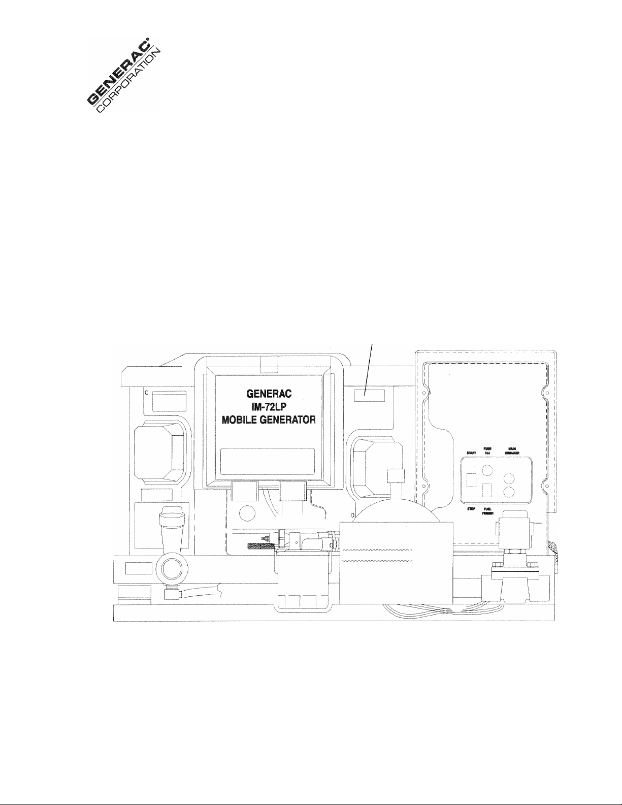
IDENTIFI
CATION
RECORD
Please record the following information from the generator DATA DECAL or information decal.
1. Model Number
3. kW Rating.
________________________
2. Serial Number
4. Rated Voltage.
Data Decal
Industrial Mobile Generator
3
Page 4

Generac IM-72LP Industrial Mobile Generator
SAFETY RULES
..................................
IDENTIFICATION RECORD
TABLE OF CONTENTS
...
.........2
...........................
.....3
.................................
4
Fuel Requirements...
Engine Oil Requirements
Engine Specifications.......
Generator Specifications
.......................................................11
READ THIS MANUAL THOROUGHLY
Operation and Maintenance..............
.............................
How to Obtain Service.....................................................5
..5
MAINTENANCE
Checking Engine Oil Level.
Change Engine Oil........................................................
GENERATOR FAMILIARIZATION
Generator Applicability
Installation
..........
................................................
6
..................................................... 6
Safety......................................................................... 6
Generator AC Connection System
OPERATION
Operating Precautions
Generator Control Panel
.......
...
............................
.6-7
................................................................................................................
...........................................
7
Optional Remote Start/Stop Panel........................................................................................
Before Starting the Engine
.............................................
..8
Starting the Generator............................................... 8-9
Stopping the Generator
25 Hour Break-In Period
25 Hour Check-Up Period
Attention Required After Submersion
Effects of Moisture and Dirt
Automatic Low Oil Pressure Shutdown.......................
High Oil Temperature Shutdown
Field Boost..............................................................
Over Voltage Protection
Engine Governed Speed ...........................................
.....
..............................................
...
...............................................
.........................
.......................
..............................
..............
....
............................9
9-10
..................................
.......
.................................................
9
9
9
9
10
10
10
....10
Change Oil Filter
Engine Air Cleaner
........................................................
....................................................
Clean Air Intake Screen
Engine Spark Plug
.......................................
Spark Arrestor Muffler
Cleaning the Generator
Battery
........................................................................
Major Service Manual
Drive Belt
.......................................................................15
Exercising the Generator..
Out of Service Protection
Return the Unit to Service after Storage
TROUBLESHOOTING........................................................16
ELECTRICAL
REPAIR PARTS..........................................................18-29
CALIFORNIA EMISSION STATEMENT ....................30-31
WARRANTY .......................
...
............................................
..........................................
..........................................
...........................................
11
....11
11
..12
12
12-13
13
.....
.............................................
.............
...................................................
...........................................
7
.......
..................................................................................................
13
13-14
14
14
14
.7
...............................................15
.........................................
.......................
.................................
.15
15
back cover
SPECIFICATIONS
Industrial Mobile Generator
Page 5

READ
THIS
MANUAL
Generac 1M-72LP Industrial Mobile Generator
READ THIS MANUAL THOROUGHLY
If you don't understand any portion of this manual, contact Gen
erac for a demonstration of actual starting, operating and
servicing procedures.
Throughout this publication and on tags and decals affixed to
the generator, DANGER and CAUTION blocks are used to alert
you to special instructions about a particular operation that may
be hazardous if performed incorrectly or carelessly. Observe
them carefully.
These safety warnings cannot eliminate the hazards that they
indicate. Strict compliance with the special instructions while
performing the service plus “common sense” are major mea
sures to prevent accidents.
The following definitions apply to DANGER, CAUTION and
NOTE blocks found throughout the manual.
DANGER: Indicates an immediately hazardous sit
uation which, if not avoided, will result in death or
serious injury. Danger is limited to the most
extreme situations.
WARNING: Indicates a potentially hazardous situ
ation which if not avoided, could result in death or
serious injury.
CAUTION: Indicates a potentially hazardous situa
tion which, if not avoided, may result in minor or
moderate injury. Caution may also be used to alert
against unsafe practices.
NOTE: After this heading you can read explanatory statements
that require special emphasis.
These symbols indicate the following:
Points out important safety information and, if not fol
lowed, could endanger personal safety and/or property
of yourself and others.
The operator (driver) is responsible for proper and safe use
of the vehicle, equipment on the vehicle, and the safety of all
vehicle occupants. We strongly recommend that the opera
tor read this Owner’s Manual and thoroughly understand ^11
instructions before using this equipment. We also strongly rec
ommend instructing other occupants in the vehicle to properly
start and operate the generator. This prepares them if they
need to operate the equipment in an emergency.
OPERATION AND MAINTENANCE
It is the operator's responsibility to perform all safety checks;
to make sure that all maintenance for safe operation is per
formed promptly: and to have the equipment checked by an
Authorized Dealer periodically. Normal maintenance service
and replacement of parts are the responsibility of the
Owner/Operator and, as such, are not considered defects in
materials or workmanship within the terms of the warranty. Indi
vidual operating habits and usage contribute to the need for
maintenance service.
Proper maintenance and care of your Industrial Mobile Gen
erator assures a minimum number of problems and keeps your
operating expenses at a minimum. See your authorized
Dealer/Distributor for service aids and accessories.
HOW TO OBTAIN SERVICE
When your Industrial Mobile Generator set requires servicing
or repairs, simply contact an Authorized Service Facility for
assistance. Service technicians are factory-trained and are
capable of handling ail of your service needs.
When contacting an Authorized Service Facility or the factory
about parts and service, always supply the complete model
number and serial number of your unit as given on its data
decal.
The warranty on your generator is included in the Owner’s
Manual, as well as listings for repair parts.
Potential explosion hazard.
Potential fire hazard.
A
Potential electrical shock hazard.
A
ndustrial Mobile Generator
Page 6
GENERÄL
INFORMATION
Generac 1M-72LP Industrial Mobile Generator
GENERATOR APPLICABILITY
These generators have been designed and manufactured for
supplying electrical power for recreational vehicles. You should
not modify the generator or use it for any application other than
for what it was designed. If there are any questions pertain
ing to its application, write or call the factory. Do not use the
unit until you have been advised by a competent authority.
DANGER: FOR FIRE SAFETY, THE GENERATOR
MUST HAVE BEEN PROPERLY INSTALLED IN
A
COfyiPLIANCE WITH INDUSTRY STANDARDS. THE
GENERATOR ALSO MUST HAVE BEEN INSTALLED
IN STRICT COMPLIANCE WITH THE MANUFAC
TURER’S DETAILED INSTALLATION
INSTRUCTIONS. AFTER INSTALLATION, DO
NOTHING THAT MIGHT RENDER THE UNIT IN
NON-COMPLIANCE WITH SUCH CODES, STAN
DARDS AND INSTRUCTIONS.
You can use this generator to supply electrical power for oper
ating 120/240 volts, single phase, 60 Hertz, AC electrical
loads requiring the following:
Industrial
Generator
IM-72LP 7200 60
CAUTION: Do not overload the generator. Some
installations may require that electrical loads be
alternated to avoid overloading. Applying exces
sively high electrical loads may damage the
generator and may shorten its life. Add up the
rated watts of all electrical lighting, appliance, tool
and motor loads the generator will power at one
time. This total should not be greater than the
wattage capacity of the generator, if an electrical
device nameplate gives only volts and amps, multi
ply volts times amps to obtain watts (volts x amps
= watts). Some electric motors require more watts
of power (or amps of current) for starting than for
continuous operation.
Power
(wattage)
Amps at
120 Volts
Amps at
240 Volts
30
INSTALLATION
This Owner’s Manual has been prepared under the assump
tion that a competent, qualified technician installed the
generator into an industrial vehicle. We also assume the
installer complied with all applicable codes, standards and reg
ulations pertaining to installation.
Owners/Operators should make sure nothing is done during
installation that might render the unit unsafe or in noncompli
ance with applicable codes, standards and instructions. They
should be sure the unit has been installed to allow adequate
ventilation for cooling and exhaust air.
SAFETY
Before using the generator set, carefully read GENERAL
SAFETY RULES inside the cover. Comply with these RULES
to prevent accidents and damage to equipment and/or prop
erty. Generac suggests copying and posting the GENERAL
SAFETY RULES in potential hazard areas of the generator.
Safety should be stressed to all operators of this equipment.
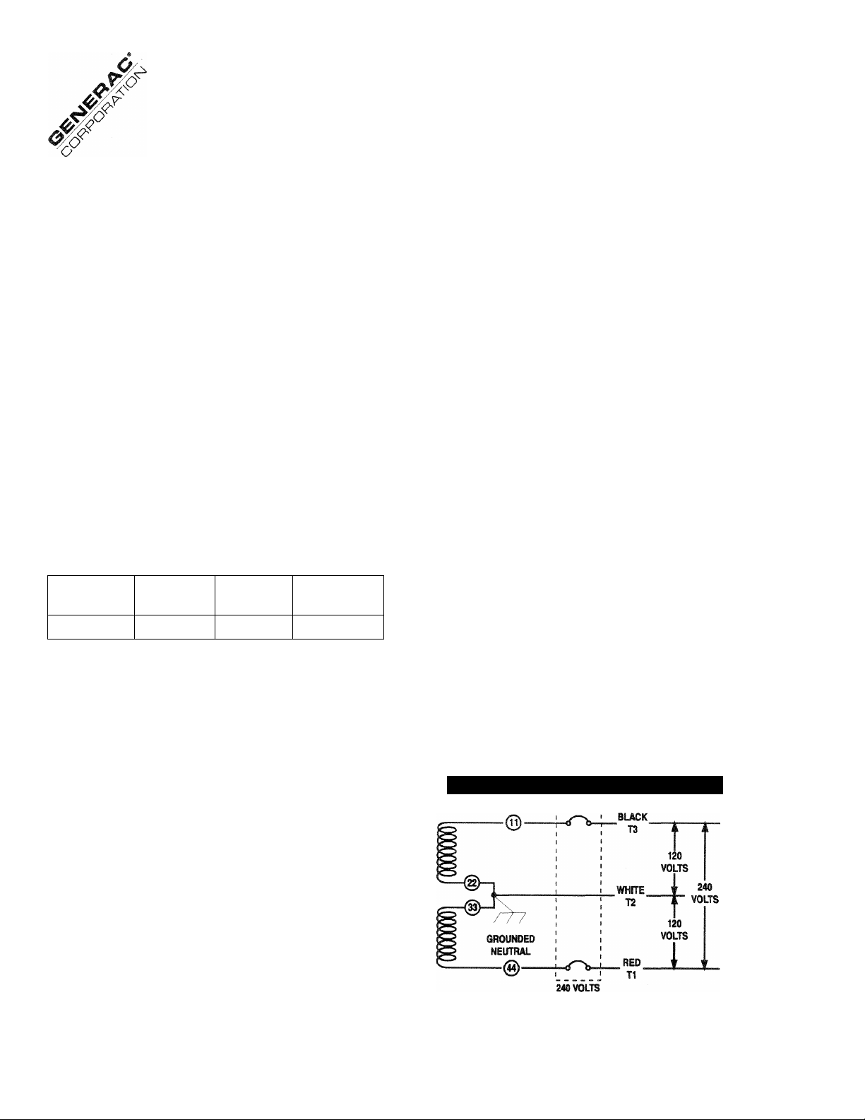
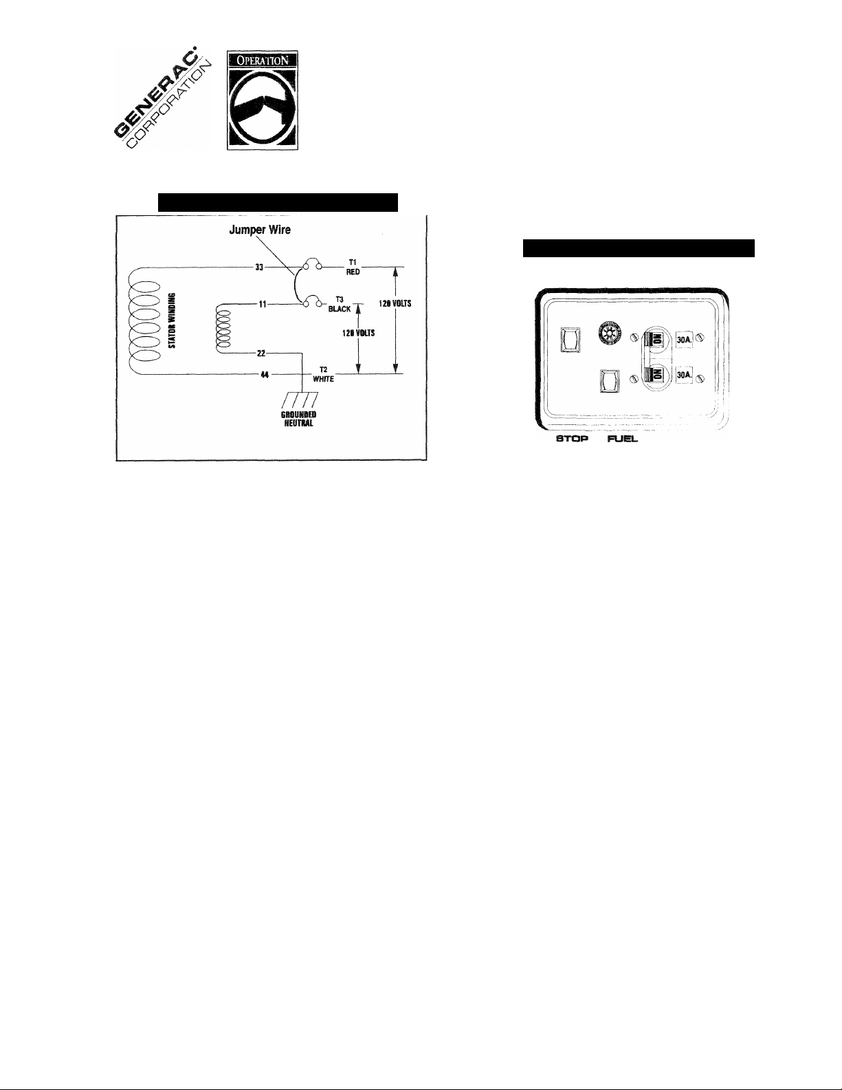
GENERATOR AC CONNEQION
SYSTEM
This generator set is equipped with dual Stator AC power
windings. These two stator windings supply electrical power
to customer electrical loads by means of a dual 2-wire con
nection system. Note, however, that neutral is grounded.
The generator may have been installed so that units power
120/240 volts AC loads (Figure 1); or you can wire them to
connect only 120 volts AC electrical loads (Figure 2). Be sure
to install jumper wire between the circuit breakers and remove
bar in ciricuit breaker set (Figure 2) when reconnecting for 120
volts.
Figure 1 — Connections for 120/240 Volts
Industrial Mobile Generator
6
CIRCUrr BREAKER
Page 7
Generac IM-72LP Industria! Mobile Generator
Figure 2 — Connections for 120 Volts
GENERATOR CONTROL PANEL -
Mounted on the generator control panel (Figure 3) are the fol
lowing features:
Figure 3 — Generator Control Panel
'tGA
PUSE MAIN
BREAKER
Fulvio?
STAFIT
OPERATING PRECAUTIONS
WARNING: NEVER OPERATE THE GENERATOR
SET WHILE THE VEHICLE IS PARKED OVER DRY
A
LEAVES, DRY GRASS OR ANY OTHER COM
BUSTIBLE SUBSTANCE. THE GENERATORS
EXHAUST SYSTEM BECOMES EXTREMELY HOT
AND CAN CAUSE FIRE IF IT IS TOO CLOSE TO
COMBUSTIBLE MATERIALS.
WARNING: THE GENERATORS EXHAUST
SYSTEM GIVES OFF DEADLY CARBON MONOX
IDE GAS. THIS DANGEROUS GAS, IF BREATHED
IN SUFFICIENT CONCENTRATIONS CAN CAUSE
UNCONSCIOUSNESS AND EVEN DEATH. NEVER
OPERATE THE GENERATOR SET WITH THE VEHI
CLE INSIDE ANY GARAGE OR OTHER ENCLOSED
AREA. NEVER OPERATE THE GENERATOR WITH
A LEAKING EXHAUST SYSTEM. CLOSE WIN
DOWS IN THE VICINITY OF THE GENERATOR
EXHAUST OUTLET AND TAKE ANY OTHER STEPS
THAT MAY BE NECESSARY TO PREVENT
EXHAUST GASES FROM ENTERING ROOMS OR
AREAS OCCUPIED BY PEOPLE OR ANIMALS.
FUEL PRIMER
Before starting a cold engine (it has not been started in more
than two weeks), you must press this switch to bring fuel from
the tank to the fuel pump. This rocker type switch springs back
into its original position when you release it.
START/STOP SWITCH
To crank and start the engine, hold this switch at its START
position. Release the switch when the engine starts. To stop
an operating engine, press and hold the switch in its STOP
position until the engine shuts off. The switch center position
is the RUN position.
FUSE
Protects the engine DC control circuit against electrical over
load. If the fuse element has melted open due to overloading,
the engine cannot be cranked. If you must replace it, use only
an identical replacement fuse.
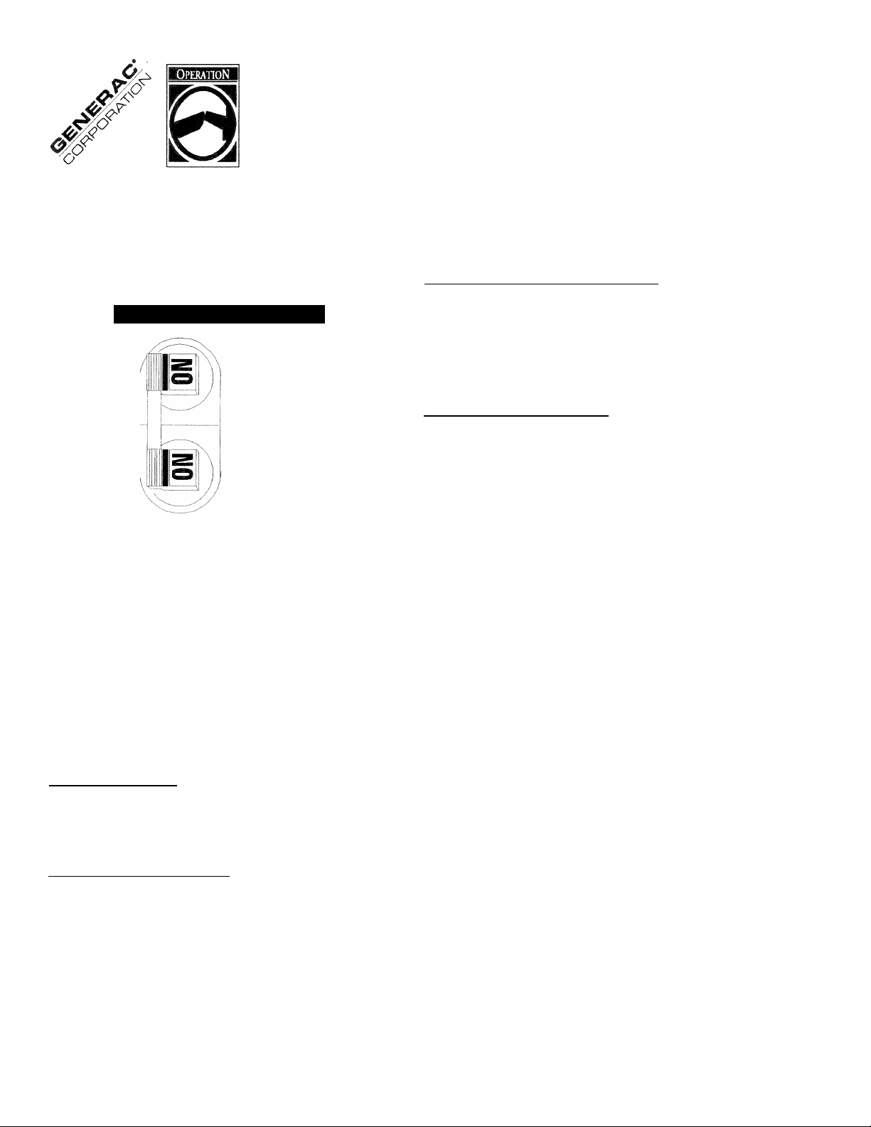
MAIN BREAKER
Protects generators AC output circuit against overload and pro
vides a method of turning CFF the generators 120/240 volts
AC output to vehicle circuits (Figure 4).
Industrial Mobile Generator
7
Page 8
Generac IM-72LP Industrial Mobile Generator
NOTE: Refer to THE GENERATOR AC CONNECTION
SYSTEM on page 4. Individual installations will differ. If an
overload occurs, the dual breaker will open the hot stator
leads (11 and 44). When the generator has been connected
for 120 volts only, either of the dual circuit breakers will open
stator AC output leads No. 11 and No. 33.
Figure 4 — Dual Circuit Breaker
30A.
30A.
OPTIONAL REMOTE
START/STOP PANEL
A remote mounted Start/Stop Panel is available, which allows
you to start and stop the generator engine conveniently from
inside the vehicle.
BEFORE STARTINC THE ENGINE
IMPORTANT: INSTRUCTIONS AND INFORMATION IN THIS
MANUAL ASSUME THE GENERATOR HAS BEEN PROP
ERLY INSTALLED, CONNECTED, SERVICED, TESTED AND
ADJUSTED BY A QUALIFIED INSTALLATION TECHNICIAN
OF INSTALLATION CONTRACTOR.
■ INSTALLATION
Generator installation must have been properly completed so
it complies with all applicable codes, standards and regula
tions and with the manufacturer's recommendations.
■ ENGINE LUBRiCATIQN__________________
Have engine crankcase properly serviced with recommended
oil before starting. Refer to "Maintenance" and "Specifica
tions" sections for oil servicing procedures and
recommendations.
CAUTION: Any attempt to crank or start the
engine before you have properly serviced it with
the recommended oil may result in engine failure.
___________
____
FUEL SUPPLY
The engine must have adequate supply of proper fuel to oper
ate. Before starting, check that sufficient fuel is available.
■ COOLING AND VENTILATING AIR
Air inlet and outlet openings in the generator compartment
must be open and unobstructed for continued proper operation.
Without sufficient cooling and ventilating air flow, the enginegenerator quickly overheats, which causes it to quickly shutdown.
Overheating could also damage the unit or your vehicle.
m ENGINE EXHAUST GAS
Before starting the generator engine, you should be sure there
is no way for exhaust gases to enter the vehicle interior and
endangering people or animals. Close windows, doors and
other openings in the vehicle that, if open, might permit exhaust
gases to enter the vehicle.
DANGER: THE GENERATOR ENGINE GIVES OFF
DEADLY CARBON MONOXIDE GAS THROUGH ITS
EXHAUST SYSTEM. THIS DANGEROUS GAS, IF
BREATHED IN SUFFICIENT CONCENTRATIONS,
CAN CAUSE UNCONSCIOUSNESS OR EVEN
DEATH. DO NOT OPERATE THE GENERATOR IF
ITS EXHAUST SYSTEM IS LEAKING OR HAS BEEN
DAMAGED. SYMPTOMS OF CARBON MONOXIDE
POISONING ARE (A) INABILITY TO THINK COHER
ENTLY,
(D) THROBBING TEMPLES, (E) DIZZINESS, (F)
HEADACHE, (G) WEAKNESS AND SLEEPINESS. IF
YOU FEEL ANY OF THESE SYMPTOMS, MOVE
INTO FRESH AIR IMMEDIATELY. IF SYMPTOMS
PERSIST, GET MEDICAL HELP.
STARTING THE GENERATOR
To start the generator from either the generator control panel
or from the optional Remote Panel, proceed as follows:
1. Turn OFF electrical loads, using whatever means provided
in your vehicle (such as a main line circuit breaker or trans
fer switch.
NOTE: If starting from the generator panel, turn OFF loads
by setting the generators main circuit breaker to “OFP or
“OPEN”. If starting from a Remote Panel, turn OFF loads using
whatever means is provided in the vehicle (such as a main cir
cuit breaker).
(B) VOMITING, (C) TWITCHING MUSCLES,
Industrial Mobile Generator
Page 9

Generac IM-72LP Industria! Mobile Generator
2. If you have not started the engine in more that two weeks,
press the Fuel Pump Primer switch and hold it for about 30
seconds to activate the automatic shut-off function. How
ever, if the engine is warm, skip step 2.
3. To crank and start the engine, hold the start/stop switch at
START. Release the switch when the engine starts.
CAUTION: If the engine does not start after it has
been cranking for 15 seconds, release the
start/stop switch and try again. Holding the switch
for longer than 15 seconds can damage the starter
motor.
4. Let the engine run at no-load for a few minutes to stabilize
and warm up the engine.
5. Turn ON electrical loads, using whatever means provided
(such as a main circuit breaker or transfer switch).
STOPPING THE GENERATOR
1. Turn OFF all electrical loads, using whatever means pro
vided (such a main circuit breaker or transfer switch).
2. Place start/stop switch in its STOP position.
25 HOUR BREAK-IN PERIOD
The first 25 hours of operation is the break-in period for the
generator. Properly breaking in the generator is essential to
reducing oil consumption and enhancing engine performance.
During the break-in period, observe the following rules:
• For the first 25 hours, run the generator at varying electri
cal loads, to help set the engine piston rings properly.
• Following the initial 25 hour break-in period, avoid light elec
trical loads for the next 75 hours of operation. The unit should
be loaded at 50% (or more) of its capacity during those 75
hours. Repeated light loads during break-in period may
improperly seat the piston rings, resulting in blowby and high
oil consumption.
• Check oil level frequently during the break-in period. Add
oil if needed. It is natural for the generator engine to con
sume more oil than is normal until the piston rings have
seated properly.
• When the 25 hour break-in period is done, complete the
tasks recommended under 25 HOUR CHECK-UP PERIOD.
25 HOUR CHECK-UP PERIOD
After the first 25 hours of operation have been completed, con
tact an Authorized Service Facility for the following
maintenance. The Owner/Operator is responsible for any
changes.
• Change engine crankcase oil and oil filter.
• Check all cooling system ventilation openings on the vehi
cle.
• Check engine ignition system.
• Inspect the entire electrical system.
• Inspect the engine exhaust system.
AHENTION REQUIRED AFTER
SUBMERSION
if the generator has been submerged in water, it must NOT
be started or operated. Following any submersion in water,
have an authorized Generac Service Facility thoroughly clean
and dry the generator.
EFFECTS OF MOISTURE AND DIRT
Keep the generator set as clean and dry as possible. Protect
unit against excessive dust, dirt, corrosive vapors, road splash,
etc. Permitting dirt and moisture to accumulate on generator
windings will have an adverse effect on the insulation resis
tance of those windings.
When moisture is allowed to remain in contact with windings,
some of the moisture will be retained in voids and cracks in
the insulation. This causes a reduced insulation resistance and
will eventually cause problems. Dirt will make the problem
worse, since dirt tends to hold moisture in contact with wind
ings. Salt (as from sea air) will also worsen the problem since
it tends to absorb moisture from the air. Salt and moisture, when
combined, form a good electrical conductor.
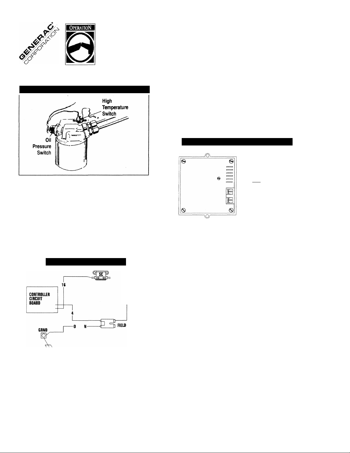
AUTOMATIC LOW OIL PRESSURE
SHUTDOWN
The engine is equipped with a normally-closed (N.C.) oil pres
sure switch (Figure 5). Engine oil pressure holds the switch
open during cranking and operation. Should oil pressure drop
below about 8-10 psi, the switch contacts close and the engine
automatically shuts down.
Industrial Mobile Generator
9
Page 10
Generac IM-72LP Industrial Mobile Generator
Figure 5 — Oil Pressure and Temperature Switches
HIGH TEMPERATURE SHUTDOWN
Temperature switch (Figure 5) with normally-open (N.O.) con
tacts is mounted on the engine. Should engine temperature
exceed about 284° F (140°C), the switch contacts close and
the engine shuts down.
OVER VOLTAGE PROTEQION
A solid state voltage regulator (Figure 7) controls the gener
ators AC output voltage. This regulator supplies an excitation
current to the rotor. By regulating the rotor’s excitation cur
rent, the strength of its magnetic field is regulated and, in
turn, the voltage delivered to connected electrical loads is
controlled. When the AC frequency is 60 Hz, voltage is reg
ulated at 120 volts (voltage-to-frequency ratio is 2-to-1).
Figure 7 — Solid State Voltage Regulator
^^[¿"Zh-SENSIIIG
CZ3=^4(+K TO BOTOI
i=3=-i{-b-^(iiœCT CURRENT)
----
—EXCITATION WniOING
ЬЕЙВИ STATOR
(ALTERNATING CURRENT)
FIELD BOOST
The controller Circuit Board houses a field boost diode and
resistor. These two components are part of a “field boost” cir
cuit (Figure 6).
Figure 6 — Field Boost Circuit
CLOSEST TO
BEARING
During engine cranking only, a positive DC (battery) voltage
is delivered through the diode, resistor, brushes and slip rings,
and to the generator rotor. Application of this voltage to the
rotor Hashes the field” whenever it is started. Flashing of the
field each time the generator starts makes sure that a suffi
ciently strong magnetic field is available to produce the required
“pick up” voltage in the stator windings.
The voltage regulator also incorporates a “voltage surge pro
tection circuit.” This circuit prevents troublesome surges in the
generator AC output voltage. Voltage surge is a common
cause of damage to electronic equipment.
ENGINE GOVERNED SPEED
The generator is equipped with a 2-pole revolving field (rotor)
which must be driven at 3600 rpm to produce the unit’s rated
AC frequency of 60 Hz. The gas engine governor was factory
set to about 62 Hz (2900 RPM) at no-load. After installing it,
the technician should check and adjust the governed speed.
Setting no-load frequency slightly high helps prevent exces
sive frequency, rpm and voltage droop under heavy electrical
loading.
DANGER: DO NOT TAMPER WITH THE ENGINE GOV
ERNOR SETTINGS. EXCESSIVELY HIGH ENGINE
SPEEDS ARE DANGEROUS AND INCREASE THE
RISK OF PERSONAL INJURY AND DAMAGE TO
EQUIPMENT AND/OR PROPERTY. EXCESSIVELY
LOW SPEEDS IMPOSE A HEAVY LOAD ON THE
ENGINE WHEN ADEQUATE ENGINE POWER IS NOT
AVAILABLE AND MAY SHORTEN ENGINE LIFE. THE
GENERATOR SUPPLIES CORRECT RATED FRE
QUENCY AND VOLTAGE ONLY AT THE PROPER
SPEED. SOME ELECTRICAL DEVICES MAY BE DAM
AGED BY INCORRECT FREQUENCY AND/OR
VOLTAGE. IF ENGINE SPEED APPEARS TO BE
INCORRECT, CONTACT YOUR NEAREST AUTHO
RIZED SERVICE FACILITY.
industrial Mobile Generator
10
Page 11

Generac 1M-72LP Industria! Mobile Generator
FUEL REQUIREMENTS
This generator is equipped with a liquid propane (LP) gas fuel
system. LP gas is usually supplied as a liquid in pressure tanks
(Figure 8).
The IM series generators require a “vapor withdrawal” type fuel
system. This type of gaseous fuel system uses the vapors
forming above the liquid fuel in the storage tank. Air temper
atures around the storage tank must be high enough to sustain
adequate fuel vaporization. In colder climates, you may need
to use an independent heat source to be sure the fuel suffi
ciently vaporizes in the storage tank.
LP gas may consist of propane, butane, or a mixture of the
two gases. Propane vaporizes at temperatures as low as -
20°F (-29°C), but butane returns to its liquid state when the
temperature drops below about 32°F (0°C). For that reason,
a higher ratio of propane is desired in the gas mixture when
temperatures drop below freezing.
ENGINE OIL REQUIREMENTS
Use a high quality detergent oil classified “For Service SF and
with an oil viscosity rating of SAE10W-30 oil. Do not pour in
any additives to the recommended oil. Engine crankcase
capacity is 1.5 U.S. quarts. See MAINTENANCE section for
oil level check and filling procedures.
Figure 8 — Typical LP Gas Fuel System
ENGINE SPECIFICATIONS
Type of Engine
Cooling Method.
Rated Horsepower
Displacement......................................................
Compression Ratio
Cylinder Block.......................Aluminum with cast iron sleeve
Type of Governor
Engine Governed Speed ..............
Air Cleaner
.
................................................................. foam pre-cleaner
Starter...
Ignition System
Recommended Spark Plugs ..................Champion RC12YC
Spark Plug Gap
..................................................Twin Cylinder
...................................
...
................
.............
...
.......................
.......................................
.............
........................
..........
..........
.........................................
......
Solid state with flywheel magneto
.....
.................
......................
..................
16 at 3600 rpm
..Mechanical, fixed speed
......................
......
Paper element with
..........
.....
12 volt DC electric
0.030 inch (0.76mm)
Air-cooled
479.4cc
8.6 to1
..2900 RPM
GENERATOR SPECIFICATIONS
Rotor RPM
Rotor Poles
Engine RPM ...................................................................2900
Wattage*..........................................................................7200
.....................................................................
.......................................................................
3600
2
Voltage*.............................................................................240
Current*.............................................................30 AC ampsV
Phase ................................................................................
Frequency..................................................................
Weight...................................................................200 pounds
Length
.................................................................
Width
..................................
All units are reconnectable to 120 volts, single phase volt
age output.
V Rated maximum continuous current 120 volts is 60 amps.
11
..............
...............
...25 inches
.....
18.5 inches
1
60 Hertz
Page 12

Generac IM-72LP Industrial Mobile Generator
MAINTENANCE
This section includes information about simple maintenance
which includes the following tasks:
• Checking engine oil level.
• Changing engine oil.
• Changing oil filter.
• Servicing the air cleaner.
• Cleaning the air intake screen.
• Cleaning spark plugs.
CHECKING ENGINE OIL LEVEL
Check engine crankcase oil level at least every eight hours of
operation, or before each use (Figure 9).
• Be sure the generator is as level as possible.
• Remove oil dipstick and wipe dry with clean, lint-free cloth.
• Install and tighten oil dipstick, then remove again.
• Oil should be at dipstick FULL mark. If necessary, add the
recommended oil to the FULL mark only. DO NOT FILL
ABOVE “FULL” MARK.
• Install and tighten oil dipstick cap before operating the
engine.
NOTE: See “Engine Oil Requirements” on Page 11 for rec
ommended oils.
CHANGE ENGINE OIL
Change engine oil after the first 25 hours of operation (after
the 25 hour break-in period, Page 9). Thereafter, change oil
every 100 operating hours. Change oil more frequently if oper
ating consistently under heavy load or at high ambient
temperatures.
• Warm up engine for at least five minutes, then shut down.
• With engine still warm from running, remove cap from oil
drain hose (Figure 10). Drain oil completely into a suitable
container.
• When oil has drained, install and tighten drain hose cap.
• Remove oil dipstick and fill crankcase with the recom
mended oil (See Page 11). The engine crankcase can hold
about 1.5 quarts. DO NOT FILL ABOVE “FULL” MARK.
• Install and tighten dipstick cap before operating engine.
Figure 10 — Oil Drain Hose and Cap
Figure 9 — Oil Dipstick and Fill Tube
CHANGE OIL FILTER
Replace the engine oil filter after the first 25 hours of opera
tion, every 200 operating hours thereafter.
• Turn oil filter counterclockwise to remove (Figure 11).
• Coat gasket of new filter with engine oil.
• Turn new filter clockwise until its gasket contacts lightly with
the filter adapter. Then tighten with an additional 3/4 to one
turn by hand.
• Run engine and check for leaks.
Industrial Mobile Generator
12
Page 13

Generac 1M-72LP Industria! Mobile Generator
NOTE: Check oil level and fill to full mark after checking for
leaks. Filter will retain some oil.
Figure 11 — Engine Oil Filter
Figure 12 — Engine Air Cleaner
ENGINE AIR CLEANER
Clean and re-oil the foam pre-cleaner every three months or
ever 25 hours of operation, whichever occurs first. Service
the foam pre-cleaner more frequently if you operate the gen
erator in extremely dusty or dirty conditions (Figure 12):
• Turn KNOB counterclockwise to loosen.
• Remove COVER, FOAM PRE-CLEANER and PAPER
FILTER.
• Remove foam pre-cleaner from cover
• Wash foam pre-cleaner in liquid detergent and water.
• Wrap foam pre-cleaner in a cloth and squeeze dry.
• Saturate foam pre-cleaner in engine oil. Squeeze to remove
excess oil and to distribute oil.
• Install foam pre-cleaner into cover, followed by paper filter.
Tabs at edges of paper filter must lock into slots on cover.
Once each year or every 100 operating hours (whichever
comes first), replace the paper filter. The new replacement
filter must be a flame retardent type.
CLEAN AIR INTAKE SCREEN
Clean ail foreign material from the air intake screen (Figure
13) at lease once every 100 hours of operation. Clean more
often if necessary.
Inspect the area around the generator exhaust muffler peri
odically and remove all grass, leaves, dirt, etc. from this area.
Figure 13 — Cleaning Air Intake Screen
ENGINE SPARK PLUGS
Clean engine spark plugs and set gap to 0.030 inch (0.76mm)
every 100 hours of operation (Figure 14). Clean by scraping
or wire brushing and washing with commercial solvent. DO
NOT BLAST CLEAN SPARK PLUGS.
n d u s t r i a I Mobile Generator
13
Page 14

Generac IM-72LP Industrial Mobile Generator
CAUTION: Sparking can occur if wire terminal
does not fit firmly over spark plug terminal end. If
necessary, reform wire terminal to obtain a tight fit.
Figure 14 — Engine Spark Plug
SPARK ARRESTOR MUFFLER
If the generator is not equipped with a spark arrestor exhaust
muffler and is to be used on any forest covered, brush cov
ered or grass covered unimproved land, you may have to
install a spark arrestor. The spark arrestor must be maintained
in effective working order by the vehicle owner/operator.
For assistance in ordering, installing and maintaining spark
arrestor exhaust mufflers, contact your nearest authorized
service facility.
Exhaust mufflers supplied by Generac are spark arrestor
types. Generac exhaust mufflers for IM generators do not have
a spark arrestor screen, but are of the more efficient loriod”
or “swirl” type. To remove carbon and combustion deposits
from such mufflers, remove the PLUG from muffler and run
engine for about 15 minutes. Shut engine down, let the muf
fler cool and install the plug.
WARNING: BE SURE TO RE-INSTALL THE PLUG
FROM THE MUFFLER TIGHTLY. ENGINE VIBRA
A
TION COULD CAUSE A LOOSE PLUG TO FALL
OUT. WITHOUT THE PLUG IN PLACE, HOT
ENGINE EXHAUST IS DIRECTED OUT THE OPEN
ING. THIS HOT EXHAUST, DEPENDING ON THE
INSTALLATION, COULD BE DIRECTED TO AREAS
NOT ABLE TO WITHSTAND THE EXTREME HEAT
SUCH AS WOODEN FLOOR BOARDS OR OTHER
FLAMMABLE MATERIAL THIS COULD RESULT IN
A FIRE.
CLEANING THE GENERATOR
Keep your generator set as clean and dry as possible. Dirt and
moisture that are permitted to accumulate on electrical wind
ings have an adverse affect on the insulation resistance of those
windings.
Moisture that is allowed to remain in contact with windings will
be retained in voids and cracks of the windings. Dirt makes
the problem worse, since it tends to hold the moisture into con
tact with the windings. Sait, as from sea air, worsens the
problem since it tends to absorb moisture from the air. The
combination of salt and moisture makes a good electrical
conductor.
CAUTION! Do NOT use a forceful spray of water to
clean the generator. Water will enter the generator
interior and cause problems, and may also conta
minate the generator fuel system.
BAHERY
All lead-acid storage batteries will discharge when not in use.
Inspect the generator battery as follows:
■ ONCE WEEKLY
Inspect battery posts and cables for tightness, corrosion.
Clean and/or tighten as necessary.
Also check battery fluid level, and, if necessary, fill with DIS
TILLED WATER ONLY. DO NOT USE TAP WATER IN
BATTERY.
m E¥ERY SIX MONTHS
Have the battery state of charge and condition checked by an
automotive service facility. This should be done with an auto
motive type battery hydrometer.
DANGER: STORAGE BAHERIES GIVE OFF
EXPLOSIVE HYDROGEN GAS. THIS GAS CAN
FORM AN EXPLOSIVE MIXTURE AROUND THE
BATTERY FOR SEVERAL HOURS AFTER CHARG
ING. THE SLIGHTEST SPARK CAN IGNITE THE
GAS AND CAUSE AN EXPLOSION. SUCH AN
EXPLOSION CAN SHAHER THE BAHERY AND
CAUSE BLINDNESS OR OTHER INJURY. ANY
AREA THAT HOUSES A STORAGE BAHERY
MUST BE PROPERLY VENTILATED. DO NOT
ALLOW SMOKING, OPEN FLAME, SPARKS OR
ANY SPARK PRODUCING TOOLS OR EQUIPMENT
NEAR THE BATTERY.
Industrial Mobile Generator
14
Page 15

Generac IM-72LP Industrial Mobile Generator
DANGER: BAHERY ELECTROLYTE FLUID
IS AN EXTREMELY CAUSTIC SULFURIC ACID
SOLUTION THAT CAN CAUSE SEVERE BURNS.
DO NOT PERMIT FLUID TO CONTACT EYES, SKIN,
CLOTHING, PAINTED SURFACES, ETC. WEAR
PROTECTIVE GOGGLES, PROTECTIVE CLOTHING
AND GLOVES WHEN HANDLING A BAHERY. IF
YOU SPILL THE FLUID, FLUSH THE AFFECTED
AREA IMMEDIATELY WITH CLEAR WATER.
DANGER: DO NOT USE ANY JUMPER CABLES
OR BOOSTER BAHERY TO CRANK AND START
THE GENERATOR ENGINE. IF ANY BAHERY HAS
DISCHARGED, REMOVE IT FROM THE VEHICLE
FOR RECHARGING.
MAJOR SERVICE MANUAL
To obtain a service manual for your generator, order it from
your dealer/distributor or contact the factory. Be sure to iden
tify your unit’s MODEL NUMBER and SERIAL NUMBER.
DRIVE BELT
The engine drives the generator rotor by means of a pulley
and drive belt arrangement. The drive belt and pulleys are
warranted for the life of the generator. Drive belt tension was
properly adjusted before the unit was shipped form the fac
tory. If you suspect that drive belt tension is incorrect, contact
an autorized service facility.
EXERCISING THE GENERATOR
Generac recommends that you start and operate the gener
ator at least once every seven days. Let the unit run for at
least 30 minutes to “exercise” the engine.
OUT OF SERVICE PROTEQION
If you cannot exercise the generator every seven days and it
is to be out of service longer than 30 days, prepare the gen
erator for storage as follows;
• Start the engine and let it warm up.
• While the engine is still warm from running, drain the oil com
pletely. Refill crankcase with recommended oil. See
“Specifications.”
• Attach a tag to the engine indicating the viscosity and clas
sification of the oil in the crankcase.
• Remove spark plugs and add about 1/2 ounce (15ml) of
clean, fresh engine oil into spark plug threaded openings.
Crank engine several times to distribute oil, then install and
tighten spark plugs.
• Remove the battery and store in a cool, dry room on a
wooden board. Never store the battery on any concrete or
earthen floor.
• Clean and wipe the entire generator.
RETURN UNIT TO SERVICE
AFTER STORAGE
To return the unit to service after storage, proceed as follows:
• Check tag on engine for oil viscosity and classification.
Verify that the correct recommended oil is used in engine.
If necessary, drain and refill with proper oil.
• Check battery. Fill all cells to the proper level with distilled
water. DO NOT USE TAP WATER IN THE BATTERY.
Recharge battery to 100% state of charge, or, if defective,
replace the battery.
• Press the Fuel Pump Primer switch and hold it for about 30
seconds to activate the automatic shut-off function.
• Turn OFF all electrical loads, then start the engine.
• Let engine warm up.
• Apply electrical loads to at least 50% of the unit’s rated
wattage capacity.
• When engine is thoroughly warmed up, shut it down.
THE GENERATOR IS NOW READY FOR SERVICE.
Industrial Mobile Generator
15
Page 16

Generac IM-72LP Industrial Mobile Generator
w
TROUBLESHOOTING POINTS
PROBLEM
Engine won’t crank. 1. 15 amp fuse blown. 1.
Engine cranks but won't start.
Engine starts hard, runs rough.
Engine starts, then shuts down.
Start/Stop switch at Stop, engine
continues to run.
CAUSE CORREaiON
2. Loose or corroded or defective
battery cables.
3. Defective engine Start/Stop switch. 3.
4. Defective starter contactor.
5. Defective starter motor.
6. Low Battery Voltage.
1. Out of fuel.
2, Fuel shutoff solenoid is defective. 2.
3. Open Wire #14 from Eng. Control Board.
4. Spark plugs defective.
1. Air cleaner plugged or damaged. 1.
2. Defective spark plugs. 2.
1. Engine oil level is low.
2. Engine is overheated.
3. Defective Low Oil Pressure System.
4. Defective Engine Control Board.
1. Defective Start/Stop switch.
2. Open disconnect wire #18 between
Start/Stop switch and Engine Control.
3. Open/disconnected wire #0 between
Start/Stop switch & Engine Control Board.
4. Defective Engine Control Board.
Replace fuse.
2.
Tighten, clean or replace
as necessary.
Replace Start/Stop switch.
4.
Replace starter contactor.
5.
Replace starter motor
6.
Charge or replace battery.
1.
Replenish fuel.
Replace fuel shutoff solenoid.
3.
Reconnect wire.
4.
Clean, regap or replace plugs.
Clean or replace as needed.
Clean, regap or replace plugs.
1.
Check oil and add as needed.
2.
Check adequate ventiliation.
3.
Have serviced/replaced.
4.
Have board serviced/replaced.
1.
Replace switch.
2.
Reconnect or close wire.
3.
Reconnect or close wire.
4.
Replace Board.
No AC output voltage.
1. Check circuit breaker.
2. Generator internal failure.
Industrial Mobile Generator
16
1.
Reset to ON or CLOSED.
2.
Take generator to an Authorized
Generac facility.
Page 17

Generac 1M-72LP Industriai Mobile Generator
ELECTRICAL DATA
DRAWING NO. 92851
17
Page 18

/%/ Generac IM-72LP Industrial Mobile Generator
EXPLODED VIEW - SHEET METAL
DRAWING NO. 92935
fO 2
Industrial Mobile Generator
18
Page 19

Generac IM-72LP Industriai Mobile Generator
REPAIR PARTS-SHEET METAL
ITEM
1
2 99258
PART NO.
__
4 20102
5 87865
6 A4456
7
8
10
11
86313
56893
87750
74916
12 74908
13 73190
14 78858
15 78859
16
74902
17 66886
19
20
73191
48571 2
21 22129
22 75246
23
10-74260
24 88290
25 73186
26 81108
27 22717-B
28 22717-A
29 67866
30
77001
31 73132
33 87858A
34
35
36
37
29289
87858B 1
50277
38153
38 22152
39
33469
40 23897 2
41 92934
42 22158
QTY.
1
1
1
1
1
1
23
1
1
9
1
1
1
2
2
1
2
4
1
1
1
1
1
2
1
1
2
1
2 ft.
1
2
2
2
1
2
DRAWING NO. 92935
DESCRIPTION
See Eng. Exp.View of Eng.
Key, Woodruff-6 x 22mm
Nut, Flange
Plug, Flywheel Access
3/8" Special Lock Washer
Housing, Engine Top
Screw (Crimptite) -No. 10-24 x 1/2"
Scroll, Flywheel
Cover-Base #2
Screw (Taptite)-MS x 10mm
Wrapper-No. 2 Cylinder
Cover, Valley
Wrapper-No. 1 Cylinder
Wrapper - Barrel
Capscrew, Hex Hd.-M6-1.00 x 12mm
Cover, Base-No. 1 Cylinder
Capscrew, Hex Hd. -M8-1.25 x 15mm
Lockwasher - M8
Screw (Taptite) 3/8"-16 x 1-1/4"
Wire Assembly - No. 16
Cover, Starter
. Wrapper, Crankcase
Bushing, Snap
Grommet-Rubber
Grommet-Rubber
O-Ring
Plug, Oil Fill
Boot, Spark Plug
Ground Wire Assy. - Cyl. #2
Foam Tape
Ground Wire Assy. - Cyl. #1
Decal, Oil Drain
No. 10-32 X 1-1/2" Screw
No. 10 Lock Washer
0.22 Inch I.D. Spacer
No. 10 Flat Washer
Regulator - 10A.
No. 10-32 Hex Nut
Industrial Mobile Generator
19
Page 20

Generac IM-72LP Industrial Mobile Generator
EXPLODED VIEW - BASE & PULLEYS
DRAWING NO. 92936
ndustrial Mobile Generator
20
Page 21

Generac IM-72LP Industrial Mobile Generator
REPAIR PARTS-BASE & PULLEYS
ITEM
PART NO. QTY.
1 86318 1
2 68527
3 46911
25017
4
22237 12
5
22129 2
6
7
72391
9 22259
10 52858 6
11
51730
12
29459
13 75215
14 73146
15 75209 2
73174 1
16
17
79678 2
18 55173
19 72383 2
21 75224-E 1
75224-B
75224-F
75224-G 1
22 73106-E 1 PULLEY, ALT.-5.2
73106-B
73106-F 1 PULLEY, ALT-6.6
73106-G 1
23 75216 1
24
49451 1
25 42633 1
77017
26
27 73118 1 CAPSCR., HEX HD.-
28 74906 10 SCREW (TAPTITE)-M6-1.00x20 NO. 10-24 X 1/2” LONG
29
74908
30 72375 1
31 73185 1
32 22097
77682
33
34
75242 4
35 49813 2 NUT, HEX M6X1.0
45757
36
37
90859 1
4
4
8
2
2
2
2
2
4
4
1
1
1
1
1 SCREW (TAPTITE)-M5-0.80x10
6
1
2
DESCRIPTION
BASE, MOUNTING
HHCS-M6-1.0 X 20 LONG
MOUNT, (RUBBER)
CAPSCREW, HEX HD.3/8--6 X 1/2"
LOCKWASHER-M10
LOCKWASHER-M8
SKID, RUBBER MOUNT
NUT, HEX-5/16-18
NUT, FLANGED LOCK- 49
M8-1.25
CAPSCR. HEX HD.M8-1.25X60MM 52 35461
SPRING, BELT TENSION 53 69811
WASHER, SPRING CNTR.
SLIDE (NYLON)
SUPPORT, NYLON SLIDE
MANIFOLD, EXHAUST
GASKET, EXH. MANIFOLD
CAPSCR., HEX HD.M8-1.25X20MM
(GRADE 10.9)
GASKET, COLLECTOR PAN
PULLEY, ENGINE-5.2
PULLEY, ENGINE-5.5
PULLEY, ENGINE-6.6
PULLEY, ENGINE-7.2
PULLEY, ALT.-5.5
PULLEY, ALT.-7.2
BELT (POLY V 4L)-40” 73
WASHER, PULLEY RETAINER
CAPSCR., SOCKET HD. 3/8”- 75
4 X 1” (GRADE 5)
GUIDE, BLOWER HOUSING
3/8”-24 X 2-1/2”
HOUSING, BLOWER 81
SPACER, BLOWER HOUSING
LOCKWASHER-M6
CAPSCR. HEX HD.M5-0.80 X 80MM 83
SPRING, GEN. SET MT
CAPSCREW, HEX HEAD-
M6-1.0X25 LONG
COVER PLATE
ITEM
PART NO. QTY.
48031-E
38
41 81105 2 5/16-18 FLANGE NUT, SPECIAL
43 75710
44
45 67871
46 A5508
47 75711
48 22413
50
51 47290
74958
A5802 1 TINNERMAN CLIP
43790
2
1
1 CAP & DIPSTICK ASSEMBLY
1
1
1
1
1
1
1
1 CAP, HEX-1/4” NPT
54
65852
56 73179
57
70185
58 60108
59 74948 3 FITTING-5/16”
60 74950
74951 1 TUBE, INNER OIL
61
73134 1
62
63 38750 3 CAPSCREW, HEX HEAD-
64
74949
65 68548 1 GASKET, OIL PAD
66 62684 1
67
29289
69
75281
74027
70
71 43182
75237 4
74
77681
75474 1
76 90800
77
94670
78 75226
79 56893 23
80
75229
75227-A 1
82 68527
22473 5 FLATWASHER-M6
84 22097 4 LOCKWASHER-M6
85 72384-C
87
77643
22447
90
1
1
1
1
1
1
_
1 SWITCH, HIGH TEMP.
2 SCREW, PAN HEAD M3-0.50
2
1 CAP, VINYL-LOS-2 WIRE
1
1
1
1 GASKET, SLIDE PAN
4
1 COVER, EXH. OUTLET
1
1
DESCRIPTION
CLAMP, HOSE-3/8”
TUBE, OIL FILL AND DRAIN
O-RING, CAP
OIL FILL TUBE GASKET
PIPE, OIL DRAIN ADAPTOR
CAPSCR., HEX HD.-
1/4-20x1” LONG
ELBOW-3/8” NPT X 3/8”
HOSE-3/8" I.D. #6202A
FITTING, BARBED-1/4” NPT
CLIP, HOSE RETAINER
OIL FILTER SUPPORT
FILTER, OIL (FRAM#PH3614)
10 PSI-SWITCH, OIL PRESS.
TUBE, OUTER OIL
ADAPTOR, OIL PAD
M6-1.00x30MM
FITTING, 90-DEGREE-5/16”
LUG, GROUNDING
TAPE, FOAM-1/16” THICK x 8’
LOCKWASHER-M3
WASHER, SPRING RETAINER
CAP, VINYL-17Dx42Lx2H
ELBOW, EXH. -UNIVERSAL
CLAMP, EXHAUST-1-1/8”
COVER, AIR
SCREW (CRIMPTITE)-
SLIDE PAN
CAPSCREW, HEX HEADM6-1.00 X20MM WITH
LOCK WASHER
GASKET, EXH. OUTLET
LOCK WASHER-M6,
TOOTHED
DRAWING NO. 92936
n d u s t r i a I Mobile Generator
21
Page 22

Industrial Mobile Generator
22
Page 23

Generac IM-72LP Industrial Mobile Generator
PART NO. QTY.
ITEM
1 75995
2
80095G
92848 1
3
4 73159
31971 1
5
6 72379
7 77006
8 52858 8
66386
9
10 66849
11 27756
86314 1 GEN. TOP HOUSING
12
14 22473 2
22097 4
15
90141
17
22447
18
19 74906
20
21
92234 1
10-74260
22 22129 2
23
24
22259 2 5/16-18 HEX NUT (START-STOP).
86316
25 53650
26
20757 1
27 75244 1
28 66886 2
29 86729
30 75476
31 22264
32
33
38077 1 CIRCUIT BREAKER 15A.
90987
34 86317
35 75235
REPAIR PARTS - CONTROL PANEL
DESCRIPTION
1 LOWER BEARING CARRIER
1 ROTOR ASSEM.
STATOR ASSEM.
ITEM PART NO. QTY.
82737 4
36
37 49813
38
49815
1 BALL BEARING
BALL BEARING
UPPER BEARING CARRIER
1
4
STUD-STATOR
39 43182 2 M3-LOCK WASHER
41
53623
42 67444 2
M8-1.25 FLANGE LOCK NUT 43 83049
1 BRUSH HOLDER
M5-0.8X16LG. TAPTITE 45 51716
2
4 NYLON WASHER
44
49226
47 82081
48 25105
M6-FLAT WASHER
M6-LOCK WASHER
GROUND CABLE
2
SHAKEPROOF LOCK
1
49
86315
50 90734
WASHER FLAT WASHER
M6-1.0X20 LG. TAPTITE 51
4
CONTROLLER P.C.B.
1 STARTER CABLE
5/16 LOCK WASHER
PANEL SHEET METAL 55
1
52
53 22676 1
54
22985 3
32300
87798
92113 1
1 4-PIN CONNECTOR
CONNECTOR
REMOTE HARNESS
M6-1.0 X 12MM CAPSCREW 58
1 STARTER CONTACTOR
4 M4-0.7 X 16 LG. CAPSCREW
4 M4 LOCK WASHER 63
56 75210-A
57 23365
51715
90157 1
59
62
31791
23897 1
64 74908 1
M3-0.5 X 15 LG. CAPSCREW 65 23484-S
2
PANEL SUPPORT BRACKET 66 75763A
1
4 M5-0.8 X 30 LG. CAPSCREW
DESCRIPTION
VIBRATION MOUNT
4
M6-1.0HEXNUT
1
M5-08X16LG. HEX HD.
CAPSCR.
1
C/BREAKER 2.5A.
M5 SHAKEPROOF WASHER
1
REGULATOR VOLTAGE
6
M5-LOCK WASHER
4
M5-0.8 HEX NUT
1
C/BREAKER 30A.
4
#6-32 W/LOCK WASHER
SCREW
1
PANEL COVER
4
M4-0.7X 16 LG. CAPSCR.
W/LOCK-WASHER &
M4 FLAT WASHER
1
FUSE HOLDER
FUSE AGC-15A.
1
SWITCH S.P.D.T. 6ASWITCH S.P.S.T.-
(FUEL PUMP)
1
TERMINAL BLOCK
1
M4 SHAKEPROOF WASHER
1
M4-0.7 HEX NUT
DECAL, CB RATING 30A.
1
CLAMP, CABLE
M5 FLAT WASHER
M5x 10 LONG TAPTITE
1
BUSHING
1
BOOT, BATTERY CABLE
DRAWING NO. 92856
Industrial Mobile Generator
23
Page 24

Generac IM-72LP Industrial Mobile Generator
EXPLODED VIEW - CARBURETOR
DRAWING NO. A4029
Industrial Mobile Generator
24
Page 25

Generac IM-72LP Industrial Mobile Generator
ITEM
1
2 57822
3
PART NO.
A1662A
74994
4 26307
5 26915
6
7 A2666
8
75211
78864
9 49813
10
11
12
22097
47411 2
38750
13 37398
14 74961
15 56893
16 47227
17 74962-C
18
19
66476
81378-B 1
91351
91352
91352-A
20
21 73130
22
23
24
75944
70155
76242
70125
25 70108
+
+
27
28739
55162 9cc
70103
28 61696
EXPLODED VIEW - CARBURETOR
QTY.
1
2
1 1/2”I.D. xIO” LONG HOSE
4
1
1
1
1
4
4
2
1
1
5
1
1 GOVERNOR SPRING
2
1 AIR CLNR DECAL-NP-66-LPG
1 AIR CLEANER DECAL-Q-55
1 AIR CLEANER DECAL-Q-70
1
1
1 : GOVERNOR LEVER
2 1/8” I.D. X 1/8” RIVET
1
1
4 4” LONG TIE WRAP
1 AIR CLEANER SUPPORT
1 BARBED 90 DEG. 3/8” x 1/2”
DESCRIPTION
GARB. V-TWIN L/P
HOSE CLAMP
STREET ELBOWS
3/4” PIPE NIPPLE
GASEOUS FUEL REG.
GASEOUS FUEL SOLENOID
REG. MNT. BRACKET
M6 HEX NUT
M6 LOCK WASHER
M6-1.00X 16MM HEX HD.
CAPSCR.
M6-1.00 X 30MM HEX HD.
CAPSCR.
HEX LOCK NUT (NYLON)
GOV. ADJUSTER BRACKET
NO. 10-24 X 1/2” SCREW
GOV. ADJUSTER SCREW
M6-1.0 X 12MM HEX SCREW
W/LOCKWASHER
AIR CLNR. DECAL-IM-72-LPG
GOV. SPRING BRACKET
FLYWHEEL ASSEMBLY
ANTI-LASH SPRING
GOV.-TO-CARB. ROD
PIPE SEALANT
BRACKET
DRAWING NO. A4029
+ NOT SHOWN
Emergency Power Systems
25
Page 26

Generac IM-72LP Industrial Mobile Generator
EXPLODED VIEW - V-TWIN ENGINE PARTS
90
DRAWING NO. 79216
61
b'
27
'75
3“
■95
94'
97-
96^
■45
42
Industrial Mobile Generator
26
Page 27

Generac IM-72LP Industrial Mobile Generator
EXPLODED VIEW - V-TWIN ENGINE PARTS
57
/
DRAWING NO. 79216
Industrial Mobile Generator
27
Page 28

Generac IM-72LP Industrial Mobile Generator
EXPLODED VIEW - V-TWIN ENGINE PARTS
DRAWING NO. 79216
Emergency Power Systems
28
Page 29

Generac IM-72LP Industrial Mobile Generator
REPAIR PARTS - V-TWIN ENGINE PARTS
ITEM PART NO. QTY. DESCRIPTION
CYLINDER ASSEMBLY
1 69331
2
69333
3 67805
4 79234 1
5
79235
6
70169
7
69332
8
72301
9
72315
10
11
12
13
14
15 72334
16
17 67924 1 OIL SEAL-35 DIAMETER
18
19
20
21 69327
22
23 75251 2
24
25 69316 2
26
27
28
29
30 70584 4 TAPPET, VALVE
31
32
33
34
35
36
37 68574 1 PIPE-PLUG, 1/8” NPT
38
39
40
41
42
43
44
45 75254 4 SCREW, VALVE ADJUST
46
47
48
49
50 67891
51
70190
70596
69336
69325 8
67888
75247
67878
75248
75249
75250
72346
69317
67816
69320
70513
70530
72358
69379
67895
70594
67158
68554
68573
70506
70554 1
70568
75253
67885
70535
75255
75256
75257
72356
1
SLEEVE BEARING-30 DIA. R12YC .
1
1 OIL SEAL-30 DIAMETER
CYL. HEAD ASSEM.-NO. 1
CYL. HEAD ASSEM.-NO. 2
1
4 SEALING WASHER
GASKET-CYLINDER HEAD
2
BREATHER ASSEMBLY
1
GASKET, BREATHER
1
SCREW, BREATHER 60 72362 1 BUSHING, GOV. SHAFT
1
1 TUBE, BREATHER
1 GASKET, OIL SUMP
BOLT, CYLINDER HEAD
2 PLUG, OIL DRAIN-3/8” NPT
CRANK SHAFT ASSEMBLY
1
OIL SUMP ASSEMBLY
1
BOLT, OIL SUMP 68 75263 1
9
PISTON ASSY-STANDARD
2
RING SET- PISTON-
2
STANDARD
4 LOCKING RING, PISTON
PISTON PIN-STANDARD
2
CONNECTING ROD ASSY
BOLT, CONNECTING ROD
4
EXHAUST VALVE 76 67910 2
2 INTAKE VALVE
4
VALVE SPRING
4 RETAINER, VALVE SPRING
4
KEEPER, VALVE
1 CAMSHAFT ASSEMBLY
INTAKE MANIFOLD RETARDENT)
1
2 GASKET, CARB. MNTG.
GASKET, INTAKE MANIFOLD
2
2 BOLT, CARBURETOR MNTG.
BOLT, INTAKE MANFLD. MNT 86 69341
4
1 SEAL, GOVERNOR SHAFT
1 0-RING, OIL PUMP
0-RING, OIL GALLEY 90
1
SPACER, CARBURETOR 91 69328 1
STUD, ROCKER ARM
4
4 SEAL, WASHER-VALVE CVR. 93 70536 1
4 NUT, NYLOK-M6
1 SCREEN, OIL
1 STARTER MOTOR
2 BOLT, STARTER MOTOR
BRUSH ASSEMBLY 99
4
1 IGNITION ARMATURE ASSY. 100 91481
SCREW, IGNITION
2
ARMATURE
DRAWING NO. 79216
ITEM DESCRIPTION
52 72347 2
53 75258
54
55
56 75261 1 CLUTCH ASSEMBLY
57
58 75269 1
59 72361 1 BUSHING, GOV. SHAFT
61 70199 1
62
63 72367
64
65
66
67
69 75264
70
71
72
73 68572
74
75 70122
77
78
79
80
75259 1 WASHER, BREATHER SCRW
75260
66480 1 GASKET, AIR CLEANER
72366 1 COTTER PIN
72365 1
68555 2
67806
75262 1
75265
75266 1
75267 1
75272 2 TERMINAL, SPARK PLUG
67911
67813
75268
75270 1 ROLL PIN
81 70592 1
82
83
84
85
87
88 70597
89
92 70547
94
95
96
97
98 75271 1 KIT-VALVE OVERHAUL
73123 1 AIR FILTER (FLAME
70593 1 COVER, AIR CLEANER
72300 1 SCREW, AIR CLNR. COVER
67156 2
80011
69358 1
67920 2
70577 4 PUSH ROD
70599
70567
70566
67897
SPARK PLUG-CHAMPION
1
GASKET KIT-ENGINE
1
STARTER DRIVE ASSEMBLY
ARMATURE ASSEMBLY
BAFFLE, BREATHER
1 GOVERNOR FORK
WASHER, GOV. SHAFT
DOWEL, CRANKCASE
4
DOWEL, CYLINDER HEAD
SEAL, BREATHER SCREW
SEAL, BREATHER SCREW
1 STARTER GEAR
1
STARTER END CAP ASSY.
COMMUTATOR CAP ASSY.
STARTER HOUSING ASSY.
2 SCREW, OIL PUMP
2 SEAL, VALVE STEM
SEAT, INTAKE VALVE
2
SEAT, EXHAUST VALVE
4
VALVE, GUIDE
1
RETAINER AND PIN
AIR CLEANER BASE
SCREW, AIR CLEANER BASE
1 PRE-FILTER
1
SPRING, BRUSH SET
1 TUBE, AIR INLET
DEFLECTOR-BREATHER
GASKET, VALVE COVER
ROCKER ARM COVER
1 OIL PUMP ASSEMBLY
GOVERNOR SLIDER
4
ROCKER ARM ASSEMBLY
2 SHAFT-ROCKER ARM
4
SUPPORT, ROCKER ARM
2 GASKET, EXHAUST
1 GASKET & CAP ASSEMBLY
101 91480 1 ROCKER ARM COVER
PART NO. QTY.
Industrial Mobile Generator
29
Page 30

CALIFORNIA EMISSION CONTROL WARRANTY STATEMENT
YOUft WARRANTY RIGHTS AND OBLIGATIONS
The California Air Resources Board ("CARS") and Generac Corporation are pleased to explain the Emission Control System Wa.
ranty on your new Industrial Mobile Generator engine. In California, new Industrial Mobile Generator must be designed, built
and equipped to meet the State's stringent anti-smog standards. Generac Corporation will warrant the emission control system
on your Industrial Mobile Generator for the periods of time listed below provided there has been no abuse, neglect, unapproved
modification, or improper maintenance of your Industrial Mobile Generator engine.
Your emission control system may include parts such as the carburetor, ignition system and exhaust system. Also included may
be the compression release system and other emission-related assemblies.
Where a warrantable condition exists, Generac Corporation will repair your Industrial Mobile Generator engine at no cost to
you for diagnosis, parts and labor.
MANUFACTURER'S EMISSION CONTROL SYSTEM WARRANTY COVERAGE:
Emissions control systems on 1995 and later model year Industrial Mobile Generator are warranted for two years as hereinafter
noted. If, during such warranty period, any emission-related part on your engine is defective in materials or workmanship, the
part will be repaired or replaced by Generac Corporation.
OWNER'S WARRANTY RESPONSIBILITIES:
As the Industrial Mobile Generator engine owner, you are responsible for the performance of the required maintenance listed
in your owners manual. Generac Corporation recommends that you retain all receipts covering maintenance on your Industrial
Mobile Generator engine, but Generac Corporation will not deny warranty solely due to the lack of receipts or for your failure
to provide written evidence of the performance of all scheduled maintenance.
As the Industrial Mobile Generator engine owner, you should, however, be aware that Generac Corporation may deny you war
ranty coverage if your Industrial Mobile Generator engine or a part thereof has failed due to abuse, neglect , improp'
maintenance or unapproved modifications.
You are responsible for presenting your Industrial Mobile Generator engine to a Generac Corporation Authorized Service Outlet
as soon as a problem exists. The warranty repairs should be completed in a reasonable amount of time, not to exceed 30 days.
Warranty service can be arranged by contacting either a Generac Corporation Authorized Service Outlet or by contacting Gen
erac Corporation at:
GENERAC CORPORATION PH: (414) 544-4811
P.O.BOX 8 FX: (414) 544-0179
WAUKESHA, Wl 53187
IMPORTANT NOTE: This warranty statement explains your rights and obligations under the Emission Control System Warranty
("ECS Warranty") which is provided to you by Generac Corporation pursuant to California law. See also the Generac Corpora
tion Limited Warranties for Generac Corporation which is enclosed herewith on a separate sheet and also is provided to you by
Generac Corporation. The ECS Warranty applies only to the emission control system of your new engine. To the extent that there
is any conflict in terms between the ECS Warranty and the Generac Corporation Warranty, the ECS Warranty shall apply except
in any circumstances in which the Generac Corporation Warranty may provide a longer warranty period. Both the ECS War
ranty and the Generac Corporation Warranty describe important rights and obligations with respect to your new engine.
Warranty service can only be performed by a Generac Corporation Authorized Service Outlet. At the time of requesting war
ranty service, evidence must be presented of the date of the sale to the original purchaser. The purchaser shall pay any charges
for making service calls and/or for transporting the products to and from the place where the inspection and/or warranty work
is performed. The purchaser shall be responsible for any damage or loss incurred in connection with the transportation of any
engine or any part(s) thereof submitted for inspection and/or warranty work.
Page 31

EilSSiON CONTROL SYSTEM WARRANTY
Emission Control System Warranty ("ECS Warranty") for 1995 and Later Model Year Industrial Mobile Generator:
A. Applicability: This warranty shall apply .to 1995 and later model year Industrial Mobile Generator. The ECS Warranty Period
("ECS Warranty Period") shall begin on the date the new engine or equipment is delivered to its original, end-use purchaser
and shall begin on the date the new engine or equipment is delivered to its original, end-use purchaser and shall continue for
24 consecutive months thereafter.
B. General Emissions Warranty Coverage: Generac Corporation warrants to the original, end-use purchaser of the new engine or
equipment and to each subsequent purchaser that each of its Industrial Mobile Generator is:
1. Designed, built and equipped so as to conform with all applicable regulations adopted by the Air Resources Board pursuant
to its authority, and
2. Free from defects in materials and workmanship which, at any time during the ECS Warranty Period, will cause a warranted
emissions - related part to fail to be identical in all material respects to the part as described in the engine manufacturer's
application for certification.
C. The ECS Warranty only pertains to emissions-related parts on your engine, as follows:
1. Any warranted, emissions-related parts which are not scheduled for replacement as required maintenance in the Owner’s
Manual shall be warranted for the ECS Warranty Period. If any such part fails during the ECS Warranty Period, it shall be
repaired or replaced by Generac Corporation according to Subsection (4) below. Any such part repaired or replaced under
the ECS Warranty shall be warranted for any remainder of the ECS Warranty Period.
2. Any warranted, emissions-related part which is scheduled only for regular inspection as specified in the Owner's Manual shall
be warranted for the ECS Warranty Period. A statement in such written instructions to the effect of " repair or replace as nec
essary" shall not reduce the ECS Warranty Period. Any such part repaired or replaced under the ECS Warranty shall be warranted
for any remainder of the ECS Warranty Period.
3. Any warranted, emissions-related part which is scheduled for replacement as required maintenance in the Owner's Manual
shall be warranted for the period of time prior to first scheduled replacement point for that part. If the part fails prior to
the first scheduled replacement, the part shall be repaired or replaced by Generac Corporation according to Subsection (4)
below. Any such emissions-related part repaired or replaced under the ECS Warranty shall be warranted for the remainder
of the ECS Warranty Period prior to the first scheduled replacement point for such emissions-related part.
4. Repair or Replacement of any warranted, emissions-related part under this ECS Warranty shall be performed at no charge
to the owner at a Generac Corporation Authorized Service Outlet.
5. The owner shall not be charged for diagnostic labor which leads to the determination that a part covered by the ECS War
ranty is in fact defective, provided that such diagnostic work is performed at a Generac Corporation Authorized Service Outlet.
6. Generac Corporation shall be liable for damages to other original engine components or approved modifications proximately
caused by a failure under warranty of any emission-related part covered by the ECS Warranty.
7. Throughout the ECS Warranty Period, Generac shall maintain a supply of warranted emission-related parts sufficient to meet
the expected demand for such emission-related parts.
8. Any Generac Corporation authorized and approved emission-related replacement part may be used in the performance of
any ECS warranty maintenance or repairs and will be provided without charge to the owner. Such use shall not reduce Gen
erac Corporation ECS warranty obligations.
9. Unapproved add-on modified parts may not be used to modify or repair a Generac Corporation engine. Such use voids this
ECS Warranty and shall be sufficient grounds for disallowing an ECS Warranty claim. Generac Corporation shall not be liable
hereunder for failures of any warranted parts of a Generac Corporation engine caused by the use of such an unapproved
add-on or modified part.
1. Fuel Metering System
a. Gasoline carburetor assembly (if so equipped)
1) Fuel Filter (if so equipped)
2) Carburetor gaskets
3) Fuel pump
b. LP/Natural gas carburetion assembly
1) Fuel controller
2) Mixer and its gaskets (if so equipped)
3) Carburetor and its gaskets (if so equipped)
4) Primary gas regulator (if so equipped)
5) LP liquid vaporized (if so equipped)
EMISSION RELATED PARTS INCLUDE THE FOLLOWING:
2. Air cleaner assembly
a. Air filter element
b. Intake pipe
3. Ignition system including:
a. Spark plug
b. Ignition module
4. Catalytic muffler (if so equipped)
a. Muffler gasket (if so equipped)
b. Exhaust manifold (if so equipped)
5. Crankcase breather assembly and its components,
a. Breather connection tube
Page 32

Generac 1M-72LP Industrial Mobile Generator
Generac’s One-Year Limited Warranty For Industrial Mobile Generators
Generac warrants to the original purchaser that its generators will be free from defects in materials or workmanship for the period
set forth below from the date of original purchase. During said warranty period, Generac will, at its option, repair or replace any
part which, upon examination by Generac or Generac Authorized Distributors and/or Dealers, is found to be defective under normal
use and service.
ONE-YEAR WARRANTY SCHEDULE
1. All IM Series generators used in an industrial vehicle shall be warranted from date of purchase for a period of one (1) year or
2,000 hours of operation, whichever occurs first. All parts, labor, removal and reinstallation shall be covered during this period.
2. The drive train belt and pulleys on IM air-cooled generators shall be warranted against failure due to defective materials or
normal usage for the life of the generator. For the original owner, this drive train warranty shall include parts and labor plus
$50.00 payment upon return of the failed belt or pulley parts only.
All warranty expense allowances are subject to the conditions defined in the “PUBLISHED GENERAC POLICIES AND PRO
CEDURES” manual.
THIS WARRANTY DOES NOT COVER:
• Costs of maintenance, installation, and start-up.
• Failures due to normal wear and tear, accident, misuse, abuse, negligence or improper installation.
• Products which are modified or altered in a manner not authorized by the manufacturer in writing.
• Any incidental, consequential or indirect damages caused by defects in materials or workmanship, or any delay in repair or
replacement of defective parts.
• Failure due to misapplication.
• Telephone, telegraph, teletype or other communication expense.
• Living or travel expenses of persons performing service.
• Any and all transportation/travel expenses.
« Rental equipment used while warranty repairs are being performed.
» Overtime labor.
» Starting batteries, fuses, light bulbs, and engine fluids.
There is no other express warranty. Generac hereby disclaims any and all implied warranties, including but not limited to those
of merchantability and fitness for a particular purpose to the extent permitted by law. The duration of any implied warranties which
cannot be disclaimed is limited to the time period (one year) as specified in the express warranty. Liability for consequential, inci
dental or special damages under any and all warranties is excluded to the extent permitted by law. Some states do not allow
limitations on how long an implied warranty lasts, or the exclusion or limitation of incidental or consequential damages, so the
above limitations or exclusions may not apply to you. This warranty gives you specific legal rights and you may also have other
rights, which vary from state to state.
For service, see your nearest Generac authorized warranty service facility or call 1 -800-333-1322. Warranty service can be per
formed only by a Generac authorized service facility. This warranty will not apply to service at any other facility. At the time of
requesting warranty service, evidence of original purchase date must be presented.
Generac Corporation
P.O. Box 8 Waukesha, Wl 53187 Telephone: (414) 544-4811 Fax: (414) 544-4851
 Loading...