

Page 1

rr-T-l : V
'
^ 1 \
.......
.......
1
POWER SYSTEMS, INC
Owner’s Manual
Air-cooled Recreational
Vehicle Generators
• Model: 0784-1
Page 2

INTRODUCTION
♦ READ THIS MANUAL THOROUGHLY
If you do not understand any portion of this manual,
contact Generac or your nearest Generac Authorized
Service Dealer for starting, operating and servicing pro
cedures.
Throughout this publication, and on tags and
decals affixed to the generator, DANGER, WARNING,
CAUTION and NOTE blocks are used to alert you to
special instruction about a particular operation that
may be hazardous if performed incorrectly or care
lessly. Observe them carefully. Their definitions are
as follows:
DANGER
______________
The operator (driver) is responsible for proper and
safe use of the vehicle and its equipment, and the safe
ty of all vehicle occupants. We strongly recommend
that the operator read this manual and thoroughly
understand all instructions before using this equip
ment. We also strongly recommend instructing other
occupants in the vehicle to properly start and operate
the generator. This prepares them if they need to oper
ate the equipment in an emergency.
♦ CONTENTS
This manual contains pertinent owner’s information,
including warranty, electrical diagrams, exploded
views and lists of repair parts for generator model
numbers 02010-0 and 04164-0. In addition, the lat
ter portion of this manual contains information nec
essary for the proper installation of these generators.
__________________________________
After this heading, you can read instructions that,
if not strictly complied with, will result in personal
injury or property damage.
—A WARNING A—
After this heading, you can read instructions that,
if not strictly complied with, may result in personal
injury or property damage.
--------M CAUTION ik
After this heading, you can read instructions that, if
not strictly complied with, could result in damage to
equipment and/or property.
NOTE:
After this heading, you can read explanatory
statements that require special emphasis.
These safety warnings cannot eliminate the hazards
that they indicate. Common sense and strict compli
ance with the special instructions while performing the
service are essential to preventing accidents.
Four commonly used safety symbols accompany the
DANGER, WARNING and CAUTION blocks. The type
of Information each indicates follows:
This symbol points out important safety informa
A
tion that, if not followed, could endanger personal
safety and/or property of you and others.
This symbol points out potential explosion hazard.
----------------
♦ OPERATION AND MAINTENANCE
It is the operator's responsibility to perform all safe
ty checks, to make sure that all maintenance for safe
operation is performed promptly, and to have the
equipment checked periodically by a Generac
Authorized Service Dealer. Normal maintenance ser
vice and replacement of parts are the responsibility of
the owner/operator and, as such, are not considered
defects in materials or workmanship within the
terms of the warranty Individual operating habits
and usage contribute to the need for maintenance
service.
Proper maintenance and care of your generator
ensure a minimum number of problems and keep
operating expenses at a minimum. See your Generac
Authorized Service Dealer for service aids and acces
sories.
♦ HOW TO OBTAIN SERVICE_____________________
When your generator requires servicing or repairs,
simply contact a Generac Authorized Service Dealer
for assistance. Service technicians are factory-trained
and are capable of handling all of your
service needs.
When contacting a Generac Authorized Service Dealer
or the factory about parts and service, always supply
the complete model number and serial number of your
unit as given on its data decal, which is located on your
generator.
_______________
This symbol points out potential fire hazard.
A This symbol points out potential electrical shock
^ hazard.
Generac* Power Systems, Inc.
Model No. Serial No.
AUTHORIZED SERVICE
DEALER LOCATION
To locate the GENERAC AUTHORIZED SERVICE
DEALER nearest you, please call this number:
1-800-333-1322
ONLY DEALER LOCATION INFORMATION
CAN BE OBTAINED AT THIS NUMBER,
Page 3

Table of Contents
Generac Q-70G Recreational Vehicle Generator
TABLE
OF
CONTENTS
Introduction
Read This Manual Thoroughly
........................................
...................................
Inside Front Cover
IFC
Contents.......................................................................IFC
Operation and Maintenance
How to Obtain Service
Authorized Service Dealer Locator Number
Safety Rules..................................................................... 2
Section 1 - General Information
Generator Identification
1,1
1.2
Generator Applicability
Installation
1.3
1.4
Safety ...............................................
1.5
Generator AC Connection System.
1.6 Specifications
.......................................
..........................................................
1.6.1 Fuel Requirements
........................................
...............................................
...............
.......................................
...................
....................
.......................................
IFC
IFC
IFC
1.6.2 Engine Oil Requirements.............................6
1.6.3 Engine..........................................................6
1.6.4 Generator
Section 2 - Operation
2.1 Generator Control Panel
2.1.1 Fuel Primer
2.1.2 Start/Stop Switch
....................................................
...............................................
7
...........................................
.................................................
........................................
2.1.3 Fuse..............................................................7
2.1.4 Main Breaker
2.2
Optional Remote Start/Stop Panel............................7
Automatic Choke......................................................7
2.3
...............................................
2.3.1 Choke Solenoid............................................7
2.3.2 Prechoke
2,4
Before Starting the Engine
2.4.1 Installation
.....................................................
....................................
...................................................
2.4.2 Engine Lubrication .....................................8
2.4.3 Fuel Supply .................................................8
2.4.4 Cooling and Ventilating Air
.......................
2.4.5 Engine Exhaust Gas ....................................8
2.5 Starting the Generator
2.6 Stopping the Generator
.............................................
............................................
2.7 Applying Loads to Generator
2.7.1 Letting the Engine Stabilize
2.7.2 Do Not Overload the Generator
..................................
........................
..................
9
9
9
2.8 Protection Systems...................................................9
2.8.1 Low Oil Pressure Switch
.............................
9
2.8.2 High Temperature Switch ...........................9
2.8.3 Held Boost
4
.4
,5
.5
.5
.5
5
6
2.8.4 Overvoltage Protection
2.9 Additional Information ..........................................10
2.9.1 25-Hour Break-in Period
2.9.2 25-Hour Checkup
2.9.3 Operation in High Grass or Brush
Section 3 - Maintenance
3.1 Checking the Engine Oil Level..............................11
3.2 Changing the Engine Oil and/or Oil Filter..............11
3.3 Maintaining the Engine Air Cleaner
3.3.1 Cleaning the Foam Precleaner
6
3.4 Clean Aur Intake Screen
................................................
..............................
...........................
.....................................
............
..............................................
.....................
...................
.......................................
10
10
10
10
10
11
12
12
12
3.5 Checking the Engine Spark Plug............................12
7
7
7
3.6 Fuel Filter (Gasoline Only)
3.7 Spark Arrestor Muffler...........................................13
3.8 Cleaning the Generator...........................................13
3.9 Battery Maintenance
7
3.9.1 Weekly.......................................................13
3.9.2 Every Six Months
3.10 Major Service Manual
...................................
..............................................
.....................................
............................................
13
13
13
14
3.11 Drive Belt ..............................................................14
8
8
8
3.12 Exercising the Generator
3.13 Out of Service Procedure
3.13.1 Removal From Service
3.13.2 Return to Service
.......................................
......................................
..............................
.......................................
14
14
14
15
3.14 Wattage Reference Guide.......................................15
8
Section 4 - Troubleshooting
........................................
16
4,1 Troubleshooting Guide...........................................16
8
9
Section 5 - Electrical Data
Section 6 - Exploded Views and Parts Lists
Section 7 - Warranty
.......................................................
...
.......................................17
..................
18
.28
Generac® Power Systems, Inc.
Page 4

SAFETY RULES
Safety Rules
Cenerac Q-70G Recreational Vehicle Generator
SAVE THESE INSTRUCTIONS - The manufacturer suggests that these rules for safe
operation be copied and posted in potential hazard areas of the recreational vehicle,
Safety should be stressed to all operators and potential operators of this equipment. MM.
A
WARNING:
The engine exhaust from this product
contains chemicals known to the state
of California to cause cancer, birth
defects or other reproductive harm.
Study these SAFETY RULES carefully before
installing, operating or servicing this equipment.
Become familiar with this manual and with the unit.
The generator can operate safely, efficiently and reli
ably only if it is properly installed, operated and main
tained. Many accidents are caused by failing to follow
simple and fundamental rules or precautions.
Generac cannot possibly anticipate every possible
circumstance that might involve a hazard. The warn
ings in this manual, and on tags and decals
affixed to the unit, are, therefore, not all-inclusive. If
you use a procedure, work method or operating tech
nique Generac does not specifically recommend, you
must satisfy yourself that it is safe for you and others.
You also must make sure the procedure, work
method or operating technique that you choose does
not render the generator unsafe.
DANGER
Despite the safe design of this generator,
operating this equipment imprudently, neglecting
its maintenance or being careless can cause
possible injury or death. Permit only responsible
and capable persons to operate or maintain this
equipment.
Potentially lethal voltages are generated by
A
these machines. Ensure all steps are taken to
render the machine safe before attempting to
work on the generator.
Parts of the generator are rotating and/or hot
during operation. Exercise care near running
generators.
A GENERAL HAZARDS A
For safety reasons, Generac recommends
that the installation, initial start-up and mainte
nance of this equipment is carried out by a
Generac Authorized Service Dealer.
The engine exhaust fumes contain carbon monox
ide, which can be DEADLY. This dangerous gas, if
breathed in sufficient concentrations, can cause
unconsciousness or even death. This exhaust sys
tem must be installed properly, in strict compli
ance with applicable codes and standards.
Following installation, you must do nothing that
might render the system unsafe or in noncompli
ance with such codes and standards. The genera
tor compartment must be completely vapor sealed
from the vehicle interior. There must be no possi
bility of exhaust fumes entering the vehicle interi
or. Never operate this equipment with a leaking or
defective exhaust system.
Keep hands, feet, clothing, etc., away from drive
belts, fans, and other moving or hot parts. Never
remove any drive belt or fan guard while the unit is
operating.
Adequate, unobstructed flow of cooling and venti
lating air is critical to correct generator operation
and is required to expel toxic fumes and fuel
vapors from the generator compartment. Without
sufficient cooling airflow, the engine/generator
quickly overheats, which causes serious damage to
the generator. Do not alter the installation or per
mit even partial blockage of ventilation provisions,
as this can seriously affect safe operation of the
generator.
When working on this equipment, remain alert at
all times. Never work on the equipment when you
are physically or mentally fatigued.
Inspect the generator regularly, and contact your
nearest Generac Authorized Service Dealer immedi
ately for parts needing repair or replacement.
Before performing any maintenance on the genera
tor, disconnect its battery cables to prevent acci
dental start up. Disconnect the cable from the bat
tery post indicated by a NEGATIVE, NEG or (-)
first. Reconnect that cable last.
Never use the generator or any of its parts as a
step. Stepping on the unit can stress and break
parts, and may result in dangerous operating con
ditions from leaking exhaust gases, fuel leakage,
oil leakage, etc.
Generac* Power Systems, Inc.
Page 5

Safety Rules
Generac Q-70G Recreational Vehicle Generator
SAFETY RULES
A
ELECTRICAL HAZARDS
The generator covered by this manual produces
dangerous electrical voltages and can cause fatal
electrical shock. Avoid contact with bare wires, ter
minals, connections, etc., while the unit is running.
Ensure all appropriate covers, guards and barriers
are in place before operating the generator. If you
must work around an operating unit, stand on an
insulated, dry surface to reduce shock hazard.
Do not handle any kind of electrical device while
standing in water, while barefoot, or while hands
or feet are wet. DANGEROUS ELECTRICAL
SHOCK MAY RESULT.
During installahon onto the vehicle, have the genera
tor properly grounded (bonded) either by solid
mounting to the vehicle frame or chassis, or by
means of an approved bonding conductor. DO NOT
disconnect the bonding conductor, if so equipped.
DO NOT reconnect the bonding conductor to any
generator part tliat might be removed or disassem
bled during routine maintenance. If the grounding
conductor must be replaced, use only a flexible con
ductor that is of No. 8 American Wire Gauge (AWG)
copper wire minimum.
In case of accident caused by electric shock, imme
diately shut down the source of electrical power. If
this is not possible, attempt to free the victim from
the live conductor, AVOID DIRECT CONTACT
WITH THE VICTIM. Use a nonconducting imple
ment, such as a rope or board, to free the victim
from the live conductor. If the victim is uncon
scious, apply first aid and get immediate medical
help.
Never wear jewelry when working on this equip
ment. Jewelry can conduct electricity resulting in
electric shock, or may get caught in moving com
ponents causing injury.
A
A
FIRE HAZARDS
For fire safety, the generator must be installed and
maintained properly. Installation always must
comply with applicable codes, standards, laws and
regulations. Adhere strictly to local, state and
national electrical and building codes. Comply
with regulations the Occupational Safety and
Health Administration (OSHA) has established.
Also, ensure that the generator is installed in
accordance with the manufacturer’s instructions
and recommendations. Following proper installa
tion, do nothing that might alter a safe installation
and render the unit in noncompliance with the
aforementioned codes, standards, laws and regu
lations.
Keep a fire extinguisher in the vehicle at all times.
Extinguishers rated “ABC” by the National Fire
Protection Association are appropriate for use on
the recreational vehicle generator electrical system.
Keep the extinguisher properly charged and be
familiar with its use. If you have any question per
taining to fire extinguishers, consult your local fire
department.
A
EXPLOSION HAZARDS
Do not smoke around the generator. Wipe up any
fuel or oil spills immediately. Ensure that no com
bustible materials are left in the generator com
partment, or on or near the generator, as FIRE or
EXPLOSION may result. Keep the area surround
ing the generator clean and free from debris.
Gasoline is extremely FLAMMABLE and its vapors
are EXPLOSrVTl. Do not permit smoking, open
flame, sparks or any source of heat in the vicinity
while handling gasoline. Comply with all laws gov
erning the storage and handling of gasoline.
This generator may use liquid propane (LP) gas as
a fuel. LP gas is highly EXPLOSIVE. The gas is
heavier than air and tends to settle in low areas
where even the slightest spark can ignite the gas
and cause an explosion.
A
Generac* Power Systems, Inc.
Page 6

GENERAL
INFORMATION
Section 1 - General Information
Cenerac Q-70G Recreational Vehicle Generator
l.l GENERATOR IDENTIFICATION
Please record the following information from the generator DATA DECAL or information decal.
1. Model Number_________________________2. Serial Number
3. kW Rating
5. Phase________________________________6. Hertz
____________________________
4. Rated Voltage
____________________________________
____________________________
____________________________
1. Generator Air Intake Screen
2.
Data Plate
3.
Engine Start/Stop Switch
4. 15 amp Fuse
5. 30 amp Circuit Breaker
6. Optional Remote Panel Receptacle
7. Generator AC Output Leads
Generac* Power Systems, Inc.
REFERENCE NUMBER IDENTIFICATION
8, Starter Contactor
9. Fuel Inlet
10.
Fuel Primer Switch
11. Fuel Pump
12.
Oil Filter
13. Oil Drain Plug
14. Oil Dipstick and Filler Tube
Page 7

Section 1 - General Information
Generac Q-70G Recreational Vehicle Generator
GENERAL
INFORMATION
1.2 GENERATOR APPLICABILITY
These generators have been designed and manufac
tured for supplying electrical power for recreational
vehicles. You should not modify the generator or use
it for any application other than for what it was
designed. If there are any questions pertaining to its
application, write or call the factory. Do not use the
unit until you have been advised by a competent
authority.
DANGER
For fire safety, the generator must have been
A
properly installed in compliance with ANSI
119.2-1975/NFPA 501C-1974, "Standard for
Recreational Vehicles, Part III - Installation of
Electrical Systems." The generator also must
have been installed in strict compliance with
the manufacturer's detailed installation instruc
tions. After installation, do nothing that might
render the unit in noncompliance with such
codes, standards and instructions.
You can use this generator to supply electrical power for
operating 230-volt, single-phase, 50 Hertz, AC electrical
loads. These loads can require up to 7,000 watts (7.0
kW) of power, but cannot exceed 30.4 AC amperes of
current at 230 volts.
Owners/Operators should make sure nothing is done
during installation that might render the unit unsafe
or in noncompliance with applicable codes standards
and instructions. They should be sure the unit has
been installed to allow adequate ventilation for cool
ing and exhaust air.
1.4 SAFETY
Before attempting to use the generator set, carefully
read the “Safety Rules” section of this manual.
Comply strictly with these rules to prevent accidents
and damage to equipment and/or property. We sug
gest copying and posting the “Safety Rules” in poten
tial hazard areas of the vehicle. Stress safety to all
operators and potential operators of this equipment.
1.5 GENERATOR AC
CONNECTION SYSTEM
This generator set is equipped with dual stator AC
power windings. These two-stator windings supply
electrical power to customer electrical loads by
means of a dual two-wire connection system. Note,
however, that the neutral is grounded.
Figure 1.1 - Connections for 230 Volts Only
--------M. CAUTION M.
Do not overload the generator. Some installa
A
tions may require that electrical loads be alter
nated to avoid overloading. Applying excessive
ly high electrical loads may damage the genera
tor and may shorten its life. Add up the rated
watts of all electrical lighting, appliance, tool
and motor loads the generator will power at
one time. This total should not be greater than
the wattage capacity of the generator. If an
electrical device nameplate gives only volts and
amps, multiply volts times amps to obtain watts
(volts X amps = watts). Some electric motors
require more watts of power (or amps of cur
rent) for starting than for continuous operation.
------------
13 INSTALLATION
This manual has been prepared under the assump
tion that a competent, qualified technician installed
the generator into a recreational vehicle. We also
assume the installer complied with all applicable
codes, standards and regulations pertaining to instal
lation.
Generac* Power Systems, Inc.
Page 8

GENERAL
INFORMATION
Section 1 - General Information
Generac Q-70G Recreational Vehicle Generator
1.6 SPECIFICATIONS
♦ 1.6.1 FUEL REQUIREMENTS
These generators are equipped with a gasoline fuel sys
tem. Depending on the installation, the generator may
have either a separate fuel tank, or it may “share” the
vehicle engine’s fuel tank.
NOTE:
Some installations using a “shared” fuel tank may
have a generator fuel pickup tube that is shorter
than the vehicle engine’s pickup tube. Such an
arrangement causes the generator engine to “run
out of gas” while adequate fuel for the vehicle
remains in the tank.
lb reduce lead and carbon deposits use high quality
UNLEADED gasoline with the generator. Leaded REG
ULAR grade gasoline is an acceptable substitute.
NOTE:
Using unleaded gasoline contributes to longer
engine valve life by reducing lead and carbon
deposits.
---------Jk CAUTION Jk---------------
Generac does not recommend using any
gasoline containing alcohol (such as "gasohol").
If you use any gasoline containing alcohol, it
must not contain more than 10 percent ethanol,
and it must be removed from the generator
during storage. Do NOT use any gasoline
containing methanol. If you use gasoline with
alcohol, inspect more frequently for fuel leaks
and other abnormalities.
♦ 1.6.5 ENGINE
______________________________
туре of Engine .....................................GN-480, T\vin-cylinder
Cooling Method.......................................................Air-cooled
Rated Horsepower
.........................................
16 @ 3,600 rpm
Displacement...................................................................480cc
Compression Ratio.......................................................8.6 to 1
Cylinder Block
.........................
AJummum w/Cast Iron Sleeve
Type of Governor .............................Mechanical, Fixed Speed
Engine Governor Speed...........................................3000 rpm
Air Cleaner.........................Paper Element w/Foara Precleaner
Starter
.........................................................
12-volt DC Electric
Ignition System.......................Solid-state w/Flywheel Magneto
Recommended Spark Plug
Champion...............................................................RC12YC
AC
................................................................................
R45S
Flam Autolite ...................................................................65
Spark Plug Gap........................................0.030 inch (0.8 mm)
♦ 1.6.4 GENERATOR
_________________________
__
Rated Maximum Continuous
AC Output.............................................7,000 Watts (7,0 kW)
Rated Voltage
..........................................................
230 Volts
Rated Maximum Continuous
AC Current.......................................................30.4 Amperes
Phase...............................................................................Single
Rotor RPM
.....................................................................
3,000
Number of Rotor Poles..........................................................2
Engine RPM
...................................................................
3,000
Rated AC Dequency .......................................................50 Hz
Weight
...................................................................
Length
......................................................
25 inches (635 mm)
222 Pormds
Width .................................................18.5 inches (469.9 mm)
Height
............................................
16.75 inches (425.45 iran)
♦ 1.6.2 ENGINE OIL REQUIREMENTS
_______________
Use only high quality detergent oil classified “For
Service SF” and with an oil viscosity rating of SAE
lOW-30 oil. Do not pour in any additives to the rec
ommended oil. Engine crankcase capacity is 1.4
liters. See Section 3.2 on page 11 for oil level check
and filing procedures.
Generac® Power Systems, Inc.
Page 9

Section 2 - Operation
Generac Q-70G Recreational Vehicle Generator
OPERATION
2.1 GENERATOR CONTROL PANEL
The following features are mounted on the generator
control panel (Figure 2.1):
Figure 2.1 - Generator Control Panel
START 15A BREAKER
♦ 2.1.1 FUEL PRIMER
Before starting a cold engine (if it has not been start
ed in more than two weeks), you must press this
switch for approximately five seconds to bring fuel
from the tank to the fuel pump. This rocker type
switch springs back into its original position when
you release it.
♦ 2.1.2 START/STOP SWITCH
To crank and start the engine, hold this switch in the
START position. Release the switch when the engine
starts. To stop an operating engine, press and hold
the switch in the STOP position until the engine shuts
off. The switch center position is the RUN position.
IVIAIIM
NOTE:
If this generator has been reconnected for dual
voltage AC output (115/230 volts), you can install
line breakers having an amperage rating that is
different than that stated in Section 1.4 (Page 5).
The replacement line breakers consist of two sep
arate breakers with a connecting piece between
the breaker handles (so that both breakers will
operate at the same time).
2.2 OPTIONAL REMOTE
START/STOP PANEL
A remote mounted Start/Stop Panel (Figure 2.2) is
available that allows you to start and stop the gener
ator engine conveniently from inside the vehicle. The
model 9042 remote panel includes a Start/Stop
switch and a generator run lamp.
Figure 2.2 — Optional Remote Panel
(Model 9042)
0
GENERAC
R.V.
GENERATOR
♦ 2.1.3 FUSE
The fuse protects the engine’s DC control circuit
against electrical overload. If the fuse element has
melted open due to overloading, the engine cannot be
cranked. If you must replace the fuse, use only an
identical replacement.
♦ 2.1.4 MAIN BREAKER
The main breaker protects the generator’s AC output
circuit against overload and provides a method of
turning OFF the generator’s 115/230-volt AC output
to the vehicle circuits. This generator has two 30-amp
circuit breakers.
2 J AUTOIVlATiC CHOKE
This engine is equipped with an automatic choke that
consists of two main components: a choke solenoid
and prechoke.
♦ 2.3.1 CHOKE SOLENOID
During engine cranking (Start/Stop switch at
START), a solid-state choke module signals the
choke solenoid to activate and cycle (choke on/choke
off) until the engine starts. The choke solenoid thus
opens and closes the carburetor choke valve only
when the engine is cranking. When the engine starts,
the choke stops cycling,
Generac®
________________________
Power
Systems, Inc. "7
Page 10

OPERATION
0O:
Section 2 - Operation
Generac Q-70G Recreational Vehicle Generator
♦ 2.3.2 PRECHOKE
The choke system also has a temperature-sensitive
metal strip that adjusts choke valve angle according
to ambient temperatures (i.e., in cold ambient tem
peratures, choke valve closes more). Once the engine
starts, an element heats the temperature-sensitive
strip to a normal operating condition, opening the
choke valve. This may take about three minutes in
cooler weather.
2.4 BEFORE STARTING THE ENGINE
NOTE:
Instructions and information in this manual
assume the generator has been properly installed,
connected, serviced, tested and adjusted by a
qualified installation technician or installation
contractor.
♦ 2.4.1 [NSTALLATION
Generator installation must have been properly com
pleted so it complies with all applicable codes, stan
dards and regulations and with the manufacturer's
recommendations.
♦ 2.4.2 ENGINE LUBRICATION
Have the engine crankcase properly serviced witli the
recommended oil before starting. Refer to Section 1.6.3
(Page 6) and Sections 3.1 and 3.2 (Page 11) for oil ser
vicing procedures and recommendations.
------
Jk CAUTION M
Any attempt to crank or start the engine before
A
you have properly serviced it with the recom
mended oil may result in an engine failure.
♦ 2.4.5 FUEL SUPPLY___________________
The engine must have an adequate supply of proper
fuel to operate. Before starting it, check that sufficient
fuel is available.
Depending on the installation, the generator may
have either a separate fuel tank, or it may “share”
the vehicle engine’s fuel tank.
♦ 2.4.4 COOLING AND VENTILATING AIR
Air inlet and outlet openings in the generator com
partment must be open and unobstructed for contin
ued proper operation. Without sufficient cooling and
ventilating airflow, the engine/generator quickly over
heats, which causes it to shut down and may damage
the generator.
___________________________
-----------
_________
NOTE:
♦ 2.4.5 ENGINE EXHAUST GAS
Before starting the generator engine, you should be
sure there is no way for exhaust gases to enter the
vehicle interior and endanger people or animals.
Close windows, doors and other openings in the vehi
cle that, if open, might permit exhaust gases to enter
the vehicle.
____________________
DANGER
The generator engine gives off DEADLY carbon
A
monoxide gas through its exhaust system. This
dangerous gas, if breathed in sufficient concen
trations, can cause unconsciousness or even
death. Never operate the generator set with
the vehicle inside any garage or other enclosed
area. DO NOT OPERATE THE GENERATOR IF THE
EXHAUST SYSTEM IS LEAKING OR HAS BEEN
DAMAGED. SYMPTOMS OF CARBON MONOX
IDE POISONING ARE (a) inability to think coher
ently; (b) vomiting: (c) twitching muscles; (d)
throbbing temples; (e) dizziness; (f) headaches;
(g) weakness; and (h) sleepiness. IF YOU FEEL
ANY OF THESE SYMPTOMS, MOVE INTO FRESH
AIR IMMEDIATELY. IF SYMPTOMS PERSIST, GET
MEDICAL HELP.
2.5 STARTING THE GENERATOR
To start the generator from either the generator con
trol panel or from the optional remote panel, proceed
as follows;
1. Turn OFF electrical loads using the means pro
vided in your vehicle (such as a main line circuit
breaker or transfer switch).
NOTE:
If starting from the generator control panel, turn
OFF loads by setting the generator’s main circuit
breaker to the OFF (or open) position. If starting
from a remote panel, turn OFF loads using the
means provided in the vehicle (such as a main cir
cuit breaker). Electrical load circuits will be
turned ON after the generator has started, stabi
lized and warmed up.
2.
If you have not started the engine in more than
two weeks, press the Fuel Pump Primer switch
and hold it for about five seconds to prime the
fuel system. However, if the engine is warm, skip
Step 2.
3.
Hold the engine Starf/Stop switch in the START
position to crank the engine. Release the switch
when the engine starts.
Generac* Power Systems, Inc.
Page 11

Section 2 - Operation
Generac Q-70G Recreational Vehicle Generator
OPERATION
--------M CAUTION Ik
If the engine does not start after it has been
^ cranking for 15 seconds, release the Start/Stop
switch and try again. Holding the switch for
longer than 15 seconds can damage the
starter motor.
4.
Let the engine run at no-load for a few minutes to
--------------
stabilize and warm up.
5.
Turn ON electrical loads using the means
provided (such as a main circuit breaker or
transfer switch).
2.6 STOPPING THE GENERATOR
1. Turn OFF all electrical loads using the means
provided (such as a main circuit breaker or
transfer switch).
2. Let generator run at no-load for a few minutes, to
stabilize internal engine generator temperatures.
3. Place the Start/Stop switch in its STOP position.
2.7 APPLYING LOADS TO GENERATOR
When applying electrical loads to the generator,
observe these guidelines:
• Before applying electrical loads, let the generator
stabilize and warm up for a minute or two.
• DO NOT overload the generator.
• 2.7.1 LETTING THE ENGINE STABILIZE
The generator supplies correct rated voltage only at
the proper governed speed. Some electrical appli
ances may be extremely sensitive to voltage. Incorrect
voltages can damage such appliances.
If electrical loads are applied at reduced operating
speeds, such loads Imposed on the engine when suffi
cient power is not available may shorten engine life.
Never turn ON electrical loads until after the generator
engine has started and stabilized at no-load.
• If a load does not show its rated wattage, multiply
that load’s rated ’VOLTS times AMPS to obtain
WATTS.
• Induction type motors (such as those that run the
vehicle’s furnace fan, refrigerator, air conditioner,
etc.) need about 2-1/2 times more watts of power
for starting than for running (for a few seconds
during motor starting). Be sure to allow for this
when connecting electrical loads to the generator.
F'irst, figure the watts needed to start electric
motors in the system. To that figure, add the run
ning wattages of other items that will be operated
by the generator.
• Do not apply heavy electrical loads for the first two
or three hours of operation.
2.8 PROTECTION SYSTEMS
• 2.8.1 LOW OIL PRESSURE SWITCH
This switch (Figure 2.3) has normally open (N.O.) con
tacts that are held open by engine oil pressure during
cranking and operating. Should oil pressure drop
below a preset level, switch contacts close, and the
engine automatically shuts down. The unit should not
be restarted until oil is added.
• 2.8.2 HIGH TEMPERATURE SWITCH
This switch (Figure 2.3), which has normally open
(N.O.) contacts, is mounted near the oil filter. The
contacts close if the temperature should exceed
approximately 284” F (140” C), initiating an engine
shutdown.
Figure 2.3 - Low Oil Pressure and
High Temperature Switches
HIGH
_____________
_____________
• 2.7.2 DO NOT OVERLOAD THE GENERATOR
You can read the rated wattage/arnperage capacity of
your generator on the generator data decal (see
Section 1.1 on Page 4).
Applying electrical loads in excess of the unit’s rated
capacity will cause the engine/generator to automati
cally shut dowir.
To avoid overloading, add up the wattage of all con
nected electrical lighting, appliance, tool and motor
loads. This total should not be greater than the gen
erator’s rated wattage capacity.
• Most lighting, appliance, tool and motor loads indi
cate their required watts on their nameplate or
data plate. For light bulbs, simply note the wattage
rating of the bulb.
Generac* Power Systems, Inc.
Page 12

OPERATION
0tx
Section 2 - Operation
Cenerac Q-70G Recreational Vehicle Generator
♦ 2.8.3 FIELD BOOST
The Controller Circuit Board houses a field boost
diode and resistor that are not part of the automatic
choke circuit. These two components are part of a
“field boost” circuit (Figure 2.4). During engine
cranking only, a positive DC (battery) voltage is deliv
ered through the diode, resistor, brushes and slip
rings, and the generator rotor. Application of this
voltage to the rotor “flashes the field” whenever it is
started. Flashing of the field each time the generator
starts makes sure that a sufficiently strong magnetic
field is available to produce “pickup” voltage in the
stator windings.
Figure 2.4 - Field Boost Circuit
CLOSEST TO
BEARING
♦ 2.8.4 OVERVOLTAGE PROTEQION________________
A solid-state voltage regulator (Figure 2.5) controls
the generator's AC output voltage. This regulator sup
plies an excitation current to the rotor. By regulating
the rotor’s excitation current, the strength of its mag
netic field is regulated and, in turn, the voltage deliv
ered to connected electrical loads is controlled. When
the AC frequency is 50 Hertz, voltage is regulated at
115 volts.
Figure 2.5 - Solid State Voltage Regulator
0
JÜV-
©
^T^;'3-SE«SIMG
czzN-«(+)i TO ROTOR
=
^tr,'T5hFR0M STATOR
------
~ EXCITATION WINDING
(IIRECT CURRENT)
(ALTERNATING CURRENT)
B
B
(S
©
The voltage regulator also incorporates a “voltage
surge protection circuit.” This circuit prevents trou
blesome surges in the generator AC output voltage.
Voltage surge is a common cause of damage to elec
tronic equipment.
2.9 ADDITIONAL INFORIVIAIION
• 2.9.1 25-HOUR BREAK-IN PERIOD
The first 25 hours of operation is the break-in period
for the generator. Properly breaking in the generator
is essential to minimize fuel consumption and pro
vide maximum engine performance. During this 25hour break-in period, follow this procedure:
» Run the unit at varying electrical loads to help seat
the engine piston rings properly.
• Check the engine oil level frequently. Add oil if
needed. It is normal for the generator engine to
consume more oil than is normal until the piston
rings have properly seated.
• For the 75-hour operation following the break-in
period, avoid light electrical loads. Load the
generator at 50 percent (or more) of its rated
wattage capacity. Repeated light loads during these
75 hours can cause improper seating of engine pis
ton rings, resulting in blowby and high oil con
sumption.
• After operating the unit for 25 hours, complete the
tasks recommended under Section 2.10.2.
• 2.9.2 25-HOUR CHECK-UP______________________
After the 25-hour break-in period, contact a Generac
Authorized Service Dealer for the following mainte
nance. The vehicle owner is responsible for any
charges:
• Change the engine crankcase oil and oil filter.
• Inspect the cooling and ventilation openings.
• Check the engine ignition system.
• Inspect the entire electrical system.
• Inspect the engine exhaust system.
• 2.9.3 OPERATION IN HIGH GRASS
OR BRUSH
_______________
-A WARNING A~
Never operate the generator while the vehide
is parked over high grass, weeds, brush,
leaves or any other combustible substance.
Such materials can ignite and burn from the
heat of the exhaust system. The generator
exhaust system becomes extremely hot dur
ing operation and remains hot for a long time
after it has shut down.
1 O Generac* Power Systems, Inc.
Page 13

Section 3 - Maintenance
Generac Q-70G Recreational Vehicle Generator
MAINTENANCE
3.1 CHECKING THE ENGINE OIL
LEVEL
For oil capacities and requirements, see "Engine Oil
Requirements,” Section 1.6.2 (Page 6). Check the
engine crankcase oil level at least every eight hours of
operation, or before you use it. To check the engine
oil level, proceed as follows (see Figure 3.1):
1.
Be sure the generator is as level as possible.
2.
Remove the dipstick and wipe it dry with a clean,
lint-free cloth.
3.
Install and tighten the dipstick cap; then, remove
it again. The oil level should be at the dipstick
“Pull” mark.
If necessary, remove the oil fill cap on the rocker
cover and slowly add oil until it reaches the dip
stick “Pull” mark. DO NOT FILL ABOVE THE
"FULL’ MARK.
--------Ak CAUTION M
Never operate the engine with the oil level
A
below the "Add" mark on the dipstick. Doing
this could damage the engine.
5. Install and tighten the oil fill cap and the dipstick
before operating the engine.
---------------
7. Remove the dipstick and fill crankcase with the
proper type and amount of recommended oil (see
Section 1.6.2, Page 6). The engine crankcase can
hold about 1.4 liters. DO NOT FILL ABOVE THE
“FULL’ MARK.
8. Install and tighten the dipstick before operating
the engine.
9. Start the engine and check for leaks.
NOTE:
Check the oil level and fill to the “FULL” mark
after checking for leaks. The filter will retain some
oil.
Figure 3.1 — Oil Dipstick/Fill Tube and
Location of Oil Drain Plug
3.2 CHANGING THE ENGINE OIL
AND/OR OIL FILTER
• Change the engine oil after the first 25 hours of
operation (after the 25-hour break-in period, see
Section 2.9.1, Page 10). Thereafter, change the
oil every 50 operating hours. Change the oil more
frequently if operating consistently under heavy
load or at high ambient temperatures.
• Change the engine oil filter after the first 25 hours
of operation, and every 100 operating hours there
after.
To change the oil and/or oil filler, proceed as
follows:
1. Run the engine until it is thoroughly warmed up
(at least five minutes) then shut OFF
the engine.
2. With the engine still warm from running, remove
the oil drain plug (Figure 3,1). Drain the oil into
a suitable container.
3. After the oil has drained, replace the oil drain plug.
{If only changing the oil, go to step 7.)
4. With the oil drained, remove the old oil filter by
turning it counterclockwise (Figure 3,2).
5. Apply a light coating of clean engine oil to the gas
ket of the new filter.
6. Screw the new filter on by hand until its gasket
lightly contacts the oil filter adapter. Then, tight
en the filter an additional 3/4 to one turn.
Figure 3.2 — Engine Oil Filter
Generac* Power Systems, Inc. 1 1
Page 14

MAINTENANCE
Section 3 - Maintenance
Cenerac Q-70G Recreational Vehicle Generator
3.3 IVlAINIAiNING THE ENGINE
AIR CLEANER
♦ 5.3.1 CLEANING THE FOAM PRECLEANER
Clean and re-oil the foam precleaner every three
months or every 25 hours of operation, whichever
occurs first. Service the foam precleaner more fre
quently if operating the generator in extremely dusty
or dirty conditions. Use the following procedure
(Figure 3.3);
1. Turn the knob counterclockwise to loosen.
Remove the cover, foam precleaner and paper filter.
2.
Remove the foam precleaner from the cover.
3.
Wash the foam precleaner in liquid detergent and
4.
water.
Wrap the foam precleaner in a clean cloth and
gently squeeze it dry.
Saturate the foam precleaner in clean engine oil.
6.
Gently squeeze it in a clean cloth to remove
excess oil and to distribute oil (DO NOT TWIST).
Install the foam precleaner into the cover, fol
7.
lowed by the paper filter. Tabs at edges of paper
filter must lock into slots on cover.
Install the cover, foam precleaner and paper filter.
8.
Replace knob to retain the filter in place.
9.
Figure 3.3 - Engine Air Cleaner
Figure 3.4 - Cleaning Air Intake
CLEAN THESE AREAS
3.5 CHECKING THE ENGINE
SPARK PLUG
Clean the spark plug and reset the spark plug gap
every 100 hours of operation.
1. Clean the area around the base of the spark plug
to keep dirt and debris out of the engine. Clean by
scraping or washing using a wire brush and com
mercial solvent. Do not blast the spark plug to
clean.
2. Remove the spark plug and check the condition.
Replace the spark plug if worn or if reuse is ques
tionable.
3. Check the spark plug gap using a wire feeler
gauge. Adjust the gap to 0.030 inch (0.76 mm)
by carefully bending the ground electrode
(Figure 3.5).
PAPER
FILTER
FOAM
PRE-CLEANER
3.4 CLEAN AIR INTAKE SCREEN
Clean all foreign material from the air intake screen
(Figure 3.4) at least once every 100 hours of opera
tion. Clean more often if necessary.
Inspect the area around the generator exhaust muf
fler periodically and remove all grass, leaves, dirt,
etc., from this area.
Figure 3.5 - Setting the Spark Plug Gap
SET PLUG GAP AT 0.030 inch
--------
M CAUTION ik—-
Sparking can occur if the wire terminal does
not fit firmly on the spark plug terminal end. If
necessary, re-form the wire terminal to obtain a
tight fit.
1 S Generac* Power Systems, Inc.
Page 15
Section 3 - Maintenance
Generac Q-70G Recreational Vehicle Generator
MAINTENANCE
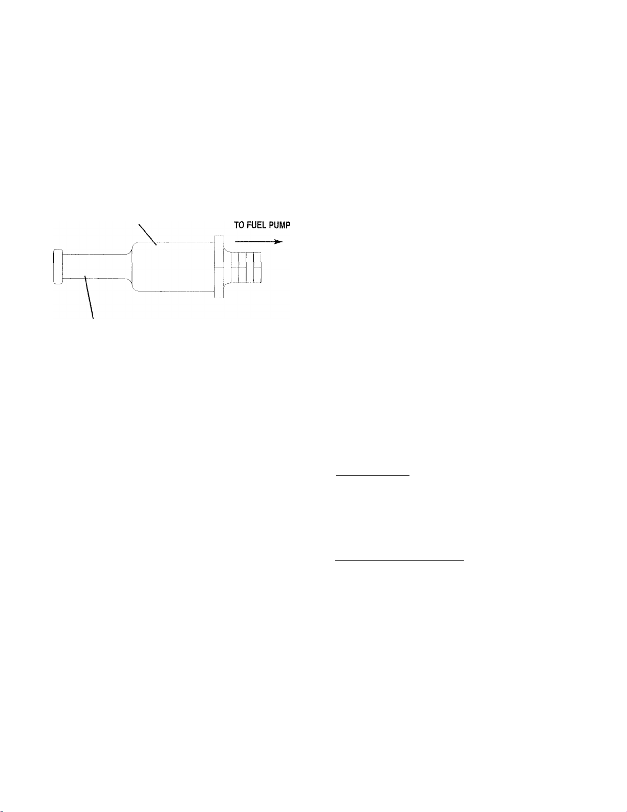
3.6 FUEL FILTER (GASOLINE ONLY)
Remove and replace the fuel filter (Figure 3.6)
once each year or every 100 hours of operation,
whichever comes first.
Figure 3.6 - Fuel Filter
FUEL FILTER
CUSTOMER FUEL CONNECTION
3.7 SPARK ARRESTOR MUFFLER
If the generator is not equipped with a spark arrestor
exhaust muffler and is to be used on any forest cov
ered, brush covered or grass covered unimproved
land, you may have to install a spark arrestor. The
spark arrestor must be maintained in effective work
ing order by the vehicle owner/operator.
For assistance in ordering, installing and maintaining
spark arrestor exhaust mufflers, contact your nearest
Generac Authorized Service Dealer.
Exhaust mufflers supplied by Generac are spark
arrestor types. Generac exhaust mufflers for recre
ational vehicle generators do not have a spark
arrestor screen, but are of the more efficient “toroid”
or “swirl” type. To remove carbon and combustion
deposits from such mufflers, remove the plug from
the muffler and run the engine for approximately 15
minutes. Shut down the engine, let the muffler cool
and install the plug.
---------ià WARNING Æ
Be sure to reinstall the muffler plug tightly.
Engine vibration could cause a loose plug to
fall out. Without the plug in place, hot engine
exhaust is directed out the opening. This hot
exhaust, depending on the installation, could
be directed to areas not able to withstand the
extreme heat such as wooden floor boards or
other flammable material. This could result in a
fire.
--------------
3.8 CLEANING THE GENERATOR
Keep fhe generator set as clean and dry as possible.
Protect the unit against excessive dust, dirt, corrosive
vapors, road splash, etc. Permitting dirt and mois
ture to accumulate on generator windings will have
an adverse effect on the insulation resistance of those
windings.
When moisture is allowed to remain in contact with
windings, some of the moisture will be retained in
voids and cracks in the insulation. This causes a
reduced insulation resistance and will eventually
cause problems. Dirt will make the problem worse,
since dirt tends to hold moisture in contact with
windings. Salt (as from sea air) also will worsen the
problem since it tends to absorb moisture from the
air. Salt and moisture, when combined, form a good
electrical conductor.
-A CAUTION A~
Do not use a forceful spray of water to clean
the generator. Water will enter the generator
A
interior and cause problems, and may also cont
aminate the generator fuel system.
3.9 BATTERY MAINTENANCE
All lead-acid batteries will discharge when not in use.
The generator battery should be inspected as follows;
♦ 5.9.1 WEEKLY
• Inspect the battery posts and cables for tightness
and corrosion. Tighten and clean as necessary.
• Check the battery fluid level of unsealed batteries
and, if necessary, fill with Distilled Water Only. Do
not use tap water in batteries.
♦ 3.9.2 EVERY SIX MONTHS
• Have the state of charge and condition checked.
This should be done with an automotive-type bat
tery hydrometer.
Servicing of the battery is to be performed or
supervised by personnel knowledgeable of batter
ies and the required precautions. Keep unautho
rized personnel away from batteries.
Damage will result if the battery connections are
made in reverse.
_____________
_______________________
NOTE:
____________________
Generac® Power Systems, Inc. 1 3
Page 16

MAINTENANCE
Section 3 - Maintenance
Cenerac Q-70G Recreational Vehicle Generator
DANGER
Do not dispose of the battery in a fire. The
A
battery is capable of exploding. Storage batter
ies give off explosive hydrogen gas. This gas
can form an explosive mixture around the bat
tery for several hours after charging. The
slightest spark can ignite the gas and cause an
explosion. Such an explosion can shatter the
battery and cause blindness or other injury.
Any area that houses a storage battery must be
properly ventilated. Do not allow smoking,
open flame, sparks, or any spark producing
tools or equipment near the battery. Discharge
static electricity from your body before touch
ing the battery by first touching a grounded
metal surface.
A battery presents a risk of electrical shock
A
and high short circuit current. The following
precautions are to be observed when working
on batteries:
• Remove watches, rings or other metal objects;
• Use tools with insulated handles;
• Wear rubber gloves and boots;
• Do not lay tools or metal parts on top of the
battery;
• Disconnect any charging source prior to connecting
or disconnecting battery terminals; and
• Do not use any jumper cables or booster battery to
crank and start the generator engine. If any battery
has discharged, remove it for recharging.
--------Mk WARNING ik
Do not open or mutilate the battery. Released
A
electrolyte has been known to be harmful to
the skin and eyes, and to be toxic.
The electrolyte is a dilute sulfuric acid that is
A
harmful to the skin and eyes. It is electrically
conductive and corrosive. The following
procedures are to be observed:
• Wear full eye protection and protective clothing;
• Where electrolyte contacts the skin, wash it off
immediately with water;
• Where electrolyte contacts the eyes, flush
thoroughly and immediately with water and seek
medical attention; and
• Spilled electrolyte is to be washed down with an
acid neutralizing agent. A common practice is to
use a solution of 1 pound (500 grams) bicarbonate
of soda to 1 gallon (4 liters) or water. The bicar
bonate of soda solution is to be added until the
evidence of reaction (foaming) has ceased. The
resulting liquid is to be flushed with water and the
area dried.
-------------
3.10 MAJOR SERVICE MANUAL
To obtain a service manual for your generator, con
tact Generac or your nearest Generac Authorized
Service Dealer. Make sure to identify your MODEL
NUMBER and SERIES.
3.11 DRIVE BELT
The engine drives the generator rotor by means of a
pulley and drive belt arrangement. The drive belt and
pulleys are warranted for the life of the generator. Drive
belt tension was properly adjusted before the unit was
shipped from die factory. If you suspect that drive belt
tension is incorrect, contact a Generac Authorized
Service Dealer.
3.12 EXERCISING THE GENERATOR
Generac recommends that you start and operate the
generator at least once every seven days. Let
the unit run for at least 30 minutes to “exercise”
the engine.
3.13 OUT OF SERVICE PROCEDURE
♦ 3.0.1 REMOVAL FROM SERVICE
If you cannot exercise the generator every seven days,
and it is to be out of service longer than 30 days, pre
pare the generator for storage as follows:
1. Start the engine and let it warm up.
2. Close the fuel shutoff valve in the fuel supply line
and allow the unit to shut down.
3. While the engine is still warm from running,
drain the oil completely. Refill the crankcase with
SAE lOW-30 oil having API classification “For
Service SF.”
4. Attach a tag to the engine indicating the viscosity
and classification of the oil in the crankcase.
5. Remove the spark plug and pour two or three
tablespoons of clean, fresh engine oil into the
spark plug threaded openings. Reinstall and
tighten the spark plug.
6. Remove the battery and store it in a cool, dry
room on a wooden board. Never store the battery
on any concrete or earthen floor.
7. Clean and wipe the entire generator.
_________________
1 *4 Generac* Power Systems, Inc.
Page 17

Section 3 - Maintenance
Cenerac Q-70C Recreational Vehicle Generator
MAINTENANCE
4 3.13.2 RETURN TO SERVICE
To return the unit to service after storage, proceed
as follows:
1.
Check the tag on the engine for oil viscosity and
classification. Verify that the correct recommend
ed oil is used in the engine (see Section 1.5.4,
Page 6). If necessary, drain and refill with the
proper oil.
2.
Check the state of the battery. Fill all cells of
unsealed batteries to the proper level with distilled
water. DO NOT USE TAP WATER IN THE BAT
TERY. Recharge the battery to 100 percent state of
charge, or, if defecUve, replace the battery.
Clean and wipe the entire generator.
3.
Reconnect the battery. Observe battery polarity.
4.
Damage may occur if the battery is connected
incorrectly.
Turn OFF all electrical loads. Add fuel if neces
5.
sary and then start the engine.
6.
Allow the unit to warm up thoroughly.
Apply electrical loads to at least 50 percent of the
7,
unit’s rated wattage capacity.
When the engine is thoroughly warmed up, shut
8.
it down.
9. Your generator is now ready for service.
3.14 WATTAGE REFERENCE GUIDE
Running
Watts
Battery Charger.................................................................500
Belt Sander (3”)
Chain Saw..................................................................... 1200
Circular Saw (6-12”)
Disc Sander (9”) .............................................................1200
Hand Drill (1”) ...............................................................1100
Hedge Trimmer.................................................................450
Impact Wrench .................................................................500
Lawn Mower ..................................................................1200
Electric Range (one element)..........................................1500
Television
Coffee Maker
Electric Skillet.................................................................1250
Hair Dryer
Light Bulb.........................................................................100
Microwave Oven ..............................................................700
Oil Burner on Furnace ......................................................300
Oil Fired Space Heater (140,000 Btu)
Radio......................................................................50 to 200
Slow Cooker .....................................................................200
*Furnace Fan (1/3 HP)....................................................1200
■"Refrigerator...................................................................600
*Air Conditioner (12,000 Btu)
■"Compressor (IHP).......................................................2000
■"Deep Freeze..................................................................500
"Milk Cooler
■"Submersible Pump (1-1/2 HP)
■"Submersible Pump (1 HP)
"Paint Sprayer, Airless (1/3 HP) ...............................600
"Table Saw (10”) ...........................................1750 to 2000
..............................................................
........................................
.......................................................
800 to 1000
1750 to 2000
..................................................................
.......................................................................
..............................
.......................................
...
..............................................................1100
.............................
..........................................
1000
1000
1200
400
1700
2800
2000
" Allow 2-1/2 times the listed watts for startiirg these
devices.
Generac® Power Systems, Inc. 1 5
Page 18

TROUBLESHOOTING
Section 4 - Troubleshooting
Generac Q-70G Recreational Vehicle Generator
4.1 TROUBLESHOOTING GUIDE
PROBLEM
The engine will not crank.
The engine cranks but
will not start.
The engine starts hard 1.
and runs rough.
The engine starts, but shuts
down when the Start/Stop 2.
switch is released.
CAUSE
1.
Fuse blown
2. Loose, corroded or defective 2.
battery cables
3. Defective engine Start/Stop
CORRECTION
1.
Replace fuse.
Tighten, clean or replace
as necessary.
3. Replace Start/Stop switch.
switch
4. Defective starter contactor 4. Replace contactor.
5. Defective starter motor 5. Replace starter motor.
6. Low or defective battery
1. Out of fuel 1.
2. Defective fuel pump 2.
Charge or replace battery.
6.
Replenish fuel.
Replace fuel pump.
3. Open #14 wire from 3, Check connections and.
engine control board insulation of #14 wires.
4. Flooded engine 4. Wait 5-10 minutes before trying.
5. Defective spark plug(s) 5.
Clean, re-gap or replace plug(s).
6. Fuel line shut-off closed 6. Open fuel line shut-off.
7.
Plugged fuel filter
7.
Clean or replace fuel filter.
Air cleaner 1. Check, clean or replace air cleaner.
plugged or damaged
2.
Defective spark plug(s) 2. Clean, re-gap or replace plug(s).
1. Engine oil level low 1. Check oil and add oil as needed.
Defective low oil
2.
Replace pressure switch.
pressure switch
3.
Defective high temperature
3. Replace temperature switch.
switch
4.
Defective engine control board
4. Replace control board.
5. Overheated engine 5. Check that the airflow
openings are adequate.
The Start/Stop switch is 1.
set to Stop, but the engine
continues to run.
Defective Start/Stop switch 1. Replace switch.
2.
Open/Disconnected #18 wire
between Start/Stop switch
and engine control board
3.
Open/Dlsconnected #0 wire
3. Reconnect or close wire.
between Start/Stop switch
and engine control board
4.
Defective engine control board 4. Replace control board.
There is no AC output from 1. Main line circuit breaker open 1.
the generator.
2.
Fault with vehicle circuit
2.
breaker and/or fuses
3. Transfer switch set to NORMAL 3.
4.
Start switch not held long 4. Stop, then restart the engine
enough to flash the field
5. Generator internal failure 5. Contact a Generac Authorized
1 6 Generac® Power Systems, Inc.
2.
Reconnect or close wire.
Reset circuit breaker
to ON (or closed).
Reset and replace if necessary.
Set switch to GENERATOR.
(Hold Start .switch for at least
2 seconds).
Service Dealer.
Page 19

Section 5 — Electrical Data
Generac Q-70G Recreational Vehicle Generator
Electrical Schematic and Wiring Diagram - Drawing No. A2776
T
ELECTRICAL
DATA
Page 20

PARTS
LISTS
Section 6 — Exploded Views and Parts Lists
Generac Q-70G Recreational Vehicle Generator
Base and Pulleys - Drawing No. A2753-F
1 S Generac® Power Systems, Inc.
Page 21

Section 6 — Exploded Views and Parts Lists
Generac Q-70G Recreational Vehicle Generator
Base and Pulleys - Drawing No. A2753-F
^PARTS
LISTS
ITEM
PART NO.
QTY.
DESCRIPTION ITEM PART NO. QTY.
1 86318 1 BASE, MOUNTING
90141
2
46911
3
4 25017
5 46526 2
6 22129 6
7 72391
8 77603 2 SAFETY BOLT 5/16"-18x 31/2"
9 22259 2
10
11
12 29459 2 SPRING, BELT TENSION 59
13
14 73146 4
15
16
17
18 40976 4 SHCS, M8-1,25x20mm
19
20 90859 1 COVER PLATE -EXTERNAL
21 75224D 1
22
23 75216 1 BELT (POLY V 4L)-40"
24 49451 1 WASHER, PULLEY RETAINER, 73
25 42633
26 77017
27 73118 1 CAPSCR., HEX HD.-3/8"-24 x 2-1/4"
28
29 91123
30 72375 1 HOUSING, BLOWER
31 73185
32 22097
33 77682 1 CAPSCR. HEX HD.-M5-0.80 x 80mm
34
35 49813 2 NUT, HEX M6x 1.0mm
36
37 90475
38 87769 1 FUEL FILTER 91
39 87768 1 FITTING-1/8"PIPETOy4" TUBE 93
40 87770 1 FUEL LINE 94
41 22413
42
43
52858
51730
75215
75209 2 SUPPORT, NYLON SLIDE
73174
79678
72383
73106D 1
74906
75242
45757
26925 1
7571OA
GROUND CABLE 45
1
MOUNT, (RUBBER) 46
4
CAPSCREW, HEX HD.3/8"-16 X 1/2" 47
8
LOCKWASHER-M10 48 A8475
LOCKWASHER, 5/16" -M8 49 A5802
SKID, RUBBER MOUNT 50
2
NUT, HEX-5/16"-18 56
NUT, FLANGED LOCK-M8-1.25
6
2 CAPSCR, HEX HD,-M8-1.25 x 60mm
WASHER, SPRING CNTR 60
2
SLIDE (NYLON) 61 74951 1
MANIFOLD, EXHAUST
1
RING, SEALING
2
GASKET, COLLECTOR PAN
2
PULLEY, ENGINE 69
PULLEY, ALT. 70
7GA. 0.41" X 1.62“ 74 77681
HHCS, 3/8"-24 X 1" (GRADE 5)
1
GUIDE, BLOWER HOUSING 76
1
7 TAPTITE, M6-1.00x20mm
BRACKET-FUEL PUMP 79
1
SPACER, BLOWER HOUSING 2-3/8" 81
1
LOCKWASHER, W'-MO
7
4
SPRING. GENERATOR SET MT
2 CAPSCREW, HEX HD,- M6-1.0 x 25mm
FUEL PUMP
1
CAPSCREW, HEX HD.-1/4"-20 x 1" 95 67210A 1
1
PIPE PLUG 3/8" SO. HD. 96 45756 9
1 FILL TUBE & PLUG 97
DESCRIPTION
44 74958 1 CAP & DIPSTICK ASSEMBLY
67871 1 0-RING, CAP
A5508 1 OIL FILL TUBE GASKET
75711 1 PIPE, OIL DRAIN ADAPTOR
1 SPECIAL LOCK WASHER, M5
1 TINNERMAN CLIP
22237
51
57
58
62
63 38750 3
64 74949 1 FiniNG, BARBED 90-DEGREE-5/16"
65
66 C4006 1
67
71
75
77 94670 1
78
80
82 79246 4
83
85
87 77643 1
90
22145
73179 1 OIL FILTER SUPPORT
70185 1 FILTER, OIL (FRAM#PH3614)
60108 1 10 PSI-SWITCH, OIL PRESSURE
74948 3 FITTING-5/16“
74950 1
73134 1
68548
29289 TAPE, FOAM-1/16" THICK X 8'
75281 1 SWITCH, HIGH TEMPERATURE
Cl 085 2 SCREW, PAN HEAD-M3-0.50 x 8mm
43182
75237
75474
90800 1
75226 1 COVER, AIR
56893 23
75229 1 SLIDE PAN, GASKET
75227 1 SLIDE PAN
22473
72384C
A1658 3
90088
81105 2
23897
22131 1
LOCKWASHER, 3/8"
8
FLATWASHER, 5/16" -M8
2
TUBE, OUTER OIL
TUBE, INNER OIL
ADAPTOR, OIL FILTER ADAPTER
CAPSCREW, HEX HD,- M6-1.00 x 30mm
GASKET, OIL FILTER ADAPTER
1
CABLE, BAHERY
LOCKWASHER-M3
2
WASHER, SPRING RETAINER
4
CAP, VINYL-LOS-2 WIRE
1
CAP, VINYL-17Dx42Lx2A
1
ELBOW, EXHAUST
CLAMP, EXHAUST
CRIMPTITE, N0.10-24x1/2"
CAPSCREW, HEX HEADM6-1,00 X 16mm WITH LOCK WASHER
FLATWASHER, 1/4” -M6
5
COVER, EXHAUST OUTLET
1
GASKET, EXHAUST OUTLET
LOCKWASHER, SPECIAL '/4"
1 CLAMP, VINYL COATED
FLANGE NUT, (SPECIAL) 5/16"-18
FLATWASHER, #10-M5
6
DECAL-GROUND
TAPTITE, M6-1.00X 10mm
FLATWASHER, M10
Generac* Power Systems, Inc. 1 3
Page 22

PARTS
LISTS
Section 6 — Exploded Views and Parts Lists
Cenerac Q-70G Recreational Vehicle Generator
Alternator and Control Panel - Drawing No. A2754-H
30 Generac® Power Systems, Inc.
Page 23

Section 6 — Exploded Views and Parts Lists
Generac Q-70G Recreational Vehicle Generator
Alternator and Control Panel - Drawing No. A2754-H
^RARTS
LISTS
ITEM PART NO.
1 75995
2 73163H 1
21441H 1
3
4 73159 1 BALL BEARING 37 49813
31971 1 BALL BEARING
5
6 72379-B 1
7 77006 4 STUD-STATOR 40 A8475
8 52858 4 M8-1.25 FLANGE LOCKNUT 41 54502
9 66386 1 BRUSH HOLDER 42 94192
10 66849 2 MS-0,8 X 16 LG. TAPTITE 43 83049
11
12
13
14 22473 4 1/4"/ M6-FLAT WASHER 47
15
16 74095 1 M6-1.0X60 LG. CAPSCREW 49 86315
17
18 A1658 2 SPECIAL LOCK WASHER, 'A"
19 74906 4 M6-1.0X20 LG. TAPTITE 51 22985
20
21 10^-74260 1 STARTER CABLE
22 22129
23
24 86316 1 PANEL SHEET METAL
25
26 C4258 1
27 75244
28 66476 2
29
30 75476 4
31
32 65795 1 BAHERY CHARGER RECTIFIER
33 90987
27756 4
86314
75234 1
22097
90141 2 GROUND CABLE
92234
22259 2
53650
86729
22264
QTY. DESCRIPTION
LOWER BEARING CARRIER 34 86317A
1
ROTOR ASSEM,
STATOR ASSEM, 36
UPPER BEARING CARRIER
NYLON WASHER
1 GENERATOR TOP HOUSING 45 51716
RESISTOR 46
5 'A"! M6-L0CK WASHER 48 25105
1 CONTROLLER P.C.B. 52
5/167 M8 LOCKWASHER 54
6
5/16--18HEX NUT 55 92113
1 4-PIN CONNECTOR 57 A8475-A
CONDUIT ASSEMBLY 58 51715
1 ASSEMBLY, REMOTE CABLE 59 90157
M6-1.0X12LG CAPSCREW- 60 55440
W/LOCKWASHER
1 STARTER CONTACTOR 62 31791
M4-0.7X16LG. CAPSCREW 63 23897
4
#8/ M4-LOCK WASHER 64 74908
2 M3-0,5x12LG,PPHMS 66 75763
ITEM PART NO. QTY. DESCRIPTION
35 75235
82737
38
39 43182
44 22152 6 M5-LOCK WASHER
50
53 22676
56
61
65 23484-S
49815
82081 1 CIRCUIT BREAKER 30A. 2P
45771
90734 4 M4-0.7 X 12 LG. CAPSCR.W/LOCK-
32300
87798
75210-A 1 TERMINAL BLOCK
94191 1 DECAL, CUSTOMER CONNECTION
1
PANEL SUPPORT BRACKET
2
M5-0.8 X 30 LG, CAPSCREW
4 VIBRATION MOUNT
4 M6-1.0HEX NUT
1
M5-08 X 16 LG. HEX HD. CAPSCR.
2 M3-LOCK WASHER
3 MS-SPECIAL LOCK WASHER
1 C/BREAKER 3.0A
1 HARNESS, CUSTOMER CONNECTION
1 REGULATOR VOLTAGE
4
M5-0.8 HEX NUT
4 M8-1.25 HEX NUT
4 #6-32 X '/4" SCREW W/LOCK WASHER
1
PANEL COVER
WASHERS FLAT WASHER
1
#6-FLAT WASHER
1 FUSE HOLDER
1 FUSE AGC-15A.
1 SWITCH S.RD.T. 6A.-(START-STOP)
1 SWITCH S.P.D.T.-(FUEL PUMP)
1
#8 SPECIAL LOCKWASHER
1 M4-0.7 HEX NUT
1
DECAL, CB RATING 30A.
2 M5-0.8 X 25, CAPSCREW
1
CLAMP, HOSE
3 #10/M5-FLAT WASHER
1 M5-0.8X 10 LONG TAPTITE
1 BUSHING
1 BOOT, BATTERY CABLE
Generac* Power Systems, Inc.
Page 24

PARTS
LISTS
Section 6 — Exploded Views and Parts Lists
Generac Q-70C Recreational Vehicle Generator
Engine - Drawing No. 79216-E
H
3
g
oO
0>
/1'©'
i'('
o
03
ill {ili
(O
;1
§
O
X
\
0.
<
X
o
K
s
'i-
'f
V
ro
n
7
// 'i.\
© \
©-
!“)
iQ
03
Oo
I (
/k \
x./A \
Vi
>;
'\
A
s i )
i jA
//
77 |l 1 A/
%ui
r
I -7.7
I;
_ I
A
GO
Igr^j
CN 1
+ 1
Os
ji.
vuVy i'.Ar‘
1^ IfX“
IC’Vj 7^ '.'1^:
% / ^
7/7r
__
w
■■■■■I]
©1
;a
■ ■ r
)7/
01}
Q7 7 S
>7i ' i
¥
llj -1 ™rf
S 05 K>
111 f'
1
" 1.1;=^’'
1*^
i VI
,
m
ss Generac® Power Syst^ems, Inc.
Page 25

Section 6 — Exploded Views and Parts Lists
Cenerac Q-70G Recreational Vehicle Generator
Engine - Drawing No. 79216-E
^PARTS
LISTS
ITEM
10 89967 1 BREATHER SCREW 59 72361 1 GOVERNOR SHAFT BUSHING
11 70596
12 69336 1 OIL SUMP GASKET
13
14 67888 2 3/8” NPT OIL DRAIN PLUG 64 72365 1 GOVERNOR SHAFT WASHER
15
16 75247 1 OIL SUMP ASSEMBLY 66 67806 4 CYLINDER HEAD DOWEL
17
18
19 75248 2 STANDARD PISTON ASSEMBLY 75
20 75249 2 STANDARD PISTON RING SET 76 67910 2 INTAKE VALVE SEAT
21
22
23 75251 2 CONNECTING ROD ASSEMBLY 82 73123 1 AIR FILTER (NOT SHOWN)
24
25
26 69317 2
27 67816 4
28
29
30
31
32
33
34
35 70594 2
36
37
38 68554A 1 GOVERNOR SHAFT SEAL
39
40
41
42
PART NO. QTY. DESCRIPTION ITEM PART NO. QTY. DESCRIPTION
1 69331
2 69333 1 SLEEVE BEARING 44 67885 4 M6 NYLON NUT
3 67805 1
4
79234 1 NO. 1 CYLINDER HEAD ASSEMBLY 46 70535
5
79235
6 70169 4
7
69332
8 104 85110
9 72315
69325 8
72334 1 CRANKSHAFT ASSEMBLY 65
67924
67878
69327 4 PISTON LOCKING RING
75250
72346 4 CONNECTING ROD BOLT 83
69316
69320
70513
70584
70530
72358
69379
67895
67158
68574 1 1/8” NPT PLUG PIPE 98 75271
68573 1 OIL PUMP O-RING 100 91481 1
70506
70554
70568 4 ROCKER ARM STUD
1 CYLINDER ASSEMBLY 43
OIL SEAL
1 NO. 2 CYLINDER HEAD ASSEMBLY
SEALING WASHER 51
2 CYLINDER HEAD GASKET
1 BREATHER ASSEMBLY
1
BREATHER GASKET 57
1 BREATHER TUBE 60
CYLINDER HEAD BOLT
1 OIL SEAL ASSEMBLY
OIL SUMP BOLT
9
2
STANDARD PISTON RING 81
2 EXHAUST VALVE 84 C3633
INTAKE VALVE 85
VALVE SPRING 86
4
VALVE SPRING RETAINER 88
4 VALVE KEEPER 89 72305
4
VALVE TAPPET 90
1
CAMSHAFT ASSEMBLY 91
1 INTAKE MANIFOLD
2
CARBURETOR MOUNTING GASKET 93
2 INTAKE MANIFOLD GASKET 94 70577 4 PUSH ROD
CARBURETOR MOUNTING BOLT 95
4 INTAKE MANIFOLD MOUNTING BOLT 97 70566 4 ROCKER ARM SUPPORT
1 OIL GALLEY O-RING
1
CARBURETOR SPACER 102
45
47
52
53
61
62
73
74
78
92
99
101
75253 4 WASHER VALVE COVER SEAL
75254 4 VALVE ADJUST SCREW
1
OIL SCREEN
C2881 1 STARTER MOTOR (NOT SHOWN)
72536 4 IGNITION ARMATURE SCREW
72347 2
75258 1 ENGINE GASKET KIT
66480 1
72362 1 GOVERNOR SHAFT BUSHING
70199 1 BREATHER BAFFLE
72366 1
68555 2
68572 2 OIL PUMP SCREW
75272 2
70122
67813 4 VALVE GUIDE
70592 1
70593 1
67156 2
69341 1 FOAM PRE-CLEANER
70597 1 AIR INLET TUBE
67920 2 VALVE COVER GASKET
69328 2 VALVE COVER
70547 1 OIL PUMP ASSEMBLY
70536 1 GOVERNOR SLIDER
70599 4
67897 2 EXHAUST GASKET (NOT SHOWN)
91480 1 ROCKER ARM AND COVER
Dll 98 1 GOVERNOR CRANK
SPARK PLUG
AIR CLEANER GASKET
COTTER PIN
CRANKCASE DOWEL
SPARK PLUG TERMINAL
4 VALVE STEM SEAL
AIR CLEANER BASE
AIR CLEANER COVER
1
AIR CLEANER COVER SCREW
AIR CLEANER BASE SCREW
1
BREATHER DEFLECTOR
ROCKER ARM
1 VALVE OVERHAUL KIT
GASKET AND CAP ASSEMBLY
Generac* Power Systems, Inc. 53
Page 26

PARTS
LISTS
Section 6 — Exploded Views and Parts Lists
Cenerac Q-70G Recreational Vehicle Generator
Engine Sheet Metal - Drawing No. 89403-K
2«4 Generac* Power Systems, Inc.
Page 27

Section 6 — Exploded Views and Parts Lists
Generac Q-70G Recreational Vehicle Generator
Engine Sheet Metal - Drawing No. 89403-K
jpms
LISTS
ITEM
1 1
2
3
4
5 87865
6 A4456
7
8 56893
10 87750
11 74916
12 74908
13
14
15 78859
16
17
19
20
21
22 75246
23
24
25 73186
26 81108
27 22717B 1 GROMMET -RUBBER
28
29
30
31
33
34
35
36
PART NO.
99258
67198N
67890
86313
73190
78858
74902
66476
73191
42907
22129
10^-74260
74900
22717A 3
67866A
77001A
73132
87858A
29289
87858B
50277
QTY.
2FT. FOAM TAPE
1
1 BEVELED WASHER
1
1
1
1
23
1 SCROLL, FLYWHEEL
1 COVER, BASE CYL. #2
9
1
1 COVER, VALLEY
1
2
4
1 COVER, BASE CYL. #1
2
2 LOCK WASHER-M8
4
1
1
1 WRAPPER, CRANKCASE
1
1 0-RING
1 PLUG, OIL FILL
2 BOOT, SPARK PLUG
1
1
1 OIL DRAIN DECAL
DESCRIPTION
SEE ENGINE EXPLODED VIEW of ENGINE
KEY-WOODRUFF 6 x 22MM
HEX NUT
PLUG, FLYWHEEL ACCESS
3/8" SPECIAL LOCK WASHER
HOUSING, ENGINE TOP
SCREW (CRIMPTITE) NO. 10-24 x 1/2"
SCREW (TAPTITE) M5 x 10MM
WRAPPER CYL. #2
WRAPPER, CYL. #1
WRAPPER, BARREL
HHCS/LW-M6 x 1.0 X 12MM
CAPSCREW, HEX HD.-M8 x 1.25 x 16MM
SCREW (TAPTITE) 3/8"-16 x 1-1/4"
WIRE ASSEMBLY-NO, 16
STARTER COVER
BUSHING, SNAP
GROMMET -RUBBER
GROUND WIRE ASEMBLY-CYL. #1
GROUND WIRE ASSEMBLY-CYL. #2
Generac* Power Systems, Inc. 2S
Page 28

PARTS
LISTS
Section 6 — Exploded Views and Parts Lists
Cenerac Q-70G Recreational Vehicle Generator
Carburetor - Drawing No. 93753-F
26 Generac* Power Systems, Inc.
Page 29

Section 6 — Exploded Views and Parts Lists
Cenerac Q-70G Recreational Vehicle Generator
Carburetor - Drawing No. 93753-F
^PARTS
LISTS
ITEM PART NO.
1 73112B 1 CARBURETOR ASSEMBLY
2 74962c
74962g 1 SPRING, GOVERNOR q-70g
3 70155
4
5
6 74961
7
8
9 73131
10 66476
11 70575
12
13
14 74947 1
15 89473
16
17
18 31879
19 22159
20
21
22
23 74946
25
26
27
28
29
30 66829
31
32
33
70108
56893
47227
37398
70125
73374
91306 1
77091 1
89870
72536
87770
30340 1
C2338B
C2338
91352C 1
75252
A7782A 1
40173
75944 1 BRACKET, GOVERNOR SPRING
70594
77075
QTY. DESCRIPTION
1
1 LEVER, GOVERNOR
1 ROD, GOVERNOR TO CARBURETOR
5
1 BRACKET, GOVERNOR ADJUSTER
1
1
1
2
2 SCREW, HEX - M6-1.0 X 25MM
1
1
1
4
4
1
4
1
1 LINK, CHOKE
1 DECAL, AIR CLEANER PRIMEPACT 66G
1
1
2
2
2
1
SPRING, GOVERNOR
SCREW (CRIMPTITE) - #10-24 X 1/2”
SCREW, GOVERNOR ADJUSTER
NUT, HEX LOCK (NYLON)
BRACKET, AIR CLEANER SUPPORT
SCREW, HEX - M6-1.0 X 12MM
SPRING, ANTI-LASH
BRACKET, CHOKE SUPPORT
ROD, CHOKE CONTROL
BI-METAL ASSEMBLY, CHOKE
SOLENOID, CHOKE
HAIR PIN, COTTER
FLAT WASHER - #4
LOCK WASHER - #4
SOLENOID FUEL SHUT-OFF (Q70G ONLY)
SCREW, PAN HD, MACH. - #4-40 X 1/4”
LINE, FUEL - 5/16” I.D.
HOSE - FUEL, 4.5” LG.
DECAL, AIR CLEANER - PRIMEPACT 55G
DECAL, AIR CLEANER - Q-70G
KIT, CARBURETOR OVERHAUL - NOT SHOWN
FLYWHEEL ASSEMBLY
CLAMP, HOSE (SCREW TYPE)
RIVET - 1/8” DIAMETER X 1/8” LONG
CAPSCREW, HEX HD. - M6-1.0 X 93 LG. W/WASHER
COVER, CHOKE COIL
Generac* Power Systems, Inc. 27
Page 30

Section 7 - Warranty
Cenerac Q-70G Recreational Vehicle Generator
CALIFORNIA AND FEDERAL EMISSION CONTROL WARRANTY STATEMENT
YOUR WARRANTY RIGHTS AND OBLIGATIONS
The California Air Resources Board (GARB) and the United States Environmental Protection Agency (EPA), together with
Generac Power Systems, Inc. (Generac), are pleased to explain the Emission Control System Warranty on your new engine.*
New utility, and lawn and garden equipment engines must be designed, built smd equipped to meet stringent anti-smog stan
dards for the state of California and the federal government. Generac will warrant the emission control system on your
engine for the periods of time listed below provided there has been no abuse, neglect, unapproved modification or improp
er maintenance of your engine.
Your emission control system may Include parts such as the carburetor, ignition and exhaust systems. Generac will repair
your engine at no cost to you for diagnosis, replacement parts and labor, should a warrantable condition occur.
MANUFACTURER'S EMISSION CONTROL SYSTEM WARRANTY COVERAGE:
Emissions control systems on 1997 and later model year engines are warranted for two years as hereinafter noted. If, dur
ing such warranty period, any emission-related component or system on your engine is found to be defective in materials or
workmanship, repairs or replacement will be performed by a Generac Authorized Warranty Service Facility.
PURCHASER'S/OWNER'S WARRANTY RESPONSIBILITIES:
As the engine purchaser/owner, you are responsible for the completion of all required maintenance as listed in your factory
supplied Owner’s Manual. For warranty purposes, Generac recommends that you retain all receipts covering maintenance
on your engine. However, Generac cannot deny warranty solely because of the lack of receipts or for your failure to ensure
the completion of all scheduled maintenance.
As the engine purchaser/owner, you should, however, be aware that Generac may deny any and/or all warranty coverage or
responsibility if your engine, or a part/component thereof, has failed due to abuse, neglect, improper maintenance or unap
proved modifications, or the use of counterfeit and/or ‘grey market’ parts not made, supplied or approved by Generac.
You are responsible for presenting your engine to a Generac Authorized Warranty Service Facility as soon as a prob
lem occurs. The warranty repairs should be completed in a reasonable amount of time, not to exceed 30 days.
Warranty service can be arranged by contacting either your selling dealer or a Generac Authorized Warranty Service Facility.
To locate the Generac Authorized Warranty Service Facility nearest you, call our toll-free number:
1-800-333-1322
IMPORTANT NOTE: This warranty statement explains your rights and obligations under the Emission Control System
Warranty (ECS Warranty), which is provided to you by Generac pursuant to California and federal law. See also the "Generac
Limited Warranties for Generac Power Systems, Inc.,’’ which is enclosed herewith on a separate sheet, also provided to you
by Generac. The ECS Warranty applies only to the emission control system of your new engine. If there is any conflict in
terms between the ECS Warranty and the Generac Warranty, the ECS Warranty shall apply except in circumstances where
the Generac Warranty may provide a longer warranty period. Both the ECS Warranty and the Generac Warranty describe
important rights and obligations with respect to your new engine.
Warranty service can be performed only by a Generac Authorized Warranty Service Facility. When requesting warranty ser
vice, evidence must be presented showing the date of the sale to the original purchaser/owner. The pimchaser/owner shall
be responsible for any expenses or other charges Incurred for service calls and/or transportation of the product to/from the
inspection or repair facilities. The purchaser/owner also shall be responsible for any and/or all damages or losses incurred
while the engine is being transported/shlpped for inspection or warranty repairs.
If you have any questions regarding your warranty rights and responsibilities, you should contact Generac at the fol
lowing address:
ATTENTION WARRANTY DEPARTMENT
GENERAC POWER SYSTEMS, INC.
P.O. BOX 297
WHITEWATER, Wl 53190
Part 1
S8 Generac* Power Systems, Inc.
Page 31

Section 7 - Warranty
Cenerac Q-70G Recreational Vehicle Generator
EMISSION CONTROL SYSTEM WARRANTY
Emission Control System Warranty (ECS Warranty) for 1997 and later model year engines:
(a) Applicability: This warranty shall apply to 1997 and later model year engines. The ECS Warranty Period shall begin on
the date the new engine or equipment is purchased by/dellvered to its original, end-use purchaser/owner and shall contin
ue for 24 consecutive months thereafter.
(b) General Emissions Warranty Coverage: Generac warrants to the original, end-use purchaser/owner of the new engine or
equipment, and to each subsequent purchaser/owner, that each of its engines is ...
(1) Designed, built and equipped so as to conform with all applicable regulations adopted by the EPA and CARB pursuant
to their respective authority, and
(2) Free from defects in materials and workmanship which, at any time during the ECS Warranty Period, may cause a war
ranted emlsslons-related part to fall to be identical in all material respects to the part as described in the engine manu
facturer’s application for certification.
(c) The ECS Warranty only pertains to emlsslons-related parts on your engine, as follows:
(1) Any warranted, emlssions-related parts that are not scheduled for replacement as required maintenance in the Owner’s
Manual shall be warranted for the ECS Warranty Period. If any such part falls during the ECS Warranty Period, it shall
be repaired or replaced by Generac according to Subsection (4) below. Any such part repaired or replaced under the ECS
Warranty shall be warranted for the remainder of the ECS Warranty Period.
(2) Any warranted, emlsslons-related part that is scheduled only for regular inspection as specified in the Owner’s Manual
shall be warranted for the ECS Warranty Period. A statement in such written instructions to the effect of “repair or replace
as necessary” shall not reduce the ECS Warranty Period. Any such part repaired or replaced under the ECS Warranty
shall be warranted for the remainder of the ECS Warranty Period.
(3) Any warranted, emlsslons-related part that is scheduled for replacement as required maintenance in the Owner’s
Manual shall be warranted for the period of time prior to the first scheduled replacement point for that part. If the part
falls prior to the first scheduled replacement, the part shall be repaired or replaced by Generac according to Subsection
(4) below. y\ny such emlssions-related part repaired or replaced under the ECS Warranty shall be warranted for the
remainder of the ECS Warranty Period prior to the first scheduled replacement point for such emlssions-related part.
(4) Repair or replacement of any warranted, emlssions-related part under this ECS Warranty shall be performed at no
charge to the owner at a Generac Authorized Warranty Service Facility.
(5) When the engine is Inspected by a Generac Authorized Warranty Service Facility, the owner shall not be held responsi
ble for diagnostic costs if the repair is deemed warrantable.
(6) Generac shall be liable for damages to other original engine components or approved modifications proximately caused
by a failure under warranty of any emission-related part covered by the ECS Warranty.
(7) Throughout the ECS Warranty Period, Generac shall maintain a supply of warranted emission-related parts sufficient
to meet the expected demand for such emission-related parts,
(8) Any Generac authorized and approved emission-related replacement part may be used in the performance of any ECS
Warranty maintenance or repairs and will be provided without charge to the purchaser/owner. Such use shall not reduce
Generac’s ECS Warranty obligations.
(9) Unapproved, add-on, modified, counterfeit and/or ‘grey market’ parts may not be used to modify or repair a Generac
engine. Such use voids this ECS Warranty and shall Ire sufficient grounds for disallowing an ECS Warranty claim.
Generac shall not be held liable hereunder for failures of any warranted parts of a Generac engine caused by the use of
such an unapproved, add-on, modified, counterfeit and/or ‘grey market’ part.
EMISSION RELATED PARTS INCLUDE THE FOLLOWING:
1) Fuel Metering System:
1.1) Gasoline carburetor assembly and its
internal components (if so equipped).
a) Fuel filter (if so equipped)
b) Carburetor gaskets
c) Fuel pump (if so equipped)
1.2) LPG carburetion assembly and its
Internal components (if so equipped),
a) Fuel controller (if so equipped)
b) Mixer and its gaskets (if so equipped)
c) Carburetor and its gaskets (if so equipped)
d) Primary gas regulator (if so equipped)
2) Air Induction System including:
a) Intake pipe/manifold
b) Air cleaner
3) Ignition System Including:
a) Spark plug
b) Ignition module
4) Catalytic Muffler Assembly (if so equipped) including:
a) Muffler gasket
b) Exhaust manifold
5) Crankcase Breather Assembly including:
a) Breather connection tube
e) LP liquid vaporizer (if so equipped)
‘Generac engine types covered by this warranty statement include the following:
1) Utility
2) Lawn and Garden Equipment
3) Recreational Vehicle (RV) Generator
4) Industrial Mobile (IM) Generator
Part 2
Generac* Power Systems, Inc. SS
Page 32

Section 7 - Warranty
Generac Q-70G Recreational Vehicle Generator
GENERAC POWER SYSTEMS' THREE-YEAR LIMITED WARRANTY
FOR RECREATIONAL VEHICLE GENERATORS
NOTE; ALL UNITS MUST BE INSTALLED BY GENERAC POWER SYSTEMS AUTHORIZED SERVICE FACILITIES.
For a period of 3 (tliree) years or 2,000 (two thousand) hours of operation from the date of original sale, whichever occurs first, Generac
Power Systems, Inc. (Generac) will, at its option, repair or replace any part which, upon examination, inspection and testing by Generac or
a Generac Authorized Warranty Service Facility, is found to be defective under normal use and service, in accordance with the warranty
schedule set forth below. Any equipment that the purchaser/owner claims to be defective must be returned to and examined by the nearest
Generac Authorized Warranty Service Facility. All transportation costs under the warranty, including return to the factory, are to be borne
and prepaid by the purchaser/owner. This warranty applies only to Generac generators sold and rated for "Recreational Vehicle” (RV) appli
cations, as Generac has defined Recreational Vehicle generator applications. This warranty is effective only upon Generac’s receipt, from
the original purchaser/owner, of a completed Warranty Registration Card. This card is the only valid registration identification and must be
presented at time of request for warranty service. Claims will not be accepted without presentation of the Warranty Registration Card. The
factory recommends exercising the unit one half-hour every season.
WARRANTY SCHEDULE - COMMERCIAL APPLICATIONS
YEAR ONE - 100% (one hundred percent) coverage on part(s), labor, removal and reinstallation listed:
• Engine - All components
• Alternator - All components
• Transfer System - All components
WARRANTY SCHEDULE - CONSUMER/PERSONAL APPLICATIONS
YEARS ONE AND TWO - 100% (one hundred percent) coverage on part(s), labor, removal and reinstallation listed:
• Engine - All components
• Alternator - All components
• Transfer System - All components
YEAR Three - 100% (one hundred percent) only on selected part(s) and labor listed (/Vny labor and part(s) not listed, and removal and rein
• Rotor, Stator, Computer Control Board, (if applicable with regard to Üie generator) Cylinder Block, Cylinder Head, Crankshaft, Piston(s), Valve,
Valve Lifter(s), Intake and Exliaust IManlfolds
stallation are the owner’s responsibility):
FOR THE LIFE OF THE RECREATIONAL VEHICLE GENERATOR (IF SO EQUIPPED)
The drive train belt and pulleys (if so equipped) on generators used in recreational vehicles shall be warranted against failure due to defec
tive materials or normal usage for the life of the generator. For the original purchaser/owner, this drive train warranty shall include part(s)
and labor (removal and réinstallation are not included) plus $50 (fifty dollars - U.S.) payment upon return of the failed belt or pulley by
the original purchaser/owner. For subsequent purchaser/owner, this drive train warranty shall cover belt and pulley part(s) ONLY (labor not
included). Labor, removal and réinstallation is Üie responsibility of the subsequent purchaser/owner.
Generac RV generators manufactured prior to December 31, 1997, DO NOT have a transferable warranty. Generac RV generators manu
factured after January 1, 1998, have a transferable warranty to the second owner ONLY for the remainder of the three-year limited war
ranty. Proof-of-purchase is required and must be presented to a Generac Authorized Warranty Service Facility prior to the performance of
any warranty service.
All warranty expense allowances are subject to the conditions defined in Generac's super se®Y|CE information manual.
THIS WARRANTY SHALL NOT APPLY TO THE FOLLOWING:
• Costs of normal maintenance, adjustments, installation and start-up.
• Failures caused by any contaminated fuels or oils.
• Failures due, but not limited, to normal wear and tear, accident, misuse, abuse, negligence or improper installation. As with all
mechanical devices, the GN-Series engines need periodic part(s) service and replacement to perform well. This warranty will not cover
repair when normal use has exhausted the life of a part(s) or engine.
• Failures caused by any external cause or act of God, such as collision, theft, vandalism, riot or wars, nuclear holocaust, fire, freezing,
lightning, earthquake, windstorm, hail, volcanic eruption, water or flood, tornado or hurricane.
• Products that are modified or altered in a manner not authorized by Generac in writing.
• Any incidental, consequential or indirect damages caused by defects in materials or workmanship, or any delay in repair or replace
ment of the defective part(s).
• Failure due to misapplication.
• Telephone, telegraph, teletype or other communication expenses.
• Living or travel expenses of person(s) performing service, except as specifically Included within the terms of a specific unit warranty period.
• Rental equipment used while warranty repairs are being performed.
• Overnight freight costs for replacement part(s).
• Overtime labor.
• Starting batteries, fuses, light bulbs and engine fluids.
THIS WARRANTY IS IN PLACE OF ALL OTHER WARRANTIES, EXPRESSED OR UMPLIED. SPECIFICALLY, GENERAC (MAKES NO OTHER
WARRANTIES AS TO THE IMERCHANTABILITY OR FITNESS FOR A PARTICULAR PURPOSE. Some states do not allow limitations on how
long an implied warranty lasts, so the above limitation may not apply to you.
GENERAC’S ONLY LIABILITY SHALL BE THE REPAIR OR REPLACEMENT OF PART(S) AS STATED ABOVE. IN NO EVENT SHALL GEN
ERAC BE LIABLE FOR ANY INCIDENTAL OR CONSEQUENTIAL DAMAGES, EVEN IF SUCH DAMAGES ARE A DIRECT RESULT OF GEN
ERAC’S NEGLIGENCE, Some states do not allow the exclusion or limitation of incidental or consequential damages, so the above limita
tion may not apply to you. Purchaser/owner agrees to make no claims against Generac based on negligence.
This warranty gives you specific legal rights. You also may have other rights that vary from state to state.
GEMERAC® POWER SYSTEMS, INC.
P.O. BOX S • WAUKESHA, Wl 531 B7
Part No. CeS73
Revision O (10/1 B/OO]
Printed in U.S.A.
 Loading...