

Page 1
POWER SYSTEMS, INC.
®
Owner’s Manual
Liquid-cooled, Prepackaged
Standby Generators
Model Numbers
(Natural Gas)
004090-2 004091-2
004092-2 004093-2
004094-2 004095-2
004096-2 004097-2
004474-0 (w/TS)
(Liquid Propane Vapor)
004124-1 004125-1
004126-1 004127-1
004128-1 004130-1
004131-1
004475-0 (w/TS)
ONLY QUALIFIED ELECTRICIANS OR CONTRACTORS
SHOULD ATTEMPT INSTALLATION!!
Page 2
Generac®Power Systems, Inc.
INTRODUCTION
Thank you for purchasing this model of the standby generator set product line by Generac Power Systems.
Every effort was expended to make sure that the information and instructions in this manual were both accurate and current at the time the manual was written.
However, the manufacturer reserves the right to change,
alter or otherwise improve this product(s) at any time
without prior notice.
READ THIS MAN UAL THOROUGHLY
If you do not understand any portion of this manual,
contact Generac or your nearest Generac Authorized
Service Dealer for starting, operating and servicing procedures.
Throughout this publication, and on tags and
decals affixed to the generator, DANGER, WARNING,
CAUTION and NOTE blocks are used to alert you to special instruction about a particular service or operation
that may be hazardous if performed incorrectly or carelessly . Observe them carefully. Their definitions are as follows:
After this heading, you can read instructions that, if
not strictly complied with, will result in personal injury
or property damage.
After this heading, you can read instructions that, if not
strictly complied with, may result in personal injury or
property damage.
After this heading, you can read instructions that, if not
strictly complied with, could result in damage to equipment and/or property.
NOTE:
After this heading, you can read explanatory statements that require special emphasis.
These safety warnings cannot eliminate the hazards that
they indicate. Common sense and strict compliance with
the special instructions while performing the service are
essential to preventing accidents.
Four commonly used safety symbols accompany the
DANGER, WARNING and CAUTION blocks. The type of
information each indicates is as follows:
This symbol points out important safety information
that, if not followed, could endanger personal safety
and/or property of you and others.
This symbol points out potential explosion hazard.
This symbol points out potential fire hazard.
This symbol points out potential electrical shock
hazard.
The operator is responsible for proper and safe use of
the equipment. We strongly recommend that the operator read this Owner's Manual and thoroughly understand all instructions before using this equipment. We
also strongly recommend instructing other users to
properly start and operate the unit. This prepares them
if they need to operate the equipment in an emergency.
OPERATION AND MAINTENANCE
It is the operator's responsibility to perform all safety
checks, to make sure that all maintenance for safe operation is performed promptly, and to have the equipment
checked periodically by a Generac Authorized Service
Dealer. Normal maintenance service and replacement of
parts are the responsibility of the owner/operator and,
as such, are not considered defects in materials or workmanship within the terms of the warranty. Individual
operating habits and usage contribute to the need for
maintenance service.
Proper maintenance and care of your generator ensure a
minimum number of problems and keep operating
expenses at a minimum. See your Generac Authorized
Service Dealer for service aids and accessories.
Operating instructions presented in this manual
assume that the standby electric system has been
installed by a Generac Authorized Service Dealer or
other competent, qualified contractor. Installation of
this equipment is not a “do-it-yourself” project.
HOW TO OBTAIN SERVICE
When your generator requires servicing or repairs, simply contact a Generac Authorized Service Dealer for
assistance. Service technicians are factory-trained and
are capable of handling all of your service needs.
When contacting a Generac Authorized Service Dealer
or the factory about parts and service, always supply the
complete model number of your unit as given on the
front cover of this manual or on the DA TA CARD affixed
to the unit.
AUTHORIZED SERVICE
DEALER LOCATION
To locate the GENERAC AUTHORIZED SERVICE
DEALER nearest you, please call this number:
1-800-333-1322
OR
Locate us on the web at:
www.generac.com
Page 3
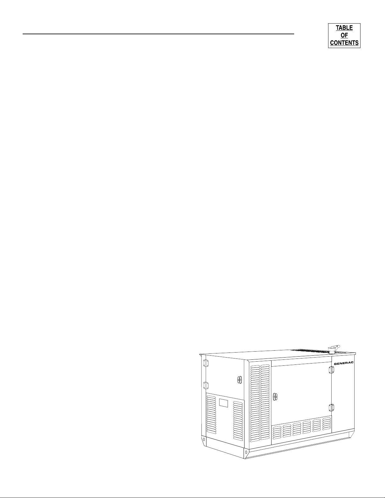
Table of Contents
Guardian Liquid-cooled 10 kW, 15 kW, 20 kW and 25 kW Generators
Generac®Power Systems, Inc. 1
INTRODUCTION
............................................................
SAFETY RULES ........................................................................2
Section 1
GENERAL INFORMATION ........................................................4
Generator ....................................................................................4
Automatic System Operation ......................................................4
Generator AC Connection Systems............................................4
Main Circuit Breaker....................................................................5
Generator Fuel System ..............................................................5
Engine Protective Devices ..........................................................5
Unpacking....................................................................................6
Generator Specifications ............................................................6
Lifting the Generator ..................................................................7
Engine Specifications..................................................................7
Fuel Consumption ......................................................................7
Lifting the Generator ..................................................................7
Engine Oil Recommendations ....................................................7
Before Installation........................................................................8
Section 2
STANDBY GENERATOR INSTALLATION ................................9
Basic Standby Electric System..............................................................9
Emergency Circuit Isolation Method....................................................10
Total Circuit Isolation Method..............................................................10
Grounding the Generator ....................................................................10
Generator AC Neutral Connections ....................................................10
Transfer Switch Start Signal Connections ..........................................10
Battery Installation ..............................................................................10
Preparation Before Start-Up................................................................11
Section 3
OPERATION ............................................................................12
Using a Standard “GTS”Transfer Switch ..................................12
Control Console Components ..................................................13
Manual Transfer and Startup ....................................................13
Retransfer and Shutdown..........................................................14
Automatic Operation..................................................................14
Weekly Exercise Cycle..............................................................14
Engine Heater ..........................................................................14
Section 3
MAINTENANCE........................................................................15
Maintenance Performed by
Authorized Service Facilities ....................................................15
Overload Protection for Engine DC Electrical System..............15
Checking Fluid Levels ..............................................................15
Maintenance Owner/Operator Can Perform ..............................16
Miscellaneous Maintenance......................................................17
TROUBLESHOOTING..............................................................18
Section 4
NOTES......................................................................................19
Section 5
WIRING DIAGRAMS AND SCHEMATICS..........................20-25
Section 6
EXPLODED VIEWS AND PARTS LISTS............................26-43
Section 7
INSTALLATION DRAWINGS ..............................................44-45
Section 8
WARRANTY.......................................................46 - Back Cover
Figure 1- Water Cooled Emergency Power System
Page 4
2 Generac®Power Systems, Inc.
Study these SAFETY RULES carefully before installing,
operating or servicing this equipment. Become familiar
with this Owner’s Manual and with the unit. The generator can operate safely, efficiently and reliably only if it is
properly installed, operated and maintained. Many accidents are caused by failing to follow simple and fundamental rules or precautions.
Generac cannot possibly anticipate every possible circumstance that might involve a hazard. The warnings in
this manual, and on tags and decals
affixed to the unit are, therefore, not all-inclusive. If you
use a procedure, work method or operating technique
that Generac does not specifically recommend, you
must satisfy yourself that it is safe for you and others.
You also must make sure the procedure, work method
or operating technique that you choose does not render
the generator unsafe.
Despite the safe design of this generator,
operating this equipment imprudently, neglecting its
maintenance or being careless can cause
possible injury or death. Permit only responsible and
capable persons to install, operate or maintain this
equipment.
Potentially lethal voltages are generated by these
machines. Ensure all steps are taken to render the
machine safe before attempting to work on the
generator.
Parts of the generator are rotating and/or hot
during operation. Exercise care near running generators.
GENER
AL HAZARDS
• For safety reasons, Generac recommends
that this equipment be installed, serviced and
repaired by a Generac Authorized Service Dealer or
other competent, qualified electrician or installation
technician who is familiar with applicable codes,
standards and regulations. The operator also must
comply with all such codes, standards and regulations.
• Installation, operation, servicing and repair of this
(and related) equipment must always comply with
applicable codes, standards, laws and regulations.
Adhere strictly to local, state and national electrical
and building codes. Comply with regulations the
Occupational Safety and Health Administration
(OSHA) has established. Also, ensure that the generator is installed, operated and serviced in accordance
with the manufacturer’s instructions and recommendations. Following installation, you must not do anything that might render the unit unsafe or in noncompliance with the aforementioned codes, standards, laws and regulations.
• The engine exhaust fumes contain carbon monoxide
gas, which can be DEADLY. This dangerous gas, if
breathed in sufficient concentrations, can cause
unconsciousness or even death. For that reason, adequate ventilation must be provided. Exhaust gases
must be piped safely away from any building or
enclosure that houses the generator to an area where
people, animals, etc., will not be harmed. This
exhaust system must be installed properly, in strict
compliance with applicable codes and standards.
• Keep hands, feet, clothing, etc., away from drive belts,
fans, and other moving or hot parts. Never remove
any drive belt or fan guard while the unit is operating.
• Adequate, unobstructed flow of cooling and ventilating air is critical in any room or building housing the
generator to prevent buildup of explosive gases and
to ensure correct generator operation. Do not alter
the installation or permit even partial blockage of
ventilation provisions, as this can seriously affect safe
operation of the generator.
• Keep the area around the generator clean and uncluttered. Remove any materials that could become hazardous.
• When working on this equipment, remain alert at all
times. Never work on the equipment when you are
physically or mentally fatigued.
Important Safety Instructions
Guardian Liquid-cooled 10 kW, 15 kW, 20 kW and 25 kW Generators
SAVE THESE INSTRUCTIONS – The manufacturer suggests that these rules for safe
operation be copied and posted in potential hazard areas. Safety should be stressed to all
operators, potential operators, and service and repair technicians for this equipment.
SAVE THESE INSTRUCTIONS – This manual contains important instructions that should be
followed during installation and maintenance of the generator and batteries.
The engine exhaust from this product
contains chemicals known to the state
of California to cause cancer, birth
defects or other reproductive harm.
WARNING:
This product contains or emits chemicals
known to the state of California to cause
cancer, birth defects or other reproductive harm.
WARNING:
Page 5
Generac®Power Systems, Inc. 3
• Inspect the generator regularly, and promptly repair
or replace all worn, damaged or defective parts using
only factory-approved parts.
• Before performing any maintenance on the generator,
disconnect its battery cables to prevent accidental
start-up. Disconnect the cable from the battery post
indicated by a NEGATIVE, NEG or (–) first.
Reconnect that cable last.
• Never use the generator or any of its parts as a step.
Stepping on the unit can stress and break parts, and
may result in dangerous operating conditions from
leaking exhaust gases, fuel leakage, oil leakage, etc.
ELE
CTRICAL HAZARDS
• All generators covered by this manual produce dangerous electrical voltages and can cause fatal electrical
shock. Utility power delivers extremely high and dangerous voltages to the transfer switch as well as the
standby generator. Avoid contact with bare wires, terminals, connections, etc., on the generator as well as
the transfer switch, if applicable. Ensure all appropriate covers, guards and barriers are in place before
operating the generator. If you must work around an
operating unit, stand on an insulated, dry surface to
reduce shock hazard.
• Do not handle any kind of electrical device while
standing in water, while barefoot, or while hands or
feet are wet. DANGEROUS ELECTRICAL SHOCK
MAY RESULT.
• If people must stand on metal or concrete while
installing, operating, servicing, adjusting or repairing
this equipment, place insulative mats over a dry
wooden platform. Work on the equipment only while
standing on such insulative mats.
• The National Electrical Code (NEC), Article 250
requires the frame and external electrically conductive parts of the generator to be connected to an
approved earth ground and/or grounding rods. This
grounding will help prevent dangerous electrical
shock that might be caused by a ground fault condition in the generator set or by static electricity. Never
disconnect the ground wire.
• Wire gauge sizes of electrical wiring, cables and cord
sets must be adequate to handle the maximum electrical current (ampacity) to which they will be subjected.
• Before installing or servicing this (and related) equipment, make sure that all power voltage supplies are
positively turned off at their source. Failure to do so
will result in hazardous and possibly fatal electrical
shock.
• Connecting this unit to an electrical system normally
supplied by an electric utility shall be by means of a
transfer switch so as to isolate the generator electric
system from the electric utility distribution system
when the generator is operating. Failure to isolate the
two electric system power sources from each other by
such means will result in damage to the generator
and may also result in injury or death to utility power
workers due to backfeed of electrical energy.
• Generators installed with an automatic transfer
switch will crank and start automatically when normal (utility) source voltage is removed or is below an
acceptable preset level. To prevent such automatic
start-up and possible injury to personnel, disable the
generator’s automatic start circuit (battery cables,
etc.) before working on or around the unit. Then,
place a “Do Not Operate” tag on the generator control
panel and on the transfer switch.
• In case of accident caused by electric shock, immediately shut down the source of electrical power. If this
is not possible, attempt to free the victim from the
live conductor. AVOID DIRECT CONTACT WITH
THE VICTIM. Use a nonconducting implement, such
as a dry rope or board, to free the victim from the live
conductor. If the victim is unconscious, apply first aid
and get immediate medical help.
• Never wear jewelry when working on this equipment.
Jewelry can conduct electricity resulting in electric
shock, or may get caught in moving components
causing injury.
F
IRE HA ZARDS
• Keep a fire extinguisher near the generator at all
times. Do NOT use any carbon tetra-chloride type
extinguisher. Its fumes are toxic, and the liquid can
deteriorate wiring insulation. Keep the extinguisher
properly charged and be familiar with its use. If you
have any question pertaining to fire extinguishers,
consult your local fire department.
EXPLOSION HAZARDS
• Properly ventilate any room or building housing the
generator to prevent build-up of explosive gas.
• Do not smoke around the generator. Wipe up any fuel
or oil spills immediately. Ensure that no combustible
materials are left in the generator compartment, or
on or near the generator, as FIRE or EXPLOSION
may result. Keep the area surrounding the generator
clean and free from debris.
• Generac generator sets may operate using one of several types of fuels. All fuel types are potentially FLAMMABLE and/or EXPLOSIVE and should be handled
with care. Comply with all laws regulating the storage
and handling of fuels. Inspect the unit’s fuel system
frequently and correct any leaks immediately. Fuel
supply lines must be properly installed, purged and
leak tested according to applicable fuel-gas codes
before placing this equipment into service.
• Diesel fuels are highly FLAMMABLE. Gaseous fluids
such as natural gas and liquid propane (LP) gas are
extremely EXPLOSIVE. Natural gas is lighter than air,
and LP gas is heavier than air; install leak detectors
accordingly.
Important Safety Instructions
Guardian Liquid-cooled 10 kW, 15 kW, 20 kW and 25 kW Generators
Page 6
4 Generac®Power Systems, Inc.
GENERATOR
This equipment is an water-cooled, engine- driven generator set. The generator is designed to supply electrical
power that operates critical electrical loads during utility power failure. The unit has been factory-installed in
a weather resistant, all metal sound attenuated enclosure and is intended for outdoor installation only. Use
this generator as a source of electrical power for the
operation of 120 and/or 240 volts, single or 3-phase
loads, or 120 and/or 208 volts, 3-phase loads.
These models are available. They are rated as follows:
Model 004090: Provides 10,000 watts (10 kW) of 1-phase power.
Model 004091: Provides 10,000 watts (10 kW) of 3-phase power.
Model 004124: Provides 10,000 watts (10 kW) of 1-phase power.
Model 004125: Provides 10,000 watts (10 kW) of 3-phase power.
Model 004092: Provides 15,000 watts (15 kW) of 1 phase power.
Model 004093: Provides 15,000 watts (15 kW) of 3 phase power.
Model 004126: Provides 15,000 watts (15 kW) of 1 phase power.
Model 004127: Provides 15,000 watts (15 kW) of 3 phase power.
Model 004094: Provides 20,000 watts (20 kW) of 1-phase power.
Model 004095: Provides 20,000 watts (20 kW) of 3-phase power.
Model 004128: Provides 20,000 watts (20 kW) of 1-phase power.
Model 004096: Provides 25,000 watts (25 kW) of 1 phase power.
Model 004097: Provides 25,000 watts (25 kW) of 3 phase power.
Model 004130: Provides 25,000 watts (25 kW) of 1 phase power.
Model 004131: Provides 25,000 watts (25 kW) of 3 phase power.
Model 004474: Provides 25,000 watts (25 kW) of 1 phase power.
Model 004475: Provides 25,000 watts (25 kW) of 1 phase power.
WARNING: If this generator is used to power
electrical load circuits normally powered by a
utility power source, you are required by code to
install a transfer switch. The transfer switch must
effectively isolate the electric system from the
utility distribution system when the generator is
operating (NEC 701). Failure to isolate an electrical system by such means results in damage to
the generator and may also result in injury or
even death to utility power workers due to backfeed of electrical energy.
AUTOMATIC SYSTEM OPER ATION
When this generator along with its transfer switch has
been installed and interconnected, a circuit board in the
generator panel constantly monitors utility power
source voltage. Should that voltage drop below a preset
value, and remain at such a low state for a preset
amount of time, the generator cranks and starts. After
the generator starts, the transfer switch transfers load
circuits so the generator can power them.
When utility source voltage has been restored, the
switch re-transfers back to the utility source voltage and
the generator then shuts down.
GENERATOR AC
CONNECTION SYSTEMS
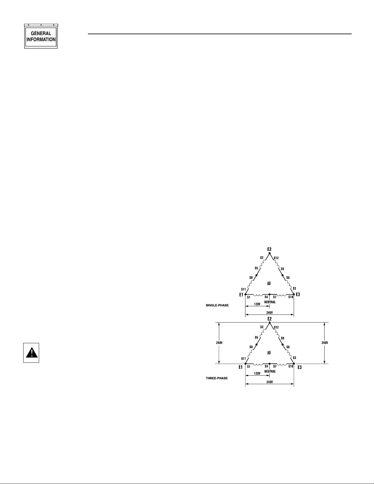
The generator was shipped from the factory with its stator AC output leads connected in one of the “Delta” configurations, as shown in Figure 2. This type of connection system will supply a 120 and/or 240 volts, 1 or
3-phase output as shown in the illustration.
Figure 2 - Generator AC Connection System
If, however, load voltage requires 120/208 volts, 3-phase
output, generator will require reconnecting of the stator’s output leads. This task should only be performed
by a qualified Generac service technician. Refer to the
installation manual (Part No. 079699) for details.
Section 1 - General Information
Guardian Liquid-cooled 10 kW, 15 kW, 20 kW and 25 kW Generators
Page 7
Generac®Power Systems, Inc. 5
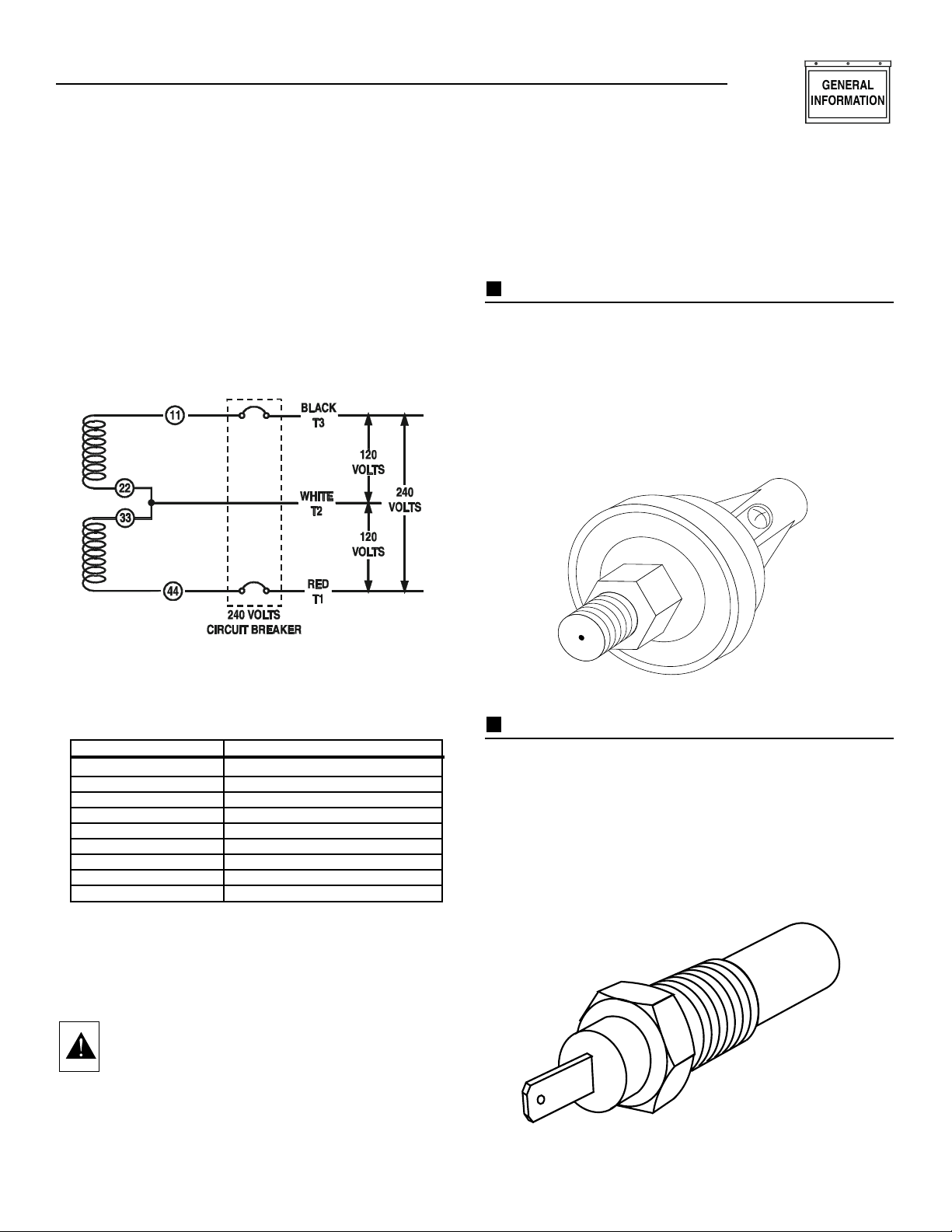
Figure 3 represents a single-phase, 3-wire generator AC
connection system. The stator assembly in this system
consists of a pair of stationary windings, with two leads
brought out of each winding. Each single winding can
supply 120 volts AC, 60 Hertz. When the two windings
are connected in series, a 240 volts, 60 Hertz AC output
results. Typically the two “hot” leads in the circuit are
Wires No. 11 and 44. The “Neutral” leads are the junction of Wires 22 and 33.
Figure 3 - Generator AC Connection System
MAIN CIRCU IT B R EAKER
The generator’s main circuit breaker is included with the unit as
shipped from the factory.The breaker for each unit is described as
follows:
GENERATOR F U EL SYSTEM
Your unit has been factory tested and adjusted using a
natural gas fuel system. If propane (LP) gas is preferred, contact an authorized service dealer.
WARNING: Gaseous fuels such as natural and LP
(propane) gas are highly explosive. Even the slightest
spark can ignite such fuels and cause an explosion. No
leakage of fuel is permitted. Natural gas, which is lighter
than air, tends to collect in high areas. LP gas is heavier
than air and tends to settle in low areas.
ENGINE P ROTECTIVE DEVICES
The engine has several safety switches which cause the
engine to automatically shut down under the following
conditions: low oil pressure, high coolant temperature,
engine overspeed, low coolant level or overcrank.
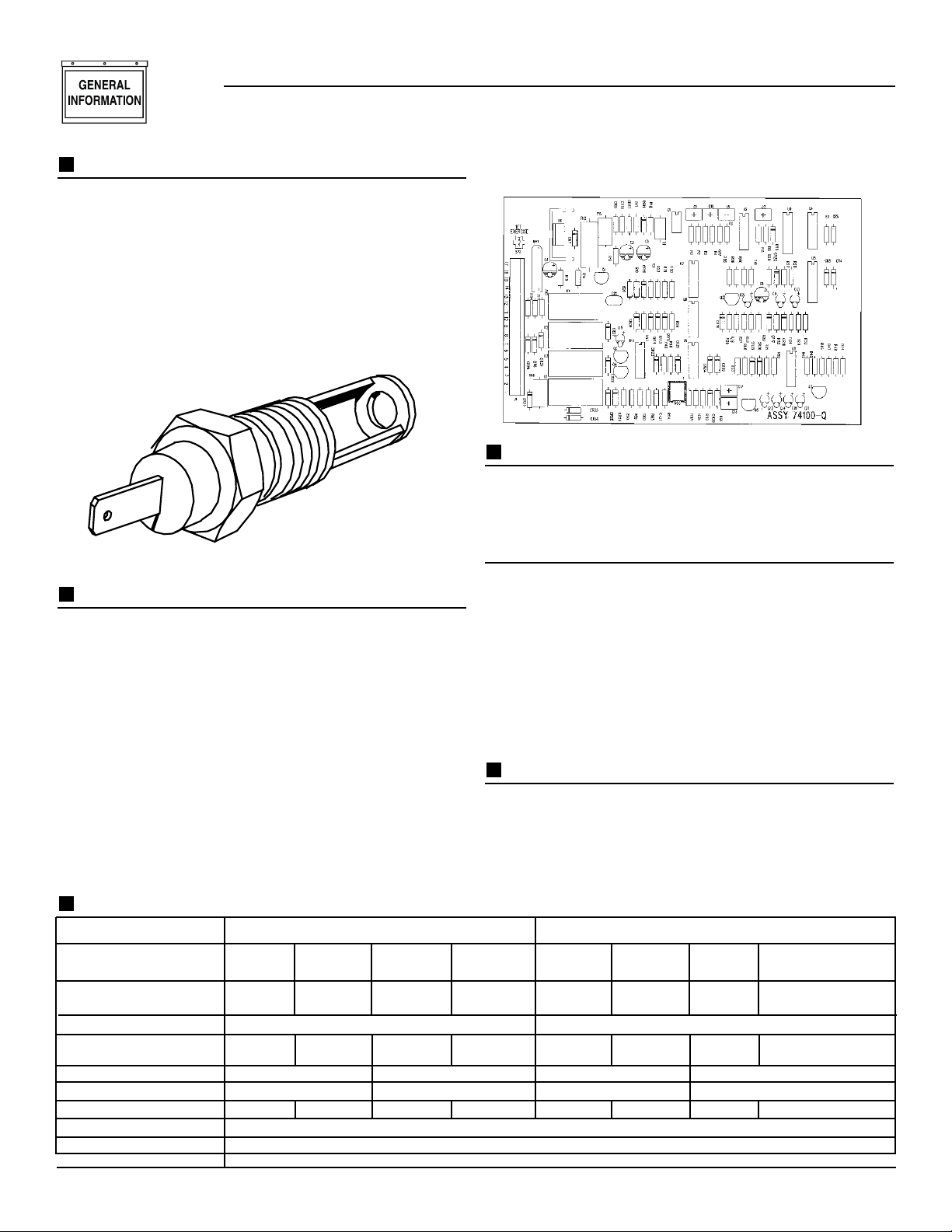
LOW OIL P R ESSURE SWITCH:
This switch is normally-closed (N.C.) but is held open
by engine oil pressure during engine running. Should
operating oil pressure drop below about 8-10 psi (55-68
kPa), the switch contacts close and the engine shuts
down automatically (Figure 4).
Figure 4 - Low Oil Pressure Switch
HIGH COOLANT TEMP ER ATURE SWITCH:
Normally open (N.O.) thermostatic switch has sensing
tip which is immersed in captive coolant. Should
coolant temperature exceed about 230°F (110°C), the
switch contacts close, which causes the engine to shut
down automatically (Figure 5).
Figure 5 - High Coolant Temperature Switch
Section 1 - General Information
Guardian Liquid-cooled 10 kW, 15 kW, 20 kW and 25 kW Generators
MODEL CIRCUIT BREAKER RATING
004090-2, 004124-1 50 amp BQ2 breaker
004091-2, 004125-1 40 amp BQ3 breaker
004092-2, 004128-1 90 amp BQ2 breaker
004093-2 70 amp BQ3 breaker
004094-2, 004126-1 70 amp BQ2 breaker
004095-2, 004127-1 60 amp BQ3 breaker
004096-2, 004130-1 125 amp BQ2 breaker
004097-2, 004131-1 90 amp BQ3 breaker
004474-0, 004475-0 125 amp BQ2 breaker
Page 8
6 Generac®Power Systems, Inc.
LOW COOLANT LEVEL SWITCH:
Should engine coolant level drop below the level of the
high coolant temperature switch, it is possible for the
engine to overheat without automatic shutdown. To
prevent such overheating without automatic shut down,
the engine has a low coolant level sensor. If the engine
coolant drops too low, the engine automatically shuts
down (Figure 6).
Figure 6 - Low Coolant Level Sensor
OVERSPEED SHUTDOWN:
The CMA circuit board on liquid cooled units receives
AC frequency (rpm) signals directly from the stator AC
power windings, via sensing leads S15 and S16. Should
AC frequency exceed about 72 Hz, circuit board action
will automatically shutdown the engine (Figure 7).
*Rated power of generator is subject to and limited by
such factors as ambient temperature, altitude, engine
condition, and other factors. Engine power will decrease
about 3.5% for each 1000 feet above sea level and will
decrease an additional 1% for each 10°F above 60°F.
Maximum output power of the generator is limited by
maximum engine power.
Figure 7 - Control Module Assembly Circuit Board
OVERCRANK SHUTDOWN:
After 90 seconds of crank-rest cycles, this function ends
cranking if the engine fails to start in that 90-second
span.
DC FUSE
This clearly labeled fuse is located on the front panel of
the control system. It protects the panel wiring and
components from damaging overload. Always remove
this fuse before commencing work on the generator.
The unit will not start or crank if the fuse is blown.
Replace the fuse with one of the same size, type, and rating. Generac normally uses an AGC fuse rated at 15
amps.
UNPACKING
UNPACKING PRECAUTIONS:
Handle shipping cartons and crates with care. Use care
to avoid damage from dropping, bumping, collision, etc.
Store and unpack cartons with the proper side up, as
noted on the shipping carton.
Section 1 — General Information
Guardian Liquid-cooled 10 kW, 15 kW, 20 kW and 25 kW Generators
SPECIFICATIONS
GENERATOR SPECIFICATIONS
3-Phase 1-Phase
Mode
l 004097 004095 004093 004091 004096† 004094 004092 004090
004131 004127 004125 004130† 004126 004128 004124
*Rated Max. Cont.
AC Power Output (kW) 25 20 15 10 25 20 15 10
Rated V oltage (volts) 120/208 120/240
Rated Max. Cont.
Current @ 240 V, 1Ø N/A N/A N/A N/A 104.2 83.3 62.5 41.6
Current @ 208 V, 3Ø 86.8 69.5 52.1 34.7 N/A N/A N/A N/A
No.of Rotor Poles 2 4 2 4
Driven Speed of Rotor 3600 3600 1800 1800 3600 3600 1800 1800
Rotor Excitation System Direct excited brush type system
Type of Stator 12 wire reconnectable
Rotor/Stator Insulation Class F
† Models 004474 & 004475 has same specifications
as models 004096 & 004130 below.
Page 9
INSPECTION:
After unpacking, carefully inspect the generator for any
damage that may have occurred during shipment. If
loss or damage is noted at the time of delivery, have the
person(s) making delivery note all damage on the freight
bill or affix his signature under the consignor’s memo of
loss or damage.
LIFTI NG TH E GEN ERATOR
WARNING: When lifting or hoisting equipment is used,
be careful not to touch overhead power lines.The generators weight of more than 900 pounds requires proper
tools, equipment, and qualified personnel to be used in
all phases of handling and unpacking.
SPECIFICATIONS
ENGINE SP ECIF ICATIONS
Make................................................................................Mitsubishi
Displacement ................................................92 inches
3
(1.5 liters)
Cylinder Arrangement ........................................................4, in-line
Valve Arrangement..................................................Overhead Cam
Firing Order..........................................................................1-3-4-2
Number of Main Bearings ............................................................5
Compression Ratio ................................................................9 to 1
No.of Teeth on Flywheel ..........................................................104
Ignition Timing
at 1800 rpm ....................................................35 degrees BTDC
at 3600 rpm ....................................................43 degrees BTDC
Spark Plug Gap....................................................0.020-0.025 inch
Recommended Spark Plugs
Champion......................................................................RN11YC4
Oil Pressure ......................................................................30-50 psi
Crankcase Oil Capacity..........................4.0 U.S. quar ts (3.8 liters)
Recommended Engine Oil..........................................SAE 15W-40
Type of Cooling System....................Pressurized, closed recovery
Cooling Fan ................................................................Pusher Type
Cooling System Capacity ........................2 U.S.gallons (7.6 liters)
Recommended Coolant..............................Use a 50-50 mixture of
ethylene glycol base.
FUEL CONSUM PTION
Models 004096, 004097, 004130, 004131, 004474, 004475
Using Natural Gas....................................441 cu. ft. per hour
Using LP Gas ........................175 cubic ft.(4.8 gal.) per hour
Models 004094, 004095, 004126, 004127
Using Natural Gas....................................359 cu. ft. per hour
Using LP Gas........................143 cubic ft. (4.0 gal.) per hour
Model 004092, 004093, 004128
Using Natural Gas....................................277 cu. ft. per hour
Using LP Gas ........................110 cubic ft.(3.1 gal.) per hour
Models 004090, 004091, 004124, 004125
Using Natural Gas....................................195 cu. ft. per hour
Using LP Gas..........................77 cubic ft. (2.2 gal.) per hour
NOTE:
Fuel consumption is given at rated maximum continuous power output when using natural gas rated
at 1000 Btu per cubic foot; or LP gas rated 2520
Btu per cubic foot. Actual fuel consumption
obtained may vary depending on such variables as
applied load, ambient temperature, engine conditions and other environmental factors.
TORQUE SP ECIF ICATIONS
Cylinder Head......................................15 (+ 90° + 90°) ft.lb.
Intake Manifold..........................................................13 ft.lb.
Exhaust Manifold ......................................................13 ft.lb.
ENGINE OI L R ECOMMEN DATIONS
The unit has been filled with 15W-40 engine oil at the
factory. Use a high-quality detergent oil classified “For
Service CC, SD, SE, SF.” Detergent oils keep the engine
cleaner and reduce carbon deposits. Use oil having the
following SAE viscosity rating, based on the ambient
temperature range anticipated before the next oil
change:
CAUTION: Any attempt to crank or start the
engine before it has been properly serviced with
the recommended oil may result in an engine
failure.
Section 1 — General Information
Guardian Liquid-cooled 10 kW, 15 kW, 20 kW and 25 kW Generators
Generac®Power Systems, Inc. 7
Temperature Oil Grade (Recommended)
Above 80° F (27° C) SAE 30W or 15W-40
32° to 80° F (-1° to 27° C) SAE 20W-20 or 15W-40
Below 32° F (0° C) SAE 10W or 15W-40
Page 10

8 Generac®Power Systems, Inc.
BEFORE I NSTALLATION
Before installing this equipment, check the ratings of
both the generator and the transfer switch. Read
“Emergency Isolation Method” and “Total Circuit
Isolation Method” in the installation manual (Part No.
079699).
The generator’s rated wattage/amperage capacity must
be adequate to handle all electrical loads that the unit
will power. You may have to group the critical (essential)
loads together and wire them into a separate “emergency” distribution panel.
This generator can be installed in conjunction with a
standard Generac “GTS” type transfer switch, if
desired.
The standard transfer switch has no sensing or controlling circuit boards. Instead, the generator control
console houses a “Control Module Assembly”, which
controls all phases of operation, including engine start
up and load transfer.
Section 1 — General Information
Guardian Liquid-cooled 10 kW, 15 kW, 20 kW and 25 kW Generators
Page 11
Generac®Power Systems, Inc. 9
If an open bottom is used, the engine-generator is
to be installed over non-combustible materials
and should be located such that combustible
materials are not capable of accumulating under
the generator set.
Only qualified, competent installation contractors or
electricians thoroughly familiar with applicable codes,
standards and regulations should install this standby
electric power system. The installation must comply
strictly with all codes, standards and regulations pertaining to the installation.
After the system has been installed, you must not do
anything that might render the installation in noncompliance with such codes, standards and regulations.
NOTE:
For more information about the installation of a standby system, you can order Engine- Generator Standby
Electric Power Systems Installer’s Guide and
Reference Manual (part #46622) from your Generac
Authorized Service Dealer.
NFPA STANDARDS
The following published standards booklets pertaining
to standby electric systems are available form the
National Fire Protection Association (NFPA),
Batterymarch Park, Quincy, MA 02269:
• NFPA No. 37, ST A TIONARY COMBUSTION ENGINES
AND GAS TURBINES.
• NFPA No. 76A, ESSENTIAL ELECTRICAL SYSTEMS
FOR HEALTH CARE FACILITIES.
• NFPA No. 220, STANDARD TYPES OF BUILDING
CONSTRUCTION
• NFPA No. 68, GUIDE FOR EXPLOSION VENTING
• NFPA No. 70, NATIONAL ELECTRICAL CODE.
• NFPA No. 30, FLAMMABLE AND COMBUSTIBLE
LIQUIDS CODE.
• NFPA No. 10, INSTALLATION, MAINTENANCE AND
USE OF PORTABLE FIRE EXTINGUISHERS.
OTHER PUBLISH ED STANDARDS
In addition to NFPA standards, the following information pertaining to the installation and use of standby
electric systems is available:
• Article X, NATIONAL BUILDING CODE, available
from the American Insurance Association, 85 John
Street, New York, N.Y. 10038.
• AGRICULTURAL WIRING HANDBOOK, obtainable
from the Food and Energy Council, 909 University
Avenue, Columbia, MO, 65201.
• ASAE EP-364.2, INSTALLATION AND MAINTENANCE OF FARM STANDBY ELECTRIC POWER,
available from the American Society of Agricultural
Engineers, 2950 Niles Road, St. Joseph, MI 49085.
• A52.1, AMERICAN NATIONAL STANDARD FOR
CHIMNEYS, FIREPLACES AND VENTING SYSTEMS, available from the American National
Standard Institute, 1430 Broadway, New York, N.Y.
10018.
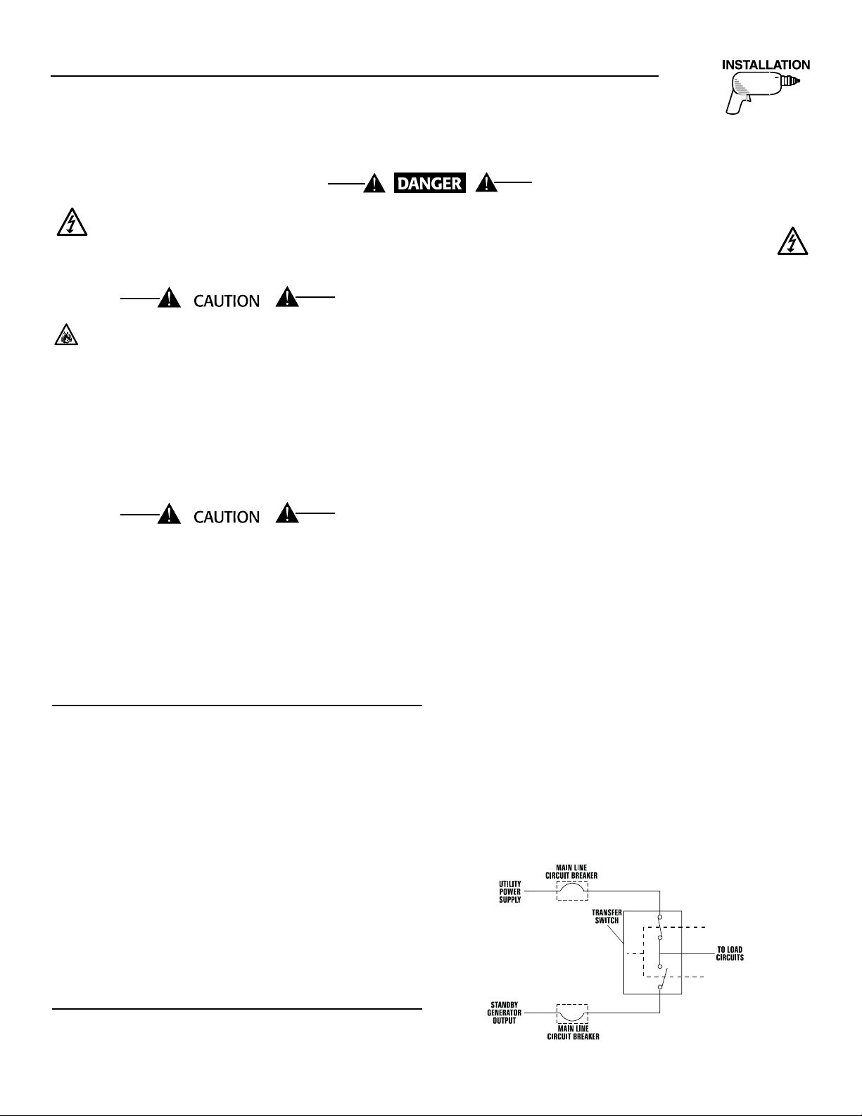
BASIC STANDBY ELECTRIC SYSTEM
Figure 2.1 shows a schematic diagram of a basic standby electric system. Both the UTILITY power supply and
the STANDBY (generator) output are connected to an
approved transfer switch. The transfer switch is
required by electrical code and serves the following
functions:
• Permits the LOAD circuits to be connected to only one
power supply at a time.
• Prevents electrical backfeed between the generator
and the UTILITY power circuits.
Notice that both the STANDBY and the UTILITY power
supplies to the transfer switch are protected against
overload by a main line circuit breaker.
NOTE:
Generac recommends the use of a Generac power
systems “GTS” type transfer switch in conjunction
with this generator.
Figure 2.1 – Basic Standby Electric System
◆
◆
Section 2 — Installation
Guardian Liquid-cooled 10 kW, 15 kW, 20 kW and 25 kW Generators
STAN DBY GENER ATOR INSTALLATION
Connecting this generator to an electrical system normally supplied by an electric utility shall be by
means of a transfer switch (such as the Generac “GTS” type transfer switch), so as to isolate the electric
system from the utility distribution system when the generator is operating. Failure to isolate the
electric system by these means will result in damage to the generator and may also result in injury
or death to utility workers due to backfeed of electrical energy.
Page 12
10 Generac®Power Systems, Inc.
EMERGENCY CIRCU IT
ISOLATION METHOD
This prevents overloading the generator by keeping electrical loads below the wattage/amperage capacity of the
generator. If the generator is powering only critical
loads, within the wattage/amperage capacity, during utility power outages, you might consider using the emergency circuit isolation method.
Critical electrical loads are grouped together and wired
into a separate “Emergency Distribution Panel.” Load
circuits powered by that panel are within the
wattage/amperage capacity of the generator set. When
this method is used, it is difficult to overload the generator. The transfer switch must meet the following
requirements:
• It must have an ampere rating equal to the total
amperage rating of the emergency distribution panel
circuit.
• Have it installed between the building’s main distribution panel and the emergency distribution panel.
TOTAL CI RCU IT ISOLATION METHOD
When a generator capable of powering all electrical
loads in the circuit is to be installed, you may use the
“Total Circuit Isolation Method.” It is possible for the
generator to be overloaded when this isolation method
is employed. The following apply to the transfer switch
in this type of system.
• Ampere rating of the transfer switch must equal the
ampere rating of the normal incoming utility service.
• The transfer switch is installed between the utility
service entrance and the building distribution panel.
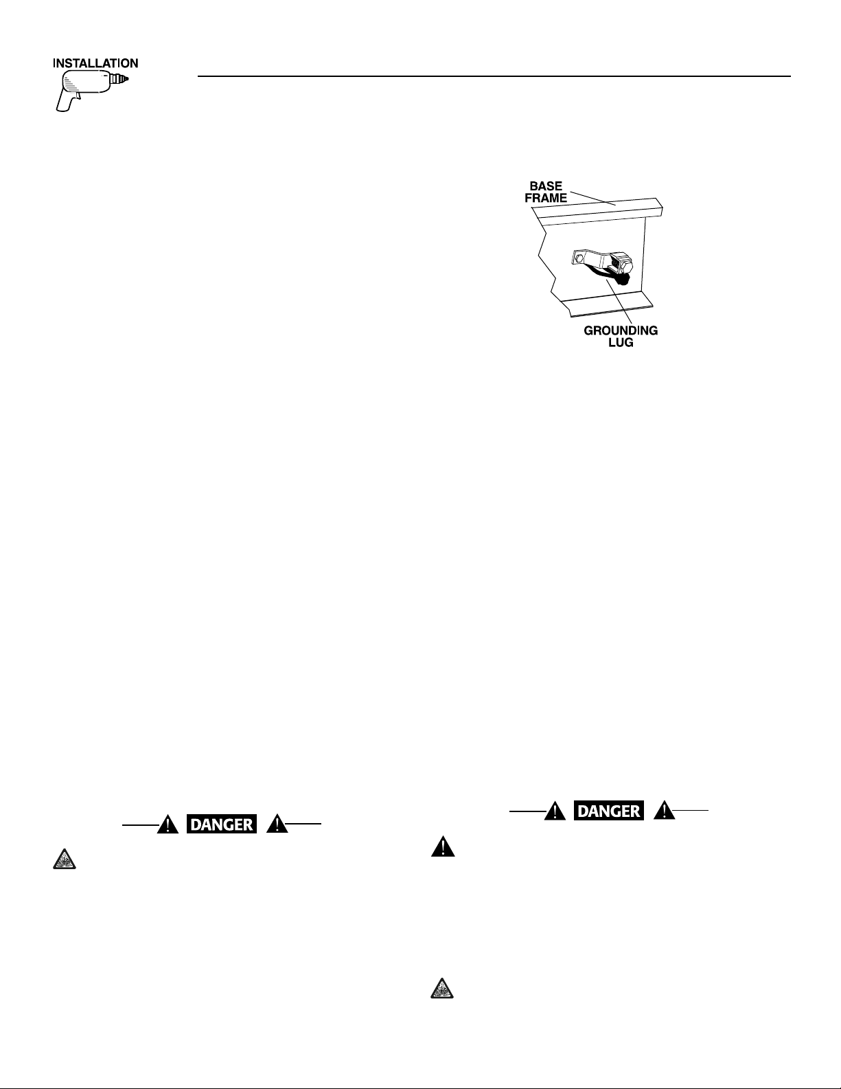
GROUNDI NG TH E GEN ERATOR
The National Electrical Code requires the frame and
external electrically conductive parts of this equipment
to be properly connected to an approved earth ground
and/or grounding rods. For that purpose, a GROUND
LUG (Figure 2.2) is provided on the generator mounting
base. Consult a qualified electrician for grounding
requirements in your area. Grounding procedures must
meet local regulations.
Do not connect the ground wire to any pipe that
carries a flammable or explosive substance – FIRE
or an EXPLOSION may result.
Proper grounding helps protect personnel against electrical shock in the event of a ground fault condition in the
generator or in connected electrical devices. In addition,
grounding helps dissipate static electricity that often
builds up in ungrounded devices.
Figure 2.2 – Generator Grounding Lug (typical)
GENERATOR AC
NEUTRAL CONN ECTIONS
Generac uses an UNGROUNDED AC neutral. Grounding
is recommended only at the main service entrance. If the
neutral wire is grounded and one of the phase loads
becomes grounded, the excessive current opens the load
circuit breaker or collapses the generator field. The actual result depends on the electrical characteristics of the
particular installed generator.
TRANSFER SWITCH START
SIGNAL CONNECTIONS
If your generator is to be installed with an automatic
transfer switch, such as a Generac GTS-type switch, it
will be necessary to connect the two-wire start
control system.
Connect the two-wire start signal from the automatic
transfer switch to the automatic start connection, which is
located in the right hand corner of the control panel.
Match wires 178 and 183 in the transfer switch to 178
and 183 on the terminal strip in the control panel. The
conductors for the two-wire start circuit must be in their
own conduit.
BAT TERY INSTALLATION
Standby generators installed with automatic transfer switches will crank and start automatically
when normal (utility) source voltage is removed or
is below an acceptable preset level. To prevent
such automatic start-up and possible injury to personnel, do not connect battery cables until you are
certain that normal source voltage at the transfer
switch is correct and you are ready to place the
system into operation.
Storage batteries give off explosive hydrogen gas.
This gas can form an explosive mixture around
the battery for several hours after charging. The
slightest spark can ignite the gas and cause
Section 2 — Installation
Guardian Liquid-cooled 10 kW, 15 kW, 20 kW and 25 kW Generators
Page 13
Generac®Power Systems, Inc. 11
an explosion. Such an explosion can shatter the battery and cause blindness or other injury. Any area that
houses a storage battery must be properly ventilated.
Do not allow smoking, open flame, sparks or any spark
producing tools or equipment near the battery.
Battery electrolyte fluid is an extremely caustic
sulfuric acid solution that can cause severe burns.
Do not permit fluid to contact eyes, skin, clothing,
painted surfaces, etc. Wear protective goggles,
protective clothing and gloves when handling a
battery. If you spill the fluid, flush the affected
area immediately with clear water.
Do not dispose of the battery in a fire. The
battery is capable of exploding.
Do not open or mutilate the battery. Released
electrolyte can be toxic and harmful to the skin
and eyes.
The battery represents a risk of high short circuit
current. When working on the battery, always
remove watches, rings or other metal objects, and
only use tools that have insulated handles.
VENTED BATTERIES
The electrolyte is a dilute sulfuric acid that is
harmful to the skin and eyes. It is electrically conductive and corrosive. The following procedures
are to be observed:
• Wear full eye protection and protective clothing,
• Where electrolyte contacts the skin, wash it off
immediately with water,
• Where electrolyte contacts the eyes, flush thoroughly
and immediately with water and seek medical attention, and
• Spilled electrolyte is to be washed down with an acidneutralizing agent. A common practice is to use a
solution of one pound (500 grams) bicarbonate of
soda to one gallon (4 liters) of water. The bicarbonate
of soda solution is to be added until the evidence of
reaction (foaming) has ceased. The resulting liquid is
to be flushed with water and the area dried.
Lead acid batteries present a risk of fire because
they generate hydrogen gas. The following procedure are to be followed:
• DO NOT SMOKE when near batteries,
• DO NOT cause flame or spark in battery area, and
• Discharge static electricity from body before touching
batteries by first touching a grounded metal surface.
Servicing of batteries is to be performed or supervised
by personnel knowledgeable of batteries and the
required precautions. Keep unauthorized personnel
away from batteries.
For recommended batteries, see “Specifications.” All
batteries must be at 100 percent state- of-charge before
they are installed on the generator.
When using maintenance-free batteries, it is not necessary to check the specific gravity or electrolyte level.
Have these procedures performed at the intervals specified in Section 4, “Maintenance.” A negative ground system is used. Battery connections are shown on the
wiring diagrams. Make sure all batteries are correctly
connected and terminals are tight. Observe battery
polarity when connecting batteries to the generator set.
Note:
Damage will result if the battery connections are
made in reverse.
PREPARATION BEFORE START-UP
The instructions in this section assume that the standby
generator has been properly installed, serviced, tested,
adjusted and otherwise prepared for use by a competent,
qualified installation contractor. Be sure to read the
“Safety Rules” on Pages 2 and 3, as well as all other safety information in this manual, before attempting to
operate this (and related) equipment.
PRIOR TO INITIAL START-UP
Prior to initially starting the generator, it must be
properly prepared for use. Any attempt to crank
or start the engine before it has been properly
serviced with the recommended types and quantities of engine fluids (oil, coolant, fuel, etc.) may
result in an engine failure.
Before starting the generator for the first time, the
installer must complete the following procedures. For
follow-up maintenance information and/or service intervals, please refer to Section 4, “Maintenance,” and the
“Service Schedule” on Page 17.
Transfer Switch
If this generator is used to supply power to any electrical system normally powered by an electric utility, the
National Electrical Code requires that a transfer switch
be installed. The transfer switch prevents electrical
backfeed between two different electrical systems.
(For additional information, see the applicable transfer
switch manual for this unit.) The transfer switch, as
well as the generator and other standby components,
must be properly located and mounted in strict compliance with applicable codes, standards and regulations.
▼
◆
Section 2 — Installation
Guardian Liquid-cooled 10 kW, 15 kW, 20 kW and 25 kW Generators
Page 14
12 Generac®Power Systems, Inc.
Fuel System
Make sure the fuel supply system to the generator (a)
delivers the correct fuel at the correct pressure and (b)
is properly purged and leak tested according
to code. No fuel leakage is permitted. See
“Specifications” (Page 7) for more information.
If the unit has been idle for a long period of time, or if
the fuel lines or system components have been removed
and reinstalled, the fuel system may require bleeding to
remove air from the system. Air in the fuel system
causes hard starting and rough operation. All fuel
system lines must be installed and must be tight. A
loose line may show no sign of leakage, but may draw
air into the system.
Use a suitable container to catch the fuel that will
spill during system bleeding process. Clean up all
spilled fuel after bleeding.
Generator Set Lubrication
Check the engine crankcase oil level before operating
and add oil to the proper level – the dipstick “FULL”
mark. Never operate the engine with the oil level below
the dipstick “ADD” mark. See “Specifications” (Page 7)
and “Engine Oil Recommendations” (Page 8).
NOTE:
This engine is shipped from the manufacturer with
15W-40 oil. This oil should be changed after 30
hours of operation.
Check the oil level in the generator gearbox (If so
equipped, contact sales for availability.) prior to initial
use and at the intervals indicated by the “Service
Schedule.” The recommended oil is SAE 90 gear lubricant.
Also, if the engine is equipped with a mechanical governor, make sure the governor is properly lubricated with
clean engine oil.
Engine Coolant
Have the engine cooling system properly filled with the
recommended coolant mixture. Check the system for
leaks and other problems. See “Specifications” (Page 7)
and “Coolant” (Page 8).
Belt Tension
Check the engine fan belt tension and condition prior to
placing the unit into service and at recommended
intervals. Belt tension is correct when a force of approximately 22 pounds (10 kg), applied midway between
pulleys, deflects the belt about 3/8- to 5/8-inch
(10 to 16 mm).
Electrical System
Make sure the generator is properly connected to an
approved earth ground.
Make sure the generator battery is fully charged, properly installed and interconnected, and ready for use.
Check to ensure that there are no loose electrical connections. Restrain any loose wires to keep them clear of
any moving generator set components.
USING A STANDARD “GTS” TR ANSFER
SWITCH
When required, the pre-packaged standby generator
can be installed with a standard Generac “GTS” type
automatic transfer switch.
When you use a standard GTS type transfer switch, it
controls automatic operation and automatic transfer as
follows:
• Solid state circuits in the transfer switch monitor utility power source voltage.
• When utility source voltage drops below a pre-set
level, transfer switch action closes the circuit. The
engine then cranks and starts as controlled by the
pre-packaged generator’s Control Module circuit
board.
• After the engine starts and when the generator AC
output voltage and frequency have reached a pre- set
value, transfer switch circuits signal the transfer
switch main contacts to actuate to the “Standby”
power source side. Generator AC output then powers
load circuits.
• When the utility power source voltage is restored
above a pre- set level, transfer switch solid state circuits signal the switch main contacts to move back to
their utility power source side.
• Following re-transfer back to the utility power source
side, transfer switch circuit board action opens the
circuit. Engine then shuts down.
NOTE:
If your generator is installed in conjunction with a
standard GTS type transfer switch, refer to the
applicable transfer switch manual for exact operating parameters and timing sequences.
▼
▼ ▼ ▼ ▼
Section 3 — Operation
Guardian Liquid-cooled 10 kW, 15 kW, 20 kW and 25 kW Generators
Page 15
Generac®Power Systems, Inc. 13
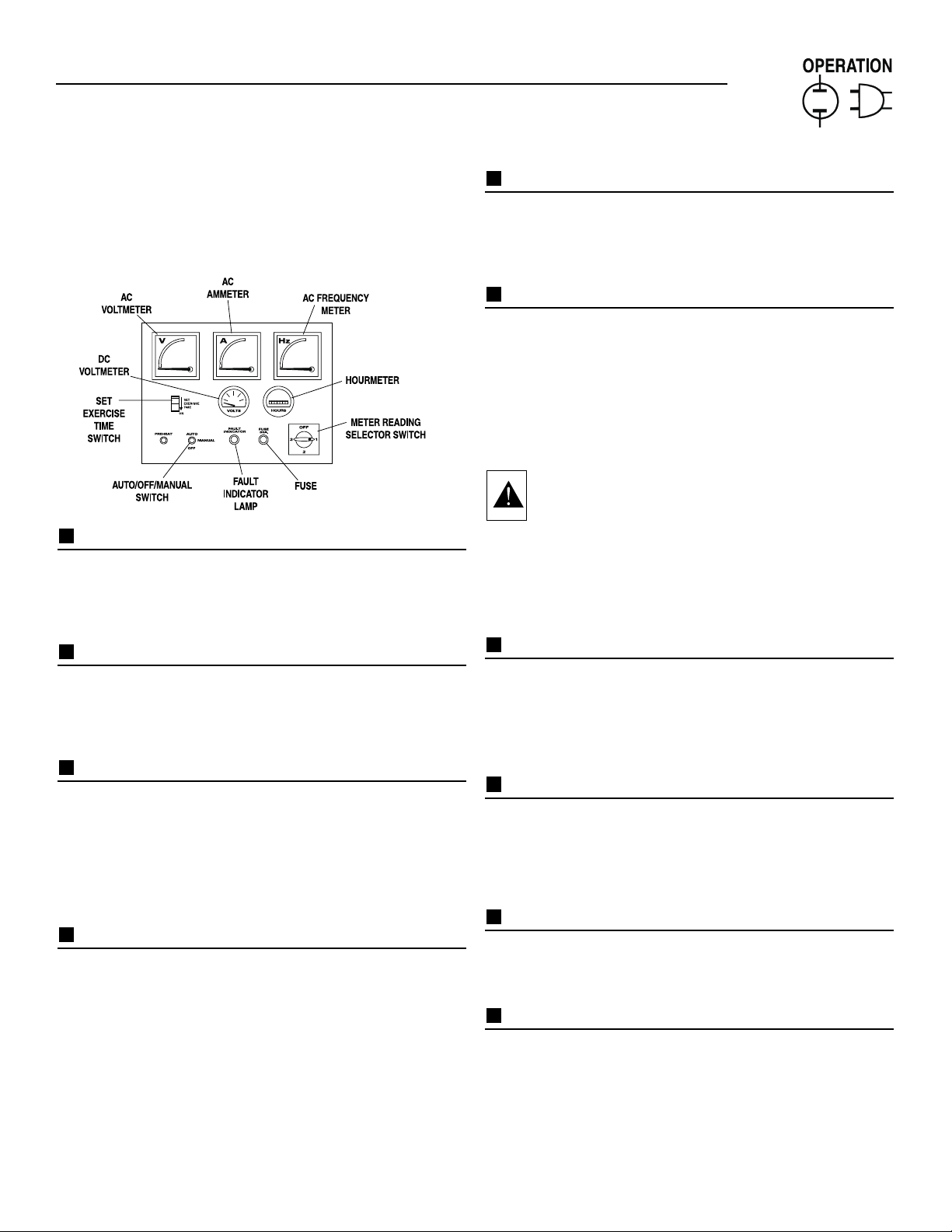
CONTROL CONSOLE COMPONENTS
The components of a water-cooled generator control
console (Figure 8) are as follows:
Figure 8 - Water-Cooled Generator Panel
AC VOLTM ETER:
The voltmeter displays generator AC output voltage during operation. Voltage is regulated by a solid state voltage regulator and is proportional to AC frequency. Refer
to your unit’s DATA PLATE for rated AC voltage.
AC AMMETER:
Indicated current draw of connected electrical loads
during operation. DO NOT EXCEED YOUR UNIT’S
RATED MAXIMUM CONTINUOUS CURRENT. Refer to
the unit DATA PLATE.
AC FREQUENCY METER:
Indicates generator AC output frequency in “Hertz”
(cycles per second). F requency is proportional to engine
speed. Units with a 4-pole rotor supplies 60 Hertz at
1800 rpm. Units with a 2-pole rotor supplies 60 Hz at
3600 rpm. Frequency reading with no electrical loads
connected (no-load condition) should be between 59-61
Hertz.
DC VOLTMETER:
The generator is equipped with a belt-driven DC
alternator, which maintains battery state of charge when
the engine operates. The Control Module Assembly also
incorporates a trickle charge circuit which maintains
battery state of charge during non-operating periods.
Battery voltage should read about 12.5 to 14.5 volts DC.
A low battery voltage indicates the battery is
discharging.
HOURMETER:
Indicates time the engine-generator has operated, in
hours and tenths of hours. Use the hourmeter along
with the periodic maintenance schedule for your generator set.
AUTO/OFF/MAN UAL SWITCH:
Use this 3-position switch as follows:
• Set the switch to “Auto” for fully automatic operation.
See “Automatic Operation”.
• Set switch to “Manual” position to crank and start the
generator engine.
• Set switch to “Off ” position to shut down an operating engine. With “Off” selected, operation will not be
possible.
DANGER! With switch set to "auto", engine can
crank and start suddenly without warning. Such
automatic start up normally occurs when utility
source voltage drops below a pre-set level. To
prevent possible injury that might be caused by
such sudden starts, set AUTO/OFF/MANUAL
switch to "off" before working on or around the
unit. Then, place a "do not operate" tag on control console.
FAULT INDICATOR LAM P:
Lamp goes ON when one or more of the following
engine faults occurs and when engine shuts down.
• Low oil pressure • Overcrank
• High coolant temperature • Overspeed
• Low coolant level
30 AMP FUSE:
Fuse protects the control console’s DC control circuit
against electrical overload. If the fuse has melted open
because of an overload, engine cranking and startup
cannot occur. Should you need to replace the fuse, use
only an identical 30-amp replacement fuse. (Type AGC)
METER READING SELECTOR SWITCH:
Switch permits you to select either line-to-line or
line-to-neutral voltage and amperage readings on the
console AC voltmeter and AC ammeter.
SET EXERCISE TIME SWITCH:
Switch allows you to program the generator to start and
exercise automatically. “See Weekly Exercise Cycle.”
MANUAL TRANSFER AN D START UP
To transfer electrical loads to the “Standby” (generator)
power source side and start the engine manually, refer
to the Owner’s Manual of your particular transfer
switch.
Section 3 - Operation
Guardian Liquid-cooled 10 kW, 15 kW, 20 kW and 25 kW Generators
Page 16
14 Generac®Power Systems, Inc.
RETRANSFER AN D SH UTDOWN
When utility power source voltage has been restored,
electrical loads may be transferred back to that source
and the generator can be shut down as follows:
• Verify that utility power supply voltage to the transfer
switch has been positively turned “Off,” using whatever means provided (such as utility main line circuit
breaker).
• Set the generator’s main circuit breaker to its “Off” or
“Open” position.
• Let the generator engine run at no-load for a few minutes, to stabilize internal unit temperatures.
• On the generator console, set the Auto-Off-Manual
switch to “Off ”. Wait for engine to come to a complete stop.
• For transfer to utility position, refer to the Owner’s
Manual of your particular transfer switch.
• Turn on the utility power supply to the transfer
switch, using whatever means provided (such as a
utility main line circuit breaker). The utility power
source now powers the loads.
AUTOMATIC OPERATION
To set the system for fully automatic operation, proceed
as follows:
• Check that load circuits are connected to the
utility power supply.
• Set the Auto/Off/Manual switch to its “Auto” position.
• Set the generator main circuit breaker to its “On” or
“Closed” position.
WEEKLY EXERCISE CYCLE
The generator will start and exercise once every 7 days.
During this weekly exercise, the unit runs for about 20
minutes and shuts down. Transfer of loads to generator output does not occur during the exercise.
To select day and time for exercising, proceed as follows:
• Set the Auto/Off/Manual switch to OFF.
• Set generator main circuit breaker to OFF or OPEN.
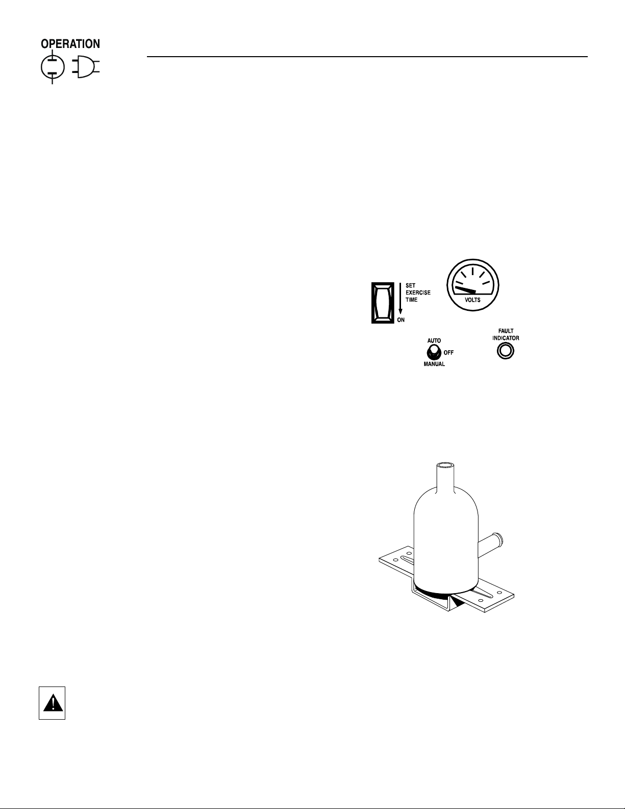
• Locate the rocker switch on the control panel identified with the words “Set Exercise Time” (Figure 9).
• Push “Set Exercise Time” switch to ON position for
20 to 30 seconds and then release. Switch will spring
back into its original position when released.
• Wait 30 seconds before setting the Auto/Off/Manual
switch to “AUTO” position.
CAUTION: If you switch the Auto/Off/Manual
switch too soon, the engine may start. If engine
does start, it will shut down automatically in
about two (2) minutes.
• Set the generator main circuit breaker to its ON or
CLOSED position.
• Generator is now programmed to start and exercise
every 7 days thereafter, on day and time of day the
switch was actuated.
• Place a sign on the generator control panel and the
transfer switch, indicating the day and time the generator will be exercising.
NOTE:
If battery terminals are disconnected or control
panel fuse is removed, the exercise timer needs to
be reset for correct automatic exercise operation.
Figure 9 - “Set Exercise” Switch
ENGINE H EATER
Your Generac standby generator comes equipped with a
block heater (Figure 10), similar to the block heaters
used in automotive applications.
Figure 10 - Engine Block Heater
Refer to applicable wiring diagram(s) and electrical schematic(s) at
back of manual for wiring connections.
Section 3 — Operation
Guardian Liquid-cooled 10 kW, 15 kW, 20 kW and 25 kW Generators
Page 17

Generac®Power Systems, Inc. 15
MAINTENANCE PER FOR M ED BY
AUTHORIZED SERVICE FACILITI ES
A. EVERY THREE MONTHS
1.Check battery state of charge and condition.
2.Inspect and test fuel system.
3.Check transfer switch.
4.Inspect exhaust system.
5.Check engine ignition system.
6.Check fan belts.
B. ONCE EVERY SIX MONTHS
1.Test Engine Safety Devices (low oil pressure, low
coolant level, high coolant temperature).
C. ONCE ANNUALLY
1.Test engine governor; adjust or repair, if needed.
2.Clean, inspect generator.
3.Flush cooling system.
D. FIRST 100 OPER ATING HOURS
1.Change engine oil and oil filter . (After initial change,
service engine oil and filter at 150 operating hours
or 6 months, whichever comes first.)
2.Retorque cylinder head. (See Torque Specs, page 7.)
3.Retorque intake and exhaust manifold. (See Torque
Specs, page 7.)
E. EVERY 500 OPERATING HOU RS
1.Service air cleaner.
2.Check starter.
3.Check engine DC alternator.
F. EVERY 800 OPERATING HOURS
1.Retorque cylinder head. (See Torque Specs, page 7.)
2.Retorque intake and exhaust manifold. (See Torque
Specs, page 7.)
3.Check engine compression.
4.Check valve clearance.
OVERLOAD PROTECTION FOR ENGI NE DC
ELECTRICAL SYSTEM
Engine cranking, start up and running are controlled by
a solid state Engine Controller circuit board. Battery
voltage is delivered to that circuit board via a 30 amp
fuse. These overcurrent protection devices will open if
the circuit is overloaded.
CAUTION! If a circuit breaker opens or a fuse
element melts, you should find the cause of the
overload before resetting the circuit breaker or
replacing the fuse.
CHECKING FLUI D LEVELS
CHECK ENGINE OI L
Check engine crankcase oil level (Figure 11) at least
every 20 hours of operation, or prior to use.
• Remove oil dipstick and wipe dry with a clean,
lint-free cloth.
• Install oil dipstick, then remove again.
• Oil should be between FULL and ADD marks.
• If oil level is below the dipstick ADD mark, remove oil
fill cap. Add the recommended oil to bring oil level
up to the FULL mark. DO NOT FILL ABOVE THE
“FULL” MARK. See page 6 for recommended oils.
Figure 11 - Oil Dipstick and Oil Fill Cap
c
ap
BATTERY FLUID
Check battery electrolyte fluid at least once weekly.
Fluid should cover separators in all battery cells. If
fluid level is low , add distilled water to cover tops of separators. DO NOT USE TAP WATER IN BATTERY.
ENGINE COOLANT
Check coolant level in coolant recovery bottle. See
Specifications, page 7
• Add recommended coolant mixture as necessary.
• Periodically remove radiator pressure cap to make
sure the coolant recovery system is functioning properly. Coolant should be at bottom of radiator filler
neck. If coolant level is low, inspect gasket in radiator pressure cap. Replace cap, if necessary. To have
pressure cap tested, contact an authorized Generac
Service Facility. Inspect cooling system and coolant
recovery system for leaks.
K
Section 3 — Maintenance
Guardian Liquid-cooled 10 kW, 15 kW, 20 kW and 25 kW Generators
OIL FILL CAP
OIL DIPSTIC
Page 18

16 Generac®Power Systems, Inc.
MAINTENANCE OWNER/OPER ATOR CAN
PERFORM
CHECK ENGINE OI L LEVEL
Refer to “Checking Fluid Levels” on page 15.
CHECK BATTERY
• Check battery fluid level each week as outlined under
“Check Fluid Levels”.
• Check battery cables for condition, tightness, corrosion or damage. Clean, tighten or replace as
necessary.
EXERCISE SYSTEM
Start the generator engine at least once every seven days
and let it run at least 20 minutes. See page 14, “Weekly
Exercise Cycle”.
INSPECT COOLING SYSTEM
• Inspect engine cooling system at least once each
month.
• Check hoses for damage, deterioration, leaks, etc.
Correct any discrepancies found.
• Check hose clamps for tightness.
CHECK ENGINE COOLANT LEVEL
See “Checking Fluid Levels” on page 15.
PERFOR M VISUAL INSP ECTION
Complete a thorough visual inspection of the entire
engine-generator monthly. Look for obvious damage,
loose, missing or corroded nuts, bolts and other fasteners. Look for fuel, oil or coolant leaks.
INSPECT EXHAUST SYSTEM
Inspect the exhaust system at least once every three
months. Check all exhaust system pipes, mufflers,
clamps, etc. for condition, tightness, leaks, security,
damage.
CHECK FAN BELT
• Inspect fan belts every three months. Replace any
damaged, deteriorated, worn or otherwise defective
belt.
• Check fan belt tension. Thumb pressure, exerted
midway between pulleys, should deflect about 3/8 to
3/4 inch. Adjust belt tension as required.
INSPECT ENGIN E GOVERNOR
Visually inspect electronic governor.
DANGER: Do not attempt to adjust the governor. Only qualified service facilities should
adjust the governor. Excessively high operating
speeds are dangerous and increase the risk of
personal injury. Low speeds impose a heavy
load on the engine when adequate engine
power is not available and may shorten engine
life. Correct rated frequency and voltage are
supplied only at the proper governed speed.
Some connected electrical load devices may be
damaged by incorrect frequency and/or voltage.
Only qualified service technicians should adjust
the governed speed.
CHANGING ENGIN E OI L
Refer to maintenance performed by authorized service
facilities for engine oil and filter change frequencies.
Drain the oil while the engine is still warm from running. This means warm up the engine, shut it down and
drain immediately as follows:
1.Remove OIL DRAIN HOSE from its retaining clip.
2.Loosen and remove OIL DRAIN HOSE CAP. Drain
oil completely into suitable container.
3.When all oil has drained, install and tighten OIL
DRAIN HOSE CAP, and re-install into its retaining
clip.
4.Turn OIL FILTER (Figure 12) counterclockwise and
remove. Dispose of old filter.
Figure 12 - Oil Filter
5.Apply light coating of new engine oil to seal of new
oil filter. Install FILTER and tighten by hand only.
DO NOT OVERTIGHTEN.
6.Remove OIL FILL CAP (Figure 11, page 15). Add
recommended oil (see SPECIFICATIONS). DO NOT
FILL ABOVE THE DIPSTICK “FULL” MARK.
Crankcase oil capacity is 4.0 U.S. quarts (3.8 liters)
Section 3 — Maintenance
Guardian Liquid-cooled 10 kW, 15 kW, 20 kW and 25 kW Generators
OIL FILTER
Page 19
Generac®Power Systems, Inc. 17
CAUTION: After refilling the crankcase with oil,
always check oil level on dipstick. NEVER
OPERATE ENGINE WITH OIL BELOW THE DIPSTICK “ADD” MARK.
7.Start engine and check for oil leaks.
COOLANT CHANGE
Every year, have Authorized Service Facility drain, flush
and refill the cooling system. See SPECIFICATIONS
(page 7) for cooling system recommendations.
MISCELLANEOUS MAI NTENANCE
CLEANING TH E GEN ERATOR
Keep your generator as clean and as dry as possible.
Dirt and moisture that accumulates on internal generator windings have an adverse effect on insulation resistance.
Periodically clean generator exterior surfaces. A soft
brush may be used to loosen caked on dirt. You can use
a vacuum system or dry, low pressure air to remove any
accumulations of dirt. The generator is housed inside
an all-weather enclosure, clean the enclosure with a
soft, damp cloth or sponge and water.
Once each year have the generator cleaned and inspected by an Authorized Service Facility. That facility will
use dry, low pressure air to clean internal windings.
Parts inside the control console should be cleaned and
inspected at this time as well.
Finally, have the insulation resistance of stator and
rotor windings checked. If insulation resistances are
excessively low, the generator may require drying.
BATTERY
All lead-acid storage batteries discharge when not in
use. Refer to specific instructions and warnings that
accompany your battery. If such information is not
available, observe the following precautions when
handling a battery:
• DO NOT use jumper cables and a booster battery to
crank or start the generator engine.
• DO NOT recharge a weak battery while it is installed
in the generator. Remove battery from generator and
recharge in a well-ventilated area, away from fuel
vapors, sparks, heat or flames.
• Battery electrolyte fluid is an extremely caustic
sulfuric solution that can cause severe burns. DO
NOT permit fluid to contact eyes, skin, clothing,
painted surfaces, wiring insulation, etc. If you spill
any battery fluid, flush the affected area with clear
water immediately.
• Always wear safety glasses, rubber apron and gloves
when handling a battery.
• Batteries give off explosive hydrogen gas while
charging. The gas can form an explosive mixture
around the battery for several hours after charging.
Any spark, heat or flames can ignite the gas and
cause an explosion which can shatter the battery,
causing blindness or other serious injury.
BATTERY REPLACEMENT
Generac uses these different types of vented batteries on
units ranging up to 400 kW. When replacing batteries,
use the same number and the type of battery that
follows:
Note:
The BCI number should be located directly
on the battery. For more information, see
“Specifications.”
Section 3 — Maintenance
Guardian Liquid-cooled 10 kW, 15 kW, 20 kW and 25 kW Generators
Generac P/N BCI Group No. CCA
58665 27F 700 @ 0 deg. F
61915 4DLT 810 @ 0 deg. F
61104 8D 1155 @ 0 deg.F
Page 20

Section 4 — Troubleshooting
Guardian Liquid-cooled 10 kW, 15 kW, 20 kW and 25 kW Generators
PROBLEM CAUSE CORRECTION
Engine won’t crank. 1. 30 amp fuse blown. 1. Replace fuse.
2. Loose or corroded or defective 2. Tighten, clean or replace
battery cables as necessary.
3. Defective starter contactor. 3. Replace contactor.
4. Defective starter motor. 4. Replace starter motor.
5. Dead or Defective Battery. 5. Remove, change or replace battery.
Engine cranks but won't start 1. Out of fuel. 1. Replenish fuel.
2. Fuel solenoid (FS) is defective 2. Replace solenoid.
3. Open Wire #14 from Engine Control 3. Reconnect wire.
circuit board
4. Spark plugs defective. 4. Clean, regap or replace plugs.
Engine starts hard, runs rough. 1. Flame arrestor (air cleaner) plugged or 1. Clean or replace as needed.
damaged.
2. Plugged fuel line. 2. Unclog fuel line.
3. Defective spark plugs. 3. Clean, regap or replace plugs.
Engine starts then shuts down. 1. Engine oil level is low. 1. Check oil and add oil as needed.
2. Engine is overheated. 2. Check cooling system for leaks.
3. Defective Low Oil Pressure Switch 3. Replace switch.
4. Defective Coolant Temperature Switch 4. Replace switch.
5. Defective Control Module circuit board. 5. Replace board.
6. Coolant Level is Low. 6. Repair leak - Add coolant.
7. Defective Low Coolant Level Switch 7. Replace Switch.
Auto/Off/Manual Switch at OFF, 1. Defective Auto/Off/Manual switch 1. Replace switch.
engine continues to run 2. Open/disconnected wire #15A between 2. Reconnect/close wire.
Auto/Off/Manual switch and Control
Module circuit board.
3. Defective Control Module circuit board 3. Replace board.
No AC output from generator. 1. Check main line circuit breaker. 1. Reset to ON or CLOSED.
2. Check circuit breaker & fuses. 2. Reset and replace, if necessary.
3. Transfer switch set to NORMAL position 3. Set to GENERATOR position.
4. Generator internal failure. 4. Contact an Authorized Generac
facility.
5. Ther mal circuit breaker open. 5. Auto-reset - Wait 5 min. and
attempt restart.
PERIODIC R EP LACEM ENT PARTS
Part Name Generac’s Part Number
Oil Filter # 0A45310244
Radiator Cap # 046627
Air Cleaner # 059402
Spark Plug # 0A45310275
TROUBLESHOOTING POINTS
Page 21

Generac®Power Systems, Inc. 19
Section 5 - Notes
Guardian Liquid-cooled 10 kW, 15 kW, 20 kW and 25 kW Generators
Page 22

20 Generac®Power Systems, Inc.
Section 6 - Electrical Data
Guardian Liquid-cooled 10 kW, 15 kW, 20 kW and 25 kW Generators
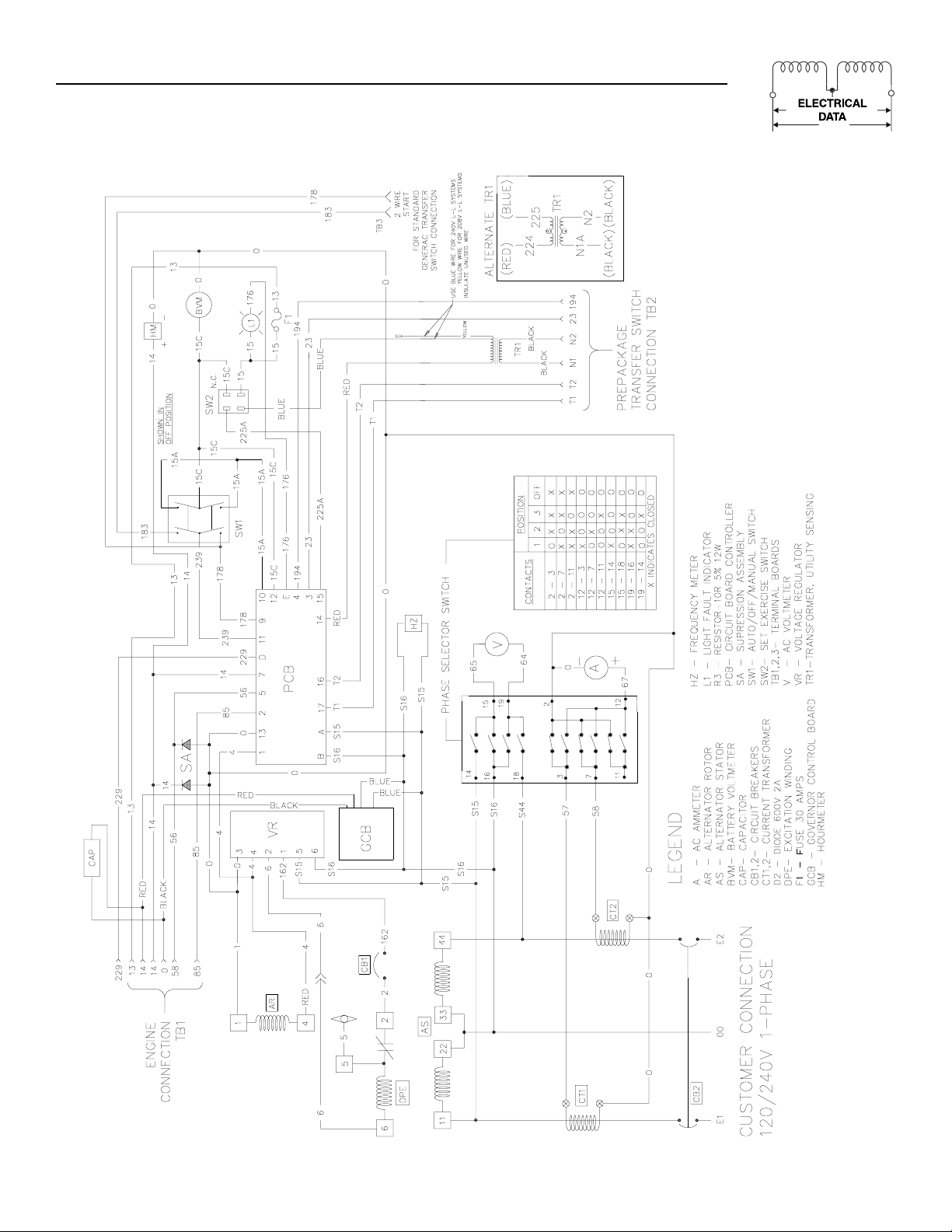
Wiring Diagram — Control Panel (1-Phase) —Drawing No. 0A2803C
FUSE
Page 23
Generac®Power Systems, Inc. 21
Section 6 - Electrical Data
Guardian Liquid-cooled 10 kW, 15 kW, 20 kW and 25 kW Generators
Electrical Schematic — Control Panel (1-Phase) — Drawing No. 0A2802A
Page 24
22 Generac®Power Systems, Inc.
Section 6 - Electrical Data
Guardian Liquid-cooled 10 kW, 15 kW, 20 kW and 25 kW Generators
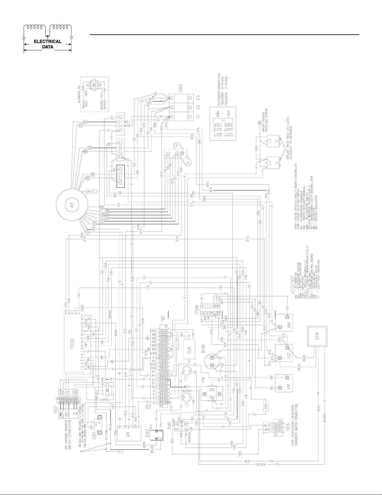
Wiring Diagram — Control Panel (3-Phase) — Drawing No. 0A2804C
Page 25
Generac®Power Systems, Inc. 23
Section 6 - Electrical Data
Guardian Liquid-cooled 10 kW, 15 kW, 20 kW and 25 kW Generators
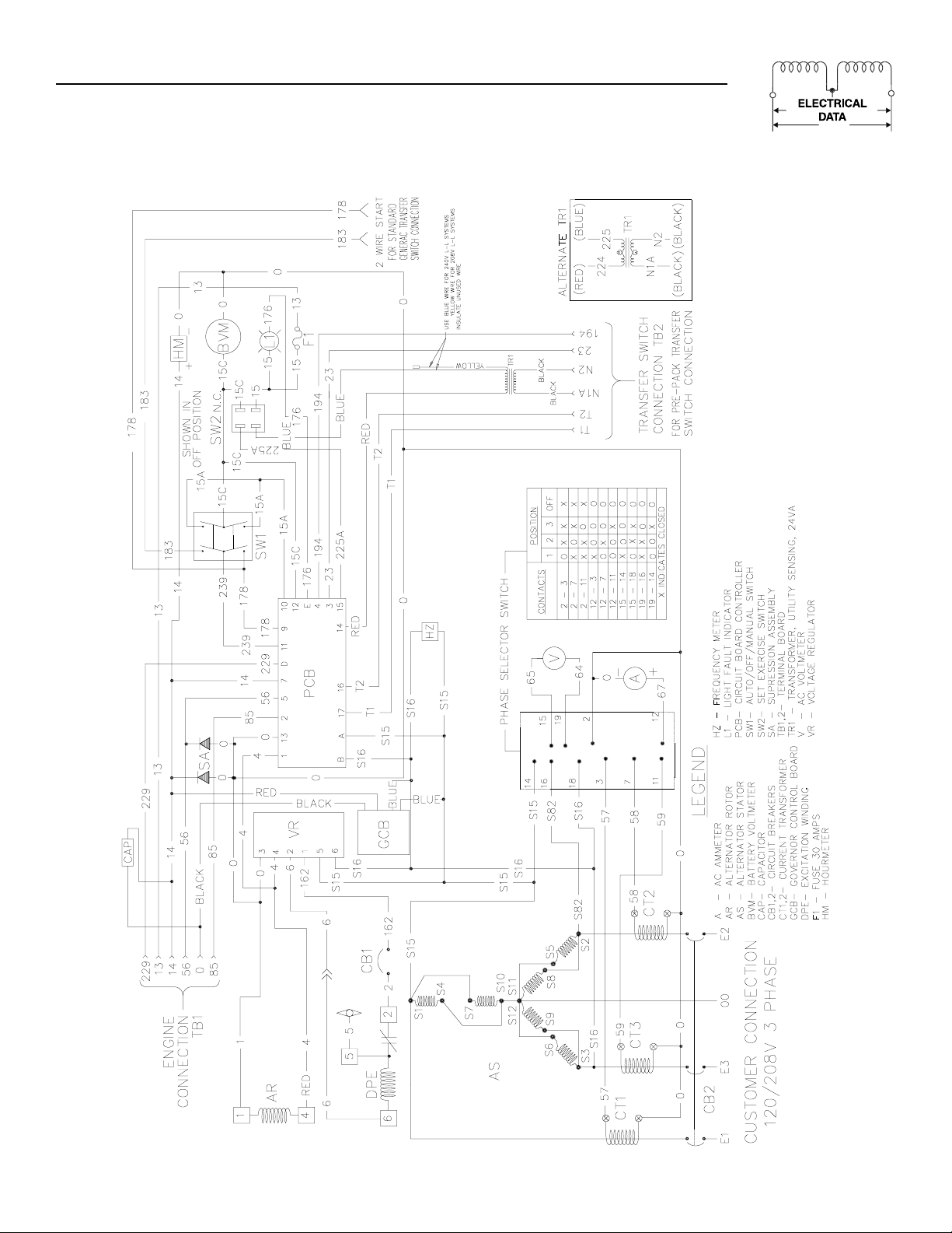
Electrical Schematic — Control Panel (3-Phase) — Drawing No. 0A2805B
Page 26

24 Generac®Power Systems, Inc.
Section 6 - Electrical Data
Guardian Liquid-cooled 10 kW, 15 kW, 20 kW and 25 kW Generators
Wiring Diagram — Control Panel (3-Phase) — Drawing No. 0A7176A
Page 27

Generac®Power Systems, Inc. 25
Section 6 - Electrical Data
Guardian Liquid-cooled 10 kW, 15 kW, 20 kW and 25 kW Generators
Electrical Schematic — Control Panel (3-Phase) — Drawing No. 0A7182A
Page 28

26 Generac®Power Systems, Inc.
Section 7 - Exploded Views and Parts
Guardian Liquid-cooled 10 kW, 15 kW, 20 kW and 25 kW Generators
Exploded View – Enclosure — Drawing No. 0C1404A
Page 29

Generac®Power Systems, Inc. 27
ITEM PART NO. QTY. DESCRIPTION
1 A2110 32 1/4"-20-1/2" FASTENER
2 A2115 32 1/4" NYLON WASHER
3 A3133A 4 SLIP HINGE, MALE L.H.
A3133B 4 SLIP HINGE, FEMALE L.H.
A3133C 2 SLIP HINGE, MALE R.H.
A3133D 2 SLIP HINGE, FEMALE R.H.
4 A3359 24 BHSCS M6 x 16 S.S.
5 A3360 24 SHAKEPROOF, INT M6 S.S.
6 C1245 1 PANEL, TOP SIDE L.H.
C1245A 1 PANEL,TOP SIDE R.H.
7 A3449 2 DOOR, SIDE
8 A4822 1 PANEL, FRONT
9 A4823 2 PANEL, SIDE BOTTOM
10 A4824 1 PANEL, REAR
11 A4825 1 CORNER POST, REAR L.H.
12 A4826 1 CORNER POST, REAR R.H.
13 C1193 1 TOP, ENCLOSURE
14 A4831 1 DOOR, REAR
15 A4832 2 DUCT
16 C1067 1 RADIATOR, SUPPORT-L.H.
17 C1067A 1 RADIATOR, SUPPORT-R.H.
18 C1068 1 SUPPORT, MUFFLER
19 C8817 1 TOP-CONTROL PANEL-SAE
20 C1244 1 FRONT AIR DUCT
21 A9955 1 BASE, MOUNTING
22 C1053Z 1 KIT, INSULATION 1.5L
23 22097 16 LOCKWASHER, 1/4"-M6
ITEM PART NO. QTY. DESCRIPTION
24 22129 12 LOCKWASHER, 5/16"-M8
25 22127 4 NUT, 1/2"-20
26 22145 12 FLAT WASHER, 5/16"-M8
27 89961 24ft. FOAM STRIP, 3/4" x 1/4"
28 22473 20 FLAT WASHER, 1/4"-M6
29 82570 1 PLUG BUTTON 4"
30 39253 12 HHCS, M8-1.25 x 20
31 42568 14 HHCS, M6-1.0 x 20LG
35 49813 4 NUT, HEX M6-1.0
37 37337 4 HEX NUT JAM-3/8"-24
38 A6807 1 LATCH & CAM (REWORK)
39 57042 2 LATCH AND CAM
40 67577 4 SPEED NUT 1/4"-20
42 22413 4 1/4"-20 x 1 HHCS
43 C1053B 1 INSULATION, PANEL TOP
44 C1053A 2 INSULATION, DOOR
45 C1053E 1 INSULATION, PANEL, FRONT R.H.
46 C1053F 1 INSULATION, PANEL, FRONT L.H.
47 C1063G 1 INSULATION, DUCT, FRONT
48 C1053H 1 INSULATION, PANEL, FRONT TOP
49 C1053D 2 INSULATION, PANEL, SIDE
50 C1053J 1 INSULATION, PANEL, REAR
51 C1053K 1 INSULATION, DUCT, L.H. SIDE
52 C1053L 1 INSULATION, DUCT, R.H. SIDE
53 C1053M 1 INSULATION, DOOR, REAR
54 78115 14 WASHER, SELF LOC/DOME
55 30486 2 RUBBER GROMMET
Section 7 - Exploded Views and Parts
Guardian Liquid-cooled 10 kW, 15 kW, 20 kW and 25 kW Generators
Exploded View – Enclosure — Drawing No. 0C1404A
Page 30

28 Generac®Power Systems, Inc.
Section 7 - Exploded Views and Parts
Guardian Liquid-cooled 10 kW, 15 kW, 20 kW and 25 kW Generators
Exploded View – Control Panel — Drawing No. 0C8847B
Page 31

ITEM PART NO. QTY. DESCRIPTION
1 0C5077 1 SUPPORT, CONTROL PANEL L.H.
2 075589 1 BRA CKET, VOLTAGE REGULATOR
3 0A1775 1 CONTRLPANEL-BACK
4 0C5078 1 SUPPORT CONTROL PANEL R.H.
5 0C4224A 1 SILKSCREEN, PANEL (SAE)
6 057073 1 BLOCK JUNCTION 3/8-16
7 022985 4 WASHER FLAT #6 ZINC
8 081988 1 DECAL EXERCISE INFO
9 070043 1 VOLTMETER AC 0-300
10 070055 1 AMMETER AC 0-100
11 070042 1 FREQUENCY METER 55-65HZ
12 070081 1 HOURMETER
13 076037 1 VOLTMETER DC 8-18V
14 022152 10 WASHER, LOCK #10
15 022158 10 NUT, HEX #10-32 STEEL
16 061945 1 SWITCH 6A AMP/V SELECTOR
17 032300 1 HOLDER, FUSE
18 022668 1 FUSE 30A X AGC30 HLDR22669 HKP
19 076020 1 SWITCH DPDT 15/10 SP ON-OFF-ON
20 083048 1 ASY POTTED REG WOFIN
21 0A2077 1 CIRCT BRK 125X2 120/240V
22 075476 14 SCREW, PPHM-M4-0.7 x 16MM
23 022264 14 WASHER, LOCK-M4
24 0A3968 1 CAPACITOR, FILTER ASSY.
25 039782 1 BRACKET CIRCT BRK MOUNTING
26 0C2323 2 SCREW TAPTITE PH 6-32X5/8 ZYC
27 076039 2 SCREW PPHM M5-0.8 X 40
28 051756 3 SCREW HHC M10-1.5 X 20 G8.8
29 048476 1 CIRCT BRK 4.5X1 AUT30KW CNT45K
30 022237 1 WASHER LOCK 3/8
31 022097 8 WASHER LOCK M6-1/4
32 022473 8 WASHER FLAT 1/4 ZINC
33 082573 1 SWITCH DPST 5 125V SPD RCKR
34 043116 4 SCREW HHC M6-1.0 X 12 G8.8
ITEM PART NO. QTY. DESCRIPTION
35 056739 1 RELAY SOLENOID 12VDC PNL MNT
36 072252 2 GROMMET 1.37 X .06 X 1.00
37 063212 1 GROMMET 1.75 X .12 X 1.50
38 058318 2 TRANSFRM 150A TO 5A 5VA
39 033121 2 SCREW HHM 10-32 X 1/2
40 049226 4 WASHER LOCK M5
41 023897 10 WASHER FLAT #10 ZINC
42 075595 1 ASSM.,CMA BOX
43 049811 8 WASHER FLAT M6
44 072355 2 HHCS M6-1X12-A/C-.HD
45 055440 1 SCREW HHC M5-0.8 X 25 G8.8
46 022241 1 NUT HEX 3/8-16 STEEL
48 022155 2 WASHER LOCK #6
49 098647 1 ASSY L.C. ELECT GOV
50 057335 1 BLOCK TERM 20A 20 X 6 X 1100V
51 021480 1 DECAL TERMINAL STRIP
52 048766 1 BLOCK TERM 20A 2 X 6 X 1100V
53 058589 1 DECAL WARN ENG START
54* 070882 1 ASSY SUPPRESSION
55 0A7215 10 SCREW SW 1/4-20X5/8 N WA JS500
56 076040 2 SCREW PPHM M5-0.8 X 16
57 049813 8 NUT HEX M6-1.0 G8 YEL CHR
58 061979 1 BUS BAR
59* 0A2833 1 HARNESS PNL "PP" 1P
60* 0A6821 1 HARNESS WIRING (1.5L)
61 064009 1 LIGHT 12VDC .02A LED RED PILOT
62 064009 1 DECAL, TRANS.SWITCH CONN.
63 0A1354A 1 REGULATOR - DC ALT
64 0C2212 6 SCREW TAPTITE PH M4-0.7X16 ZYC
65 0C3826 2 HINGE, CONTROL PANEL
66 0C4427 8 M6X1.0X12 T.H.M.S SS
67 0C8817 1 TOP, CONTROL PANEL (SAE)
*NOT SHOWN ON THIS ASSEMBLY
Section 7 - Exploded Views and Parts
Guardian Liquid-cooled 10 kW, 15 kW, 20 kW and 25 kW Generators
Exploded View – Control Panel — Drawing No. 0C8847B
Generac®Power Systems, Inc. 29
Page 32

30 Generac®Power Systems, Inc.
Section 7 - Exploded Views and Parts
Guardian Liquid-cooled 10 kW, 15 kW, 20 kW and 25 kW Generators
Exploded View – Radiator — Drawing No. 0C1406B
Page 33

Generac®Power Systems, Inc. 31
ITEM PART NO. QTY. DESCRIPTION
1 0A4822 1 PANEL FRONT
2 0A5734 1 RADIATOR 1.5L
3 0A6237 1 VENTURI 1.5L
4 0A6238 1 GUARD FAN
5 084918 1 HEATER 500W 1020
6 050967 12" HOSE RES 5/8 RIA 250F
7 057823 4 CLAMP HOSE #10 .56 - 1.06
8 099502 4 CLAMP HOSE #24 1.06 - 2.00
9 083709 2 CLAMP WIRE HOSE .573 - .551
11 042568 6 SCREW HHC M6-1.0 X 20 G8.8
12 022097 15 WASHER LOCK M6-1/4
13 049813 2 NUT HEX M6 -1.0 G8 YEL CHR
14 022473 11 WASHER FLAT M6-1/4 ZINC
15 084427 1 BRACKET HEATER
16 050967 18" HOSE RES 5/8 RIA 250F
17 075443 6 CRMPTIT 1/4-20 X 5/8
18 056892 4 CRMPTIT 10-24 X 3/8
19 0A6284 1 HOSE LOWER RADIATOR
20 0A6258 1 HOSE UPPER RADIATOR
21 029032 1 HOSE 9/32 ID
22 031669 4 BOLT CARR 1/4-20 X 1-3/4 JS500
23 060035 4 SPACER .41 X .75 X .87 ST/ZNC
24 022127 5 NUT HEX 1/4-20 STEEL
25 022145 12 WASHER FLAT 5/16 ZINC
26 022129 12 WASHER LOCK M8-5/16
27 045771 12 NUT HEX M8-1.25 G8 YEL CHR
28 042907 12 SCREW HHC M8-1.25 X 16 G8.8
29 076749 1 TANK COOLANT RECOVERY
30 080712 1 BRACKET COOLANT RECOVERY TANK
31 0A7215 1 SCREW SW 1/4-20X5/8 N WA JS500
32 030486 2 GROMMET 7/16 X 1/16 X 1/4
33 0A2111 2 SCREW SWAGE 10-32 X 5/16 Z/YC
34 065852 2 NUT SPRINGCLIP .37 - .62
35 0C1067A 1 SUPPORT RADIATOR RH
36 0C1067 1 SUPPORT RADIATOR LH
37 0C1480 1 BRACKET COOLANT BOTTLE
Section 7 - Exploded Views and Parts
Guardian Liquid-cooled 10 kW, 15 kW, 20 kW and 25 kW Generators
Exploded View – Radiator — Drawing No. 0C1406B
Page 34

ITEM PART NO. QTY. DESCRIPTION
1 0A9955 1 BASE MOUNTING
3 070936 2 DAMPENER VIBRATION
4 070936C 2 DAMPENER VIBRATION
5 039253 8 SCREW HHC M8-1.25 X 20 G8.8
6 022145 12 WASHER FLAT 5/16 ZINC
7 022129 12 WASHER LOCK M8-5/16
8 045771 12 NUT HEX M8-1.25 G8 YEL CHR
9 071956 4 WASHER FLAT M8
10 051730 2 SCREW HHC M8-1.25 X 60 G8.8
12 057821 2 SCREW HHC M8-1.25 X 40 G8.8
13 021991 1 EARTH STRAP
14 027482 2 WASHER SHAKEPROOF EXT 5/16 STL
15 0A2308 1 PLUG BUTTON 2" DIA
32 Generac®Power Systems, Inc.
Section 7 - Exploded Views and Parts
Guardian Liquid-cooled 10 kW, 15 kW, 20 kW and 25 kW Generators
Exploded View – Radiator — Drawing No. 0C1405A
Page 35

Generac®Power Systems, Inc. 33
ITEM PART NO. QTY. DESCRIPTION
1 0A4355 1 MANIFOLD EXHAUST 1.5L
2 0C1636 1 NIPPLE TOE 1.5 NPT X 6.5 BL IRON
3 036434 4 BOLT U 5/16-18 X 2.09
036449 4 SADDLE 2 INCH
4 0C1330 1 PIPE EXHAUST
5 0C1318 1 FLEX PIPE EXHAUST
6 0C1068 1 SUPPORT MUFFLER 1.5L
7 0C1412 1 ELBOW EXHAUST 45 DEG
8 0A5728 1 MUFFLER 1.6/1.5L SAE
9 060366 2 STRAP MUFFLER 6" DIA
10 066889 4 SCREW HHC M8 X 1.25 X 20MM
11 022145 4 WASHER FLAT 5/16 ZINC
12 022129 4 WASHER LOCK M8-5/16
13 045771 4 NUT HEX M8-1.25 G8 YEL CHR
14 0A8974 1 CAP RAIN 2"
Section 7 - Exploded Views and Parts
Guardian Liquid-cooled 10 kW, 15 kW, 20 kW and 25 kW Generators
Exploded View – Muffler — Drawing No. 0C1408B
Page 36
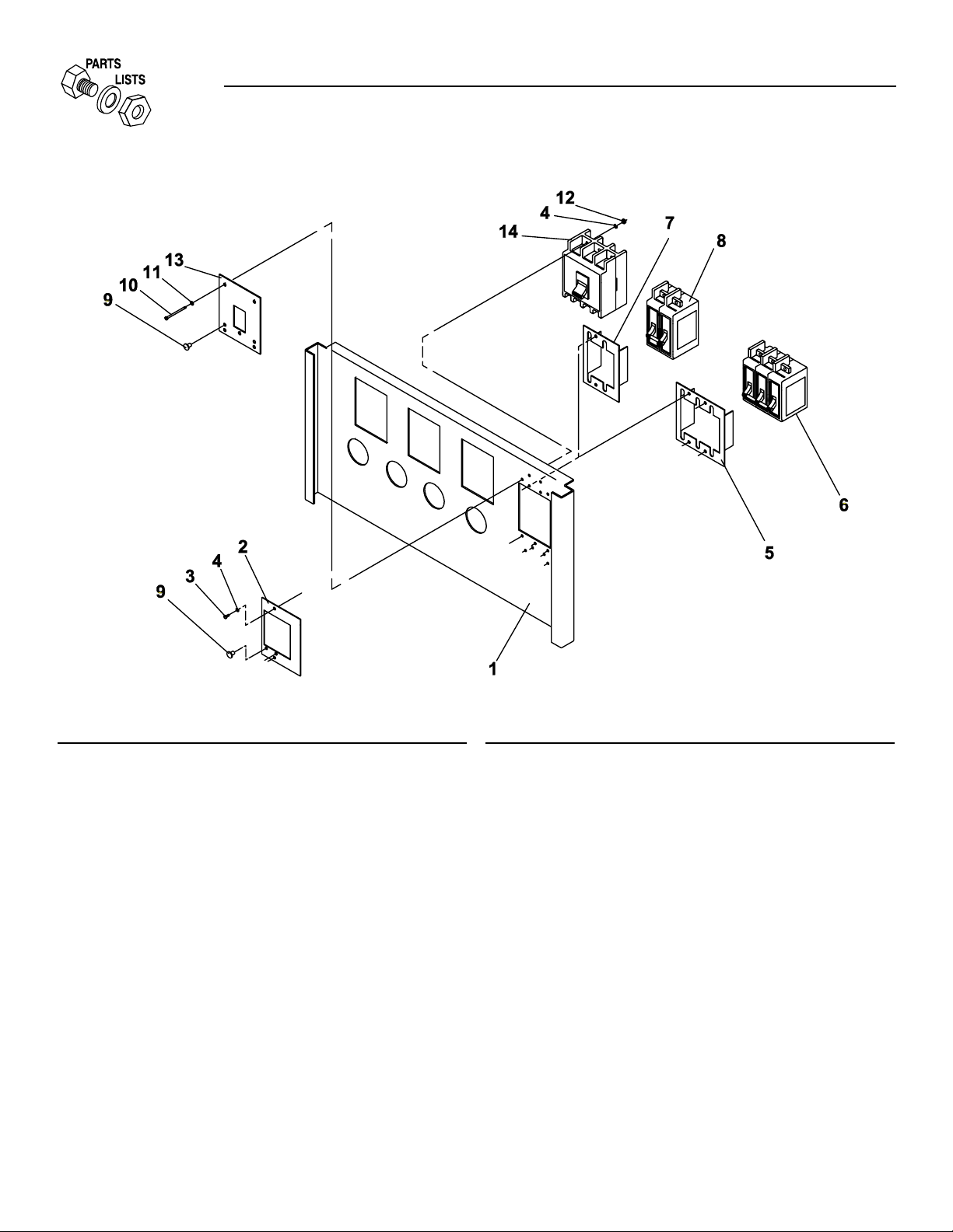
ITEM PART NO. QTY. DESCRIPTION
1 0A2103 1 SILKSCREEN "A" PANEL
0A2104 1 SILKSCREEN "B" PANEL
0A2105 1 SILKSCREEN "C" PANEL
0A2106 1 SILKSCREEN "P" PANEL
2* 0A2052 1 COVER BQ CIRCUIT BREAKER
3 033130 - SCREW HHM #8-32 X 1/4
4 022264 - WASHER LOCK M4
5 039783 1 BRACKET MOUNTING CIRCT BRK
6 080522 1 CIRCT BRK 20 X 3 INACTIVE
047585 1 CIRCT BRK 30 X 3 240V MT PL
057906 1 CIRCT BRK 35 X 3 240V
056783 1 CIRCT BRK 40X3 240V
049942 1 CIRCT BRK 50X3 W/MOUNT PL ITE
040533 1 CIRCT BRK 60X3 240V
049135 1 CIRCT BRK 70 X 3 240V
062812 1 CIR BKR 80-A 3P BQ3
053691 1 CIRCT BRK 90 X 3 ITE BQ3-B090
040532 1 CIRCT BRK 100X3 240V 39783 BR
7 039782 1 BRACKET MOUNTING CIRCT BRK
8 076640 1 CIRCT BRK 20 X 2 ITE BQ2-B020
057903 1 CIRCT BRK 25 X 2 240V ITE
057472 1 CIRCT BRK 30 X 2 240V ITE
077906 1 CIRCT BRK 35X2 W/39782 BRACKET
043240 1 CIRCT BRK 40X2 240V
ITEM PART NO. QTY. DESCRIPTION
057905 1 CIRCT BRK 45X2 240V
039765 1 CIRCT BRK 50X2 240V 39782 BRKT
048373 1 CIRCT BRK 70X2 240V
063452 1 CIRCT BRK 80X2 240V
039766 1 CIRCT BRK 90X2 240V
048374 1 CIRCT BRK 100X2 240V
0A2077 1 CIRCT BRK 125X2 120/240V
9 056967 3 PLUG PLASTIC .375
10 053640 4 SCREW RHM #8-32 X 3-1/4
11 038150 4 WASHER FLAT #8 ZINC
12 022471 4 NUT HEX #8-32 STEEL
13** 0A2670 1 COVER,CIR.BRKR. 480V
14 0A2820 1 MCB 16A 3P 480V B-TR
0A2821 1 MCB 25A 3P 480V B-TR
0A2822 1 MCB 32A 3P 480V B-TR
0A2828 1 MCB 40A 3P 480V B-TR
* USE WITH ITEM 14 ONLY
** USE WITH ITEM 8 ONLY
34 Generac®Power Systems, Inc.
Section 7 - Exploded Views and Parts
Guardian Liquid-cooled 10 kW, 15 kW, 20 kW and 25 kW Generators
Exploded View – Circuit Breaker — Drawing No. 0A3371B
Page 37
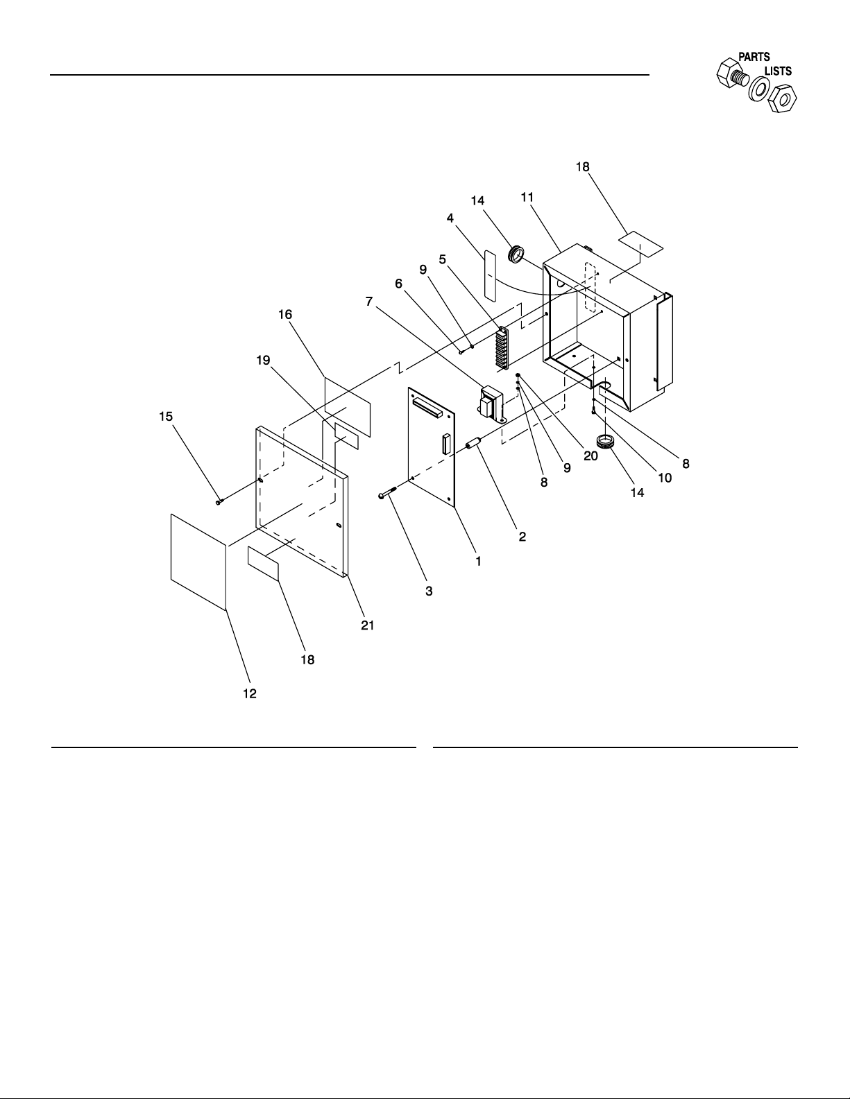
Generac®Power Systems, Inc. 35
ITEM PART NO. QTY. DESCRIPTION
1 074100 1 ASSY HOME STDBY LOGIC
(MODELS 921, 863, 865)
076009A 1 PP LOGIC ASM 50/60HZ
(MODEL 9428)
2 072566 4 NUT SPACER .250 PCB
3 080882 4 SCREW PPH TAPPING #6X5/8 SS
4 074978 1 DECAL TERMINAL STRIP
5 047822 1 BLOCK TERM 20A 7 X 6 X 1100V
6 075476 2 SCREW PPHM M4-0.7 X 16
7 083264 1 TRANSFORMER ASM CMA 240/12V
8 022985 4 WASHER FLAT #6 ZINC
9 022264 4 WASHER LOCK M4
10 051787 2 SCREW HHC M4-0.7 X 16 G8.8
11 079847 1 BOX CMA
12 0A8504 1 DECAL, CMA LABEL
0A8504A 1 DECAL, CMA LABEL
13* 022661V .083' TUBING SHRINK 19"ID RED
ITEM PART NO. QTY. DESCRIPTION
14 038057 2 GROMMET 7/8 X 1/16 X 3/4
15 058443 2 SCREW CRIMPTITE 1/4-20 X 5/8
16 081224 1 DECAL MFG NAMEPLATE
17* 079682 1 HARNESS CMA WIRE
18 086093 2 DECAL CMA WARNING
19 083736 1 DECAL CSA GTS
20 051715 2 NUT HEX M4-0.7 G8 YEL CHR
21 077401 1 COVER SILKSCREEN CMA
* NOT SHOWN
Section 7 - Exploded Views and Parts
Guardian Liquid-cooled 10 kW, 15 kW, 20 kW and 25 kW Generators
Exploded View – CMA Assembly — Drawing No. 081086D
Page 38
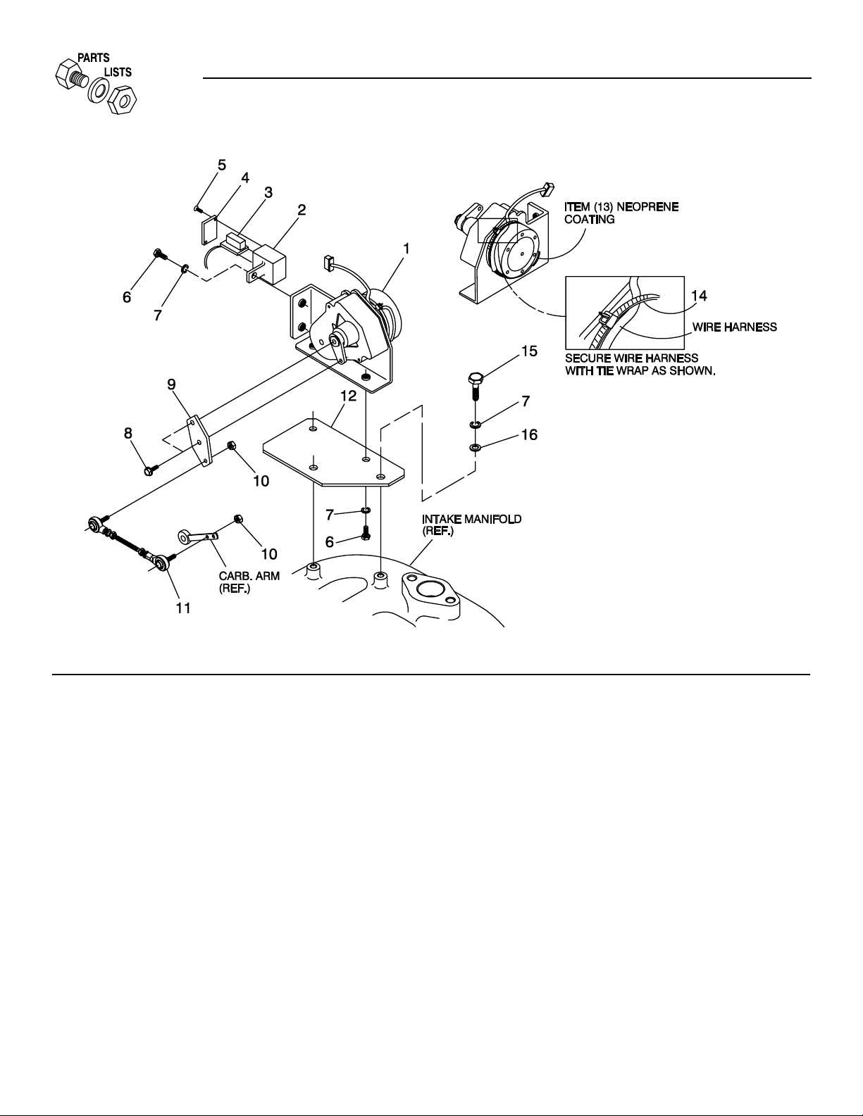
ITEM PART NO.QTY. DESCRIPTION
1 098290 1 ASM MOTOR STEPPER
2 098941A 1 HOUSING GOVERNOR CONNECTOR
3 098958A 1 CONNECTOR INTERFACE ASSEMBLY
4 098942A 1 COVER CONNECTOR HOUSING
5 098225 2 SCREW FHM #2 X 5/8 SELF TAP
6 043146 3 SCREW HHC M6-1.0 X 10 G8.8
7 022097 5 WASHER LOCK M6-1/4
8 064256 2 SCREW HHM #6-32 X 3/8 SELF TAP
9 098783 1 LEVER STEPPER MOTOR
10 037398 2 NUT LOCK HEX #10-32 NYL INS
11 0A7041 1 ASSEMBLY CARBURATOR LINKAGE
12 0A7106 1 BRACKET STEPPER MOTOR
13 074031 - LIQUID NEOPRENE
14 029333A 1 TIE WRAP 7" BLACK
15 022507 2 SCREW HHC 1/4-20 X 1/2 G5
16 022473 2 WASHER FLAT 1/4 ZINC
36 Generac®Power Systems, Inc.
Section 7 - Exploded Views and Parts
Guardian Liquid-cooled 10 kW, 15 kW, 20 kW and 25 kW Generators
Exploded View – Governor Assembly — Drawing No. 0A7216A
Page 39

Generac®Power Systems, Inc. 37
ITEM PART NO. QTY. DESCRIPTION
1 077483 1 BATT 12VDC 75-AH 26
2 038804D 1 CABLE BATT RED #4 X 20.00
3 038805B 1 CABLE BATT BLK #4 X 23.00
4 0742600131 1 ASSY,WIRE#16 RED 1.6
5 022131 1 WASHER FLAT 3/8 ZINC
6 046526 1 WASHER LOCK M10
7 052213 1 SCREW HHC M10-1.25 X 20 G8.8
8 059567 2 BOLT BATTERY HOLD DOWN
9 078121 1 BAR BATTERY HOLDDOWN
10 022145 2 WASHER FLAT M8-5/16 ZINC
11 022129 2 WASHER LOCK 5/16
12 022259 2 NUT HEX 5/16-18 STEEL
13 050331A 1 BATTERY POST COVER (RED+)
14 050331 1 BATTERY POSTCOVER (BLACK-)
15 075763 3 BOOT, BATTERY CABLE
Section 7 - Exploded Views and Parts
Guardian Liquid-cooled 10 kW, 15 kW, 20 kW and 25 kW Generators
Exploded View – Battery — Drawing No. 098922E
Page 40

38 Generac®Power Systems, Inc.
Section 7 - Exploded Views and Parts
Guardian Liquid-cooled 10 kW, 15 kW, 20 kW and 25 kW Generators
Exploded View – Generator — Drawing No. 0A9348B
Page 41

Generac®Power Systems, Inc. 39
ITEM PART NO. QTY. DESCRIPTION
1 098671 1 ASSY ROTOR 10KW
098681 1 ASSY ROTOR 15KW
098675 1 ASSY ROTOR 20KW
098936 1 ASSY ROTOR 25KW
2 0A5336A 1 HOUSING BLOWER
3 0A1659 1 SCREEN AIR OUTLET
4 071912 4 SCREW PPHM M5-0.8 X 8
5 022152 4 LOCK W ASHER-#10
6 051713 4 WASHER FLAT M5
7 022129 4 WASHER LOCK M8-5/16
8 098672 1 ASSY STATOR 10KW A
098673 1 ASSY STATOR 10KW D
098674 1 ASSY STATOR 10KW GJK
098682 1 ASSY STATOR 15KW 1PH A
098683 1 ASSY STATOR 15KW 3PH D
098684 1 ASSY STATOR 15KW 1PH GJK
098676 1 ASSY STATOR 20KW 1PH A
098677 1 ASSY STATOR 20KW 1PH A
098678 1 ASSY STATOR 20KW 1PH GJK
097620 1 ASSY STATOR 25KW 1PH A
098937 1 ASSY STATOR 25KW 1PH D
097621 1 ASSY STATOR 25KW 1PH D
9 0A5382 1 BEARING CARRIER REAR
10 075591 1 HOLDER, BRUSH ASSEM.
11 052813 4 SCREW HHC M4-0.7 X 20 G8.8
12 0A5601 1 COVER, REAR BEARING CARRIER
ITEM PART NO. QTY. DESCRIPTION
13 075554B 4 BOLT,STATOR X 16"LG
14 0A9375 4 SCREW RHM #10-24 X 2
15 022152 4 WASHER LOCK #10
16 097146 1 FAN & RING GEAR ASSEM.
17 042558 1 KEY SQ 3/8 X 1 STEEL
18 0A5061 1 SPACER-FLEX PLATE
19 0A4989 1 PLATE, FLEX
20 052213 1 SCREW HHC M10-1.25 X 20 G8.8
21 051769 6 WASHER LOCK M12
22 049541 4 SCREW HHC M10-1.5 X 35 G8.8
23 046526 4 WASHER LOCK M10
24 045772 4 NUT HEX M10-1.5 G8 YEL CHR
25** 082130B 1 ASSY MPU SPEED SENSOR 48"
26* 087599 1 PLUG PLASTIC 3/8 CAPLUG #2
27 077043E 1 FLEX CONDUIT 1" BLCK
(NOT SHOWN)
28 022131 4 WASHER FLAT 3/8 ZINC
29 072578 1 SPACER ROTOR SHAFT
30 0A7043 5 SCREW HHC M12-1.25 X 25 G8.8
31 049808 5 WASHER FLAT M12
32 058589 1 DECAL-WARNING
33 023365 4 WASHER SHAKEPROOF INT #8
35 0A8830 4 WASHER FLAT .34ID X .75OD
* USED ON PRE-PACKAGED UNITS ONLY
** USED ON "C" OPTION PANEL UNITS ONLY
Section 7 - Exploded Views and Parts
Guardian Liquid-cooled 10 kW, 15 kW, 20 kW and 25 kW Generators
Exploded View – Generator — Drawing No. 0A9348B
Page 42

40 Generac®Power Systems, Inc.
Section 7 - Exploded Views and Parts
Guardian Liquid-cooled 10 kW, 15 kW, 20 kW and 25 kW Generators
Exploded View – Natural Gas Fuel System — Drawing No. 0A9349E
Page 43

Generac®Power Systems, Inc. 41
ITEM PART NO. QTY. DESCRIPTION
1 0C2632 1 WELDMENT MOUNTING BASE
2 075580 2 FLANGE FUEL INLET
3 026915 3 NIPPLE CLOSE 3/4 X 1.375
4 039253 4 SCREW HHC-M8-1.25 X 20
5 022145 5 WASHER FLAT 5/16 ZINC
6 022129 7 WASHER LOCK M8-5/16
7 045771 4 NUT HEX M8-1.25 G8 YEL CHR
8 0A2666 2 SOLENOID GAS FUEL
9 046747 1 BUSHING REDUCER 3/4 TO 3/8
11 0C3714 1 ASSY HOSE NG/LPV.31"
13 0A5547 1 COVER AIR CLEANER
14 0C1475 1 REGULATOR NATURAL GAS EM
0A9911 1 REGULATOR L.P. GAS EM
15 0A7989 1 NIPPLE PIPE 3/8 NPT X 4 BLK IRON
16 0A6593 1 ADAPTOR CARBURETOR
17 059402 1 FILTER ELEMENT
18 037561 1 NUT WING 1/4-20 NYLK
19 059403 1 CARBURETOR, CA55 EM
20 059401 1 GASKET CARBURETOR
21 034154 4 SCREW PHM 10-24 X 1/2 CAD
22 022152 4 WASHER LOCK #10
23 023897 4 WASHER FLAT #10 ZINC
24 062522 1 STUD THR 1/4-20X3 F THR G2 ZNC
25 022127 1 NUT HEX 1/4-20 STEEL
26 022259 2 NUT HEX 5/16-18 STEEL
27 050280 1 DECAL FUEL INLET LPG
28 0A6125 2 STUD 5/16-18 X 1.25 F THR
29 052219 1 BARBED STR 1/8NPT X 5/16
30 048031C 3 CLAMP HOSE BAND 1/4
31 029032 6-1/2" HOSE 9/32 ID
32 029032 11" HOSE 9/32 ID
33 032552 1 BARBED EL 90 5/16 X 1/8NPT
34 0A4682 1 MANIFOLD INTAKE 1.5
35 042907 1 SCREW HHC M8-1.25 X 16 G8.8
36 055934D 1 CLAMP VINYL 1.06 X .406 Z
37 0A7040 1 BRACKET-RADIATOR HOSE
38 0C3153 1 TORX PLUS BHS M8 X 30
Section 7 - Exploded Views and Parts
Guardian Liquid-cooled 10 kW, 15 kW, 20 kW and 25 kW Generators
Exploded View – Natural Gas Fuel System — Drawing No. 0A9349E
Page 44

42 Generac®Power Systems, Inc.
Section 7 - Exploded Views and Parts
Guardian Liquid-cooled 10 kW, 15 kW, 20 kW and 25 kW Generators
Exploded View – Engine Compartment — Drawing No. 0A7642J
Page 45

Generac®Power Systems, Inc. 43
ITEM PART NO. QTY. DESCRIPTION
1 0A4531 1 ENGINE-1.5L
2 035685 1 CLAMP HOSE #28 1.32 - 2.25
3 075546A 1 PIPE-FLEX EXHAUST
4 0A45310258 1 GASKET-EXHAUST MANIFOLD
5 0A4355 1 MANIFOLD-EXHAUST
6 0A6699 1 SHIELD HEAT EXHAUST
7 022097 8 WASHER LOCK M6-1/4
8 022507 2 SCREW HHC 1/4-20 X 1/2 G5
9 052212 4 SCREW HHC M10-1.25 X 25 G8.8
10 046526 14 WASHER-LOCK-M10
11 022131 16 WASHER FLAT 3/8 ZINC
12 0C2499 2 STAMPING ENG FOOT
13 055993 1 SPACER .41 X .75 X .12 STL/ZNC
14 045772 4 NUT HEX M10-1.5 G8 YEL CHR
15 023586 2 SCREW SHC 5/16-18 X 2 G8.8 NZ
16 020692 1 STARTER-12V
17 0A7005 2 SPACER .56 X 1 X .37 ST/ZNC
18 052243 1 SCREW HHC M10-1.5 X 60 G8.8
19 0A4772 1 ENGINE PLATE
20 070901 2 SLEEVE DOWEL BLHSG
21 051735 3 SCREW HHC M10-1.5 X 70 G8.8
22 056768 2 SCREW HHC M10-1.5 X 90 G8.8
23 022145 2 WASHER FLAT 5/16 ZINC
24 022129 23 WASHER LOCK M8-5/16
25 022259 2 NUT HEX 5/16-18 STEEL
26 052213 1 SCREW HHC M10-1.25 X 20 G8.8
27 047411 2 SCREW HHC M6-1.0 X 16 G8.8
28 052830 2 SCREW HHC M10-1.25 X 45 G8.8
30 045771 10 NUT HEX M8-1.25 G8 YEL CHR
31 058306 5 SCREW SHC M8-1.25 X 25 G12.9
32 030795 2 SCREW HHC 5/16-18 X 1 G5
33 0A2711A 1 ADAPTER-THERMOSTAT
34 048665 1 GASKET THERMOSTAT
35 075885 1 THERMOSTAT 195 DEG
36 0A45310257 1 GASKET INLET MANIFOLD
37 0A4682 1 MANIFOLD-INTAKE
38 057522 1 SENSOR COOLANT LEVEL
39 0A6751 1 SW-TMP 245DEG 3/8NPT
ITEM PART NO. QTY. DESCRIPTION
40 034339 1 BARBED EL 90 3/8NPT X 5/8
41 026925 1 PLUG STD PIPE 3/8 STEEL SQ HD
42 061012 1 PLUG STD PIPE 1/8 SCKT HD
43 039253 6 SCREW HHC M8-1.25 X 20 G8.8
44 0A5110 1 PIPE WATER-INLET
45 0A7006 1 O-RING 1-1/16X1-5/16X1/8
46 025507 2 WASHER SHAKEPROOF EXT 7/16 STL
47 022500B 2 SPACER .41X.75X.25 ST/ZNC
48 0A8584 1 SWITCH OIL PRESSURE
49 036277 1 ELBOW 90D STREET 1/8
50 042574 1 ADAPTOR 1/8NPTF TO 1/8-28
51 026073A 1 PLUG STD PIPE 1/4 STEEL SQ HD
52 0A6701 1 SCREW HHC M10-1.5 X 110 G8.8
53 039414 1 SCREW HHC M8-1.25 X 35 G8.8
54 0A5568 1 SCREW HHC M12-1.25 X 55 G8.8
55 051769 1 WASHER LOCK M12
56 0A4804 1 PULLEY-CRANKSHAFT (1800 RPM)
0A4800 1 PULLEY-CRANKSHAFT (3600 RPM)
57 0A5839 1 BRACKET - ALT SUPPRT
58 0A1354B 1 DC ALTERNATOR-12V
59 0A4839 1 ARM ADJUST ALTERNATOR
60 055816 4 SCREW HHC M6-1.0 X 70 G8.8
61 049811 4 WASHER FLAT M6
62 075614 1 FAN ENG PUSHER 6/380
63 0A2628 1 PULLEY - FAN 95 DIA
64 0A5275 1 V-BELT 3/8 X 32-1/8 1.5L
0A5586 1 V-BELT 3/8 X 28.9 1.5L
65 0A4814 1 SPACER PULLEY
66 0A45310244 1 FILTER OIL
67 0C1852 1 ADAPTER DRAIN OIL
68 0912970066 1 GROUND WIRE (STARTER)
69 070928 1 CLAMP HOSE - OIL DRAIN
70 069860C 1 HOSE ASM.-OIL DRAIN
71 069811 1 CAP HEX 1/4NPT BRASS
72 0A5317 1 NAMEPLATE ENGINE
73 022473 2 WASHER FLAT 1/4 ZINC
Section 7 - Exploded Views and Parts
Guardian Liquid-cooled 10 kW, 15 kW, 20 kW and 25 kW Generators
Exploded View – Engine Compartment — Drawing No. 0A7642J
Page 46

44 Generac®Power Systems, Inc.
Section 8 — Installation
Guardian Liquid-cooled 10 kW, 15 kW, 20 kW and 25 kW Generators
Installation Drawing – Drawing No. 0C1450
Page 47

Generac®Power Systems, Inc. 45
Section 8 — Installation
Guardian Liquid-cooled 10 kW, 15 kW, 20 kW and 25 kW Generators
Installation Drawing – Drawing No. 0C1450
Page 48

46 Generac®Power Systems, Inc.
Section 9 — Notes
Guardian Liquid-cooled 10 kW, 15 kW, 20 kW and 25 kW Generators
Page 49

Generac®Power Systems, Inc. 47
Section 9 — Notes
Guardian Liquid-cooled 10 kW, 15 kW, 20 kW and 25 kW Generators
Page 50

48 Generac®Power Systems, Inc.
CALIFOR NIA EM ISSION CONTROL WARR ANT Y STATEM ENT
YOUR WARRANT Y R IGHTS AND OB LIGATIONS
The California Air Resources Board (CARB) and Generac Power Systems, Inc. (Generac) are pleased to explain the Emission
Control System Warranty on your new engine.* In California, new utility, and lawn and garden equipment engines must be
designed, built and equipped to meet the state’s stringent anti-smog standards. Generac will warrant the emission control
system on your engine for the periods of time listed below provided there has been no abuse, neglect, unapproved modification or improper maintenance of your engine.
Your emission control system may include parts such as the carburetor, ignition system and exhaust system. Generac will
repair your engine at no cost to you for diagnosis, replacement parts and labor, should a warrantable condition occur.
MANUFACTURER’S EMISSION CONTROL SYSTEM WARRANTY COVERAGE:
Emissions control systems on 1995 and later model year engines are warranted for two years as hereinafter noted. If, during such warranty period, any emission-related component or system on your engine is found to be defective in materials or
workmanship, repairs or replacement will be performed by a Generac Authorized Warranty Service Facility.
PURCHASER’S/OWNER’S WARRANTY R ESPONSIBILITIES:
As the engine purchaser/owner, you are responsible for the completion of all required maintenance as listed in your factory
supplied Owner’s Manual. For warranty purposes, Generac recommends that you retain all receipts covering maintenance
on your engine. However, Generac cannot deny warranty solely due to the lack of receipts or for your failure to ensure the
completion of all scheduled maintenance.
As the engine purchaser/owner, you should, however, be aware that Generac may deny any and/or all warranty coverage or
responsibility if your engine, or a part/component thereof, has failed due to abuse, neglect , improper maintenance or unapproved modifications, or the use of counterfeit and/or “grey market” parts not made, supplied or approved by Generac.
You are responsible for presenting your engine to a Generac Authorized Warranty Service Facility as soon as a problem occurs. The warranty repairs should be completed in a reasonable amount of time, not to exceed 30 days.
Warranty service can be arranged by contacting either your selling dealer or a Generac Authorized Warranty Service Facility.
To locate the Generac Authorized Warranty Service Facility nearest you, call our toll-free number:
1-800-333-1322
IMPORTANT NOTE: This warranty statement explains your rights and obligations under the Emission Control System
Warranty (ECS Warranty), which is provided to you by Generac pursuant to California law. See also the “Generac Limited
Warranties for Generac Power Systems, Inc.,” which is enclosed herewith on a separate sheet, also provided to you by
Generac. The ECS Warranty applies only to the emission control system of your new engine. If there is any conflict in terms
between the ECS Warranty and the Generac Warranty, the ECS Warranty shall apply except in circumstances where the
Generac Warranty may provide a longer warranty period. Both the ECS Warranty and the Generac Warranty describe important rights and obligations with respect to your new engine.
Warranty service can be performed only by a Generac Authorized Warranty Service Facility. When requesting warranty service, evidence must be presented showing the date of the sale to the original purchaser/owner.
If you have any questions regarding your warranty rights and responsibilities, you should contact Generac at the following address:
ATTENTION WARRANT Y DEPARTMENT
GENERAC POWER SYSTEMS, INC.
P.O. BOX 8
WAUKESHA, WI 53187
Part 1
Section 9 – Warranty
Guardian Liquid-cooled 10 kW, 15 kW, 20 kW and 25 kW Generators
Page 51

Generac®Power Systems, Inc. 49
EMISSION CONTROL SYSTEM WARRANTY
Emission Control System Warranty (ECS Warranty) for 1995 and later model year engines:
(a) Applicability: This warranty shall apply to 1995 and later model year engines. The ECS Warranty Period shall begin on
the date the new engine or equipment is purchased by/delivered to its original, end-use purchaser/owner and shall continue for 24 consecutive months thereafter.
(b) General Emissions Warranty Coverage: Generac warrants to the original, end-use purchaser/owner of the new engine or
equipment and to each subsequent purchaser/owner that each of its engines is ...
(1) Designed, built and equipped so as to conform with all applicable regulations adopted by the CARB pursuant to its
authority, and
(2) Free from defects in materials and workmanship which, at any time during the ECS Warranty Period, may cause a war-
ranted emissions-related part to fail to be identical in all material respects to the part as described in the engine manufacturer’s application for certification.
(c) The ECS Warranty only pertains to emissions-related parts on your engine, as follows:
(1) Any warranted, emissions-related parts that are not scheduled for replacement as required maintenance in the Owner’s
Manual shall be warranted for the ECS Warranty Period. If any such part fails during the ECS Warranty Period, it shall
be repaired or replaced by Generac according to Subsection (4) below. Any such part repaired or replaced under the
ECS Warranty shall be warranted for the remainder of the ECS Warranty Period.
(2) Any warranted, emissions-related part that is scheduled only for regular inspection as specified in the Owner’s Manual
shall be warranted for the ECS Warranty Period. A statement in such written instructions to the effect of “repair or
replace as necessary” shall not reduce the ECS Warranty Period. Any such part repaired or replaced under the ECS
Warranty shall be warranted for the remainder of the ECS Warranty Period.
(3) Any warranted, emissions-related part that is scheduled for replacement as required maintenance in the Owner’s
Manual shall be warranted for the period of time prior to the first scheduled replacement point for that part. If the part
fails prior to the first scheduled replacement, the part shall be repaired or replaced by Generac according to Subsection
(4) below. Any such emissions-related part repaired or replaced under the ECS Warranty shall be warranted for the
remainder of the ECS Warranty Period prior to the first scheduled replacement point for such emissions-related part.
(4) Repair or replacement of any warranted, emissions-related part under this ECS Warranty shall be performed at no
charge to the owner at a Generac Authorized Warranty Service Facility.
(5) When the engine is inspected by a Generac Authorized Warranty Service Facility, the owner shall not be held responsi-
ble for diagnostic costs if the repair is deemed warrantable.
(6) Generac shall be liable for damages to other original engine components or approved modifications proximately caused
by a failure under warranty of any emission-related part covered by the ECS Warranty.
(7) Throughout the ECS Warranty Period, Generac shall maintain a supply of warranted emission-related parts sufficient
to meet the expected demand for such emission-related parts.
(8) Any Generac authorized and approved emission-related replacement part may be used in the performance of any ECS
Warranty maintenance or repairs and will be provided without charge to the owner. Such use shall not reduce Generac
ECS Warranty obligations.
(9) Unapproved, add-on, modified, counterfeit and/or “grey market” parts may not be used to modify or repair a Generac
engine. Such use voids this ECS Warranty and shall be sufficient grounds for disallowing an ECS Warranty claim.
Generac shall not be held liable hereunder for failures of any warranted parts of a Generac engine caused by the use of
such an unapproved, add-on, modified, counterfeit and/or “grey market” part.
EMISSION RELATED PARTS INCLUDE THE FOLLOWING:
*Generac engine types covered by this warranty statement include the following:
1) Prepackaged Standby Generator
2) Auxiliary Power Unit (APU) Generator
3) Standby Generator
Part 2
Section 9 – Warranty
Guardian Liquid-cooled 10 kW, 15 kW, 20 kW and 25 kW Generators
1) Fuel Metering System:
1.2) LPG/Natural Gas carburetion assembly and its internal
components.
a) Fuel controller (if so equipped)
b) Mixer and its gaskets (if so equipped)
c) Carburetor and its gaskets (if so equipped)
d) Primary gas regulator (if so equipped)
e) LP liquid vaporizer (if so equipped)
2) Air Induction System including:
a) Intake pipe/manifold
b) Air cleaner
3) Ignition System including:
a) Spark plug
b) Ignition module
4) Catalytic Muffler Assembly (if so equipped) including:
a) Muffler gasket
b) Exhaust manifold
5) Crankcase Breather Assembly including:
a) Breather connection tube
Page 52

Part No. C8840 Revision 0 (04/25/01) Printed in U.S.A.
Section 9 – Warranty
Guardian Liquid-cooled 10 kW, 15 kW, 20 kW and 25 kW Generators
GENERAC’S STANDARD ONE-YEAR LIMITED WARRANTY FOR STANDBY POWER SYSTEMS
For a period of one year or 1,500 hours of operation from the date of original sale, whichever occurs first, Generac Power
Systems, Inc. (Generac) will, at its option, repair or replace any part which, upon examination by Generac or a
Generac/Guardian Authorized W arranty Service Facility, is found to be defective under normal use and service, in accordance
with the warranty schedule set forth below . Any equipment that the purchaser/owner claims to be defective must be returned
to and examined by the nearest Generac/Guardian Authorized Warranty Service Facility.
All transportation costs under the warranty, including return to the factory, are to be borne and prepaid by the
purchaser/owner. This warranty applies only to generators used in “Standby” applications, as Standby has been defined by
Generac, provided said generators have been initially installed and inspected on-site by a Generac/Guardian Authorized
Service Dealer or branch thereof.
WARRANTY SCHEDULE
YEAR ONE – 100 percent coverage on mileage*, labor and parts listed:
• Engine – All components
• Alternator – All components
• Transfer System – All components
*Travel allowance is limited to 300 miles or 7.5 hours, whichever occurs first, and applies only to permanently wired and
mounted units.
All warranty expense allowances are subject to the conditions defined in Generac’s Warranty Policies, Procedures and Flat
Rate Manual.
Units that have been resold are not covered under the Generac warranty, as this warranty is not transferable.
THIS WARRANTY SHALL NOT APPLY TO THE FOLLOWING:
1. Costs of normal maintenance, adjustments, installation and start-up.
2. Units sold, rated or used for “Prime Power” applications as Prime Power has been defined by Generac. Contact a distributor for Prime Power definition and warranty.
3. Failures due to (a) normal wear and tear, or (b) accident, misuse, abuse, negligence or improper installation.
4. Products that are modified or altered in a manner not authorized by Generac in writing.
5. Any incidental, consequential or indirect damages caused by defects in materials or workmanship, or any delay in repair
or replacement of the defective parts.
6. Failure due to misapplication.
7. Telephone, telegraph, teletype or other communication expenses.
8. Living or travel expenses of persons performing service, except as specifically included within the terms of a specific unit
warranty.
9. Rental equipment used while warranty repairs are being performed.
10. Overtime labor.
11. Starting batteries, fuses, light bulbs and engine fluids.
THIS WARRANTY IS IN PLA CE OF ALL OTHER WARRANTIES, EXPRESS OR IMPLIED. SPECIFICALL Y, GENERAC MAKES
NO OTHER WARRANTIES AS TO MERCHANTABILITY OR FITNESS FOR A PARTICULAR PURPOSE. Some states do not
allow limitations on how long an implied warranty lasts, so the above limitation may not apply to you.
GENERAC’S ONLY LIABILITY SHALL BE THE REPAIR OR REPLACEMENT OF PARTS AS STATED ABOVE. IN NO EVENT
SHALL GENERAC BE LIABLE FOR ANY INCIDENTAL OR CONSEQUENTIAL DAMAGES, EVEN IF SUCH DAMAGES ARE
A DIRECT RESULT OF GENERAC’S NEGLIGENCE. Some states do not allow the exclusion or limitation of incidental or
consequential damages, so the above limitation may not apply to you. Purchaser/owner agrees to make no claims against
Generac based on negligence.
This warranty gives you specific legal rights. You also may have other rights that vary from state to state.
GENERAC®POWER SYSTEMS, INC.
P.O. BOX 8
WAUKESHA, WI 53187
 Loading...