

Page 1
POWER SYSTEMS, INC
Owner’s Manual
• Model: 000595-1 and 009843-3
PRIMEPACT 70G and 70LP
Air-cooled Recreational
Vehicle Generators
Page 2

INTRODUCTION
♦ READ THIS MANUAL THOROUGHLY________________
If you do not understand any portion of this manual,
contact Generac or your nearest Generac Authorized
Service Dealer for starling, operating and servicing
procedures.
'rhroughoLit this publication, and on tags and
decals affixed to the generator, DANGER, WARNING.
CAUTION and NOTE blocks arc used to alert you to
special instruction about a particular operation that
may be hazardous if performed incorrectly or care
lessly. Observe them carefully. Their definitions are
as follows:
DANGER
After this heading, you can read instructions that,
if not strictly complied with, will result in personal
injury or property damage.
-------
M. WARNING
After this heading, you can read instructions that,
if not strictly complied with, may result in person
al injury or property damage.
-------
M. CAUTION
After this heading, you can read instructions that,
if not strictly complied with, could result in dam
age to equipment and/or property.
NOTE:
After this heading, you can read explanatory
statements that require special emphasis.
These safety warnings cannot eliminate the hazards
that they indicate. Common sense and strict compli
ance with the sirecial instructions while performing
the service are essential to preventing accidents.
lanir commonly used safety symbols accompany the
Danger, Warning aiid Caution blocks. The type of
information eacli indicates follows:
This symbol points out important safety infor
A
mation that, if not followed, could endanger
personal safety and/or property of you and
others.
This symbol points out potential explosion
hazard.
This symbol points out potential fire hazard.
A-
-------------------
-------------------
A
^ This symbol points out potential electrical
shock hazard.
The operator (driver) is responsible for proper and
safe use of the vehicle and its equipment, and the
safety of all vehicle occupants. We strongly recom
mend that the operator read this manual and thor
oughly understand all instructions before using this
equipment. We also strongly recommend instructing
other occupants in the vehicle to properly start and
operate the generator. This prepares them if they
need to operate the equipment in an emergency.
♦ CONTENTS
This manual contains pertinent owner’s information,
including warranty, electrical diagrams, exploded
views and lists of repair parts for generator model
numbers 000595-1 and 009843-3. In addition, the
latter portion of this manual contains information
necessary for the proper installation of these
generators.
♦ OPERATION AND MAINTENANCE
It is the operator's responsibility to perform all safe
ty checks, to make sure that all maintenance for safe
operation is performed promptly and to have the
equipment checked periodically by a Generac
Authorized Service Dealer. Normal maintenance ser
vice and replacement of parts are the responsibility of
the owner/operator and, as such, are not considered
defects in materials or workmanship within the
terms of the warranty Individual operating habits
and usage contribute to the need for maintenance
service.
Proper maintenance and care of your generator
ensure a minimum number of problems and keep
operating expenses at a minimum. See your Generac
Authorized Service Dealer for service aids and acces
sories.
♦ HOW TO OBTAIN SERVICE
When your generator requires servicing or repairs,
simply contact a Generac Authorized Service Dealer
for assistance. Service technicians are factory-trained
and are capable of handling all of your service needs.
When contacting a Generac Authorized Service
Dealer or the factory about parts and service, always
supply the complete model number and serial num
ber of your unit as given on its data decal, which is
located on your generator.
Model No. Serial No.
_________________________________
_________________
_____________________
AUTHORIZED SERVICE
DEALER LOCATION
To locale the GENERAC AUTHORIZED SERVICE
DEALER nearest you, please call tills number:
Generac* Power Systems, Inc.
1-800-333-1322
ONLY DEALER LOCATION INFORMATION
CAN BE OBTAINED AT THIS NUMBER.
Locate us on the web at:
www.generac.com
Page 3

Table of Contents
PRIMEPACT 70G and 70LP Recreational Vehicle Generators
Part I — Operating Instructions
Introduction..................................Inside Front Cover
Read This Manual Thoroughly ..........................................................IFC
Contents..............................................................................................IFC
Operation and Maintenance ...............................................................IFC
How to Obtain Service
Autliorized Service Dealer Locator Number
Safety Rules
......................................................
......................................................................
.....................................
IFC
It'C
2
Section 1 - General Information..............................4
1.1 Generator Identification ................................................................4
1.2 Generator Applicability
1.3 Installation .................................................................................... 5
1.4 Safety ............................................................................................5
1.5 Generator AC Connection System.................................................5
1.6 Specifications ................................................................................6
1.6.1 Fuel Requirements & Consumption
1.6.2 Engine Oil Requirements
1.6.3 Generator Specifications
1.6.4 Engine Specifications
1.6.5 Emissions Compliance Period ..........................................7
.................................................................
.................................
.................................................
...................................................
.......................................................
Section 2 - Operation...........................................7
2.1 Generator Control Panel..................................................................7
2.1.1 Fuel Primer........................................................................ 7
2.1.2 Star:. Slop Switcli .............................................................7
2.1.3 15 Amp Fuse.....................................................................7
2.1.4 Line Breakers.....................................................................7
2.2 Optional Remote Start/Stop Panel
2.3 Automatic Choke
2.3.1 Choke Solenoid .................................................................8
2.3.2 Prechoke............................................................................8
2.4 Before Starting the Engine ............................................................8
2.4.1 Installation
2.4.2 Engine Lubrication
2.4.3 Fuel Supply .......................................................................8
2.4.4 Cooling and Ventilating Air
2.4.5 Engine Exhaust Gas ..........................................................9
2.5 Starting the Generator ...................................................................9
2.6 Stopping the Generator.................................................................. 9
2.7 Applying Loads to Generator ........................................................9
2.7.1 Letting the Engine Stabilize
2.7.2 Do Not Overload the Generator ......................................10
2.8 Protection Systems.......................................................................10
2.8.1 Low Oil Pressure Switch.................................................10
2.8.2 High Temperature Switch................................................10
2.8.3 Field Boost.......................................................................10
2.8.4 Overvoltage Protection ....................................................II
2.8.5 25-Hour Break-in Period
2.8.6 25-Hour Checkup............................................................11
2.8.7 Operation in High Grass or Brush ..................................11
Section 3 - Maintenance
3.1 Checking the Engine Oil Level.....................................................11
3.2 Changing the Engine Oil and/or Oil Filter...................................12
3.3 Maintaining the Engine Air Cleaner ...........................................12
3.3.1 Cleaning the Foam Precleaner.........................................12
3.4 Clean Air Intake Screen ..............................................................13
3.5 Checking the Engine Spark Plug
3.6 Fuel Filter (Gasoline Only] .........................................................13
3.7 Spark Arrestor Muffler
3.8 Cleaning the Generator................................................................ 14
3.9 Battery Maintenance....................................................................14
3.9.1 Weekly ............................................................................14
3.9.2 Every Six Months ...........................................................14
3.10 Major Service Manual
3.11 Drive Belt ....................................................................................15
3.12 Exercising the Generator
3.13 Out of Service Procedure ............................................................15
3.13.1 Removal From Service
3.13.2 Return to Service
3.14 Wattage Reference Guide
..........................................................................
.........................................................................
.....................................
................................................................
.................................................................
.................................................
...........................................................
.............................................
.............................................
................................................
.................................................
............................................................
................................................
.........................................................
............................................................
11
—11
13
13
15
15
15
15
15
Section 4 - Notes...............................................16
Part II - Installation Instructions
Safety Rules
..................................................
Section 5 — General Information
5.1 Purpose and Scope of the Manual..........................................20
5.2 Safely ...........................................................................................70
5.3 Standard Booklets ........................................................................20
5.4 Eciuipment Description
5.5 Generator Engine Operating Speed..............................................20
5.6 Generator AC Connection System
Major Dimensions and F'eatures
5
6
6
6
7
8
8
8
8
8
9
Section 6 — Installation......................................22
6.1 Location and Sup]«)ii
6.1.1 Generator Locati(3ii
6.1.2 Generator Supports .........................................................22
6.1.3 Suspended Mounting
6.1.4 Generator Restraint .........................................................23
6.2 Generator Compartments
6.2.1 Comi)artmenl Size .........................................................23
6.2.2 Conqiartmenl Construction .............................................23
6.2.3 Sound Insulating Materials
6.2.4 Acoustics .........................................................................24
6.2.5 Compaiiinent Floor Cutouts
6.3 Cooling and Ventihition............................................................... 26
6.3.1 Generator Airflow............................................................26
6.3.2 Cooling Air Inlet Openings .............................................26
6.3.3 Compensating for Restrictions ........................................27
6.3.4 Testing the Installation ....................................................27
6.4 Gasoline luiel System ..................................................................27
6.4.1 Fuel'Rutk .........................................................................28
6.4.2 Generator Fuel Supply Line ............................................28
6.4.2.1 Rigid Fuel Lines
6.4.2.2 Flexible Fuel Lines
6.5 LP Gas Fuel System ....................................................................28
6.5.1 Parts not included in Fuel System ..................................28
6.5.2 Some Important Considerations.......................................29
6.5.3 Vapor Withdrawal
6.5.4 Primary Regulator............................................................29
6.5.5 Gaseous Carburetion .......................................................29
6.5.6 Fuel Supply Lines............................................................30
6.5.7 Excess Flow Valve
6.5.8 Leakage 'lests...................................................................30
6.6 Exhaust Systems...........................................................................30
6.6.1 Mufflers and Spark Arrestors..........................................31
6.6.2 lYpe of Exhaust System
6.6.3 Exhaust System Safety
6.7 Electrical Connections ................................................................31
6.7.1 Electrical Junction Box
6.7.2 Wiring.............................................................................. 32
6.7.3 Generator AC Connections .............................................32
6.7.4 Conduit.............................................................................32
6.7.5 Isolating Different Power Sources...................................32
6.7.6 Power Supply Cord..........................................................33
6.7.7 Ground Fault Circuit Interrupters
6.8 Battery Installation ......................................................................34
6.8.1 Ftecomrnended Battery ...................................................34
6.8.2 Battery Cables .................................................................34
6.8.3 Battery Cable Connections
6.8.4 Battery Compartment
6.9 Optional Accessories.................................................................... 34
6.9.1 Remote Panel Models
...............................................................
..................................................................
Section 7 — Post Installation
7.1 Post Installation Tests
7.2 Before Initial Start-up
7.3 Initial Start....................................................................................35
7.4 Testing Under Load......................................................................35
7.5 Installation Checklist ...................................................................36
....................................................................
..................................................................
Section 8 - Troubleshooting
8.1 Troubleshooting Guide
..................................................................
.............................
18-19
..........................
..........................................
.................................................
........................................................
......................................................
.............................................................
..............................................
...........................................
.....................................................
.................................................
...........................................................
..........................................................
.................................................
....................................................
..................................................
...................................
............................................
......................................................
....................................................
...............................
.................................
17
20
20
20
21
22
22
22
23
24
2.5
28
28
29
30
31
31
31
33
1.14
34
35
35
35
35
37
37
Section 9 - Electrical Data....................................39
Section 10 - Exploded Views and Parts Lists
.............
40
Section 11 - Notes.............................................51
Section 12 - Warranty ........................................52
Generac® Power Syetems, Inc.
Page 4

SAFETY RULES
operation be copied and posted in potential hazard areas of the recreational vehicle. Vk
Safety should be stressed to all operators and potential operators of this equipment.
A
Safety Rules
PRIMEPACT 70G and 70LP Recreational Vehicle Generators
SAVE THESE INSTRUCTIONS - The manufacturer suggests that these rules for safe
Ma\
The engine exhaust from this product
contains chemicals known to the state
defects or other reproductive harm.
■ 1
I
This product contains or emits chemicals
I
known to the state of California to cause
I
cancer, birth defects or other reproductive harm.
Study these SAFETY RULES carefully before
installing, operating or servicing this equipment.
Become familiar with this manual and with the unit.
The generator can operate safely, efficiently and reli
ably only if it is properly installed, operated and
maintained. Many accidents are caused by failing to
follow simple and fundamental rules or precautions.
Generac cannot possibly anticipate every possible
circumstance that might involve a hazard. The warn
ings in this manual, and on tags and decals
affixed to the unit, are, therefore, not all-inclusive. If
yon use a procedure, work method or operating tech
nique Generac does not specifically recommend, you
must satisfy yourself that it is safe for you and others.
You also must make sure the procedure, work
method or operaiing technique that you choose does
not render the generator unsafe.
Despite the safe design of this generator,
operating this equipment imprudently, neglect
ing its maintenance or being careless can cause
possible injury or death. Permit only responsi
ble and capable persons to operate or maintain
this equipment.
Potentially lethal voltages are generated by
A
these machines. Ensure all steps are taken to
render the machine safe before attempting to
work on the generator.
Parts of the generator are rotating and/or hot
during operation. Exercise care near running
generators.
WARNING:
of California to cause cancer, birth
WARNING: □
DANGER
^ GENERAL HAZARDS ^
For safety reasons, Generac recommends
that the installation, initial start-up and mainte
nance of this equipment is carried out by a
Generac Authorized Service Dealer.
The engine exhaust fumes contain carbon monox
ide. which can be DEADLY. This dangerous gas, if
breathed in sufficient concentrations, can cause
unconsciousness or even death. This exhaust sys
tem must be installed properly, in strict compli
ance with applicable codes and standards.
Following installation, you must do nothing that
might render the system unsafe or in noncompli
ance with such codes and standards. The genera
tor compartment must be completely vapor sealed
from the vehicle interior. There must be no possi
bility of exhaust fumes entering the vehicle interi
or. Never operate this equipment with a leaking or
defective exhaust system.
Keep hands, feet, clothing, etc., away from drive
belts, fans, and other moving or hot parts. Never
remove any drive belt or fan guard while the unit is
operating.
Adequate, unobstructed flow of cooling and venti
lating air is critical to correct generator operation
and is required to expel toxic fumes and fuel
vapors from the generator compartment. Without
sufficient cooling airflow, the engine/generator
quickly overheats, which causes serious damage to
the generator. Do not alter the installation or per
mit even partial blockage of ventilation provisions,
as this can seriously affect safe operation of the
generator.
When working on this equipment, remain alert at
all times. Never work on the equipment when you
are physically or mentally fatigued.
Inspect the generator regularly, and contact your
nearest Generac Authorized Service Dealer imme
diately for parts needing repair or replacement.
Before performing any maintenance on the genera
tor, disconnect its battery cables to prevent acci
dental start up. Disconnect the cable from the bat
tery post indicated by a NEGATIVE, NEG or (-)
first. Reconnect that cable last.
Never use the generator or any of its parts as a
step. Stepping on the unit can stress and break
parts, and may result in dangerous operating con
ditions from leaking exhaust gases, fuel leakage,
oil leakage, etc.
Generac' Power Systems, Pnc.
Page 5

Safety Rules
PRiMEPACT 70G and 70LP Recreational Vehicle Generators
SAFETY RULES
A
ELECTRICAL HAZARDS
• The generator covered by this manual produces
dangerous electrical voltages and can cause fatal
electrical shock. Avoid contact with bare wires, ter
minals, connections, etc., while the unit is running.
Ensure all appropriate covers, guards and barriers
are in place before operafing the generator. If you
must work around an operating unit, stand on an
insulated, dry surface to reduce shock hazard.
• Do not handle any kind of elecfrical device while
standing in water, while barefoot, or while hands
or feet are wet. DANGEROUS ELECTRICAL
SHOCK MAY RESULT.
• During installation onto the vehicle, have the gen
erator properly grounded (bonded) either by solid
mounting to the vehicle frame or chassis, or by
means of an approved bonding conductor. DO
NOT disconnect the bonding conductor, if so
equipped. DO NOT reconnect the bonding conduc
tor to any generator part that might be removed or
disassembled during routine maintenance. If the
grounding conductor must be replaced, use only a
flexible conductor that is of No. 8 American Wire
Gauge (AWG) copper wire minimum.
• In case of accident caused by electric shock, imme
diately shut down the source of electrical power. If
this is not possible, attempt to free the victim from
the live conductor. AVOID DIRECT CONTACT
WITH THE VICTIM. Use a nonconducting imple
ment, such as a rope or board, to free the victim
from the live conductor. If the victim is uncon
scious, apply first aid and get immediate medical
help.
• Never wear Jewelry when working on this equip
ment. Jewelry can conduct electricity resulting in
electric shock, or may get caught in moving com
ponents causing injury.
A
FIRE HAZARDS
For fire safety, the generator must be installed and
maintained properly. Installation always must
comply with applicable codes, standards, laws and
regulations. Adhere strictly to local, slate and
national electrical and building codes. Comjdy
with regulations the Occupational Safety and
Health Administration (OSHA) has establislu'd.
Also, ensure that the generator is installed in
accordance with the manufacturer’s instructions
and recommendations. Following proper installa
tion, do nothing that might alter a safe installation
and render the unit in noncompliance with the
aforementioned codes, standards, laws and regu
lations.
Keep a fire extinguislicr in the vehi('le at all times.
Extinguishers rated “ABC’’ by the National Fire
Protection Association are appropriate for use on
the recreational vehicle generator elei’lrical sys
tem. Keep the extinguisher properly charged and
be familiar with its use. If you have any question
pertaining to fire extinguishers, consult your local
fire department.
A
EXPLOSION HAZARDS
Do not snroke around the generator. Wi]re rqr any
fuel or oil spills immediately. Ensure that no com
bustible materials arc left in the generator com
partment, or on or near the generator, as FIRE or
EXPLOSION may result. Keep the area surround
ing the generator clean and free from debris.
Gasoline is extremely FLAMMABLE and its vapors
are EXPLOSIVE, Do not permit smoking, open
flame, sparks or any source of heat in the vicinity
while handling gasoline. Comply with all laws gov
erning the storage and handling of gasoline.
This generator may use liquid propane (LP) gas as
a fuel. LP gas is highly EXPLOSIVE. The gas is
heavier than air and tends to settle in low areas
where even the slightest spark can ignite the gas
and cause an explosion.
A
Generac* Power Systems, Inc.
Page 6
GENERAL
INFORMATION
Section 1 - General Information
PRIMEPACT 70G and 70LP Recreational Vehicle Generators
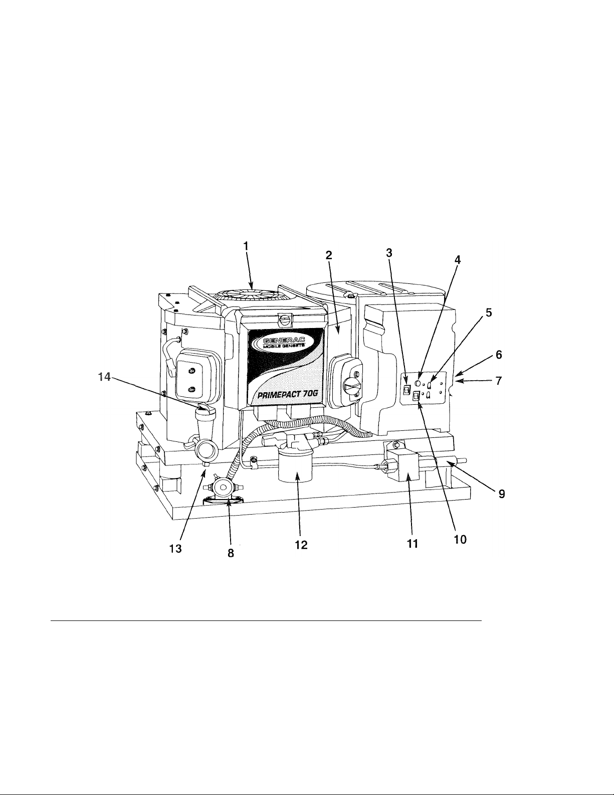
1.1 GENERATOR IDENTIFICATION
Please record the following information from the generator DATA DECAL or information decal.
1. Model Number____________________ 2. Serial Number
3. kW Rating
5. Phase___________________________6. Hertz ______________________________
_______________________
4. Rated Voltage
______________________
_______________________
REFERENCE NUMBER IDENTIFICATION
1. Generator Air Intake Screen
8. Starter Contactor
2. Data Plate 9. Fuel Inlet
3. Enirine Start/Stop Switch 10. Fuel Primer Switch
4. 15 amp Fuse 11. Fuel Pump
5. 30 amp Circuit Breaker
6. Optional Remote Panel Receptacle
12. Oil Filter
13. Oil Drain Plug
7. Generator AC Output Leads 14. Oil Dipstick and Filler Tube
Generac* Power Systems, Inc.
Page 7

Section 1 - General Information
PRiMEPACT 70G and 70LP Recreational Vehicle Generators
GENERAL
INFORMATION
1.2 GENERATOR APPLICABILITY
These generators have been designed and manufac
tured for supplying electrical power for recreational
vehicles. You should not modify the generator or use
it for any application other than for what it was
designed. If there are any questions pertaining to its
application, write or call the factory. Do not use the
unit until you have been advised by competent
authority.
DANGER
For fire safety, the generator must have been
A
properly installed in compliance with ANSI
119.2-1975/NFPA 501C-1974, "Standard for
Recreational Vehicles, Part III - Installation of
Electrical Systems." The generator also must
have been installed in strict compliance with
the manufacturer's detailed installation instruc
tions. After installation, do nothing that might
render the unit in noncompliance with such
codes, standards and instructions.
You can use your generator set to supply electrical
power for operating one of the following electrical
loads:
• PRIMEPACT 70G: 120 and/or 240 volts, single
phase, 60 Hz electrical loads. These loads can
require up to 7000 watts (7.0 kW) of power, but
cannot exceed 58.3 AC amperes of current at 120
volts or exceed 29.2 AC amperes at 240 volts.
• PRIMEPACT 70LP: 120 and/or 240 volts, single
phase, 60 Hz electrical loads. These loads can
require up to 6600 watts (6.6 kW) of power, but
cannot exceed 55 AC amperes of current at 120
volts or exceed 27.5 AC amperes at 240 volts.
-------
M. CAUTION M
Do not overload the generator. Some installa
tions may require that electrical loads be alter
nated to avoid overloading. Applying exces
sively high electrical loads may damage the
generator and may shorten its life. Add up the
rated watts of all electrical lighting, appliance,
tool and motor loads the generator will power
at one time. This total should not be greater
than the wattage capacity of the generator. If
an electrical device nameplate gives only volts
and amps, multiply volts times amps to obtain
watts (volts X amps = watts). Some electric
motors require more watts of power (or amps
of current) for starting than for continuous
operation.
-----------------
1.3 INSTALLATION
This Owner's Manual has been prepared under (he
assumption that a competent, qualified technician
installed the generator into an induslrial vehicle. We
also assume the installer complied with all apirlicable
codes, standards and regulations pertaining to instal
lation.
An INSTALLATION MANUAL was sliipped witli llie
generator. That Manual contains inanufactnrer's
instructions and recommendations for installing the
unit into an industrial vehicle. After installation,
installers should forward the Installation Manual to
Owners/Operators for their information.
Owners/Operators have the responsibility to make
sure that nothing is done that might render the instal
lation unsafe or in non-complianc(' with apirlicable
codes, standards and instructions.
1.4 SAFETY
Before using the generator set, carefully read GEN
ERAL SAFETY RULES inside the cover. Comply with
these RULES to prevent accidents and damage to
equipment and/or property. Generac suggests copy
ing and posting the GENERAL SAFE'l'Y RULES to
potential operators of this equipment.
1.5 GENERATOR AC CONNECTION
SYSTEM
These air-cooled generator sets are equipped with
dual stator AC power windings. These two stator
windings supply electrical power to customer electri
cal loads by means of a dual 2-wire connection sys
tem.
Generators may be installed to provide the following
outputs;
1) 120 VAC loads only — one load with a mirxiinum
total wattage requirement equal to the generator’s
rated power output (in watts), and 120V across the
generator output terminals.
2) 120/240 VAC loads — one load with a niiiximum
total wattage requirement equal to the generator’s
rated power output, and 240 V across the generator
output terminals; or two seperate loads, each willi a
maximum total wattage requirement equal to half of
the generator’s rated power output (in watts), and
120 V across the generator output terminals.
Generac* Power Systems, inc.
Page 8
GENERAL
INFORMATION
Section 1 - General Information
PRIMEPACT 70G and 70LP Recreational Vehicle Generators
Figure 1.1 - Connection for 120 Volts Only
Figure 1.2 - Connection for 120/240 Volts
1.6 SPECIFICATIONS
♦ 1.6.1 FUEL REQUIREMENTS
'I'llis <>('ncralor is equijiped with a gasoline fuel system
as standard e(|uipinent. Specific installations may pro
vide either a separate fuel tank for the generator, or the
generator may ''share’' the veliicle engine's fuel tank.
Fuel Consumption (gph/ibs.ph)
Model
PrimePact 70G
PrimePact 70LP
No Load 1/2 Load
0.34 0.65
0.47/2.01
0.85/3.62 1.66/7.05
Full Load
1.12
NOTE
Some installations using a “shared” fuel tank may
have a generator fuel pickup tube that is shorter
than the vehicle engine’s pickup tube. Such an
arrangement causes the generator engine to “run
out of gas” while adequate fuel for the vehicle
remains in the tank.
To reduce lead and carbon deposits use high quality
UNLEADED gasoline with the generator. Leaded
REGULAR grade gasoline is an acceptable substitute.
NOTE:
Using unleaded gasoline contributes to longer engine
valve life by reducing lead and carbon deposits.
-A CAUTION A-
Generac does not recommend using any
A
gasoline containing alcohol (such as "gasohol").
If you use any gasoline containing alcohol, it
must not contain more than 10 percent ethanol,
and it must be removed from the generator
during storage. Do NOT use any gasoline
containing methanol. If you use gasoline with
alcohol, inspect more frequently for fuel leaks
and other abnormalities.
♦ 1.6.2 ENGINE OIL REQUIREMENTS
________________
Use only high quality detergent oil classified “For
Service SF” and with an oil viscosity rating of SAE
lOW-30 oil. Do not pour in any additives to the rec
ommended oil. Engine crankcase capacity is 1.4
liters. See Section 3.2 on page 11 for oil level check
and filing procedures.
♦ 1.6.3 GENERATOR SPECIFICATIONS
SERIES
Rotor RPM
Rotor Poles
Engine RPM
Rated Max. Continuous AC Output*
Voltage*
Rated Max. Continuous Current* 58.3 AC ampsf
Phase
Frequency
Battery Charging Current (Max.)
Weight
Length
Width
Height 15.75 inches 15.75 inches
■ All units are reconnectable to 120 and’or 240 volts, dual voltage output. Units are not listed per RVIA'ANSI when reconnected for dual voltage output
f Rated maximum continuous current at 240 volts is 29,2 amps,
N Rated maximum continuous current at 240 volts is 27.5 amps.
B Generac^ Power Systems, Inc.
PRIMEPACT 70G PRIMEPACT 70LP
3600 3600
2
2900 2900
7000 waits (7.0 kW) 6600 watts (6,6 kW)
120 120
1 1
60 Hertz 60 Hertz
10 amps (regulated) 10 amps (regulated)
221 pounds 224 pounds
25 inches 25,75 inches
18.5 inches 18.5 inches
2
55.0 AC amps N
Page 9
Section 2 - Operation
PRIMEPACT 70G and 70LP Recreational Vehicle Generators
♦ 1.6.4 ENGINE SPECIFICATIONS
_________________
'lype of Engine
PRIMEPACT 70G/70LP
Cooling Metliod
....................................................
...........................................
Air-coolcd
GNG80
Rated Horsepower
PRIMEPACT 70G/70LP .....................................16 at 3600
Displacement
PRIMEPACT 70G/70LP
............................................
480cc
Compression Ratio.......................................................8.6 to 1
Cylinder Block .........................Aluminum w/Cast Iron Sleeve
Type of Governor
............................
Mechanical, Fixed Speed
Engine Governor Speed...........................................2900 rpni
Air Cleaner
.......................
Paper Element w/Foam Pi'ecleaner
Starter ........................................................12-volt DC Electric
Ignition System
.....................
Solid-state w/Flywheel Magneto
Recommended Spark Plug
Champion
..............................................................
RC12YC
AC................................................................................R45S
Fram AutoUte ..................................................................65
Spark Plug Gap
Recommended Min. Battery
♦ 1.6.5 EMISSIONS COMPLIANCE PERIOD
.......................................
...........
400 Cold Cranking Amps
0.030 inch (0.8 mm)
* •
For nonhandled engines the Emissions Compliance
Period referred to on the Emissions Compliance
Label indicates the number of operating hours for
which the engine has been shown to meet Federal
emission requirements.
• For engines less than 225 cc displacement,
Category C=125 hours, B = 250 hours, and A=500
hours.
• For engines of 225 cc or more. Category C = 250
hours, B = 500 hours, and A= 1000 hours.
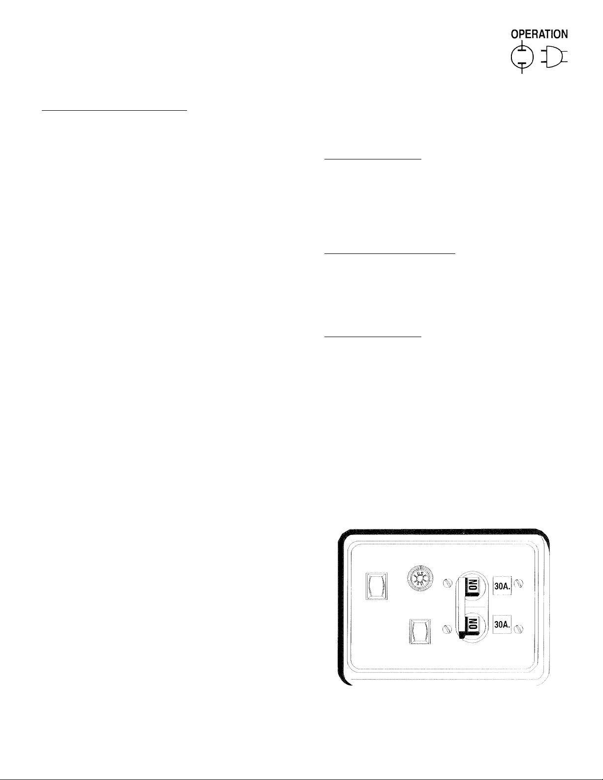
2.1 GENERATOR CONTROL PANEL
The following features are mouiiied on the generator
control panel (Figure 2,1):
♦ 2.1.1 FUEL PRIMER
Before starting a cold engine (if it has not been start
ed in more than two weeks), you must press this
switch for approximately ten seconds to bring fuel
from the tank to the fuel pump. This rocker ty[3C
switch springs back into its original ¡rosition when
you release it.
♦ 2.1.2 START/STOP SWITCH
To crank and start the engine, hold this switch in the
START position. Release the .switcli when the engine
starts. To stop an operating engine, press and hold
the switch in the STOP position until the engine shuts
off. The switch center position is the ItlJN position.
♦ 2.1.5 15 AMP FUSE
The fuse protects the engine's DC control circaill
against electrical overload. If the fuse element has
melted open due to overloading, the engine cannot be
cranked. If you must replace the fuse, use only an
identical 15 amp replacement fuse.
♦ 2.1.4 LINE BREAKERS
Protects generator’s AC output circiut against
overload, i.e., prevents unit from exceeding
wattage/amperage capacity. This unit has two iiO-ang:)
breakers.
Figure 2.1 - Typical Control Panel
START T5A BREAKER
__________________________
____________________
__________________________
FUSE IVIAIIM
STOP FUEL
PRilVlER
Generac* Power Systems, Inc.
~7
Page 10

OPERATION
Section 2 - Operation
PRIMEPACT 70C and 70LP Recreational Vehicle Generators
NOTE:
If this generator has been reconnected for dual
voltage AC output (120/240 volts), you can install
line breakers having an amperage rating that is
different than that stated above. The replacement
line breakers consist of two separate breakers with
a connecting piece between the breaker handles
(so that both breakers will operate at the same
time). If the unit is reconnected for dual voltage,
it is no longer RVIA listed.
2.2 OPTIONAL REMOTE
START/STOP PANEL
A remote mounted Start/Stop Panel (Figure 2.2) is
available that allows you to start and stop the gener
ator engine conveniently from inside the vehicle. The
remote panel includes a Start/Stop switch,
hour meter, generator run lamp and a wire harness.
Figure 2.2 — Optional Remote Panel
(Models 004057 and 004184)
♦ 2.3.2 PRECHOKE
The choke system also has a temperature-sensitive
metal strip that adjusts choke valve angle according
to ambient temperatures (i.e., in cold ambient tem
peratures, choke valve closes more). Once the engine
starts, an element heats the temperature-sensitive
strip to a normal operating condition, opening the
choke valve. This may take about three minutes in
cooler weather.
2.4 BEFORE STARTING THE ENGINE
NOTE:
Instructions and information in this manual
assume the generator has been properly installed,
connected, serviced, tested and adjusted by a
qualified installation technician or installation
contractor.
♦ 2.4.1 INSTALLATION___________________________
Generator installation must have been properly com
pleted so it complies with all applicable codes, stan
dards and regulations and with the manufacturer's
recommendations.
_
____
_
(For drawing, see Instruction Sheet P/N A9579)
' 1 J ^l T q]
.
....,.......
-
2.3 AUTOMATIC CHOKE
This engine is equipped with an automatic choke that
consists of two main components: a choke solenoid
and irrechoke.
♦ 2.5.1 CHOKE SOLENOID
During engine cranking (Start/Stop switch at
START), a solid-state choke module signals the
choke solenoid to activate and cycle (choke on/chokc
off) until the engine starts. The choke solenoid thus
opens and closes the carburetor choke valve only
when the engine is cranking. When (he engine starts,
(he choke sto[3S cycling.
________________________
♦ 2.4.2 ENGINE LUBRICATION
Have the engine crankcase properly serviced with the
recommended oil before starting. Refer to Section
1.6.3 (Page 6) and Sections 3.1 and 3.2 (Page 11) for
oil servicing procedures and recommendations.
-------
M. CAUTION ik
Any attempt to crank or start the engine before
A
you have properly serviced it with the recom
mended oil may result in an engine failure.
♦ 2.4.3 FUEL SUPPLY____________________________
The engine must have an adequate supply of proper
fuel to operate. Before starting it, check that sufficient
fuel is available.
Depending on the installation, the generator may
have either a separate fuel tank, or it may “share”
the vehicle engine’s fuel tank.
♦ 2.4.4 COOLING AND VENTILATING AIR
Air inlet and outlet openings in the generator com
partment must be open and unobstructed for contin
ued proper operation. Without sufficient cooling and
ventilating airflow, the engine/generator quickly over
heats. which causes it to shut down and may damage
the generator.
-----------------
NOTE:
Generac' Power Systems, Inc.
Page 11

PRIMEPACT 70G and 70LP Recreational Vehicle Generators
♦ 2.4.5 ENGINE EXHAUST GAS_____________________
Before starting the generator engine, you should be
sure there is no way for exhaust gases to enter tlie
vehicle interior and endanger people or animals.
Close windows, doors and other openings in the vehi
cle that, if open, might permit exhaust gases to enter
the vehicle.
DANGER
The generator engine gives off DEADLY carbon
monoxide gas through its exhaust system. This
dangerous gas, if breathed in sufficient concen
trations, can cause unconsciousness or even
death. Never operate the generator set with
the vehicle inside any garage or other enclosed
area. DO NOT OPERATE THE GENERATOR IF THE
EXHAUST SYSTEM IS LEAKING OR HAS BEEN
DAMAGED. SYMPTOMS OF CARBON MONOX
IDE POISONING ARE (a) inability to think coher
ently; (b) vomiting; (c) twitching muscles; (d)
throbbing temples; (e) dizziness; (f) headaches;
(g) weakness; and (h) sleepiness. IF YOU FEEL
ANY OF THESE SYMPTOMS, MOVE INTO FRESH
AIR IMMEDIATELY. IF SYMPTOMS PERSIST, GET
MEDICAL HELP.
2.5
Read the vehicle manufacturer’s instructions. The
owner/operator should become familiar with the
vehicle in which this generator is installed.
Differences exist between vehicles. For example,
some vehicles may use a transfer switch to isolate
dockside power from the generator, while other
vehicles may use an isolating receptacle. Some
vehicles may be equipped with a DC converter
which allows the generator to power certain DC
lighting and other DC loads.
To crank and start the generator engine, proceed as
follows:
1. Turn OFF electrical loads using the means pro
If starting from the generator control panel, turn
OFF loads by setting the generator’s main circuit
breaker to the OFF (or open) position. If starting
from a remote panel, turn OFF loads using the
means provided in the vehicle (such as a main cir
cuit breaker). Electrical load circuits will be
turned ON after the generator has started, stabi
lized and warmed up.
STARTING THE GENERATOR
NOTE:
vided in your vehicle (such as a main line circuit
breaker or transfer switch).
NOTE:
Section 2 - Operation
2.
If you have not started the engine in more than
two weeks, press the Fuel Pump Primer switch
and hold it for about 10 seconds. However, if the
engine is warm, skip Step 2.
3.
To crank and start the engine, hold the start/stop
switch at START. Release the switch when the
engine starts.
-------
Mk CAUTION
If the engine does not start after it has been
^ cranking for 15 seconds, release the Start/Stop
switch and wait 1 minute before trying again.
Holding the switch for longer than 15 seconds
can damage the starter motor.
4.
Let the engine run at no-load for a few minutes to
stabilize and warm up.
5.
Turn ON electrical loads using the means
provided (such as a main circuit bicaker oitransfer switch).
---------------
OPERATION
2.6 STOPPING THE GENERATOR
1. Turn OFF all electrical loads using the means
provided (such as a main circuit breaker or
transfer switch).
Let generator run at no-load for a few minutes, to
2.
stabilize internal engine generator temperatures.
Place the Start/Stop switch in its STOP position.
3.
The engine will come to a complete stop.
2.7 APPLYING LOADS TO GENERATOR
When applying electrical loads to the generator,
observe these guidelines:
• Before applying electrical loads, let the generator
stabilize and warm up for a minute or two.
“ DO NOT overload the generator.
♦ 2.7.1 LETTING THE ENGINE STABILIZE
The generator supplies correct rated voltage only at
the proper governed speed. Some electrical appli
ances may be extremely sensitive to voltage. Incorrect
voltages can damage such appliances.
If electrical loads are applied at reduced operating
speeds, such loads imposed on the engine when suf
ficient power is not available may shorten engine life.
Never turn ON electrical loads until after the genera
tor engine has started and stabilized at no-load.
Generac* Power Systems, Inc.
Page 12
OPERATION
Section 2 - Operation
PRIMEPACT 70G and 70LP Recreational Vehicle Generators
• 2.7.2 DO NOT OVERLOAD THE GENERATOR
You can read the rat- ’ waltage/amperage capacity of
your generator on the generator data decal (see
Section 1.1 on Page 4).
Applying electrical loads in excess of the unit’s rated
capacity will cause the engine/generator to automati
cally shut down.
To avoid overloading, add up the wattage of all con
nected electrical lighting, appliance, tool and motor
loads. This total should not be greater than the gen
erator’s rated wattage capacity.
• Most lighting, appliance, tool and motor loads indi
cate their required watts on their nameplate or
data plate. For light bulbs, simply note the wattage
rating of the bulb.
• If a load does not show its rated wattage, multiply
that load’s rated VOLTS times AMPS to obtain
WATTS.
• Induction type motors (such as those that run the
vehicle’s furnace fan, refrigerator, air conditioner,
etc.) need about 2-1/2 times more watts of power
for starting than for running (for a few seconds
during motor starling). Be sure to allow for this
when connecting electrical loads to the generator.
First, figure the watts needed to start electric
motors in the system. To that figure, add the run
ning wattages of other items lliat will be operated
by the generator.
• Do not apply heavy electrical loads for the first two
or three hours of operation.
2.8 PROTECTION SYSTEfVIS
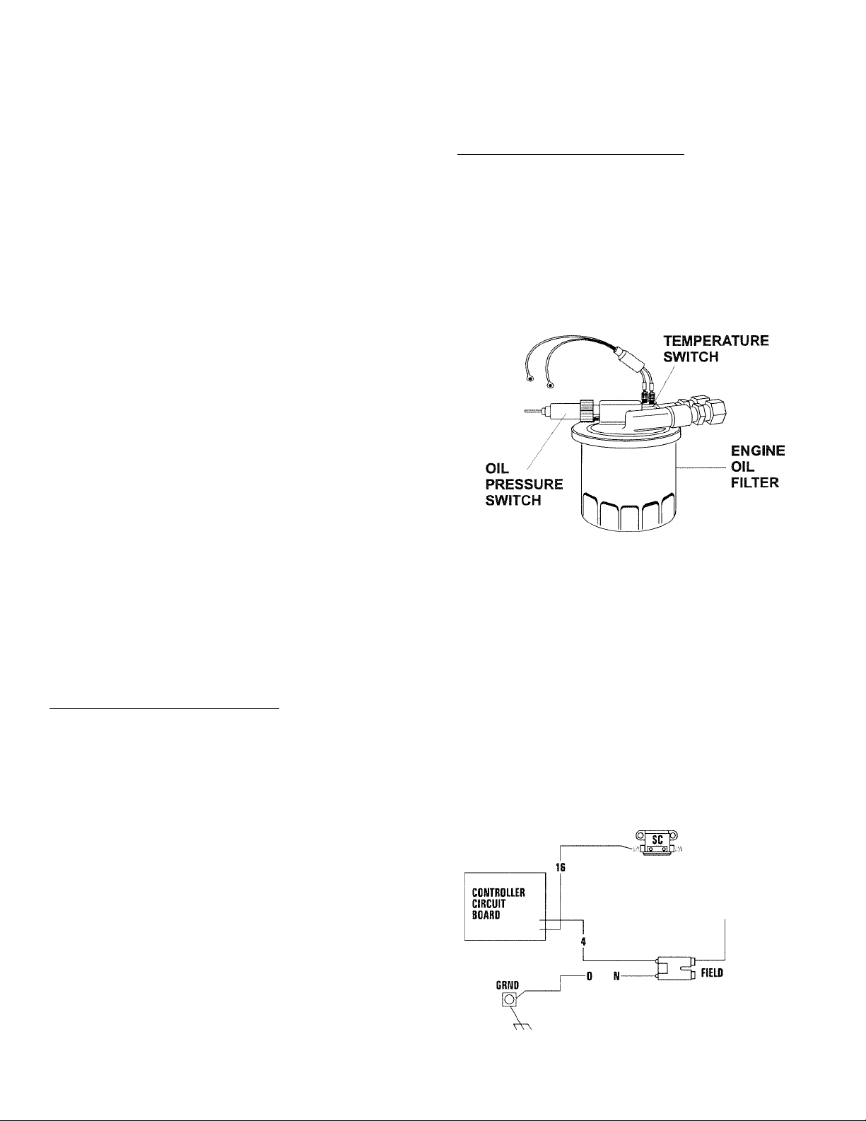
• 2.8.1 LOW OIL PRESSURE SWITCH
I'his switch (Figure 2.3 on page 10) has normally
closed (N.C.) contacts that arc held open by engine oil
l)i essure during cranking and operating. Should oil
j^ressure drop below a ¡preset level, switch contacts
close, and the engine automatically shuts down. The
unit should not be restarted until oil is added.
_______________
♦ 2.8.2 HIGH TEMPERATURE SWITCH
_______________
This switch (Figure 2.3), which has normally open
(N.O.) contacts, is mounted near the oil filter. The
contacts close if the temperature should exceed
approximately 284° F (140° C), initiating an engine
shutdown.
Figure 2.3 - Low Oil Pressure and
High Temperature Switches
HIGH
♦ 2.8.3 FIELD BOOST
The Controller Circuit Board houses a field boost
diode and resistor that are not part of the automatic
choke circuit. These two components are part of a
“field boost” circuit (Figure 2.4). During engine
cranking only, a positive DC (battery) voltage is deliv
ered through the diode, resistor, brushes and slip
rings, and the generator rotor. Application of this
voltage to the rotor “flashes the field” whenever it is
started. Flashing of the field each time the generator
starts makes sure that a sufficiently strong magnetic
field is available to produce “pickup” voltage in the
stator windings.
Figure 2.4 - Field Boost Circuit
1 O Generac’ Power Systems, Inc.
CLOSEST TO
BEARING
Page 13
Section 3 - Maintenance
PRIMEPACT 70C and 70LP Recreational Vehicle Generators
MAINTENANCE
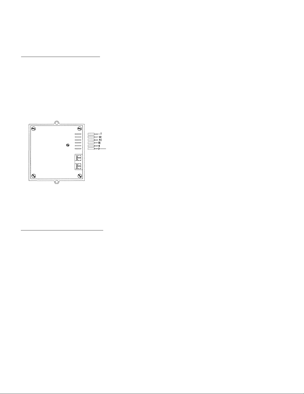
♦ 2.8.4 OVERVOLTAGE PROTECTION________________
A solid-state voltage regulator (Figure 2.5) controls
the generator’s AC output voltage. This regulator sup
plies an excitation current to the rotor. By regulating
the rotor’s excitation current, the strength of its mag
netic field is regulated and, in turn, the voltage deliv
ered to connected electrical loads is controlled. When
the AC frequency is 50 Hertz, voltage is regulated at
115 volts.
Figure 2.5 - Solid State Voltage Regulator
'yy-SENSING
+)t_to rotor
)—T(DIRECT CURRENT)
----
hEROM STATOR
EXCITATION WINDING
(ALTERNATING CURRENT)
The voltage regulator also incorporates a “voltage
surge protection circuit.” This circuit prevents trou
blesome surges in the generator AC output voltage.
Voltage surge is a common cause of damage to elec
tronic equipment.
• 2.8.5 25-HOUR BREAK-IN PERIOD
_____________
The first 25 hours of operation is the break-in period
for the generator. Properly breaking in the generator
is essential to minimize fuel consumption and pro
vide maximum engine performance. During this 25-
hour break-in period, follow this procedure:
• Run the unit at varying electrical loads to help seat
the engine piston rings properly.
• Check the engine oil level frequently. Add oil if
needed. It is normal for the generator engine to
consume more oil than is normal until the piston
rings have properly seated.
• For the 75-hour operation following the break-in
period, avoid light electrical loads. Load the
generator at 50 percent (or more) of its rated
wattage capacity. Repeated light loads during these
75 hours can cause improper seating of engine pis
ton rings, resulting in blowby and high oil con
sumption.
• After operating the unit for 25 hours, complete the
tasks recommended under Section 2.8.6.
♦ 2.8.6 25-HOUR CHECK-UP
After the 25-hour break-in period, contact a Gcncrac
Authorized Service Dealer for the following mainte
nance. The vehicle owner is responsible for any
charges:
• Change the engine crankcase oil and oil filter.
• Check all fluid levels.
• Inspect the cooling and ventilation openings.
• Check the engine ignition system.
• Inspect the entire electrical system.
• Inspect the engine exhaust system.
• 2.8.7 OPERATION IN HIGH GRASS
OR BRUSH
-------
M. WARNING Ék
-----------------
Never operate the generator while the vehicle
is parked over high grass, weeds, brush,
A
leaves or any other combustible substance.
Such materials can ignite and burn from the
heat of the exhaust system. The generator
exhaust system becomes extremely hot dur
ing operation and remains hot for a long time
after it has shut down.
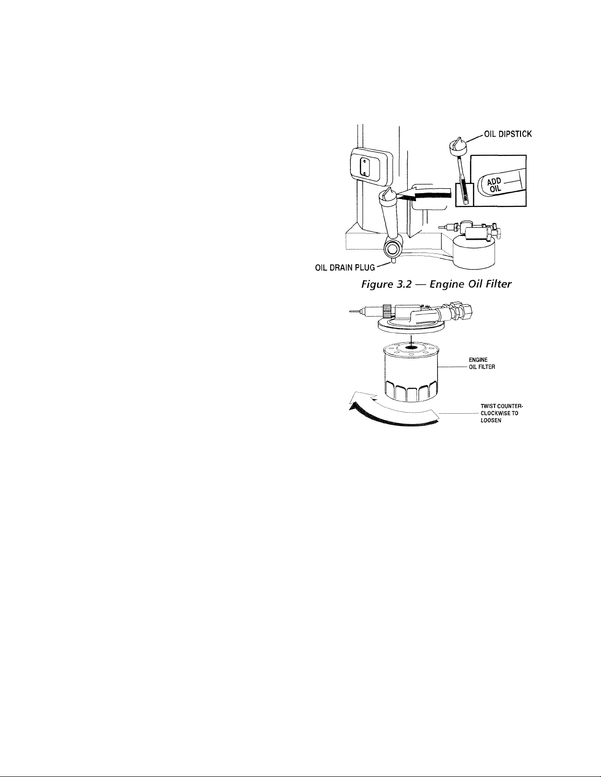
3.1
CHECKING THE ENGINE OIL
LEVEL
For oil capacities and requirements, see “Engine Oil
Requirements,” Section 1.6.2 (Page 6). Check the
engine crankcase oil level at least every eight hours of
operation, or before you use it. To check the engine
oil level, proceed as follows (see Figure 3.1):
Be sure the generator is as level as possible.
1.
Remove the dipstick and wipe it dry with a clean,
2.
lint-free cloth.
Install and tighten the dipstick cap; then, remove
3.
it again. The oil level should be at the dipstick
“Full” mark.
If necessary, remove the oil fill cap on the rocker
4.
cover and slowly adcf oil until it reaches the dip
stick “Full” mark. DO NOT FILL ABOVE THE
“FULL’ MARK.
-------
ik CAUTION Mk---------------
Never operate the engine with the oil level
A
below the "Add" mark on the dipstick. Doing
this could damage the engine.
5. Install and tighten the oil fill cap and the dipstick
before operating the engine.
Generac® Power Systems, Inc. 1 1
Page 14
MAINTENANCE
Section 3 - Maintenance
PRIMEPACT 70C and 70LP Recreational Vehicle Generators
3.2 CHANGING THE ENGINE OIL
AND/OR OIL FILTER
• Change the engine oil after the first 25 hours of
operation (after the 25-hour break-in period, see
Section 2.8.5, Page 10). Thereafter, change the
oil every 100 operating hours. Change the oil more
frequently if operating consistently under heavy
load or at high ambient temperatures.
• Change the engine oil filter after the first 25 hours
of operation, and every 100 operating hours there
after.
To change the oil and/or oil filter, proceed as
follows:
1. Run the engine until it is thoroughly warmed up
(at least five minutes) then shut OFF
the engine.
2. With (he engine still warm from running, remove
the oil drain plug (Figure 3.1). Drain the oil into
a suitable conlainer.
3. After the oil lias drained, replace the oil drain
plug. (II only changing the oil, go to step 7.)
4. With the oil drained, remove the old oil filter by
¡uming it counterclockwise (Figure 3.2 on page 12).
5. Apply a light coating of clean engine oil to the gas
ket of the new filter.
6. Screw the new filter on by hand until its gasket
lightly c'onlacts the oil filter adapter. Then, tight
en the filter an additional 3/4 to one turn.
7. Remove the dipstick and fill crankcase with the
jn oper type and amount of recommended oil (see
Seedion 1.6.2. Page 6). Tlie engine crankcase can
hold aboul 1.4 liters. DO NOT FILL ABOVE THE
d^TJLi: MARK.
c8. Install and lighten the dipstick before operating
tlu' engiiK'.
9. Start the engine and check for leaks.
NOTE:
Check the oil level and fill to the “FULE’ mark after
checking for leaks. The filter will retain some oil.
Figure 3.1 — Oil Dipstick/FiU Tube and
Location of Oil Drain Plug
3.3
MAINTAINING THE ENGINE
AIR CLEANER
♦ 3.5.1 CLEANING THE FOAM PRECLEANER
Clean and re-oil the foam precleaner every three
months or every 25 hours of operation, whichever
occurs first. Service the foam precleaner more fre
quently if operating the generator in extremely dusty
or dirty conditions. Use the following procedure
(Figure 3.3):
1. Turn the knob counterclockwise to loosen.
2. Remove the cover, foam precleaner and paper fil
ter.
3. Remove the foam precleaner from the cover.
4. Wash the foam precleaner in liquid detergent and
water.
5. Wrap the foam precleaner in a clean cloth and
gently squeeze it dry.
6. Saturate the foam precleaner in clean engine oil.
Genllv squeeze it in a clean cloth to remove
excess oil and to distribute oil (DO NOT TWIST).
7. Install the foam precleaner into the cover, fol
lowed by the paper filter. Tabs at edges of paper
1 H Generac’ Power Systems, Inc.
Page 15
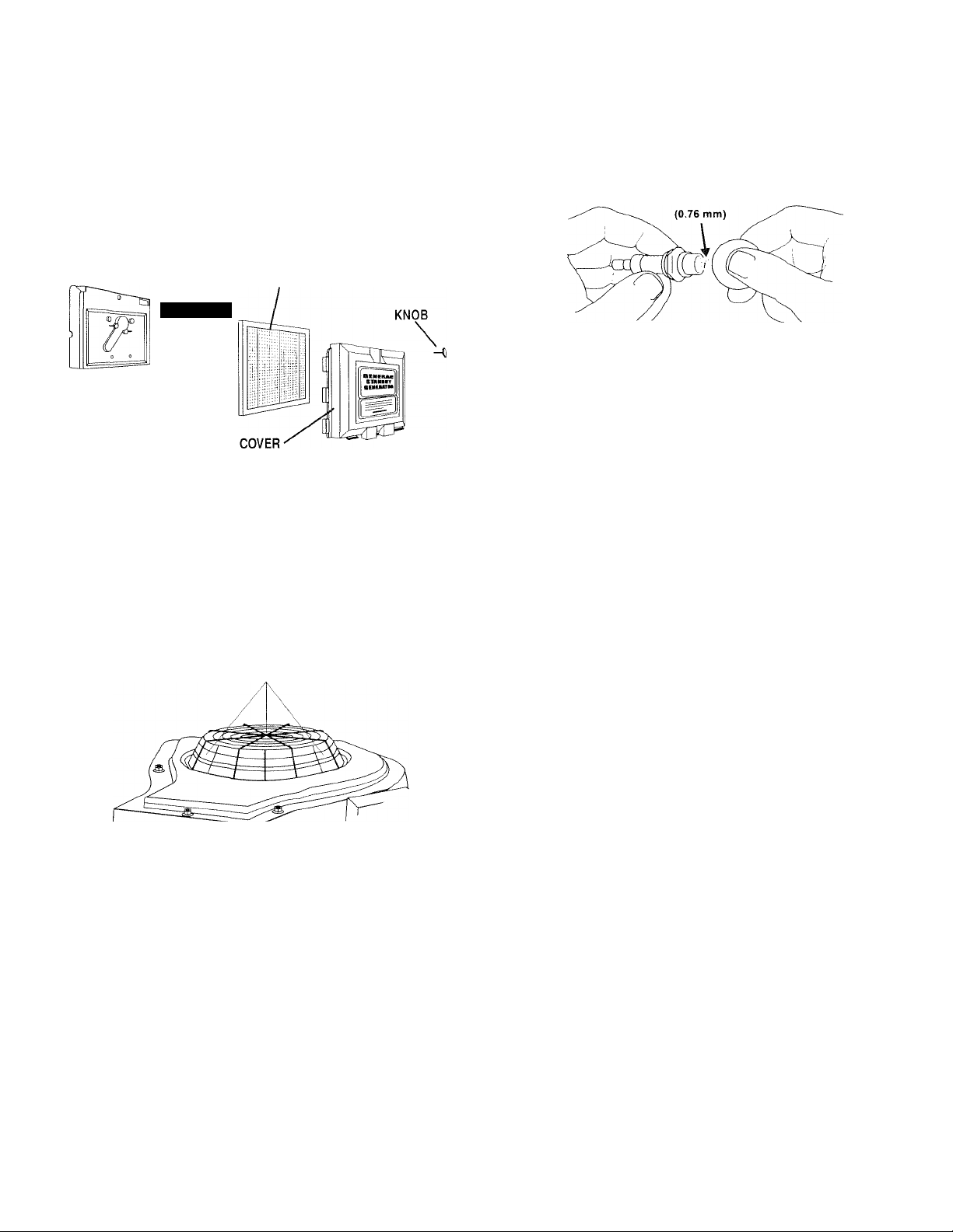
Section 3 - Maintenance
PRIMEPACT TOG and 70LP Recreational Vehicle Generators
MAINTENANCE
filter must lock into slots on cover.
8. Install the cover, foam precleaner and paper filter.
9. Replace knob to retain the filter in place.
Figure 3.3 - Engine Air Cleaner
PAPER
FILTER
FOAM
PRE-CLEANER
3.4 CLEAN AIR INTAKE SCREEN
Clean all foreign material from the air intake screen
(Figure 3.4) at least once every 100 hours of opera
tion. Clean more often if necessary.
Inspect the area around the generator exhaust muf
fler periodically and remove all grass, leaves, dirt,
etc., from this area.
Figure 3.5 - Setting the Spark Plug Gap
-------
ik CAUTION Mk
Sparking can occur if the wire terminal does
A
not fit firmly on the spark plug terminal end. If
necessary, re-form the wire terminal to obtain a
tight fit.
------------
3.6 FUEL FILTER (gasoline only)
Remove and replace the fuel filter (Figure 3.6)
once each year or every 100 hours of operation,
whichever comes first.
Figure 3.6 - Fuel Filter
FUEL FILTER
TO FUEL PUMP
Figure 3.4 - Cleaning Air Intake
CLEAN THESE AREAS
3.5 CHECKING THE ENGINE
SPARK PLUG
Clean the spark plug and reset the spark plug gap
every 100 hours of operation.
1. Clean the area around the base of the spark plug
to keep dirt and debris out of the engine. Clean by
scraping or washing using a wire brush and com
mercial solvent. Do not blast the spark plug to
clean.
2. Remove the spark plug and check the condition.
Replace the spark plug if worn or if reuse is ques
tionable.
3. Check the spark plug gap using a wire feeler
gauge. Adjust the gap to 0.030 inch (0.76 mm)
by carefully bending the ground electrode
(Figure 3.5).
CUSTOMER FUEL CONNECTION
3.7 SPARK ARRESTOR IVlUFFLER
If the generator is not equipped with a spark arrestor
exhaust muffler and is to be used on any forest cov
ered, brush covered or grass covered unimproved
land, you may have to install a spark arrestor. The
spark arrestor must be maintained in effective work
ing order by the vehicle owner/operator.
For assistance in ordering, installing and maintaining
spark arrestor exhaust mufflers, contact your nearest
Generac Authorized Service Dealer.
Exhaust mufflers supplied by Generac arc spark
arrestor types. Generac exhaust mufflers for recre
ational vehicle generators do not have a spark
arrestor screen, but are of the more efficient “toroid"
or “swirl" type. To remove carbon and combustion
deposits from such mufflers, remove the plug from
the muffler and run the engine for approximately 15
minutes. Shut down the engine, let the muffler cool
and install the plug.
Generac® Power Systems, Inc. 1 3
Page 16

iX>=
MAINTENANCE
Section 3 - Maintenance
PRIMEPACT 70G and 70LP Recreational Vehicle Generators
-----
ik WARNING Ék
Be sure to reinstall the muffler plug tightly.
A
Engine vibration could cause a loose plug to
fall out. Without the plug in place, hot engine
exhaust is directed out the opening. This hot
exhaust, depending on the installation, could
be directed to areas not able to withstand the
extreme heat such as wooden floor boards or
other flammable material. This could result in a
fire.
------
3.8 CLEANING THE GENERATOR
Keep the generator set as clean and dry as possible.
Protect the unit against excessive dust, dirt, corrosive
vapors, road splash, etc. Permitting dirt and mois
ture to accumulate on generator windings will have
an adverse effect on the insulation resistance of those
windings.
When moisture is allowed to remain in contact with
windings, some of the moisture will be retained in
voids and cracks in the insulation. This causes a
reduced insulation resistance and will eventually
cause problems. Dirt will make the problem worse,
since dirt tends to hold moisture in contact with
windings. Salt (as from sea air) also will worsen the
problem since it tends to absorb moisture from the
air. Salt and moisture, when combined, form a good
electrical conductor.
---------
Ml caution M
Do NOT use a forceful spray of water to clean
A
the generator. Water will enter the generator
interior and cause problems, and may also cont
aminate the generator fuel system.
-------------------
3.9 BATTERY MAINTENANCE
All lead-acid batteries will discharge when not in use.
The generator battery should be inspected as follows:
♦ 3.9.1 WEEKLY________________________________
• Inspect the battery posts and cables for tightness
and corrosion. Tighten and clean as necessary.
• Check the battery fluid level of unsealed batteries
and, if necessary, fill with Distilled Water Only. Do
not use tap water in batteries.
♦ 5.9.2 EVERY SIX MONTHS
• Have the state of charge and condition checked.
This should be done with an automotive-type bat
tery hydrometer.
Servicing of the battery is to be performed or
supervised by personnel knowledgeable of batter
ies and the required precautions. Keep unautho
rized personnel away from batteries.
1 «4 Generac’ Power Systems, Inc.
_______________________
NOTE:
Damage will result if the battery connections are
made in reverse.
DANGER
Do not dispose of the battery in a fire. The
battery is capable of exploding. Storage batter
ies give off explosive hydrogen gas. This gas
can form an explosive mixture around the bat
tery for several hours after charging. The
slightest spark can ignite the gas and cause an
explosion. Such an explosion can shatter the
battery and cause blindness or other injury.
Any area that houses a storage battery must be
properly ventilated. Do not allow smoking,
open flame, sparks, or any spark producing
tools or equipment near the battery. Discharge
static electricity from your body before touch
ing the battery by first touching a grounded
metal surface.
A battery presents a risk of electrical shock
A
and high short circuit current. The following
precautions are to be observed when working
on batteries:
• Remove watches, rings or other metal objects;
• Use tools with insulated handles;
• Wear rubber gloves and boots;
• Do not lay tools or metal parts on top of the
battery;
• Disconnect any charging source prior to connecting
or disconnecting battery terminals; and
• Do not use any jumper cables or booster battery to
crank and start the generator engine. If any battery
has discharged, remove it for recharging.
-----
LL WARNING ik
Do not open or mutilate the battery. Released
A
electrolyte has been known to be harmful to
the skin and eyes, and to be toxic.
The electrolyte is a dilute sulfuric acid that is
A
harmful to the skin and eyes. It is electrically
conductive and corrosive. The following
procedures are to be observed:
• Wear full eye protection and protective clothing;
• Where electrolyte contacts the skin, wash it off
immediately with water;
• Where electrolyte contacts the eyes, flush
thoroughly and immediately with water and seek
medical attention; and
• Spilled electrolyte is to be washed down with an
acid neutralizing agent. A common practice is to
use a solution of 1 pound (500 grams) bicarbonate
of soda to 1 gallon (4 liters) or water. The bicar
bonate of soda solution is to be added until the
evidence of reaction (foaming) has ceased. The
resulting liquid is to be flushed with water and the
area dried.
------
Page 17

Section 3 - Maintenance
PRIMEPACT TOG and 70LP Recreational Vehicle Generators
MAINTENANCE
3.10 MAJOR SERVICE MANUAL
To obtain a service manual for your generator, con
tact Generac or your nearest Generac Authorized
Service Dealer. Make sure to identify your MODEL
NUMBER and SERIES.
3.11 DRIVE BELT
The engine drives the generator rotor by means of a
pulley and drive belt arrangement. The drive belt and
pulleys are warranted for the life of the generator.
Drive belt tension was properly adjusted before the
unit was shipped from the factory. If you suspect that
drive belt tension is incorrect, contact a Generac
Authorized Service Dealer.
3.12 EXERCISING THE GENERATOR
Generac recommends that you start and operate the
generator at least once every seven days. Let
the unit run for at least 30 minutes to “exercise”
the engine.
3.13 OUT OF SERVICE PROCEDURE
♦ 5.13.1 REMOVAL FROM SERVICE
If you cannot exercise the generator every seven days,
and it is to be out of service longer than 30 days, pre
pare the generator for storage as follows:
1. Start the engine and let it warm up.
2. Close the fuel shutoff valve in the fuel supply line
and allow the unit to shut down.
3. While the engine is still warm from running,
drain the oil completely Refill the crankcase with
SAE lOW-30 oil having API classification “For
Service SE”
4. Attach a tag to the engine indicating the viscosity
and classification of the oil in the crankcase.
5. Remove the spark plug and pour two or three
tablespoons of clean, fresh engine oil into the
spark plug threaded openings. Reinstall and
tighten the spark plug.
6. Remove the battery and store it in a cool, dry
room on a wooden board. Never store the battery
on any concrete or earthen floor.
7. Clean and wipe the entire generator.
♦ 5.15.2 RETURN TO SERVICE____________________
To return the unit to service after storage, proceed
as follows:
1. Check the tag on the engine for oil viscosity and
classification. Verify that the correct recommend
ed oil is used in the engine (see Section 1.5.4,
Page 6). If necessary, drain and refill with the
proper oil.
________________
2. Check the state of the battery. Fill all cells of
unsealed batteries to the proper level with distilled
water. DO NOT USE TAP WATER IN THE BAT
TERY. Recharge the battery to 100 percent state of
charge, or, if defective, replace the battery.
3. Clean and wipe the entire generator.
4. Reconnect the battery. Observe battery polarity.
Damage may occur if the battery is connected
incorrectly.
5. Turn OFF all electrical loads. Add fuel if neces
sary and then start the engine.
6. Allow the unit to warm up thoroughly.
7. Apply electrical loads to at least 50 percent of the
unit’s rated wattage capacity.
8. When the engine is thoroughly warmed up, shut
it down.
9. Your generator is now ready for service.
3.14 WATTAGE REFERENCE GUIDE
Running Watts
Battery Charger.................................................................500
Belt Sander (3")
Chain Saw.......................................................................1200
Circular Saw (6-12”)
Disc Sander (9”) .............................................................1200
Hand Drill (1”) ...............................................................1100
Hedge Trimmer.................................................................450
Impact Wrench .................................................................500
Lawn Mower ..................................................................1200
Electric Range (one element)..........................................1500
Television........................................................1750 to 2000
Coffee Maker
Electric Skillet.................................................................1250
Hair Dryer
Light Bulb.........................................................................100
Microwave Oven ..............................................................700
Oil Burner on Furnace
Oil Fired Space Heater (140,000 Btu)
Radio......................................................................50 to 200
Slow Cooker .....................................................................200
♦Furnace Fan (1/3 HP)....................................................1200
♦Refrigerator.....................................................................600
♦Air Conditioner (12,000 Btu)........................................1700
♦Compressor (IHP).........................................................2000
♦Deep Freeze
♦Milk Cooler ..................................................................1100
♦Submersible Pump (1-1/2 HP)
♦Submersible Pump (1 HP)
♦Paint Sprayer, Airless (1/3 HP)
♦Table Saw (10”) ...........................................1750 to 2000
♦ Allow 2-1/2 times the listed watts for starting these
devices.
..............................................................
........................................
..................................................................
.......................................................................
.....................................................
..............................
....................................................................
.............................
............................................
..............................
Generac* Power Systems, Inc. 1 5
800 to 1000
1000
1000
1200
300
400
500
2800
2000
600
Page 18

NOTES
Section 4 - Notes
PRIMEPACT 70G and 70LP Recreational Vehicle Generators
1 B Generac* Power Systems, Inc.
Page 19

PART II -
INSTALLATION
INSTRUCTIONS
DANGER
ONLY QUALIFIED ELECTRICIANS OR CONTRACTORS
SHOULD ATTEMPT INSTALLATION!!
Page 20

SAFETY RULES
DANGER: For fire safety, installation of a generator into a recreational vehicle must comply strictly
with article 551, NFPA 70; ANSI Cl-1975; AND, ANSI A119.2-1975/NFPA 501C “Standard for
Recreational Vehicles’’ (Part 3, “Installation of Electrical Systems"). In addition, installation must
comply with the manufacturer’s instructions and recommendations.
Safety Rules
PRIMEPACT 70G and 70LP Recreational Vehicle Generators
NOTICE TO INSTALLER
These I ns tal lat ion In str uc tio ns have been published
by Generac to aid in the installation of the products
described in this manual. Generac assumes that
installation personnel are familiar with the proce
dures for installing such products, or similar prod
ucts that Generac manufactures. Generac also
assumes that personnel have been trained in the rec
ommended installation procedures for these prod
ucts and that such training includes (a) use of com
mon hand tools, (b) use of special Generac tools, and
(c) use of any tools and/or equipment from other sup
pliers.
Generac cannot possibly know of and advise the
recreational vehicle trade of all conceivable methods,
procedures or techniques by which to perform an
installation. Nor can Generac anticipate every possi
ble hazard that might result from each installation
method, procedure or technique. Generac has not
undertaken any such wide evaluation. Therefore,
people who use a method, procedure or technique
that Generac does not specifically recommend must
first completely satisfy themselves that their safety,
the safety of the vehicle's occupants and the product's
safety is not endangered by the method, procedure or
technique selected.
Information, illustrations, specifications, etc., con
tained in these In sta lla tio n In str uc tio ns are based on
the latest information available at the time of publi
cation. Every efforl has been expended to be sure that
such data is both accurate and current. However, the
manufacturer reserves the right to change, alter or
otherwise improve this product at any time without
prior notice.
DANGER
Despite the safe design of this generator,
operating this equipment imprudently, neglecting
its maintenance or being careless can cause
possible injury or death. Permit only responsible
and capable persons to operate or maintain this
equipment.
Potentially lethal voltages are generated by
A
these machines. Ensure all steps are taken to
render the machine safe before attempting to
work on the generator.
Parts of the generator are rotating and/or hot
during operation. Exercise care near running
generators.
A GENERAL HAZARDS A
For safety reasons, Generac recommends
that the installation, initial start-up and mainte
nance of this equipment is carried out by a
Generac Authorized Service Dealer.
The engine exhaust fumes contain carbon monox
ide, which can be DEADLY. This dangerous gas, if
breathed in sufficient concentrations, can cause
unconsciousness or even death. This exhaust sys
tem must be installed properly, in strict compli
ance with applicable codes and standards.
Following installation, you must do nothing that
might render the system unsafe or in noncompli
ance with such codes and standards. The genera
tor compartment must be completely vapor sealed
from the vehicle interior. There must be no possi
bility of exhaust fumes entering the vehicle interi
or. Never operate this equipment with a leaking or
defective exhaust system.
Keep hands, feet, clothing, etc., away from drive
belts, fans, and other moving or hot parts. Never
remove any drive belt or fan guard while the unit is
operating.
Adequate, unobstructed flow of cooling and venti
lating air is critical to correct generator operation
and is required to expel toxic fumes and fuel
vapors from the generator compartment. Without
sufficient cooling airflow, the engine/generator
quickly overheats, which causes serious damage to
the generator. Do not alter the installation or per
mit even partial blockage of ventilation provisions,
as this can seriously affect safe operation of the
generator.
When working on this equipment, remain alert at
all times. Never work on the equipment when you
are physically or mentally fatigued.
Before performing any maintenance on the genera
tor, disconnect its battery cables to prevent acci
dental start up. Disconnect the cable from the bat
tery post indicated by a NEGATIVE, NEG or (-)
first. Reconnect that cable last.
Never use the generator or any of its parts as a
step. Stepping on the unit can stress and break
parts, and may result in dangerous operating con
ditions from leaking exhaust gases, fuel leakage,
oil leakage, etc.
Never insert any tool or other object through open
ings in the generator interior, even if the unit is not
running. You might seriously Injure yourself or
damage the equipment.
1 S Generac* Power Systems, Inc.
Page 21

Safety Rules
PRIMEPACT 70G and 70LP Recreational Vehicle Generators
SAFETY RULES
A
ELECTRICAL HAZARDS
The generator covered by this manual produces
dangerous electrical voltages and can cause fatal
electrical shock. Avoid contact with bare wires, ter
minals, connections, etc., while the unit is running.
Ensure all appropriate covers, guards and barriers
are in place before operating the generator. If you
must work around an operating unit, stand on an
insulated, dry surface to reduce shock hazard.
Do not handle any kind of electrical device while
standing in water, while barefoot, or while hands
or feet are wet. DANGEROUS ELECTRICAL
SHOCK MAY RESULT.
During installation onto the vehicle, properly
ground (bond) the generator either by solid mount
ing to the vehicle frame or chassis, or by means of
an approved bonding conductor. DO NOT connect
the bonding conductor to any generator part that
might be removed or disassembled during routine
maintenance. If the grounding conductor must be
replaced, use only a flexible conductor that is of
No. 8 American Wire Gauge (AWG) copper wire
minimum.
If the vehicle electrical circuits can be powered by
any other source of electricity (such as a "dockside” power receptacle), there must be no possibil
ity of connecting the different power sources to the
vehicle circuits at the same time. The dockside
(utility) power source must be positively isolated
from the vehicle circuits whenever the generator is
operating. Failure to isolate the vehicle circuits
from the dockside power supply when the genera
tor is running may result in damage to the genera
tor or serious injury or death to dockside (utility)
power workers due to backfeed of electrical ener
gy-
In case of accident caused by electric shock, imme
diately shut down the source of electrical power. If
this is not possible, attempt to free the victim from
the live conductor. AVOID DIRECT CONTACT
WITH THE VICTIM. Use a nonconducting imple
ment, such as a rope or board, to free the victim
from the live conductor. If the victim is uncon
scious, apply first aid and get immediate medical
help.
Never wear jewelry when working on this equip
ment. Jewelry can conduct electricity resulting in
electric shock, or may get caught in moving com
ponents causing injury.
A
A
FIRE HAZARDS
For fire safety, the generator must be installed and
maintained properly. Installation always must
comply with applicable codes, standards, laws and
regulations. Adhere strictly to local, state and
national electrical and building codes. Comply
with regulations the Occupational Safety and
Health Administration (OSHA) has established.
Also, ensure that the generator is installed in
accordance with the manufacturer’s instructions
and recommendations. Following proper installa
tion, do nothing that might alter a safe installation
and render the unit in noncompliance with the
aforementioned codes, standards, laws and regu
lations.
Keep a fire extinguisher in the vehicle at all times.
Extinguishers rated “ABC" by the National Fire
Protection Association are appropriate for use on
the recreational vehicle generator electrical system.
Keep the extinguisher properly charged and be
familiar with its use. If you have any question per
taining to fire extinguishers, consult your local fire
department.
A
EXPLOSION HAZARDS
Do not smoke around the generator. Wipe up any
fuel or oil spills immediately. Ensure that no com
bustible materials are left in the generator com
partment, or on or near the generator, as FIRE or
EXPLOSION may result. Keep the area surround
ing the generator clean and free from debris.
Gasoline is extremely FLAMMABLE and its vapors
are EXPLOSIVE. Do not permit smoking, open
flame, sparks or any source of heat in the vicinity
while handling gasoline. Comply with all laws gov
erning the storage and handling of gasoline.
Fuel lines must be properly installed and
fastened, and free of leaks. There must be
no possibility of gasoline vapors entering the vehi
cle interior.
You are required to install an approved, flexible,
nonconductive fuel line between the generator fuel
connection point and rigid fuel lines.
If the generator is equipped with a liquid propane
(LP) gas fuel system, install the unit so it complies
with all codes, standards and regulations pertain
ing to such systems. LP gas is highly explosive. The
gas tends to settle in low areas where even the
slightest spark can ignite it and cause an explo
sion. Do not allow gas vapors to enter the vehicle.
A
A
Generac* Power Systems, Inc. 1 3
Page 22
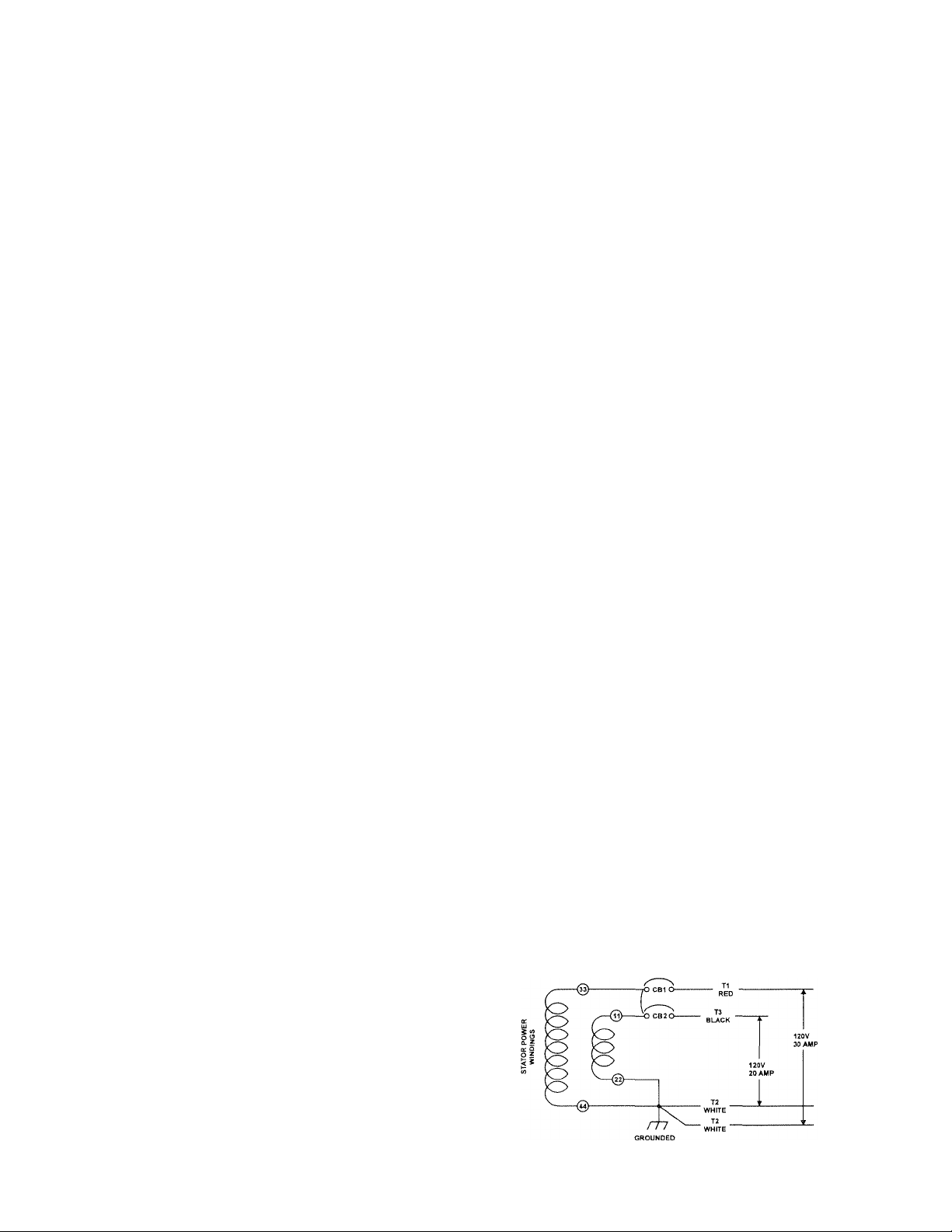
GENERAL
INFORMATION
Section 5 - General Information
PRIMEPACT 70G and 70LP Recreational Vehicle Generators
5.1 PURPOSE AND SCOPE OF THE
INSTALLATION INSTRUCTIONS
These Inst al lat ion In st ru cti on s have been prepared
especially for the purpose of familiarizing installers and
owners of the applicable equipment with the product's
installation requirements. Give serious consideration to
all information and instructions in the manual, both for
safety and for continued reliable operation of the equip
ment.
Because of the different recreational vehicle models and
the variations between the models, it would be extremely
difficult, if not impractical, to provide detailed instruc
tions for every possible installation. For that reason,
instructions and illustrations in this manual are general
in nature. Illustrations are not intended to serve as
detailed installation blueprints.
The installation should comply strictly with all applica
ble codes, standards and regulations pertaining to the
installation and use of this product. If any portion of
this manual appears to be in conflict with such codes,
standards or regulations, the applicable codes, stan
dards or regulations must take precedence over the
manual.
5.2 SAFETY
Before handling, installing, operating or servicing this
equipment, carefully read the “Notice to Installer” and
“Safety Rules” on Pages 18 and 19. Comply with all safe
ty rules to prevent death, personal injury or damage to
equipment and/or property. Stress safety to all
installers, operators and service technicians who work
on this equipment.
5.3 STANDARDS BOOKLETS
Installation, use and servicing of this equipment should
comply strictly with published standards, as well as the
manufacturer's recommendations. The following stan
dards Irooklets (latest revision) are available from the
sources indicated:
1.
NFPA Standard 501C, “Standard for Recreational
Vehicles,” available from the National Fire
Protection Association, Batterymarch Park, Quincy,
MA 02269.
2.
NFPA 70, “NFPA Handbook of the National Electric
Code," available same as Item 1.
ANSI Cl-1975 and ANSI 119.2-1975, available from
the American National Standards Institute, 1430
Broadway, New York, NY 10018,
4.
ANSI A119.2/NFPA 501C, available from the
Recreational Vehicle Association, 1896 Preston
White Drive, Reston, VA 22090.
5.
California Administrative Code, Title 25, available
from the State of California, Documents Section,
PO. Box 1015, North Highlands, CA 95660.
6. eSA Electrical Bulletin 946, available from the
Canadian Standards Association, Housing and
Constructions Materials Section, 178 Rexdale
Boulevard, Rexdale, Ontario, Canada, M9W 1R3.
5.4 EQUIPIVIENT DESCRIPTION
Instructions and information in this section pertain to
Generac air-cooled generators. These generators are
designed specifically for installing in recreational vehi
cles. They operate 120-volt, single-phase, 60-Hertz, AC
electrical loads that require 58.3 amps (gasoline) or
55.0 amps (LP fuel) at 120 volts.
5.5 GENERATOR ENGINE
OPERATING SPEED
The generator’s revolving field (rotor) is driven by a twocylinder, four-cycle engine through a pulley and drive
belt arrangement. The generator supplies 120 volts AC
at 60 Hertz when the rotor is operating at 3,600
rpm.The drive belt arrangement allows the engine to
operate at a lower speed than the rotor.
5.6 GENERATOR AC
CONNECTION SYSTEIVi
These air-cooled generator sets are equipped with dual
stator AC power windings. These two stator windings
supply electrical power to customer electrical loads by
means of a dual 2-wire connection system.
Generators may be installed to provide the following
outputs:
1) 120 VAC loads only — one load with a maximum total
wattage requirement equal to the generator’s rated
power output (in watts), and 120V across the generator
output terminals.
2) 120/240 VAC loads — one load with a maximum total
wattage requirement equal to the generator’s rated
power output, and 240 V across the generator output
terminals: or two seperate loads, each with a maximum
total wattage requirement equal to half of the genera
tor’s rated power output (in watts), and 120 V across
the generator output terminals.
Figure 5.1 - Connection for 120 Volts Only
S.O Generac* Power Systems, Inc.
Page 23
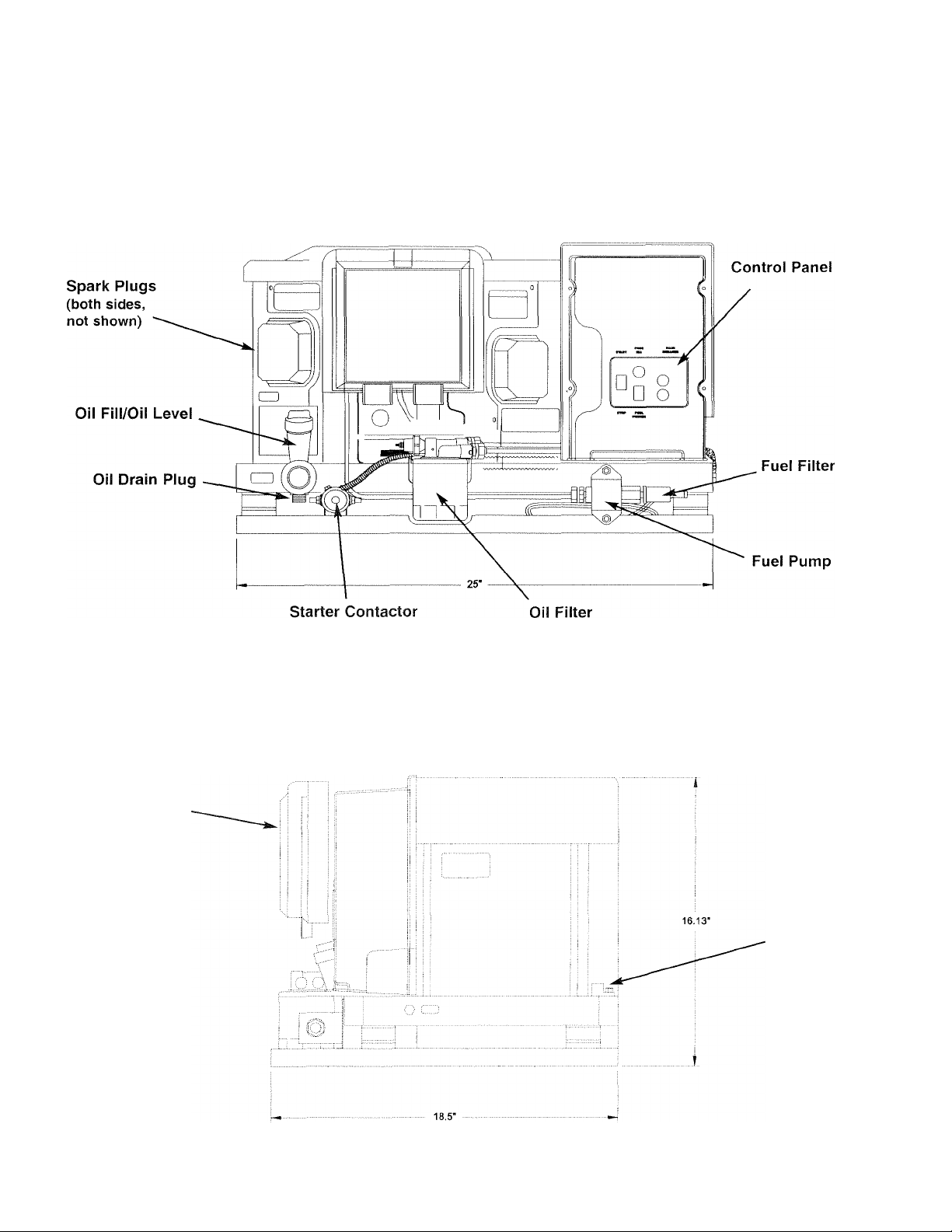
Section 5 - General Information
PRIMEPACT 70G and 70LP Recreational Vehicle Generators
Figure 5.2 - Major Features and Dimensions
PRIMEPACT 70G and 70LP
GENERAL
INFORMATION
Air Filter
Ground Lug
Generao* Power Systems, Inc. 21
Page 24
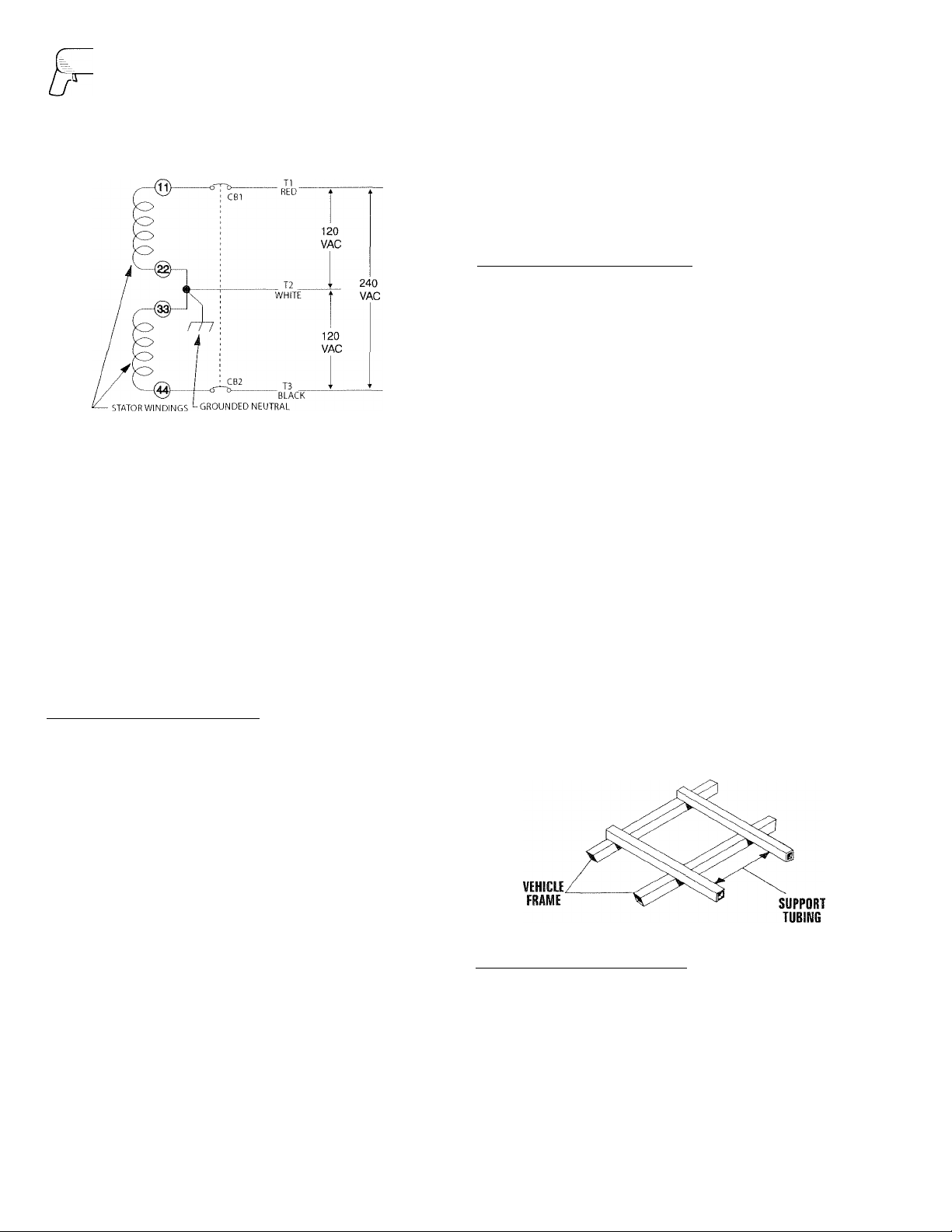
INSTALLATION
:>
Section 6 - Installation
PRIMEPACT 70G and 70LP Recreational Vehicle Generators
Figure 5.3 - Connection for 120/240 Volts
• The AC connection system on all air-cooled
PRIMEPACT series generators uses a GROUNDED
neutral.
• A separate green ground wire is connected to the
recreational vehicle's junction box.
• Loads connected across T1 (Red) to T2 (White), and
T3 (Black) to T2 (White), must not exceed 58.3 amps
for PriinePact 70G, or 55 amps for PrimePact 70LP
with a voltage of 120V across each set of terminals.
NOTE:
Do NOT connect loads in excess of circuit
breaker ratings.
6.1 LOCATION AND SUPPORT
• 6.1.1 GENERATOR LOCATION
I'lie most desirable location for the generator set is
between the veliicle's main frame members. However,
this is seldom jjossilrle. Most units must be installed on
the side of the vehicle and are difficult to reinforce.
Many recreational vehicles have been factory equipped
with an area for the generator set. Some vehicles may
even have a generator compartment provided by the
vehicle manufacturer.
Plan the generator location based on the following:
• The generator set must be installed on a framework
that is part of the recreational vehicle, as outlined in
Section 6.1.2.
• The location must provide an access opening that is
large enough to permit generator removal (unless the
generator is to be removed from underneath the sup
porting framework).
• The location must provide easy access to frequently
serviced components, such as filters, oil drains,
spark plugs and other common maintenance parts.
• The location must provide sufficient room to allow
minimum clearances as outlined in Section 6.2. If
sound insulation is to be used on the compartment
___________________
_
walls and ceiling, the minimum recommended
applies to the space between the generator and such
insulation.
• The location must provide adequate cooling and ven
tilating airflow for the generator without a great deal
of work and expense.
• 6.1.2 GENERATOR SUPPORT
_____________________
The generator must be securely attached to a metal
framework that has been made part of the vehicle frame
structure by bolting or welding. The metal framework
on which the generator will rest and which will restrain
the generator set should consist of at least two horizon
tal beams. These beams should consist of (a) 1-1/2-inch
square, 11-gauge steel tubing OR (b) 1-1/2-inch, 11-
gauge angle iron. A typical supporting frame with hori
zontal support tubing, is shown in Figure 6,1,
The generator can be installed so that it sits on top of
the horizontal support tubing if the vehiele design per
mits. Another method is to suspend the generator below
the horizontal support tubing by means of suitable,
structurally sound metal framework. The following gen
eral rules apply:
“ Vehicle construction MUST be capable of supporting
the weight of the generator.
• 'Whether the generator is mounted above the horizon
tal support tubing or suspended below the tubing, the
supporting frame used must be structurally sound.
' If the generator cannot be bolted directly to
the supporting frame or support tubing, consider
using additional tubing, angle brackets
or other supports to give the supporting frame suffi
cient strength.
Figure 6.1 - Typical Horizontal Support Frame
♦ 6.1.5 SUSPENDED MOUNTING
______________________
If you are going to suspend the generator below the hor
izontal support tubing, the suspension method you use
with the vehicle frame members must (a) be able to sup
port the weight of the generator AND (b) provide suffi
cient restraint for the generator. One typical suspended
mounting system is shown in Figure 6.2. The location of
a suspended mounting system must be carefully
planned, keeping the following general rules in mind:
SS Generac* Power Systems, Inc.
Page 25
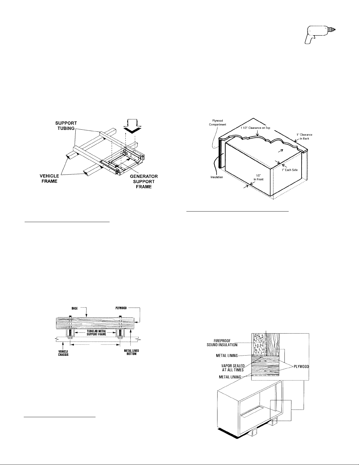
Section 6 - Installation
PRIMEPACT 70G and 70LP Recreational Vehicle Generators
INSTALLATION
Protect the generator against road splash and debris.
Baffles or splash guards may be required to protect cer
tain ai'eas of the generator. To make sure the generator
is adequately protected, road test the installation
through mud, water and slush.
Figure 6.2 - Typical Suspended Mounting System
GENERATOR MOUNTING
HOLES FOR 3/8" -16
BOLTS (BOTH SIDES)
• The installer must make certain that the selected
location will permit adequate cooling and ventilating
airflow to be supplied.
♦ 6.1.4 GENERATOR RESTRAINT
____________________
Use four 3/8"-16 hardened steel bolts (Grade 5) to fasten
the generator to the supporting frame or the support tub
ing. These bolts must pass through (a) the generator
mounting base, (b) the compartment floor (if a compart
ment is used) and (c) the supporting framework
(Figure 6.3). /Ml bolts must be long enough so that when
tight, at least three threads are visible past the retaining
lock nuts. Refer to Section 6.2 for the location of the gen
erator mounting holes.
Figure 6.3 - Typical Generator Restraint
1/2 INCH THICK
from ilic back lor air circulation AFTER the compart
ment has been lined with metal and sound insulalioii
(Figure 6.4).
NOTE:
Refer to “Figure 5.2 -
Major Features and
Dimensions” on Page 21.
Figure 6.4 - Clearances
• 6.2.2 COMPARTMENT CONSTRUaiON
_______________
• The generator compartment should be either con
structed of, or lined with, 26-gauge galvanized steel.
NOTE:
Aluminum is NOT an acceptable alternative
to galvanized steel due to aluminum’s low
melting point.
• If the compartment is lined with galvanized steel, it
may be constructed of any material. Generac recom
mends that the compartment be constructed of 1/2inch thick plywood (not strandboard), with the floor
made of a double thickness of 1/2-inch plywood with
the grain of the wood at cross section for added
strength (Figure 6.5).
6.2 GENERATOR COIVIPARTIViENTS
Wlrether the generator set is being installed inside a com
partment specifically manufactured to house a generator
or inside a compartment that the installer constructs, the
compartment MUST meet certain specifications as out
lined in the following sections:
♦ 6.2.1 COMPARTMENT SIZE
Plan the compartment size carefully. Provide a mini
mum clearance of 1/2 inch (13 mm) on the front and
top, 1 inch (25 mm) on the sides, and 1/2 inch (13 mm)
________________________
Figure 6.5 - Typical Compartment Construction
CROSS SECTION VIEW
Generac* Power Systems, Inc. 23
METAL LINING
Page 26

INSTALLATION
Section 6 - Installation
PRIMEPACT 70G and 70LP Recreational Vehicle Generators
• If constructing a compartment, line the exterior
(underside) of the compartment floor with 26-gauge
galvanized steel.
• All seams, splices and joints of the compartment
walls (unless vapor tight by design) should be
caulked to prevent poisonous, flammable or explo
sive vapors from entering the vehicle interior.
NOTE:
Caulking must be done so that the caulking material
will stay in place permanently. Pressing such materi
als as putty tape onto joints and seams is not accept
able. A high quality silicone rubber base sealant is
recommended.
• Holes and openings made in the compartment walls
to allow for the passage of electrical conduit, conduc
tors, hoses, cables, etc., into the vehicle living area
must be sealed vapor tight with silicone rubber base
sealant.
• If flexible metal conduit is used, it must be sealed
internally at the end where it terminates inside the
compartment’s electrical junction box.
NOTE:
Flexible metal conduit, due to its unique construc
tion, is NOT vapor tight along its entire length.
• Seams and joints of the galvanized steel (whether
used as a liner or for the compartment itself) must be
lapped and mechanically secured. Such seams may
be manufactured, welded, bolted, riveted or screwed.
Manufactured lock seams are shown in Figure 6.6.
Installer constructed compartments t3q3ically utilize a
standard lap joint.
Figure 6.6 - Types of Lock Seams
. w p
FOLD LOCKED STANDING
I I
* ■ OFF SET
DOUBLE LOCK DOUBLE SEAM
STANDARD LAP JOINT
OFF SET
ACME LOCK
LOCK SEAM
After the compartment has been metal lined and
vapor sealed, line the compartment interior walls and
ceiling with an approved, nonflammable sound insu
lating material. See Section 6.2.3.
DANGER
Do not install any flammable material directly
A
above or around the compartment. Heat,
24 Qenerac* Power Systems, !nc.
transferred through the compartment structure,
may be sufficient to ignite, char or discolor
seat cushions, fiberboard and other flammable
materials. You may need to use approved
nonflammable insulating materials in high
temperature areas.
♦ 6.2.3 SOUND INSULATING MATERIALS
______________
Once installers have determined that a compartment is
properly constructed and metal lined, they can add
acoustical material. This may include additional sealant
or insulating material, to reflect noise away from the
vehicle Interior.
Sound insulating materials should be of a nonflamma
ble type. One excellent insulating material is a 1-inch
(25 mm) thick fiberglass having a 2-pound density.
When fiberglass is used, its coated side should face
toward the compartment interior.
DANGER
Do not install sound insulation or any absorbent
A
material on the compartment floor interior. Such
materials will become soaked with combustible or
explosive vapors and liquids and will become a
fire hazard.
Using a combination of sound insulating materials can
often reduce noise more effectively than a single mater
ial. For example, a sheet of lead or visco-elastic materi
al, along with a layer of other acoustical material, is
more effective than when a single material is used.
• 6.2.4 ACOUSTICS _____________
For additional noise abatement, the installer may wish
to consider the following:
• Using special sound insulating materials,
• Construction of a special noise abatement compart
ment.
NOTE:
Any method used to reduce noise must not adverse
ly affect the flow of cooling and ventilating air into or
out of the compartment.
In addition to the effective use of sound insulating mate
rials, construction of a special noise abatement com
partment might be considered to reduce noise levels.
Such a compartment might be constructed as follows
(Figure 6.7, page 25):
• Use 5/8-inch thick or 3/4-inch thick plywood in the
compartment.
• Construct the compartment floor of a double thick
ness of 5/8-inch or 3/4-inch plywood.
• Line the compartment interior walls and floor, as well
as the underside of the floor, with 26-gauge galva
nized steel.
Page 27

Section 6 - Installation
PRIMEPACT 70G and 70LP Recreational Vehicle Generators
INSTALLATION
Vapor seal all compartment seams and joints.
Over the galvanized steel lining, install a combination
of acoustical materials as mentioned in Section 6.2.3.
DANGER
To prevent fire or explosion, do not install any
A
insulation or other absorbent materials on the
interior or underside of the compartment floor.
• Seal all compartment door edges to prevent noise
leakage around the door perimeter.
• Line the compartment door interior (except for air
openings) with suitable, fireproof sound insulation
(such as 1-inch (25 mm) thick fiberglass with a 2pound density).
Figure 6.8 — Compartment Floor Cutout
Figure 6.7 - Typical Noise Abatement
Page 28

INSTALLATION
Section 6 - installation
PRIMEPACT 70G and 70LP Recreational Vehicle Generators
• 6.2.5 COMPARTMENT FLOOR CUTOUTS
You must provide openings in the generator compart
ment for the following items (Figure 6.8, Page 25):
• Engine exliaust and cooling air outlets
• Generator cooling air inlet
• Four holes for passage of generator mounting bolts.
See Section 6.1.4 (Page 23).
_____________
E2ANGER
Fuel lines and exhaust piping must not penetrate
A
into the vehicle living area.
6.3 COOLING AND VENTILATING AIR
It is absolutely essential that an adequate flow of air for
cooling, ventilating and engine combustion be supplied
to the generator set. Without sufficient airflow, the
engine/generator quickly overheats. Such overheating
can cause serious operating difficulties and also may
cause fire and personal injury. The installer must make
sure that sufficient air is available to the generator for
cooling, ventilating and combustion. The installer also
must provide for a path for exhausting the cooling air to
the exterior of a compartment, if so equipped.
♦ 6.3.2 COOLING AIR INLET OPENINGS
The minimum size of the air inlet opening, whether the
generator is housed in a conventional compartment or
not, is at least 100 square inches (see Figure 6.10).
This rule applies whether inlet air is brought in through
an opening in the compartment door, an opening in the
vehicle skirt, through ductwork, or by any other means.
NOTE:
Screening, louvers or expanded metal that cover air
openings restrict airflow. You must compensate for
this by making the actual air opening proportionate
ly larger. See Section 6.3.3 (Page 27).
Figure 6.10 - Air Inlet in Compartment Door
100 SQUARE INCHES
UNRESTRICTED
MINIMUM OPENINGS
________________
DANGER
Never use discharged cooling air for heating or
A
permit such air to enter the vehicle interior. This
air contains deadly carbon monoxide gas and
other poisonous, flammable or explosive gases.
♦ 6.3.1 GENERATOR AIRFLOW
Engine operation drives cooling fans for the two-stage
cooling air system. A pressure fan draws cooling air into
the top of the generator (Figure 6.9). This airflow cools
the engine/generator and electronic components. The
second part of the cooling system, a suction fan, draws
air that is heated from a hot engine into a collector pan
at the base of the unit. This heated air (although cooler
than exhaust muffler) is then deflected out the bottom
toward the ground.
Figure 6.9 - Airflow Through Engine/Generator
NOTE:
Be sure to meet the minimum clearances illustrated
in Figure 6.4 (Page 23).
When the unit is installed on a suspended mounting
system, one of several different methods of supplying
airflow may be used as follows:
• Provide a door in the vehicle skirt having an air inlet
opening (Figure 6.11).
Figure 6.11 - Suspended Mount: Inlet Door
Using ductwork (Figure 6.12, Page 27). The installer
must be sure air is available to the top of the genera
tor since air inlets are located at the top.
By providing an opening in the vehicle skirt and space
Page 29

Section 6 - Installation
PRIMEPACT TOG and 70LP Recreational Vehicle Generators
INSTALLATION
behind the generator for cooling airflow
(Figure 6.13 ). Recommended clearance behind the
back of the generator is at least 1/2 inch (13 mm).
Figure 6.12 - Air Inlet Using Ductwork
ANTI-SPLASH
Figure 6.13 - Air Inlet in Vehicle Skirt
♦ 63.4 TESTING THE INSTALLATION
__________________
Generac recommends testing the installation to be sure
adequate cooling airflow is available to the unit before
placing the unit into service. If the unit shows signs of
overheating, you will need to enlarge the air openings.
Never place a unit into service until absolutely certain
that cooling and ventilation is adequate.
NOTE:
You must test the installation, especially if you bring
in air from below the generator set.
6.4 GASOLINE FUEL SYSTEIV!
The installation of a gasoline fuel system (Figure 6.14)
for a recreational vehicle generator set must comply
with applicable codes, standards and regulations. The
entire fuel system must be completely free of leaks.
There must be no possibility of gasoline vapors entering
the vehicle interior.
Figure 6.14 - Generator Fuel System
♦ 6.3.5 COMPENSATING FOR RESTRICTIONS
Such materials as screening, louvers or expanded metal
can restrict the free flow of air. Compensate for this
restriction by making the actual air opening propor
tionately larger.
Some materials may offer only a 60 percent “free air
inlet area.” Other more efficient materials may provide
up to a 90 percent free air inlet area. The percentage of
free air inlet opening is usually available from the mate
rial supplier or manufacturer.
To determine the actual air inlet opening size
required, divide 100 square inches by the percent
age of free air inlet area for the material you will use.
For example: If you plan to use screening with an 80
percent free air inlet area, divide 100 by 0.8, which
results in 125 square inches. Minimum actual size of
air inlet opening in this case is 125 square inches.
DANGER
Gasoline is highly flammable, and its vapors are
explosive. Comply with all codes, standards and
regulations pertaining to gasoline fuel systems
used in recreational vehicle generators. Properly
install and maintain the fuel system and keep it
entirely free of leaks. Gasoline vapors must not
enter the vehicle interior.
Factory installed generator fuel system components
include (a) fuel filter, (b) 12-volt DC electric pump, (c)
engine carburetor, and (d) interconnecting lines and fit
tings. Connect a fuel supply line to the fuel filter inlet.
Use a flexible length of approved fuel hose between the
fuel filter inlet connection and rigid fuel lines.
Generac* Power Systems, Inc. S.7
Page 30

INSTALLATION
Section 6 - Installation
PRIMEPACT 70G and 70LP Recreational Vehicle Generators
♦ 6.4.1 FUEL TANK
Either tlie generator must share the vehicle engine's fuel
tank, or you must install a separate fuel tank for the
generator set. All fuel tanks installed on the vehicle
must be constructed, installed and restrained so they
comply with applicable codes, standards and regula
tions.
If the generator is to share the vehicle engine's tank, sep
arate fuel pickup tubes are required for the engine and
the generator. Generac recommends that you make the
fuel pickup tube 2 to 3 inches (51 to 76 mm) shorter
than the vehicle engine's pickup tube. This prevents the
generator from depleting the entire fuel supply during
prolonged generator operating periods.
-------
-Jk CAUTION
Do NOT tee the generator fuel supply line into
A
the vehicle engine fuel supply line. If this is done,
the generator will be starved of fuel when both
engines are operating at the same time. Also,
while the vehicle engine is not running, generator
operation may drain the vehicle engine supply
line, making it difficult to start the vehicle engine.
♦ 6.4.2 GENERATOR FUEL SUPPLY LINE
6.4.2.1 Rigid Fuel Lines
Those lines used to supply fuel from a tank to the gen
erator must comply with applicable codes, standards
and regulations. The following general rules apply to
rigid fuel lines:
• Rigid lines should be of annealed, seamless, drawn
aluminum or steel.
• Lines and fittings must comply with SAE J512F,
“Standard Automotive Fittings,” or with ANSI
B126.26 (latest edition).
• Route the fuel line so that at least 2 inches (51 mm)
of clearance is maintained between the line and any
exhaust system parts.
• Do not attach electrical wiring to fuel lines. Route the
wiring so it cannot come into contact with any fuel
line.
• Route fuel lines so if they leak, fuel does not drip onto
any electrical or exhaust system parts.
• Use nonferrous metal straps without sharp edges to
secure fuel lines.
--------------
_______________
• The hose should be at least 6 inches (152 mm) longer
than is needed to prevent the hose from rupturing if
the generator shifts or settles,
6.5 LP CAS FUEL SYSTEM
—AEaEia A—
lp gas is highly EXPLOSIVE. The gas is heavier
A
than air and tends to settle in low areas. Even the
slightest spark can ignite it and cause and explo
sion. Only competent, qualified people should be
allowed to install, test, adjust or service an LP gas
fuel system. Install the optional fuel system in
compliance with applicable codes, standards and
regulations. After the installation, do not do any
thing that might render the system in noncompli
ance with applicable codes and standards.
The LP powered range of generators are fitted with a
nonadjustable, factory set system. These systems are
tamper-proof to meet 1997 California Air Resources
Board requirements for engine emission.
♦ 6.5.1 PARTS NOT INCLUDED IN FUEL SYSTEM
The propane fuel system does NOT include such items
as (a) gas tank, (b) gas piping, (c) fittings, (d) valves, and
(e) primary regulator, used to store the gaseous fuel and
deliver it to the gaseous fuel solenoid (Figure 2.15, Page
29).
DANGER
Use only approved components in the fuel supply
system. All components must be properly installed
in accordance with applicable codes. Improper
installation or use of unauthorized components
may result in fire or an explosion. Follow
approved methods to test the system for leaks.
No leakage is permitted. Do not allow fuel vapors
to enter the vehicle interior.
6.4.2.2 Flexible Fuel Line
Use an approved flexible length of fuel hose between the
generator fuel inlet connection and rigid fuel lines. This
prevents breaking of the line caused by vibration, shift
ing, settling or movement. The following rules apply:
• The flexible hose must comply with SAE J30B,
“Standard for Fuel and Oil Hose.” It must be
approved for use with gasoline.
2S Generac® Power Systems, Inc.
Page 31

Section 6 - Installation
PRIMEPACT 70G and 70LP Recreational Vehicle Generators
INSTALLATION
Figure 6.15 - Typical Propane Gas Fuel System
• 6.5.2 SOME IMPORTANT CONSIDERATIONS
When installing an LP gas system, consider seriously
the following items:
• All fittings, lines, hoses and clamps must be tight and
free of leaks. Apply a pipe sealant to threads when
assembling threaded connections. This reduces the
possibility of leakage.
• Test the entire fuel system for leaks using approved
test methods.
• Optimum gas pressure at the inlet to the gaseous fuel
solenoid valve and secondary regulator is 11 inches
water column.
• The installer’s fuel supply connection point is at the
gaseous fuel solenoid valve. This is a 3/4-inch
(female) connection. Provide a suitable 3/4-inch NPT
(male) connector to attach to the fuel supply line.
• Use a length of approved flexible fuel hose between
the gaseous fuel solenoid valve and rigid gas piping.
The flexible line should be at least 6 inches longer
than necessary.
• 6.5.3 VAPOR WITHDRAWAL
__________________
___
LP gas is stored in pressure tanks as a liquid. The gas
systems used with these generators were designed only
for vapor withdrawal type systems. Vapor withdrawal
systems use the gas vapors that form above the liquid
fuel in the tank. Do NOT attempt to use the generator
with any liquid withdrawal type system.
♦ 6.5.4 PRIMARY REGULATOR
Gas pressure delivered to the solenoid valve must be
properly regulated by means of a primary gas regulator.
Mount the primary regulator at the gas tank outlet or in
the supply line from the gas tank. The following rules
apply:
• For best results, the primary regulator supplies
gaseous fuel to the secondary regulator at 11 inches
water column. Do NOT exceed 14 inches water col
umn.
• The installer must be sure the primary regulator is
rated at sufficient gas flow to operate the generator
plus all other gas appliances in the circuit.
NOTE:
Recommended MINIMUM gas flow rate for all air
cooled PRIMEPACT series generators is 67 cubic feet
per hour.
If an existing primary gas regulator does not have a
sufficient flow capacity for the generator and other
gas appliances in the circuit, (a) install a primary
regulator with adequate flow rate, or (b) install a sep
arate regulator only and rated at least 67 cubic feet
per hour. The inlet side of any primary regulator that
supplies the generator must connect directly to a gas
pressure tank. Do NOT tee the generator line into a
gas circuit feeding other areas.
• 6.5.5 GASEOUS CARBURETION
___________________
LP gas vapors should be supplied to the secondary reg
ulator inlet at about 11 inches water column (positive
pressure). The engine pistons draw air in during the
intake stroke (Figure 6.16). This air passes through a
carburetor venturi, which creates a low pressure that is
proportional to the quantity of air being pumped. The
low pressure from the carburetor venturi acts on the
regulator diaphragm to pull the diaphragm toward the
source of low pressure. A lever attached to the
diaphragm opens a valve to permit gas glow through the
carburetor.
Figure 6.16 - LP Gas Carburetion Diagram
GAS AT
POSITIVE
PRESSURE
GASAI
LOW PRESSURE
AREA
ZERO PRESSURE
Generac* Power Systems, Inc. 2S
Page 32

INSTALLATION
Section 6 - Installation
PRIMEPACT 70G and 70LP Recreational Vehicle Generators
The greater the airflow through the carburetor venturi,
the lower the pressure at the venturi throat. The lower
the pressure at the venturi throat, the greater the
diaphragm movement, and the greater the movement of
the regulator valve. The more the regulator valve opens,
the greater the gas flow that is proportional to airflow
through the generator.
The following facts about the secondary regulator must
be emphasized:
• The regulator must be sensitive to venturi throat
pressure changes throughout the operating range.
• The regulator must be properly adjusted so it will
stop the flow of gas when the engine is not running
(no air flow through the carburetor).
• The slightest airflow (and vacuum in the venturi
throat) should move the regulator valve off its seat
and permit gas to flow.
• 6.5.6 FUEL SUPPLY LINES
• LP gas lines must be accessible, but protected against
possible damage.
• Do NOT connect electrical wiring to any LP gas fuel
line or run wiring alongside the lines.
• Route gas lines away from hot engine exhausts.
• Retain gas lines with metal clamps that do not have
sharp edges.
• Install an approved length of flexible hose between
the gaseous fuel solenoid valve and rigid fuel supply
lines. The flexible line must be nonmetallic, nonor-
ganic and nonconductive. It must be approved for use
with LP gas.
• 6.5.7 EXCESS FLOW VALVE
LP gas tanks should have an excess flow valve, accord
ing to NFPA 501C, Paragraph 3-4.4, This valve and the
gas lines must be carefully sized so the valve will close
when a fuel line is severed or broken. Consult the
Natural-LP Gas Association for information and limita
tions of excess flow valves.
Manual shutoff valves on the supply tank and elsewhere
in the system must be fully open when operating the
generator. The excess flow valve functions properly only
if all valves are fully open.
• 6.5.8 LEAKAGE TESTS
Do not place the generator into service until you have
properly tested the gas system for leaks. To test the sys
tem, you need a separate source of 12 volts DC to open
the gaseous fuel solenoid valve.
The leak test must comply fully with NFPA, Paragraph
318. All connections, hoses, valve regulators, fittings,
and other fuel system parts must be tested under gas or
air pressure of not less than 90 psi (620 kPa), while
using soap and water or an equivalent solution to check
_______________________
______________________
__________________________
for leaks. Other approved methods of testing for leaks
may be used, if appropriate. DO NOT USE ANY FLAME
TO TEST FOR LEAKS.
DANGER
Gaseous fuel lines between the tank and the sec
A
ondary regulator are under a positive pressure
(about 11 inches water column). Gas pressure at
the outlet side of the secondary regulator, howev
er, is a negative pressure and can draw flame
inside a line or fitting and cause an explosion.
6.6 EXHAUST SYSTEM
The generator exhaust system must be safely and prop
erly installed. Only approved mufflers and other
exhaust system parts must be used. A properly installed
exhaust system must be vapor tight, quiet and com
pletely safe.
DANGER
The generator engine gives off DEADLY carbon
monoxide gas through its exhaust system. This
dangerous gas, if breathed in sufficient concentra
tions, can cause unconsciousness or even death.
Never operate the generator set with the vehicle
inside any garage or other enclosed area. DO NOT
OPERATE THE GENERATOR IF THE EXHAUST SYS
TEM IS LEAKING OR HAS BEEN DAMAGED. SYMP
TOMS OF CARBON MONOXIDE POISONING ARE
(a) inability to think coherently; (b) vomiting; (c)
twitching muscles; (d) throbbing temples; (e)
dizziness; (f) headaches; (g) weakness; and (h)
sleepiness. IF YOU FEEL ANY OF THESE SYMP
TOMS, MOVE INTO FRESH AIR IMMEDIATELY. IF
SYMPTOMS PERSIST, GET MEDICAL HELP. Do not
operate the generator until its exhaust system has
been inspected and properly repaired.
-------
M. CAUTION Jk
Never tee the generator engine exhaust pipe into
A
the vehicle engine exhaust piping. This causes
excessive back pressure on the generator engine.
Also, water from one engine can damage the
other engine.
♦ 6.6.1 MUFFLERS AND SPARK ARRESTORS
This muffler meets code and standard requirements of
the U.S. Forest Service. Use only mufflers and parts
approved by Generac. Any person(s) installing an unap
proved muffler, or an unapproved exhaust system part,
or modifying an exhaust system in any way that might
cause a hazard, is liable for any damage, injury or war
ranty expense that might be caused by such unapproved
installation or modification.
------------
30 Generac* Power Systems, Inc.
Page 33

Section 6 - Installation
PRIMEPACT 70G and 70LP Recreational Vehicle Generators
INSTALLATION
Failure to provide and maintain a spark arrestor may be
in violation of the law. If this generator is used on any
forest covered, brush covered or grass cov^ered unim
proved land, you must provide a spark arrestor. The
vehicle owner or operator must maintain this device in
good condition. In the state of California, the preceding
is required bylaw (Section 4442 of the California Public
Resources Code). Other states may have similar laws.
Federal laws apply on federal lands.
• 6.6.2 TYPE OF EXHAUST SYSTEM
______________
Two types of exhaust systems for PRIMEPACT series
generators are available from Generac. They include the
following;
• “Out-the-bottom" exhaust system dimensions are
1 5/16” O.D., model 9742.
• “Out-the-side” exhaust system dimensions are
1” O.D., 18 gauge, modelS 9743 and 9326.
NOTE:
No matter what tjqje of exhaust kit best fits your
recreational vehicle, the mounting base has open
ings for either “bottom-out” or “side-out” exhaust
systems. Use the cover plate provided with the gen
erator to cover the opening you do NOT use.
• 6.6.3 EXHAUST SYSTEM SAFETY
• *•
• Maintain a clearance of at least 3 indies (76 n un ]
between exhaust system parts and any combustible
material (such as wood, felt, cotton, organic fiber.s or
other like material). If you cannot maintain the 3-incli
(76 mm) clearance, locate, insulate or shield the
exhaust part(s) so that the temperature of any com
bustible material is not raised more than 117° F' (65°
C) above the ambient air temperature.
• Extend the exhaust system at least 1 inch (25 mm)
past the outer edge of the vehicle. Do not terminate
the exhaust system under the vehicle.
• Terminate the exhaust tailpipe such that exhaust
gases will not be drawn back into the generator com
partment and recirculated.
• If there is any possibility of the tailpipe or muffler
being damaged, protect these damage-prone areas by
means of a protective device (such as a skid bar).
• Install the generator exhaust system according to safe
automotive practices.
• Use enough exhaust system hangers to prevent any
part of the system from being dislocated.
® Use exhaust system parts recommended by Generac.
Using unapproved exhaust mufflers and exhaust sys
tem parts is the responsibility of the person(s)
installing such unauthorized parts.
• Do not terminate the exhaust system under any open
ing, window or vent that can be opened or is not per
manently sealed from the vehicle interior.
*• Exhaust piping must be large enough to prevent
excessive back pressure on the generator engine.
• Never tee the generator engine exhaust pipe into the
vehicle engine exhaust piping. This causes excessive
back pressure on the generator engine. Also, water
from one engine can damage the other engine.
• Plan exhaust system installation carefully. Comply
with all applicable codes, standards and regulations,
6.7 ELECTRICAL CONNECTIONS
Be sure to read Section 5.6 on Page 20.
The following general rules apply to electrical connec
tions in a recreational vehicle:
• Qualified electricians who are familiar with applica
ble codes, standards and regulations should install
electrical wiring.
• The wiring should comply with codes, standards and
regulations. The National Electrical Code (NFPA 70),
and state and local codes apply.
• Switches and circuit breakers should be of a type
approved for use in recreational vehicles and must be
mounted and installed to prevent damage from road
shock.
• Wiring must be of adequate size, liave approved insii-
lalive qualities and be properly supported.
• Conduit and wire openings into the generator com
partment (if used) must be vapor-sealed to prevent
entry of flammabic. explosive or poisonous gases into
the vehicle.
• 6.7.1 ELECTRICAL JUNCTION BOX
Install an approved, square electrical junction box with
a blank cover on the interior or exterior wall of the area
you plan to install the generator (NOT on the generator).
F/oute the generator's AC output leads into this junction
box through approved flexible conduit. This is the point
of first termination for generator AC output leads.
• 6.7.2 WIRING__________________________________
• Wiring should be of stranded copper to reduce the
chance that vibration may cause breakage.
• Wire gauge size should be large enough to handle at
least 115 percent of the installed generator's rated
maximum current.
• If neutral conductors are used, they must be the same
size as other leg wires.
• Route power supply conductors from generator AC
output leads T1 (red), T2 (white), T3 (black) and the
green ground wire through approved flexible conduit
to the electrical junction box on the compartment
wall.
If flexible metal conduit is used between the genera
tor and the compartment junction box, the conduit
end that terminates the compartment junction box
must be vapor-sealed. Flexible metal conduit is NOT
vapor tight along its entire length.
Generac* Power Systems, Inc. 31
___
Page 34
INSTALLATION
Section 6 - Installation
PRIMEPACT 70C and 70LP Recreational Vehicle Generators
• From the junction box, route power supply wires
through approved conduit to either (a) double-pole,
double-throw transfer switch, or (b) approved isola
tion receptacle. Connecting to a transfer switch or
isolation receptacle must prevent vehicle electrical
circuits from being connected to two different power
supplies at the same time (such as generator and
dockside power).
• Conductors must be rated 221° F (105° C) or must be
of a larger conductor size.
• 6.7.3 GENERATOR AC CONNECTIONS
Generator AC output leads T1 (red), T2 (white) and T3
(black) come out of the generator as shown in
Figure 6.17. Leads T1 (red) and T3 (black) are “hot,”
while T2 (white) is the grounded neutral lead. There is
also a green lead that connects to ground in the Junction
box of the recreational vehicle.
Figure 6.17 - Generator AC Output Leads
_______________
♦ 6.7.4 CONDUIT
Route the connections between the generator and the
junction box through approved, flexible conduit. The
following general rules apply:
• Cut wiring to the required length and allow extra wire
for junction box connections.
• Carefully prepare conduit ends to prevent sharp
edges from cutting through wiring insulation.
• Route conduit so it does not interfere with generator
movement.
• If you use metallic conduit, vapor seal the end of the
conduit where it enters the junction box. Do this
because flexible metallic conduit is not vaporproof
along its entire length.
• 6.7.5 ISOLATING DIFFERENT POWER SOURCES
Connections from the junction box must terminate in a
double-pole, double-throw transfer switch (Figure 6.18,
Page 33). An alternate method for isolating different
power sources is by using an isolating receptacle
(Figure 6.19, Page 33). Whichever method you use, you
must be certain that both power sources are NOT con
nected at the same time.
♦ 6.7.6 POWER SUPPLY CORD
The power supply cord must comply with all applicable
codes, standards and regulations. It must be large
enough to handle the full amperage to which it will be
subjected. (See page 33 for illustration.)
Line T1 (red) to T2 (white) is protected against overload
by a 30-amp circuit breaker (CBl). Use this line-to-neutral connection separately to operate 120-volt, singlephase, 60 Hertz, AC loads requiring up to 3,300 watts
of power for PrimePact 66G or 3,100 watts for
PrimePacl 66LR Line T3 (black) to T2 (white) also is
protected against overload by a 30-anip circuit breaker
(CB2). Use this line-to-neutral connection separately to
operate similar loads. However, be sure the total unit
load does not exceed the maximum rating of the gener
ator. The neutral line (T2, white) on all units is a
grounded neutral.
-------
'ik CAUTION ii-------------------
Do NOT connect electrical loads in excess of any
A
circuit breaker rating or you will develop prob
lems with circuit breaker tripping, which causes a
loss of AC output. Also, do NOT exceed the gener
ator's rated wattage capacity. Add the watts or
amperes of all lighting, appliance, tool and motor
loads the generator will operate at one time. This
total should be less than the unit's rated
wattage/amperage capacity.
3a Generao® Power Systems, Inc.
• 6.7.7 GROUND FAULT CIRCUIT INTERRUPTERS
The National Electrical Code (NFPA 70, 551-7) requires
that you install ground fault circuit interrupters (GFCIs)
on all external and some internal electrical receptacles.
Contact your manufacturer or dealer for recommenda
tions.
6.8 BATTERY INSTALLATION
• 6.8.1 RECOMMENDED BATTERY__________________
Install a battery that meets the following requirements:
• The battery must be a 12-volt, automotive type
storage battery.
• For prevailing ambient temperatures above 32° F (0°
C), use a battery rated 70 amp-hours and capable of
delivering 400 cold-cranking amperes.
• For prevailing ambient temperatures below 32° F (0°
C), use a battery rated 95 amp-hours and capable of
delivering 400 cold-cranking amperes.
NOTE:
If the battery is to be used to power other vehicle
accessories, as well as start the generator, you may
need a battery with a larger capacity.
Page 35
Section 6 - Installation
PRIMEPACT TOG and 70LP Recreational Vehicle Generators
INSTALLATION
♦ 6.8.2 BATTERY CABLES
Using battery cables that are too long or too small in
diameter may cause a drop in voltage, which causes
starting problems. For the best cold weather starting,
the voltage drop between battery terminals and the gen
erator connection point should not exceed 0.12 volts
per 100 amperes of cranking current.
Figure 6.18 — Transfer Switch Isolation Method
PRIMEPACT generators are rated at about 100 DC
amperes of cranking current.
Select battery cables based on (a) cable length and (b)
prevailing ambient temperatures. Generally, the longer
the cable and the colder the weather, the larger the cable
size must be, as shown in the chart.
2ND AIR
Figure 6.19 — Installation With Isolation Receptacle
DOCKSIDE
POWER
RECEPTACLE
33
Page 36
INSTALLATION
Section 6 - Installation
PRIMEPACT 70G and 70LP Recreational Vehicle Generators
CABLE LENGTH
in Feet (meters)
0 to 10 (0 to 3)
CABLE SIZE
2*
11 to 15 (3.4 to 4.5) 0
16 to 20 (4.5 to 6) 000
*For warm weather, use No. 2 cable up to 20 feet.
♦ 6.8.3 BATTERY CABLE CONNECTIONS________________
1. Connect the battery cable from the battery post or
terminal indicated by a POSITIVE, POS or ( + ) to the
lug on the starter contactor (Figure 6.20).
NOTE:
Check to be sure the battery cable boot for the
starter cable has been installed.
2. Connect the battery cable from the battery post indi
cated by a NEGATIVE, NEG or (-) to the frame
ground connection (Figure 6.20).
3. Connect cables so the connectors are clean
and tight.
Figure 6.20 - Connecting Battery Cables
SIDE VIEW OF GENERATOR
6.9 OPTIONAL ACCESSORIES
A plug-in receptacle (Figure 6.21) is provided on the
generator set, above the muffler enclosure. Use this
receptacle to connect an optional remote-mounted
start/stop panel to the generator. Installation of such a
panel will permit you to start and stop the generator
engine from any convenient location inside the vehicle.
Figure 6.21 - Remote Panel Plug-in Receptacle
r r
WIRE #18
(STOP)
WIRE #14
(ENGINE RUN
SIGNAL)
• 6.9.1 REMOTE PANEL MODELS
WIRE #17
(CRANK)
____________________
The remote panels mount a rocker type start/stop
switch, a “Generator Run” advisory lamp and an
hourmeter. The hourmeter should be used in conjunc
tion with the maintenance operations found in Part I of
this manual.
• Model 004057 includes the remote panel and a 10
foot long, 4 wire harness.
• Model 004184 includes the remote panel and a 30
foot long, 4 wire harness.
WIRE #0
(GROUND)
♦ 6.8.4 BATTERY COMPARTMENT
____________________
Install the generator battery in its own, vented compart
ment. Place the battery compartment away from any
source of heat, sparks or ñame.
Provide ventilation openings in the battery compart
ment. The minimum size of openings should be 2
square inches at the top of the compartment. Mount the
battery on a strong, rigid supporting structure, where
leaks and spills of battery fluid will not cause damage.
34 Generac* Power Systems, Inc.
Page 37

Section 7 - Post installation
PRIMEPACT 70G and 70LP Recreational Vehicle Generators
INSTALLATION
7.1 POST INSTALLATION TESTS
The air-cooled generator set was factory tested and
adjusted. You should not be required to adjust the unit
any further except under special circumstances.
-A WARNING A~
Do not make any unnecessary adjustments.
Factory settings are correct for most applications.
A
When making adjustments, however, be careful to
avoid overspeeding the engine.
7.2 BEFORE INITIAL START-UP
Before starting, complete the following:
1. Check the engine crankcase oil level and, if neces
sary, fill to the dipstick “FULL’ mark (cross-hatched
area) with the recommended oil. Do not fill above
the FULL mark.
Check the fuel supply. Gas fuel lines must have been
2.
properly purged and leak tested in accordance with
applicalale fuel codes. All fuel shutoff valves in the
fuel supply lines must be open.
A-
lf a liquid propane (LP) gas fuel system has been
A
installed, it must be properly tested for leaks
before operating the system in compliance with
ANSI A119.2/NFPA 501C. No leakage is permitted.
You must be sure no gasoline fuel vapors enter
the vehicle interior.
7. Let the unit run at no-load for a few minutes to sta
bilize internal engineZ-generator temperatures.
Then, shut down the engine.
NOTE:
The generator set was thoroughly tested and adjust
ed at the factory before shipping. No additional
adjustment should be necessary. Only qualified ser
vice technicians who have been trained should per
form adjustments outlined in this manual.
7.4 TESTING UNDER LOAD
Apply electrical loads equal to about 75 to 100 percent
of the unit's rated wattage/amperage capacity.
Let the unit run at least 30 minutes with load applied.
During this part of the test, check that the unit is not
running excessively hot and that adequate cooling air
flow is available. You must not allow the unit to overheat
during prolonged operation.
NOTE:
The generator engine is equipped with a high tem
perature switch. The switch has normally closed
(N.C.) contacts. When the engine temperature is too
high, switch contacts close, and the engine shuts
down automatically.
GENERAC RECOMMENDS THAT YOU TEST THE
GENERATOR FOR ADEQUATE COOLING.
7.3 INITIAL START
When you are absolutely certain that the unit has been
properly installed and prepared for use, start the engine
as follows:
1. Turn off all electrical loads. Do this by setting the
generator’s main circuit breakers to their “OFF” (or
open) position.
2. Refer to Part 1. Section 2.5, “Starting the Generator”
(Page 8), for cranking and starting instructions. The
engine may require more cranking for initial start
ing since the fuel lines have to be primed (use of the
primer switch will shorten this time).
3. Let the engine warm up for about five minutes to
allow Internal temperatures to stabilize.
4. Carefully inspect the engine/generator for fuel, oil
and exhaust system leaks. Before proceeding to the
ne.xt step, correct any leakage immediately.
5, When all tests and adjustments at no-load are com
pleted, apply electrical loads and check for proper
operation under load. See Section 7.4. Run the unit
at least 30 minutes with loads applied.
6. Turn off all electrical loads by setting the generator’s
main circuit breakers to their “OFF” (or open) posi
tion.
Generac® Power Systems, Inc. 35
Page 38

INSTALLATION
Section 7 - Post Installation
PRIMEPACT 70G and 70LP Recreational Vehicle Generators
7.5 INSTALLATION CHECKLIST
♦ LOCATION AND SUPPORT
U Generator is properly located.
J Generator is properly supported.
□ Generator is properly restrained.
♦ GENERATOR COMPARTMENT______________________
□ Compartment construction is proper.
□ Holes/Openings are vapor-sealed.
□ Compartment size is correct.
□ Compartment is vapor-sealed.
□ Sound insulation is correct.
□ Floor cutouts are properly completed.
♦ COOLING AND VENTILATING AIR___________________
□ Airflow is adequate.
□ Air inlet opening is correct.
□ Compensate for restrictions.
□ Check that installation has been tested.
♦ GASOLINE FUEL SYSTEM____________
□ Fuel tank complies with all applicable codes.
□ Fuel system is properly installed and checked
for leaks.
♦ OPTIONAL LP GAS FUEL SYSTEM
□ Fuel system is properly installed and checked
for leaks.
□ Pressure at regulator inlet is correct.
□ Rated flow of primary regulator is correct.
□ All parts are properly installed.
□ Fuel system is properly tested/adjusted.
________________________
____________
_________________
♦ EXHAUST SYSTEM
□ Exhaust system complies with all applicable codes.
□ Exhaust system is properly and safely installed.
♦ ELECTRICAL CONNECTIONS
□ Connections comply with local code requirements
and all National Electrical Codes.
□ Junction box is properly installed.
□ Wiring meets all standards.
□ All connections are correct.
□ Conduit is properly installed and sealed.
□ Generator is properly bonded to the vehicle.
♦ BATTERY INSTALLATION
□ Recommended battery is installed.
□ Recommended cables are installed.
□ Cables are clean and tight.
□ Cables are connected properly.
□ Proper ventilation is provided.
□ Terminals are coated with anti-corrosion grease, and
terminal covers are positioned.
_
♦ OPTIONAL ACCESSORIES
□ Check that remote starRstop panels (if used) are
installed properly.
□ Check that hourmeter kit (if used) is installed
properly.
□ Check that any other options and accessories (if
used) are Installed properly.
♦ POST INSTALLATION TESTS
□ Check that all tests are completed properly.
DATE OF INSTALLATION
NAME OF INSTALLER
SIGNATURE OF INSTALLER
36 Generac’ Power Systems, Inc.
Page 39

8.1 TROUBLESHOOTING GUIDE
Section 8 - Troubleshooting
PRIMEPACT TOG and 70LP Recreational Vehicle Generators
TROUBLESHOOTING
PROBLEM CAUSE
15 amp fuse blown.
Engine won’t crank.
Engine cranks, won't start.
Engine starts hard, runs rough.
1,
Loose, or corroded or defective
2.
battery cable(s).
Battery is discharged or defective.
3,
4. Defective starter contactor.
5, Defective starter motor.
Defective Start/Stop switch.
6.
7. Defective Engine Control Board
1. Out of fuel.
2,
Fuel
3. Fuel pump not operating.
4. Automatic choke not operating properly.
5. Engine is flooded.
6. Fuel filter is clogged.
Engine spark plugs defective..
7.
Bad ignition magneto on engine.
8.
9. Bad carburetor.
10. Dirty air cleaner.
1. Dirty engine air cleaner.
2, Automatic choke is sticking.
3. Defective spark plugs.
4. Defective ignition magneto.
shutoff
valve
is closed.
CORRECTION
Replace blown fuse.
1.
2. Tighten, clean or replace,
as necessary.
Recharge or replace battery.
3,
Replace starter contactor.
4.
Replace starter motor.
5.
6. Replace switch.
7. Contact an authorized service dealer.
1. Refill fuel tank.
2. Open fuel shutoff valve(s).
3. Repair or replace pump.
4. Repair, replace or adjust.
Wait 5-10 minutes; try again.
5.
6. Replace filter if clogged.
7. Clean, regap or replace as needed.
8. Replace if defective.
Adjust, repair or replace.
9.
Clean or replace as needed.
10.
1. Clean or replace as needed.
2. Free choke linkage as needed.
Clean, regap or replace.
3,
Replace it if defective.
4.
Engine starts, then shuts down.
No AC output voltage.
1, Engine oil level is low.
Bad low oil pressure switch.
2.
3. Defective high temp switch.
4. Water in fuel.
1. Main breaker(s) open.
2. Transfer switch (if so equipped) is
set to wrong position.
Failure in vehicle electrical system.
3.
Generator component failure.
4.
Add oil as needed.
1.
2, Replace, if bad.
3. Replace, if bad.
4. Drain fuel tank and refill.
1. Close main breaker(s).
Reset transfer switch.
2,
See vehicle manual.
3.
4, Contact an authorized service facility.
Generac® Power Systems, Inc. 37
Page 40
'MÌTÌÌ"'! ('(Ti (J'(i
ELECTRICAL
DATA
Section 9 — Electrical Data
PRIMEPACT 70G and 70LP Recreational Vehicle Generators
Electrical Schematic - Drawing No. 0D3459
/ GREEN i
■ neutral CONNECnON
BY CUSTDMtLR
VHITE
I T2
за Generac* Power Systems, Inc.
BAfrt'.Ri' CHAR Lit VlNiJiNL
PLIWCR V/INDINC
......
—
EES IIS
1 1
ELECTRONIC
vqlt age
REGULATOR
SA
-J
DPE V[NU[NG
120V
-120V
4-
1
11
0
?' 9
BLACK
BLACK RED
1.^
BC - BATTERY CHARGE
CBi - CIRCUIT BREAKER,
- CIRCUIT BREAKER,
СВР
CIRCUIT BREAKER,
CIRCUIT BREAKER,
- CIRCUIT BREAKER,
CB3
- CHOKE HEATER
* CH
* CS
- CHOKE SOLENOID
FI
- FUSE, 15A
ГР
- FUEL PUMP-OR-LPG SHUT OFF VALVE
GT
- TERMINAL, GROUND 4-TAB
HM
- METER, HOUR COPTiONAL)
НТО - SWITCH, HIGH TEMP, OIL (CLOSES ON HIGH TEMP,)
IMl - IGNITION MAGNETO - 4] CYi
[М2 - IGNITION MAGNETO - 42 CYL,(V-TV!N UNITS ONLY)
LI - LIGHT, RUN (OPTIONAL)
LDP - SWITCH, LOW OIL PRESSURE (CLOSES ON LOW PRESSURE)
PCB - ENGINE CONTROLLER
SC
■ STARTER CONTACTOR
SM
^ 240V-
STARTER MOTOR
SWITCH, START/STDP
SVI
SW2 ■
SWITCH ruEL PRIMER
SP]
SPARK PLUG 41 CYL,
SPB
- SPARK PLUG 42 CYL,
TC
TERMINAL, CONN. 4-TA3
CONNECTOR
-THESE ITEMS ON GASOLINE POWERED UNITS ONLY
GEND
25A
30A
2.5
3.0
15A
-----
----
------
-----
......
IMb2
IM66 L IM7E
IM52
iM6tS &, IM72
Page 41
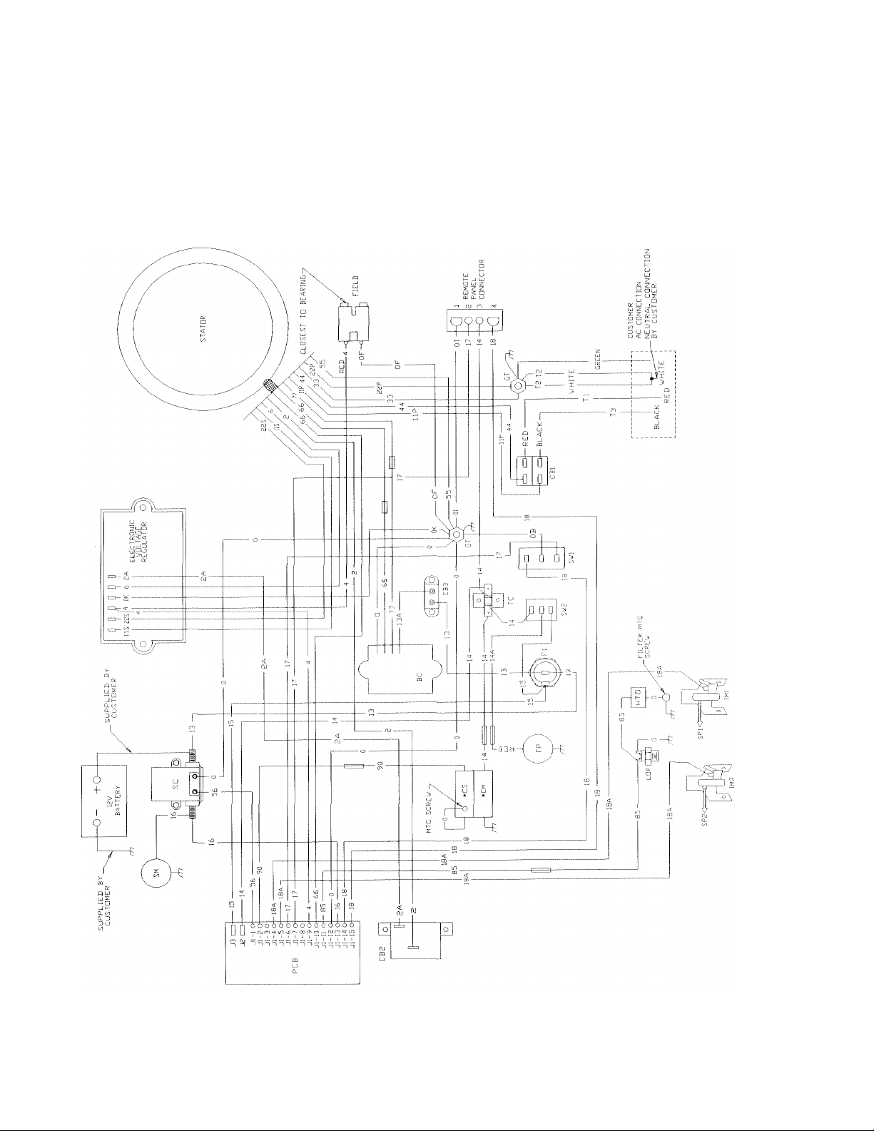
Section 9 — Electrical Data
PRIMEPACT 70G and 70LP Recreational Vehicle Generators
Wiring Diagram - Drawing No. 0D3459
(T)
ELECTRICAL
DATA
Generac* Power Systems, Inc. 33
Page 42

^PARTS
LISTS
Section 10 — Exploded Views and Parts Lists
PRIlVIEPACT 70G and 70LP Recreational Vehicle Generators
Sheet Metal - Drawing No. 0D3465
O"
8
See Carburetor
Exploded View
37 \
40 Generac® Power Systems, Inc.
Page 43

Section 10 — Exploded Views and Parts Lists
PRiWlEPACT 70G and 70LP Recreational Vehicle Generators
Sheet Metal - Drawing No. 0D3465
^PARTS
LISTS
ITEM
1
2 099258 1
3
4 067890
5
6 0A4456
7
8
10
11 074916
12
13
14 078858
15
16
17
19
20
21
22 75246 4
23 0742600133
24 088290 1
25
26 081108
27 022717B
28
29
30 077001
31
33
34 029289
35 087858B
36
37
38
39 033469
40
41 092934 1 REGULATOR-10A.
42
PART NO. QTY. DESCRIPTION
1
067198N
087865
086313
056893 23
087750
074908
073190
078859
074902 2
066476
073191
048571
022129
073186
022717A 2
067866
073132 2
087858A 1
050277
038153
022152 2 NO. 10 LOCK WASHER
023897 2
022158
1
1 HEX NUT
1 PLUG, FLYWHEEL ACCESS
1 3/8" SPECIAL LOCK WASHER
1 HOUSING, ENGINE TOP
1 SCROLL, FLYWHEEL
1 COVER, BASECYL#2
9
1 WRAPPER CYL. #2
1 COVER, VALLEY
1 WRAPPER, CYL #1
4
1 COVER, BASE CYL. #1
2 CAPSCREW, HEX HD.-IV18 x 1.25 x 15MM
2 LOCK WASHER-MS
1 WIRE ASSEMBLY-NO, 16
1 WRAPPER, CRANKCASE
1 BUSHING, SNAP
1
1 O-RING
1 PLUG, OIL FILL
2FT, FOAM TAPE
1 GROUND WIRE ASSEMBLY-CYL. #1
1
2 N0.10-32x1-1/2" SCREW
2
2
SEE ENGINE EXPLODED VIEW of ENGINE
KEY-WOODRUFF 6 x 25MM
BEVELLED WASHER
SCREW (CRIMPTITE) NO. 10-24 x 1/2"
SCREW (TAPTITE) MSxIOMM
WRAPPER, BARREL
HHCS/LW-M6x1,0x12MM
SCREW (TAPTITE) 3/8"-16 x 1-1/4"
STARTER COVER
GROMMET-RUBBER
GROMMET -RUBBER
BOOT SPARK PLUG
GROUND WIRE ASEMBLY-CYL. #2
OIL DRAIN DECAL
0.22 INCH I.D. SPACER
NO. 10 FLAT WASHER
NO. 10-32 HEX NUT
Generac* Power Systems, Inc. 4T
Page 44

^PARTS
id),
LISTS
Section 10 — Exploded Views and Parts Lists
PRIMEPACT 70G and 70LP Recreational Vehicle Generators
Base and Pulleys - Drawing No. 0D3464A
42 Generac* Power Systems, Inc.
Page 45

Section 10 — Exploded Views and Parts Lists
PRIMEPACT 70G and 70LP Recreational Vehicle Generators
Base and Pulleys - Drawing No. 0D3464A
FEM PART NO. QTY. DESCRIPTION
1
086318
2 022145
046911
3
4 025017 8 CAPSCREW, HEX HD.-3/8"-6 x 1/2"
5 022237 6
6 022129 8 LOCKWASHER5/16" -M8
7 072391 2
077603 2
8
9 022259
052858 6 NUT FLANGED LOCK-M8-1.25
10
11 051730
12 029459 2
13 075215
14 073146
15 075209
073174
16
17 079678
18 040976
072383
19
023897 6
20
21 075224-G
22 073106-G 1
075216
23
24 049451
25 042633
26 077017
27 073118 1
28 074906
022152
29
30 072375
31 073185
022097 6 LOCKWASHER
32
077682 1
33
34 075242
049813 2
35
36 045757
37
090859
048031-E 2 CLAMP, HOSE-3/8"
38
39 091123
40 045756
41 081105
087768
42
07571OA 1 TUBE, OIL FILL AND DRAIN
43
44 074958
067871 1 O-RING, CAP
45
46 0A5508
47
075711
48 022413
0A5802 1 TINNERMAN CLIP
49
1 BASE, MOUNTING
4 FLAT WASHER 5/16" -M8
4
MOUNT, (RUBBER)
LOCKWASHER-3/8"
SKID, RUBBER MOUNT 56 073179
SAFETY BOLT, 5/16"-18x 3-1/2" 57 070185
2 NUT, HEX -5/16--18
2 CAPSCR, HEX HD.-M8-1.25 x 60mm
SPRING, BELT TENSION 61
2 WASHER, SPRING CNTR,
4
SLIDE (NYLON)
2 SUPPORT, NYLON SLIDE
1 MANIFOLD, EXHAUST
2 RING, SEALING
4 SHCS, M8-1,25 x 20mm
2 GASKET, COLLECTOR PAN
FLAT WASHER #10-M5 68 087770
1 PULLEY, ENGINE
PULLEY, ALTERNATOR
1 BELT (POLY V 4L)-40”
1 WASHER, PULLEY RETAINER
7GA, ,41"x1,62"
1 HHCS, 3/8”-24x1" (GRADES)
1 GUIDE, BLOWER HOUSING
CAPSCR,, HEX HD,-3/8"-24 x 2-1/4"
TAPTITE, M6-1,00x20mm
10
2
WASHER, LOCK #10
1 HOUSING, BLOWER
1 SPACER, BLOWER HOUSING 2-3/8”
'A"
-M6
CAPSCR. HEX HD.-M5-0.80 x 80mm
4 SPRING, GENERATOR SET MT
NUT, HEX M6-1.0 83 022473
2 CAPSCREW, HEX HEAD- M6-1.0 x 25mm
1
COVER PLATE
1 BRACKET, FUEL PUMP
9 TAPTITE, M6-1,0x10mm
5/16-18 FLANGE NUT, SPECIAL 89
2
1 FITTING, 1/8" PIPE TO
1 CAP & DIPSTICK ASSEMBLY
1
OIL FILL TUBE GASKET
1 PIPE, OIL DRAIN ADAPTOR
1
CAPSCR., HEX HD.-1/4-20X1"
'A"
TUBE
ITEM PART NO.
50 043790A 1
51
047290
52 035461 1
53 069811
54 092120 2
087769 1
55
58 0A8584
59
074948
60 074950
074951 1
073134 1
62
63
038750
64
074949
65 068548
66 0C4006
67 029289
075281 1
69
70 OC1085 2
71 043182
72
090088
73 075237
74
0D1624
75 075474
76 090800
77
094670
78 075226
79
056893
80 075229
81 0D3158
82
079246
84
090475
85 072384-C 1
022131 1 FLATWASHER, 3/8" -M10
86
87
077643
88 0A8475
090141 1 GROUND CABLE
90
0A1658
91 045756
92 ODI 227 1 CONTACTOR, STARTER
0133-74260 1
93
94 024414
0D1741A 1 BOOT, BATTERY CABLE
95
96 0D1741 2 BOOT, BATTERY CABLE
97
022158
QTY. DESCRIPTION
ELBOW-3/8" NPT x 3/8"
1 HOSE-3/8" I.D. #6L0LA
FITTING, BARBED-1/4" NPT
1 CAP, HEX-1/4" NPT
NUT LOCK TRIG M6-1.0Y/ZNC
FILTER, FUEL
1 OIL FILTER SUPPORT
FILTER, OIL(FRAM#PH3614)
1
10 PSI-SWITCH, OIL PRESSURE
1
3 FiniNG-5/16"
1 TUBE, OUTER OIL
TUBE, INNER OIL
ADAPTOR, OIL FILTER ADAPTER
CAPSCREW, HEX HEAD
3
M6-1.00 X 30mm
1 FITTING, 90-DEGREE-5/16”
1 GASKET, OIL FILTER ADAPTER
CABLE, BATTERY
1
-
TAPE, FOAM-1/16”THICKx8’
LINE, FUEL
1
SWITCH, HIGH TEMPERATURE
SCREW, PAN HEAD-M3-0.50 x 8mm
2 LOCKWASHER-M3
CLAMP, VINYL COATED
1
4 WASHER, SPRING RETAINER
BOOT, OIL PRESSURE SWITCH
1
BOOT, TEMPERATURE SWITCH
1
1 ELBOW, EXHAUST -UNIVERSAL
CLAMP, EXHAUST
1
1 COVER, AIR
22 CRIMPTITE, NO. 10-24 X 1/2"
GASKET, SLIDE PAN
1
1 SLIDE PAN
CAPSCREW, HEX HEAD
8
M6-1.00X 16mmWITH LOCKWASHER
7 FLATWASHER, H" -M6
! PUMP FUEL
COVER, EXHAUST OUTLET
GASKET, EXHAUST OUTLET
1
SPECIAL LOCKWASHER, M5
1
SPECIAL LOCK WASHER, W"
3
TAPTITE, M6-1.00x10mm
1
CABLE, STARTER
2 HEX NUT, 5/16”-24 STEEL
HEX NUT, #10-32 STEEL
2
Generac® Power Systems, Inc. 43
Page 46

.PARTS
LISTS
Section 10 — Exploded Views and Parts Lists
PRIMEPACT TOG and 70LP Recreational Vehicle Generators
Alternator and Panel - Drawing No. 0D3463
11
28
10 13
22
'J
lA-
fa
VI
40
21
18
12
\
34
38
17
47
17
. TO ENGINE 20
GROUND
24
17
19
13
36
"fV r
44 ' 14/ '"'
45 54 "
35
15
37
43
-J ;■■■
48 44
50
44 45
16
35
57
51
49
31
13
46
29
45
44
<44 Generac* Power Systems, Inc.
0\„
27
26
56
32
I K
31
51
V, 30
0*.
31
30
41
25
33
52,53
23
26
39
/
42
Page 47

Section 10 — Exploded Views and Parts Lists
PRIMEPACT 70G and 70LP Recreational Vehicle Generators
Alternator and Panel - Drawing No. 0D3463
PART NO. QTY. DESCRIPTION ITEM PART NO. QTY. DESCRIPTION
TEM
1
C9675
2
80095H
3 92848H 1
4
73159
31971
5
6 C9674
7
77006
8 52858
9
66386
10 66849
11
27756
12 86314
13
A8475
14
D2724
15 22097 4 '/47 M6-LOCK WASHER 44
1 LOWER BEARING CARRIER 30 75476
1 ROTOR ASSEMBLY
STATOR ASSEMBLY
1 BALL BEARING 33
1
BALL BEARING
1
UPPER BEARING CARRIER 35 75235
4
STUD-STATOR
4 M8-1.25 FLANGE LOCK NUT
1
BRUSH HOLDER 38 49815
2 M5-0.8X 16LG.TAPT1TE 39 43182 2
4 NYLON WASHER 40
1
GENERATOR TOP HOUSING
3 M5-SPECIAL LOCK WASHER 42
2 BOOT, ROCKER SWITCH
22264 6 #8/ M4-LOCK WASHER
31
38077
32
90987 2 M3-0.5X 12LG. PPHMS
86317A 1 PANEL SUPPORT BRACKET
34
82737
36
37
49813 4
45771 4
41 54502
90157
83049
43
22152 6
16 31791 1 CLAMP, HOSE 45 51716
17
90141
18
A1658
19
74906
92234 1
20
21
93846
22
22129
23 23484-S
24
86316A 1
25
53650
C4887 1 SEALTITE CONDUIT ASSEMBLY 54 87798
26
27
75244 1 ASSEMBLY, REMOTE CABLE 55 92113
28 74908
29 23897 1 #10/M5-FLAT WASHER
2
GROUND CABLE 46
1 M6-SPECIAL LOCK WASHER
47
51715
82081
4 M6-1.0X20 LG.TAPTITE 48 25105
CONTROLLER P.C.B.
1 DECAL, CUSTOMER CONN. 50
4
5/167 M8 LOCKWASHER
1
BUSHING
49 86315 1
90734 4
51 22985 3
PANEL SHEET METAL 52 32300 1
1
4-PIN CONNECTOR 53
1 M5-0.8X10LONGTAPTITE 56
22676
75210-A 1
57 A8475-A 1
4
M4-0.7X 16LG. CAPSCREW
1
CIRCUIT BRACKER 15A.
M5-0.8X30 LG. CAPSCREW
4
4 VIBRATION MOUNT
M6-1.0 HEX NUT
1 M5-08X 16LG.HEX HD. CAPSCR.
M3-LOCK WASHER
M8-1.25 HEX NUT
1 C/BREAKER 3.0A
1 DECAL, CB RATING 30A.
1 REGULATOR VOLTAGE
M5-LOCK WASHER
4 M5-0.8 HEX NUT
1 M4-0.7 HEX NUT
C/BREAKER 30A.
1
4 #6-32 X 'A" SCREW W/LOCK WASHER
PANEL COVER
M4-0.7 X 12 LG, CAPSCR.W/LOCK-
WASHERS FLAT WASHER
#6-FLAT WASHER
FUSE HOLDER
FUSE AGC-15A,
1
1 SWITCH S.P.D.T. 6A.-(START-STOP)
SWITCH S.PD.T.-(FUEL PUMP)
1
TERMINAL BLOCK
#8 SPECIAL LOCK WASHER
Generac* Power Systems, Inc. 45
Page 48
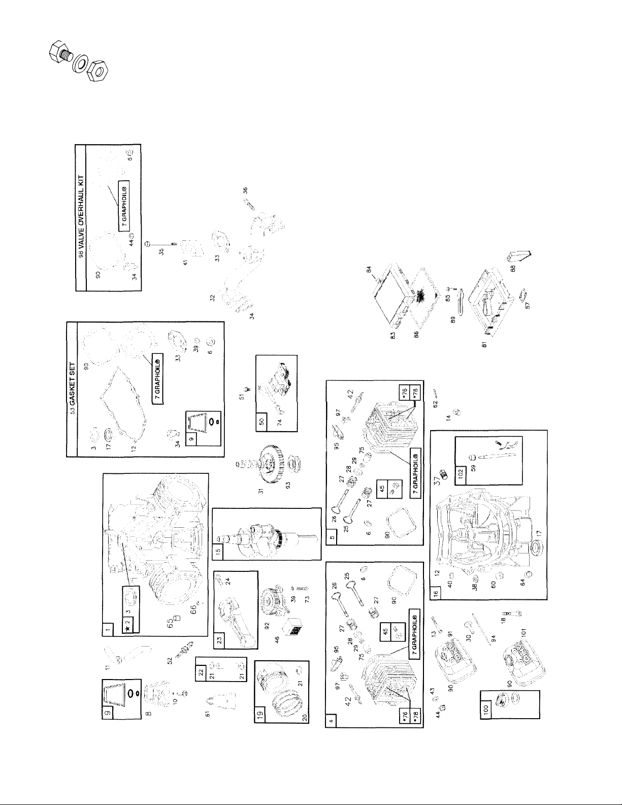
^PARTS
LISTS
Section 10 — Exploded Views and Parts Lists
PRiMEPACT 70G and 70LP Recreational Vehicle Generators
Exploded View - Engine Common Parts - Drawing No. 079216-F
46 Benerac® Power Systems, Inc.
Page 49

Section 10 — Exploded Views and Parts Lists
PRIMEPACT 70G and 70LP Recreational Vehicle Generators
Exploded View - Engine Common Parts - Drawing No. 079216-F
.^PARTS
LISTS
PART NO.
TEM
1
069331 1 CYLINDER ASSEMBLY
*2 069333 1
3
067805
4
079234 1 NO, 1 CYLINDER HEAD ASSEMBLY
5
079235
6 070169
7 069332 2 CYLINDER HEAD GASKET
8 0851100104 1 BREATHER ASSEMBLY
9 072315 1 BREATHER GASKET
10 089967
11 070596
12 069336
13 069325 8 CYLINDER HEAD BOLT
14 067888 2 3/8" NPT OIL DRAIN PLUG
072334 1
15
16 075247 1 OIL SUMP ASSEMBLY 73
17
067924
18 067878 9 OIL SUMP BOLT
19
075248
20 075249 2 STANDARD PISTON RING SET
21 069327 4 PISTON LOCKING RING
22 075250
23 075251 2 CONNECTING ROD ASSEMBLY
24 072346
25 069316 2 EXHAUST VALVE
26 069317 2 INTAKE VALVE 86 069341
27 067816 4
28 069320 4 VALVE SPRING RETAINER 89
29 070513 4
30 070584
31 070530 1 CAMSHAFT ASSEMBLY 92 070547
32 072358 1 INTAKE MANIFOLD 93
33 069379 2 CARBURETOR MOUNTING GASKET 94 070577
34
067895
070594 2 CARBURETOR MOUNTING BOLT 97 070566 4
35
36 067158 4 INTAKE MANIFOLD MOUNTING BOLT
37 068574 1
38
068554A
39 068573
40 070506 1 OIL GALLEY 0-RING
41 070554 1
42 070568 4 ROCKER ARM STUD
43 075253 4
QTY. DESCRIPTION
SLEEVE BEARING
1
OIL SEAL
1 NO, 2 CYLINDER HEAD ASSEMBLY 51
4
SEALING WASHER
1
BREATHER SCREW
1
BREATHER TUBE
1
OIL SUMP GASKET
CRANKSHAFT ASSEMBLY
1 OIL SEAL ASSEMBLY 74
2
STANDARD PISTON ASSEMBLY
2
STANDARD PISTON RING
4
CONNECTING ROD BOLT
VALVE SPRING
VALVE KEEPER
4
VALVE TAPPET
2
INTAKE MANIFOLD GASKET
1/8" NPT PLUG PIPE
1 GOVERNOR SHAFT SEAL 100 091481 1
1
OIL PUMP 0-RING
CARBURETOR SPACER
WASHER VALVE COVER SEAL
ITEM PART NO.
44
067885
45 075254
070535 1
46
47 0C2881
072536
072347 2 SPARK PLUG
52
53 075258
57
066480
59 072361
60 072362 1
070199 1 BREATHER BAFFLE
61
62 072366
64 072365
65 068555
66 067806
068572
075272 2
75 070122
76 067910
78 067813
81 070592 1 AIR CLEANER BASE
82
073123
83 070593
84 0C3633
85 067156
070597 1 AIR INLET TUBE
88
072305
90 067920
91 069328
070536 1 GOVERNOR SLIDER
95 070599
98 075271 1 VALVE OVERHAUL KIT
067897 2 EXHAUST GASKET (NOT SHOWN)
99
101 091480
102 0D1198
'Not Shown
QTY.
DESCRIPTION
4 M6 NYLON NUT
4 VALVE ADJUST SCREW
OIL SCREEN
STARTER MOTOR (NOT SHOWN)
1
4 IGNITION ARMATURE SCREW
1 ENGINE GASKET KIT
1 AIR CLEANER GASKET
1 GOVERNOR SHAFT BUSHING
GOVERNOR SHAFT BUSHING
1 COTTER PIN
GOVERNOR SHAFT WASHER
1
2 CRANKCASE DOWEL
CYLINDER HEAD DOWEL
4
2
OIL PUMP SCREW
SPARK PLUG TERMINAL
4 VALVE STEM SEAL
2 INTAKE VALVE SEAT
4 VALVE GUIDE
1 AIR FILTER (NOT SHOWN)
1 AIR CLEANER COVER
1
AIR CLEANER COVER SCREW
2
AIR CLEANER BASE SCREW
1 FOAM PRE-CLEANER
1
BREATHER DEFLECTOR
2 VALVE COVER GASKET
2 VALVE COVER
1 OIL PUMP ASSEMBLY
4 PUSH ROD
4 ROCKER ARM
ROCKER ARM SUPPORT
GASKET AND CAP ASSEMBLY
1
ROCKER ARM COVER
1
GOVERNOR CRANK
Generac^ Power Systems, Inc. ‘4“7
Page 50
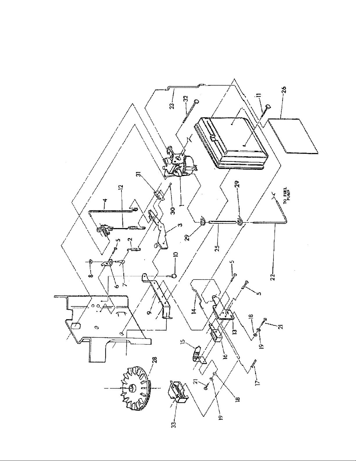
^PARTS
LISTS
Section 10 — Exploded Views and Parts Lists
PRIMEPACT TOG and 70LP Recreational Vehicle Generators
Carburetor - Drawing No. 093753-G
<4S Generac® Power Systems, Inc.
Page 51

Section 10 — Exploded Views and Parts Lists
PRIMEPACT 70G and 70LP Recreational Vehicle Generators
Carburetor - Drawing No. 093753-G
^PARTS
LISTS
ITEM
1
2
PART NO.
073112B 1 Carburetor Assembly
074962C
074962G 1
3
4
5
070155 1
070108 1
056893 5
6 074961 1
7 047227
8
037398
9 073131 1
10
11
12
13
066476
070575
070125
073374 1
14 074947
15 089473 1
16
17
18
091306
077091 1
031879
19 022159 4
*20
21
22
089870
072536
087770
23 074946 1
25
030340
26 0C2338B 1
0C2338 1
091352C
27 075252
28 0A7782A 1
29
30
31
040173
066829
075944 1
32 070594
33 077075
QTY.
1
1
1
2
2
1
1
1
4
1
4
1
1
1
1
2
2
2
1
DESCRIPTION
Spring, Governor (PP55, PP66)
Spring, Governer (Q-70G)
Lever, Governor
Rod, Governor to Carburetor
Screw, (Crimptite) - #10-24 X 1/2”
Bracket, Governor Adjuster
Screw, Governor Adjuster
Nut, Hex Lock (Nylon)
Bracket, Air Cleaner Support
Screw, Hex - M6-1.0 X 12MM
Screw, Hex - M6-1.0 X 25MM
Spring, Anti-Lash
Bracket, Choke Support
Rod, Choke Control
Bi-Metal Assembly, Choke
Solenoid, Choke
Hair Pin, Cotter
Flat Washer - #4
Lock Washer - #4
Solenoid, Fuel Shutoff (Q-70G Only)
Screw, Pan HD. Mach. - #4-40 X 1/4”
Line, Fuel - 5/16” I.D.
Link, Choke
Hose, Fuel, 4.5” LG.
Decal, Air Cleaner Primepact 66G
Decal, Air Cleaner Primepact 55G
Decal, Air Cleaner Q-70G
Kit, Carburetor Overhaul - Not Shown
Flywheel Assembly
Clamp, Hose (Screw Type)
Rivet - 1/8” Diameter X 1/8” Long
Bracket, Governor Spring
Capscrew, Hex HD. - M6-1.0 X 93 LG. w/washer
Cover, Choke Coil
* Not Shown
Cenerac* Power Systems, Inc. 43
Page 52
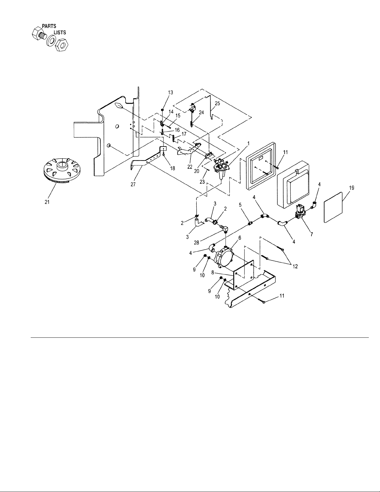
Section 10 — Exploded Views and Parts Lists
PRIMEPACT 70G and 70LP Recreational Vehicle Generators
LP Regulator, LP Carburetor & Air Cleaner - Drawing No. 0A4029-F
ITEM PART NO. QTY.
1 0A1662A
2
057822 2 HOSE CLAMP 074962G 1
3
074994 1
4
026307 4
5 026915
6
075211 1 GASEOUS FUEL REGULATOR 0C2338A 1
7
0A2666 1
1 GARB, V-TWIN L7P
1 3/4" PIPE NIPPLE 0C2338C 1
8 0A5198 1
9 049813
10
022097 4
11 047411
12
038750 2
13 037398
14
074961 1
15
056893
16
047227 1
50 Generac® Power Systems, Inc.
4 M6 HEX NUT 22 070155 1 GOVERNOR LEVER
2 M6-1.0X16MM HEX HD. CAPSCR. 24
1 HEX LOCK NUT (NYLON) +
5 #10-24X1/2" SCREW 27 073131 1 AIR CLEANER SUPPORT BRACKET
DESCRIPTION
1/2" I.D.X 10" LONG HOSE 18
STREET ELBOWS 19 0C2338E
GASEOUS FUEL SOLENOID
REGULATOR MOUNTING BRACKET 21
M6 LOCK WASHER 23 076242 2
M6-1.0 X 30MM HEX HD CAPSCR. 25 070108 1
GOVERNOR ADJUSTER BRACKET
GOVERNOR ADJUSTER SCREW
ITEM PART NO. QTY.
17
20 075944 1 GOVERNOR SPRING BRACKET
+
28 061696 1
074962C
1
066476 2
1
0A7782A
070125
028739
1
1 ANTI-LASH SPRING
4 4" LONG TIE WRAP
055162 9CC
(-^) NOT SHOWN
DESCRIPTION
GOVERNOR SPRING (PP55G/LR PP66G/LP)
GOVERNOR SPRING (PP70G/LR Q70G)
M6-1.0 X 12MM HEX SCREW W/LOCK WASHER
AIR CLEANER DECAL-PRIMEPACT 70LP
AIR CLEANER DECAL-PRIMEPACT 66LP
AIR CLEANER DECAL-PRIMEPACT 55LP
FLYWHEEL ASSEMBLY
1/8" I.D. X 1/8” RIVET
GOVERNOR-TO-CARBURETOR ROD
PIPE SEALANT
BARBED 90 DEG. 3/8" X 1/2"
Page 53

Section 11 — Notes
PRIMEPACT 70G and 70LP Recreational Vehicle Generators
NOTES
Generac* Power Systems, Inc. 51
Page 54

Section 12 - Warranty
PRIMEPACT 70G and 70LP Recreational Vehicle Generators
CALIFORNIA AND FEDERAL EMISSION CONTROL WARRANTY STATEMENT
YOUR WARRANTY RIGHTS AND OBLIGATIONS
Tlic California Air Resources Board (CARB) and the United States Environmental Protection Agency (EPA), together with
Generac Power Systems. Inc. (Cfcnerac). are pleased to explain the Emission Control System Warranty on your new engine.*
New utility, and lawn and garden cciuipment engines must be designed, built and equipped to meet stringent anti-smog stan
dards for the state of California and the federal government. Generac will warrant the emission control system on your
engine for the periods of time listed below provided there has been no abuse, neglect, unapproved modification or improp
er maintenance of your engine.
Your emission control system may include parts such as the carburetor, ignition and exhaust systems. Generac will repair
your engine at no cost to you for diagnosis, replacement parts and labor, should a warrantable condition occur.
MANUFACTURER'S EMISSION CONTROL SYSTEM WARRANTY COVERAGE:
Emissions control systems on 1997 and later model year engines are warranted for two years as hereinafter noted. If, dur
ing such warranty period, any emission-related component or system on your engine is found to be defective in materials or
workmanship, repairs or replacement will be performed by a Generac Authorized Warranty Service Facility.
PURCHASER'S/OWNER'S WARRANTY RESPONSIBILITIES:
As the engine purchaser/owner, you are responsible for the completion of all required maintenance as listed in your factory
supplied Owner’s Manual. For warranty purposes, Generac recommends that you retain all receipts covering maintenance
on your engine. However, Generac cannot deny warranty solely because of the lack of receipts or for your failure to ensure
the completion of all scheduled maintenance.
As the engine purchaser/owner, you should, however, be aware that Generac may deny any and/or all warranty coverage or
responsibility if your engine, or a part/component thereof has failed due to abuse, neglect, improper maintenance or unap
proved modifications, or the use of counterfeit and/or ‘grey market’ parts not made, supplied or approved by Generac.
You are responsible for presenting your engine to a Generac Authorized Warranty Service Facility as soon as a prob
lem occurs. The warranty repairs should be completed in a reasonable amount of time, not to exceed 30 days.
Warranty service can be arranged by contacting either your selling dealer or a Generac Authorized Warranty Service Facility.
To locate the Generac Authorized Warranty Service Facility nearest you, call our toll-free number:
1-800-333-1322
IMPORTANT NOTE: This warranty statement explains your rights and obligations under the Emission Control System
Warranty (ECS Warranty), which is provided to you by Generac pursuant to California and federal law. See also the "Generac
Limited Warranties for Generac Power Systems, Inc.,” which is enclosed herewith on a separate sheet, also provided to you
by Generac. The ECS Warranty applies only to the emission control system of your new engine. If there is any conflict in
terms between the ECS Warranty and the Generac Warranty, the ECS Warranty shall apply except in circumstances where
the Generac Warranty may provide a longer warranty period. Both the ECS Warranty and the Generac Warranty describe
important rights and obligations with respect to your new engine.
Warranty service can be performed only by a Generac Authorized Warranty Service Facility. When requesting warranty ser
vice, evidence must be presented showing the date of the sale to the original purchaser/owner. The purchaser/owner shall
be responsible for any expenses or other charges incurred for service calls and/or transportation of the product to/from the
inspection or repair facilities. The purchaser/owner also shall be responsible for any and/or all damages or losses incurred
while the engine is being transported/shipped for inspection or warranty repairs.
If you have any questions regarding your warranty rights and responsibilities, you should contact Generac at the fol
lowing address:
ATTENTION WARRANTY DEPARTMENT
GENERAC POWER SYSTEMS, INC.
P.O. BOX 297
WHITEWATER, Wl 53190
Part 1
52 Generac® Power Systems, Inc.
Page 55

Section 12 - Warranty
PRIMEPACT 70G and 70LP Recreational Vehicle Generators
EMISSION CONTROL SYSTEM WARRANTY
Emission Control System Warranty (ECS Wai-ranty) for 1997 and later model year engines:
(a) Applicability: This warranty shall apply to 1997 and later model year engines. The ECS Warranty Period shall begin on
the date the new engine or equipment is purchased by/delivered to its original, end-use purchaser/owner and sliall contin
ue for 24 consecutive months thereafter.
(b) General Emissions Warranty Coverage: Generac warrants to the original, end-use purchaser/owner of the new engine or
equipment, and to each subsequent purchaser/owner, that each of its engines is ...
(1) Designed, built and equipped so as to conform with all applicable regulations adopted by the EPA and CARB pursuant
to their respective authority, and
(2) Free from defects in materials and workmanship which, at any time during the ECS Warranty Period, may cause a war
ranted emissions-related part to fail to be identical in all material respects to the part as described in the engine manu
facturer's application for certification,
(c) The ECS Warranty only pertains to emissions-related parts on your engine, as follows:
(1) Any warranted, emissions-related parts that are not scheduled for replacement as required maintenance in the Owner's
Manual shall be warranted for the ECS Warranty Period. If any such part fails during the ECS Warranty Period, it shall
be repaired or replaced by Generac according to Subsection (4) below. Any such part repaired or replaced under the ECS
Warranty shall be warranted for the remainder of the ECS Warranty Period.
(2) Any warranted, emissions-related part that is scheduled only for regular inspection as .specified in the Owner's Manual
shall be warranted for the ECS Warranty Period. A statement in such written instructions to the effect of “repair or replace
as necessary” shall not reduce the ECS Warranty Period. Any such part repaired or replaced under the ECS Warranty
shall be warranted for the remainder of the ECS Warranty Period.
(3) Any warranted, emissions-related part that is scheduled for replacement as required maintenance in the Owner's
Manual shall be warranted for the period of time prior to the first scheduled replacement point for that part. If the part
fails prior to the first scheduled replacement, the part shall be repaired or replaced by Generac according to Subsection
(4) below. Any such emissions-related part repaired or replaced under the ECS Warranty shall be warranted for the
remainder of the ECS Warranty Period prior to the first scheduled replacement point for such emissions-related paid.
(4) Repair or replacement of any warranted, emissions-related part under this ECS Warranty shall be performed at no
charge to the owner at a Generac Authorized Warranty Service Facility,
(5) When the engine is inspected by a Generac Authorized Warranty Service Facility the owner shall not be held responsi
ble for diagnostic costs if the repair is deemed warrantable.
(6) Generac shall be liable for damages to other original engine components or approved modifications proximately caused
by a failure under warranty of any emission-related part covered by the ECS Warranty.
(7) Throughout the ECS Warranty Period, Generac shall maintain a supply of warranted emission-related parts sufficient
to meet the expected demand for such emission-related parts,
(8) Any Generac authorized and approved emission-related replacement part may be used in the performance of any ECS
Warranty maintenance or repairs and will be provided without charge to the purchaser/owner. Such use shall not reduce
Generac's ECS Warranty obligations.
(9) Unapproved, add-on, modified, counterfeit and/or ‘grey market' parts may not be used to modify or repair a Generac
engine. Such use voids this ECS Warranty and shall be sufficient grounds for disallowing an ECS Warranty claim,
Generac shall not be held liable hereunder for failures of any warranted parts of a Generac engine caused by the use of
such an unapproved, add-on, modified, counterfeit and/or ‘grey market' paid.
EMISSION RELATED PARTS INCLUDE THE FOLLOWING:
1) Fuel Metering System:
1.1) Gasoline carburetor assembly and its
internal components (if so equipped).
a) Fuel filter (if so equipped)
b) Carburetor gaskets
c) Fuel pump (if so equipped)
1.2) LPG carburetion assembly and its
internal components (if so equipped).
a) Fuel controller (if so equipped)
b) Mixer and its gaskets (if so equipped)
c) Carburetor and its gaskets (if so equipped)
d) Primary gas regulator (if so equipped)
2) Air Induction System including;
a) Intake pipe/rnanifold
b) Air cleaner
3) Ignition System including:
a) Spark plug
b) Ignition module
4) Catalytic Muffler Assembly (if so equipped) including:
a) Muffler gasket
b) Exhaust manifold
5) Crankcase Breather Assembly including;
a) Breather connection tube
e) LP liquid vaporizer (if so equipped)
‘Generac engine types covered by this warranty statement include the following:
1) Utility
2} Lawn and Garden Equipment
3) Recreational Vehicle (RV) Generator
4) Industrial Mobile (IM) Generator
Part 2
Generac* Power Systems, Inc. 53
Page 56

Section 12 - Warranty
PRIMEPACT 70G and 70LP Recreational Vehicle Generators
GENERAC POWER SYSTEMS' THREE-YEAR LIMITED WARRANTY
FOR RECREATIONAL VEHICLE GENERATORS
NOTE: ALL UNITS MUST BE INSTALLED BY GENERAC POWER SYSTEMS AUTHORIZED SERVICE FACILITIES.
For a i)eriod of 3 (iJirec) years or 2.000 (two tliousand) liours of operation from the date of original sale, wliichever occurs first. Generar
Power Systems, Inc, (Generar) will, at Us option, rejrair or replace any part which, upon examination, inspection and testing by Generac or
:i Generttc Authorized Warranly Service Fticility, is found to be defective under normal use and service, in accordance with the warranty
schedule sel forth below. Any ecjuipment that the purchaser/owner claims to be defective must be returned to and examined by tlie nearest
Generac Antlioi ized Warranty Service Facility. All transportation costs under the warranty, including return to die factory, are to be borne
and prepaid by the purchaser/owner, 'Phis warranty applies only to Generac generators sold and rated for “Recreational Vehicle" (RV) appli
cations, as Generac luis defined Recreational Vehicle generator applications. This warranty is effective only upon Generac’s receipt, from
the original purchaser/owner. of a completed Warranty Regislration Card. This card is the only valid registration identification and must Ire
irresenled at time of request for warranty service. Claims will not be accepted without presentation of the Warranty Registration Card. The
factory recommends exercising the unit one half-hour every season.
WARRANTY SCHEDULE - COMMERCIAL APPLICATIONS
YEAR ONE - 100% (one hundred percent) coverage on part(s), labor, removal and réinstallation listed:
’ Engine - All components
• Alternator - All components
• Transfer System - All components
WARRANTY SCHEDULE - CONSUMER/PERSONAL APPLICATIONS
YEARS ONE AND TWO - 100% (one hundred yrercent) coverage on part(s), labor, removal and reinstallation listed:
• Engine - All components
• Alternator - All components
• Transfer System - All components
YEAR Three - 100% (one hundred percent) only on selected part(s) and labor listed (Any labor and part(s) not listed, and removal and réin
• Rotor, Stator, Conijiuter Control Board, (if applicable with regard to Üie generator) Cylinder Block, Cylinder Head, Crankshaft, Piston(s), Valve,
Valve Lifler(s), Intake and Exliaust Manifolds
The drive train belt and pulleys (if so equipped) on generators used in recreational vehicles shall be warranted against failure due to defec
tive materials or normal usage for tire life of the generator. For the original purchaser/owner. this drive ti'ain warranty shall include part(s)
and labor (removal and reinstallation are not included) plus $50 (fifty dollars - U.S.) payment upon return of the failed belt or pulley by
Die original purcliaser/owner. For subsequent purchaser/owner, this drive train warranly sliall cover belt and pulley part(s) ONLY (labor not
included). Labor, removal and reinstallation is the responsibility of the subsequent purchaser/owier.
Generac RV generators manufactured prior to December 31, 1997. DO NOT have a transferable warranty. Generac RV generators manu
factured after January 1, 1998, have a transferable warranty to tlie second owner ONLY for the remainder of the three-year limited war
ranty. Proof-of-purchase is required and must be presented to a Generac Authorized Warranly Service Facility prior to the performance of
any warranty service.
All warranty expense allowances are subject to the conditions defined in Generac's super se^'^ice information manual.
THIS WARRANTY SHALL NOT APPLY TO THE FOLLOWING;
• Costs of normal maintenance, adjustments, installation and start-up.
• Failures caused by any contaminated fuels or oils.
• Failures due, but not limited, to normal wear and tear, accident, misuse, abuse, negligence or improper installation. As wiUi all
mechanical devices, the GN-Series engines need periodic part(s) service and replacement to perform well. This warranty will not cover
repair when normal use has exhausted the life of a part(s) or engine.
“ Failures caused by any external cause or act of God, such as collision, theft, vandalism, riot or wars, nuclear holocaust, fire, freezing,
lightning, earthquake, windstorm, hail, volcanic eruption, water or flood, tornado or hurricane,
• Products tliat are modified or altered in a manner not authorized by Generac in writing,
• Any' incidental, consequential or indirect damages caused by defects in materials or workmanship, or any delay in repair or replace
ment of die defective part(s),
• Failure due to misapplication.
• Teleplione, telegraph, teletype or other communication expenses.
• Living or travel expenses of person(s) performing service, except as specifically included within tlie terms of a specific unit warranty period.
• Rental equipment used while warranty repairs are being performed.
• Overnight freight costs for replacement parfls).
• Overtime labor.
• Starting batteries, fuses, light bulbs and engine fluids.
i'HIS WARRANTY IS IN PLACE OF ALL OTHER WARRANTIES, EXPRESSED OR IMPLIED, SPECIFICALLY, GENERAC MAKES NO OTHER
WARI/ANTIES AS TO THE MERCHANI'ABILITY OR FITNESS FOR A PARTICULAR PURPOSE, -Some states do not allow limitations on how
long an implied warranty lasts, so the above limitation may not apply to you.
GENERAC'S ONLY LIABILITY SHALL BE THE REPAIR OR REPLACEMENT OF PART(S) AS STATED ABOVE, IN NO EVENT SHALL GEN
ERAC BE LIABLE FOR ANY INCIDENTAL OR CONSEQUENTIAL DAMAGES, EVEN IF SUCH DAIMAGES ARE A DIRECT RESULT OF GEN
ERAC'S NEGLIGENCE. Some states do not allow the exclusion or limitation of incidental or consequential damages, so Uie above limita
tion may not apply to you. Purchaser/owner agrees to make no claims against Generac based on negligence.
This warranty gives you specific legal rights. You also may have other rights that vary from state to state.
Part No. CSBO-l
stallation are the owner's responsibility):
FOR THE LIFE OF THE RECREATIONAL VEHICLE GENERATOR (IF SO EQUIPPED)
GEMERAC®
P.O.
BOX
POWER SYSTEMS, INC.
S • WAUKESHA, Wi
Revision O (04/16/01) Printed in U.S.A.
531 S7
 Loading...