

Page 1
Series
®
Guardian®
Series
INCLUDES:
• Two Line LCD Tri-Lingual Digital Nexus™
Controller
• Isochronous Electronic Governor
• Sound Attenuated Enclosure
• Closed Coolant Recovery System
• Smart Battery Charger
• UV/Ozone Resistant Hoses
• ±1% Voltage Regulation
• Natural Gas or LP Operation*
• 2 Year Limited Warranty
®
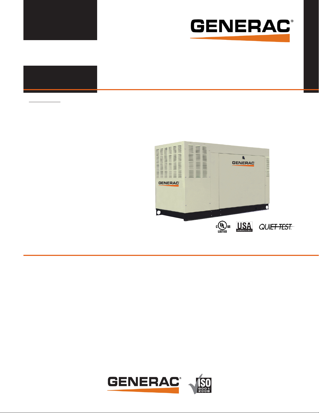
GUARDIAN
SERIES
Standby Generators
Liquid-Cooled Gas Engine
Standby Power Rating
Model QT025 (Steel - Bisque) - 25 kW 60Hz
Model QT030 (Steel - Bisque) - 30 kW 60Hz
Model QT045 (Steel - Bisque) - 45 kW 60Hz
Model QT060 (Steel - Bisque or Aluminum - Gray) - 60 kW 60Hz
Guardian
1 of 9
• UL 2200 Listed
* Note: 25-45 kW units are field convertible between
natural gas or LP. 60 kW units are built per fuel
requirement and are not convertible.
FEATURES
¡ INNOVATIVE DESIGN & PROTOTYPE TESTING are key components of
GENERAC’S success in “IMPROVING POWER BY DESIGN.” But it
doesn’t stop there. Total commitment to component testing, reliability
testing, environmental testing, destruction and life testing, plus testing
to applicable CSA, NEMA, EGSA, and other standards, allows you to
choose GENERAC POWER SYSTEMS with the confidence that these
systems will provide superior performance.
¡ TEST CRITERIA:
PROTOTYPE TESTED NEMA MG1-22 EVALUATION
SYSTEM TORSIONAL TESTED MOTOR STARTING ABILITY
Meets EPA Emission Regulations
25, 30 & 45 kW CA/MA emissions compliant
60 kW not for sale in CA/MA
¡ SOLID-STATE, FREQUENCY COMPENSATED VOLTAGE REGULATION.
This state-of-the-art power maximizing regulation system is standard on
all Generac models. It provides optimized FAST RESPONSE to changing
load conditions and MAXIMUM MOTOR STARTING CAPABILITY by
electronically torque-matching the surge loads to the engine. Digital
voltage regulation at ±1%.
¡ SINGLE SOURCE SERVICE RESPONSE from Generac’s extensive dealer
network provides parts and service know-how for the entire unit, from the
engine to the smallest electronic component.
¡ GENERAC TRANSFER SWITCHES. Long life and reliability are
synonymous with GENERAC POWER SYSTEMS. One reason for this
confidence is that the GENERAC product line includes its own transfer
systems and controls for total system compatibility.
Page 2
Series
25 • 30 • 45 • 60 kW application & engineering data
®
Guardian
2 of 9
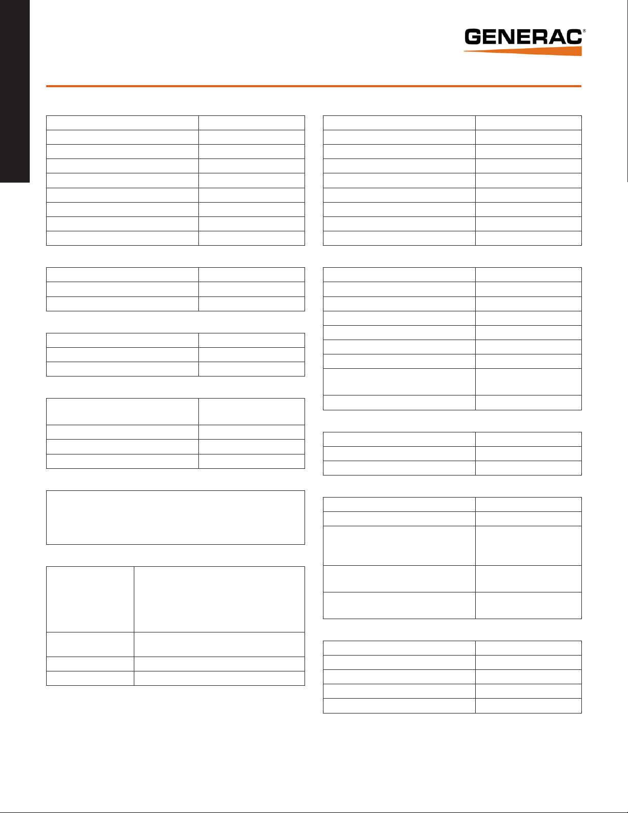
GENERATOR SPECIFICATIONS
Type Synchronous
Rotor Insulation Class H
Stator Insulation Class H
Telephone Interference Factor (TIF) <50
Alternator Output Leads 1-Phase 4 wire
Alternator Output Leads 3-Phase 6 wire
Bearings Sealed Ball
Coupling Flexible Disc
Excitation System Direct
VOLTAGE REGULATION
Type Electronic
Sensing Single Phase
Regulation ± 1%
GOVERNOR SPECIFICATIONS
Type Electronic
Frequency Regulation Isochronous
Steady State Regulation ± 0.25%
ELECTRICAL SYSTEM
Battery Charge Alternator
Static Battery Charger 2 Amp
Recommended Battery Group 26, 525CCA
System Voltage 12 Volts
12 Volt 15 Amp-25 & 30 kW
12 Volt 30 Amp-45 & 60 kW
GENERATOR FEATURES
Revolving field heavy duty generator
Directly connected to the engine
Operating temperature rise 120 °C above a 40 °C ambient
Class H insulation is rated at 150 °C rise at 25 °C ambient
All models fully prototyped tested
ENCLOSURE FEATURES
Steel weather protective
enclosure with aluminum
roof (all models) or
aluminum weather
protective enclosure
(available on 60 kW only)
Enclosed critical grade
muffler
Small, compact, attractive Makes for an easy, eye appealing installation.
SAE Sound attenuated enclosure ensures quiet operation.
Ensures protection against mother nature.
Electrostatically applied textured epoxy paint for added
durability.
Quiet, critical grade muffler is mounted inside the unit
to prevent injuries.
ENGINE SPECIFICATIONS: 25 & 30kW
Make Generac
Model In-line
Cylinders 4
Displacement (Liters) 1.5
Bore (in./mm) 3.05/77.4
Stroke (in./mm) 3.13/79.5
Compression Ratio 11:1
Intake Air System Naturally Aspirated
Lifter Type Hydraulic
ENGINE SPECIFICATIONS: 45 & 60kW
Make Generac
Model In-line
Cylinders 4
Displacement (Liters) 2.4
Bore (in/mm) 3.41/86.5
Stroke (in/mm) 3.94/100
Compression Ratio 9.5:1
Intake Air System
Lifter Type Hydraulic
Naturally Aspirated (45 kW) or
Turbocharged/Aftercooled (60 kW)
ENGINE LUBRICATION SYSTEM
Oil Pump Type Gear
Oil Filter Type Full flow spin-on cartridge
Crankcase Capacity (quarts/liters) 4/3.8
ENGINE COOLING SYSTEM
Type Closed
Water Pump Belt driven
2484 - 25 & 30 kW
Fan Speed (rpm)
Fan Diameter (in/mm)
Fan Mode
17.7/449.6 (25 & 30 kW) or
1865 - 45 kW
2100 - 60 kW
22/558.8 (45 & 60 kW)
Pusher (25 & 30 kW) or
Puller (45 & 60 kW)
FUEL SYSTEM
Fuel Type Natural gas, propane vapor
Carburetor Down Draft
Secondary Fuel Regulator Standard
Fuel Shut Off Solenoid Standard
Operating Fuel Pressure 5” - 14” H2O
(All ratings in accordance with BS5514, ISO3046, ISO8528, SAE J1349 and DIN6271)
Page 3
25 • 30 • 45 • 60 kW operating data
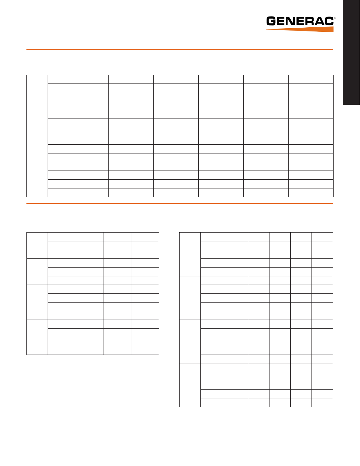
GENERATOR OUTPUT VOLTAGE/kW - 60Hz
kW LPG Amp LPG kW Nat. Gas Amp Nat. Gas CB Size (Both)
120/240 V, 1Ø, 1.0 pf 25 104 25 104 125
QT025
QT030
QT045
QT060
120/208 V, 3Ø, 0.8 pf 25 87 25 87 100
120/240 V, 3Ø, 0.8 pf 25 75 25 75 90
120/240 V, 1Ø, 1.0 pf 30 125 30 125 150
120/208 V, 3Ø, 0.8 pf 30 104 30 104 125
120/240 V, 3Ø, 0.8 pf 30 90 30 90 100
120/240 V, 1Ø, 1.0 pf 45 188 45 188 200
120/208 V, 3Ø, 0.8 pf 45 156 45 156 175
120/240 V, 3Ø, 0.8 pf 45 135 45 135 150
277/480 V, 3Ø, 0.8 pf 45 68 45 68 80
120/240 V, 1Ø, 1.0 pf 60 250 60 250 300
120/208 V, 3Ø, 0.8 pf 60 208 60 208 250
120/240 V, 3Ø, 0.8 pf 60 180 60 180 200
277/480 V, 3Ø, 0.8 pf 60 90 60 90 100
Series
®
Guardian
3 of 9
SURGE CAPACITY IN AMPS
Voltage Dip @ < .4 pf
15% 30%
120/240 V, 1Ø 86 209
QT025
QT030
QT045
QT060
Note: Fuel pipe must be sized for full load.
For Btu content, multiply ft3/hr x 2520 (LP) or ft3/hr x 1000 (NG)
For megajoule content, multiple m³/hr x 93.89 (LP) or m³/hr x 37.26 (NG)
Refer to "Emissions Data Sheets" for maximum fuel flow for EPA and SCAQMD permitting purposes.
120/208 V, 3Ø 84 204
120/240 V, 3Ø 73 177
120/240 V, 1Ø 109 264
120/208 V, 3Ø 109 264
120/240 V, 3Ø 94 229
120/240 V, 1Ø 61 153
120/208 V, 3Ø 64 160
120/240 V, 3Ø 55 139
277/480 V, 3Ø 29 72
120/240 V, 1Ø 95 237
120/208 V, 3Ø 100 251
120/240 V, 3Ø 87 218
277/480 V, 3Ø 42 105
ENGINE FUEL CONSUMPTION
QT025
QT030
QT045
QT060
Natural Gas Propane
(ft³/hr) (m³ /hr) (gal/hr) (l/hr)
Exercise cycle 60 1.7 0.7 2.5
25% of rated load 220 6.3 2.9 9.1
50% of rated load 297 8.4 3.3 12.3
75% of rated load 362 10.3 4 15
100% of rated load 430 12.2 4.7 17.8
Exercise cycle 60 1.7 0.7 2.5
25% of rated load 240 6.8 2.6 10
50% of rated load 320 9.1 3.5 13.3
75% of rated load 400 11.4 4.4 16.6
100% of rated load 492 14 5.4 20.4
Exercise cycle 65 1.8 0.7 2.6
25% of rated load 210 6 2.3 8.6
50% of rated load 380 10.8 4.2 15.7
75% of rated load 545 15.5 5.9 22.4
100% of rated load 730 20.7 8 30.1
Exercise cycle 123 3.5 1.34 5.1
25% of rated load 267 7.6 2.7 10.5
50% of rated load 483 13.7 5 19
75% of rated load 672 19.1 7 26.5
100% of rated load 862 24.5 9 33.9
STANDBY RATING: Standby ratings apply to installations served by a reliable utility source. The standby rating is applicable to varying loads for the duration of a power outage. There
is no overload capability for this rating. Ratings are in accordance with ISO-3046-1. Design and specifications are subject to change without notice.
Page 4

Series
25 • 30 • 45 • 60 kW operating data
®
ENGINE COOLING
Guardian
4 of 9
25 kW 30 kW 45 kW 60 kW
Air flow (inlet air including alternator and combustion air in cfm/cmm) 2490/70.5 2490/70.5 2725/77.2 3280/92.9
System coolant capacity (gal/liters) 2/7.6 2/7.6 3/11.4 2.5/9.5
Heat rejection to coolant (BTU per hr/MJ per hr) 112,000/118.2 135,000/142.4 193,000/203.6 270,000/284.9
Maximum operation air temperature on radiator (°C/°F) 60/150
Maximum ambient temperature (°C/°F) 50/140
COMBUSTION REQUIREMENTS
Flow at rated power (cfm/cmm) 62/1.8 72/2 144/4.1 180/5.1
SOUND EMISSIONS
Sound output in dB(A) at 23 ft (7 m) with generator in exercise mode* 59 59 61 65
Sound output in dB(A) at 23 ft (7 m) with generator operating at normal load* 72 73 73 72
*Sound levels are taken from the front of the generator. Sound levels taken from other sides of the generator may be higher depending on installation parameters.
EXHAUST
Exhaust flow at rated output (cfm/cmm) 203/5.7 237/6.7 420/11.9 494/14
Exhaust temperature at muffler outlet (°C/°F) 593/1100 610/1130 593/1100 566/1050
ENGINE PARAMETERS
Rated Synchronous rpm 3600
POWER ADJUSTMENT FOR AMBIENT CONDITIONS
Temperature Deration ...........................................................................................................3% for every 10 °C above 25 °C or 1.65% for every 10 °F above 77 °F
Altitude Deration (25, 30 & 45 kW) .....................................................................................1% for every 100 m above 183 m or 3% for every 1000 ft above 600 ft
Altitude Deration (60 kW) ................................................................................................ 1% for every 100 m above 915 m or 3% for every 1000 ft above 3000 ft
CONTROLLER FEATURES
2-Line Plain Text LCD Display ........................................................................................................................................Simple user interface for ease of operation.
Mode Switch: Auto ..............................................................................................................................................Automatic Start on Utility failure. 7 day exerciser
Off ...........................................................................................................................Stops unit. Power is removed. Control and charger still operate.
Manual ......................................................................................... Start with starter control, unit stays on. If utility fails, transfer to load takes place.
Programmable start delay between 10-30 seconds ............................................................................................................................................................ Standard
Engine Start Sequence ..................................................................................................................... Cyclic cranking: 16 sec on, 7 rest (90 sec maximum duration)
Engine Warm-up ..................................................................................................................................................................................................................... 5 sec
Engine Cool-Down ..................................................................................................................................................................................................................1 min
Starter Lock-out ................................................................................................................................Starter cannot re-engage until 5 sec after engine has stopped.
Smart Battery Charger ........................................................................................................................................................................................................ Standard
Automatic Voltage Regulation with Over and Under Voltage Protection ................................................................................................................................ Standard
Automatic Low Oil Pressure Shutdown ............................................................................................................................................................................... Standard
Overspeed Shutdown .............................................................................................................................................................................................. Standard, 72 Hz
High Temperature Shutdown ............................................................................................................................................................................................... Standard
Overcrank Protection ..........................................................................................................................................................................................................Standard
Safety Fused ...................................................................................................................................................................................................................... Standard
Failure to Transfer Protection .............................................................................................................................................................................................. Standard
Low Battery Protection ........................................................................................................................................................................................................ Standard
50 Event Run Log ...............................................................................................................................................................................................................Standard
Future Set Capable Exerciser .............................................................................................................................................................................................. Standard
Incorrect Wiring Protection ................................................................................................................................................................................................. Standard
Internal Fault Protection .....................................................................................................................................................................................................Standard
Common External Fault Capability ...................................................................................................................................................................................... Standard
Governor Failure Protection ................................................................................................................................................................................................ Standard
Page 5

25 • 30 • 45 • 60 kW available accessories
Model # Product Description
Series
®
006175-0 - 25 & 30 kW
005630-0 - 45 & 60 kW
006174-0 - 25 & 30 kW
005616-0 - 45 & 60 kW
005621-0
005651-0 Base Plug Kit Add base plugs to the base of the generator to keep out debris.
005703-0 - Bisque
005704-0 - Gray
006176-0 - 25 & 30 kW
006172-0 - 45 kW
006171-0 - 60 kW
005928-0 Wireless Remote
Cold Weather Kit
Extreme Cold Weather Kit
Auxiliary Transfer Switch
Contact Kit
Paint Kit*
Scheduled Maintenance Kit
If the temperature regularly falls below 32 °F (0 °C), install a cold weather kit
to maintain optimal battery temperature. Kit consists of battery warmer with
thermostat built into the wrap.
Recommended where the temperature regularly falls below 32 °F (0 °C) for
extended periods of time. For liquid cooled units only.
The auxiliary transfer switch contact kit allows the transfer switch to lock out
a single large electrical load you may not need. Not compatible with 60kW
models.
If the generator enclosure is scratched or damaged, it is important to touch-up
the paint to protect from future corrosion. The paint kit includes the necessary
paint to properly maintain or touch-up a generator enclosure.
The Liquid-Cooled Scheduled Maintenance Kits offer all the hardware necessary
to perform complete maintenance on Generac liquid-cooled generators.
Completely wireless and battery powered, Generac's wireless remote monitor
provides you with instant status information without ever leaving the house.
Guardian
5 of 9
Remotely control generator functions with the advanced model’s LCD display.
005951-0 Advanced Wireless Remote
006199-0 PMM Starter Kit
006186-0
006463-0 Mobile Link™
006478-0 Harness Adapter Kit
* Note: Bisque kits are used in conjunction with steel enclosures. Gray kits are used in conjunction with aluminum enclosures (available on 60kW units only).
Power Management
Module (50 Amps)
In addition to remote testing of the generator, set the exercise cycle and
maintenance interval reminders.
The PMM Starter Kit consists of a 24 VAC, field installed transformer that
enables the use of the 24 VAC Power Management Modules (PMMs) and one
PMM. The standard controller (without starter kit) can control two HVAC loads
with no additional hardware. Not compatible with pre-wired switches.
Power Management Modules are used in conjunction with the Smart Switch
to increase its power management capabilities. It gives the Smart Switch
additional power management flexibility not found in any other transfer switch.
Not compatible with pre-wired switches. Note: PMM Starter Kit required.
Generac's Mobile Link allows you to check the status of your generator from
anywhere that you have access to an Internet connection from a PC or with any
smart device. You will even be notified when a change in the generator’s status
occurs via e-mail or text message. Note: Harness Adapter Kit required.
The Harness Adapter Kit is required to make liquid-cooled units compatible with
Mobile Link™.
Page 6

Series
25 • 30 • 45 • 60 kW interconnections
®
Guardian
6 of 9
RTS TRANSFER SWITCH
0 GROUND
T1
15B +12V
23 TRANSFER
N2
N1
NEUTRAL
CONTACTOR1CONTACTOR2CONTACTOR3CONTACTOR
AIR 1
AIR 2
UTILITY
(C1 & VR1)
4
PRIORITY 1
PRIORITY 2
PRIORITY 3
PRIORITY 4
LOAD SHED
N1 N2
MODULE
48850-T
E2E1
T1 T2
STANDBY
(C2 & VR2)
0
23
194
+12VDC
TRANSFER
DC COMMON
CUSTOMER CONNECTIONS
0
23
194
T1
N2N1
WARNING
NOTE WIRE ORIENTATION
T2
E2
E1
T1
CENTER
PROTECTED LOAD
NEUTRAL BLOCK
GROUND
CUSTOMER SUPPLIED
NEUTRAL WIRE
FEEDER SUPPLY FROM PANEL
(REQUIRES 4-WIRE FEEDER)
ON
NEU
T1/LINE
N2
CONNECTION PANEL
N1
LIQUID-COOLED GENERATOR
A TYPICAL RESIDENTIAL/COMMERCIAL
T1
N2
N1
NEUTRAL BLOCK
178
183
23
194
E1 E2
NEUT
0
23
194
GROUND
LIQUID COOLED INSTALLATION
Note: Use the generator's specific installation manual
and wiring diagrams to verify generator wiring
connections, as they may differ slightly from illustration.
NOTE:
MATCH WIRE
NUMBERS TO
TERMINAL NUMBERS
Page 7

25 & 30 kW installation layout
Series
®
Guardian
7 of 9
Page 8
Series
®
Guardian
8 of 9
45 kW installation layout
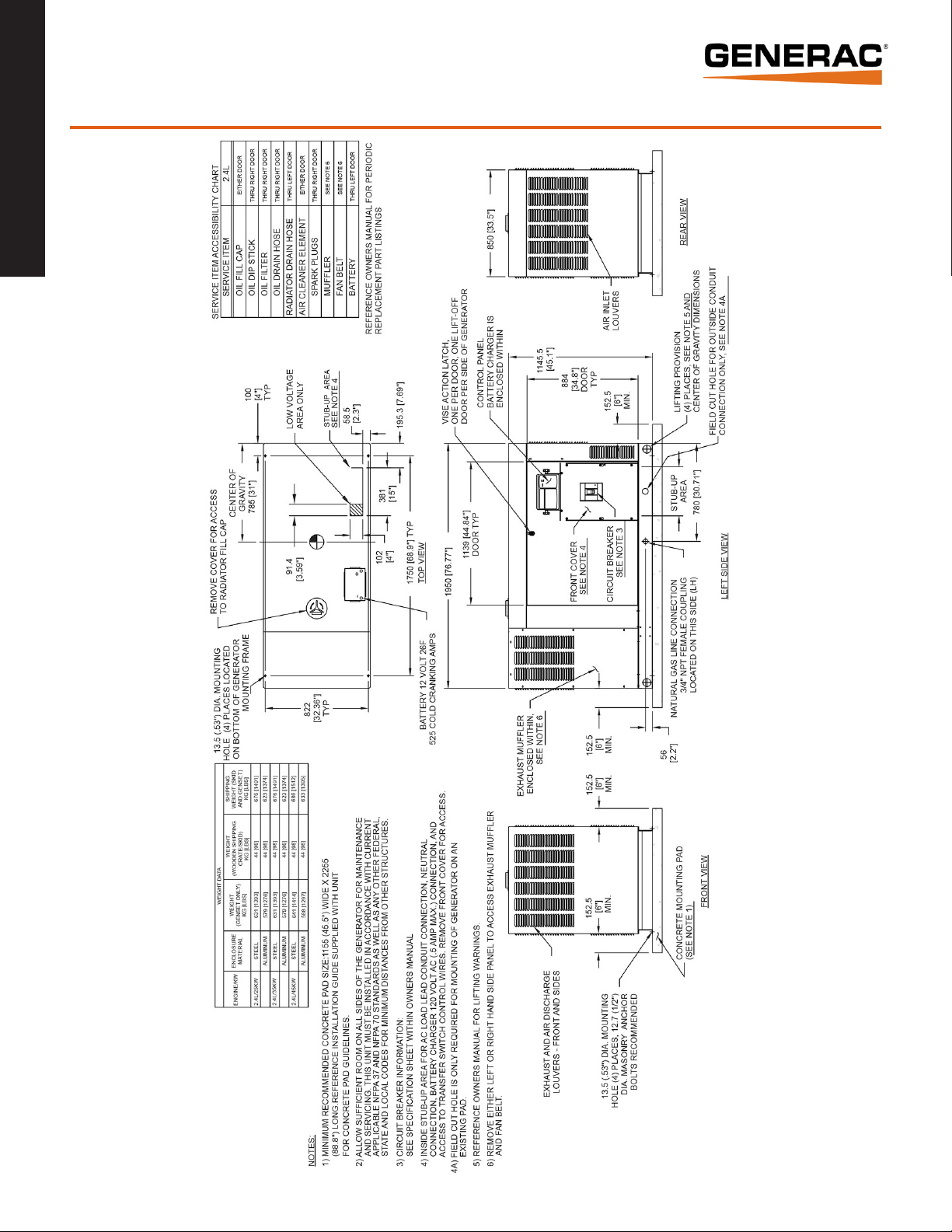
Page 9

60 kW installation layout
Series
®
Guardian
9 of 9
Generac Power Systems, Inc. • S45 W29290 HWY. 59, Waukesha, WI 53189 • generac.com
©2013 Generac Power Systems, Inc. All rights reserved. All specifications are subject to change without notice. Bulletin 0199380SBY-B Printed in U.S.A. 07/30/13
 Loading...