

Generac GP6500E-5941-0, GP6500-5940-0, 5940-0, 005941-0, 005939-0 Owner’s Manual
r|Owne s IVlanual
G ®
- •
GPSeriesPortableGefl
br
introduction.............................................................1
ReadthisiVlanualThoroughly.................................1
Safety Rules ...........................................................1
StandardsIndex.............................................................3
Generalinformation................................................4
1.1 Unpacking......................................................................4
1.1.1 Accessory Box..................................................4
1.2 Assembly.......................................................................4
1.2.1 Assemblingthe Accessory Kit............................4
1.2.2 StarterConnection(ElectricStart Only)..............4
Operation................................................................4
2.1 Knowthe Generator.......................................................4
2.2 Hourmeter......................................................................5
2.3 CordSets andConnectionPlugs....................................6
2.3.1 120 VAC,20 Amp, DuplexReceptacle...............6
2.3.2 120/240 VAC,30 Amp, Receptacle....................6
2.4 Howto Usethe Generator..............................................6
2.4.1 Groundingthe Generator....................................6
2.4.2 ConnectingElectricalLoads...............................7
2.5 Don'tOverloadthe Generator..........................................7
2.6 WattageReferenceGuide...............................................7
2.7 BeforeStartingtheGenerator.........................................8
2.7.1 AddingEngineOil..............................................8
2.7.2 AddingGasoline.................................................8
2.8 Starting Pull Start Engines..............................................8
2.9 Starting ElectricStart Engines........................................9
2.10 Stoppingthe Engine.....................................................10
2.11 LowOil LevelShutdownSystem..................................10
2.11.1 SensingLow Oil Level......................................10
2.12 Chargingthe Battery(Electric Start UnitsOnly).............10
Maintenance.........................................................10
3.1 MaintenanceSchedule.................................................10
3.2 ProductSpecifications..................................................10
3.2.1 GeneratorSpecifications..................................10
3.2.2 EngineSpecifications.......................................11
3.2.3 EmissionsInformation.....................................11
3.3 GeneralRecommendations...........................................11
3.3.1 GeneratorMaintenance....................................11
3.3.2 ToCleanthe Generator.....................................11
3.3.3 EngineMaintenance......................................... 11
3.3.4 CheckingOil Level...........................................11
3.3.5 Changingthe Oil..............................................11
3.3.6 Replacingthe SparkPlug.................................12
3.3.7 Battery Replacement........................................12
3.4 ServiceAir Filter...........................................................12
3.5 ValveClearance............................................................13
3.6 General........................................................................13
3.7 Long TermStorage....................................................... 13
3.8 OtherStorageTips.......................................................13
Troubleshooting....................................................14
4.1 TroubleshootingGuide..................................................14
Notes....................................................................15
Warranty...............................................................16
Manualdel propietario.............................19
Manueld'entretien....................................39
iNTRODUCTiON
Thankyou for purchasingthis model by GeneracPowerSystems,
Inc. This model is a compact, high performance, air-cooled,
engine driven generatordesigned to supply electrical power to
operateelectrical loads where no utility power is availableor in
placeof utility dueto apoweroutage.
BEADTHiSMANUALTHOROUGHLY
If any portion of this manual is not understood, contact the
nearest Authorized Dealerfor starting, operating and servicing
procedures.
The operator is responsible for proper and safe use of the
equipment.We strongly recommend that the operator read this
manualandthoroughlyunderstandall instructionsbeforeusingthe
equipment.Wealsostronglyrecommendinstructingother usersto
properlystart andoperatethe unit.This preparesthem ifthey need
to operatetheequipmentin an emergency.
Thegeneratorcan operate safely,efficiently and reliably only if it
is properly located,operatedand maintained.Beforeoperatingor
servicingthe generator:
• Becomefamiliar with and strictly adhereto all local, state and
nationalcodes and regulations.
• Study all safety warnings in this manual and on the product
carefully.
• Becomefamiliarwith this manualandthe unit beforeuse.
Themanufacturercannot anticipateevery possible circumstance
that might involvea hazard.Thewarnings in this manual,and on
tags and decals affixedto the unit are,therefore,not all inclusive.
If usinga procedure,work method or operatingtechniquethat the
manufacturerdoes not specifically recommend,ensure that it is
safe for others. Also make sure the procedure,work methodor
operatingtechniqueutilizeddoes not renderthe generatorunsafe.
THE INFORMATIONCONTAINEDHEREIN WAS BASED ON
MACHINESIN PRODUCTIONAT THE TIME OF PUBLICATION.
GENERACRESERVESTHERIGHTTOMODIFYTHISMANUALAT
ANYTIME.
SAFETYRULES
Throughoutthis publication,and on tags and decals affixedto the
generator,DANGER,WARNING,CAUTIONand NOTEblocks are
usedto alert personnelto special instructions about a particular
operation that may be hazardous if performed incorrectly or
carelessly.Observethemcarefully.Theirdefinitionsareasfollows:
INDICATES A HAZARDOUS SITUATION OR ACTION
WHICH, iF NOT AVOIDED, WILL RESULT iN DEATH
OR SERIOUS INJURY.
Indicates a hazardous situation or action which, if
not avoided, could result in death or serious injury.
,ACAUTION!
Indicates a hazardous situation or action which,
if not avoided, could result in minor or moderate
injury.
NOTE:
Notes containadditional informationimportantto a procedure
and will be found withinthe regulartextbody of thismanual.
These safety warnings cannot eliminate the hazards that they
indicate. Common sense and strict compliancewith the special
instructionswhileperforming theaction or serviceareessentialto
preventingaccidents.
Four commonly used safety symbols accompany the BANGER,
WARNINGand CAUTIONblocks. The type of information each
indicatesis asfollows:
,_This symbol points out important safety
information that, if not followed, could
endanger personal safety and/or property of
others.
This symbol points out potential explosion
hazard.
//_This symbol points out potential fire hazard.
This symbol points out potential electrical
shock hazard.
GENERAL HAZARDS
• NEVERoperatein an enclosed area, in a vehicle, or indoors
EVENIFdoors and windows areopen.
• For safety reasons, the manufacturer recommends that the
maintenanceof this equipmentis carried out by an Authorized
Dealer.Inspectthe generatorregularly,and contactthe nearest
AuthorizedDealerfor parts needingrepairor replacement.
• Operategeneratoronly on levelsurfacesandwhereit will notbe
exposedto excessivemoisture,dirt, dust or corrosive vapors.
• Keephands, feet, clothing, etc., away from drive belts, fans,
and other moving parts. Neverremoveany fan guardor shield
whilethe unit isoperating.
• Certain parts of the generator get extremely hot during
operation. Keep clear of the generator until it has cooled to
avoidsevereburns.
• Do NOToperategeneratorinthe rain.
• Do not alter the construction of the generator or change
controlswhich might createan unsafeoperatingcondition.
• Neverstart or stop the unit with electrical loads connected
to receptaclesAND with connecteddevicesturned ON. Start
the engine and let it stabilize before connecting electrical
loads. Disconnect all electricalloads beforeshutting downthe
generator.
• Do notinsert objectsthrough unit's cooling slots.
• When working on this equipment, remain alert at all times.
Never work on the equipment when physically or mentally
fatigued.
• Neverusethegeneratororanyofitspartsasastep.Stepping
ontheunitcanstressandbreakparts,andmayresultin
dangerousoperatingconditionsfromleakingexhaustgases,
fuelleakage,oilleakage,etc.
• Onelectricstartmodels,disconnectthePOSITIVE(+)battery
cablefromtheenginestarterORtheNEGATIVE(-)battery
cablefromthebatteryterminal,whicheveriseasier,before
transportingthegenerator.
EXHAUST& LOCATIONHAZARDS
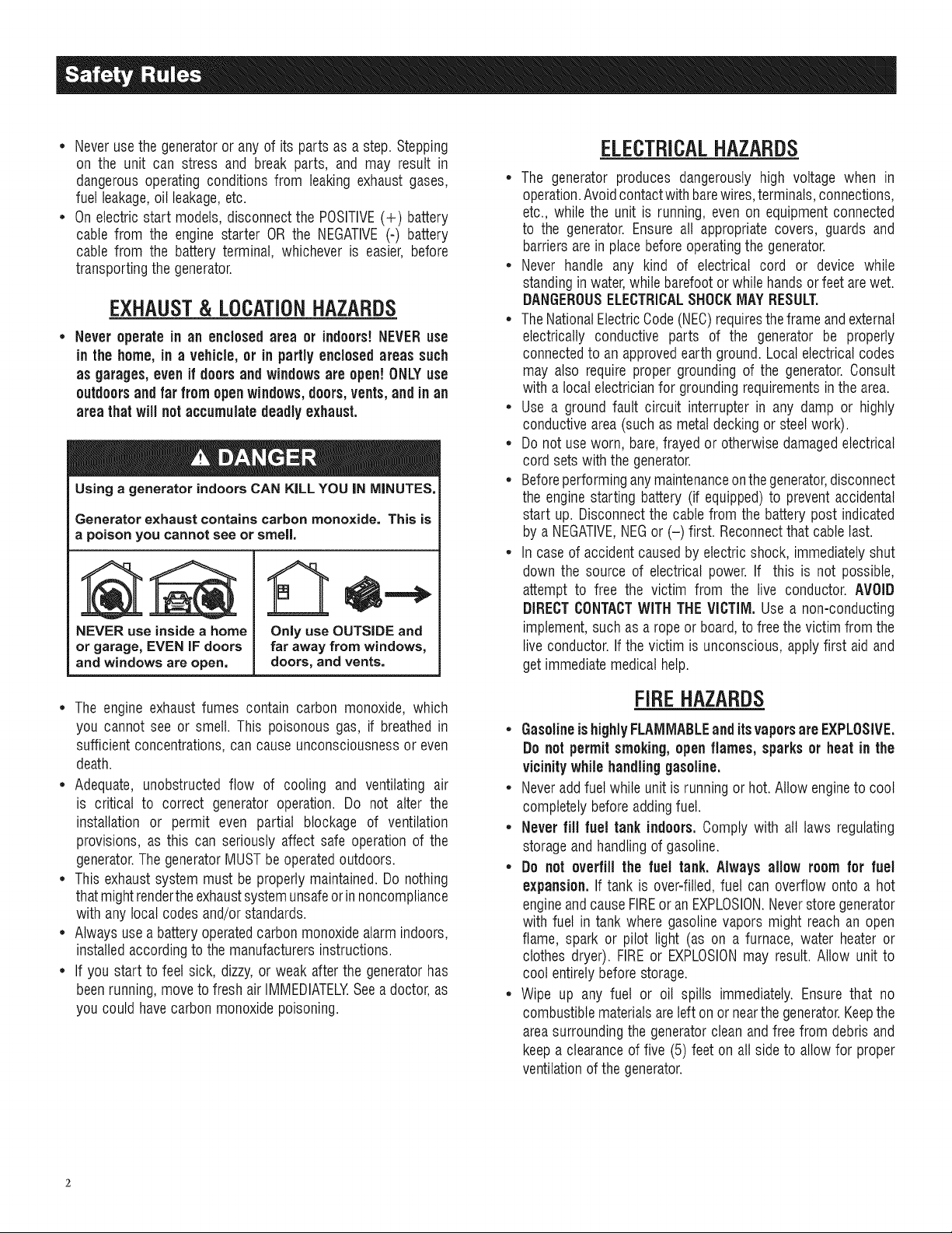
• Never operate in an enclosed area or indoors!NEVERuse
in the home, in a vehicle,or in partly enclosed areas such
as garages,evenif doors and windowsare open! ONLYuse
outdoors and far from openwindows,doors,vents,andinan
areathatwill notaccumulatedeadly exhaust.
Using a generator indoors CAN KILL YOU IN MINUTES,
Generator exhaust contains carbon monoxide. This is
a poison you cannot see or smell,
NEVER use insidea home
or garage,EVEN IF doors
and windows are open.
Only use OUTSIDE and
far away from windows,
doors, and vents=
ELECTRICALHAZARDS
• The generator produces dangerously high voltage when in
operation.Avoidcontactwithbarewires,terminals,connections,
etc., while the unit is running,even on equipmentconnected
to the generator.Ensureall appropriate covers, guards and
barriersarein placebeforeoperatingthegenerator.
• Never handle any kind of electrical cord or device while
standinginwater,while barefootorwhile handsor feet arewet.
DANGEROUSELECTRICALSHOCKMAYRESULT.
• TheNationalElectricCode(NEC)requirestheframe andexternal
electrically conductive parts of the generator be properly
connectedto an approvedearthground.Local electricalcodes
may also require proper grounding of the generator.Consult
with a localelectricianfor groundingrequirementsin the area.
• Use a ground fault circuit interrupter in any damp or highly
conductivearea(such as metaldecking or steelwork).
• Do not useworn, bare,frayed or otherwisedamagedelectrical
cord setswith the generator.
• Beforeperforminganymaintenanceonthegenerator,disconnect
the enginestarting battery (if equipped)to prevent accidental
start up. Disconnectthe cable from the batterypost indicated
by a NEGATIVE,NEGor (-) first. Reconnectthat cable last.
• In caseof accident causedby electricshock, immediatelyshut
down the source of electrical power. If this is not possible,
attempt to free the victim from the live conductor. AVOID
DIRECTCONTACTWITH THEVICTIM, Use a non-conducting
implement,such as a rope or board,to freethevictim from the
live conductor.If the victim is unconscious,applyfirst aidand
getimmediatemedical help.
• The engine exhaustfumes contain carbon monoxide, which
you cannot see or smell. This poisonous gas, if breathed in
sufficientconcentrations,can causeunconsciousnessor even
death.
• Adequate, unobstructed flow of cooling and ventilating air
is critical to correct generator operation. Do not alter the
installation or permit even partial blockage of ventilation
provisions, as this can seriously affect safe operationof the
generator.ThegeneratorMUSTbeoperatedoutdoors.
• Thisexhaustsystemmust be properlymaintained.Do nothing
that mightrendertheexhaustsystemunsafeorinnoncompliance
with any local codes and/orstandards.
• Alwaysuse a batteryoperatedcarbonmonoxidealarmindoors,
installedaccordingto the manufacturersinstructions.
• If you start to feet sick, dizzy,or weak after the generatorhas
beenrunning,moveto fresh air IMMEDIATELYSeea doctor,as
you couldhavecarbonmonoxidepoisoning.
FIREHAZARDS
• GasolineishighlyFLAMMABLEand itsvaporsareEXPLOSIVE.
Do not permitsmoking,open flames, sparksor heat in the
vicinitywhilehandling gasoline.
• Neveraddfuel whileunit isrunning or hot. Allow engineto cool
completelybeforeaddingfuel.
• Never fill fuel tank indoors.Comply with all laws regulating
storageand handlingof gasoline.
• Do not overfill the fuel tank. Always allow roomfor fuel
expansion.If tank is over=filled,fuel can overflow onto a hot
engineandcauseFIREor an EXPLOSION.Neverstoregenerator
with fuel in tank where gasolinevapors might reachan open
flame, spark or pilot light (as on a furnace, water heateror
clothes dryer). FIREor EXPLOSIONmay result. Allow unit to
cool entirelybeforestorage.
• Wipe up any fuel or oil spills immediately. Ensure that no
combustiblematerialsareleft on or nearthe generator.Keepthe
areasurroundingthe generatorclean andfree from debrisand
keepa clearanceof five (5) feet on all side to allow for proper
ventilationof the generator.
* Do notinsert objectsthrough unit's cooling slots.
* Do not operatethe generator if connected electrical devices
overheat,if electricaloutputislost, if engineor generatorsparks
or ifflames or smoke are observedwhileunit is running.
* Keepafire extinguishernearthe generatorat all times.
STANDARDS/#DEX
Intheabsenceof pertinentstandards,codes,regulationsandtaws,
the publishedinformation listedbelowmay be usedas a guideline
foroperationof this equipment.Alwaysreferencethe latestrevision
availablefor the standardslisted.
1. NFPANo. 70, NFPAHANDBOOKOF NATIONALELECTRIC
CODE.
2. Article X, NATIONALBUILDINGCODE,available from the
American InsuranceAssociation, 85 John Street, New York,
N.Y 10038.
3. AGRICULTURALWIRINGHANDBOOK,availablefrom the Food
and EnergyCouncil, 909 UniversityAvenue, Columbia, MO
65201.
4. ASAE EP-3634, INSTALLATIONAND MAINTENANCEOF
FARMSTANDBYELECTRICALSYSTEMS,availablefrom the
AmericanSocietyof AgriculturalEngineers,2950 NilesRoad,
St. Joseph, MI 49085.
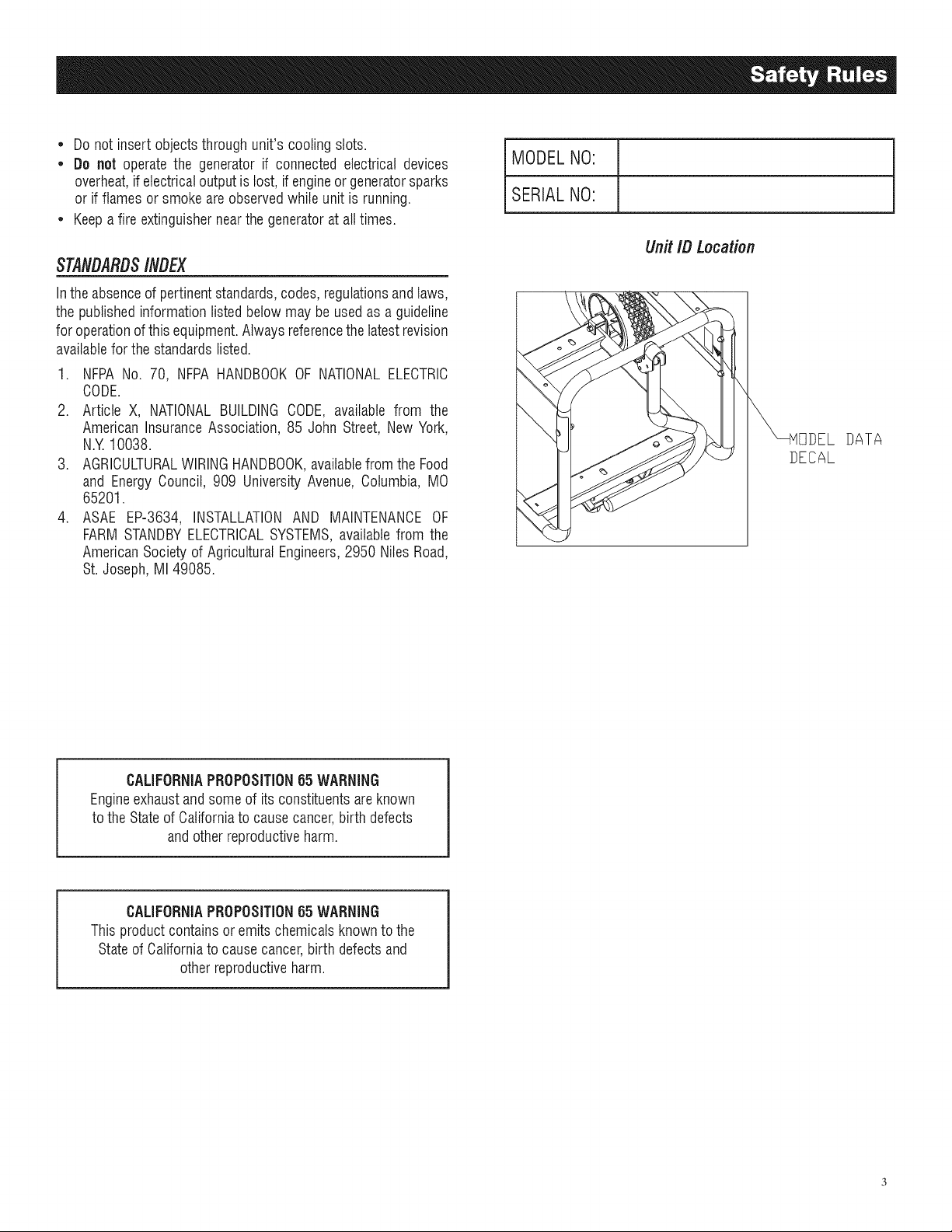
MODELNO:
SERIALNO:
Unit ID Location
DATA
DECAL
CALIFORNIAPROPOSITION65 WARNING
Engineexhaustandsomeof its constituentsareknown
to theStateof Californiato causecancer,birth defects
andotherreproductiveharm.
CALIFORNIAPROPOSITION65 WARNING
This productcontains or emitschemicalsknown tothe
Stateof Californiato causecancer,birth defectsand
otherreproductiveharm.
1.1 UNPACKING
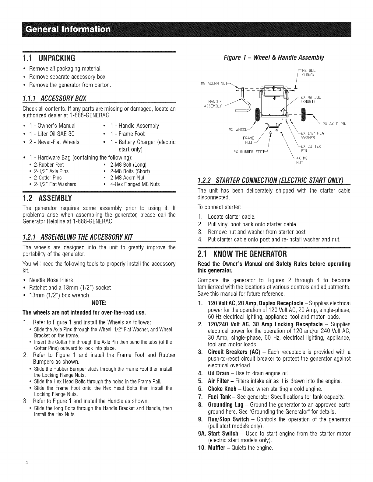
Figure 1 - Wheel & Handle Assembly
• Removeall packagingmaterial.
• Removeseparateaccessorybox.
• Removethegeneratorfrom carton.
1.1.1 ACCESSORYBOX
Checkall contents.If any parts aremissing or damaged,locatean
authorizeddealerat 1-888-GENERAC.
• 1 - Owner'sManual • 1 - HandleAssembly
• 1-LiterOiISAE30 • 1-FrameFoot
• 2 - Never-FlatWheels • 1 - BatteryCharger(electric
start only)
• 1 - HardwareBag (containingthefollowing):
• 2-RubberFeet • 2-M8Bolt(Long)
• 2-1/2" AxlePins • 2-M8Bolts(Short)
• 2-CotterPins • 2-M8AcornNut
• 2-1/2" FlatWashers • 4-HexFlangedM8Nuts
1.2 ASSEMBLY
The generator requires some assembly prior to using it. If
problems arise when assemblingthe generator,please call the
GeneratorHetplineat 1-888-GENERAC.
1.2.1 ASSEMBLINGTHEACCESSORYKIT
The wheels are designed into the unit to greatly improve the
portability ofthe generator.
You will needthe following tools to properlyinstall the accessory
kit.
• NeedleNosePliers
• Ratchetanda 13mm (1/2") socket
• 13mm (1/2") box wrench
NOTE:
The wheels are net intendedfor over-the-road use.
1. Refer to Figure 1 and install the Wheels as follows:
• Slidethe AxlePinsthroughthe Wheel, 1/2" FlatWasher,and Wheel
Bracketon the frame.
• Insertthe CotterPinthroughthe Axle Pinthenbend thetabs (ofthe
OotterPins) outward to lock into place.
2. Refer to Figure 1 and install the Frame Foot and Rubber
Bumpers as shown.
• Slidethe RubberBumperstuds throughthe FrameFootthen install
the Locking FlangeNuts.
• Slidethe HexHeadBoltsthrough the holes in the FrameRail.
• Slide the Frame Foot onto the Hex Head Bolts then install the
LockingFlangeNuts.
3. Refer to Figure 1 and install the Handle as shown.
• Slidethe long Bolts through the HandleBracketand Handle,then
installthe HexNuts.
Y_ H8 ]3r]LT
(LONG)
M8 ACORN NUT--,..,. -- -- -- L
\_ _ /_2x M8 BOLT
HANBLE _ _%, II II/ (SHORT)
.
FRAHE / 7" \ \ WASHER
FOOTJ / _ _2X COTTER
8X RUBBER FOOTJ _xPI:8
NUT
1.2.2 STARTERCONNECTION(ELECTRICSTARTONLY)
The unit has been deliberately shipped with the starter cable
disconnected.
Toconnectstarter:
1. Locatestarter cable.
2. Pullvinyl boot backonto startercable.
3. Removenut and washerfrom starter post.
4. Putstarter cableontopost and re-installwasher and nut.
2.1 KNOWTHEGENERATOR
Read the Owner'sManual and Safety Rules before operating
this generator.
Compare the generator to Figures 2 through 4 to become
familiarizedwiththelocations of variouscontrolsandadjustments.
Savethis manualfor future reference.
1. 120 VoltAC,20 Amp, DuplexReceptacle- Supplieselectrical
powerfor theoperationof 120VoltAC,20 Amp,single-phase,
60 Hzelectricallighting,appliance,tool and motor loads.
2. 120/240 Volt AC, 30 Amp LockingReceptacle - Supplies
electricalpowerfor the operationof 120 and/or240 VoltAC,
30 Amp, single-phase, 60 Hz, electrical lighting, appliance,
tool andmotor loads.
3. CircuitBreakers(AC) - Eachreceptacleis providedwith a
push-to-reset circuit breakerto protectthe generatoragainst
electricaloverload.
4. Oil Drain- Useto drainengineoil.
5. Air Filter - Filters intakeair as it isdrawn into the engine.
6. ChokeKnob- Usedwhen starting a cold engine.
7. FuelTank- SeegeneratorSpecificationsfor tank capacity.
8. Grounding Lug - Groundthe generatorto an approvedearth
groundhere.See"Groundingthe Generator"for details.
g. Run/Step Switch - Controls the operation of the generator
(pullstart models only).
gA. Start Switch - Used to start enginefrom the starter motor
(electricstart modelsonly).
10. Muffler - Quietsthe engine.
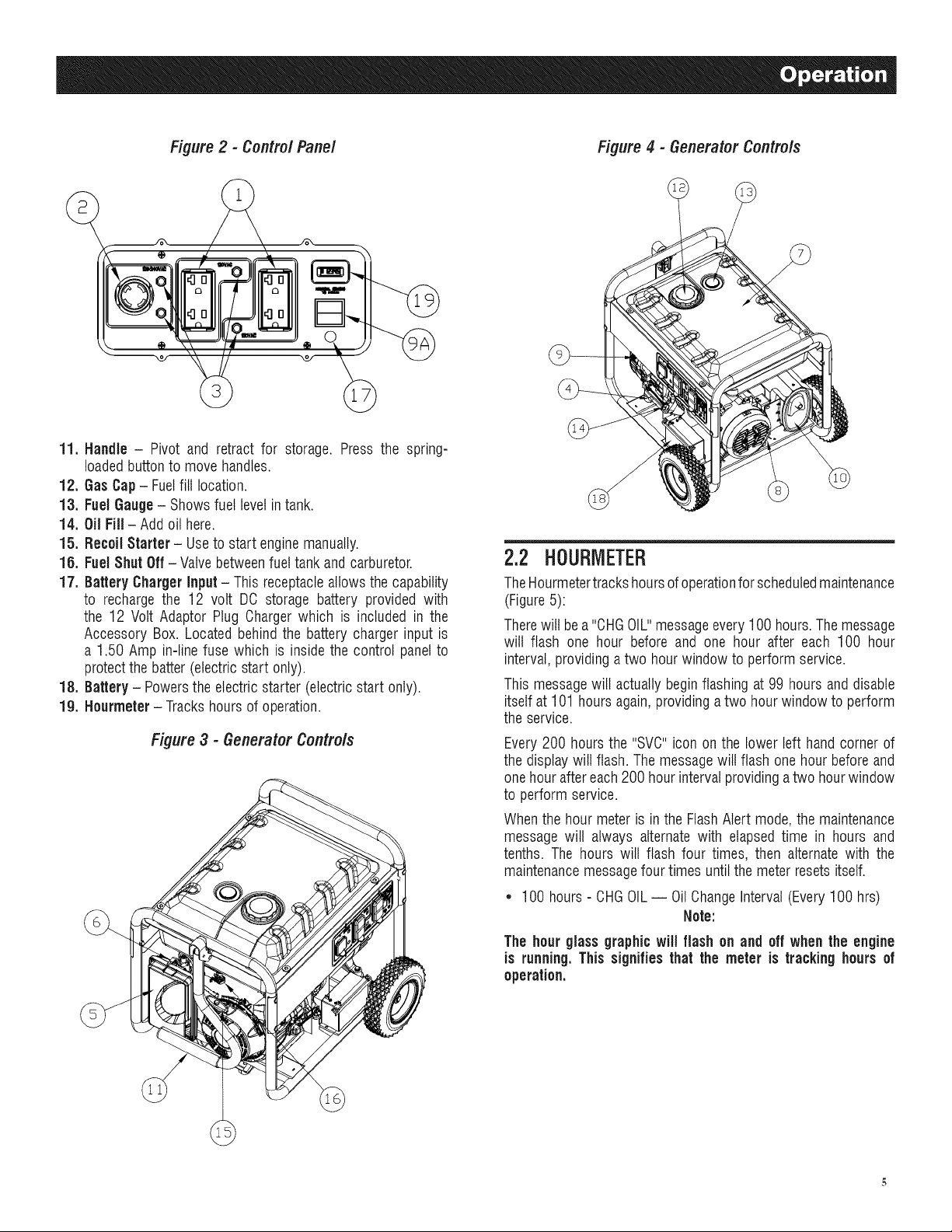
Figure 2 - Contro/ Pane/ Figure 4 - Generator Contro/s
11. Handle - Pivot and retract for storage. Press the spring-
loadedbuttonto movehandles.
12. GasCap- Fuelfill location.
13. FuelGauge- Showsfuel levelin tank.
14. OilFill - Add oil here.
15. Recoil Starter - Useto start enginemanually.
15. Fuel Shut Off- Valvebetweenfuel tank and carburetor.
17. Battery Charger Input - This receptacleallowsthe capability
to recharge the 12 volt DC storage battery provided with
the 12 Volt Adaptor PlugChargerwhich is included in the
Accessory Box. Located behindthe battery charger input is
a 1.50 Amp in-line fuse which is inside the control panelto
protectthe batter(electricstart only).
18. Battery - Powersthe electricstarter (electricstart only).
19. Hourmeter - Trackshours of operation.
Figure3 - GeneratorControls
2.2 HOURIVIETER
TheHourmetertrackshoursofoperationforscheduledmaintenance
(Figure5):
Therewill be a"CHGOIL"messageevery100 hours.Themessage
will flash one hour before and one hour after each 100 hour
interval,providinga two hourwindow to performservice.
This messagewill actually beginflashing at 99 hours and disable
itselfat 101 hoursagain,providing atwo hourwindow to perform
theservice.
Every200 hoursthe "SVC"icon on the lower left hand corner of
thedisplay will flash. Themessagewill flash one hourbefore and
onehour aftereach200 hourintervalprovidingatwo hourwindow
to perform service.
Whenthe hour meter is inthe FlashAlert mode, the maintenance
message will always alternatewith elapsedtime in hours and
tenths. The hours wilt flash four times, then alternatewith the
maintenancemessagefourtimes untilthe meter resetsitself.
* 100 hours - CHGOIL-- OilChangeInterval(Every100 hrs)
Note:
The hour glassgraphicwill flash on and off when the engine
is running.This signifiesthat the meter is tracking hours of
operation.
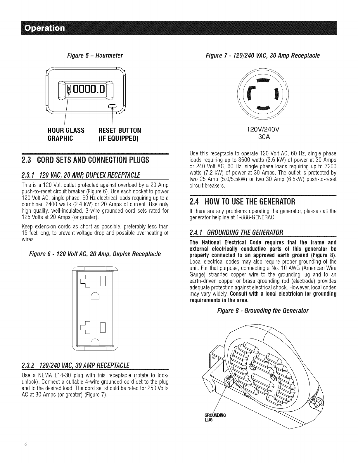
Figure 5 - Hourmeter Figure 7 - 120/240 VAC,30 Amp Receptacle
0000.0
HOURGLASS
GRAPHIC
RESETBUTTON
(IF EQUIPPED)
2.3 CORDSETSANDCONNECTIONPLUGS
2.3.1 120VAC,20 AMP,DUPLEXRECEPTACLE
This is a120 Volt outlet protectedagainst overloadby a20 Amp
push-to-resetcircuitbreaker(Figure6). Useeachsocketto power
120 Volt AC, singlephase,60 Hzelectricalloadsrequiringup to a
combined 2400 watts (2.4 kW) or 20 Amps of current. Useonly
high quality,well-insulated, 3-wire groundedcord sets ratedfor
125 Volts at 20 Amps (or greater).
Keep extensioncords as short as possible, preferablyless than
15 feet long, to preventvoltagedrop and possibleoverheatingof
wires.
Figure 6 - 120 Vo/t AC, 20 Amp, Duplex Receptac/e
120V/240V
30A
Use this receptacleto operate120 Volt AC, 60 Hz, single phase
loads requiringup to 3600 watts (3.6 kW) of powerat 30Amps
or 240 Volt AC, 60 Hz,single phaseloads requiring up to 7200
watts (7.2 kW) of power at 30 Amps. The outlet is protected by
two 25 Amp (5.0/5.5kW) or two 30 Amp (6.5kW) push-to-reset
circuit breakers.
2.4 HOW TOUSETHEGENERATOR
If thereare any problems operatingthe generator,pleasecall the
generatorhelplineat 1-888-GENERAC.
2.4.1 GROUNDINGTHEGENERATOR
The National Electrical Code requires that the frame and
external electrically conductiveparts of this generator be
properlyconnectedto an approved earth ground (Figure 8).
Local electrical codes may also require proper grounding of the
unit. Forthat purpose, connectinga No. 10 AWG (AmericanWire
Gauge) stranded copper wire to the grounding lug and to an
earth-driven copper or brass grounding rod (electrode) provides
adequateprotectionagainstelectricalshock. However,local codes
may vary widely. Consultwith a localelectricianfor grounding
requirementsin the area.
D
2.3.2 120/240VAC,30 AMPRECEPTACLE
Use a NEMA L14-30 plug with this receptacle (rotate to lock!
unlock). Oonnecta suitable4-wire groundedcord set to the plug
andto thedesiredtoad.Thecordset should be ratedfor 250 Volts
ACat30 Amps (or greater)(Figure7).
Figure8 - Groundingthe Generator
Propergroundingofthe generatorwill help preventelectrical
shockin the event of a ground fault condition in the generator
or in connectedelectrical devices. Proper grounding also helps
dissipate static electricity, which often builds up in ungrounded
devices.
2.4.2 CONNECTINGELECTR/CALLOADS
DONOTconnect240 Volt loadsto 120Volt receptacles.DONOT
connect 3-phaseloads to the generator.DONOTconnect 50 Hz
loadsto thegenerator.
* Let engine stabilize and warm up for a few minutes after
starting.
* Plug in and turn on the desired 120 or 240 Volt AO, single
phase,60 Hzelectricalloads.
* Add up the ratedwatts (or amps) of all loadsto be connected
at onetime. This total should not be greaterthan (a) the rated
wattage/amperagecapacity of the generator or (b) circuit
breakerratingof thereceptaclesupplyingthe power.See"Don't
Overloadthe Generator".
2.5 DON'TOVEBLOADTHEGENEBATOB
Overloadinga generator in excess of its ratedwattage capacity
can result in damageto the generatorandto connectedelectrical
devices.Observethefollowing to preventoverloadingthe unit:
* Addupthetotal wattageofall electricaldevicesto be connected
at one time. This total should NOT be greater than the
generator'swattage capacity.
* The ratedwattage of lights can be takenfrom light bulbs. The
ratedwattageof tools, appliancesand motors can usually be
found on a data labelor decalaffixedto the device.
* If the appliance,toot or motor does not givewattage, multiply
voltstimes ampereratingto determinewatts (voltsx amps =
watts).
* Some electric motors, such as induction types, require about
threetimes morewatts of powerfor startingthan for running.
This surge of power lasts only a few seconds when starting
such motors.Makesureto allowfor high startingwattagewhen
selectingelectrical devicesto connectto the generator:
1. Figurethe watts neededtostart the largestmotor.
2. Add to that figure the running watts of all other connected
loads.
TheWattageReferenceGuideis providedto assist in determining
how many items the generatorcan operateatonetime.
NOTE:
All figuresare approximate. See data label on appliance for
wattage requirements.
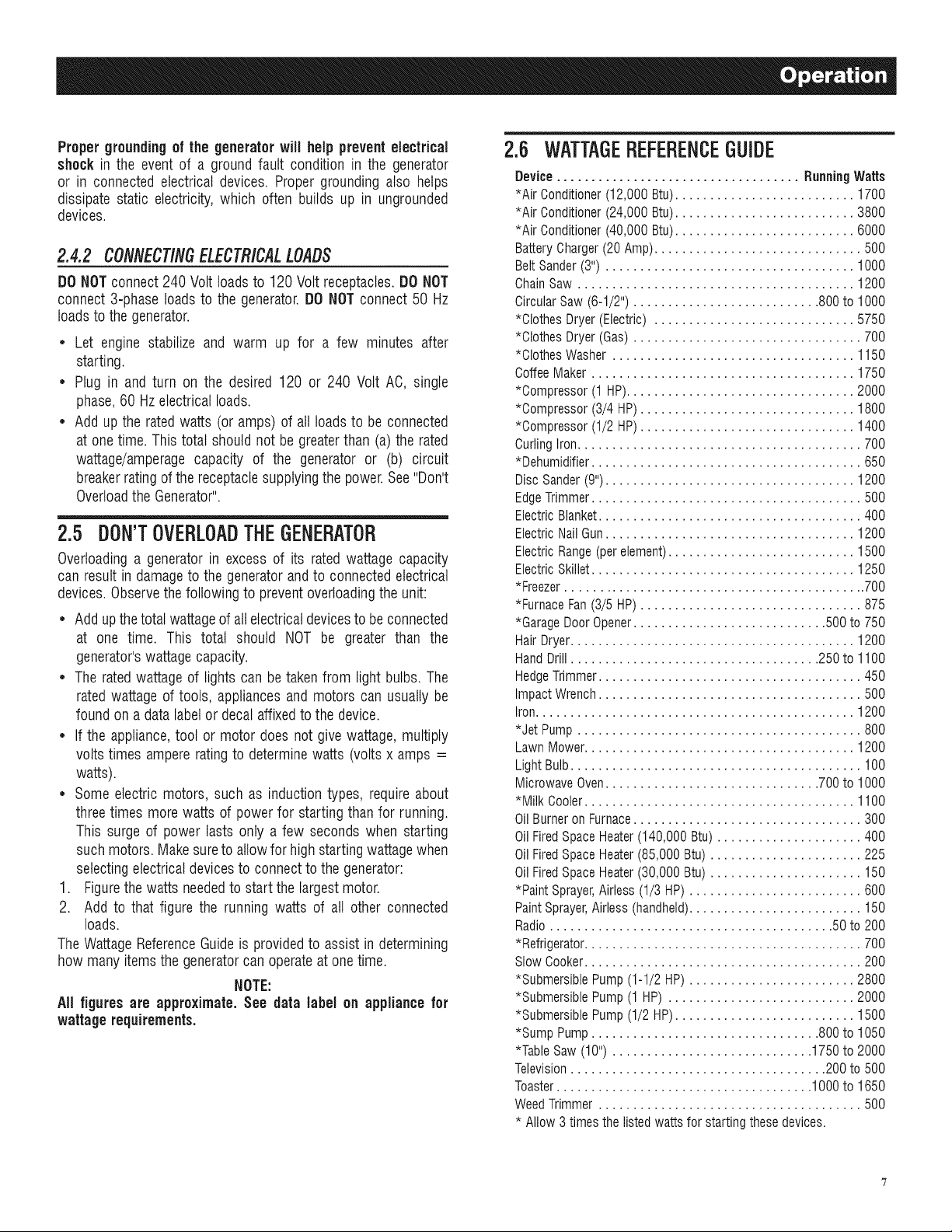
2.6 WATTAGEBEFEBENCEGUIDE
Device ................................... RunningWatts
*Air Conditioner(12,000 Btu).......................... 1700
*Air Conditioner(24,000 Btu).......................... 3800
*Air Conditioner(40,000 Btu).......................... 6000
BatteryCharger(20 Amp).............................. 500
BeltSander(3") .................................... 1000
ChainSaw ........................................ 1200
CircularSaw (6-1/2") ........................... 800to 1000
*Clothes Dryer (Electric) ............................. 5750
*Clothes Dryer (Gas) ................................. 700
*Clothes Washer ................................... 1150
CoffeeMaker ...................................... 1750
*Compressor (1 HP)................................. 2000
*Compressor (3/4 HP)............................... 1800
*Compressor (1/2 HP)............................... 1400
CurlingIron......................................... 700
*Dehumidifier....................................... 650
Disc Sander(9").................................... 1200
EdgeTrimmer....................................... 500
Electric Blanket...................................... 400
Electric NailGun.................................... 1200
Electric Range(per element)........................... 1500
Electric Skillet...................................... 1250
*Freezer............................................ 700
*FurnaceFan(3/5 HP) ................................ 875
*GarageDoor Opener............................ 500 to 750
Hair Dryer......................................... 1200
HandDrill .................................... 250to 1100
HedgeTrimmer...................................... 450
Impact Wrench...................................... 500
Iron.............................................. 1200
*Jet Pump ......................................... 800
Lawn Mower....................................... 1200
LightBulb.......................................... 100
Microwave Oven............................... 700to 1000
*Milk Cooler....................................... 1100
OilBurneron Furnace................................. 300
OilFiredSpace Heater(140,000 Btu) ..................... 400
OilFiredSpace Heater(85,000 Btu) ...................... 225
OilFiredSpace Heater(30,000 Btu) ...................... 150
*Paint Sprayer,Airless (1/3 HP) ......................... 600
PaintSprayer,Airless (handheld)......................... 150
Radio ......................................... 50 to 200
*Refrigerator........................................ 700
SlowCooker........................................ 200
*Submersible Pump(1-1/2 HP) ........................ 2800
*SubmersiblePump (1 HP) ........................... 2000
*Submersible Pump(1/2 HP).......................... 1500
*Sump Pump................................. 800to 1050
*Table Saw (10") ............................. 1750to 2000
Television..................................... 200 to 500
Toaster..................................... 1000to 1650
WeedTrimmer ...................................... 500
* Allow3 times the listedwatts for starting these devices.
2.7 BEFORESTARTINGTHEGENERATOR
Priorto operatingthe generator,engineoil and gasolinewill need
to be added,as follows:
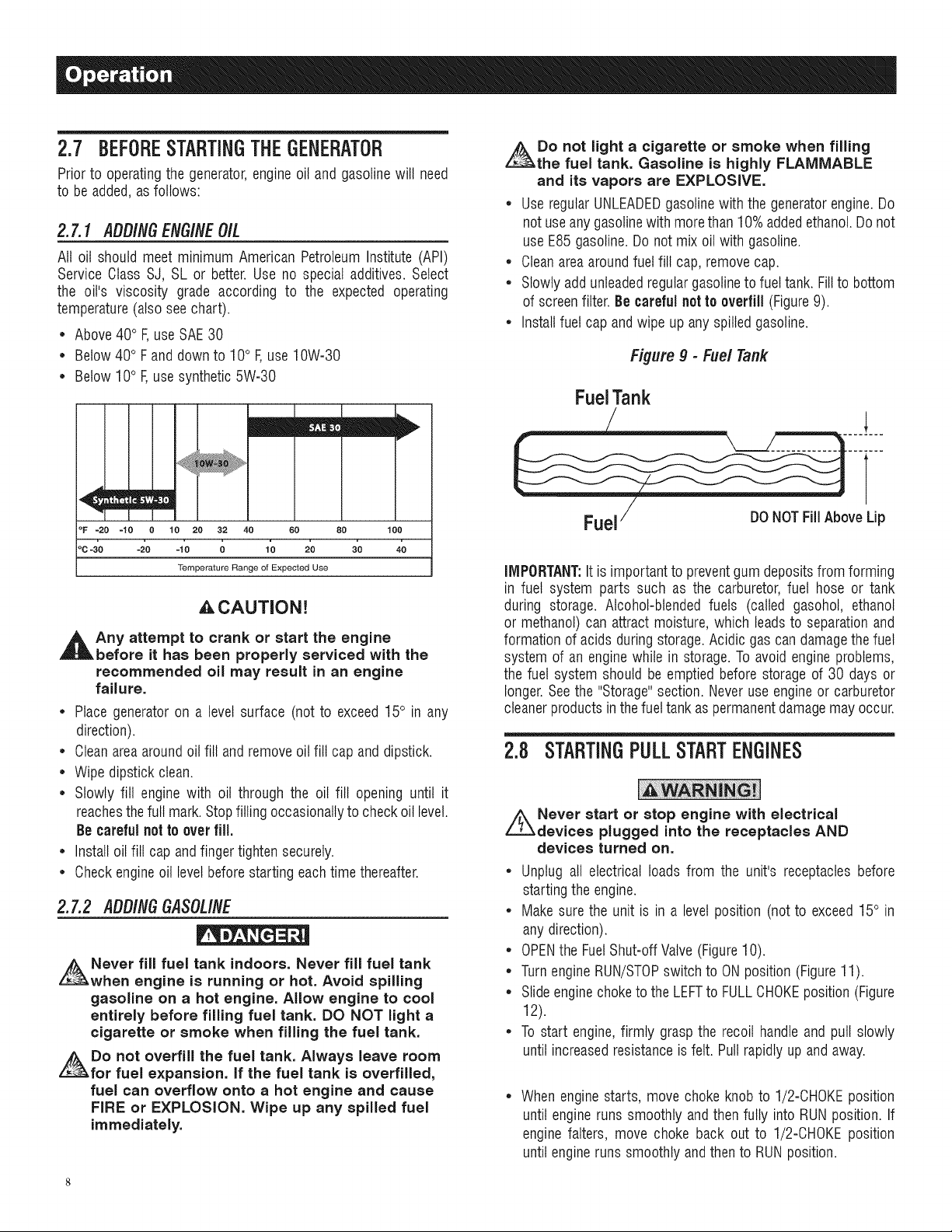
2.7.1 ADD/NGENG/NEO/L
All oil should meet minimum American PetroleumInstitute (API)
Service Class SJ, SL or better.Use no special additives. Select
the oil's viscosity grade according to the expected operating
temperature(also seechart).
* Above40° F,use SAE30
* Below 40° F and downto 10° F,use 10W-30
* Below 10° F,use synthetic 5W-30
mEm!
ZEn
°F =20 =10 0 10 20 32 40 60 80 100
oc-3'0 -_o -;0 o 1'0 2'0 3'0 4o
Temperature Range of Expected Use
_,CAUTION!
,_t Any attempt to crank or start the engine
before it has been properly serviced with the
recommended oil may result in an engine
failure.
* Place generator on a levelsurface (not to exceed15° in any
direction).
* Cleanareaaroundoil fill andremoveoil fill cap anddipstick.
* Wipe dipstick clean.
* Slowly fill engine with oil through the oil fill opening until it
reachesthefull mark.Stopfilling occasionallyto checkoil level.
Becarefulnotto overfill.
* Install oil fill cap andfinger tightensecurely.
* Checkengineoil levelbeforestarting eachtime thereafter.
2.7.2 ADDINGGASOLINE
Never fill fuel tank indoors. Never fill fuel tank
when engine is running or hot. Avoid spilling
gasoline on a hot engine. Allow engine to cool
entirely before filling fuel tank. DO NOT light a
cigarette or smoke when filling the fuel tank.
Do not overfill the fuel tank. Always leave room
for fuel expansion. If the fuel tank is overfilled,
fuel can overflow onto a hot engine and cause
FIRE or EXPLOSION. Wipe up any spilled fuel
immediately.
Do not light a cigarette or smoke when filling
the fuel tank. Gasoline is highly FLAMMABLE
and its vapors are EXPLOSIVE.
* Use regularUNLEADEDgasolinewith the generatorengine.Do
notuseany gasolinewith more than 10%addedethanol.Do not
useE85 gasoline.Do not mix oil with gasoline.
* Cleanareaaroundfuel fill cap,removecap.
* Slowly addunleadedregulargasolineto fueltank. Fillto bottom
of screenfilter.Be carefulnot to overfill (Figure9).
* Install fuel cap andwipe up any spilledgasoline.
Figure9 - Fuel Tank
FuelTank
Fuel/ DONOTFillAbove Lip
IMPORTANT:It is important to preventgum depositsfrom forming
in fuel system parts such as the carburetor,fuel hose or tank
during storage. Alcohol-blendedfuels (called gasohol, ethanol
or methanol)can attract moisture, which leadsto separationand
formationof acids duringstorage.Acidic gascandamagethefuel
system of an enginewhile in storage. To avoid engineproblems,
the fuel system should be emptiedbefore storage of 30 days or
longer.Seethe "Storage"section. Neveruseengineor carburetor
cleanerproducts inthe fuel tank aspermanentdamagemay occur.
2.8 STARTINGPULLSTARTENGINES
Never start or stop engine with electrical
devices plugged into the receptacles AND
devices turned on.
* Unplug all electrical loads from the unit's receptaclesbefore
startingthe engine.
* Make surethe unit is in a levelposition (notto exceed15° in
anydirection).
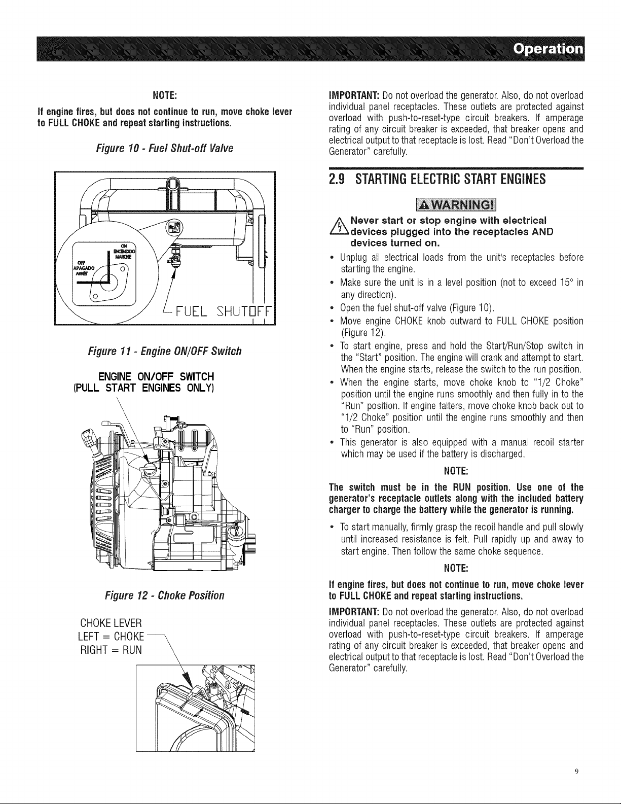
* OPENthe FuelShut-offValve(Figure10).
* TurnengineRUN/STOPswitch to ON position(Figure11).
* Slideenginechoketo the LEFTto FULLCHOKEposition(Figure
12).
. To start engine,firmly graspthe recoil handleand pull slowly
until increasedresistanceisfelt. Pullrapidly up and away.
Whenenginestarts, move choke knobto 1/2-CHOKEposition
until engineruns smoothly andthen fully into RUNposition.If
engine falters, move choke back out to 1/2-CHOKEposition
untilengineruns smoothly andthento RUNposition.
NOTE:
if enginefires, butdoesnot continueto run, movechokelever
to FULLCHOKEand repeatstartinginstructions.
Figure 10 - FuelShut-offVaNe
FUEL SHUTOFF
Figure 11 - Engine ON/OFF Switch
ENGINE ON/OFF SWITCH
(PULL START ENGINES ONLY)
IMPORTANT:Donotoverloadthe generator.Also,do not overload
individual panel receptacles.These outlets are protectedagainst
overload with push-to-reset-type circuit breakers. If amperage
rating of any circuit breakeris exceeded,that breakeropensand
electricaloutputtothat receptacleis lost.Read"Don't Overloadthe
Generator"carefully.
2.9 STARTINGELECTRICSTARTENGINES
Never start or stop engine with electrical
devices plugged into the receptacles AND
devices turned on.
• Unplug all electrical loads from the unit's receptaclesbefore
startingthe engine.
• Makesurethe unit is in a levelposition (notto exceed15° in
anydirection).
• Openthefuel shut-off valve (Figure10).
• Move engine CHOKEknob outward to FULLCHOKEposition
(Figure12).
• To start engine, press and hold the Start/Run/Stopswitch in
the"Start" position. The enginewill crankand attemptto start.
Whenthe enginestarts, releasethe switch to the runposition.
• When the engine starts, move choke knob to "1/2 Choke"
position until the engine runssmoothly and thenfully in to the
"Run" position.If enginefalters, move chokeknob back outto
"1/2 Choke"position until the engine runs smoothly and then
to "Run" position.
• This generator is also equippedwith a manual recoil starter
which may be usedif the batteryis discharged.
NOTE:
Figure 12 - Choke Position
CHOKELEVER
LEFT = CHOKE--
RIGHT = RUN
The switch must be in the RUN position. Use one of the
generator's receptacle outlets along with the includedbattery
chargerto chargethe battery while the generator is running.
• Tostart manually,firmly grasp the recoil handleand pull slowly
until increasedresistance is felt. Pull rapidly up and away to
start engine.Thenfollow the samechoke sequence.
NOTE:
if enginefires, but does not continueto run,move chokelever
to FULLCHOKEand repeatstartinginstructions.
IMPORTANT:Donot overloadthe generator.Also,do not overload
individual panel receptacles.These outlets are protectedagainst
overload with push-to-reset-type circuit breakers. If amperage
rating of any circuit breakeris exceeded,that breakeropensand
electricaloutputtothat receptacleis lost.Read"Don't Overloadthe
Generator"carefully.

2.10STOPPINGTHEENGINE
• Shutoff all loads,then unplugtheelectricalloadsfrom generator
panelreceptacles.Neverstart or stop theenginewith electrical
devicespluggedin andturnedon.
• Let engine run at no-loadfor several minutes to stabilizethe
internaltemperaturesof engineandgenerator.
• MoveRun/Stopswitch to OFFposition.
• Closefuelvalve.
2.11LOWOiLLEVELSHUTDOWNSYSTEM
Theengineis equippedwith a low oil levelsensorthat shutsdown
the engineautomaticallywhenthe oil leveldropsbelow a specified
level. If the engine shuts down by itself and the fuel tank has
enoughgasoline,checkengineoil level.
2. Unplugbattery chargerfrom wall outlet andcontrol paneljack
whengeneratoris goingto be in use.
NOTE:
Do not use the battery chargerfor more than 48 hoursat one
charge.
Figure 13 - Battery Charger Jack
BATTERY
CHARGER
2.11.1 SENSINGLOWOILLEVEL
If the system senses a low oil level during operation,the engine
shuts down. The enginewill not run until the oil has beenrefilled
to the properlevel.
2.12CHARGINGTHEBATTERY(ELECTRICSTART
UNITSONLY)
Storage batteries give off explosive hydrogen
gas while recharging. An explosive mixture will
remain around the battery for a long time after
it has been charged. The slightest spark can
ignite the hydrogen and cause an explosion.
Such an explosion can shatter the battery and
cause blindness or other serious injury.
,_Do not permit smoking, open flame, sparks
or any other source of heat around a battery.
Wear protective goggles, rubber apron and
rubber gloves when working around a battery.
Battery electrolyte fluid is an extremely
corrosive sulfuric acid solution that can cause
severe burns, if spill occurs flush area with
clear water immediately.
NOTE:
The battery shipped withthe generator has been fully charged.
A battery may lose some of its charge when not in use for
prolongedperiodsof time. If the battery isunable to crankthe
engine, plugin the 12V chargerincludedin the accessory box
(seesection"Chargingthe Battery").RUNNINGTHEGENERATOR
DOESNOTCHARGETHEBATTERY.
Usebatterychargerplugto keepthebattery chargedandreadyfor
use. Batterychargingshouldbe done in a dry location.
1. Plugchargerinto "BatteryChargerInput" jack, locatedon the
control panel.Plugwall receptacleendof the batterycharger
into a 120 VoltACwalt outlet(Figure13).
1o
INPUT
3.1 MAINTENANCESCHEDULE
Follow the calendar intervals. More frequent service is required
whenoperatingin adverseconditionsnotedbelow.
CheckOil Level
ChangeOil:_
CheckValveClearance
ServiceAir Filter
ReplaceSparkPlug
$ Changeoil after first 30 hours of operationthen every season.
* Changeoiland oilfilter every monthwhen operatingunderheavyload or in high
temperatures.
** Cleanmore often under dirty or dusty operatingconditions. Replaceair filter
parts if they cannot beadequatelycleaned.
*** Check valve clearance and adjust if necessary after first 50 hours of
operationand every 100 hours thereafter.
*Every 100 hoursor EverySeason
** Every200 hoursor EverySeason
3.2 PRODUCTSPECIFICATIONS
3.2.1 GENERATORSPECIFICATIONS
RatedPower............................................................... 5.0/5.5/6.5 kW**
SurgePower...............................................................6.25/6.88/8.0 kW
RatedACVoltage...................................................................... 120/240
RatedAC Load
Current@ 240V (5.0/5.5/6.5 kW) ..................20.8/22.9/27.1 Amps**
Current@ 120V (5.0/5.5/6.5 kW) ..................41.6/45.8/54.2 Amps**
RatedFrequency.................................................... 60 Hz@ 3600 RPM
Phase................................................................................ SinglePhase
** Maximumwattageandcurrentaresubjectto,andlimitedby,suchfactors
asfuelBtucontent,ambienttemperature,altitude,enginecondition,etc..
Maximumpowerdecreasesabout3.5%foreach1,000feetabovesealevel;
andwillalsodecreaseabout1%foreach6°C (10°F)above16° C(60°F)
ambienttemperature.
At EachUse
***Every Season
EverySeason
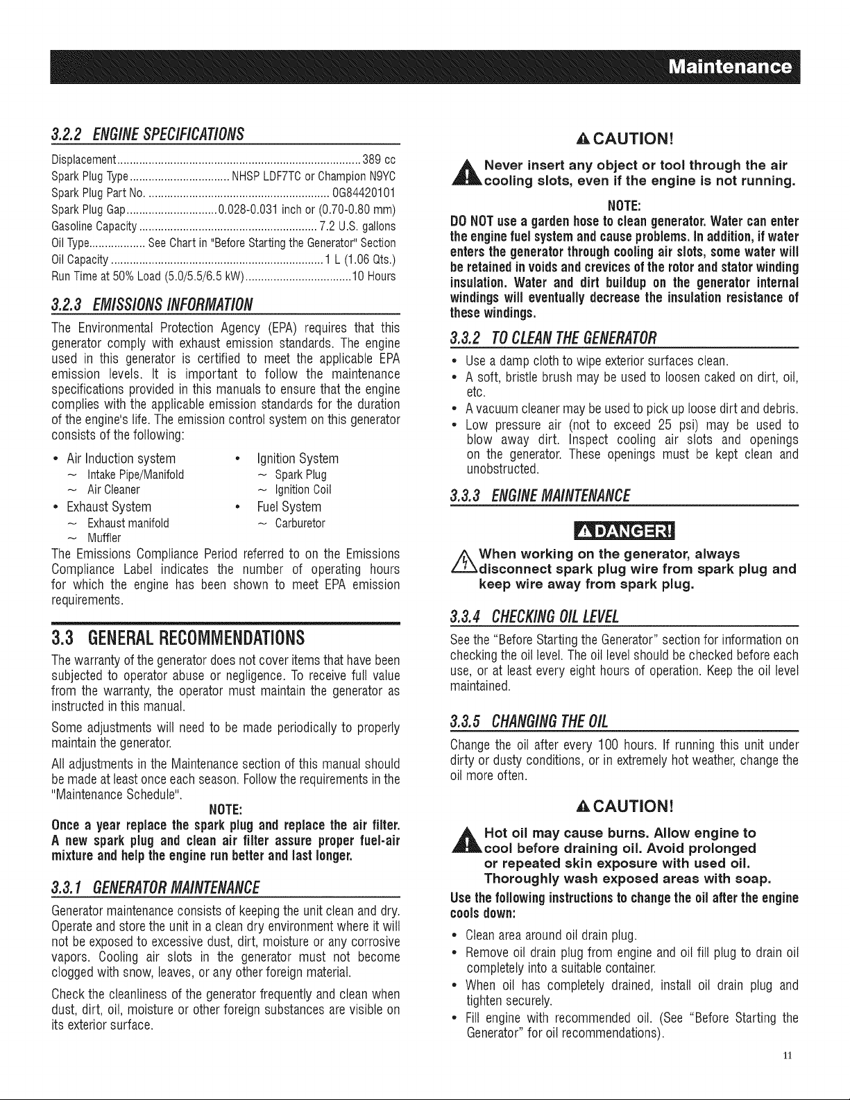
3.2.2 ENG/NESPEC/F/CAT/ONS
Displacement.............................................................................. 389 cc
SparkPlugType................................ NHSPLDF7TCor ChampionN9YC
SparkPlug PartNo........................................................... 0G84420101
SparkPlug Gap.............................0.028-0.031 inch or (0.70-0.80 mm)
GasolineCapacity......................................................... 7.2 U.S. gallons
OilType.................. SeeChart in "Before Starting the Generator"Section
OilCapacity.................................................................... 1 L (1.06 Qts.)
RunTime at 50% Load (5.0/5.5/6.5 kW)..................................10 Hours
3.2.3 EMISSIONSINFORMATION
The Environmental Protection Agency (EPA) requires that this
generatorcomply with exhaustemission standards. The engine
used in this generator is certified to meet the applicable EPA
emission levels. It is important to follow the maintenance
specifications provided in this manualsto ensurethat the engine
complies with the applicableemission standardsfor the duration
of theengine'slife. The emissioncontrol system onthis generator
consists ofthe following:
* Air Induction system * Ignition System
IntakePipe/Manifold - SparkPlug
Air Cleaner _ Ignition Coil
* Exhaust System * Fuel System
Exhaustmanifold _ Carburetor
Muffler
The Emissions Compliance Period referredto on the Emissions
Compliance Label indicates the number of operating hours
for which the engine has been shown to meet EPA emission
requirements.
3.3 GENERALRECOMMENDATIONS
Thewarranty of the generatordoesnotcover itemsthathave been
subjectedto operatorabuse or negligence.To receive full value
from the warranty, the operatormust maintainthe generatoras
instructed inthis manual.
Some adjustmentswill needto be made periodicallyto properly
maintainthegenerator.
All adjustments in the Maintenancesection of this manualshould
bemadeat leastonceeachseason.Followthe requirementsinthe
"MaintenanceSchedule".
NOTE:
Once a year replace the sparkplug and replace the air filter.
A new spark plug and clean air filter assure properfuel-air
mixture and helpthe engine runbetter and last longer.
3.3.1 GENERATORMAINTENANCE
Generatormaintenanceconsists of keepingthe unit clean and dry.
Operateandstorethe unitin a clean dry environmentwhere it will
not be exposedto excessivedust, dirt, moisture or any corrosive
vapors. Cooling air slots in the generator must not become
cloggedwith snow, leaves,or anyother foreign material.
Checkthe cleanlinessof the generatorfrequently andclean when
dust, dirt, oil, moisture or other foreign substancesarevisible on
its exteriorsurface.
A.CAUTION!
_h Never insert any object or tool through the air
cooling slots, even if the engine is not running.
NOTE:
DONOTuse a gardenhoseto cleangenerator. Water canenter
the enginefuel systemand causeproblems.In addition, if water
enters thegenerator throughcoolingair slots,some water will
be retainedinvoidsand crevicesof the rotorand statorwinding
insulation.Water and dirt buildup on the generator internal
windingswill eventually decreasetheinsulationresistanceof
these windings.
3.3.2 TOCLEANTHEGENERATOR
* Usea damp cloth to wipe exteriorsurfaces clean.
* A soft, bristle brush may be used to loosencaked on dirt, oil,
etc.
* Avacuumcleanermay beusedto pick uploosedirt anddebris.
* Low pressure air (not to exceed 25 psi) may be used to
blow away dirt. Inspect cooling air slots and openings
on the generator.These openings must be kept clean and
unobstructed.
3.3.3 ENGINEMAINTENANCE
/_When working on the generator, always
disconnect spark plug wire from spark plug and
keep wire away from spark plug.
3.3.4 CHECKINGOILLEVEL
Seethe "BeforeStartingthe Generator"sectionfor informationon
checkingthe oil level.The oil levelshouldbe checkedbeforeeach
use, or at leastevery eight hours of operation.Keepthe oil level
maintained.
3.3.5 CHANGINGTHEOIL
Changethe oil after every 100 hours. If runningthis unit under
dirty or dusty conditions, or in extremelyhotweather,changethe
oil moreoften.
,&CAUTION!
,_Hot oil may cause burns. Allow engine to
cool before draining oil. Avoid prolonged
or repeated skin exposure with used oil.
Thoroughly wash exposed areas with soap.
Use thefollowinginstructionsto changethe oil after the engine
coolsdown:
* Cleanareaaroundoil drainplug.
* Removeoil drain plug from engine and oil fill plug to drainoil
completelyinto a suitablecontainer.
* When oil has completely drained, install oil drain plug and
tightensecurely.
* Fill enginewith recommendedoil. (See "Before Starting the
Generator"for oil recommendations).
11
• Wipeup anyspilledoil.
• Disposeof usedoil at a propercollectioncenter.
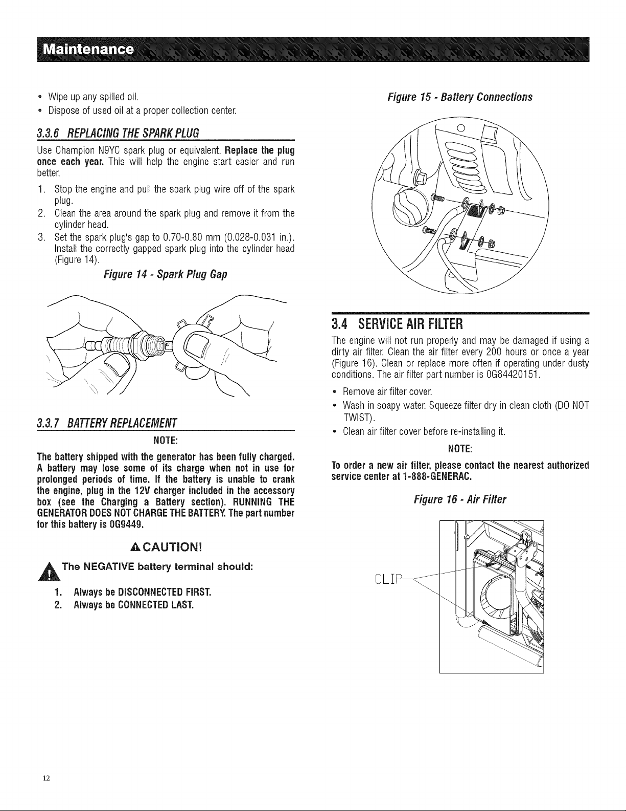
3.3.6 REPLACINGTHESPARKPLUG
Use ChampionN9YCspark plug or equivalent.Replace the plug
once each year. This will help the engine start easier and run
better.
1. Stopthe engineand pull the spark plug wire off of the spark
plug.
2. Cleanthe area aroundthe spark plug and remove it from the
cylinder head.
3. Setthe spark plug's gap to 0.70-0.80 mm (0.028-0.031 in.).
Installthe correctly gappedspark plug into the cylinderhead
(Figure14).
Figure 14 - Spark Plug Gap
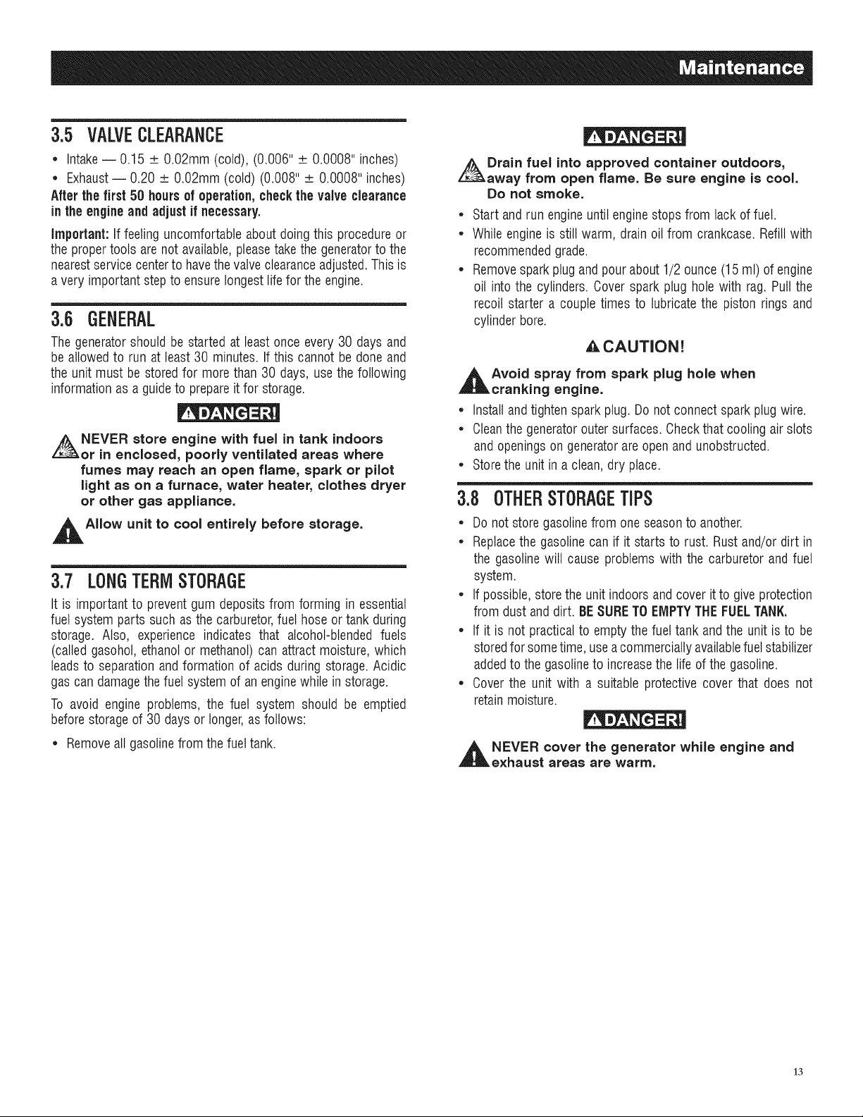
3.3.7 BATTERYREPLACEMENT
NOTE:
Thebatteryshippedwith the generator hasbeen fully charged.
A battery may lose some of its charge when not in use for
prolongedperiodsof time. If the battery is unable to crank
the engine,plug in the 12V chargerincludedin the accessory
box (see the Charging a Battery section). RUNNING THE
GENERATORDOESNOTCHARGETHEBATTERY.Thepartnumber
for this battery is 069449.
Figure15 - Battery Connections
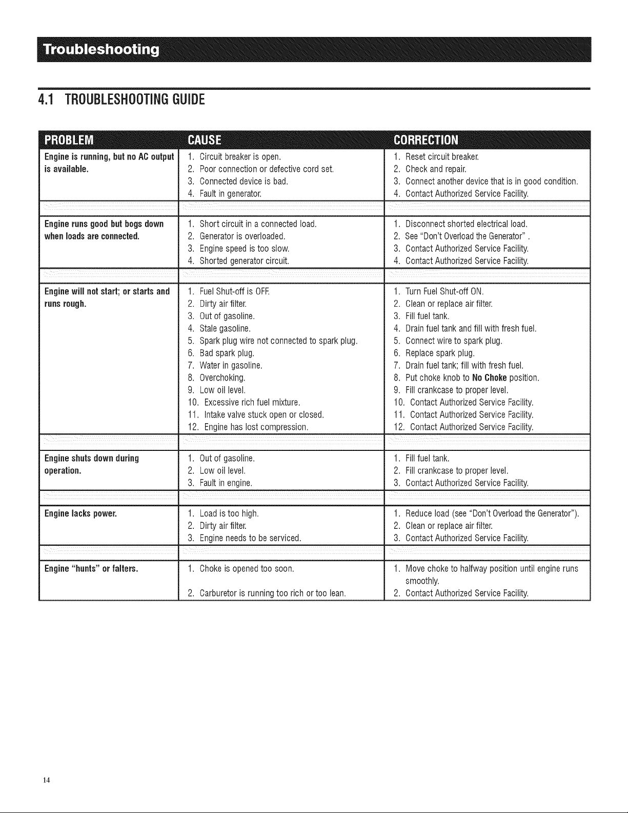
3.4 SERVICEAiRFILTER
Theenginewilt not run properlyand may be damagedif usinga
dirty airfilter. Cleanthe air filter every 200 hours or once a year
(Figure16). Cleanor replacemore often if operatingunderdusty
conditions.Theair filter part numberis 0G84420151.
• Removeairfilter cover.
• Washin soapy water.Squeezefilterdry in cleancloth (DONOT
TWIST).
• Cleanair filter cover beforere-installingit.
NOTE:
Toorder a new air filter, pleasecontactthe nearestauthorized
servicecenterat 1-888-GENERAC.
Figure 16- Air Filter
,_ CAUTION!
,_The NEGATIVE battery terminal should:
1. Always be DISCONNECTEDFIRST.
2. Alwaysbe CONNECTEDLAST.
12
CLIP_
3.5 VALVECLEARANCE
* Intake-- 0.15 __O.02mm (cold), (0.006" __0.0008" inches)
* Exhaust-- 0.20 _ O.02mm(cold) (0.008" _ 0.0008" inches)
Afterthefirst 50 hoursof operation,checkthevalveclearance
in the engineand adjustif necessary.
Important: If feelinguncomfortableabout doing this procedureor
theproper tools are not available,pleasetakethe generatorto the
nearestservicecenterto havethevalveclearanceadjusted.This is
a very importantstepto ensurelongestlife for theengine.
3.6 GENERAL
Thegeneratorshould be started at least once every 30 days and
be allowed to run at least 30 minutes. If this cannot be done and
the unit must be stored for morethan 30 days, use thefollowing
informationas a guideto prepareitfor storage.
NEVER store engine with fuel in tank indoors
or in enclosed, poorly ventilated areas where
fumes may reach an open flame, spark or pilot
light as on a furnace, water heater, clothes dryer
or other gas appliance.
,_AIIow unit to cool entirely before storage.
3.7 LONGTERMSTORAGE
It is importantto preventgum depositsfrom forming in essential
fuel systemparts such as the carburetor,fuel hose or tank during
storage. Also, experience indicates that alcohol-blended fuels
(called gasohol,ethanolor methanol)can attract moisture,which
leadsto separationandformation of acids during storage.Acidic
gascan damagethe fuel systemof an enginewhile in storage.
To avoid engine problems, the fuel system should be emptied
beforestorageof 30 daysor longer,asfollows:
Drain fuel into approved container outdoors,
away from open flame. Be sure engine is cool.
Do not smoke.
* Start and run engineuntil enginestops from lack of fuel.
* While engineis still warm, drain oil from crankcase. Refillwith
recommendedgrade.
* Removespark plugandpour about 1/2 ounce (15 ml) of engine
oil into the cylinders. Coverspark plug hole with rag. Puttthe
recoil starter a couple times to lubricatethe piston rings and
cylinder bore.
ACAUTION!
,_Avoid spray from spark plug hole when
cranking engine.
* Install andtighten spark plug.Donot connectspark plugwire.
* Cleanthe generatorouter surfaces. Checkthat cooling air slots
and openingson generatorareopen andunobstructed.
* Storethe unit in a clean, dry place.
3.8 OTHERSTORAGETiPS
* Do notstore gasolinefrom oneseasonto another.
* Replacethe gasolinecan if it startsto rust. Rustand/ordirt in
the gasolinewill cause problems with the carburetor and fuel
system.
* If possible,storethe unit indoorsandcover it to giveprotection
from dust anddirt. BESURETOEMPTYTIdEFUELTANK.
* If it is not practicalto empty the fuel tank and the unit is to be
storedfor sometime, useacommerciallyavailablefuelstabilizer
addedto the gasolineto increasethe life of thegasoline.
* Cover the unit with a suitable protective cover that does not
retainmoisture.
* Removeall gasolinefrom the fueltank.
,_ NEVER cover the generator while engine and
exhaust areas are warm.
13
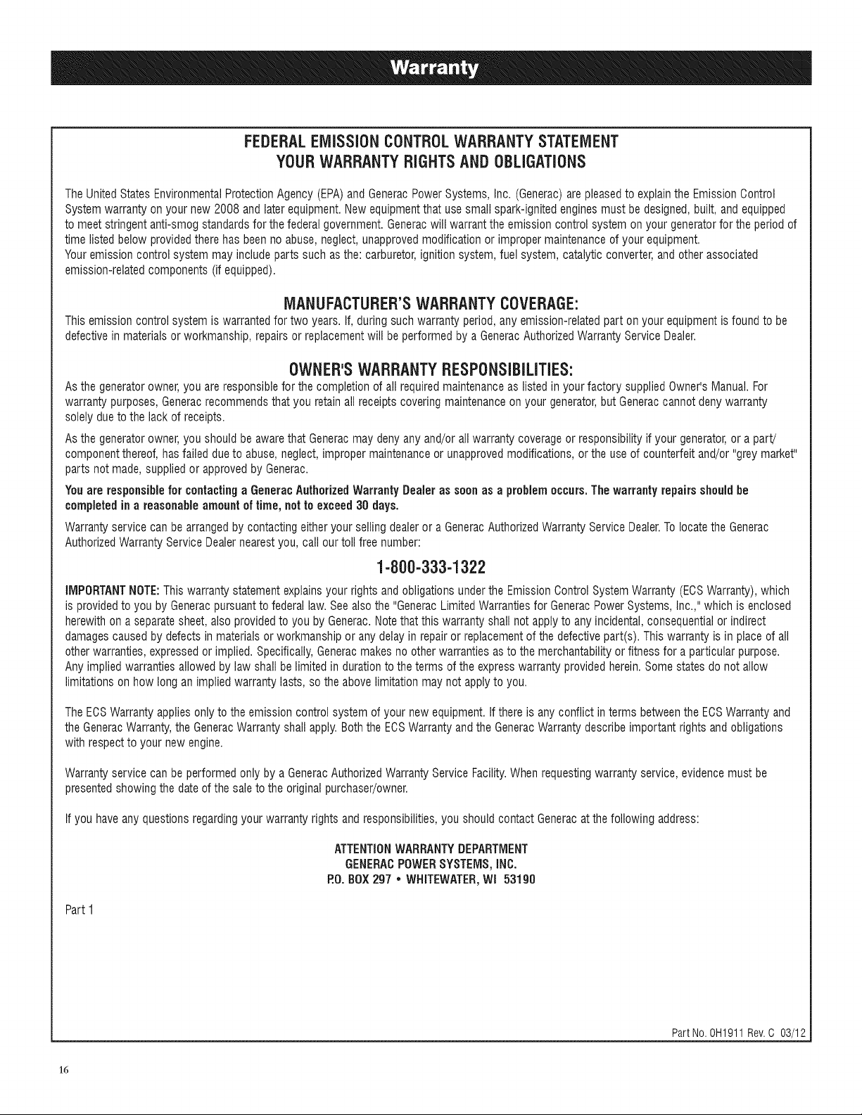
4.1 TROUBLESHOOTINGGUIDE
Engineis running,but no ACoutput
is available.
1. Circuit breakeris open.
2. Poorconnection or defectivecord set.
3. Connecteddevice is bad.
4. Faultin generator.
1. Resetcircuit breaker.
2. Checkand repair.
3. Connectanotherdevicethat is in good condition.
4. Contact AuthorizedService Facility.
Engine runs good but bogs down 1. Short circuit in a connectedload. 1. Disconnectshorted electricalload.
whenloadsare connected. 2. Generatoris overloaded. 2. See"Don'tOverloadtheGenerator".
3. Enginespeedis too slow. 3. ContactAuthorizedService Facility.
4. Shorted generatorcircuit. 4. Contact AuthorizedServiceFacility.
Enginewill notstart;orstartsand
runsrough.
FuelShut-offis OFF.
,
2.
Dirtyair filter.
3.
Out of gasoline.
4.
Stale gasoline.
5.
Sparkplug wire not connectedto sparkplug.
6. Badsparkplug.
7. Water in gasoline.
8. Overchoking.
9. Low oil level.
10. Excessiverich fuel mixture.
11. Intakevalvestuck open or closed.
12. Enginehas lost compression.
1. TurnFuelShut-off ON.
2. Cleanor replaceair filter.
3. Fillfuel tank.
4. Drainfuel tank and fill with fresh fuel.
5. Connectwire to spark plug.
6. Replacesparkplug.
7. Drainfuel tank;fill with freshfuel.
8. Put choke knobto NoChokeposition.
9. Fill crankcaseto proper level.
10. ContactAuthorizedServiceFacility.
11. ContactAuthorizedServiceFacility.
12. ContactAuthorizedServiceFacility.
Engineshuts down during 1. Out of gasoline. 1. Fillfuel tank.
operation. 2. Lowoil level. 2. Fill crankcaseto proper level.
3. Faultin engine. 3. ContactAuthorizedService Facility.
I I
Engine lacks power. 1. Loadis too high. 1. Reduceload (see"Don't Overloadthe Generator").
2. Dirty air filter. 2. Cleanor replaceair filter.
3. Engineneedsto be serviced. 3. ContactAuthorizedServiceFacility.
R
Engine "bunts" orfalters. 1. Chokeis openedtoo soon. 1. Movechoketo halfway position until engineruns
smoothly.
2. Carburetoris runningtoo rich or too lean. 2. ContactAuthorizedServiceFacility.
14

15
FEDERALEMiSSiONCONTROLWARRANTYSTATEMENT
YOURWARRANTYRIGHTSANDOBLiGATiONS
TheUnitedStates EnvironmentalProtectionAgency (EPA)andGeneracPowerSystems, Inc. (Generac)are pleasedto explainthe EmissionOontrol
Systemwarranty onyour new 2008 and later equipment.Newequipmentthat usesmall spark-ignitedenginesmust be designed,built, and equipped
to meetstringent anti-smog standardsfor the federalgovernment. Generacwill warrantthe emission control system on your generatorfor the period of
time listed below providedthere has been no abuse,neglect,unapprovedmodificationor improper maintenanceof your equipment.
Youremission control system may includeparts such as the: carburetor,ignitionsystem,fuel system,catalytic converter, andother associated
emission-relatedcomponents (if equipped).
MANUFACTURER'SWARRANTYCOVERAGE:
This emission control system is warrantedfor two years. If, during such warranty period,any emission-relatedpart on your equipmentis found to be
defectivein materials or workmanship,repairsor replacementwill beperformed by a GeneracAuthorizedWarrantyServiceDealer.
OWNER'SWARRANTYRESPONSiBiLiTiES:
Asthe generatorowner,you are responsiblefor the completion of all requiredmaintenanceas listed in your factory suppliedOwner'sManual.For
warrantypurposes, Generacrecommendsthat you retainall receipts covering maintenanceon your generator,but Generaccannot deny warranty
solelydueto the lack of receipts.
Asthe generatorowner,you should be awarethat Generacmay deny any and/orall warranty coverageor responsibilityif your generator,or a part!
componentthereof, hasfailed due to abuse,neglect, improper maintenanceor unapprovedmodifications,or the use of counterfeit and/or "grey market"
parts not made, suppliedor approvedby Generac.
Youare responsible for contactinga GeneracAuthorizedWarrantyDealer assoon as a problemoccurs.The warrantyrepairs should he
completed in a reasonable amount oftime, not to exceed 30 days.
Warrantyservice can be arrangedby contacting eitheryour sellingdealer or a GeneracAuthorizedWarrantyService Dealer.Tolocatethe Generac
AuthorizedWarrantyService Dealernearestyou, call our toll free number:
1-800-333-1322
IMPORTANTNOTE:Thiswarranty statementexplainsyour rightsand obligations underthe EmissionOontrolSystemWarranty(EOSWarranty),which
is providedto you by Generacpursuanttofederal law. See alsothe "GeneracLimitedWarrantiesfor GeneracPowerSystems, Inc.,"which is enclosed
herewith on aseparatesheet, also providedto you by Generac.Notethat this warrantyshall not applyto anyincidental,consequentialor indirect
damagescausedby defectsin materialsor workmanship or any delayin repairor replacementof the defectivepart(s). This warranty is in placeof all
other warranties,expressedor implied.Specifically,Generacmakes no otherwarranties as to the merchantabilityor fitness for aparticular purpose.
Any impliedwarrantiesallowedby law shall be limited in durationto theterms of the expresswarrantyprovidedherein. Some states do not allow
limitationson how long an implied warrantylasts, so the abovelimitationmay not applyto you.
TheEOSWarrantyapplies only to the emission control system of your new equipment.If thereis any conflict in terms betweenthe ECSWarranty and
the GeneracWarranty,the GeneracWarrantyshall apply.Both the EOSWarrantyandthe GeneracWarrantydescribe important rights and obligations
with respectto your new engine.
Warrantyservice can be performed only by a GeneracAuthorizedWarrantyService Facility.Whenrequestingwarranty service, evidencemust be
presentedshowing the dateof the saleto the original purchaser/owner.
If you haveany questions regardingyourwarranty rights and responsibilities,you should contact Generacat the following address:
ATTENTIONWARRANTYDEPARTMENT
GENERACPOWERSYSTEMS,iNC.
P.O.BOX297• WHITEWATER,Wl 53190
Part I
PartNo. 0H1911 Rev.C 03/12
16
 Loading...