

Page 1
Page 2

FOREWORD
This manual has been written and published by GENERAC
POWER SYSTEMS, INC. to aid our dealers’ mechanics, company service personnel and general consumers when servicing the products
described herein.
It is assumed that these personnel are familiar with the servicing
procedures for these products, or like or similar products, manufactured and marketed by GENERAC® POWER SYSTEMS, INC. It is also
assumed that they have been trained in the recommended servicing
procedures for these products, which includes the use of mechanics
hand tools and any special tools that might be required.
Proper service and repair is important to the safe, economical and
reliable operation of the products described herein. The troubleshooting, testing, service and repair procedures recommended by
GENERAC® POWER SYSTEMS, INC. and described in this manual are
effective methods of performing such operations. Some of these
operations or procedures may require the use of specialized equipment. Such equipment should be used when and as recommended.
We could not possibly know of and advise the service trade of all
conceivable procedures or methods by which a service might be performed, nor of any possible hazards and/or results of each procedure or method. We have not undertaken any such wide evaluation.
Therefore, anyone who uses a procedure or method not recommended by the manufacturer must first satisfy himself that neither
his safety, nor the product’s safety, will be endangered by the service or operating procedure selected.
®
All information, illustrations and specifications contained in this
manual are based on the latest product information available at the
time of publication. However, GENERAC® POWER SYSTEMS, INC.
reserves the right to change, alter or otherwise improve the product
at any time without prior notice.
Some components or assemblies of the product described in this
manual may not be considered repairable. Disassembly, repair and
reassembly of such components may not be included in this manual.
The engines described herein may be used to power a wide variety
of products. Service and repair instructions relating to any such
products are not covered in this manual. For information pertaining
to use of these engines with other products, refer to any owner’s or
service manuals pertaining to said products.
Page 3

TABLE OF CONTENTS
DIMENSIONS AND FEATURES ............................ 3-7
4-CYCLE ENGINE THEORY...................................... 8
SECTION 1: GENERAL ...................................... 9-12
PURPOSE AND SCOPE OF MANUAL ................................ 9
LARGE FRAME ENGINES .................................................. 9
LONG BLOCK .................................................................. 9
ENGINE I.D. NUMBER/SERIAL NUMBER ............................ 9
ENGINE CARE ................................................................ 10
Recommended Fuels .................................................. 10
Recommended Engine Oil .......................................... 10
Change Oil Filter ........................................................ 10
STORAGE INSTRUCTIONS .............................................. 10
TUNE-UP PROCEDURE .............................................. 10-11
OVERSIZE PARTS ............................................................ 12
SECTION 2: AIR CLEANERS AND CARBURETION 14-17
AIR CLEANER ................................................................ 14
Servicing .................................................................... 14
Foam Pre-Cleaner ...................................................... 14
Paper Filter ................................................................ 14
Air Cleaner Box Removal............................................ 14
Air Cleaner Box Installation ........................................ 15
CARBURETION .......................................................... 15-16
General...................................................................... 15
Common Carburetor Problems .................................. 15
Carburetor Removal .................................................. 15
Carburetor Disassembly ........................................ 15-16
Carburetor Cleaning and Inspection .......................... 16
Carburetor Reassembly .............................................. 16
Carburetor Installation .............................................. 16
CARBURETOR ADJUSTMENT .......................................... 17
Initial Adjustment ...................................................... 17
Final Adjustment........................................................ 17
SECTION 3: MECHANICAL GOVERNOR.......... 18-20
GOVERNOR OPERATION ................................................ 18
GOVERNOR INTERNAL PARTS ........................................ 18
GOVERNOR EXTERNAL PARTS .................................. 18-19
Without Automatic Idle Control ................................ 18
With Automatic Idle Control ...................................... 19
Removal of Governor External Parts .......................... 19
Installation of Governor External Parts ........................ 19
GOVERNOR GEAR SHAFT REPLACEMENT ...................... 19
Inspection .................................................................. 19
Removal .................................................................... 19
Installation ................................................................ 19
LINKAGE INSTALLATION ................................................ 20
GOVERNOR ADJUSTMENT ........................................ 20-21
Initial Adjustment ...................................................... 20
Running Adjustment ............................................ 20-21
SECTION 4: OPTIONAL IDLE CONTROL .......... 22-23
GENERAL ...................................................................... 22
OPERATING INSTRUCTIONS............................................ 22
Before Start-up .......................................................... 22
Engine Running.......................................................... 22
CIRCUIT OPERATION ...................................................... 22
IDLE CONTROL ADJUSTMENT .................................. 22-23
General...................................................................... 22
Initial Adjustment.................................................. 22-23
Final Adjustment........................................................ 23
SECTION 5: REWIND STARTERS...................... 24-25
GENERAL ...................................................................... 24
REWIND ASSEMBLY REMOVAL ...................................... 24
DISASSEMBLY (OLD STYLE) ............................................ 25
REASSEMBLY.................................................................. 25
DISASSEMBLY (NEW STYLE)............................................ 25
SECTION 6: ELECTRIC STARTERS AND BATTERIES ..26-28
INTRODUCTION ............................................................ 26
STARTER CONTACTOR SYSTEM...................................... 26
HEAVY DUTY SWITCH SYSTEM...................................... 26
STARTER MOTOR OPERATING PRINCIPLES...................... 26
THE BENDIX DRIVE ........................................................ 26
STARTER MOTOR REPAIRS ........................................ 26-27
Starter Motor Removal .............................................. 26
Starter Motor Installation ...................................... 26-27
TESTING THE STARTER MOTOR ...................................... 27
Checking the Pinion .................................................. 27
Tools for Starter Performance Test .............................. 27
Starter Performance Test ............................................ 27
BATTERY MAINTENANCE .............................................. 27
General...................................................................... 27
Inspecting the Battery ................................................ 27
Electrolyte Level ........................................................ 27
TESTING A BATTERY ................................................ 27-28
SECTION 7: COVERS AND SHROUDS .................. 29
GENERAL ...................................................................... 29
Installation of Covers and Shrouds ............................ 29
1
Page 4

TABLE OF CONTENTS
GENERAC
SECTION 8: IGNITION SYSTEM ...................... 30-31
GENERAL ...................................................................... 30
MAJOR COMPONENTS .................................................. 30
IGNITION COIL ASSEMBLY.............................................. 30
SPARK PLUG .................................................................. 30
FLYWHEEL ................................................................ 30-31
Checking Flywheel Magnet ........................................ 30
Flywheel Key.............................................................. 30
Flywheel Removal ................................................ 30-31
Flywheel Installation .................................................. 31
TESTING THE IGNITION SYSTEM .................................... 31
SECTION 9: VALVE TRAIN .............................. 32-36
MAJOR COMPONENTS .................................................. 32
DISASSEMBLY .......................................................... 32-33
VALVE SERVICE .............................................................. 33
Valves ........................................................................33
Valve Seats ................................................................ 33
Valve Tappets ............................................................ 34
Valve Springs.............................................................. 34
Valve Guides.............................................................. 34
INSTALLATION .......................................................... 34-35
ADJUSTING VALVE CLEARANCE .................................... 36
INSTALL ROCKER ARM COVER ........................................36
SECTION 10: PISTON, RINGS AND ROD ........ 38-41
GENERAL ...................................................................... 38
REMOVAL ...................................................................... 38
PISTON .................................................................... 38-39
Removal from Connecting Rod .................................. 38
Check Piston for Wear .......................................... 38-39
PISTON RINGS .......................................................... 39-40
General...................................................................... 39
Description .......................................................... 39-40
Ring End Gap ............................................................ 40
CONNECTING ROD ........................................................ 40
ASSEMBLY AND INSTALLATION ...................................... 41
Assembly .................................................................. 41
Installation ................................................................ 41
CYLINDER SERVICE ........................................................ 41
Inspection .................................................................. 41
Reboring the Cylinder ................................................ 41
SECTION 11: CRANKSHAFT, CAMSHAFT
AND BALANCER .............................................. 42-45
CRANKCASE COVER REMOVAL .................................... 42
CRANKSHAFT, CAMSHAFT AND BALANCER REMOVAL .. 42
BALANCER INSPECTION ................................................ 42
CAMSHAFT INSPECTION ................................................ 43
CRANKSHAFT INSPECTION........................................ 43-44
Crankshaft Proper...................................................... 43
Crankshaft Sleeve Bearing.......................................... 44
COMPRESSION RELEASE .......................................... 44-45
CRANKSHAFT INSTALLATION ........................................ 45
CAMSHAFT INSTALLATION ............................................ 45
BALANCER INSTALLATION .............................................. 45
SECTION 12: LUBRICATION ............................ 46-51
GENERAL ...................................................................... 46
OIL FLOW ...................................................................... 46
OIL PICKUP ASSEMBLY .............................................. 46-47
Description ................................................................ 46
Inspection .................................................................. 47
OIL PUMP ...................................................................... 47
Description ................................................................ 47
Inspection .................................................................. 47
PRESSURE RELIEF VALVE ................................................ 48
Description ................................................................ 48
Inspection .................................................................. 48
CRANKSHAFT OIL SEALS ................................................ 48
Description ................................................................ 48
Seal Replacement ...................................................... 48
BREATHER ASSEMBLY .................................................... 49
Description ................................................................ 49
Inspection .................................................................. 49
CRANKCASE COVER ................................................ 49-50
Description ................................................................ 49
Inspection .................................................................. 49
Governor Gear Installation ........................................ 49
Crankcase Cover Installation ................................ 49-50
OPTIONAL OIL FILTER...................................................... 51
LOW OIL PRESSURE SYSTEM .......................................... 51
SECTION 13: TROUBLESHOOTING ................ 52-54
SPECIFICATIONS .............................................. 55-61
2
Page 5
DIMENSIONS AND FEATURES
If you don't understand any portion of this manual, con-
tact an authorized Generac service dealer.
Throughout this publication, DANGER, WARNING and CAUTION blocks are used to alert you to special instruction about
a particular operation that may be hazardous if performed
incorrectly or carelessly. Observe them carefully.
These safety warnings cannot eliminate the hazards that
they indicate. Strict compliance with the special instructions
while performing the service plus "common sense" are major
measures to prevent accidents.
The following definitions apply to DANGER, WARNING,
CAUTION and NOTE blocks found throughout the manual.
DANGER: After this heading you can read handling, installing, operating or servicing instructions
that, if not strictly complied with, will result in personal injury.
WARNING: After this heading you can read handling, installing, operating or servicing instructions
that, if not strictly complied with, may result in personal injury.
In addition to the DANGER, WARNING, CAUTION and
NOTE blocks, the following blocks indicate specifications or
capacities as noted.
Indicates a fluid capacity.
Indicates a measurement.
Indicates a torque specification.
Indicates a load specification.
CAUTION: After this heading you can read instructions for handing, installing, operating or servicing
the engine that, if not strictly complied with, may
result in damage to equipment and/or property.
NOTE: After this heading you can read explanatory
statements that require special emphasis.
3
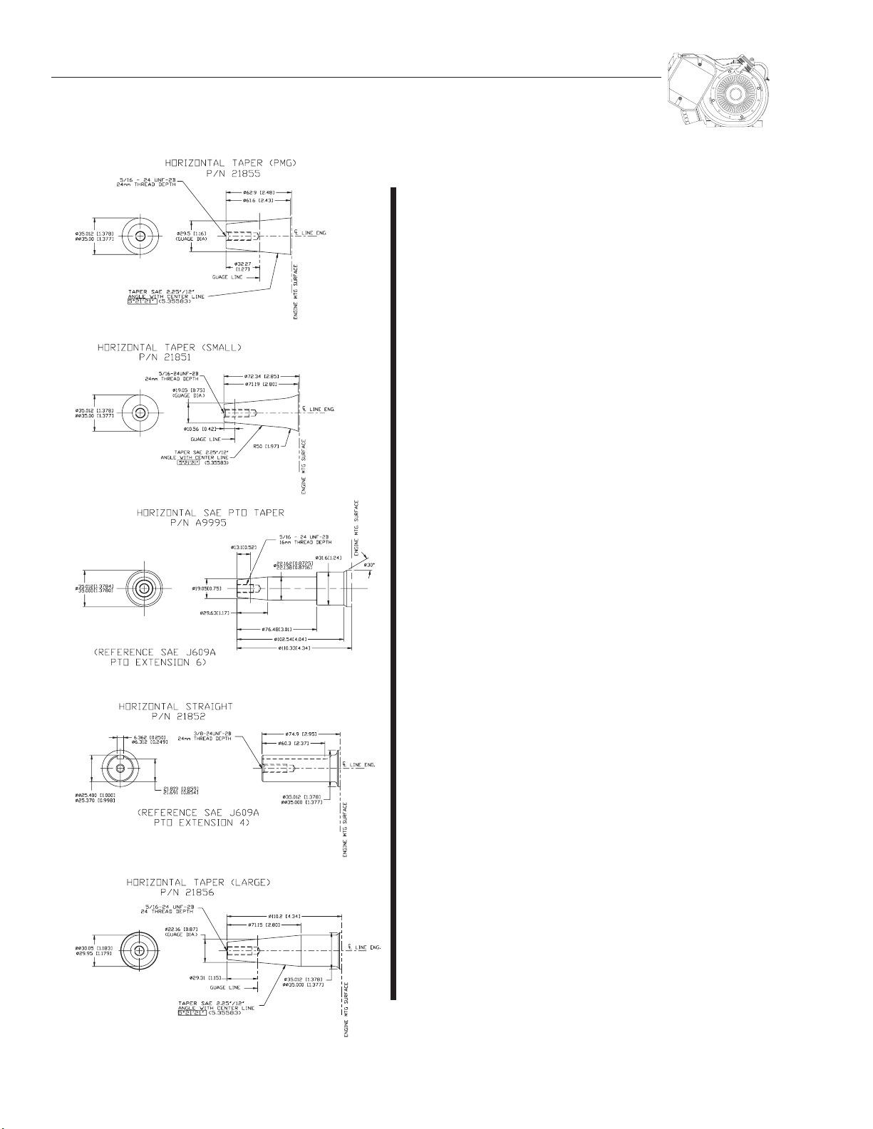
Page 6
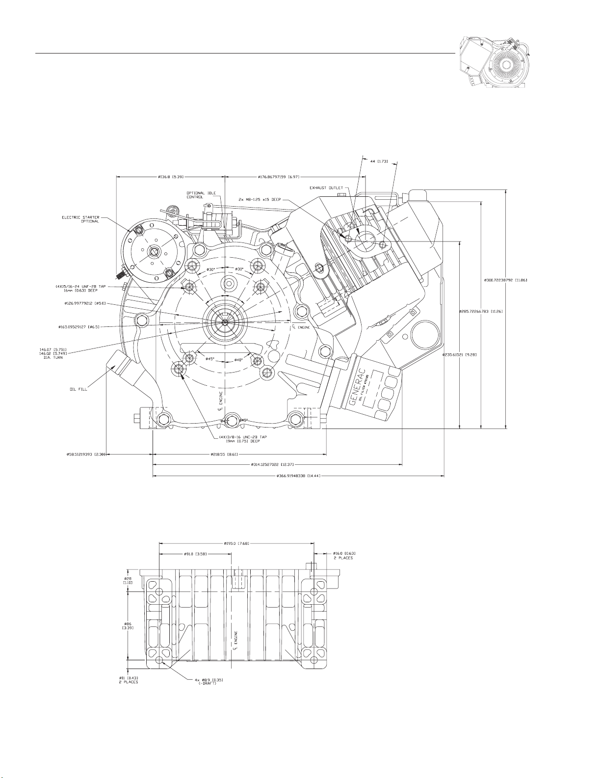
DIMENSIONS AND FEATURES
GENERAC
PTO SIDE VIEW
BOTTOM VIEW — MOUNTING HOLES
4
Page 7
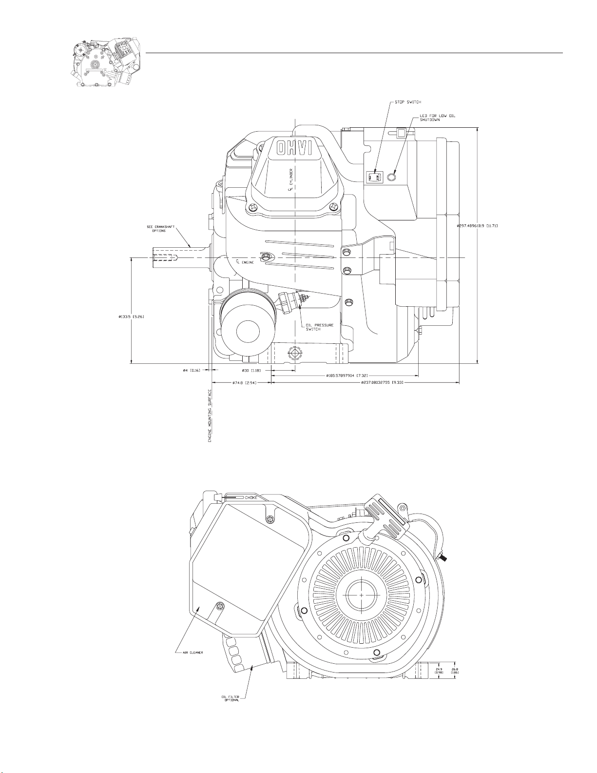
FRONT VIEW
DIMENSIONS AND FEATURES
STARTER SIDE VIEW
5
Page 8
DIMENSIONS AND FEATURES
GENERAC
PTO CRANKSHAFT OPTIONS VIEW
55. DOWEL PIN
56. DOWEL PIN
57. SPRING PIN
58. OIL PUMP INNER ROTOR SHAFT
59. CAMSHAFT GEAR
60. ROCKER ARM
61. COMPRESSION RELIEF SPRING
62. COMPRESSION RELIEF FLYWEIGHT
63. COMPRESSION RELIEF LIFT SHAFT
64. O-RING
65. VALVE SPRING RETAINER
66. VALVE SPRING KEEPER
67. EXHAUST VALVE
68. INTAKE VALVE
69. DOWEL PIN
70. VALVE SPRING WEAR WASHER
71. VALVE SPRING
37. CRANKSHAFT GEAR
38. CRANKSHAFT OIL SEAL
39. PIVOT BALL STUD
40. JAM NUT
41. CRANKSHAFT GEAR
42. OIL PRESSURE RELIEF SCREW
43. OIL FILL PLUG
44. TAPER PLUG
CUTAWAY VIEWS DESCRIPTIONS
19. OIL PUMP OUTER ROTOR
20. OIL PUMP INNER ROTOR
21. CYLINDER HEAD GASKET
22. CRANKCASE COVER BOLT
23. ROCKER ARM COVER GASKET
24. CYLINDER HEAD BOLT
25. DATA DECAL
26. OVERLAMINATE
45. TAPER PLUG
46. GOVERNOR GEAR THRUST WASHER
47. GOVERNOR FLYWEIGHT PIN
48. OIL PICKUP ASSEMBLY
49. GOVERNOR RETAINER CLIP
50. GOVERNOR ARM “R” PIN
51. GOVERNOR ARM THRUST WASHER
52. VALVE STEM SEAL
27. ROCKER ARM COVER SCREW
28. SPRING WASHER
29. OIL PRESSURE RELIEF VALVE SPRING
30. OIL PRESSURE RELIEF VALVE BALL
31. GOVERNOR SPOOL
32. GOVERNOR GEAR
33. GOVERNOR FLYWEIGHT
34. GOVERNOR SHAFT
53. OIL PRESSURE RELIEF RETAINER
54. PUSH ROD GUIDE PLATE
35. GOVERNOR ARM
36. PIPE PLUG
6
1. CRANKCASE
2. CRANKCASE COVER
3. ASSEMBLY
4. CRANKSHAFT
5. CAMSHAFT
6. ROCKER ARM COVER
7. CONNECTING ROD
8. PISTON RING TOP
9. PISTON RING, SECOND
10. OIL RING, RAIL
11. OIL RING, SPACER
12. BALANCER
13. CRANKCASE COVER GASKET
14. PISTON
15. PISTON PIN
16. SNAP RING
17. TAPPET
18. PUSH ROD
Page 9
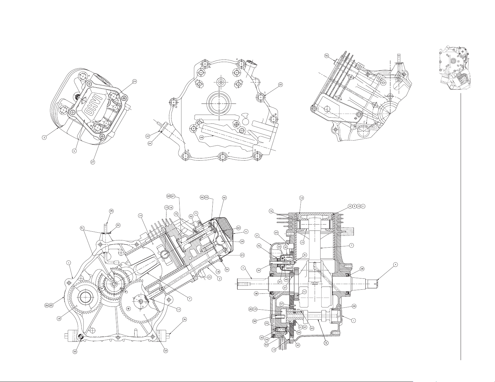
CUTAWAY VIEWS
7
DIMENSIONS AND FEATURES
Page 10
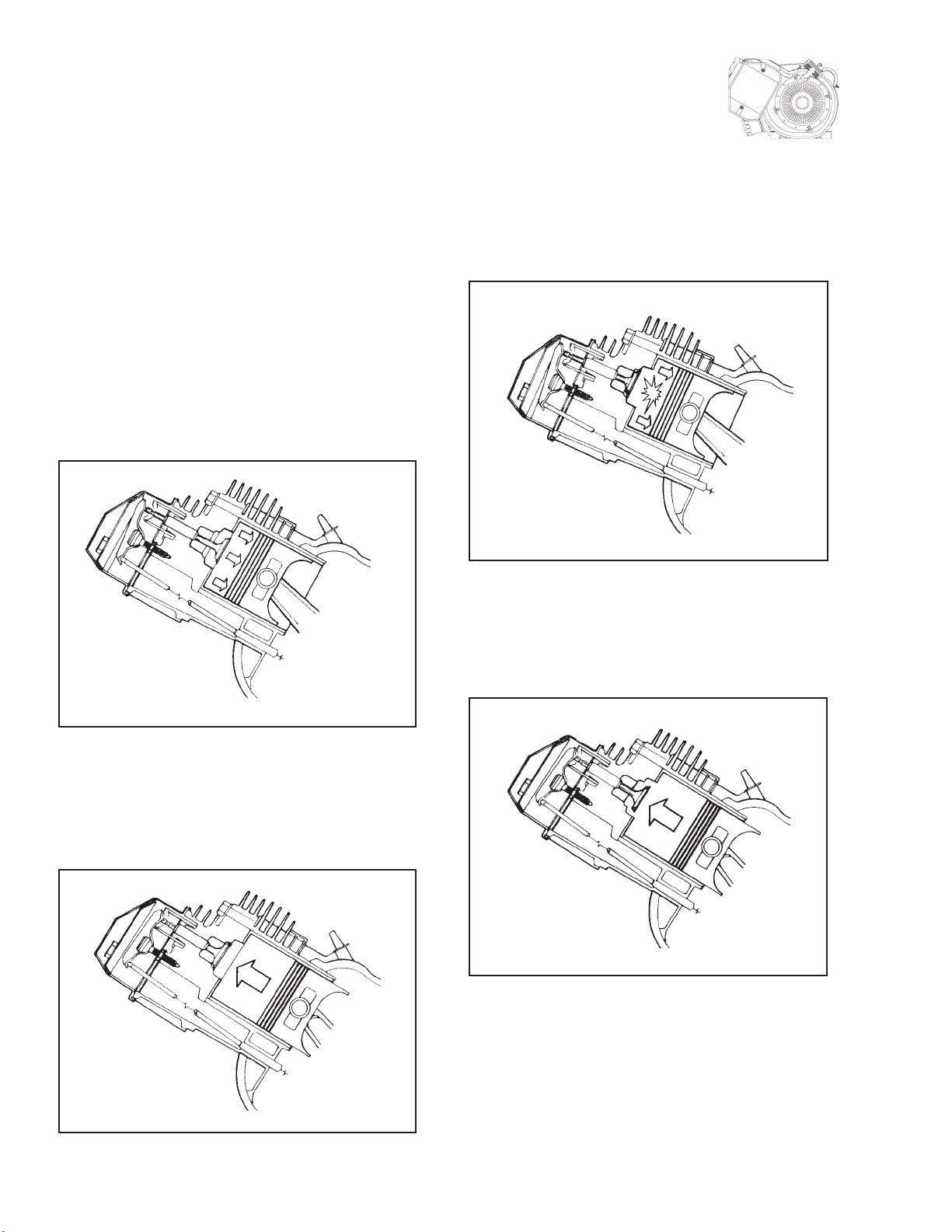
4-CYCLE ENGINE THEORY
GENERAC
If the engine Is to run properly, four (4) events must occur
in the proper sequence and at the correct time. These
events are (a) intake, (b) compression, (c) ignition and
power, and (d) exhaust.
A INTAKE
The piston is travelling from top dead center (TDC) to
bottom dead center (BDC). The cam has opened the intake
valve. The piston's downward movement in the cylinder
creates a partial vacuum In the cylinder. Air at atmospheric pressure is drawn into the cylinder through the
carburetor and is mixed with fuel in the carburetor. The
fuel-air mixture flows through the open intake valve into
the cylinder. When the piston reaches BDC, the intake
stroke is over.
IGNITION AND
C
By the time the piston reaches TDC, combustion is already
in progress. The intake and exhaust valves remain closed
as the expanding gases of combustion force the piston
downward.
POWER
D EXHAUST
The exhaust stroke begins when the piston has reached
BDC and has started its upward movement. The intake
valve is closed. The exhaust valve is open to let gases
escape.
B COMPRESSION
As the piston reaches bottom dead center (BDC), both the
intake and exhaust valves are closed. The piston moves
upward toward TDC and the fuel-air mixture is compressed. Just before the piston reaches TDC, ignition
occurs.
8
Page 11
PURPOSE AND SCOPE OF MANUAL
This manual contains all information normally required to
service or repair the Models GN-320, GN-360 and GN-410
horizontal shaft engines. Repair procedures are carefully
explained and illustrated.
LARGE FRAME ENGINES
Engine Models GN-320, GN-360 and GN-410 are designated as "large frame" engines. Some of the differences
between specific engine models are as follows:
1.Differences in the type of crankshaft.
a. Some engine models are equipped with a tapered crank-
shaft.
b. Some engine models may be equipped with a 1-inch
straight shaft.
2.Some engine models are equipped with automatic idle
control, other models are not.
3.Some engine models are equipped with an OPTIONAL oil
filter assembly.
4.Some engines may be equipped with electric start, others
are manual start.
5.Some engine models are "vertical shaft" for use in specific
applications (such as recreational vehicle generators).
6.Some engines are "horizontal shaft" type.
7.Some have an LOS (Low Oil Shutdown) module.
8.Some have an oil fill tube.
SECTION 1: GENERAL
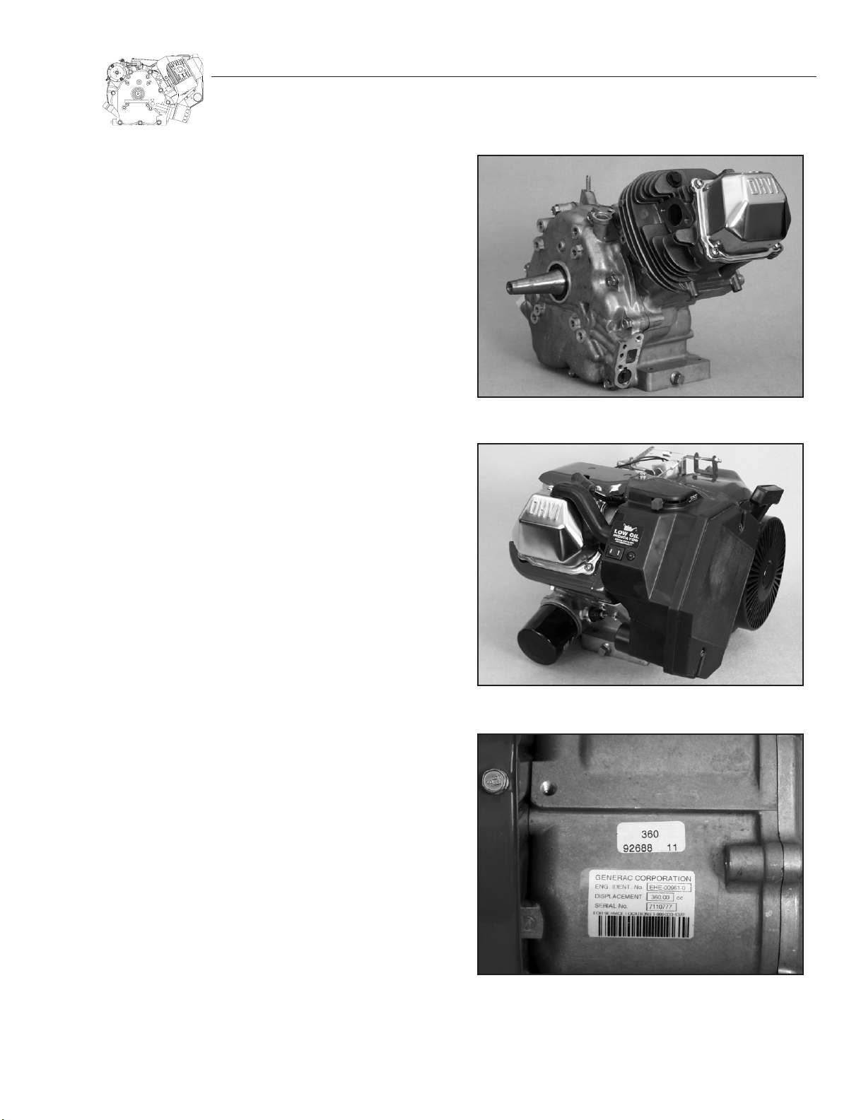
Figure 1.1 — Typical Long Block
LONG BLOCK
The term "long block" refers to a basic engine which does
not have such items as a blower housing, air cleaner, carburetor, etc. Figure 1.1 shows a typical long block.
Figure 1.2 shows a typical complete engine, with all the parts
needed to adapt the engine for a particular use. The typical
complete engine shown is a horizontal shaft model, for use
with AC generators.
ENGINE I.D. NUMBER/SERIAL NUMBER
The engine ID number and serial number of the engine long
block can be found on a nameplate, located on the engine
crankcase. (See Figure 1.3).
NOTE: Have the engine model and serial number when
ordering parts. This number is located on the back of
the cylinder block on the identification tag.
Figure 1.2 — Typical Complete Engine
Figure 1.3. — Location of Engine I.D. and Serial Numbers
9
Page 12
SECTION 1: GENERAL
GENERAC
ENGINE CARE
RECOMMENDED FUELS:
Use clean, fresh, UNLEADED regular grade gasoline.
Unleaded gasoline burns cleaner, extends engine life and
promotes easier starting by reducing combustion chamber
deposits.The use of gasohol is NOT recommended. If gasohol must be used, it should contain not more than 10 percent
ethanol. If gasohol containing ethanol is used, special care
is required when preparing the engine for storage (see "Storage Instructions").
• DO NOT USE GASOLINE CONTAINING METHANOL.
• DO NOT MIX OIL WITH THE GASOLINE.
DANGER! GASOLINE IS EXTREMELY FLAMMABLE
AND ITS VAPORS ARE EXPLOSIVE. DO NOT PERMIT
SMOKING, OPEN FLAME OR HEAT IN THE VICINITY
WHILE HANDLING GASOLINE. AVOID SPILL AGE
OF GASOLINE ON A HOT ENGINE. COMPLY WITH
ALL LAWS PERTAINING TO THE STORAGE AND
HANDLING OF GASOLINE.
RECOMMENDED ENGINE OIL:
Use a clean, high quality, detergent oil classified "For Service SC, SD, SE, SF or SG." No special additives should be used
with the recommended oil. Detergent oils keep the engine
cleaner and retard the formation of gum and varnish deposit.
Synthetic oil can be used in place of petroleum base oils.
During summer months (above 32F or 0C), use SAE 30 oil.
SAE 10W-30 oil is an acceptable substitute.
During winter (below 32F or 0C) use SAE 5W-20 or 5W30 oil.
DO NOT USE SAE 10W-4O OIL.
CRANKCASE OIL CAPACITY
GN-320, GN-360, GN-410 ENGINES
WITHOUT OIL FILTER CHANGE —
46 ounces (1350 ml)
WITH OIL FILTER CHANGE —
51 ounces (1500 ml)
CHANGE OIL FILTER:
Replace oil filter with every oil change. Before installing new
oil filter, put a light coat of clean oil on rubber o-ring on filter
base. Screw filter on by hand until o-ring touches filter
adapter base, then tighten 3/4 turn. Check for leaks after starting engine.
Check engine oil level each time the equipment is used.
When checking oil level, make sure the equipment is level .
Change oil after the first eight hours of operation on a new
engine. Thereafter, change oil and filter every 50 hours of
operation. Change oil ever
y 25 hours if operating under
extremely dusty or dirty conditions, or in very hot weather.
NOTE: Engine may be equipped with automatic low oil
shutdown capability. If so equipped, it will not start
when oil level is low. See Section 12, "Lubrication."
STORAGE INSTRUCTIONS
The engine should be started at least once every seven days
and allowed to run for at least 30 minutes. If this cannot be
done and the engine is to remain unused longer than 30 days,
it must be prepared for storage.
DANGER! NEVER STORE THE ENGINE WITH FUEL IN
TANK INDOORS OR IN ANY ENCLOSED, POORLY
VENTILATED AREA WHERE FUEL VAPORS MIGHT
REACH AN OPEN FLAME (AS ON A FURNACE,
WATER HEATER, DRYER, ETC.). FIRE OR AN EXPLOSION COULD RESULT.
To prepare an engine for storage, proceed as follows:
1.Run the engine for about five minutes to warm it up.
a. If gasohol was used, drain the fuel tank, then run the
engine until it shuts down due to lack of fuel.
b. Use of a good fuel stabilizer will prevent gum deposits
from forming in the engine fuel system.
2.While engine is still warm from running, drain oil from
crankcase and refill with new oil.
3.Remove the spark plug and pour about 1/2 ounce (15ml)
of clean, fresh engine oil into cylinder. Crank the engine
over slowly to distribute the oil. Then, install the spark plug
but do not connect the spark plug wire.
4.Clean dirt, oil, grease, etc., from the engine.
5.Store the engine in a clean, dry area.
TUNE-UP PROCEDURE
Following is a minor tune-up procedure. When the procedure has been completed, either the engine will run properly
or further repairs may be required.
1.Service or replace engine air cleaner as needed.
2.Check level and condition of oil. Add or change oil
as necessary.
3. Remove the blower housing. Clean dirt from intake screen,
head and cylinder cooling fins. Also, remove dirt from carburetor and governor lever(s) and linkage.
4.Clean fuel tank, fuel filter(s) and fuel lines.
5.Replace any damaged governor springs.
6.If required, adjust the carburetor and governor.
10
Page 13
SECTION 1: GENERAL
7.Replace the spark plug. Use a Champion RC12YC (or
equivalent) spark plug.
a. Set spark plug gap to 0.030 inch (0.76mm).
b. Install new plug, tighten to 13 ft-lbs (156 in-lbs).
c. If torque wrench is not available, tighten plug with fin-
gers. Then, tighten NEW plug 1/2 turn further; or USED
plug 1/4 turn further.
8.Check that ignition wires are free of breaks and abrasions
and are properly routed.
9.Install the blower housing.
10. Run engine and adjust engine speed.
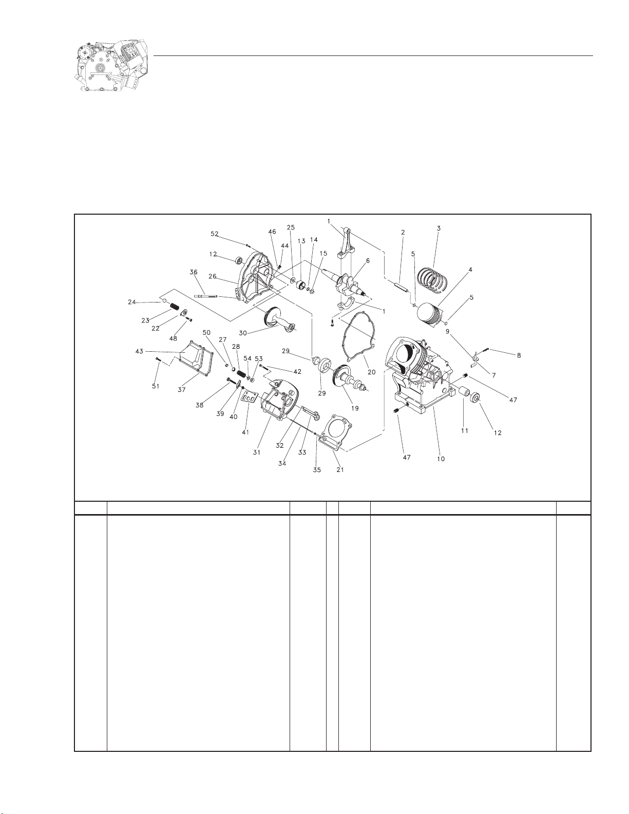
Figure 1.4 — Exploded View — Typical Horizontal Shaft Long Block
ITEM DESCRIPTION QTY ITEM DESCRIPTION QTY
1 Connecting Rod Assembly 1
2 Piston Pin 1
3 Piston Ring Set 1
4 Piston 1
5 Snap Ring 2
6 Crankshaft Assembly 1
7 Governor Arm 1
8 Governor Arm “R” Pin 1
9 Governor Arm Washer 1
10 Crankcase Assembly 1
11 Sleeve Bearing 1
12 Crankshaft Oil Seal 2
13 Governor Gear Assembly 1
14 Governor Gear Retainer 1
15 Governor Spool 1
19 Camshaft Assembly 1
20 Crankcase Gasket 1
21 Cylinder Head Gasket 1
22 Oil Pressure Relief Retainer 1
23 Oil Pressure Relief Spring 1
24 Oil Pressure Relief Ball 1
25 Governor Thrust Washer 1
26 Crankcase Cover 1
27 Valve Spring Retainer 2
28 Valve Spring 2
29 Gerotor Set 1
30 Balancer 1
31 Cylinder Head Assembly 1
32 Exhaust Valve 1
33 Intake Valve 1
34 Push Rod 2
35 Tappet 2
36 Oil Pick-up Assembly 1
37 Rocker Cover Gasket 1
38 Pivot Ball Stud 2
39 Rocker Arm 2
40 Rocker Arm Jam Nut 2
41 Push Rod Guide Plate 1
42 Cylinder Head Bolt 4
43 Rocker Cover/Breather Assembly 1
44 Oil Fill Plug 1
46 “O” ring 1
47 Pipe Plug 2
48 Oil Pressure Relief Screw 1
50 Valve Spring Keeper 4
51 Rocker Cover Screw 4
52 Crankcase Cover Bolt 8
53 Valve Stem Seal 1
54 Valve Spring Wear Washer 2
11
Page 14

SECTION 1: GENERAL
GENERAC
OVERSIZE PARTS
GENERAL:
At the time this Manual was published, oversize pistons,
rings, valves, etc., were not available. Worn or damaged
parts must be replaced.
OVERSIZE PISTONS AND RINGS:
Oversize pistons and rings are not available at this time. The
engine cylinder cannot be rebored to an oversize dimension.
If the cylinder is worn excessively or damaged, the crankcase
must be replaced. A standard size piston and rings can then
be used.
OVERSIZE VALVES:
Oversize valves are not available at this time. Valve guides
cannot be rebored to an oversize dimension. If valve guides
are worn or damaged, the cylinder head must be replaced.
Standard size valves can then be used. Valve guides cannot
be replaced.
NOTE: Always use original GENERAC® replacement
parts.
12
Page 15
SECTION 2: AIR CLEANERS AND CARBURETION
AIR CLEANER
SERVICING:
The engine will not run properly and may be damaged if it
is run with a dirty air cleaner.
Clean or replace the paper filter every 25 hours of operation or once annually, whichever occurs first. Clean or replace
the paper filter more often if operating in extremely dusty or
dirty conditions.
Clean or replace the foam pre-cleaner every 25 hours of
operation; more frequently under dirty or dusty conditions.
FOAM PRE-CLEANER:
To clean or replace the foam pre-cleaner:
1.Remove the air cleaner cover, then remove the foam pre-
cleaner.
2.Wash the foam pre-cleaner in soapy water.
3. Squeeze the pre-cleaner dry with a clean cloth. DO NOT
TWIST.
NOTE: If the pre-cleaner is still dirty after washing and
drying it, replace it with a new filter
4.Apply enough clean engine oil to saturate the pre-cleaner.
5.Wrap the pre-cleaner in a clean dry cloth and squeeze out
excess oil. DO NOT TWIST. Set the pre-cleaner aside.
4.Clean the paper filter by tapping gently on a flat surface.
If it is very dirty, replace it.
5.Clean the air cleaner cover. Then, install the foam precleaner into the cover.
6.Insert the paper filter into the cover so it holds the precleaner in place.
7.Assemble the pre-cleaner, paper filter and cover to the air
cleaner base.
AIR CLEANER BOX REMOVAL:
If the air cleaner box must be removed for further engine
disassembly, do the following (see Figure 2.2):
1.Remove the air cleaner cover.
2.Remove the foam pre-cleaner and paper filter.
3. Remove the choke knob.
4.Remove the breather hose.
5. Remove the two nuts and corresponding washers from the
carburetor mounting bolts.
6.Remove the two capscrews and corresponding washers
from the lower part of the air cleaner box.
NOTE: The carburetor will be loose after removal of the
air cleaner box. Do not allow the carburetor to drop.
Note: Be careful not to stretch or bind the wires connected to the Low Oil Indicator and Start/Stop switch.
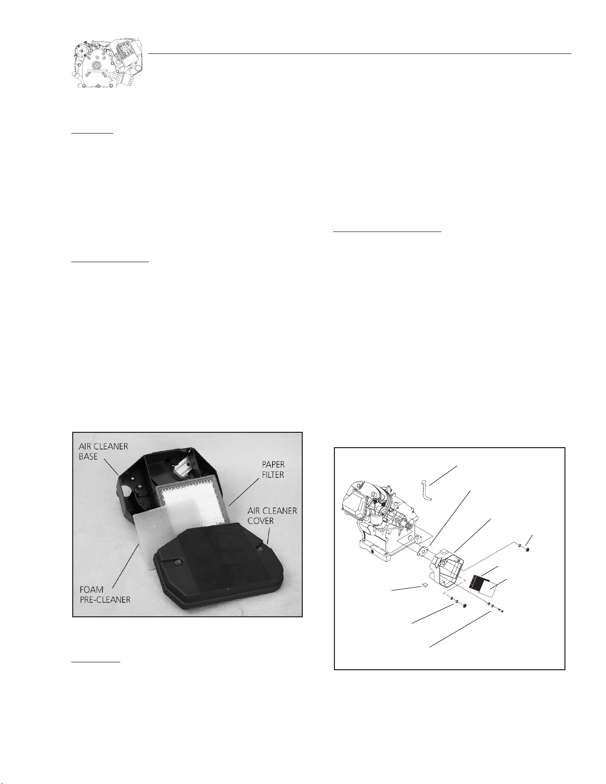
Figure 2.1. Typical Air Cleaner
APER FILTER:
P
1.Remove the air cleaner cover.
2.Remove the foam pre-cleaner and service it, if necessary.
3.Remove the paper filter.
13
BREATHER HOSE
GASKET
AIR CLEANER BOX
NUT AND WASHER
PAPER FILTER
FOAM
CHOKE KNOB
NUT, WASHER
AND LOCK WASHER
CAPSCREW
AND WASHERS
PRE-CLEANER
Figure 2.2 — Exploded View of Air Cleaner Box
Page 16
SECTION 2: AIR CLEANERS AND CARBURETION
GENERAC
AIR CLEANER BOX INSTALLATION:
Install the air cleaner box to the engine and carburetor as
follows:
1.Using a new gasket, place the air cleaner box on the carburetor, line up the holes and install the two nuts and
corresponding washers to the carburetor mounting bolts
(see Figure 2.2). Refer to “Torque Specifications” on page
59 for proper torque.
Note: The nut on the right side (toward the rear of the
engine) uses only a flat washer. The nut on the left side
(toward the front of the engine) uses a lock washer and
a flat washer (see Figure 2.2).
2. Install the two capscrews in the lower part of the air cleaner
box (see Figure 2.2). Refer to Torque Specifications on page
61 for proper torque.
3.Reinstall the breather hose.
4. Reinstall the choke knob.
5. Install the filters and cover as stated in the preceding sections
on filter maintenance.
CARBURETION
GENERAL:
Proper engine performance depends on the carburetion
system. The use of clean, fresh fuel and a well maintained
air cleaner is extremely important to engine operation, as well
as engine reliability and power.
COMMON CARBURETOR PROBLEMS:
Most causes of carburetor problems are related to the use
of stale, gummy fuel and the ingestion of dirt. Prior to servicing any carburetor, be sure to check for evidence of these
conditions.
Gasoline that is left in the system for long periods can form
gum or varnish deposits that will adversely affect carburetor
operation.
NOTE: Use of a good fuel stabilizer will minimize the
formation of gum deposits during storage. Add the
stabilizer to the gasoline in the fuel tank or in the storage container. Follow the mix ratio recommended on
the stabilizer container. After adding the stabilizer to
the engine fuel tank, run the engine for about ten (10)
minutes so it will enter the carburetor. A brand name
stabilizer can be purchased in most automotive repair
facilities or in lawn and garden centers.
SERVICE TIP:
Carefully inspect the carburetor choke and throttle shafts
for wear. Grasp each shaft and attempt to move it horizontally and vertically. Maximum allowable end play for choke
and throttle shafts is 0.004 inch (0.1mm). Replace if excessive play is evident.
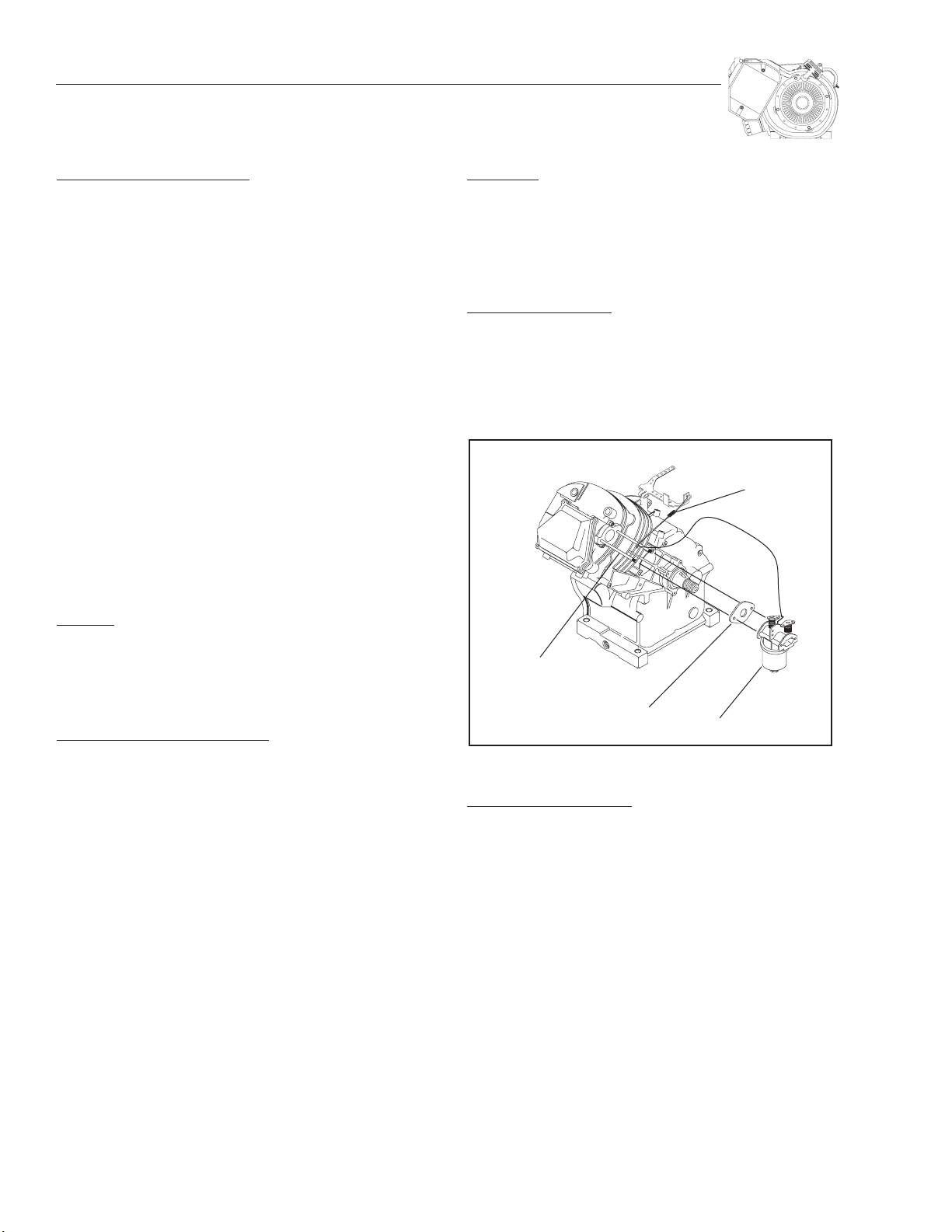
CARBURETOR REMOVAL:
1.Remove the air cleaner box as outlined in “AIR CLEANER
BOX REMOVAL.”
2.Disconnect the governor rod and anti-lash spring from the
throttle arm of the carburetor.
3.Slide the carburetor off of its mounting bolts.
GOVERNOR
ROD AND
ANTI-LASH SPRING
CARBURETOR
MOUNTING
BOLT
CARBURETOR
GASKET
CARBURETOR
Figure 2.3 — Removal of Carburetor
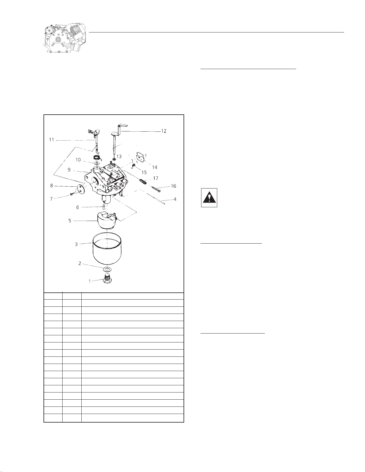
CARBURETOR DISASSEMBL
Y:
To disassemble the carburetor, proceed as follows (See
Figure 2.4):
1.Remove the FLOAT BOWL NUT (Item 1) and the FIBER
WASHER (Item 2). Then remove the FLOAT BOWL (Item 3).
2.Remove the FLOAT PIN (Item 4). Then remove the FLOAT
(Item 5), and FUEL INLET VALVE (Item 6).
3.Remove the IDLE SPEED STOP SCREW (Item 16) along with
its SPRING (Item 17).
4.Rotate the THROTTLE PLATE (Item 8) to it's closed position
and remove two THROTTLE PLATE SCREWS (Item 7).
14
Page 17
SECTION 2: AIR CLEANERS AND CARBURETION
5.Rotate the CHOKE PLATE (Item 14) to its closed position
and remove the CHOKE RETAINER SPRING (Item 15).
6.Remove the CHOKE SHAFT (Item 12) and the CHOKE
SHAFT SEAL (Item 13).
7.Remove the THROTTLE SHAFT (Item 11) and the THROTTLE SHAFT SEAL (Item 10).
CARBURETOR CLEANING AND INSPECTION:
1.Separate out all nonmetallic parts. Then, clean metallic
parts with solvent or commercial carburetor cleaner. DO
NOT PERMIT NONMETALLIC PARTS TO CONTACT SOLVENT OR CLEANER.
2.Inspect the THROTTLE SHAFT (Item 11) Replace if worn or
damaged.
3. Inspect the CHOKE SHAFT (Item 12) Replace if worn or damaged.
4.Inspect the FLOAT BOWL (Item 3). It must be free of dirt
and corrosion.
5.Inspect the FLOAT (Item 5) Replace if damaged.
6.After all metallic parts have been cleaned, blow out carburetor passages with compressed air.
Generac recognizes that there are spray type carburetor cleaners on the market, however Generac
does not authorize the use of carburetor cleaners.
Also, Generac does not recommend soaking a carburetor in any cleaners since the carburetor might
be damaged.
ITEM QTY DESCRIPTION
1 1 Float Bowl Nut
2 1 Fiber Washer
3 1 Float Bowl
4 1 Float Pin
5 1 Float
6 1 Fuel Inlet Valve
7 2 Throttle Plate Screw
8 1 Throttle Plate
9 1 Carburetor Body
10 1 Throttle Shaft Seal
11 1 Throttle Shaft
12 1 Choke Shaft
13 1 Choke Shaft Seal
14 1 Choke Plate
15 1 Choke Retainer Spring
16 1 Idle Speed Stop Screw
17 1 Spring
Figure 2.4 — Exploded View of Carburetor
CARBURETOR REASSEMBLY:
Reassemble the carburetor in the reverse order of disas-
sembly. The following rules apply:
1.Blow metallic parts dry with compressed air.
2.A notch on the FUEL INLET VALVE mates with the FLOAT
(See Figure 2.4).
3.The FLOAT SETTING is FIXED and NONADJUSTABLE.
4. Before tightening the FLOAT BOWL NUT (Item 1), make sure
the FLOAT BOWL is properly aligned with the GASKET and
the CARBURETOR BODY.
CARBURETOR INST
ALLATION:
Using a new gasket, reinstall the carburetor as follows:
1. Slide the new carburetor gasket over the carburetor mounting bolts followed by the carburetor.
2.Connect the governor rod and anti-lash spring.
3.Install the air cleaner box, filters and air cleaner cover as
described in “AIR CLEANER BOX INSTALLATION.”
15
Page 18
SECTION 2: AIR CLEANERS AND CARBURETION
GENERAC
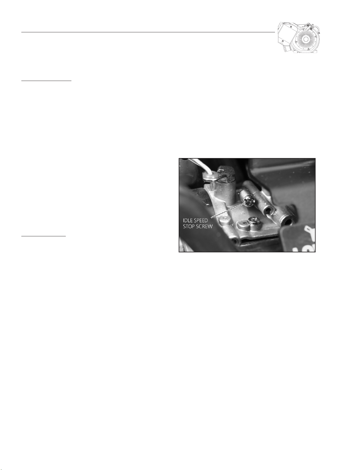
CARBURETOR ADJUSTMENT
INITIAL ADJUSTMENTS:
(See Figures 2.4 and 2.5)
1.The IDLE SPEED STOP SCREW is located at top of the carburetor and contacts the THROTTLE SHAFT. After
reassembling the carburetor, complete an initial adjustment of the STOP SCREW as follows:
a. Close the THROTTLE PLATE.
b. Hold the throttle plate in its closed position and back out
the idle speed stop screw.
c. Turn the idle speed stop screw until it just contacts the
stop tang of the throttle shaft. Then turn the idle speed
stop screw in one turn further.
NOTE: Final adjustment of idle speed can be accomplished with the engine running. Engines equipped with
optional automatic idle control require a special procedure for idle speed adjustment. See Section 4,
"Optional Idle Control."
NOTE: The carburetor is equipped with a fixed main jet,
which requires no adjustment.
FINAL ADJUSTMENT:
The following instructions apply to engines NOT equipped
with automatic idle control. If the unit has an automatic idle
control, refer to the Section 4, "Optional Idle Control."
If the engine is used to drive an AC generator set, use an
AC frequency meter to measure engine speed/frequency.
Connect the AC frequency meter across one of the generator’s AC output receptacles or across the generator’s AC
power winding output leads. Read the AC output frequency
in HERTZ (cycles per second).
If the engine is used in some other application (pressure
washer, pump, air compressor, etc.), use a tachometer to read
the engine rpm.
1.Start the engine and allow a sufficient warm-up period.
2. Hold the carburetor throttle lever against the idle speed stop
screw, then turn the idle speed stop screw until the correct idle speed is obtained.
a. If the driven unit is an AC generator and an AC frequency
meter is used, the correct idle speed is between 62-63
Hertz. (3720-3780 rpm).
b. If the unit is not a generator, adjust the idle speed stop
screw to obtain about 3750 rpm.
Figure 2.5 — Idle Speed Stop Screw
16
Page 19

NOTES
17
Page 20

SECTION 3: MECHANICAL GOVERNOR
GENERAC
GOVERNOR OPERATION
1.The GOVERNOR SPRING tends to pull the LEVER and GOVERNOR ROD toward the "INC. RPM" direction.
2. As engine speed increases, centripetal force acts on the FLYWEIGHT. When FLYWEIGHT centripetal force exceeds
SPRING force, the governor SPOOL is moved axially by FLYWEIGHT force. This causes the GOVERNOR ARM to rotate,
which then moves the LEVER and GOVERNOR ROD toward
a "DEC. RPM" direction.
3.As engine speed decreases, a point is reached where governor SPRING force is greater than FLYWEIGHT centripetal
force. SPRING force then moves the LEVER and GOVERNOR
ROD toward "INC. RPM."
4. Governor action consists of a series of small rpm overshoots
and undershoots, as SPRING force increases rpm and FLYWEIGHT centripetal force decreases rpm.
5.The point at which SPRING tension and FLYWEIGHT force
are equal is the governed speed of the engine.
SPEED
ADJUST
INC. RPM
CENTRIPETAL
FORCE
FLYWEIGHT
CRANKSHAFT
(PTO END)
SHAFT
GOVERNOR
GEAR
SPRING
TO THROTTLE LINK
DEC. RPM
SPOOL
CRANKSHAFT
GEAR
GOVERNOR
GEAR SHAFT
THRUST
WASHER
GOVERNOR
GEAR ASSEMBLY
LOCK PIN
SNAP
RING
WASHER
GOVERNOR
SPOOL
GOVERNOR
ARM
Figure 3.2 — Internal Governor Parts
GOVERNOR EXTERNAL PARTS
WITHOUT AUTOMATIC IDLE CONTROL:
External governor parts for units without automatic idle control are shown in Figure 3.3. Parts include (a) a GOVERNOR
LEVER, (b) a GOVERNOR ROD, (c) ANTI-LASH SPRING, (d) a
SPEED ADJUST BOLT, (e) a SPEED ADJUST NUT, and (f) a
GOVERNOR SPRING.
The governor lever is clamped to the governor arm, so that
arm rotation is imparted to the lever. The governor rod connects to the governor lever at one end and to the carburetor
throttle arm at it's other end. Governor spring tension is
adjustable by means of the speed adjust bolt and nut.
Engine speed can be adjusted by changing the tension of
the governor spring. Governor spring tension can be changed
by turning a locknut on the governor adjusting bolt.
Figure 3.1 — Governor Operating Diagram
GOVERNOR INTERNAL PARTS
See Figure 3.2. A governor gear shaft is pressed into a bore
in the engine crankcase cover. Internal governor components
include (a) a THRUST WASHER, (b) GOVERNOR GEAR ASSEMBLY, (c) SNAP RING, (d) GOVERNOR SPOOL, and (e) GOVERNOR
ARM. A lock pin and washer retain the governor arm in the
crankcase cover.
The governor gear assembly houses the governor flyweights.
Flyweight movement causes the spool to move axially. In
turn, axial movement of the spool results in rotation of the
governor arm.
Figure 3.3 — External Governor Parts
(Units without Idle Control)
18
Page 21

SECTION 3: MECHANICAL GOVERNOR
WITH AUTOMATIC IDLE CONTROL:
Models equipped with automatic idle control (Section 4)
have the same external governor parts as shown in Figure
3.3 with the addition of an idle control solenoid as shown
in Figure 3.4.
Figure 3.4 — External Governor Parts
(Units with Idle Control)
4. Reinstall the GOVERNOR SPRING to the GOVERNOR LEVER
and SPEED ADJUST SCREW, then tighten the SPEED ADJUST
NUT accordingly.
5. Reinstall the CAPSCREW into the IDLE CONTROL BRACKET
if equipped with automatic idle control (Figure 3.4). See
BLOWER HOUSING SCREW under “TORQUE SPECIFICATIONS,” page 61, for proper tightness.
For proper governor adjustment, refer to “GOVERNOR
ADJUSTMENT” on this page.
GOVERNOR GEAR SHAFT REPLACEMENT
CAUTION! DO NOT TWIST THE GEAR SHAFT WITH
A VISE GRIP OR ANY OTHER TOOL. THIS COULD
RESULT IN ENLARGEMENT OF THE SHAFT BOSS.
INSPECTION:
If the governor gear shaft is scored, damaged or worn, it
should be replaced.
GOVERNOR GEAR SHAFT DIAMETER
GN-320, GN-360, GN-410
0.236-0.237 inch (6.004-6.012mm)
AL OF GOVERNOR EXTERNAL PARTS:
REMOV
Before any covers and shrouds can be removed from the
engine, the governor external parts must be removed. Refer
to Figures 3.3 and 3.4 for identification of the parts described
in the following procedure.
1. Remove the CAPSCREW from the IDLE CONTROL BRACKET
if equipped with automatic idle control (Figure 3.4).
2.Loosen the GOVERNOR LEVER CLAMP BOLT (Figure 3.3).
3.Loosen SPEED ADJUST NUT until the GOVERNOR SPRING
can be removed (Figure 3.3).
4.Lift the GOVERNOR LEVER from the GOVERNOR ARM
(Figure 3.3).
5.Disconnect the GOVERNOR ROD and ANTI-LASH SPRING
from the GOVERNOR LEVER (Figure 3.3).
Set the governor external parts aside.
INSTALLATION OF GOVERNOR EXTERNAL PARTS:
AFTER the installation of the engine shrouds and covers,
reinstall the governor external parts as follows (refer to
Figure 3.3):
1.Reattach the GOVERNOR ROD and ANTI-LASH SPRING to
the GOVERNOR LEVER.
2.Slide the GOVERNOR LEVER onto the GOVERNOR ARM.
3. Tighten the GOVERNOR LEVER CLAMP BOLT.
REMOVAL:
If it becomes necessary to replace the governor gear shaft,
remove the crankcase cover (See Section 11). Use care to avoid
damage to the shaft boss area of the crankcase cover. Clamp
the shaft in a vise, then tap the flange with a wooden or plastic mallet to remove the shaft.
INSTALLATION:
Start the new shaft into the shaft boss by tapping lightly
with a soft mallet. Add red Loctite®to the shaft. Then, use
a press or vise to press the shaft into the boss. The shaft is
properly positioned when its end is just flush with the external boss of the crankcase cover. Be sure to wipe away any
excess Loctite®from the flange.
CRANKCASE COVER
SHAFT
INSTALL SHAFT
FLUSH WITH
OUTER BOSS
Figure 3.5 — Governor Gear Shaft
19
Page 22

SECTION 3: MECHANICAL GOVERNOR
GENERAC
LINKAGE INSTALLATION
Differences may exist between governor/carburetor linkages,
depending on the type of equipment on which the engine is used.
The best method for installation of linkage and springs is
to record the attachment points prior to disassembly. Reinstall the governor rod, link and spring(s) in the same manner.
In the typical connection system shown in Figure 3.3 (page
18), the governor rod connects to the governor lever at one
end; to the carburetor throttle arm at the opposite end.
In some applications, an anti-lash spring also will be connected at these two points.
GOVERNOR ADJUSTMENT
INITIAL ADJUSTMENT:
Before starting the engine, complete an initial adjustment
of th governor as follows:
1. Loosen the GOVERNOR LEVER CLAMP BOLT (see Figure 3.3).
2. While holding the GOVERNOR LEVER at its full "INC. RPM"
position, rotate the GOVERNOR ARM clockwise as far as it
will go. Then, tighten the GOVERNOR LEVER CLAMP BOLT.
TORQUE SPECIFICATION
GOVERNOR LEVER CLAMP BOLT
70 inch-pounds
3.For adjustable carburetors, turn the carburetor IDLE JET in
(clockwise) until it just bottoms. DO NOT FORCE. Then, back
the IDLE JET out (counterclockwise) about 1-1/2 turns (see
Figure 3.6).
4.Turn the MAIN JET (Figure 3.6) in (clockwise) until it just
bottoms. DO NOT FORCE. Then, back the MAIN JET out
(counterclockwise) about 1-1/2 turns.
RUNNING ADJUSTMENT:
After completing the INITIAL ADJUSTMENT, final adjustment can
be accomplished with the engine running. Proceed as follows:
NOTE: For AC generator applications, disconnect or
turn OFF all electrical loads. For nongenerator applications, turn OFF the equipment being powered. Initial
checks and adjustments will be accomplished with
engine at no-load.
1.If so equipped, set the idle control switch to OFF.
2.Start the engine, let it warm up and stabilize at no-load.
3.For AC generator applications, connect an AC frequency
meter to one of the generator's AC output receptacles.
a. If the generator is rated 60 Hertz, the no-load AC fre-
quency reading should be 61.5-63.5 Hertz.
b. If the generator is rated 50 Hertz, the no-load AC fre-
quency should be 50.5-51.5 Hertz.
4.For nongenerator applications (pumps, pressure washers,
etc.), refer to the product DATA PLATE for rated engine
speed. Use a tachometer to read engine speed.
NOTE: Several types of inexpensive tachometers are
commercially available.
5.If the frequency (or rpm) reading is incorrect, turn the
SPEED ADJUST NUT (Figure 3.3) on the governor until frequency or rpm is within limits.
6. If frequency or rpm is unstable, turn the IDLE SPEED SCREW
on carburetor until engine stabilizes.
IDLE SPEED STOP SCREW IN FURTHER THAN
DO NOT TURN THE
NECES-
SARY. Fine tune this adjustment after the engine has
warmed up and stabilized. Adjust it 1/8 turn at a time.
20
Page 23

SECTION 3: MECHANICAL GOVERNOR
7. When the no-load frequency or rpm is correct, apply a load
to the engine.
a. For AC generator applications, connect electrical loads
as close as possible to the unit's rated wattage/amperage capacity.
b. For nongenerator applications, turn on the equipment
being powered by the engine.
8.With a load applied to the engine, adjust the carburetor
as follows:
a. CARBURETOR WITH FIXED MAIN JET
IDLE SPEED STOP SCREW to obtain best operation and
highest rpm under load (see Figure 3.6). DO NOT EXCEED
RPM SPECIFICATION.
b. CARBURETOR WITH ADJUST
carburetor as follows:
(1) Slowly turn the MAIN JET counterclockwise ( richer)
until rpm or frequency starts to drop off.
(2) Turn the MAIN JET clockwise (leaner) until rpm or fre-
quency again starts to decrease.
(3) Turn the MAIN JET counterclockwise (richer) until the
best and most stable frequency or rpm is obtained.
ABLE MAIN JET: Adjust the
: Slowly adjust the
9.Turn off all loads and check the no-load governor setting.
Readjust governor no-load speed, if necessary.
Figure 3.6 — Adjustable Carburetor
21
Page 24

SECTION 4: OPTIONAL IDLE CONTROL
GENERAC
GENERAL
Some applications, such as AC generators, may be equipped
with an automatic idle control system. This type of system provides greatly improved fuel economy by running the engine at
a high governed speed only when electrical loads are connected
to the generator. When the electrical loads are disconnected,
engine speed will automatically be reduced to an idle.
OPERATING INSTRUCTIONS
BEFORE START UP
CAUTION! Before cranking and starting the engine,
always set the idle control switch to OFF. Set the
switch to its ON position only after the engine has
stabilized at high governed speed (see Figure 4.1).
ENGINE RUNNING:
To have the engine run at high governed speed only when
electrical loads are connected and turned on, set the idle control switch to ON.The engine will decelerate to idle speed when
loads are disconnected or turned off. If you wish to have the
engine run at high governed speed at all times (with or without loads connected), set the idle control switch to OFF.
ON
OFF
CIRCUIT OPERATION
1.With Idle Control switch set to ON:
a. AC power is delivered from the generator’s AC power
windings to a circuit board, for operation of the circuit
board.
b. With electrical loads connected to the generator, current
will flow through the primary windings of a sensing
transformer. A proportional voltage and current will then
be induced into the transformer’s secondary windings.
c. Current from the transformer secondary windings is
delivered to the circuit board. Circuit board action then
opens the circuit to an idle control solenoid.
d. The idle control solenoid de-energizes and engine speed
is established by the engine governor.
e. When electrical loads are disconnected or turned off, cur-
rent flow through the transformer primary windings will
terminate. Voltage and current cannot be induced into
the transformer secondary windings and the solenoid
energizes.
f. Zero current flow of the transformer secondary wind-
ings is sensed by the circuit board. The circuit board then
closes the circuit to the idle control solenoid.
g. The energized solenoid pulls the carburetor throttle arm
against its idle speed stop screw. The engine decelerates
to idle speed, about 2280-2400 rpm (38-40 Hertz).
2.Idle control switch set to OFF:
a. AC power is not available to the circuit board. The idle
control solenoid will then remain de-energized at all
times.
b. The engine will run at high governed speed.
Figure 4.1 — Idle Control Switch
STATOR POWER WINDINGS
11
44X
11X
11A 110
SWITCH
22
33
44X
TRANSFORMER
155
44
CIRCUIT
BOARD
156
44
22
COIL (MAGNET)
81
82
A. Schematic B. Pictorial
Figure 4.2 — Idle Control System (Typical AC Generator)
22
CIRCUIT
BOARD
155
156
TRANSFORMER
COIL
11X
44
SWITCH
22
11A
Page 25

SECTION 4: OPTIONAL IDLE CONTROL
IDLE CONTROL ADJUSTMENT
GENERAL:
Idle speed will be correct when (a) the idle control solenoid
is positioned to maintain an idle speed equal to about 15002100 rpm (25-35 Hertz), and (b) when the carburetor idle
speed stop screw is set to maintain an idle speed of approximately 2280- 2400 rpm (38-40 Hertz). Proper adjustment
consists of first positioning the idle control solenoid to obtain
an idle speed of 1500-2100 rpm. Fine adjustment can then
be obtained by setting the idle speed stop screw for an idle
speed of 2280-2400 rpm (38-40 Hertz).
INITIAL ADJUSTMENT:
1.Set the idle control switch to OFF.
2.Unplug all electrical loads from the generator.
3.Connect an AC frequency meter into one of the genera-
tors power receptacles.
4.Crank and start the engine as outlined in the appropriate
owner's manual.
a. For units rated 60 Hertz, the frequency meter should read
about 3,690-3,810 rpm (high governed speed). This is
about 61.5-63.5 Hertz.
b. For units rated 50 Hertz, the meter should read 3,030-
3,090 rpm (50.5-51.5 Hertz).
5.Let the engine stabilize and warm up.
6.Set the idle control switch to ON. The idle control solenoid
should energize, and engine speed should decelerate to
idle speed.
7.If necessary, back the carburetor's idle speed stop screw
out so that governor lever travel is limited by the solenoid
and not by the idle stop screw.
a. Check the frequency meter reading.
b. Meter should indicate about 1,500- 2,100 rpm (25-35
Hertz).
c. If reading is not within the stated range, adjustment of
the idle control solenoid is required.
8.To adjust the idle control solenoid, proceed as follows:
a. Loosen the solenoid JAM NUT, then turn the solenoid
BOLT clockwise (faster) or counterclockwise (slower).
b. When engine speed is 1500- 2100 rpm (25-35 Hertz), hold
that setting and tighten the solenoid JAM NUT.
c. When JAM NUT is tight, check that engine speed is still
1,500- 2,100 rpm (25-35 Hertz).
FINAL ADJUSTMENT:
On the carburetor, turn the idle speed stop screw clockwise
(faster speed) until engine speed increases to 2,280-2,400 rpm
(38-40 Hertz) (see Figure 4.4).
NOTE: Idle speeds less than about 38 Hertz could cause
the engine to stall when loads are suddenly applied.
Figure 4.3 — Initial Adjustment Points
Figure 4.4 — Final Adjustment Point
23
Page 26

SECTION 5: REWIND STARTERS
GENERAC
GENERAL
The rewind starter used on most GN series engines is a
manual starter that uses a spring to rewind the starter rope
after it has been pulled. Pulling the rope winds up a clocktype spiral spring in the starter housing. When the rope is
released, the spring unwinds and causes the rope to wind
around the pulley.
When the rope is pulled outward and away from the engine,
spring-loaded “starter dogs” engage the pulley, and the
engine is cranked.
When the rope is allowed to return, the starter dogs do not
engage the pulley.
RECOIL ASSEMBLY REMOVAL
The rewind starter assembly is retained to the engine blower
housing by screws and lock washers (see Figure 5.1). Remove the
screws and lock washers, then remove the complete starter
rewind assembly.
Figure 5.1 — Recoil Assembly Removal
1. Housing
2. Spring
3. Starter Dog
4. Dog Spring
5. Retainer Pawl
6. Screw
Figure 5.2 — Exploded View of Rewind Starter (Old Style)
7. Pulley
8. Spring and Spring
Keeper
24
9. Handle
10. Handle Insert
11. Rope
Page 27

SECTION 5: REWIND STARTERS
DISASSEMBLY (OLD STYLE)
1.Pry up the HANDLE INSERT, to expose knot in ROPE (see
Figure 5.2).
2. Untie knot in ROPE. Remove HANDLE INSERT and HANDLE.
3.Slowly release spring tension on the PULLEY, after the
ROPE has been drawn through the HANDLE.
4.Remove the SCREW. Then, remove the RETAINER PAWL,
STARTER DOGS, DOG SPRINGS, and SPRING.
5.Lift out the PULLEY.
REASSEMBLY
1. Place SPRING and SPRING KEEPER into position, turn to lock
into position (see Figure 5.2). The spring should be lightly
coated with grease.
2.Place the PULLEY, along with SPRING and SPRING KEEPER,
into the HOUSING. Install SPRING, STARTER DOGS and
DOG SPRINGS.
3.Install RETAINER PAWL and SCREW.
TORQUE SPECIFICATION
RETAINER PAWL SCREW
84 inch-pounds
4.Wind the PULLEY counterclockwise until tight. Then, allow
it to unwind until the hole in the PULLEY lines up with the
eyelet in the HOUSING.
5.Pull the ROPE up through the eyelet in the HOUSING, then
through the HANDLE and HANDLE INSERT. Tie a left-hand
knot in the rope.
6.Install the HANDLE INSERT into the HANDLE.
7.Test the starter for proper operation.
TORQUE SPECIFICATION
CAPSCREWS ON REWIND TO BLOWER COVER
inch-pounds
84
DISASSEMBLY (NEW STYLE)
Disassembly of new style rewind starter is not cost effec-
tive, except for ROPE or HANDLE replacement (see Figure 5.3)
Figure 5.3 — Exploded View of Rewind Starter (New Style)
25
Page 28

SECTION 6: ELECTRIC STARTERS AND BATTERIES
GENERAC
INTRODUCTION
Some GN series engine applications may be equipped with
a 12-volt DC electric cranking system. Such a system converts
electrical energy from a battery into mechanical energy at the
starter motor, for the purpose of turning the engine over for
starting.
Generally, two types of cranking systems are used in GN
series engine applications. These are (a) the starter contactor system and (b) the heavy duty cranking switch system.
NOTE: Cranking systems discussed in this manual are
typical systems. The actual cranking system used in
specific applications may differ. Refer to the wiring
diagram and/or electrical schematic in the Owner's
Manual for specific applications.
NOTE: Vertical crankshaft engines used in recreational
vehicle applications are equipped with a cranking and
starting system that is controlled by a solid-state circuit board. This system is a "starter contactor" type, with
the starter contactor energized by circuit board action.
For instructions and information order "DIAGNOSTIC
REPAIR MANUAL — RECREATIONAL VEHICLE GENERATORS" (Generac Part No. 94468).
STARTER CONTACTOR SYSTEM
When the start-stop switch is held at START, battery current
flows through the STARTER CONTACTOR coil and to ground
via the switch. The starter contactor energizes, its contacts
close, and battery output is delivered to the starter motor. The
motor energizes, and the engine is cranked (Figure 6.1).
STARTER MOTOR OPERATING PRINCIPLES
Closure of the circuit to the starter motor allows battery current to flow through a commutator, to the loops of wire in
the armature, and back to the battery. The interaction of the
magnetic fields causes the armature to revolve.
The armature rotates at a relatively high speed to provide
sufficient torque to crank the engine. The required engine
cranking speed is relatively slow, so the starter motor is
equipped with a small drive pinion that meshes with the teeth
of a flywheel ring gear to crank the engine. The large ring
gear and the small starter pinion gear results in a gear reduction that can vary in ratio up to 19-to-1. This reduction allows
the starter to rotate at high speeds while cranking the engine
at low speeds.
When the engine starts, its speed increases quickly. For
example, if the engine reaches 100 rpm and the starter
pinion remains meshed with the ring gear, the starter armature would spin at about 1,900 rpm (19-to-1 ratio). To prevent
damage to the armature, a "Bendix Drive" mechanism is used
to disengage the starter pinion from the ring gear when the
engine has started.
THE BENDIX DRIVE
When the field coils of the starter drive are energized, the
armature starts to turn. A loose fitting sleeve inside the pinion
gear is turned with the armature. This sleeve has large spiral
threads on its surface that match the pinion gear’s internal
threads. The sleeve turns with the armature, and the pinion
gear rotates on the threads to move outward on the sleeve.
Outward movement of the pinion gear causes that gear to
mesh with the flywheel ring gear. The pinion hits a stop on
the sleeve, and the pinion turns the ring gear and engine.
On start-up, the engine turns faster than the armature. This
causes the pinion to spin back on the spiral threads of the
sleeve and out of engagement with the ring gear.
Figure 6.1— Schematic of Typical Starter Contactor System
HEAVY DUTY SWITCH SYSTEM
The heavy duty switch contacts are closed manually to
deliver battery voltage to the starter motor.
STARTER MOTOR REPAIRS
If the starter motor is defective, it should be removed
and replaced. Disassembly and repair of the motor is not
cost effective.
STARTER MOTOR REMOVAL:
To remove the starter from the engine, loosen and disconnect the starter wire, then remove the two hex head
screws that hold the starter in place.
STARTER MOTOR INSTALLATION:
To install the starter motor, reverse the previous steps.
TORQUE SPECIFICATION
HEX HEAD SCREWS ON STARTER MOTOR
inch-pounds
216
26
Page 29

SECTION 6: ELECTRIC STARTERS AND BATTERIES
TORQUE SPECIFICATION
STARTER MOTOR WIRE NUT
inch-pounds
84
TESTING THE STARTER MOTOR
CHECKING THE PINION:
When the starter motor is activated, the pinion gear should
rise and engage the ring gear. If the pinion does not rise normally, inspect the large spiral threads of the sleeve and pinion
for binding or sticking.
TOOLS FOR STARTER PERFORMANCE TEST:
The following equipment may be used to complete a performance test of the starter motor:
• A digital multimeter (VOM).
• A tachometer capable of reading up to 1,500 rpm.
• A fully charged 12-volt battery.
ARTER PERFORMANCE TEST:
ST
1. Set the meter to read DC amps.
2. Connect the STARTER MOTOR, BATTERY and VOM as
shown in Figure 6.2.
STARTER MOTOR PERFORMANCE SPECIFICATIONS AT
12 VOLTS DC
MINIMUM MOTOR RPM = 800
MAXIMUM AMPS = 9
If the starter does not perform satisfactorily, it should be replaced.
BATTERY MAINTENANCE
GENERAL
Many of the batteries in use today are "maintenance free"
and require little or no maintenance. In most cases, battery
failure requires replacement of the battery. The lead-acid
cells found in many products, however, still require maintenance. Maintenance of lead-acid batteries falls into three
categories:
• Inspecting the battery.
• Maintaining proper electrolyte levels.
• Charging the battery properly.
INSPECTING THE BATTERY:
Inspect the battery case for cracks or signs of damage.
Inspect battery terminals periodically and keep them clean.
NOTE: Always make sure that the battery is fully
charged.
Figure 6.2 — Starter Performance Test
3. Insert the tachometer at end of the pinion gear and activate the starter motor. A starter motor in good condition
will be within the following specifications:
ELECTROLYTE LEVEL:
Check the battery electrolyte level regularly. When level is
low, add distilled water to the correct level.
NOTE: After adding distilled water, do not check electrolyte specific gravity until after the battery has been
recharged. Adding of sulfuric acid is NOT recommended.
If the battery has been recharged and specific gravity
is not correct, replace the battery.
TESTING A BATTERY
1.Visually inspect the battery case for cracks and other
defects. If damaged, replace the battery.
2.Check the electrolyte level in all battery cells.
a. If distilled water is added, recharge the battery before
taking a specific gravity reading.
b. Charge the battery until it is gassing freely, then take the
specific gravity reading.
3.Begin at one end of the battery and check the first cell,
using an automotive type battery hydrometer.
a. Take two or three samples from the cell to stabilize the
reading.
27
Page 30

SECTION 6: ELECTRIC STARTERS AND BATTERIES
GENERAC
b. Once stabilized, draw in the final sample.
c. Draw in only enough electrolyte to obtain a reading —
do not let the hydrometer float hit the suction bulb.
d. Hold the hydrometer vertically and shake it gently to
make sure the float is not sticking to the inside of the
glass barrel.
e. Read and record the specific gravity reading.
4.Check the temperature of the fluid. Add the required
points if temperature is above 80 F. Subtract the required
points if below 80 F (see Figure 6.3).
5.Check and record readings of the remaining cells in the
same manner.
6.When all cells have been checked, subtract the lowest
reading obtained from the highest reading. If there is more
than 30 points difference, the battery is probably defective and should be replaced.
In Figure 6.3, the highest reading is 1.260, and the lowest
reading is 1.225. Subtract 1.225 from 1.260 to obtain a 35
point difference.
Figure 6.3 — Using a Battery Hydrometer
28
Page 31

SECTION 7: COVERS AND SHROUDS
LOWER SHROUD
UPPER SHROUD
BLOWER HOUSING ASSEMBLY
BLOWER HOUSING
CAPSCREW
(TORQUE TO 84 INCH POUNDS)
UPPER SHROUD
CAPSCREW
(TORQUE TO 84 INCH POUNDS)
LOWER SHROUD
CAP SCREW
(TORQUE TO 84 INCH POUNDS)
GENERAL
In the course of tearing down a complete engine for service and repairs, the engine shrouds and covers may need to
be removed. The following section briefly describes the order
in which these items should be removed.
1.Remove air cleaner assembly and carburetor as described
in Section 2, “AIR CLEANERS AND CARBURETION.”
2.Disconnect the governor rod and anti-lash spring from the
carburetor.
3.Remove the five capscrews from the BLOWER HOUSING
ASSEMBLY (see Figure 7.1).
Carefully remove the blower cover, making sure not to
stretch the wires from the RUN/STOP switch and low oil indicator (LOS). When the cover is far enough away from the
engine, these wires may be unplugged.
4.Remove the capscrew from the LOWER SHROUD (see
Figure 7.1).
4.Remove the two capscrews from the UPPER SHROUD (see
Figure 7.1).
NOTE: The blower cover is notched at the point where
the governor rod and anti-lash spring pass through it.
This allows the cover to be removed without disconnecting the governor rod from the governor arm.
NOTE: It will be helpful to make note of the locations
of the screws that hold the covers in place.
INSTALLATION OF COVERS AND SHROUDS:
To reinstall the covers and shrouds, reverse the previous
steps. Make sure that the wires for the RUN/STOP switch and
low oil indicator (LOS) are not in the way of the covers during
reassembly.
Figure 7.1 — Exploded View of Engine Covers and Shrouds
29
Page 32

SECTION 8: IGNITION SYSTEM
GENERAC
GENERAL
The ignition system typically used on GN-320/GN-360/GN410 engines is a solid-state (breakerless) type. The system
utilizes a magnet on the engine flywheel to induce a relatively
low voltage into an ignition coil assembly. Ignition coil internal components increase the voltage and deliver the resulting
high voltage across the spark plug gap.
The ignition coil houses a solid-state circuit board that controls ignition timing. Timing is fixed, nonadjustable and spark
advance is automatic.
MAJOR COMPONENTS
Major components of the ignition system include (a) the
ignition coil assembly, (b) the spark plug, (c) the engine run
switch and (d) the engine flywheel (see Figures 8.1 and 8.4).
ENGINE
RUN SWITCH
SPARK PLUG
IGNITION COIL ASSEMBLY
SPARK PLUG
The spark plug should be cleaned and regapped periodically. The plug should be replaced every 100 hours of operation
or once annually, whichever comes first.
Recommended spark plug is a Champion RC12YC or equivalent. Set spark plug gap to 0.030 inch (0.76mm) (Figure 8.3).
NOTE: Always use original GENERAC®replacement
parts.
SET PLUG GAP AT 0.030 inch
(0.76 mm)
Figure 8.3 — Setting Spark Plug Gap
FLYWHEEL
Figure 8.1 — Ignition System Components
IGNITION COIL ASSEMBLY
Solid-state components encapsulated in the ignition coil are
not accessible and cannot be serviced. If the coil is defective,
the entire assembly must be replaced. The air gap between
the coil and the flywheel magnet is fixed and nonadjustable.
The ignition coil assembly (Figure 8.2) consists of (a) ignition coil, (b) spark plug high tension lead and (c) spark
plug boot.
Figure 8.2 — Ignition Coil Assembly
CHECKING FLYWHEEL MAGNET:
The flywheel magnet rarely loses its magnetism. If you suspect a magnet might be defective, a rough test can be
performed as follows:
1.Place the flywheel on a wooden surface.
2.Hold a screwdriver at the extreme end of its handle and
with its point down.
3.Move the tip of the screwdriver to about 3/4 inch (19mm)
from the magnet. The screwdriver blade should be pulled
in against the magnet.
FLYWHEEL KEY:
The flywheel’s taper is locked on the crankshaft taper by
the torque of the flywheel nut. A keyway is provided for alignment only and theoretically carries no load.
If the flywheel key becomes sheared or even partially
sheared, ignition timing can change. Incorrect timing can result
in hard starting or failure to start.
FLYWHEEL REMOVAL:
Use a strap wrench to prevent the flywheel from turning.
Remove the FLYWHEEL NUT. Then, remove the CONICAL
WASHER and the STARTER CUP.
30
Page 33

Use a commercially available flywheel puller to remove the
flywheel from the engine tapered shaft.
YWHEEL INSTALLATION:
FL
Align the keyway in the flywheel with the woodruff key on
the crankshaft. Install the flywheel, the conical washer and
the starter cup. Install the flywheel nut and tighten to the
proper torque.
NOTE: The conical washer must be installed in the
proper direction (see Figure 8.4) with the convex side
facing out (away from the flywheel).
TORQUE SPECIFICATION
FLYWHEEL NUT
90 foot-pounds
WOODRUFF
KEY
FLYWHEEL
STARTER
CUP
CONVEX SIDE OF CONICAL
WASHER FACING OUT
CONICAL
WASHER
FLYWHEEL
NUT
SECTION 8: IGNITION SYSTEM
Figure 8.5 — Testing Ignition System
NOTE: If the flywheel key is sheared or partially sheared,
spark can jump the tester gap. However, loss of correct
ignition timing may result in hard starting or no starting at all.
4. To determine if an engine miss is ignition related, connect
the spark tester in series with the high tension lead and the
spark plug (Figure 8.6). Then, test the system as follows:
a. Start the engine.
b. If spark jumps the tester gap regularly but the miss con-
tinues, the problem is in the spark plug or in the fuel
system. A spark miss will be readily apparent.
FLYWHEEL
NUT
FLYWHEEL
STARTER
CUP
Figure 8.4 — Exploded View of Flywheel Assembly
TESTING THE IGNITION SYSTEM
Use a spark tester to test the ignition system. Such spark
testers are commercially available. Test the system as follows:
1.Disconnect the high tension lead from the spark plug.
2.See Figure 8.5. Attach the spark tester clamp to the engine
cylinder head (frame ground). Attach the spark plug high
tension lead to the tester terminal.
3.Crank the engine rapidly. If spark jumps the gap of the
spark tester, you may assume the ignition system is operating satisfactorily.
Figure 8.6 — Checking for Engine Miss
NOTE: The ignition system described in this section is
typically used on horizontal shaft engines. The ignition
system used on all vertical shaft (RV) engines differs
from that of horizontal shaft engines. See "SERVICE
MANUAL COMPUTER CONTROLLED VARIABLE SPEED RV
GENERATORS," Manual Part No. 94468-A.
31
Page 34

SECTION 9: VALVE TRAIN
GENERAC
MAJOR COMPONENTS
Valve train components are shown in Figure 9.1 below.
8
7
6
5
4
3
ITEM QTY DESCRIPTION
1 2 Tappet
2 2 Push Rod
3 1 Push Rod Guide Plate
4 2 Rocker Arm Jam Nut
5 2 Rocker Arm
6 2 Pivot Ball Stud
7 4 Valve Spring Keeper
8 2 Valve Spring Retainer
9 2 Valve Spring
10 2 Wear Washer
11 1 Intake Valve Stem Seal
12 1 Exhaust Valve
13 1 Intake Valve
Figure 9.1 — Valve Train Components
9
10
11
12
13
2
1
DISASSEMBLY
1.Remove the oil breather tube. Remove the four M6-
1.00 x 12mm screws. Then, remove the rocker arm
cover (see Figure 9.2).
NOTE: Whenever the rocker arm cover is removed, the
cover gasket must be replaced to ensure a proper seal.
2.Loosen the rocker arm jam nuts on the pivot ball studs.
Then, loosen the pivot ball studs. Remove the two pivot
ball studs, rocker arms and jam nuts. Also, remove the push
rod guide plate.
NOTE: Always keep intake and exhaust valve parts separated. Intake and exhaust pivot ball studs, rocker arms
and push rods are identical. However, the wear patterns
will be different.
Figure 9.3 — Rocker Arms, Pivot Ball Studs, Push Rods and
Push Rod Plate
3.Remove the push rods (see Figure 9.3).
4. Remove the cylinder head bolts, then the cylinder head and
cylinder head gasket (see Figure 9.4).
CYLINDER
HEAD
CRANKCASE
CYLINDER
HEAD BOLT
CYLINDER
HEAD GASKET
Figure 9.2 — Removal of Rocker Arm Cover
Figure 9.4 — Cylinder Head Removal
32
Page 35

SECTION 9: VALVE TRAIN
NOTE: Replace the cylinder head gasket every time the
cylinder head is removed. The new head gasket must be
free of nicks and scratches as these could cause leaks.
TO PREVENT EYE INJURY, ALWAYS WEAR EYE PROTECTION WHEN REMOVING VALVE SPRINGS.
5.Place a commercially available small engine valve spring
compressor squarely on top of the valve spring retainer. The
split valve keepers should "pop" out. (see Figure 9.5).
6.With the split valve spring keepers removed, remove the
valve spring retainers, valve springs, valve spring washers,
and the intake and exhaust valves
7.Clean all parts. Remove carbon from the valve heads and
stems. Inspect the valves and valve seats. Service parts as
outlined under "Valve Service."
NOTE: Proper lapping of valves and seats will remove
grinding marks and ensure a good seal between the
valve and its seat. After lapping, be sure to remove all
lapping compound from the valve faces and seats.
VALVE SEATS:
Valve seats are not replace-
SEAT
WIDTH
46”
able. If they are burned or
pitted, they can be
reground using a grinding
stone or Neway Valve
Reseater. Grind seats at a
46º angle and to a width of
0.039 inch (1.0mm) (see
Figure 9.8).
Figure 9.7 — Valve Seat
The recommended procedure for cutting a valve is to use
the “Neway Valve Cutting System.” This type of system uses
cutters of three different degrees.
First, use the 60º cutter to clean and narrow the seat from
the bottom toward the center (see Figure 9.8).
Second, use a 31º cutter to clean and narrow the seat from
the top to the center.
Figure 9.5 — Remove Valve Spring Keepers
VALVES:
STEM
45º
Figure 9.6 — Valve
VALVE SERVICE
FACE
MARGIN
Replace valves if they are damaged, distorted, or if the
margin is ground to less than
0.039 inch (1.0mm). If the
valve is in usable condition,
use a valve grinder to grind
the valve face to a 46º angle.
After reconditioning, the
valves should be lapped with
a suitable valve lapping tool
and valve lapping compound
(see Figure 9.6).
Finally, use a 46º cutter to cut in the seat to a width of 0.039
inch (1mm).
BOTTOM
NARROWING
15º
60º
CUTTER
TOP
NARROWING
CUTTER
SEAT
CUTTER
BOTTOM
NARROWING
TOP
NARROWING
TOP
NARROW
BOTTOM
SEAT = 0.039 inch
NARROW
SEAT
SEAT
46º
31º
31º
46º
Figure 9.8 — Cutting a Valve Seat — 3 Steps
33
Page 36

SECTION 9: VALVE TRAIN
GENERAC
VALVE SERVICE (CONTINUED)
ALVE GUIDES:
V
Valve guides are permanently installed in the cylinder head
and cannot be replaced (see Figure 9.9).
At the time of this writing, oversize valves were NOT available. Thus, if valve guides are worn or damaged, the guides
cannot be reamed to accommodate an oversize valve stem.
DESIGN DIAMETER OF VALVE GUIDES
GN-320, GN-360, GN-410
0.275-0.276 inch
(7.005-7.020 mm)
INTAKE VALVE STEM DIAMETER
GN-320, GN-360, GN-410
0.274-0.275 inch
(6.965-6.980 mm)
EXHAUST VALVE STEM DIAMETER
GN-320, GN-360, GN-410
0.273-0.274 inch
(6.945-6.960 mm)
VALVE GUIDES
V
ALVE SPRINGS:
Inspect the valve springs (Figure
9.11). Measure the spring FREE
LENGTH. Also measure the
spring length when a known
load is applied to the spring.
Figure 9.11 — Valve Spring
VALVE SPRING FREE LENGTH
GN-320, GN-360, GN-410
1.752-1.764 inch
(44.5-44.8 mm)
FORCE NEEDED TO COMPRESS SPRING
TO 1.59 incn (4.33 mm)
15.3-16.9 pounds
(6.9-7.6 kg)
INSTALLATION
After the valve train components have been properly
inspected and serviced, install the components as follows:
1.Install the intake and exhaust valves through the proper
valve guides in the cylinder head.
a. The exhaust valve has the smaller head.
b. The intake valve has the larger head.
c. Valve seat sizes will match their respective valve head sizes.
d. The exhaust valve stem is smaller than the intake valve stem.
ALVE TAPPETS:
V
Figure 9.10 — Tappet
Figure 9.9 — Valve Guides
The valve tappets (Figure
9.10) will be removed when
the camshaft is removed.
Intake and exhaust valve tappets are identical. However,
once a wear pattern has
been established, the two
parts should not be interchanged.
NOTE: Be sure to lubricate valve stems and valve guides
before assembly!
2.The intake valve has a valve stem seal.
a. Install the intake valve stem seal.
b. Install the valve spring washer, the valve spring and the
valve spring retainer.
c. Install the valve spring keepers.
NOTE: To install valve spring keepers, use the valve
spring compressor to compress the spring enough to
insert one keeper half. Compress the spring again to
insert the other keeper half.
3.The exhaust valve does not have a valve stem seal.
a. Install the valve spring washer, valve spring and valve
spring retainer.
b. Install the valve spring keepers.
4.After both valves have been properly installed in the head,
position the new head gasket and install the cylinder head.
34
Page 37

NOTE: The head gasket is coated with a special substance for better sealing. It must be free of nicks,
scratches and other defects, or leakage could result.
5.Install the cylinder head bolts and tighten them in the
sequence shown in Figure 9.13.
TORQUE SPECIFICATION
CYLINDER HEAD BOLTS
600 inch-pounds (50 foot-pounds)
6.Position the push rod guide plate on the head. Then install
the rocker arms and pivot ball studs. Install the jam nuts
far enough to hold the guide plate in position. Valve clearance will be adjusted later.
7.Rotate the rocker arm as shown in Figure 9.15 to install
the push rod. Insert the push rod through the push rod
guide plate, with either end resting against the tappet. Place
the rocker arm over the push rod. Alignment is correct when
push rod ball rests in the rocker arm socket.
SECTION 9: VALVE TRAIN
Figure 9.14 — Install Rocker Arm and Pivot Ball Stud
Figure 9.12 — Intake and Exhaust Valves
Figure 9.13 — Head Bolt Tightening Sequence
Figure 9.15 — Install Push Rods
ADJUSTING VALVE CLEARANCE
Adjust valve clearance with the engine at room temperature. The piston should be at top dead center (TDC) of its
compression stroke (both valves closed). Adjust valve clearance as follows:
1.Loosen the rocker arm jam nut. Use an allen wrench to
turn the pivot ball stud while checking the clearance
between rocker arm and valve stem with a feeler gauge
(see Figure 9.16).
VALVE CLEARANCE
GN-320, GN-360, GN-410
0.002-0.004 inch
(0.0508-0.1016mm)
35
Page 38

SECTION 9: VALVE TRAIN
GENERAC
2.When clearance is correct, hold the pivot ball stud with the
allen wrench and tighten the rocker arm jam nut to the
specified torque with a crow's foot. After tightening the
jam nut, recheck valve clearance to make sure it did not
change.
TORQUE SPECIFICATION
ROCKER ARM JAM NUT
174 inch-pounds (14.5 foot-pounds)
INSTALL ROCKER ARM COVER
1.Use a new rocker arm cover gasket. Install the rocker arm
cover and retain with four screws (see Figure 9.18).
2.Install oil breather tube.
TORQUE SPECIFICATION
ROCKER ARM COVER SCREWS
48 in-lbs (4 ft-lbs)
ROCKER
COVER
GASKET
SCREW
ROCKER
COVER
Figure 9.16 — Adjusting Valve
Clearance
Figure 9.17 — Tightening Rocker Arm Jam Nut
Figure 9.18 — Install Rocker Cover
36
Page 39

NOTES
37
Page 40

SECTION 10: PISTON, RINGS AND ROD
GENERAC
GENERAL
There are no oversize pistons or rings available for these
engines. For that reason, if the cylinder is damaged or worn
excessively, the crankcase must be replaced.
CONNECTING
ROD
WRIST
PIN
RINGS
REMOV
AL FROM CONNECTING ROD:
An oil hole in the wrist pin area of the piston helps distribute
oil to aid in cooling. This oil hole also provides an assist in
removing the wrist pin snap ring. To remove the piston from
the rod, proceed as follows:
1.Move the snap ring around until its protruding wire is
aligned with the notched-out oil hole. Use needle nose pliers
to turn the snap ring and pull it toward you.
2.With one snap ring removed, slide the wrist pin out of its
piston boss. Completely remove the wrist pin and separate
the piston from the connecting rod.
CONNECTING
ROD CAP
CONNECTING
ROD BOLTCAP
SNAP
RING
PISTON
Figure 10.1 — Pistons, Rings and Connecting Rod
REMOVAL
Before attempting to remove the piston and connecting rod,
clean all carbon from the cylinder bore (to prevent ring breakage). Then, remove the piston and rod as follows:
1.Remove the cylinder head (see Section 9).
2.Remove the crankcase cover (see Section 11)
3.Remove the connecting rod cap bolts and the connecting
rod cap.
4.Push the piston and rod out through top of cylinder.
PISTON
Figure 10.2 — Piston , Wrist Pin and Snap Ring
CHECK PISTON FOR WEAR:
The piston is slightly elliptical. Its larger diameter is 90º from
the wrist pin boss; its smaller diameter is in line with the wrist
pin boss (see Figure 10.3).
NOTE: An assembly mark is provided on the piston. This
mark must face the flywheel end of crankshaft (3:00
position) during reassembly.
MAJOR DIAMETER
MINOR DIAMETER
MEASURE AT A POINT
1.4-1.6 inches (35.5-40.5 mm)
FROM TOP OF PISTON
Figure 10.3 — Piston Major and Minor Diameter
To check the piston for wear, proceed as follows:
1.Check the piston’s MINOR DIAMETER.
a. At a position directly in-line with the wrist pin hole,
measure down from top of piston to a distance of 1.4-
1.6 inches (35.5-40.5mm) (see Figure 10.3).
b. Measure at this point to check for wear. If worn exces-
sively, replace piston.
2.Check the piston's MAJOR DIAMETER.
a. At a point 90º from the wrist pin hole, measure down
from top of piston to a distance of 1.4-1.6 inches (35.5-
40.5mm) (see Figure 10.3).
b. Measure at this point to check for wear. If wear is exces-
sive, replace the piston.
38
Page 41

SECTION 10: PISTON, RINGS AND ROD
PISTON MINOR DIAMETER
GN-320
3.135-3.136 inch
(79.628-79.648 mm)
PISTON MAJOR DIAMETER
GN-320
3.147-3.148 inch
(79.928-79.948 mm)
PISTON MINOR DIAMETER
GN-360
3.332-3.333 inch
(84.624-84.648 mm)
PISTON MAJOR DIAMETER
GN-360
3.343-3.344 inch
(84.928-84.948 mm)
PISTON MINOR DIAMETER
GN-410
3.529-3.530 inch
(89.628-89.648 mm)
PISTON MAJOR DIAMETER
GN-410
3.540-3.541
(89.928-89.948 mm)
3. Check wrist pin for looseness.
a. A quick check for wear in (a) the wrist pin, (b) wrist pin
bore in piston or (c) wrist pin bore in rod is to check for
looseness or play with the piston assembled to the rod.
b. Looseness or play indicates a worn wrist pin, or a worn
wrist pin bore in the piston or rod.
NOTE: Tolerances between the wrist pin and wrist pin
bores are extremely close. Always apply engine oil to
the pin and its bores prior to installation.
4.Check wrist pin and wrist pin bores for wear.
a. Measure the outside diameter of the wrist pin.
b. Measure the inside diameter of the wrist pin bore in
piston.
c. Measure the inside diameter of the wrist pin bore in con-
necting rod.
d. Measure the wrist pin length.
5.If excessive wear is found, replace the worn part.
WRIST PIN OUTSIDE DIAMETER
GN-320, GN-360, GN-410
0.786-0.787 inch
(19.984-19.995 mm)
WRIST PIN LENGTH
GN-320, GN-360, GN-410
2.669-2.685 inch
(67.8-68.2 mm)
DIAMETER OF WRIST PIN BORE IN PISTON
GN-320, GN-360, GN-410
0.787-0.788 inch
(20.000-20.011 mm)
DIAMETER OF WRIST PIN BORE IN ROD
GN-320, GN-360, GN-410
0.788-0.789 inch
(20.02-20.03 mm)
PISTON RINGS
GENERAL:
The following general rules pertaining to piston rings must
always be complied with:
• Always replace piston rings in sets.
• Use a ring expander to remove or install piston rings, or
breakage could result. Do not spread the rings too far
apart or they might break.
• Use a ring compressor when installing the piston into the
cylinder.
• When installing NEW rings, deglaze the cylinder walls
with a commercially available deglazing tool.
DESCRIPTION:
A piston ring set consists of (a) a top compression ring, (b)
a second compression ring and (c) an oil ring assembly.
• The OIL CONTROL RING is a three-piece assembly consisting
of two oil rails and an oil spacer ring. Oil rails have a
rounded face and may be installed with either side up.
• The SECOND COMPRESSION RING has an inside chamfer.
This chamfer must face upward when installing the ring.
• The TOP COMPRESSION RING has a barrel shaped face and
can be installed with either side facing up.
39
Page 42

SECTION 10: PISTON, RINGS AND ROD
GENERAC
PISTON (CUTAWAY VIEW)
TOP COMPRESSION RING
EITHER SIDE UP
2ND COMPRESSION RING
CHAMFER FACING UP
OIL CONTROL RING
EITHER SIDE UP
Figure 10.4 — Location of Rings in Piston Grooves
RING END GAP:
Inside the cylinder, locate a point that is 2.75 inches (70mm)
down from the top of the cylinder (about halfway down). Place
ring into cylinder and use the piston to push the ring down
to the stated depth. Check ring end gap with a feeler gauge.
See Figure 10.5.
If the ring end gap is excessive, the cylinder is worn excessively.
SECOND RING END GAP
GN-410
0.010-0.020 inch
(0.25-0.50 mm)
OIL CONTROL RING END GAP
GN-320, GN-360, GN-410
0.015-0.055 inch
(0.39-1.40 mm)
NOTE: Oversize pistons and rings are not available. If
the cylinder is worn or damaged, the crankcase must
be replaced.
TOP RING END GAP
GN-320
0.007-0.017 inch
(0.18-0.43 mm)
TOP RING END GAP
GN-360
0.006-0.016 inch
(0.15-0.40 mm)
TOP RING END GAP
GN-410
0.010-0.020 inch
(0.25-0.50 mm)
SECOND RING END GAP
GN-320
0.007-0.017 inch
(0.18-0.43 mm)
SECOND RING END GAP
GN-360
0.009-0.024 inch
(0.23-0.60 mm)
Figure 10.5 — Measuring Ring End Gap
CONNECTING ROD
The connecting rod is manufactured of die-cast aluminum.
Match marks on the rod and on the rod cap must be aligned
when assembling the rod to the crankshaft.
CAUTION! DO NOT USE A WASHER WHEN ASSEMBLING THE ROD CAP.
Figure 10.6 — Match Marks on Rod and Cap
40
Page 43

ASSEMBLY AND INSTALLATION
SECTION 10: PISTON, RINGS AND ROD
ASSEMBLY
1.Install the rings (Figure 10.4).
2.Assemble piston, rod and wrist pin.
NOTE: Use new snap rings when reassembling the piston.
INSTALLATION:
1.Coat the cylinder walls with clean engine oil.
2.Coat crankshaft crankpin, connecting rod bearing and
3.Reinstall the crankshaft.
4. Use a ring compressor to compress the piston rings back into
5.Guide the connecting rod into the cylinder carefully. The
NOTE: The connecting rod has a large offset bearing end, therefore it MUST be installed exactly the
way in which it was removed, with the match
marks facing the governor arm.
:
a. Use a ring expander when installing rings into the piston
grooves.
b. Install the oil ring assembly first.
c. Install the second compression ring with its chamfer
facing up.
d. Finally, install the top compression ring.
a. The assembly mark on piston must be toward the engine
flywheel side.
b. Coat the wrist pin, wrist pin bore in piston and the wrist
pin bore in rod with clean engine oil.
c. Install one snap ring into the piston's wrist pin bore.
d. Assemble the piston to the rod and slide the wrist pin
through one piston bore, through the rod bore and
through the second piston bore until it contacts the
snap ring.
e. Finally, install the second snap ring to retain the wrist pin
in the piston and rod bores.
connecting rod cap bearing with engine oil.
their grooves in the piston. Rings must be fully compressed.
assembly mark on the piston must be toward the flywheel
side of engine (3 o’clock position).
Figure 10.7 — Match Marks on Rod Facing Governor Arm.
6.When the ring compressor contacts top of cylinder, use a
wood hammer handle to gently tap the piston down into
the cylinder.7. Check that the connecting rod large diameter bearing is coated with clean engine oil, as well as the
crankpin and connecting rod cap.
8.Guide the connecting rod large diameter bearing over the
crankshafts crankpin (rod journal).
9.Install the connecting rod cap with its match mark aligned
with identical mark on rod.
10. Install the connecting rod cap bolts and tighten to the
proper torque.
TORQUE SPECIFICATION
GN-320, GN-360, GN-410
CONNECTING ROD CAP BOLTS
216 inch-pounds (18 foot-pounds)
CYLINDER SERVICE
INSPECTION:
1.Inspect cylinder for dirty, broken or cracked cooling fins.
2.Check cylinder wall for wear, scoring or other damage.
3.Check all bearing surfaces for wear, scoring or other
damage.
REBORING THE CYLINDER:
At the time this Manual was published, oversize pistons and
rings were not available and reboring of the cylinder to an
oversize cannot be done.
41
CAUTION! DO NOT ATTEMPT TO REBORE THE
CYLINDER. OVERSIZE PARTS ARE NOT AVAILABLE.
Page 44

SECTION 11: CRANKSHAFT, CAMSHAFT AND BALANCER
GENERAC
CRANKCASE COVER REMOVAL
Before attempting to remove the crankcase cover, remove
all rust, burrs and paint from the power take-off (PTO) end
of the crankshaft. This will reduce the possibility of damaging the oil seal in the crankcase cover during cover removal.
Remove the crankcase cover as follows:
1.Drain oil from the crankcase.
2.Remove the engine cylinder head, push rods and push rod
guide plate (see Section 9).
3.Remove the eight flange head bolts that retain the
crankcase cover.
4.Remove the crankcase cover (Figure 11.1). If necessary, tap
lightly with a soft hammer on alternate sides of cover. Be
aware that the oil pump rotors may drop out as the
crankcase cover is removed.
CRANKCASE
COVER BOLT
CRANKCASE
COVER GASKET
BALANCER INSPECTION
Clean the balancer in solvent. Then inspect the balancer as
follows:
1. Check for physical damage. Replace the balancer if damaged.
2.Measure the outside diameter (O.D.) of the balancer shaft
ends. Replace balancer if wear limits are exceeded.
NOTE: Refer to "ENGINE SPECIFICATIONS" pages 55-61
of this manual for design sizes and wear limits.
3. Measure the inside diameter (I.D.) of the balancer shaft bearing bore in the crankcase cover and in the crankcase.
a. If balancer bearing bore in crankcase cover exceeds
wear limits, replace the crankcase cover.
b. If balancer bearing bore in crankcase exceeds wear
limits, replace the crankcase assembly.
BALANCER
CRANKSHAFT
CRANKCASE
COVER
CRANKCASE
Figure 11.1 — Crankcase Cover Removal
CRANKSHAFT CAMSHAFT AND BALANCER REMOVAL
With the crankcase cover removed, the crankshaft, camshaft
and balancer can be removed from their crankcase bores.
Remove these components as follows (see Figure 11.2):
1. Tip the engine over onto the flywheel end of the crankshaft.
2. Reach in with two fingers and hold the tappets up and clear
of the camshaft lobes. Then, remove the camshaft, both
tappets, and the inner and outer oil pump rotors.
3.Remove the balancer.
4. Before removing the crankshaft, remove the engine flywheel
(see Section 8). Also remove the piston and connecting rod
(section 10). The crankshaft may now be removed.
OIL PUMP
CAMSHAFT
Figure 11.2 — Crankshaft, Camshaft and Balancer Removal
Figure 11.3 — Balancer
42
Page 45

SECTION 11: CRANKSHAFT, CAMSHAFT AND BALANCER
CAMSHAFT INSPECTION
Carefully inspect the entire camshaft for wear, nicks or
other damage. All areas indicated in figure 11.4 should be
inspected.
2
3
1
5
6
Figure 11.4 — Points to Check on Camshaft
Carefully measure the following to check them for wear. If
wear limits are exceeded, replace the defective part.
CRANKSHAFT BEARING BORE
IN CRANKCASE COVER
DESIGN DIAMETER = 1.380-1.381 inch
CRANKSHAFT BEARING BORE
IN CRANKCASE
DESIGN DIAMETER = 1.380-1.381 inch
CAM LIFT AT BOTH CAM LOBES
DESIGN
LIFT = 0.211 inch
(5.36 mm)
CAMSHAFT DIAMETER — FLYWHEEL END
DESIGN DIAMETER = 1.081-1.082 inch
1. Check spring pins
2. Camshaft gear
3. Compression release parts
4. Main bearing (flywheel end)
5. Main bearing (PTO end)
6. Cam lobes
4
(35.065-35.090 mm)
(35.065-35.090 mm)
(27.46-27.48 mm)
CRANKSHAFT INSPECTION
CRANKSHAFT PROPER:
Using a commercial solvent, clean the crankshaft thor-
oughly. After cleaning, inspect the crankshaft as follows:
1.Inspect keyways in crankshaft (see Figure 11.5). Make sure
they are not worn or spread apart. Remove burrs from edges
of keyways, to prevent scratching the bearing.
2.Inspect the crankshaft gear for chipping or cracking. If
timing gear is damaged, the crankshaft must be replaced.
3.Inspect the crankpin for nicks, scratches or other damage.
Small scratches and nicks can be polished out using fine
emery cloth. ALL EMERY CLOTH RESIDUE MUST BE COMPLETELY REMOVED USING A SOLVENT (SUCH AS
KEROSENE).
4. Carefully measure the diameters of the crankpin, crankshaft
journal at flywheel end, and the crankshaft journal at PTO
end. Replace the crankshaft if it is worn beyond the stated
repair limits.
NOTE: The crankpin must NOT be ground to any smaller
diameter. Undersize connecting rods are NOT available.
CRANKPIN DIAMETER
DESIGN DIAMETER = 1.417-1.418 inch
(35.99-36.01 mm)
CRANKSHAFT MAIN BEARING DIAMETER
FLYWHEEL END
DESIGN DIAMETER = 1.378-1.379 inch
(35.000-35.012 mm)
CRANKSHAFT MAIN BEARING DIAMETER
PTO END
DESIGN DIAMETER = 1.378-1.379 inch
(35.000-35.012 mm)
23
1
4
1
CAMSHAFT DIAMETER — PTO END
DESIGN DIAMETER = 1.297-1.298 inch
(32.96-32.98mm)
1. Check keyways
2. Crankshaft gear
3. Oil passage
4. Journal (flywheel end)
5. Journal (PTO end)
6. Crankpin
7. Threaded ends
43
Figure 11.5 —
5
6
7
Points to Check on Crankshaft
Page 46

SECTION 11: CRANKSHAFT, CAMSHAFT AND BALANCER
GENERAC
CRANKSHAFT SLEEVE BEARING:
The crankshaft bore in the crankcase is a pressure lubricated
oil bearing that may or may not include an additional sleeve
bearing, depending on the vintage of the engine (Figure 11.6).
The crankshaft bore in the crankcase cover is also a pressure lubricated oil bearing.
Inspect the bearing and bearing bore as follows:
1. Where applicable, check the sleeve bearing in the crankcase
for damage.
a. Measure the inside diameter of the sleeve bearing.
Replace the bearing if it is worn excessively.
b. Press out the old bearing and press a new bearing into
place.
NOTE: Alignment of the oil holes in the sleeve bearing
and bearing bore in the crankcase is critical.
CRANKSHAFT SLEEVE BEARING
DESIGN DIAMETER = 1.380-1.381 inch
(35.065-35.090 mm)
2.Inspect the crankshaft bearing bore in the crankcase cover
for damage and wear (Figure 11.7).
CRANKCASE
COVER
CRANKSHAFT
BEARING
BORE
Figure 11.7 — Bearing Bore in Crankcase Cover
COMPRESSION RELEASE
A mechanical compression release is provided on the
camshaft (Figure 11.8). A flyweight pivots on a pin mounted
in the camshaft gear. The pin itself has a cam action. When
the engine is not running, the pin holds the tappet up just
slightly, which in turn holds the exhaust valve slightly open.
This relieves compression for easier cranking.
When the camshaft spins, the flyweight moves, causing the
pin to turn. The tappet is then free to move normally.
a. Measure the Inside diameter of the bearing bore.
b. If the bore is worn excessively, replace the crankcase
cover.
CRANKSHAFT BEARING BORE
IN CRANKCASE COVER
DESIGN DIAMETER = 1.380-1.381 inch
(35.065-35.090 mm)
SLEEVE
BEARING
OIL
SEAL
Figure 11.8 — Compression Release Mechanism
Measure the amount of compression relief lift at the tappet
(see Figure 11.9).
COMPRESSION RELEASE LIFT
GN-320, GN-360, GN-410
DESIGN LIFT = 0.029-0.033 inch
(0.745-0.830 mm)
Figure 11.6 —
Crankshaft Sleeve Bearing
44
Page 47

SECTION 11: CRANKSHAFT, CAMSHAFT AND BALANCER
TAPPET
COMPRESSION
RELIEF LIFT
CAM LOBES
CAMSHAFT
Figure 11.9 — Compression Relief Lift
CRANKSHAFT INSTALLATION
Before installing the crankshaft, lubricate all bearing surfaces with engine oil. Seal protectors should be used to
prevent damage to oil seals during installation. Install the
crankshaft as follows:
1.Lubricate all bearing surfaces with engine oil.
2.Install the valve tappets.
3.Support both ends of the crankshaft and carefully install
into the crankcase.
4. Rotate the crankshaft until the timing mark (Figure 11.10) is
toward the cam gear side of the crankcase. The timing mark
on the crankshaft’s large gear will be toward the balancer side.
TIMING MARK
NOTE: Some models may have been equipped with a
camshaft spring washer. Be sure to use this washer
during reassembly, and that it is properly seated
between the camshaft and crankcase (see Figure 11.12).
Align the timing mark on the camshaft gear with the timing
mark on the crankshaft gear (Figure 11.11). The piston must
be at top dead center (TDC).
Figure 11.11 — Alignment of Timing Marks
After installing the crankshaft, the piston and connecting
rod can be installed. (See Section 9)
BALANCER INSTALLATION
Apply oil to balancer bearing surfaces and to bearing bore
surfaces. Install the balancer into the balancer bearing bore
of the crankcase.
The balancer gear must mate with the crankshaft large gear
and timing marks must be aligned as shown in Figure 11.10
Figure 11.10 — Timing Mark on Crankshaft Gear
NOTE: If the crankshaft gear is spun on the crankshaft,
the timing will be off. If this happens, the crankshaft
must be replaced. On a fully assembled engine, the
keyway on the end of the crankshaft should be in line
with the center of the ignition coil when the piston is
at top dead center (TDC).
CAMSHAFT INSTALLATION
Apply oil to camshaft bearing and to bearing bore in
crankcase. Install the camshaft into the crankcase camshaft bore.
Hold the valve tappets out of the way during installation.
NOTE: For installation of the oil pump, oil pickup and
crankcase cover, see Section 12; "LUBRICATION."
SPRING WASHER
CAMSHAFT
Figure 11.12 — Location of Camshaft Spring Washer
on Some Models
45
Page 48

SECTION 12: LUBRICATION
GENERAC
GENERAL
The engine lubrication system serves to (a) reduce friction
between moving parts, (b) cool the engine and (c) establish a negative pressure in the crankcase to prevent oil seal
leakage.
Major components include the following:
• Oil pickup assembly.
• Oil pump.
• Crankshaft oil seals.
• Pressure relief valve.
• Breather assembly.
• Crankcase cover.
Low Oil Pressure Switch.
OPTIONAL SYSTEMS:
In addition to the major components listed above, some
engines may be equipped with the following options:
Oil filter.
5
4
2
3
1
6
BALANCER BEARINGS
NOT VISIBLE IN THIS VIEW
Figure 12.1 — Lubrication System Diagram
OIL FLOW
See Figure 12.1. An oil pickup screen extends into the
crankcase. The oil pump draws crankcase oil through the oil
pickup screen and delivers it to the areas requiring lubrication
as follows:
1.If so equipped, oil will pass through an optional oil filter
and through a cored passage in the crankcase cover.
2.The cored passage in the crankcase cover allows oil to
reach the oil pump and one camshaft bearing surface. Oil
flows through the cored passage in the cover and also flows
to one crankshaft bearing and one balancer bearing.
3.Oil flows through the hollow camshaft to lubricate the
camshaft bearing at the opposite end of the camshaft.
4. Oil from the end of the camshaft enters a cored passage
and flows to one crankshaft bearing and one balancer
bearing.
5.Oil flows through the crankshaft and to the crank throw
to lubricate the rod bearing.
6.If oil pressure exceeds 40 psi. The oil pressure relief valve
opens.
If not equipped with an oil filter, oil flows through a cored
passage in the crankcase cover and then to the oil pump. Oil
flow is then identical to units having an oil filter.
OIL PICKUP ASSEMBLY
DESCRIPTION:
(See Figure 12.2)
The oil pickup assembly consists of a cylindrical plastic tube
with a screen. Two o-ring seals are installed in grooves at one
end of the cylinder. The pickup slides into a bore of the oil
filter pad in the crankcase cover and extends into the interior
of the crankcase. Once installed in the crankcase cover bore,
the pickup is retained by either of the following methods:
1.If the engine is supplied with an optional oil filter, the
pickup is prevented from coming out of the bore by the
oil filter adapter.
2.If the engine is not equipped with an optional oil filter,
pickup is retained by an oil filter pad cover.
OIL PICKUP ASSEMBLY
Figure 12.2 — Oil Pickup Assembly
46
Page 49

SECTION 12: LUBRICATION
INSPECTION:
Remove the o-ring seals, then clean the pickup in solvent.
Inspect the plastic body for cracks or other damage. Check
the pickup screen for damage or clogging. Make sure the
hollow tube is free of obstructions.
Install the two o-ring seals prior to reassembly. Replace the
oil pickup assembly if it is damaged, if the screen is torn or
plugged or if the tube is plugged.
OIL PUMP
DESCRIPTION:
The oil pump is of the trochoid type. Its inner rotor rotates
on a shaft provided in the camshaft bore of the crankcase
cover. The outer rotor is installed over two drive pins on the
end of the camshaft and is driven by camshaft rotation.
OIL PUMP
OUTER ROTOR
OIL PUMP
INNER ROTOR
NOTE: The shaft on which the inner oil pump rotor
rotates is NOT replaceable. If the shaft is damaged or
worn, the crankcase cover must be replaced.
Tip Clearance of Rotor Inner Rotor I.D.
Rotor Thickness
Outer Rotor O.D.
Figure 12.4 — Inner and Outer Rotor Check Points
OIL PUMP ROTOR TIP CLEARANCE
DESIGN CLEARANCE = 0.0122-0.0123 inch
(0.311-0.313 mm)
CAMSHAFT
Figure 12.3 — Oil Pump
INSPECTION:
1.Inspect the inner and outer rotors for damage and wear
(Figure 12.4).
2.Use a feeler gauge to check tip clearance of inner rotor,
with rotor installed on shaft in crankcase cover.
3.Measure the bore inner diameter of the inner rotor.
4.Measure the inner rotor thickness.
5.Check the outer rotor outside diameter.
6.Inspect the outer rotor drive pins on the camshaft. Check
for breaking, bending or other damage. The two roll pins
can be removed and replaced with relative ease.
Replace any oil pump component that is damaged or worn
excessively.
INNER ROTOR I.D.
DESIGN DIAMETER = 0.886 inch
(22.5 mm)
INNER ROTOR THICKNESS.
DESIGN THICKNESS = 0.471-0.472 inch
(11.98-12.00mm)
OUTER ROTOR THICKNESS.
DESIGN THICKNESS = 0.472-0.473 inch
(12.00-12.03 mm)
OUTER ROTOR O.D.
DESIGN THICKNESS = 1.296-1.297 inch
(32.92-32.95 mm)
47
Page 50

SECTION 12: LUBRICATION
GENERAC
PRESSURE RELIEF VALVE
DESCRIPTION:
A ball type pressure relief valve is located in a bore of the
crankcase cover (see Figure 12.5). The ball and spring are held
in place by a retainer. The valve serves to limit oil pressure to
a maximum value. The ball will remain against its seat as long
as oil pressure is below about 40 psi. Should oil pressure
increase above that value, the ball will be forced off it's seat
to relieve excess oil pressure into the crankcase.
INSPECTION:
Remove the SCREW that retains the RETAINER to the
crankcase. Remove the RETAINER, SPRING and BALL (Figure
12.5).
Clean all parts in solvent.
Inspect the BALL and RETAINER for damage, wear. Replace
any damaged or worn part. Inspect the SPRING, replace if
damaged or worn.
Measure the free length of the oil pressure relief valve
spring. Replace the spring if it is not the proper length.
OIL PRESSURE RELIEF VALVE FREE LENGTH
DESIGN LENGTH:
0.928 inch
(23.57 mm)
CRANKSHAFT OIL SEALS
DESCRIPTION:
An oil seal is provided in the crankcase cover and in the
crankcase to prevent oil leakage past the crankshaft journals (Figure 12.6).
OIL
SEAL
OIL
SEAL
Figure 12.6 — Crankshaft Oil Seals
1. SCREW
2. RETAINER
3. SPRING
4. BALL
SEAL REPLACEMENT
A leaking or otherwise defective oil seal can be replaced as
follows:
:
1.If the crankshaft has been removed, old seals can be
4
3
2
1
removed by tapping out with a screwdriver or by punching them out from the inside.
2.If the crankshaft is installed, use a commercially available
oil seal puller to remove the seals.
3.Always use a seal protector when installing the crankshaft
into its bearing bore and when installing the crankcase cover
over the crankshaft.
Figure 12.5 — Oil Pressure Relief Valve
48
Page 51

SECTION 12: LUBRICATION
BREATHER ASSEMBLY
DESCRIPTION:
A crankcase breather is located in the rocker arm cover of
horizontal crankshaft engines (Figure 12.7). The breather
serves to maintain a reduced pressure in the engine crankcase,
to prevent oil from being forced past the oil seals, gaskets or
piston rings.
The CHECK VALVE allows excess pressure to be vented out
of the crankcase and to atmosphere through the BREATHER
TUBE. Two small DRAIN HOLES allow condensed oil vapors
to return to the crankcase.
NOTE: The crankcase breather on vertical shaft GN series
engines is mounted on the crankcase assembly and is
configured differently. See "SERVICE MANUAL — COMPUTER CONTROLLED VARIABLE SPEED RV GENERATORS,”
Manual Part No. 94468-A.
ROCKER
ARM
COVER
DRAIN
HOLE
CHECK
VALVE
BREATHER
TUBE
CRANKCASE COVER
DESCRIPTION:
The die-cast aluminum crankcase cover is retained to the
crankcase with eight flanged head bolts.
Install a new gasket between the cover and crankcase each
time the cover is removed. Bores are provided in the cover for
(a) oil pump rotors and camshaft, (b) crankshaft, (c) balancer,
(d) governor gear assembly and (e) the oil pickup assembly.
Cored oil passages are provided from the pickup bore to the
pump and from the pump to the crankshaft bore.
INSPECTION:
Clean the cover and blow dry with compressed air. Use compressed air to blow out all bores and oil passages. Inspect the
cover for cracks, damage, etc. Check the crankshaft, camshaft
and balancer bearing bore diameters as outlined in Section 11.
GOVERNOR GEAR INSTALLATION:
1.Apply engine oil to the governor gear shaft (Figure 12.8).
2.Install the governor gear thrust washer over the governor
gear shaft followed by the governor gear assembly.
3.Slide the governor retainer ring to a distance of 8mm
down over the governor gear shaft.
4.Lift the gear assembly up to the governor retainer ring.
5.Install the spool over the shaft so that the flange is under
the flyweights.
6.Slide the governor gear assembly, retainer ring, and spool
down the shaft until bottomed out.
Figure 12.7 — Crankcase Breather
INSPECTION:
1.Remove the breather tube. Check tube for cracks, hardening or other damage. Replace if necessary.
2.Clean the rocker arm cover in commercial solvent.
3.Make sure the two small drain holes are open. If necessary, use a length of wire to open the holes.
4. Check the rivets that retain the check valve, make sure they
are tight.
5. The breather plate is retained in the rocker arm cover with
a continuous bead of Type 103 black RTV sealant. This
sealant must not leak. Test the sealant for leakage as follows:
a. Seal all holes on the breather plate.
b. Apply air pressure of 5 psi (0.352 kg/cm ) through the
breather hose hole. No leakage must be observed.
c. If necessary, reseal the plate with Type 103 black RTV
sealant.
SPOOL
FLYWEIGHTS
GOVERNOR
GEAR
THRUST
WASHER
GOVERNOR
GEAR
SHAFT
GOVERNOR
RETAINER RING
GOVERNOR
GEAR ASSEMBLY
Figure 12.8 — Governor Assembly
CRANKCASE COVER INST
ALLATION:
Install the crankcase cover as follows:
1.Rest the engine on its side with the crankcase cover flange
facing upward.
49
Page 52

SECTION 12: LUBRICATION
GENERAC
2. Install the valve tappets, crankshaft camshaft and balancer
as described in Section 11.
3. Make sure the timing marks on the crankshaft, camshaft and
balancer gears are properly aligned.
4. Place the crankcase cover gasket onto the crankcase flange.
5. Apply clean engine oil to the crankshaft, camshaft and balancer journals.
6. Apply clean engine oil to the crankshaft, camshaft and balancer bores in the crankcase cover.
7.Install the oil pickup screen. A locating tang on the outer
periphery of the oil pickup tube must mate with a locating slot in the crankcase cover bore.
NOTE: If the engine is equipped with an optional oil
filter, install the filter adapter, gasket and filter. If not
equipped with an oil filter, install adapter gasket and
oil block off cover.
8.Make sure the camshaft bore in crankcase cover and the
oil pump's inner rotor shaft have been coated with oil.
9.Apply a small amount of general purpose grease to the
oil pump inner rotor. The grease will help prevent that
rotor from dropping out when the cover is inverted for
installation.
10. Install the oil pump inner rotor over the rotor shaft and
into the camshaft bore.
11. Install the oil pump outer rotor onto the two drive pins
at the of the camshaft (see Figure 12.10).
DETAIL OF
LOCATING TANG
AND SLOT
12. Carefully install the crankcase cover. Align the cover with
dowel pins on the crankshaft flange, as well as with the
crankshaft, camshaft and balancer. Make sure the cover
gasket is on. Rotate the crankshaft to align the oil pump
inner and outer rotors. The cover should fall easily into place
— DO NOT FORCE.
Figure 12.10 — Location of Oil Pump Drive Pins
13. Install the crankcase cover bolts and tighten (see Figure
12.11).
TORQUE SPECIFICATION
CRANKCASE COVER BOLTS
GN-320, GN-360 and GN-410
TORQUE = 18 foot-pounds or 216 inch-pounds
CRANKCASE
COVER BOLTS
CRANKCASE
GASKET
OIL PICKUP
ASSEMBLY
OIL PUMP
INNER ROTOR
OIL PUMP
OUTER ROTOR
Figure 12.9 — Reassembly of Crankcase Cover and Oil
Pump
Figure 12.11 — Crankcase Cover Bolt Tightening Sequence
14. After tightening crankcase cover bolts, make sure the
crankshaft turns freely.
50
Page 53

OPTIONAL OIL FILTER
The optional oil filter is a "spin-on" type. An oil filter
adapter is bolted to the oil filter pad. When installing the oil
filter, coat the filter seal with engine oil. Then install the filter
and tighten until its seal contacts the filter adapter. After the
filter seal contacts the adapter, tighten 3/4 to 1 turn more.
(See Figure 12.13)
OIL FILTER
PAD
OIL FILTER
ADAPTER
GASKET
OIL FILTER
ADAPTER
SECTION 12: LUBRICATION
Figure 12.14 — Low Oil Indicator
LOW OIL SWITCH
OIL FILTER
ADAPTER
BOLT
OIL FILTER
Figure 12.13 — Optional Oil Filter
TORQUE SPECIFICATION
OIL FILTER ADAPTER BOLT
TORQUE = 18 foot-pounds or 216 inch-pounds
LOW OIL PRESSURE SYSTEM
Some engine applications may be equipped with a low oil
pressure switch (see Figure 12.14). The switch is a normally
closed type, but is held open by engine oil pressure during
cranking and running. Should engine oil pressure drop below
approximately 10 psi for any reason, the switch contacts will
close. With the switch contacts closed, the following will occur:
• A low oil pressure indicator will turn on and glow as power
is available for its operation.
• The closure of the switch contacts will connect the primary
ignition circuit to ground. Ignition will terminate, and the
engine will shut down.
NOTE: Some differences may exist between low
oil pressure systems. Refer to the electrical
schematic/wiring diagram in the Owner’s Manual for the
specific application using this engine.
Figure 12.15 — Low Oil Switch With Oil Filter
LOW OIL SWITCH
Figure 12.16 — Low Oil Switch Without Oil Filter
TORQUE SPECIFICATION
LOW OIL SWITCH
TORQUE = 9 foot-pounds or108 inch-pounds
51
Page 54

SECTION 13: TROUBLESHOOTING
GENERAC
PROBLEM SOLVING
INTRODUCTION:
Problems that affect engine operation may be classified as
one of, or a combination of two or more of the following:
• Engine will not start.
• Engine starts with difficulty.
• Engine lacks power.
• Engine vibrates.
• Engine overheats.
• Engine burns oil.
In many cases, the cause of a problem will be readily appar-
ent. If this is not the case, check engine compression, as well
as the ignition and fuel systems. Such a check can be performed quickly and is the best method of finding the cause
of a failure. In addition, such a check may provide early
detection of future failures.
CHECK COMPRESSION:
To check engine compression, remove the spark plug. Insert
an automotive type compression gauge into the spark plug
hole. Crank the engine until there is no further increase in
pressure. The highest reading obtained is the engine compression pressure.
MINIMUM ALLOWABLE COMPRESSION PRESSURE
COLD ENGINE
GN-320, GN-360, GN-410
60 psi
If compression is poor, look for one or more of the follow-
ing causes:
Loose cylinder head bolts.
Failed cylinder head gasket.
Burned valves or valve seats.
Insufficient valve clearance.
Warped cylinder head.
Warped valve stem.
Worn or broken piston ring(s).
Worn or damaged cylinder bore.
Broken connecting rod.
Worn valve seats or valves.
Worn valve guides.
CHECK IGNITION SYSTEM:
See "Testing the Ignition System" in Section 8 (Page 31).
CHECK FUEL SYSTEM:
Make sure the fuel tank has been properly filled with the
correct fuel. If the engine is equipped with a fuel shutoff valve,
make sure the valve is open. Make sure fuel is flowing through
the fuel line and to the carburetor. Adjust the carburetor as
needed. Make sure the choke closes all the way. If engine
still will not start, remove and inspect the spark plug.
If the plug is WET, look for the following:
1. Overchoking.
2. Dirty air cleaner.
3. Excessively rich fuel-air mixture.
4. Water in the fuel.
5. Fuel leaking past the carburetor float needle.
If the plug is DRY, look for the following:
1. Carburetor mounting gasket leaks.
2. Dirt or gum in carburetor or fuel line.
3. Carburetor float needle stuck closed.
4. Inoperative fuel pump (if so equipped).
5. Clogged fuel filter (if so equipped).
One way to determine if fuel is reaching the engine combustion chamber is to remove the spark plug and pour a small
amount of gasoline into the spark plug hole. Reinstall the spark
plug and crank the engine. If engine fires a few times then
quits, check for the same conditions as a dry plug.
52
Page 55

SECTION 13: TROUBLESHOOTING
PROBLEM POSSIBLE CAUSES REMEDY
1. Engine will not start or starts a. Fuel tank is empty. a. Fill fuel tank.
with difficulty. b. Low oil level. b. Replenish oil as necessary.
c. Dirty air cleaner. c. Clean or replace
air cleaner element.
d. Obstructed fuel Line. d. Clean fuel line or replace.
e. Fuel tank cap vent hole is obstructed. e. Open cap vent hole.
f. Spark plug is fouled. f. Replace spark plug.
g. Incorrect spark plug. g. Replace with correct spark plug.
h. Loose or defective ignition wiring. h. Check wiring, repair or replace.
I. No ignition spark. I. Check ignition system, replace
defective part(s).
j. Incorrect valve clearance. j. Reset valve clearance.
k. Poor compression. k. Check for worn or scored cylinder.
2. Engine knocks. a. Carbon in combustion chamber. a. Clean carbon from head
and piston.
b. Loose flywheel. b. Check flywheel key and keyway,
replace part(s) if necessary. Tighten
flywheel nut.
c. Worn cylinder. c. Replace crankcase.
d. Loose or worn connecting rod. d. Replace connecting rod. Check
crankpin diameter to see if
crankshaft is bad.
e. Incorrect valve clearance. e. Reset to correct clearance.
f. Engine is overloaded. f. Reduce excessive load.
3. Engine misses under load. a. Incorrect spark plug. a. Install correct spark plug.
b. Spark plug is fouled. b. Clean and regap spark plug.
c. Spark plug porcelain is cracked. c. Replace spark plug.
d. Incorrect spark plug gap. d. Regap the spark plug.
e. Incorrect valve clearance. e. Reset valve clearance.
f. Weak valve springs. f. Replace weak valve spring(s).
4. Engine lacks power. a. Governor not set correctly. a. Adjust governor.
b. Incorrect spark plug b. Install correct spark plug.
c. Incorrect valve clearance. c. Reset valve clearance.
d. Worn piston rings. d. Replace piston rings.
e. Low oil level. e. Replenish oil to proper level.
f. Air cleaner is obstructed. f. Clean or replace air cleaner.
g. Valves or valve seats worn or burned. g. Grind valves and valve seats.
5. Engine overheats. a. Air flow is obstructed. a. Remove obstructions.
b. Cooling fins are clogged. b. Clean cooling fine.
c. Carbon buildup in combustion chamber. c. Remove cylinder head and
clean carbon.
d. Engine is overloaded. d. Reduce excessive loading.
e. Lack of lubrication e. Replenish oil to proper level.
6. Engine vibrates excessively. a. Engine mounting bolts loose. a. Tighten mounting bolts.
b. Bent crankshaft. b. Replace crankshaft.
c. Problem in equipment c. Check equipment driven
connected to engine. by engine.
53
Page 56

SECTION 13: TROUBLESHOOTING
GENERAC
PROBLEM POSSIBLE CAUSES REMEDY
7. Engine surges or . 1. Vent hole in fuel tank cap plugged. 1. Open vent hole in tank cap.
runs unevenly 2. Governor parts sticking or binding. 2. Clean governor parts and replace
as necessary.
3. Carburetor throttle linkage, 3. Clean, lubricate, adjust or repair
throttle shaft binding. sticking parts.
4. Intermittent ignition spark. 4. Test ignition as per Section 8,
repair or replace bad parts
as necessary.
5. Improper carburetor adjustment. 5. Adjust carburetor.
6. Dirty carburetor. 6. Clean carburetor.
8. Engine uses excessive 1. Engine speed too fast. 1. Adjust engine speed to
amounts of oil. specifications.
2. Oil level too high. 2. Drain excess oil from crankcase.
3. Oil filler cap loose, or cap gasket damaged. 3. Replace cap gasket and tighten cap.
4. Breather damaged or dirty. 4. Clean or replace breather
as necessary.
5. Drain holes in breather clogged. 5. Unclog drain holes in breather.
6. Gaskets or seals leaking. 6. Replace gaskets or seals
7. Valve guides worn excessively. 7. Replace cylinder head.
8. Cylinder walls worn. 8. Replace crankcase.
9. Piston rings and/or grooves worn. 9. Install new rings and/or piston.
10. Oil passages obstructed. 10. Clean out oil passages.
9. Crankshaft oil seal leaks. 1. Crankcase breather dirty or defective. 1. Clean or replace breather.
2. Oil seal hardened or worn. 2. Replace oil seal.
3. Crankshaft seal contact surface is worn. 3. Check crankshaft size and
replace if worn.
4. Crankshaft sleeve bearing worn. 4. Replace sleeve bearing.
5. Seal not seated squarely in bore. 5. Replace with new seal.
6. New seal damaged during installation. 6. Replace with new seal.
7. Bent crankshaft. 7. Check crankshaft for straightness,
replace if necessary.
10. Breather is passing oil. 1. Engine speed too fast. 1. Adjust engine speed to
specifications.
2. Oil level too high. 2. Drain excess oil from crankcase.
3. Oil filler cap loose, or cap gasket damaged. 3. Replace cap gasket and tighten cap.
4. Breather damaged or dirty. 4. Clean or replace breather
as necessary.
5. Drain holes in breather clogged. 5. Unclog drain holes in breather.
6. Piston ring end gaps are aligned. 6. Rotate ring end gaps, stagger 90º
apart.
7. Rings not properly seated. 7. Check for worn or “out of round”
cylinder. Install new rings. Break in
new rings with engine under
varying loads.
54
Page 57

SPECIFICATIONS
GENERAL SPECIFICATIONS
MODEL GN-320 GN-360 GN-410
BORE 3.15 inches (80mm) 3.35 inches (85mm) 3.54 inches (90mm)
STROKE 2.52 inches (64mm) 2.52 inches ( 64mm) 2.52 inches ( 64mm)
DISPLACEMENT 322cc 363cc 407cc
OIL CAPACITY
W/O FILTER CHANGE 46 ounces (1350 ml) 46 ounces (1350 ml) 46 ounces (1350 ml)
WITH FILTER CHANGE 51 ounces (1500 ml) 51 ounces (1500 ml) 51 ounces (1500 ml)
VALVE TRAIN
MODEL GN-320 GN-360 GN-410
VALVE SEAT WIDTH:
DESIGN WIDTH .085-.093 inch (2.15-2.35 mm)
VALVE SEAT ANGLE 46 degrees
INTAKE VALVE STEM
DIAMETER:
DESIGN DIAMETER .274-.275 inch .274-.275 inch .274-.275 inch
(6.965-6.980 mm) (6.965-6.980 mm) (6.965-6.980 mm)
EXHAUST VALVE STEM
DIAMETER:
DESIGN DIAMETER .273-.274 inch .273-.274 inch .273-.274 inch
(6.945-6.960 mm) (6.945-6.960 mm) (6.945-6.960 mm)
TAPPET DIAMETER
INTAKE AND EXHAUST:
DESIGN DIAMETER .352-.353 inch .352-.353 inch .352-.353 inch
(8.957-8.975 mm) (8.957-8.975 mm) (8.957-8.975 mm)
VALVE SPRINGS:
FREE LENGTH 1.752-1.764 inch 1.752-1.764 inch 1.752-1.764 inch
(44.5-44.8 mm) (44.5-44.8 mm) (44.5-44.8 mm)
FORCE REQUIRED TO
COMPRESS SPRING
TO 1.59 INCH (4.33 mm) 15.3-16.9 pounds 15.3-16.9 pounds 15.3-16.9 pounds
(6.9-7.6 kg) (6.9-7.6 kg) (6.9-7.6 kg)
VALVE CLEARANCE:
INTAKE .002-.004 inch .002-.004 inch .002-.004 inch
(.05-.10 mm) (.05-.10 mm) (.05-.10 mm)
EXHAUST 002-.004 inch 002-.004 inch 002-.004 inch
(.05-.10 mm) (.05-.10 mm) (.05-.10 mm)
VALVE GUIDES:
DESIGN DIAMETER .275-.276 inch .275-.276 inch .275-.276 inch
(7.005-7.020 mm) (7.005-7.020 mm) (7.005-7.020 mm)
CRANKSHAFT END PLAY
ALLOWABLE
END PLAY .005-.026 inch .005-.026 inch .005-.026 inch
(0.12-0.66 mm) (0.12-0.66 mm) (0.12-0.66 mm)
55
Page 58

SPECIFICATIONS
GENERAC
CRANKCASE ASSEMBLY
MODEL GN-320 GN-360 GN-410
CYLINDER BORE:
DESIGN DIAMETER 3.150-3.151 inch 3.346-3.347 inch 3.543-3.544 inch
(80.000-80.025 mm) (85.000-85.025 mm) (90.000-90.025 mm)
VALVE TAPPET BORE:
DESIGN DIAMETER 0.354-0.355 inch 0.354-0.355 inch 0.354-0.355 inch
(8.994-9.020 mm) (8.994-9.020 mm) (8.994-9.020 mm)
CRANKSHAFT SLEEVE
BEARING:
DESIGN DIAMETER 1.380-1.381 inch 1.380-1.381 inch 1.380-1.381 inch
(WHERE APPLICABLE) (35.065-35.090 mm) (35.065-35.090 mm) (35.065-35.090 mm)
GOVERNOR ARM
BORE:
DESIGN DIAMETER 0.239-0.240 inch 0.239-0.240 inch 0.239-0.240 inch
(6.07-6.10 mm) (6.07-6.10 mm) (6.07-6.10 mm)
CAMSHAFT BEARING:
DESIGN DIAMETER 1.083-1.084 inch 1.083-1.084 inch 1.083-1.084 inch
(27.50-27.53 mm) (27.50-27.53 mm) (27.50-27.53 mm)
GOVERNOR ARM
DIAMETER:
DESIGN DIAMETER: 0.234-0.238 inch 0.234-0.238 inch 0.234-0.238 inch
(5.95-6.05 mm) (5.95-6.05 mm) (5.95-6.05 mm)
*Later model large frame GN engines have no crankshaft sleeve bearing.
CRANKCASE COVER ASSEMBLY
MODEL GN-320 GN-360 GN-410
CRANKSHAFT BEARING
BORE:
DESIGN DIAMETER 1.380-1.381 inch 1.380-1.381 inch 1.380-1.381 inch
(35.065-35.090 mm) (35.065-35.090 mm) (35.065-35.090 mm)
CAMSHAFT BEARING
BORE:
DESIGN DIAMETER 1.299-1.300 inch 1.299-1.300 inch 1.299-1.300 inch
(33.00-33.03 mm) (33.00-33.03 mm) (33.00-33.03 mm)
BALANCER BEARING
BORE:
DESIGN DIAMETER 0.984-0.985 inch 0.984-0.985 inch 0.984-0.985 inch
(25.00-25.03 mm) (25.00-25.03 mm) (25.00-25.03 mm)
GOVERNOR GEAR
SHAFT DIAMETER 0.236-0.237 inch 0.236-0.237 inch 0.236-0.237 inch
(6.004-6.012 mm) (6.004-6.012 mm) (6.004-6.012 mm)
OIL PUMP INNER ROTOR
SHAFT DIAMETER:
DESIGN DIAMETER 0.353-0.354 inch 0.353-0.354 inch 0.353-0.354 inch
(8.969-8.987 mm) (8.969-8.987 mm) (8.969-8.987 mm)
56
Page 59

SPECIFICATIONS
CRANKSHAFT
MODEL GN-320 GN-360 GN-410
CRANKPIN DIAMETER:
DESIGN DIAMETER 1.417-1.418 inch 1.417-1.418 inch 1.417-1.418 inch
(35.99-36.01 mm) (35.99-36.01 mm) (35.99-36.01 mm)
CRANKSHAFT
MAIN BEARING
(FLYWHEEL END):
DESIGN DIAMETER 1.378-1.379 inch 1.378-1.379 inch 1.378-1.379 inch
(35.000-35.012 mm) (35.000-35.012 mm) (35.000-35.012 mm)
CRANKSHAFT
MAIN BEARING
(PTO END):
DESIGN DIAMETER 1.378-1.379 inch 1.378-1.379 inch 1.378-1.379 inch
(35.000-35.012 mm) (35.000-35.012 mm) (35.000-35.012 mm)
CONNECTING ROD ASSEMBLY
MODEL GN-320 GN-360 GN-410
LARGE END
INSIDE DIAMETER:
DESIGN DIAMETER 1.419-1.420 inch 1.419-1.420 inch 1.419-1.420 inch
(36.06-36.07 mm) (36.06-36.07 mm) (36.06-36.07 mm)
SMALL END
INSIDE DIAMETER:
DESIGN DIAMETER 0.788-0.789 inch 0.788-0.789 inch 0.788-0.789 inch
(20.02-20.03 mm) (20.02-20.03 mm) (20.02-20.03 mm)
PISTON PIN LENGTH:
DESIGN LENGTH 2.669-2.685 inch 2.669-2.685 inch 2.669-2.685 inch
(67.8-68.2 mm) (67.8-68.2 mm) (67.8-68.2 mm)
PISTON PIN
OUTSIDE DIAMETER:
DESIGN DIAMETER 0.786-0.787 inch 0.786-0.787 inch 0.786-0.787 inch
(19.984-19.995 mm) (19.984-19.995 mm) (19.984-19.995 mm)
PISTON
MODEL GN-320 GN-360 GN-410
PISTON MAJOR
DIAMETER:
DESIGN DIAMETER 3.147-3.148 inch 3.343-3.344 inch 3.540-3.541 inch
(79.928-79.948 mm) (84.928-84.948 mm) (89.928-89.948 mm)
PISTON MINOR
DIAMETER:
DESIGN DIAMETER 3.135-3.136 inch 3.332-3.333 inch 3.529-3.530 inch
(79.628-79.648 mm) (84.624-84.648 mm) (89.628-89.648 mm)
57
Page 60

SPECIFICATIONS
GENERAC
PISTON (CONTINUED)
MODEL GN-320 GN-360 GN-410
WRIST PIN BORE
DIAMETER:
DESIGN DIAMETER 0.787-0.788 inch 0.787-0.788 inch 0.787-0.788 inch
(20.000-20.011 mm) (20.000-20.011 mm) (20.000-20.011 mm)
TOP RING GROOVE
WIDTH:
DESIGN WIDTH 0.060-0.061 inch 0.060-0.061 inch 0.060-0.061 inch
(1.530-1.555 mm) (1.530-1.555 mm) (1.530-1.555 mm)
SECOND RING
GROOVE WIDTH:
DESIGN WIDTH 0.060-0.061 inch 0.060-0.061 inch 0.060-0.061 inch
(1.530-1.555 mm) (1.530-1.555 mm) (1.530-1.555 mm)
OIL CONTROL RING
GROOVE WIDTH:
DESIGN WIDTH 0.119-0.120 inch 0.119-0.120 inch 0.119-0.120 inch
(3.03-3.055 mm) (3.03-3.055 mm) (3.03-3.055 mm)
TOP RING WIDTH:
DESIGN WIDTH 0.058-0.059 inch 0.058-0.059 inch 0.058-0.059 inch
(1.47-1.49 mm) (1.47-1.49 mm) (1.466-1.490 mm)
TOP RING END GAP: *
DESIGN END GAP 0.007-0.017 inch 0.006-0.016 inch 0.010-0.020 inch
(.18-.43 mm) (.15-.40 mm) (.25-.50 mm)
SECOND RING WIDTH:
DESIGN WIDTH 0.058-0.059 inch 0.058-0.059 inch 0.058-0.059 inch
(1.465-1.490 mm) (1.465-1.490 mm) (1.465-1.490 mm)
SECOND RING END GAP: *
DESIGN END GAP 0.007-0.017 inch 0.009-0.024 inch 0.010-0.020 inch
(0.18-0.43 mm) (0.23-0.60 mm) (0.25-0.50 mm)
OIL CONTROL RING
WIDTH:
DESIGN WIDTH 0.017-0.019 inch 0.017-0.019 inch 0.017-0.019 inch
(0.432-0.483 mm) (0.432-0.483 mm) (0.432-0.483 mm)
OIL CONTROL RING
END GAP: *
DESIGN END GAP 0.015-0.055 inch 0.015-0.055 inch 0.015-0.055 inch
(0.39-1.40 mm) (0.39-1.40 mm) (0.39-1.40 mm)
*NOTE 1: Measure end gap with ring pushed down in cylinder to depth of 2.75 inches
58
Page 61

SPECIFICATIONS
CAMSHAFT ASSEMBLY
MODEL GN-320 GN-360 GN-410
MAIN CAMSHAFT
BEARING DIAMETER
(FLYWHEEL END):
DESIGN DIAMETER 1.081-1.082 inch 1.081-1.082 inch 1.081-1.082 inch
(27.46-27.48 mm) (27.46-27.48 mm) (27.46-27.48 mm)
MAIN CAMSHAFT
BEARING DIAMETER
(PTO END):
DESIGN DIAMETER 1.297-1.298 inch 1.297-1.298 inch 1.297-1.298 inch
(32.96-32.98 mm) (32.96-32.98 mm) (32.96-32.98 mm)
CAM LIFT:
DESIGN LIFT 0.211 inch 0.211 inch 0.211 inch
(5.36 mm) (5.36 mm) (5.36 mm)
BASE CIRCLE
DIAMETER OF CAM:
DESIGN DIAMETER 1.024 inch 1.024 inch 1.024 inch
(26.00 mm) (26.00 mm) (26.00 mm)
COMPRESSION
RELEASE LIFT
(MEASURED AT TAPPET):
DESIGN LIFT 0.029-0.033 inch 0.029-0.033 inch 0.029-0.033 inch
(0.745-0.830 mm) (0.745-0.830 mm) (0.745-0.830 mm)
BALANCER ASSEMBLY
MODEL GN-320 GN-360 GN-410
MAIN BALANCER
BEARING DIAMETER
(FLYWHEEL END):
DESIGN DIAMETER 0.982-0.983 inch 0.982-0.983 inch 0.982-0.983 inch
(24.96-24.98 mm) (24.96-24.98 mm) (24.96-24.98 mm)
MAIN BALANCER
BEARING DIAMETER
(PTO END):
DESIGN DIAMETER 0.982-0.983 inch 0.982-0.983 inch 0.982-0.983 inch
(24.96-24.98 mm) (24.96-24.98 mm) (24.96-24.98 mm)
59
Page 62

SPECIFICATIONS
GENERAC
OIL PUMP
MODEL GN-320 GN-360 GN-410
PUMP TIP CLEARANCE *:
DESIGN CLEARANCE 0.0122-0.0123 inch 0.0122-0.0123 inch 0.0122-0.0123 inch
(0.311-0.313 mm) (0.311-0.313 mm) (0.311-0.313 mm)
INNER ROTOR BORE:
DESIGN BORE 0.886 inch 0.886 inch 0.886 inch
(22.5 mm) (22.5 mm) (22.5 mm)
INNER ROTOR THICKNESS:
DESIGN THICKNESS 0.471-0.472 inch 0.471-0.472 inch 0.471-0.472 inch
(11.98-12.00 mm) (11.98-12.00 mm) (11.98-12.00 mm)
OUTER ROTOR
OUTSIDE DIAMETER:
DESIGN DIAMETER 1.296-1.297 inch 1.296-1.297 inch 1.296-1.297 inch
(32.92-32.95 mm) (32.92-32.95 mm) (32.92-32.95 mm)
OUTER ROTOR
THICKNESS:
DESIGN THICKNESS 0.472-0.473 inch 0.472-0.473 inch 0.472-0.473 inch
(12.00-12.03 mm) (12.00-12.03 mm) (12.00-12.03 mm)
OIL PRESSURE RELIEF
VALVE SPRING:
FREE LENGTH 0.928 inch 0.928 inch 0.928 inch
23.57 mm 23.57 mm 23.57 mm
*NOTE 2: Measure pump tip clearance on shaft in crankcase cover.
COMPRESSION PRESSURE
MODEL GN-320 GN-360 GN-410
WHILE CRANKING
(COLD ENGINE) 55 psi min. 55 psi min. 55 psi min.
60
Page 63

SPECIFICATIONS
TORQUE SPECIFICATIONS
MODEL GN-320 GN-360 GN-410
Rocker Cover Screws 4 ft-lbs (48 in-lbs) 4 ft-lbs (48 in-lbs) 4 ft-lbs (48 in-lbs)
Rocker Arm Jam Nut 14.5 ft-lbs (174 in-lbs) 14.5 ft-lbs (174 in-lbs) 14.5 ft-lbs (174 in-lbs)
Cylinder Head Bolts 44 ft-lbs (528 in-lbs) 44 ft-lbs (528 in-lbs) 44 ft-lbs (528 in-lbs)
Connecting Rod Bolts 18 ft-lbs (216 in-lbs) 18 ft-lbs (216 in-lbs) 18 ft-lbs (216 in-lbs)
Flywheel Nut 90 ft-lbs (1080 in-lbs) 90 ft-lbs (1080 in-lbs) 90 ft-lbs (1080 in-lbs)
Crankcase Cover Bolts 18 ft-lbs (216 in-lbs) 18 ft-lbs (216 in-lbs) 18 ft-lbs (216 in-lbs)
Ignition Coil Bolts 5 ft-lbs (60 in-lbs) 5 ft-lbs (60 in-lbs) 5 ft-lbs (60 in-lbs)
Spark Plug 13 ft-lbs (156 in-lbs) 13 ft-lbs (156 in-lbs) 13 ft-lbs (156 in-lbs)
Rewind Starter Screws 5 ft-lbs (60 in-lbs) 5 ft-lbs (60 in-lbs) 5 ft-lbs (60 in-lbs)
Starter Motor Bolts 18 ft-lbs (216 in-lbs) 18 ft-lbs (216 in-lbs) 18 ft-lbs (216 in-lbs)
Intake Manifold Screws 7 ft-lbs (84 in-lbs) 7 ft-lbs (84 in-lbs) 7 ft-lbs (84 in-lbs)
Carburetor to Intake
Manifold 7 ft-lbs (84 in-lbs) 7 ft-lbs (84 in-lbs) 7 ft-lbs (84 in-lbs)
Blower Housing Screws 7 ft-lbs (84 in-lbs) 7 ft-lbs (84 in-lbs) 7 ft-lbs (84 in-lbs)
Upper and Lower Shroud
Screws 7 ft-lbs (84 in-lbs) 7 ft-lbs (84 in-lbs) 7 ft-lbs (84 in-lbs)
Governor Lever Clamp
Bolt 5.8 ft-lbs (70 in-lbs) 5.8 ft-lbs (70 in-lbs) 5.8 ft-lbs (70 in-lbs)
Oil Filter Adapter Bolts 18 ft-lbs (216 in-lbs) 18 ft-lbs (216 in-lbs) 18 ft-lbs (216 in-lbs)
Low Oil Switch 9 ft-lbs (108 in-lbs) 9 ft-lbs (108 in-lbs) 9 ft-lbs (108 in-lbs)
61
 Loading...