

Page 1
MODEL:006000-0
GENERAC
i I
S
Generator
Page 2
introduction.............................................................1
ReadthisiVlanualThoroughly.................................1
Safety Rules...........................................................1
StandardsIndex.............................................................3
Generalinformation................................................4
1.1 Unpacking......................................................................4
1.1.1 Accessory Box..................................................4
1.2 Assembly.......................................................................4
1.2.1 Assemblingthe AccessoryKit............................4
Operation................................................................5
2.1 Knowthe Generator.......................................................5
2.2 ConnectionPlugs...........................................................6
2.2.1 120 VAC,20Amp, DuplexReceptacle...............6
2.2.2 120/240VAC,20 Amp,Receptacle....................6
2.3 Howto Usethe Generator..............................................6
2.3.1 Groundingthe Generator....................................6
2.3.2 SystemGround..................................................7
2.3.3 ConnectingElectricalLoads...............................7
2.4 Don'tOverloadthe Generator..........................................7
2.5 WattageReferenceGuide...............................................8
2.6 BeforeStartingtheGenerator.........................................8
2.6.1 Adding EngineOil..............................................8
2.6.2 ConnectingLPFuelTank....................................8
2.7 Starting Pull StartEngines..............................................9
2.8 Stoppingthe Engine.....................................................10
2.9 LowOil LevelShutdownSystem..................................10
2.9.1 SensingLow Oil Level......................................10
Maintenance.........................................................10
3.1 MaintenanceSchedule.................................................10
3.2 ProductSpecifications..................................................10
3.2.1 GeneratorSpecifications..................................10
3.2.2 EngineSpecifications.......................................10
3.2.3 EmissionsInformation.....................................10
3.3 GeneralRecommendations...........................................11
3.3.1 GeneratorMaintenance....................................11
3.3.2 ToCleanthe Generator.....................................11
3.3.3 EngineMaintenance.........................................11
3.3.4 CheckingOil Level...........................................11
3.3.5 Changingthe Oil..............................................11
3.3.6 Replacingthe SparkPlug.................................11
3.4 ServiceAir Filter...........................................................12
3.5 ValveClearance............................................................12
3.6 General........................................................................12
3.7 Long TermStorage....................................................... 13
3.8 OtherStorageTips....................................................... 13
Troubleshooting....................................................14
4.1 TroubleshootingGuide..................................................14
Notes....................................................................15
Warranty...............................................................16
Page 3
iNTRODUCTiON
Thankyou for purchasingthis model by GeneracPowerSystems,
Inc. This model is a compact, high performance, air-cooled,
engine driven generatordesigned to supply electrical power to
operateelectrical loads where no utility power is available or in
placeof utility dueto apoweroutage.
READTHiSMANUALTHOROUGHLY
If any portion of this manual is not understood, contact the
nearest Authorized Dealer for starting, operating and servicing
procedures.
The operator is responsible for proper and safe use of the
equipment.We strongly recommendthat the operator readthis
manualandthoroughlyunderstandall instructions beforeusingthe
equipment.Wealsostronglyrecommendinstructingotherusersto
properlystart andoperatethe unit.This preparesthem if they need
to operatetheequipmentin anemergency.
Thegeneratorcan operatesafely,efficiently and reliably only if it
is properlylocated, operatedand maintained.Before operatingor
servicingthe generator:
• Becomefamiliar with and strictly adhereto all local, state and
nationalcodes andregulations.
• Study all safety warnings in this manual and on the product
carefully.
• Becomefamiliarwith this manualandthe unit beforeuse.
Themanufacturercannot anticipateevery possible circumstance
that might involvea hazard.Thewarnings inthis manual,andon
tags and decals affixedto the unit are, therefore,not all inclusive.
If usinga procedure,work method oroperatingtechniquethat the
manufacturerdoes not specifically recommend,ensurethat it is
safe for others. Also makesure the procedure,work method or
operatingtechniqueutilizeddoes not renderthe generatorunsafe.
THE INFORMATIONCONTAINEDHEREIN WAS BASED ON
MACHINESIN PRODUCTIONAT THE TIME OF PUBLICATION.
GENERACRESERVESTHERIGHTTO MODIFYTHISMANUALAT
ANYTIME.
Save these instructionsfor future reference,if you loan this
device to someone,ALWAYSloan these instructionsto the
individualas well.
SAFETYRULES
Throughoutthis publication,and ontags anddecalsaffixedto the
generator,DANGER,WARNING,CAUTIONand NOTEblocks are
usedto alert personnelto special instructionsabout a particular
operation that may be hazardousif performed incorrectly or
carelessly. Observe them carefully. Their definitions are as
follows:
iNDICATESA HAZARDOUSSiTUATiONORACTIONWHICH,IF
NOTAVOIDED,WILLRESULTIN DEATHORSERIOUSINJURY.
Indicatesa hazardoussituationor action which,if not
avoided, couldresultin deathorseriousinjury.
,ACAUTION!
Indicatesa hazardoussituationoraction which,if not
avoided, couldresultin minorormoderateinjury.
NOTE:
Notescontainadditionalinformationimportantto aprocedure
and will be foundwithin the regulartextbody of thismanual.
These safety warnings cannot eliminate the hazards that they
indicate. Common sense and strict compliancewith the special
instructionswhileperformingtheaction orserviceareessentialto
preventingaccidents.
Four commonly used safety symbols accompanythe DANGER,
WARNINGand CAUTIONblocks. The type of information each
indicatesis asfollows:
,_This symbol points out important safety
information that, if not followed, could
endanger personal safety and/or property of
others.
This symbol points out potential explosion
hazard.
i/_This symbol points out potential fire hazard.
/i_This symbol points out potential electrical
shock hazard.
GENERAL HAZARDS
• NEVERoperatein an enclosed area, in a vehicle, or indoors
EVENIFdoors and windows areopen.
• For safety reasons, the manufacturer recommends that the
maintenanceof this equipmentis carried outby an Authorized
Dealer.Inspectthe generatorregularly,and contactthe nearest
AuthorizedDealerfor parts needingrepairor replacement.
• Operategeneratoronly on levelsurfacesandwhereit will notbe
exposedto excessivemoisture,dirt, dust orcorrosivevapors.
• Keephands, feet, clothing, etc., away from drive belts, fans,
and other moving parts. Neverremoveany fan guardor shield
whilethe unit is operating.
• Certain parts of the generator get extremely hot during
operation. Keep clear of the generator until it has cooled to
avoidsevereburns.
• Do NOToperategeneratorinthe rain.
• Do not alter the construction of the generator or change
controlswhich might createan unsafeoperatingcondition.
• Neverstart or stop the unit with electrical loads connected
to receptaclesAND with connected devices turned ON. Start
the engine and let it stabilize before connecting electrical
loads. Disconnect all electricalloads beforeshutting downthe
generator.
• Do notinsert objectsthrough unit's cooling slots.
Page 4
• When working on this equipment, remain alert at all times.
Never work on the equipment when physically or mentally
fatigued.
• Neverusethe generatoror anyof its parts as a step. Stepping
on the unit can stress and break parts, and may result in
dangerousoperating conditions from leakingexhaust gases,
fuel leakage,oil leakage,etc.
EXHAUST & LOCATIONHAZARDS
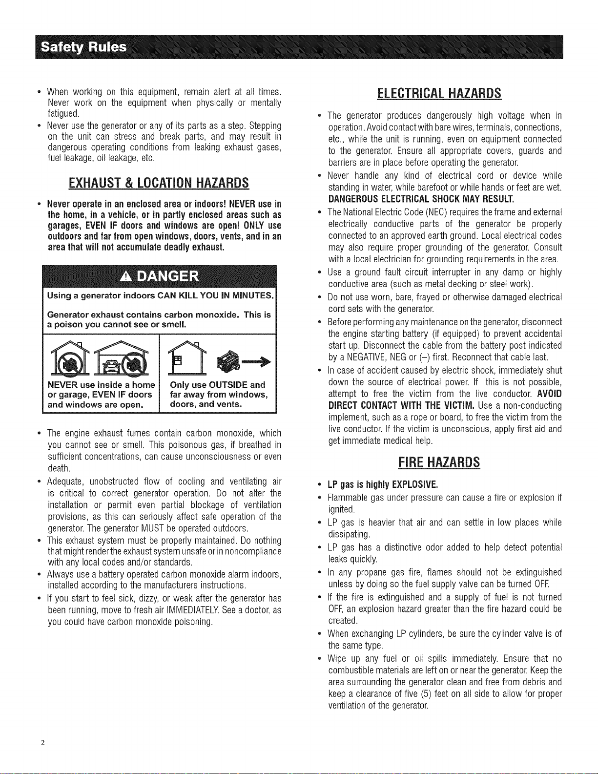
• Neveroperate in an enclosed areaor indoors!NEVERusein
the home,in a vehicle,or in partly enclosed areas suchas
garages,EVENIF doorsand windowsare open! ONLYuse
outdoors and far from openwindows, doors,vents,andinan
areathatwill notaccumulatedeadlyexhaust.
Using a generator indoors CAN KILL YOU IN MINUTES.
Generator exhaust contains carbon monoxide. This is
a poison you cannot see or smell,
NEVER use insidea home
or garage, EVEN iFdoors
and windows are open,
• The engine exhaustfumes contain carbon monoxide, which
you cannotsee or smell. This poisonous gas, if breathedin
sufficientconcentrations,can causeunconsciousnessor even
death.
• Adequate, unobstructed flow of cooling and ventilating air
is critical to correct generator operation. Do not alter the
installation or permit even partial blockage of ventilation
provisions, as this can seriously affect safe operationof the
generator.ThegeneratorMUSTbeoperatedoutdoors.
• Thisexhaustsystemmust beproperlymaintained.Do nothing
that mightrendertheexhaustsystemunsafeorinnoncompliance
with any localcodes and/or standards.
• Alwaysuse a batteryoperatedcarbonmonoxidealarmindoors,
installedaccordingto themanufacturersinstructions.
• If you start to feet sick, dizzy,or weak afterthe generatorhas
beenrunning,moveto fresh air IMMEDIATELYSeea doctor,as
you couldhave carbonmonoxidepoisoning.
Only use OUTSIDE and
far away from windows,
doors, and vents.
ELECTRICALHAZARDS
• The generator produces dangerously high voltage when in
operation.Avoidcontactwith barewires,terminals,connections,
etc., while the unit is running,even on equipmentconnected
to the generator. Ensureall appropriate covers, guards and
barriersarein place beforeoperatingthe generator.
• Never handle any kind of electrical cord or device while
standinginwater,while barefootorwhile handsor feet arewet.
DANGEROUSELECTRICALSHOCKMAYRESULT,
• TheNationalElectricCode(NEC)requirestheframe andexternal
electrically conductive parts of the generator be properly
connectedto an approvedearthground.Local electricalcodes
may also require proper groundingof the generator.Consult
with a local electricianfor groundingrequirementsin thearea.
• Use a ground fault circuit interrupter in any damp or highly
conductivearea(such as metaldecking orsteelwork).
• Do not useworn, bare,frayed or otherwisedamagedelectrical
cord setswith the generator.
• Beforeperforminganymaintenanceonthegenerator,disconnect
the enginestarting battery (if equipped)to preventaccidental
start up. Disconnectthe cablefrom the batterypost indicated
by aNEGATIVE,NEGor (-) first. Reconnectthatcable last.
• In caseof accidentcausedby electricshock, immediatelyshut
down the source of electrical power. If this is not possible,
attempt to free the victim from the live conductor. AVOID
DIRECTCONTACTWITHTHEVICTIIVl.Usea non-conducting
implement,such asa ropeorboard,to freethe victim fromthe
live conductor.If the victim is unconscious, apply first aid and
getimmediatemedical help.
FIREHAZARDS
• LPgas ishighlyEXPLOSIVE.
• Flammablegas underpressurecan causea fire or explosionif
ignited.
• LP gas is heavierthat air and can settle in low places while
dissipating.
• LP gas has a distinctive odor added to help detect potential
leaksquickly.
• In any propane gas fire, flames should not be extinguished
unlessby doing so thefuel supplyvalve can be turnedOFE
• If the fire is extinguishedand a supply of fuel is not turned
OFF,an explosion hazardgreaterthanthe fire hazardcould be
created.
• WhenexchangingLPcylinders, be surethe cylindervalveis of
thesametype.
• Wipe up any fuel or oil spills immediately.Ensure that no
combustiblematerialsareleft on ornearthegenerator.Keepthe
areasurroundingthe generatorcleanandfree from debrisand
keepa clearanceof five (5)feet on allside to allow for proper
ventilationof the generator.
Page 5

* Do notinsert objectsthrough unit's cooling slots.
* Do not operatethe generator if connected electrical devices
overheat,if electricaloutputis lost, if engineorgeneratorsparks
or ifflames orsmokeare observedwhileunit is running.
* Keepafire extinguishernearthe generatoratall times.
STANDARDS/NDEZ
1. NationalFireProtectionAssociation(NFPA)70:TheNATIONAL
ELECTRICCODE(NEC)availablefrom www.nfpa.org
2. NationalFire ProtectionAssociation (NFPA)5000: BUILDING
CONSTRUCTIONAND SAFETYCODEavailablefrom www.
nfpa.org
3. InternationalBuildingCodeavailablefrom www.iccsafe.org
4. Agricultural Wiring Handbookavailablefrom www.rerc.org ,
Rural ElectricityResourceCouncil RO.Box 309 Wilmington,
OH45177-0309
5. ASAEEP-364.2Installationand Maintenanceof FarmStandby
Electric Power available from www.asabe.org, American
Society of Agricultural & Biological Engineers2950 Niles
Road,St. Joseph,MI 49085
This list is not all inclusive.Checkwith the Authority HavingLocal
Jurisdiction (AHJ)for any local codes or standardswhich may be
applicableto yourjurisdiction.
MODELNO:
SERIALNO:
Unit ID Location
CALIFORNIAPROPOSITION65 WARNING
Engineexhaustandsomeof its constituentsareknown
to theStateof Californiato causecancer,birth defects
andotherreproductiveharm.
CALIFORNIAPROPOSITION65 WARNING
This productcontainsoremitschemicalsknown tothe
Stateof Californiato causecancer,birth defectsand
otherreproductiveharm.
Page 6
1.1 UNPACKING
* Removeall packagingmaterial.
* Removethe generatorfrom carton.
* Removeseparateaccessorybox.
NOTE:
Standard 20poundLPcylinder(tank)isnot included.
I.I.1 ACCESSORYBOX
Checkall contents.If anyparts aremissing or damaged,locatean
authorizeddealerat 1-888-436-3722.
* 1 - Owner'sManual * 1 -TankBracket
* 0.6 - Liter OilSAE10W-30 * 1 - FrameFoot
* 2 - Never-FlatWheels • 1 - TankShroud
* 1 - OilFunnel
* 1 - HardwareBag(containingthefollowing):
- 2-RubberFeet - 6-M8Bolt(Long)
- 2-1/2"AxlePins - 2-M8Bolts(Short)
- 2-CotterPins - 6-HexFlangedM8Nuts
- 2-1/2"FlatWashers
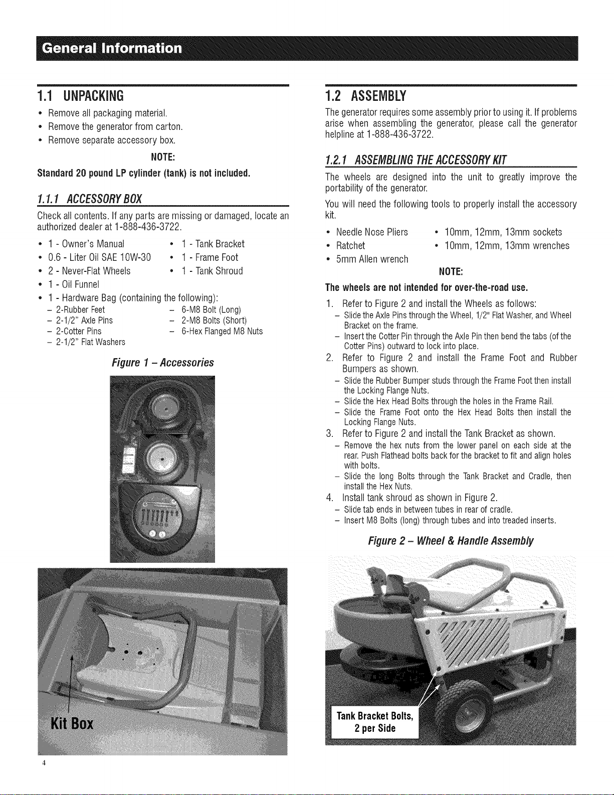
Figure 1 - Accessories
1.2 ASSEMBLY
Thegeneratorrequiressomeassemblypriorto usingit.If problems
arise when assemblingthe generator,please call the generator
hetplineat 1-888-436-3722.
1.2.1 ASSEMBLINGTHEACCESSORYKIT
The wheels are designed into the unit to greatly improve the
portability ofthe generator.
Youwilt needthe following tools to properly installthe accessory
kit.
* NeedleNosePliers * lOmm, 12mm, 13mmsockets
* Ratchet * lOmm, 12mm, 13mmwrenches
* 5mmAllenwrench
NOTE:
Thewheels are not intendedfor over-the-road use.
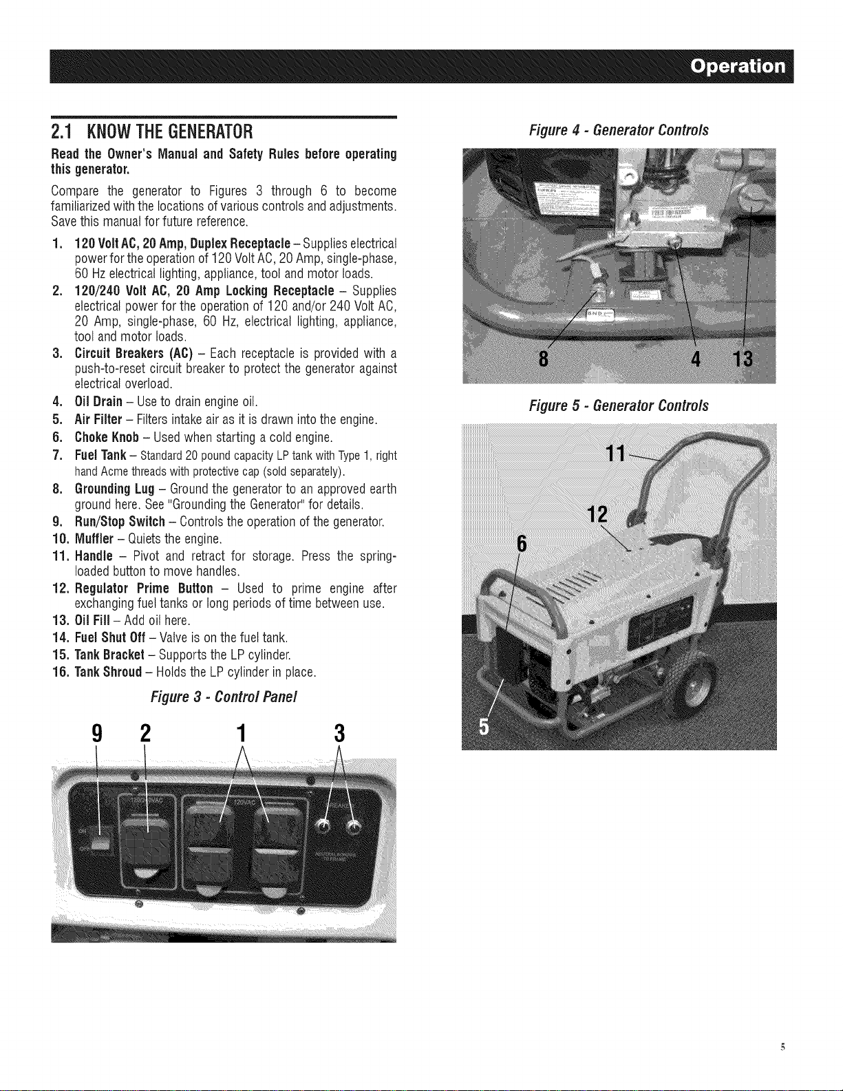
1. Refer to Figure 2 and install the Wheels as follows:
- Slidethe AxlePinsthroughthe Wheel,1/2" FlatWasher,andWheel
Bracketon theframe.
- Insertthe CotterPinthroughthe AxlePinthen bendthetabs (ofthe
CotterPins) outwardto lock into place.
2. Refer to Figure 2 and install the Frame Foot and Rubber
Bumpers as shown.
- Slidethe RubberBumperstuds throughthe FrameFootthen install
the LockingFlangeNuts.
- Slidethe HexHeadBoltsthrough theholes in the FrameRail.
- Slide the Frame Foot onto the Hex Head Bolts then install the
LockingFlangeNuts.
3. Refer to Figure 2 and install the Tank Bracket as shown.
- Removethe hex nuts from the lower panelon each side at the
rear.Push Flatheadbolts back forthe bracketto fit and alignholes
with bolts.
- Slide the long Bolts through the Tank Bracketand Cradle,then
installthe HexNuts.
4. Install tank shroud as shown in Figure 2.
- Slidetab ends in betweentubes in rear of cradle.
- Insert M8 Bolts (long) throughtubes andintotreaded inserts.
Figure 2 - Wheel & Handle Assembly
Page 7
2.1 KNOWTHEGENERATOR
Read the Owner'sIVlanualand Safety Rules before operating
thisgenerator.
Compare the generator to Figures 3 through 6 to become
familiarizedwith thelocationsof variouscontrolsandadjustments.
Savethis manualfor futurereference.
1. 120 VoltAC,20 Amp,DuplexReceptacle- Supplieselectrical
powerfor theoperationof 120VoltAC, 20Amp,single-phase,
60 Hzelectrical lighting,appliance,tool andmotor loads.
2. 120/240 Volt AC, 20 Amp LockingReceptacle- Supplies
electricalpowerfor the operation of 120 and/or240 VoltAC,
20 Amp, single-phase,60 Hz, electrical lighting, appliance,
tool andmotor loads.
3. Circuit Breakers (AC)- Each receptacle is providedwith a
push-to-resetcircuit breakerto protectthe generatoragainst
electricaloverload.
4. Oil Drain- Useto drainengineoil.
5. Air Filter- Filters intakeair as it is drawn intothe engine.
6. ChokeKnob- Usedwhen startinga coldengine.
7. Fuel Tank- Standard20poundcapacityLPtankwithType1,right
handAcmethreadswithprotectivecap(soldseparately).
8. Grounding Lug- Groundthe generatorto anapprovedearth
groundhere.See"GroundingtheGenerator"for details.
9. Run/Stop Switch- Controlsthe operationof the generator.
10. IViuffler- Quietsthe engine.
11. Handle - Pivot and retract for storage. Press the spring-
loadedbuttonto move handles.
12. Regulator Prime Button - Used to prime engine after
exchangingfuel tanksor long periodsof time betweenuse.
13. Oil Fill-Add oil here.
14. FuelShut Off- Valve is on the fuel tank.
15. TankBracket- Supportsthe LPcylinder.
18. TankShroud- Holdsthe LP cylinderin place.
Figure4 - GeneratorControls
Figure 5 - GeneratorControls
Figure3 - Contro/Pane/
9 2 1 3
Page 8
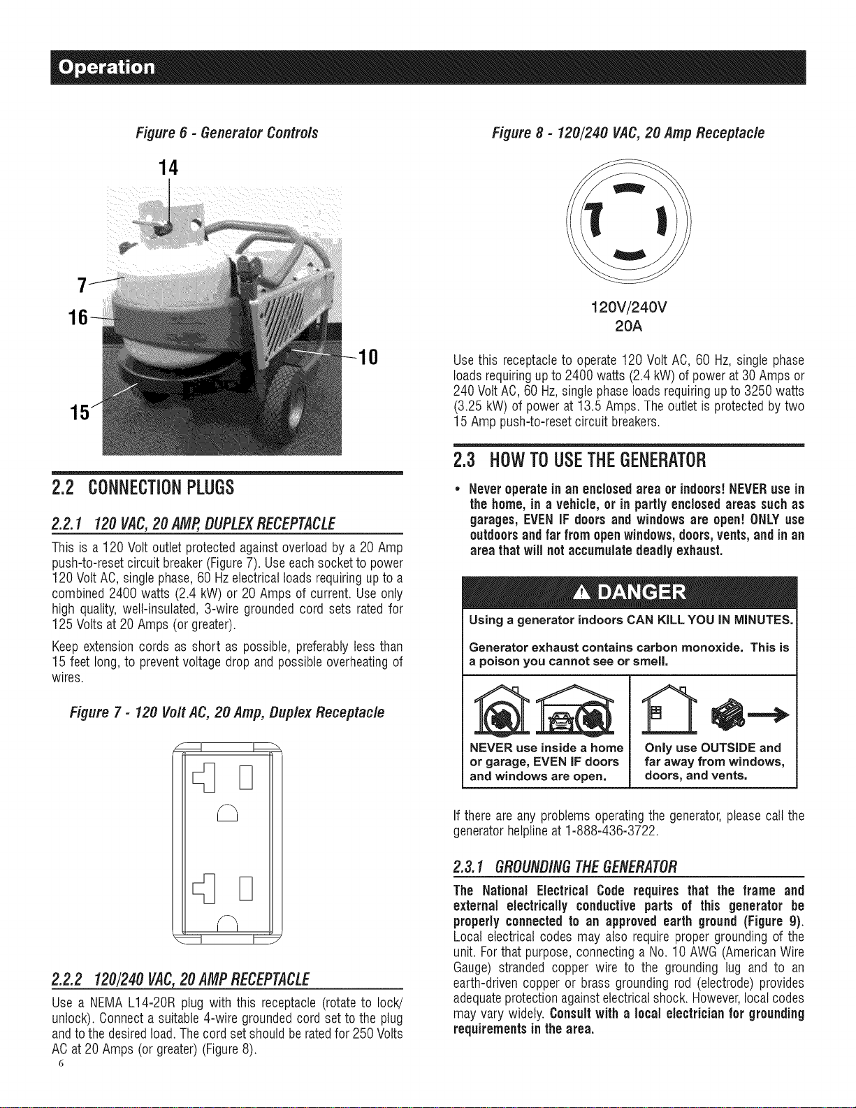
Figure 6 - Generator Contro/s
14
Figure 8 - 120/240 VAC,20 Amp Receptacle
120V/240V
20A
0
2.2 CONNECTIONPLUGS
2.2.1 120VAC,20 AMP,DUPLEXRECEPTACLE
This is a 120 Volt outletprotectedagainst overloadby a20 Amp
push-to-resetcircuitbreaker(Figure7). Useeachsocketto power
120 Volt AO,singlephase,60 Hzelectricalloadsrequiringupto a
combined 2400 watts (2.4 kW) or 20 Amps of current. Useonly
high quality,well-insulated, 3-wire grounded cord sets ratedfor
125 Volts at 20 Amps (or greater).
Keep extensioncords as short as possible, preferablyless than
15 feet long, to preventvoltage drop and possibleoverheatingof
wires.
Figure 7- 120 Volt AC, 20 Amp, Duplex Receptacle
Use this receptacleto operate120 Volt AC,60 Hz, singlephase
loadsrequiringup to 2400 watts (2.4kW) of power at 30 Ampsor
240 Volt AC,60 Hz,singlephase loadsrequiringup to 3250 watts
(3.25 kW)of power at 13.5 Amps.Theoutlet is protectedby two
15 Amp push-to-resetcircuit breakers.
2.3 HOW TO USETHEGENERATOR
Never operatein anenclosedareaor indoors!NEVERuse in
the home,in a vehicle, or in partly enclosed areas suchas
garages,EVENIF doorsand windows are open! ONLYuse
outdoors and far from openwindows,doors,vents,and inan
area that will not accumulate deadly exhaust.
Using a generator indoors CAN KILL YOU IN MINUTES.
Generator exhaust contains carbon monoxide. This is
a poison you cannot see or smell,
NEVER use insidea home
or garage, EVEN IF doors
and windows areopen.
Only use OUTSIDE and
far away from windows,
doors, and vents.
2.2.2 120/240VAC,20 AMPRECEPTACLE
Use a NEMA L14-20R plug with this receptacle(rotate to lock!
unlock). Oonnecta suitable4-wire groundedcord setto the plug
andto thedesiredtoad.Thecord set shouldbe ratedfor 250Volts
ACat20 Amps (or greater)(Figure8).
6
If thereare any problems operatingthe generator,pleasecall the
generatorhelplineat 1-888-436-3722.
2.3.1 GROUNDINGTHEGENERATOR
The National Electrical Code requires that the frame and
external electrically conductive parts of this generator be
properlyconnectedto an approved earth ground (Figure g).
Local electrical codes may also requireproper grounding of the
unit. Forthat purpose,connectinga No. 10 AWG(AmericanWire
Gauge) stranded copper wire to the grounding lug and to an
earth-driven copper or brass grounding rod (electrode)provides
adequateprotectionagainstelectricalshock. However,localcodes
may vary widely. Consultwith a localelectrician for grounding
requirementsin the area.
Page 9
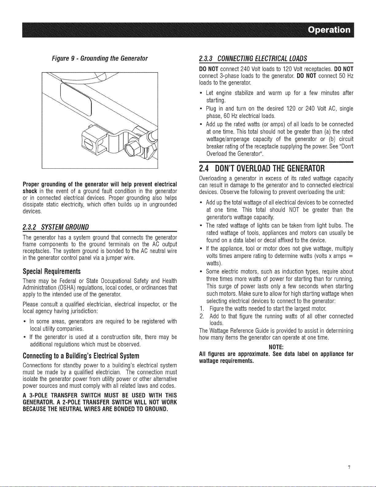
Figure g - Grounding the Generator
Propergroundingof the generatorwill help preventelectrical
shockin the event of a ground fault condition in the generator
or in connectedelectrical devices. Proper grounding also helps
dissipate static electricity,which often builds up in ungrounded
devices.
2.3.2 SYSTEMGROUND
Thegeneratorhas a system groundthat connectsthe generator
frame components to the ground terminals on the AC output
receptacles.The system groundis bondedto the AC neutralwire
in the generatorcontrol panelvia ajumperwire.
SpecialRequirements
There may be Federalor State OccupationalSafety and Health
Administration(OSHA)regulations,localcodes,or ordinancesthat
applyto the intendeduse ofthe generator.
Pleaseconsult a qualified electrician,electrical inspector, or the
local agencyhavingjurisdiction:
,, In some areas, generatorsare requiredto be registeredwith
local utilitycompanies.
* If the generatoris used at a construction site, there may be
additionalregulationswhich must be observed.
ConnectingtoaBuiiding'sElectricalSystem
Oonnectionsfor standby power to a building's electricalsystem
must be made by a qualified electrician. The connection must
isolatethe generatorpower from utility poweror otheralternative
powersourcesandmust complywith all relatedlaws andcodes.
A 3-POLETRANSFERSWITCH MUST BE USED WiTH THiS
GENERATOR.A 2-POLETRANSFERSWITCHWILL NOTWORK
BECAUSETHENEUTRALWIRESAREBONDEDTOGROUND.
2.3.3 CONNECTINGELECTRICALLOADS
DONOTconnect240 Volt loadsto 120 Volt receptacles.DONOT
connect 3-phaseloads to the generator.DO NOTconnect 50 Hz
loadsto the generator.
• Let engine stabilize and warm up for a few minutes after
starting.
• Plug in and turn on the desired 120 or 240 Volt AO, single
phase,60 Hzelectricalloads.
• Addup the ratedwatts (or amps) of all loadsto beconnected
at onetime. Thistotal should not begreaterthan (a) therated
wattage/amperagecapacity of the generator or (b) circuit
breakerratingof thereceptaclesupplyingthe power.See"Don't
OverloadtheGenerator".
2.4 DON'TOVERLOADTHEGENERATOR
Overloadinga generator in excess of its rated wattage capacity
can resultin damageto the generatorandto connectedelectrical
devices.Observethefollowing to preventoverloadingthe unit:
• Addupthetotal wattageofall electricaldevicesto be connected
at one time. This total should NOT be greater than the
generator'swattagecapacity.
• The ratedwattageof lights can betaken from light bulbs.The
ratedwattageof tools, appliancesand motors can usually be
foundon a data labelor decalaffixedto the device.
• If the appliance,tool or motor does not give wattage,multiply
voltstimes ampererating to determinewatts (voltsx amps =
watts).
• Some electric motors, such as inductiontypes, require about
threetimes morewatts of powerfor startingthan for running.
This surge of power lasts only a few seconds when starting
suchmotors. Makesureto allowfor high startingwattagewhen
selectingelectrical devicesto connectto the generator:
1. Figurethe watts neededto start the largestmotor.
2. Add to that figure the running watts of all other connected
loads.
TheWattageReferenceGuideis providedto assist in determining
how manyitemsthegeneratorcan operateat onetime.
NOTE:
All figures are approximate. See data label on appliance for
wattage requirements.
Page 10
2.5 WATTAGEREFERENCEGUIDE
Device................................... RunningWatts
*Air Conditioner(12,000 Btu).......................... 1700
*Air Conditioner(24,000 Btu).......................... 3800
*Air Conditioner(40,000 Btu).......................... 6000
BatteryCharger(20 Amp).............................. 500
BeltSander (3") .................................... 1000
ChainSaw ........................................ 1200
CircularSaw(6-1/2") ........................... 800 to 1000
*Clothes Dryer(Electric) ............................. 5750
*Clothes Dryer(Gas) ................................. 700
*Clothes Washer ................................... 1150
CoffeeMaker ...................................... 1750
*Compressor (1 HP)................................. 2000
*Compressor (3/4 HP)............................... 1800
*Compressor (1/2 HP)............................... 1400
CurlingIron......................................... 700
*Dehumidifier....................................... 650
Disc Sander(9").................................... 1200
EdgeTrimmer....................................... 500
Electric Blanket...................................... 400
Electric NailGun.................................... 1200
Electric Range(per element)........................... 1500
Electric Skillet...................................... 1250
*Freezer............................................ 700
*FurnaceFan(3/5 HP) ................................ 875
*GarageDoor Opener............................ 500 to 750
HairDryer......................................... 1200
Hand Drill.................................... 250 to 1100
HedgeTrimmer...................................... 450
Impact Wrench...................................... 500
Iron.............................................. 1200
*Jet Pump ......................................... 800
Lawn Mower....................................... 1200
Light Bulb.......................................... 1O0
Microwave Oven............................... 700 to 1000
*Milk Cooler....................................... 1100
OilBurneron Furnace................................. 300
OilFiredSpace Heater(140,000 Btu) ..................... 400
OilFiredSpace Heater(85,000 Btu) ...................... 225
OilFiredSpace Heater(30,000 Btu) ...................... 150
*Paint Sprayer,Airless(1/3 HP)......................... 600
PaintSprayer,Airless (handheld)......................... 150
Radio......................................... 50 to 200
*Refrigerator........................................ 700
SlowCooker........................................ 200
*SubmersiblePump (1-1/2 HP) ........................ 2800
*SubmersiblePump (1 HP) ........................... 2000
*SubmersiblePump (1/2 HP).......................... 1500
*Sump Pump................................. 800 to 1050
*Table Saw (10") ............................. 1750 to 2000
Television..................................... 200to 500
Toaster..................................... 1000 to 1650
WeedTrimmer ...................................... 500
* Allow 3 times the listedwatts for startingthese devices.
2.6 BEFORESTARTINGTHEGENERATOR
Priorto operatingthe generator,engineoil and LPfuelwill needto
be added,asfollows:
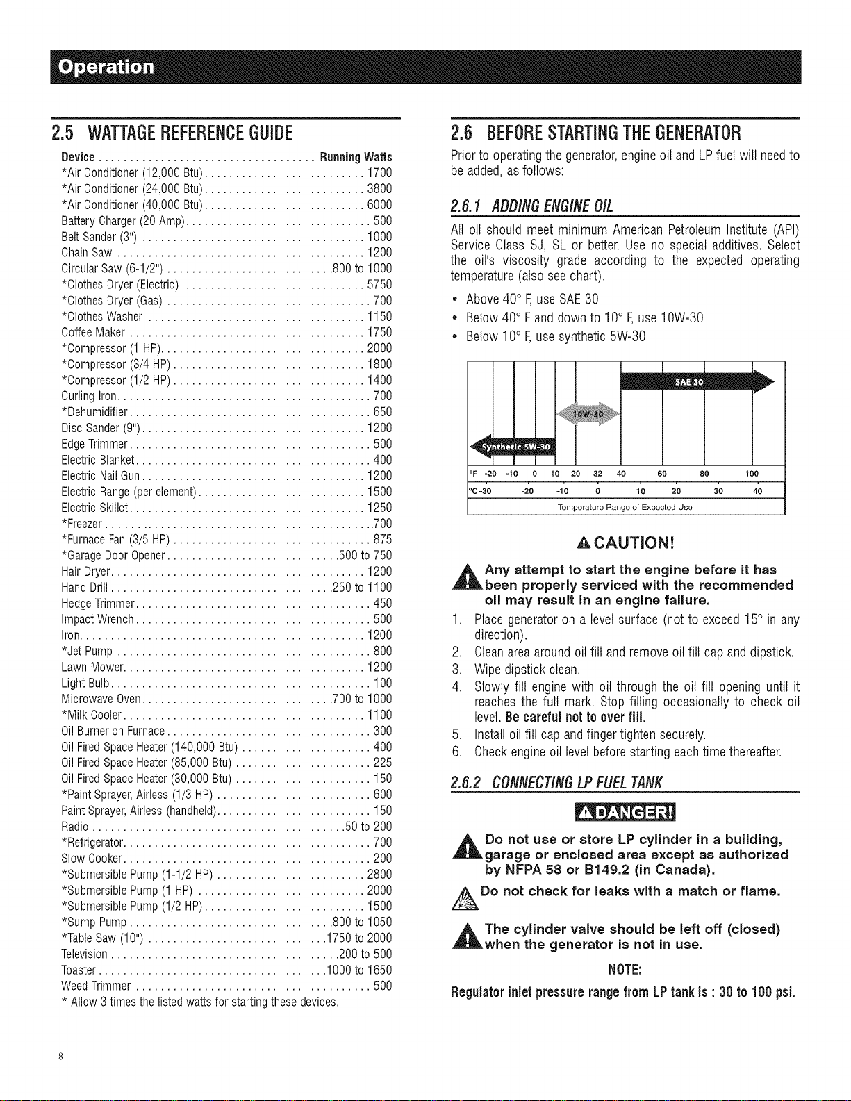
2.6.1 AOO/NGENGINEOIL
All oil should meet minimum American PetroleumInstitute (API)
Service Class SJ, SL or better. Use no special additives. Select
the oil's viscosity grade according to the expected operating
temperature(also see chart).
• Above40° F,useSAE30
• Below40° Fand down to 10° F,use10W-30
• Below10° F,use synthetic5W-30
°F =20 =10 0 10 20 32 40 60
'c4'o -2'0 -lo 0 lo 2o
Temperature Range of Expected Use
,&CAUTION!
_t ny attempt to start the engine before it has
been properly serviced with the recommended
oil may result in an engine failure.
1. Place generatoron a levelsurface (notto exceed15° in any
direction).
2. Cleanareaaroundoil fill andremoveoil fill cap anddipstick.
3. Wipe dipstick clean.
4. Slowly fill engine with oil through the oil fill opening until it
reachesthe full mark. Stop filling occasionally to check oil
level.Be carefulnotto overfill.
5. Install oil fill cap andfinger tighten securely.
6. Checkengineoil levelbefore starting eachtime thereafter.
2.6.2 CONNECTINGLPFUELTANK
Do not use or store LP cylinder in a building,
garage or enclosed area except as authorized
by NFPA 58 or B149.2 (in Canada).
Do not check for leaks with a match or flame.
,_The cylinder valve should be left off (closed)
when the generator is not in use.
NOTE:
Regulator inlet pressurerangefrom LPtankis : 30to 100 psi.
80 100
Page 11
• Use only standard 20 or 30 pound capacity LP tanks with
Type1, righthandAcmethreadswith this generator.Verifythe
requalificationdate on the tank has not expired. Do not use
rusted or damagedcylinders.
• All new cylinders must be purgedof air andmoisture prior to
filling. Usedcylindersthat havenotbeenpluggedor keptclosed
must alsobe purged.
• The purging process should be done by your propane gas
supplier. (Cylindersfrom an exchangesupplier should have
beenpurgedandfilled properlyalready)
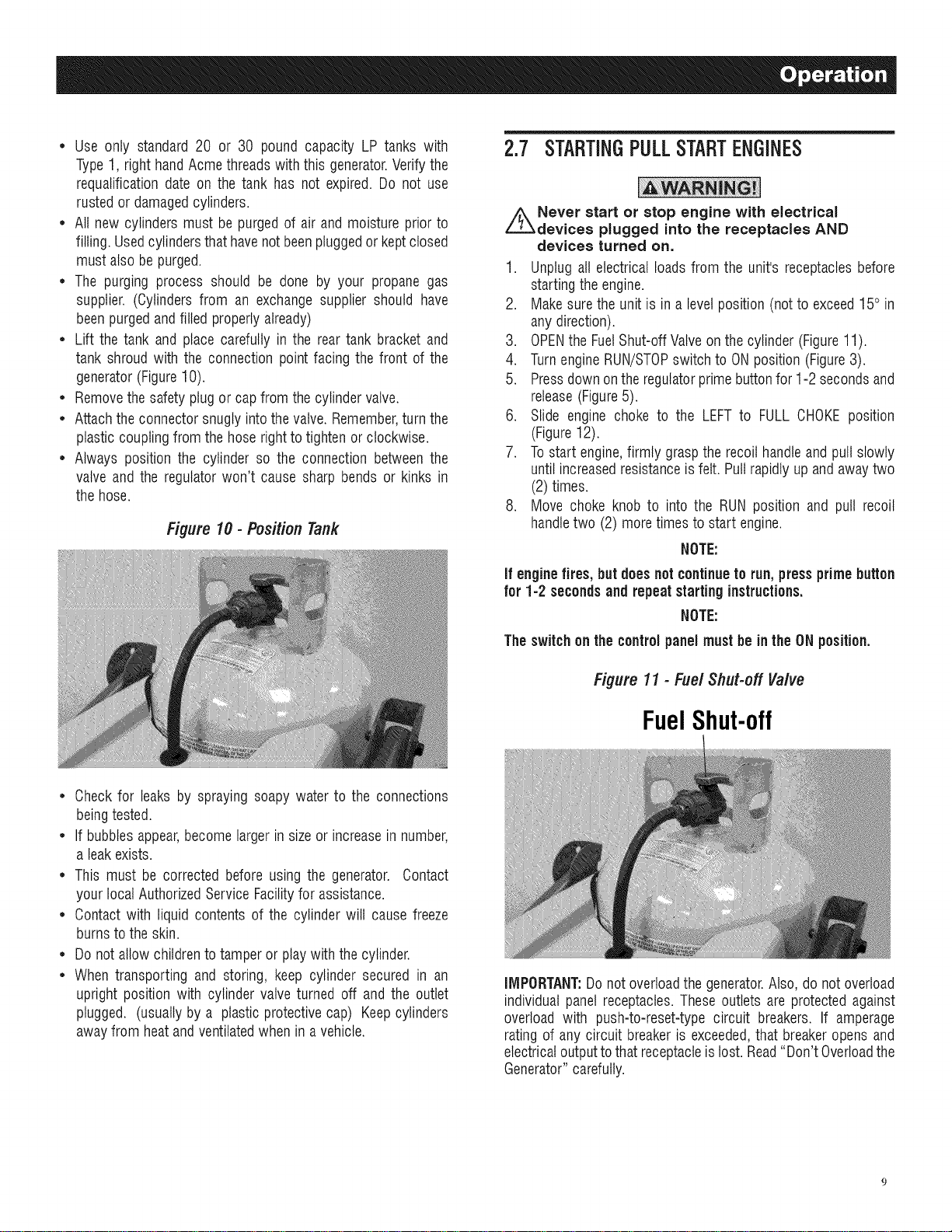
• Lift the tank and place carefully in the rear tank bracket and
tank shroudwith the connection pointfacing the front of the
generator(Figure10).
• Removethe safetyplugor capfrom thecylinder valve.
• Attachthe connectorsnuglyintothevalve.Remember,turn the
plasticcouplingfromthe hose rightto tightenor clockwise.
• Always position the cylinder so the connection betweenthe
valve and the regulatorwon't causesharp bends or kinks in
the hose.
Figure 10 - Position Tank
2.7 STARTINGPULLSTARTENGINES
//_Never start or stop engine with electrical
devices plugged into the receptacles AND
devices turned on.
1. Unplug all electricalloads from the unit's receptaclesbefore
startingthe engine.
2. Makesurethe unit is in a levelposition (notto exceed15° in
anydirection).
3. OPENthe FuelShut-offValveon thecylinder (Figure11).
4. TurnengineRUN/STOPswitch to ONposition (Figure3).
5. Pressdownonthe regulatorprimebuttonfor 1-2 secondsand
release(Figure5).
6. Slide engine choke to the LEFT to FULL CHOKEposition
(Figure12).
7. To start engine,firmly graspthe recoilhandleandpull slowly
until increasedresistanceis felt. Pullrapidly up andawaytwo
(2) times.
8. Move choke knob to into the RUN position and pull recoil
handletwo (2) moretimes to start engine.
NOTE:
If enginefires, but doesnot continueto run, pressprimebutton
for 1-2 secondsand repeatstarting instructions.
NOTE:
Theswitch on the controlpanelmust be inthe ONposition.
• Checkfor leaks by spraying soapy waterto the connections
beingtested.
• If bubblesappear,becomelargerin size or increasein number,
a leak exists.
• This must be corrected before using the generator. Contact
your localAuthorizedServiceFacilityfor assistance.
• Contactwith liquid contents of the cylinder will cause freeze
burnsto the skin.
• Do notallow childrento tamper or playwith thecylinder.
• When transporting and storing, keep cylinder secured in an
upright position with cylinder valve turned off and the outlet
plugged. (usuallyby a plastic protectivecap) Keepcylinders
awayfrom heat andventilatedwhen in a vehicle.
Figure 11 - Fuel Shut-off Valve
FuelShut-off
IMPORTANT:Donotoverloadthe generator.Also, do not overload
individual panelreceptacles.These outlets are protectedagainst
overload with push-to-reset-typecircuit breakers. If amperage
rating of any circuit breakeris exceeded,that breakeropens and
electricaloutputtothatreceptacleis lost.Read"Don't Overloadthe
Generator"carefully.
Page 12
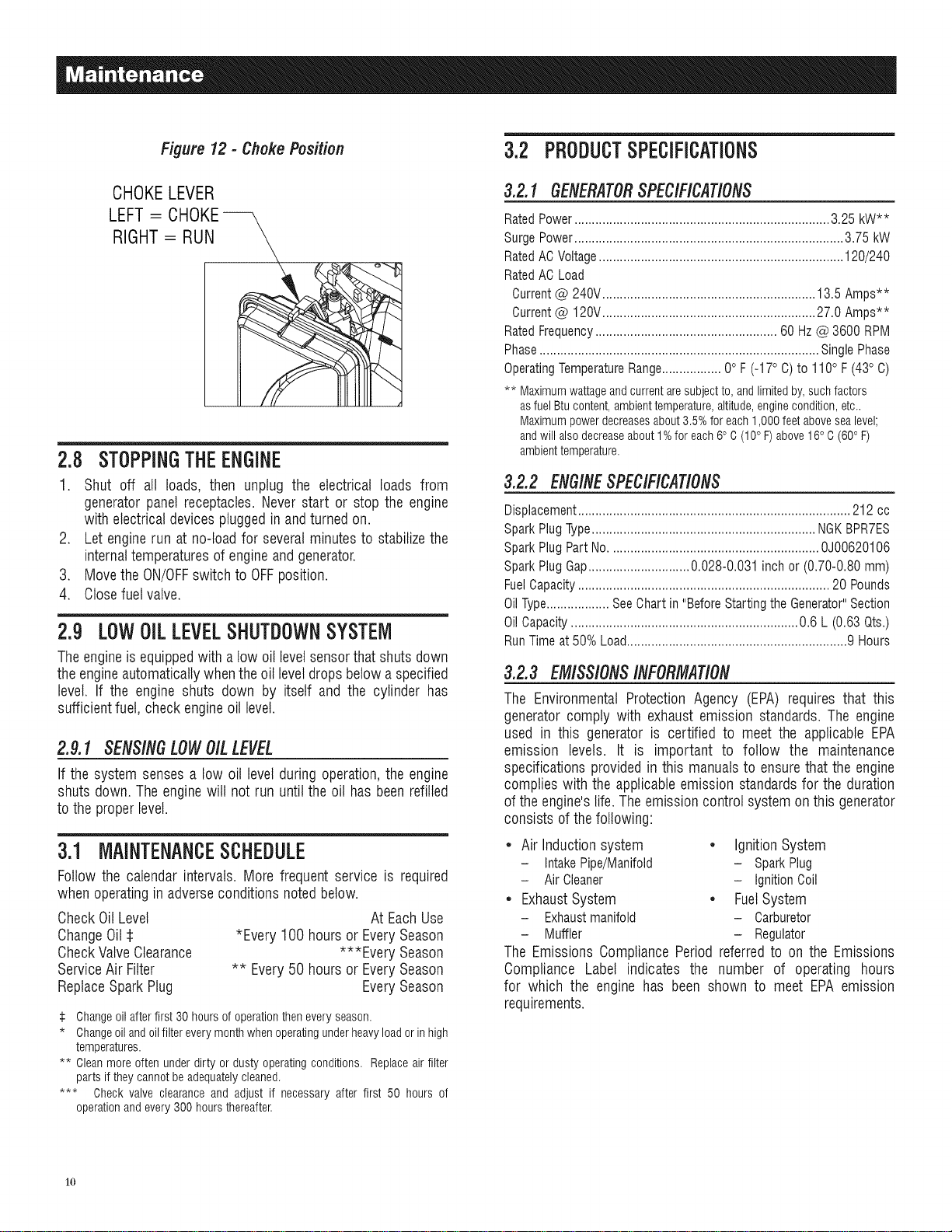
Figure 12 - Choke Position
3.2 PRODUCTSPECIFiCATiONS
CHOKELEVER
LEFT= CHOKE--
RIGHT= RUN
2.8 STOPPINGTHEENGINE
1. Shut off all loads, then unplug the
generatorpanel receptacles.Never start or stop the engine
with electrical devicespluggedin andturnedon.
2. Let enginerun at no-loadfor severalminutesto stabilizethe
internaltemperaturesof engineand generator.
3. Movethe ON/OFFswitch to OFFposition.
4. Closefuelvalve.
electrical loads from
2.9 LOWOiLLEVELSHUTDOWNSYSTEM
Theengineis equippedwitha low oil levelsensorthat shutsdown
the engineautomaticallywhenthe oil leveldropsbelowaspecified
level. If the engine shuts down by itself and the cylinder has
sufficientfuel, checkengineoil level.
2.9.1 SENSINGLOWOILLEVEL
If the system senses a low oil level during operation,the engine
shuts down.The enginewill not run untilthe oil has beenrefilled
to the properlevel.
3.1 MAINTENANCESCHEDULE
Follow the calendar intervals.More frequent service is required
whenoperatingin adverseconditions noted below.
CheckOil Level
ChangeOil
*Every 100 hoursor EverySeason
CheckValveClearance
ServiceAir Filter
** Every50 hoursor EverySeason
ReplaceSparkPlug
:i: Changeoil afterfirst 30 hours of operationthen every season.
* Changeoiland oilfilter every monthwhen operatingunder heavyload or inhigh
temperatures.
** Cleanmore often under dirty or dusty operating conditions. Replace air filter
parts ifthey cannot beadequatelycleaned.
*** Check valve clearance and adjust if necessary after first 50 hours of
operationand every300 hours thereafteK
At EachUse
***Every Season
EverySeason
3.2.1 GENERATORSPECIFICATIONS
RatedPower......................................................................... 3.25 kW**
SurgePower............................................................................. 3.75 kW
RatedACVoltage...................................................................... 120/240
RatedAC Load
Current@ 240V............................................................. 13.5 Amps**
Current@ 120V............................................................. 27.0 Amps**
RatedFrequency.................................................... 60 Hz@ 3600 RPM
Phase................................................................................ SinglePhase
OperatingTemperatureRange................. 0° F(-17° C) to 110° F(43° C)
** Maximumwattageandcurrentaresubjectto,andlimitedby,suchfactors
asfuelBtucontent,ambienttemperature,altitude,enginecondition,etc..
Maximumpowerdecreasesabout3.5%for each1,000feetabovesealevel;
andwillalsodecreaseabout1%for each6° C (10° F)above16° C(60° F)
ambienttemperature.
3.2.2 ENG/NESPECIFICATIONS
Displacement.............................................................................. 212 cc
SparkPlugType................................................................ NGKBPR7ES
SparkPlug PartNo............................................................ 0J00620106
SparkPlug Gap.............................0.028-0.031 inch or (0.70-0.80 mm)
FuelCapacity........................................................................ 20 Pounds
OilType.................. SeeChartin "BeforeStarting the Generator"Section
OilCapacity................................................................. 0.6 L (0.63 Qts.)
RunTime at 50% Load...............................................................9 Hours
3.2.3 EMISSIONSINFORMATION
The EnvironmentalProtection Agency (EPA) requires that this
generatorcomply with exhaust emission standards. The engine
used in this generator is certified to meet the applicable EPA
emission levels. It is important to follow the maintenance
specifications provided in this manualsto ensurethat the engine
complieswith the applicableemission standardsfor the duration
of theengine'slife. Theemissioncontrol system onthis generator
consists ofthe following:
• Air Induction system • Ignition System
- IntakePipe/Manifold - SparkPlug
- Air Cleaner - IgnitionCoil
• Exhaust System • Fuel System
- Exhaustmanifold - Carburetor
- Muffler - Regulator
The EmissionsCompliancePeriod referred to on the Emissions
Compliance Label indicates the number of operating hours
for which the engine has been shown to meet EPA emission
requirements.
1o
Page 13

3.3 GENERALRECOIVliViENDATiONS
Thewarranty of the generatordoesnotcover itemsthathave been
subjectedto operator abuse or negligence.To receive full value
from the warranty, the operatormust maintainthe generatoras
instructed inthis manual.
Some adjustmentswill needto be made periodicallyto properly
maintainthegenerator.
All adjustments in the Maintenancesection of this manualshould
bemadeat leastonceeachseason.Followthe requirementsin the
"MaintenanceSchedule".
NOTE:
Once a year replace the sparkplug and replacethe air filter.
A new spark plug and clean air filter assure proper fuel-air
mixtureandhelp the enginerun better andlast longer.
3.3.1GENERATOR/V/A/NTENANCE
Generatormaintenanceconsists of keepingtheunitcleanand dry.
Operateandstorethe unitin a clean dry environmentwhere it will
not beexposedto excessivedust, dirt, moistureor any corrosive
vapors. Cooling air slots in the generator must not become
cloggedwith snow, leaves,or anyother foreign material.
Checkthe cleanlinessof the generatorfrequently andcleanwhen
dust, dirt, oil, moisture or otherforeign substancesarevisible on
its exteriorsurface.
_,CAUTION!
,_ Never insert any object or tool through the air
cooling slots, even if the engine is not running.
NOTE:
DONOTuse agarden hoseto cleangenerator. Water canenter
the enginefuelsystemand causeproblems.In addition,if water
enters thegenerator throughcoolingair slots,some water will
be retained invoidsand crevicesof the rotorand statorwinding
insulation.Water and dirt buildup on the generator internal
windingswill eventually decrease the insulationresistanceof
thesewindings.
3.3.2 TOCLEANTHEGENERATOR
* Usea damp cloth to wipe exteriorsurfaces clean.
* A soft, bristlebrush may be used to loosencaked on dirt, oil,
etc.
* A vacuum cleaner may be used to pick up loose dirt and
debris.
* Low pressure air (not to exceed 25 psi) may be used to
blow away dirt. Inspect cooling air slots and openings
on the generator.These openings must be kept clean and
unobstructed.
3.3.3 ENGINEMAINTENANCE
When working on the generator, always
disconnect spark plug wire from spark plug and
keep wire away from spark plug.
3.3.4 CHECKINGOILLEVEL
Seethe "BeforeStartingthe Generator"sectionfor informationon
checkingthe oil level.Theoil levelshouldbe checkedbeforeeach
use, or at least everyeight hours of operation.Keepthe oil level
maintained.
3.3.5 CHANG/NGTHEO/L
Changethe oil after the first 30 hours and every 100 hours
thereafter.If runningthisunit underdirty or dusty conditions,or in
extremelyhot weather,changethe oil moreoften.
,A.CAUTION!
,_Hot oil may cause burns. Allow engine to
cool before draining oil. Avoid prolonged
or repeated skin exposure with used oil.
Thoroughly wash exposed areas with soap.
Use thefollowing instructionsto changetheoil afterthe engine
coolsdown:
1. Cleanareaaroundoil drainplug.
2. Removeoil drainplug from engineandoil fill plugto drainoil
completelyinto a suitablecontainer.
3. When oil has completely drained, install oil drain plug and
tightensecurely.
4. Fill enginewith recommendedoil. (See "Before Starting the
Generator"for oil recommendations).
5. Wipe up anyspilled oil.
6. Disposeof usedoil at a propercollectioncenter.
3.3.6 REPLACINGTHESPARKPLUG
UseNGKBPR7ESsparkplugor equivalent. Replacetheplug once
eachyear.
.
Stopthe engineand shut offthefuelvalve onthe cylinderand
remove.
2.
Using a 13mm wrench and 6mm Allen wrench, removethe
four (4)flat headscrews andtwo (2) hex nutsfrom the side
panel and 3 button head screws adjacentto the top cover.
Removethe exhaustside panelto gain access to the spark
plug (Figure13).
11
Page 14

Figure 13 - Remove Screws
TopCoverScrews
Nutsbehind
thesetwo
screws,
FlatHeadScrews
.
Removethe sparkplugwire off ofthe plugand cleanthat area
ofthe cylinderhead(Figure14).
Figure 14 - Remove Spark Plug Wire
SparkPlug
3.4 SERVICEAiRFILTER
Theenginewill not run properlyand may be damagedif using a
dirty air filter. Cleanthe air filter every50 hours or once a year
(Figure16). Cleanor replacemore often if operatingunder dusty
conditions.Theair filter part numberis 0J47870141.
1. Removeairfilter cover.
2. Washinsoapywater.Squeezefilter dry in cleancloth (DONOT
TWIST).
3. Cleanair filtercover before reqnstallingit.
NOTE:
Toorder a new air filter, pleasecontactthe nearestauthorized
service centerat 1-888-435-3722.
Figure 16 - Air Filter
4. Usea 21mm (13/16") sparkplug socketto removethe spark
plug.
5. Setthe newsparkplug'sgapto 0.70-0.80 mm (0.028- 0.031
in). Installthe correctly gapped spark plug into the cylinder
headandtighten enoughto ensurethe gasketcompressesat
(18.0to 21.6 Pound/Feet)(Figure15).
6. Reconnectthe spark plugwire and replacethe exhaustside
panelandseven (7)fasteners.
Figure 15 - Spark Plug Gap
12
3.5 VALVECLEARANCE
* Intake-- 0.15 _+O.02mm(cold), (0.006" _ 0.0008")
* Exhaust-- 0.20 _+O.02mm(cold) (0.008" _+0.0008")
Afterthe first 50 hoursof operation,checkthe valve clearance
in the engineand adjust if necessary.
important:Iffeeling uncomfortableabout doing this procedureor
theproper tools arenot available,pleasetakethe generatorto the
nearestservicecenterto havethevalveclearanceadjusted.Thisis
a very important stepto ensurelongestlife for theengine.
3.6 GENERAL
Thegeneratorshould be started at leastonceevery 30 days and
be allowed to run at least30 minutes. Ifthis cannot bedoneand
the unit must be storedfor more than 30 days, usethe following
informationas aguideto prepareitfor storage.
,_AIIow unit to cool entirely before storage.
Page 15

3.7 LONGTERMSTORAGE
1. Drain oil from crankcaseafter the engine cools down. Refill
with recommendedgrade.
2. Remove spark plug and pour about 1/2 ounce (15 mt) of
engineoil into thecylinder.Coverspark plugholewith rag.Putt
the recoil starter a couple times to lubricatethe piston rings
and cylinderbore.
_CAUTION!
_1 void spray from spark plug hole when
cranking engine.
3. Install andtightenspark plug.Donot connectsparkplugwire.
4. Clean the generator outer surfaces. Check that cooling air
slots andopeningsongeneratorareopen andunobstructed.
5. Storethe unit ina clean, dry place.
3.8 OTHERSTORAGETiPS
* If possible,storethe unit indoorsandcover it to giveprotection
from dust and dirt. BESURETO CLOSETHE VALVEON THE
FUELTANK.
* Coverthe unit with a suitable protectivecover that does not
retainmoisture.
_t NEVER cover the generator while engine and
exhaust areas are warm,
13
Page 16

4.1 TBOUBLESHOOTINGGUIDE
Engine is running,but no ACoutput 1. Circuit breakeris open. 1. Resetcircuit breaker.
is available. 2. Poorconnection or defectivecord set. 2. Check and repair.
3. Connecteddevice is bad. 3. Connect anotherdevicethat is in good condition.
4. Faultingenerator. 4. ContactAuthorizedServiceFacility.
i
Engine runswell hut bogsdown 1. Short circuit in a connected load. 1. Disconnect shorted electricalload.
whenloads areconnected. 2. Generatoris overloaded. 2. See"Don't Overloadthe Generator".
3. Enginespeedis tooslow. 3. ContactAuthorizedService Facility.
4. Shorted generatorcircuit. 4. ContactAuthorizedServiceFacility.
Enginewill not start; or starts and 1. FuelShut-offis OFF. 1. Turn FuelShut-off ON.
runsrough. 2. Dirty air filter. 2. Cleanor replaceair filter.
3. Out offuel. 3. Replacethe fuel tank.
5. Sparkplug wire not connectedto spark plug. 5. Connect wireto spark plug.
6. Badspark plug.
7. Water in fuel or cylinder overfilled.
8. Overchoking.
9. Low oil level.
10. Excessiverich fuelmixture.
11. Intakevalve stuck open or closed.
12. Enginehas lost compression.
6. Replacespark plug.
7. Replacecylinder.
8. Put chokeknobto No Chokeposition.
9. Fill crankcaseto properlevel.
10. ContactAuthorizedServiceFacility.
11. ContactAuthorizedServiceFacility.
12. ContactAuthorizedServiceFacility.
Engineshuts downduring 1. Out offuel. 1. Replacethe fuel tank.
operation. 2. Lowoil level. 2. Fill crankcaseto properlevel.
3. Faultinengine. 3. Contact AuthorizedService Facility.
Engine lacks power. 1. Loadis toohigh. 1. Reduceload (see"Don't Overloadthe Generator").
2. Dirtyair filter. 2. Cleanor replaceair filter.
3. Engineneedsto be serviced. 3. Contact AuthorizedServiceFacility.
Engine "hunts" orfalters. 1. Chokeis openedtoo soon. 1. Movechoketo halfwayposition untilengineruns
smoothly.
2. Carburetoris runningtoo rich or too lean. 2. ContactAuthorizedServiceFacility.
14
Page 17

15
Page 18

U,S, EPA EMiSSiON CONTROL WARRANTY STATEMENT
YOUR WARRANTY RIGHTS AND OBLiGATiONS
TheUnited StatesEnvironmentalProtectionAgency (EPA)and GeneracPower Systems,Inc. (Generac)are pleasedto explainthe Emission Control
SystemWarranty (ECSWarranty) on yournew 2011 and later equipment.New equipmentthat use small spark-ignitedenginesmust bedesigned,built,
andequipped to meetstringentanti-smog standardsfor the federalgovernment.Generacwill warrantthe emission control system on your equipment
for the period of time listed belowprovidedthere has beenno abuse, neglect,unapprovedmodificationor improper maintenanceof your equipment.
Theemission control system onthis equipmentincludes all componentswhose failurewould increasethe emissionsof anyregulatedpollutant. These
componentsare listed inthe Emissions Information sectionof this manual.
MANUFACTURER'S WARRANTY COVERAGE:
This ECSWarranty is validfor two years,or for the sameperiod as specifiedin the GeneracLimited Warranty,whicheveris longer.Forequipmentwith
hourmeters,the warranty periodis anumber of hours equalto halfthe UsefulLifeto which the equipmentis certified, or the warranty period specified
abovein years,whicheveris less. The UsefulLife can befound onthe EmissionControl Labelon theengine.If, during suchwarranty period,any
emission-relatedpart on your equipment isfound to be defectivein materials or workmanship,repairs or replacementwill be performed by aGenerac
AuthorizedWarrantyService Dealer.
OWNER'S WARRANTY RESPONSiBiLiTiES:
Asthe equipmentowner,you areresponsiblefor the completion of all requiredmaintenanceas listed inyour factory suppliedOwner'sManual.For
warranty purposes,Generacrecommendsthat you retainall receiptscovering maintenanceon your generator,butGeneraccannotdeny warranty
solelydueto the lack of receipts.
Youshould beawarethat Generacmay denyanyand/or all warrantycoverageor responsibilityif your equipment,or apart!componentthereof,has
failed due to abuse,neglect, impropermaintenance,or unapprovedmodifications.
Youare responsible for contactingaGeneracAuthorizedWarrantyDealeras soonas a problemoccurs.Thewarranty repairsshouldbe
completed in a reasonable amount oftime, not to exceed 30 days.
Warrantyservicecan bearrangedby contactingeitheryour sellingdealeror a GeneracAuthorizedWarrantyServiceDealer.Tolocate the Generac
AuthorizedWarrantyService Dealernearestyou, call ourtoll free numberbelow, oremail emissions@generac.com.
1-800-333-1322
IMPORTANTNOTE:Thiswarranty statementexplainsyour rights and obligationsunder the Emission Control SystemWarranty,which is providedto
you by Generacpursuantto federallaw. Seealso the "GeneracLimitedWarrantiesfor GeneracPowerSystems,Inc.," which is enclosedherewith on a
separatesheet,also providedto you byGenerac.Notethat this warranty shallnot apply to any incidental,consequentialor indirect damagescaused
bydefects in materialsor workmanshipor any delayin repairor replacementof thedefectivepart(s). This warranty is inplace of all otherwarranties,
expressedor implied. Specifically,Generacmakesno other warrantiesas to the merchantabilityor fitness for a particular purpose.Any implied
warrantieswhich areallowed by law,shall be limitedin durationto theterms of the expresswarranty providedherein.Somestatesdo notallow
limitationson how long an impliedwarranty lasts, sothe abovelimitation maynot applyto you.
TheECSWarranty appliesonly to the emissioncontrol system of your newequipment. Boththe ECSWarrantyandthe GeneracWarrantydescribe
importantrights andobligationswith respectto your new engine.
Warrantyservicecan beperformed onlyby a GeneracAuthorizedWarrantyService Facility.When requestingwarranty service,evidencemust be
presentedshowingthe date ofthe saleto the originalpurchaser/owner.
Ifyou have anyquestionsregardingyour warranty rights and responsibilities,you should contact Generacatthe following address:
ATTENTION WARRANTY DEPARTMENT
GENERAC POWER SYSTEMS, INC.
P.O. BOX 297 • WHITEWATER, Wi 53190
PartI of 2
PartNo. 0J3335 Rev.C 11/11
16
Page 19

EMiSSiON CONTROL SYSTEM WARRANTY
EmissionControlSystem Warranty (ECSWarranty)for equipmentusing small spark-ignitedengines:
(a) Applicability: This warrantyshall applyto equipmentthat usessmall off-road engines.TheECSWarranty periodshall begin on the datethe new
equipmentis purchasedby/deliveredto its original, end-usepurchaser/ownerand shall continue for the lesserof:
(1) The periodof time specifiedin the GeneracLimitedWarrantyenclosedherewith,but not less than24 months, or
(2) Forenginesequippedwith hour meters,a numberof operatinghours equalto half ofthe engine'susefullife.The usefullife is specifiedon the
EmissionsControl Labelon theengine.
(b) GeneralEmissionsWarrantyCoverage:Generacwarrantsto the original,end-usepurchaser/ownerof the newengineor equipmentandto each
subsequentpurchaser/ownerthat the ECSwhen installed was:
(1) Designed,built and equippedso asto conform with all applicableregulations;and
(2) Freefrom defectsin materialsand workmanship which causethe failureof a warranted part at anytime duringthe ECSWarranty Period.
(c) Thewarranty on emissions-relatedparts will be interpretedasfollows:
(1) Any warrantedpart thatis not scheduledfor replacementas requiredmaintenancein theOwner'sManualshall bewarrantedfor the ECS
WarrantyPeriod.If any such partfails duringthe ECSWarrantyPeriod, it shallbe repairedor replaced by Generacaccordingto Subsection
(4) below.Any such part repairedor replacedunderthe EOSWarranty shall bewarrantedforthe remainderof theECSWarranty Period.
(2) Any warrantedpart thatis scheduledonlyfor regularinspection asspecified in the Owner'sManualshallbe warrantedfor the EOSWarranty
Period.A statementin the Owner'sManualtothe effectof "repair orreplaceasnecessary"shall not reducethe ECSWarrantyPeriod.Any
such part repairedor replacedunderthe ECSWarranty shall bewarrantedfor the remainderof the ECSWarrantyPeriod.
(3) Any warrantedpart thatis scheduledfor replacementasrequiredmaintenancein the Owner'sManualshallbe warrantedfor the period of time
priorto first scheduledreplacementpoint for that part. If the part fails prior to thefirst scheduled replacement,the part shall berepairedor
replacedby Generacaccording to Subsection(4) below.Any such emissions-relatedpart repairedor replacedunderthe ECSwarranty shall
bewarranted for the remainderof the period prior to thefirst scheduledreplacementpointfor thatpart.
(4) Repairor replacementof anywarranted,emissions-relatedpart underthis ECSWarrantyshall beperformed at no charge to the ownerat a
GeneracAuthorizedWarrantyServiceFacility.
(5) Notwithstandingthe provisions of subsection (4) above,warranty servicesor repairs must beprovided at GeneracAuthorizedService
Facilities.
(6) Whenthe engineis inspectedby a GeneracAuthorizedWarranty ServiceFacility,the purchaser/ownershallnot beheld responsiblefor
diagnosticcosts if the repair is deemedwarrantable.
(7) Throughoutthe ECSWarrantyPeriod,Generacshall maintaina supply of warranted emission-relatedparts sufficient to meetthe expected
demandfor such parts.
(8) Any Generacauthorizedand approvedemission-relatedreplacementparts may beused in the performanceof any ECSWarrantymaintenance
or repairs andwill beprovidedwithout chargeto thepurchaser/owner.Such useshall not reduce Generac'sEOSWarrantyobligations.
(9) No modifications,other thanthose explicitlyapproved by Generac,may be madeto the generator.Unapprovedmodificationsvoid this ECS
Warrantyandshallbe sufficientgroundfor disallowingan EOSWarrantyclaim.
(10) Generacshall not be heldliable hereunderfor failures of any non-authorizedreplacementparts, or failures of any authorizedparts causedby
the use of non-authorizedreplacementparts.
EMiSSiON RELATED PARTS MAY iNCLUDE THE FOLLOWING (iF EQUIPPED):
1) FUELMETERINGSYSTEM 3) IGNITIONSYSTEM
A. CARBURETORAND INTERNALPARTS A. SPARKPLUGS
B. FUELTANK/CAP B. IGNITIONCOILS/MODULE
C. FUELLINES 4) AIR INJECTIONSYSTEM
D. EVAPORATIVEVENTLINES A. PULSEAIRVALVE
E. REGULATOR(GASEOUSFUELS) 5) EXHAUSTSYSTEM
2) AIRINDUCTIONSYSTEM A. CATALYST
A. INTAKEMANIFOLD B. EXHAUSTMANIFOLD
B. AIRFILTER
Part2 of 2
PartNo. 0J3335 Rev.C 11/11
1"7
Page 20

GENERAC POWER SYSTEMS "TWO YEAR" LiMiTED WARRANTY FOR
LP SERIES PORTABLE GENERATORS
Fora periodof two yearsfrom thedateof originalsale,GeneracPowerSystems,Inc. (Generac)warrants its LPSeriesgeneratorswill befreefrom defects
in materialsandworkmanshipforthe items andperiodsetforth below.Generacwill,at its discretion,repairor replaceany partthat, uponexamination,
inspectionandtesting by Generacor aGeneracAuthorizedWarrantyServiceDealer,isfoundto be defective.Anyequipmentthat the purchaser/ownerclaims
to bedefectivemust bereturnedto andexaminedbythe nearestGeneracAuthorizedWarrantyServiceDealer.Alltransportationcosts underthewarranty,
includingreturnto the factory,are to beborne andprepaidby the purchaser/owner.Thiswarranty appliesonlyto GeneracLP Seriesportablegeneratorsand
is nottransferablefrom originalpurchaser.Saveyour proof-of-purchasereceipt.If you donot provideproof of the initialpurchasedate,the manufacturer's
shippingdateofthe productwill be usedto determinethewarrantyperiod.
WARRANTY SCHEDULE
Consumerapplicationsarewarrantedfor two (2) years.Commercialand Rentalapplicationsarewarrantedfor one(1) yearor 1000 hoursmaximum,
whichevercomesfirst.
CONSUMER APPLICATION
YEARONE- Limitedcomprehensivecoverageon Laborand Part(s) (proof of purchaseandmaintenanceis required):
• All Components
YEARTWO- Limitedcomprehensivecoverageon Part(s)(proofof purchaseandmaintenanceisrequired):
• All Components
COMMERCIAL/RENTAL APPLICATION
YEARONE- Limitedcomprehensive(or 1,000 hours,whicheveroccursfirst); Limitedcomprehensivecoverageon Labor andPart(s) (proofof purchaseand
maintenanceisrequired):
• All Components
NOTE: Forthepurposeof thiswarranty "consumeruse" meanspersonalresidentialhouseholdor recreationaluseby originalpurchaser.Thiswarrantydoes
not applyto unitsusedfor PrimePowerinplaceof utilitywhereutility power service is presentorwhere utility power service doesnot normallyexist.
Onceageneratorhas experiencedcommercialor rentaluse, itshallthereafterbe consideredanon-consumerusegeneratorfor the purposeof this
warranty.
All warranty expenseallowancesare subjecttothe conditionsdefinedinthe GeneracService PolicyManual.
THiS WARRANTY SHALL NOT APPLY TO THE FOLLOWING:
• Generacbuiltportablegeneratorsbuilt priorto June2010.
• Generacportablegeneratorsthat utilizenon-Generacreplacementparts.
• Costsof normalmaintenanceand adjustments.
• Failurescausedbyanycontaminatedfuels,oilsor lackofproperoil levels.
• Repairsor diagnosticsperformedbyindividualsotherthanGeneracauthorizeddealersnotauthorizedinwritingby GeneracPowerSystems.
• Failuresdue,but notlimited,to normalwearandtear,accident,misuse,abuse,negligenceor improperuse.Aswith allmechanicaldevices,theGeneracengines
needperiodicpart(s)serviceandreplacementto performas designed.Thiswarrantywill notcoverrepairwhennormalusehasexhaustedthelife of a part(s) or
engine.
• Failurescausedbyanyexternalcauseoract of God,suchas collision,theft,vandalism,riot orwars,nuclearholocaustfire, freezing,lightning,earth-quake,
windstorm,hail,volcaniceruption,waterorflood, tornadoor hurricane.
• Damagerelatedtorodentand/orinsectinfestation.
• Productsthat aremodifiedoralteredin a mannernot authorizedby Generacinwriting.
• Anyincidental,consequentialorindirectdamagescausedby defectsin materialsorworkmanship,or any delayin repairor replacementof the defectivepart(s).
• Failuredueto misapplication.
• Telephone,cellularphone,facsimile,internetaccessorothercommunicationexpenses.
• Expensesrelatedto "customerinstruction"ortroubleshootingwhereno manufacturingdefectis found.
• Rentalequipmentusedwhilewarrantyrepairsarebeingperformed.
• Overnightfreightor specialshippingcostsfor replacementpart(s).
• Overtime,holidayor emergencylabor.
• Startingbatteries,fuses, lightbulbsandenginefluids.
THISWARRANTYIS INPLACEOFALL OTHERWARRANTIES,EXPRESSEDORIMPLIED.SPECIFICALLY,GENERACMAKESNOOTHERWARRANTIESASTO
THEMERCHANTABILITYORFITNESSFORA PARTICULARPURPOSE.Any impliedwarrantiesallowedby law shallbe limitedindurationto theterms of the
expresswarrantyprovidedherein.Somestatesdo notallow limitationsonhow long animpliedwarranty lasts,sothe abovelimitationmaynot applyto you.
GENERAC'SONLYLIABILITYSHALLBETHEREPAIRORREPLACEMENTOFPART(S)ASSTATEDABOVE.INNOEVENTSHALLGENERACBE LIABLEFOR
ANYINCIDENTALORCONSEQUENTIALDAMAGES,EVENIFSUCHDAMAGESAREA DIRECTRESULTOFGENERAC'SNEGLIGENCE.Somestatesdo not
allowthe exclusionor limitationof incidentalor consequentialdamages,sothe abovelimitationmay not applyto you. Thiswarrantygivesyou specific legal
rights.Youalsohaveother rightsfrom stateto state.
GENERACPOWERSYSTEMS,INC.• P.O.BOX8 • Waukesha,Wl 53187 • Ph:(888) GENERAC(436-3722) • Fax: (262) 544-4851
Tolocatethe nearestAuthorizedDealervisit ourwebsite www.generac.corn
PartNo.0J4004 RevisionD 02/12
Manual PartNo.0J2560 Rev.E (03/02/12) Printedin China
Page 21

GENERAC
00-0
I d Usua "
eneradorportatilSerie_LPde3,
Page 22

Introduccion............................................................1
Leaestemanualensu totalidad.............................1
Reglasde Seguridad ..............................................1
indice denormas...........................................................3
Informaciongeneral................................................4
1.1 Desempaque..................................................................4
1.1.1 Cajade accesorios............................................4
1.2 Ensamble.......................................................................4
1.2.1 Ensambledelkit deaccesorios..........................4
Operation ...............................................................5
2.1 Conozcael generador.....................................................5
2.2 Enchufesdeconexion....................................................6
2.2.1 120 VAC,20amperious,receptaculodoble........6
2.2.2 Recept_,culode 120/240 VAC,20 amperios.......6
2.3 Como usar etgenerador.................................................6
2.3.1 Comoponera tierraet generador.......................6
2.3.2 Tierradel sistema..............................................7
2.3.3 Conexiondecargas etectricas............................7
2.4 Nosobrecargueetgenerador..........................................7
2.5 Guiade referenciadepotencia.......................................8
2.6 Antes de arrancaretgenerador.......................................8
2.6.1 Agregadode aceitedemotor .............................8
2.6.2 Conexiondeltanquede combustible LP............8
2.7 Arranquede motoresconcablede arranque..................9
2.8 Paradodetmotor..........................................................10
2.9 Sistemade apagadopor bajonivelde aceite................10
2.9.1 Deteccionde nivetbajode aceite.....................10
iVlantenimiento......................................................10
3.1 Programade mantenimiento.........................................10
3.2 Especificacionesdel producto......................................10
3.2.1 Especificacionesdelgenerador........................10
3.2.2 Especificacionesdelmotor ..............................10
3.2.3 Informacionde emisiones................................10
3.3 Recomendacionesgenerales........................................11
3.3.1 Mantenimientodetgenerador...........................11
3.3.2 Paralimpiarel generador.................................11
3.3.3 Mantenimientodetgenerador...........................11
3.3.4 Verificaciondet nivel de aceite.........................11
3.3.5 Cambiodel aceitede motor............................. 11
3.3.6 Reemplazodela bujia......................................11
3.4 Servicio delfiltro de aire...............................................12
3.5 Espaciode lavatvula....................................................12
3.6 Generales.....................................................................12
3.7 Almacenamientoa largoplazo......................................13
3.8 Otrosconsejos dealmacenamiento..............................13
Localizationy correctiondefallas ......................14
4.1 Guiade deteccionde problemas..................................14
Notas....................................................................15
Garantia................................................................16
Page 23

INTRODUCCi6H
Gracias per comprar este generadorporta.tilde GeneracPower
Systems, Inc. Este modelo es un generadorcompacto, de alto
rendimiento,enfriadoper aire y accionadoper un motor que esta.
disenadopara suministrarcorrienteelectrica paraimpulsar cargas
electricasdondeno estedisponibleel serviciopt_blicoelectricoo en
lugardel serviciopublicoelectricoper un apagon.
LEAESTEMANUALENSUTOTALIDAD
Si cualquier parte de este manual no se entiende,contacte al
DistribuidorAutorizadoma.scercanoparaobtenerinformacionsobre
losprocedimientosde arranque,operaciony mantenimiento.
El operadores responsabledeluse apropiadoy segurodel equipo.
Recomendamosencarecidamentequeel operadorleaestemanualy
comprendaafondotodas las instruccionesantesde usarel equipo.
Tambienrecomendamosencarecidamentedarleinstruccionesa otros
usuariossobre come arrancary operarcorrectamentela unidad.
Estolos preparara,encase dequenecesitenoperarelequipoenuna
emergencia.
El generadorpuedeoperarde forma segura,eficientey confiable
solamentesi se situa, operay mantienecorrectamente.Antes de
operaro darmantenimientoal generador:
* Familiaricesecon todos los codigos y regulacioneslocales,
estatalesy nacionales,y sigalasalpiedela letra.
* Estudiecuidadosamentetodaslas advertenciasde seguridaden
estemanualyen elproducto.
, Familiaricesecon estemanualy con launidadantesdeusarla.
El fabricante no puede anticipar cada circunstanciaposible que
puedaimplicarun riesgo.Lasadvertenciasenestemanual,yen las
etiquetasy calcomaniasenlaunidadson,perIotanto,noexhaustivas.
Si usa un procedimiento,metodode trabajoo tecnicade operacion
queel fabricanteno recomiendeespecificamente,cercioresedeque
es seguropara otros. Tambienasegt_resede que elprocedimiento,
metodode trabajoo tecnica de operacionutilizadano hagaque el
generadorseainseguro.
LA INFORMACIONINCLUIDAENEL PRESENTESE BASAEN LAS
MAQUINASEN PRODUCCIONA LA HORADE LA PUBLICACION.
GENERACSERESERVAELDERECHODEMODIFICARESTEMANUAL
ENCUALQUIERMOMENTO.
Conserveestasinstruccionesparafuturasreferencias.Si presta
estedispositivoaalguien, SiEMPREentreguetambiena lapersona
estasinstrucciones.
REGLASDESEGURIDAD
Enestapublicacion,yen lasetiquetasy calcomaniasene!generador,
los recuadrosde PELIGRO,ADVERTENCIA,PRECAUCIONy NOTA
seutilizanparaalertaral personaldeinstruccionesespecialessobre
una operacionen particular quepueda ser peligrosasi se realiza
incorrecta o negligentemente.Observelos cuidadosamente.Sus
definicionessoncomesigue:
INDICAUNASITUACIONPELIGROSA0 ACCIONQUE,SINOSE
EVITA,TRAERACOMORESULTADOLAMUERTE0 UNDANGSERiO.
Indicaunasituacione accionpeligresaque,sino se evita,
podriaecasienarla muertee unalesiongrave.
CUiDADO
Indicaunasituacione accion peligresaque, si no se evita,
pedriaecasienarunalesionmonete mederada.
NOTA:
Las Notas contieneninformad6n adicional importantepara
un pmcedimientoy se incluyendentrodel cuerpode/texto de
estemanual.
Estasadvertenciasde seguridadno puedeneliminarlos peligros
que indican.El sentidocomun y el estricto cumplimientocon las
instruccionesespecialesmientrasrealizalaacciono el servicioson
esencialesparalaprevencionde accidentes.
Cuatro simbolos de seguridadde use frecuenteacompananlos
cuadros de PELIGRO,ADVERTENCIAy PRECAUCION.El tipo de
informacionquecadaunoindicaescome sigue:
Estesimbolo se_alainformationdeseguridadimportante
que,si nose sigue,podriaponerenpeiigrolaseguridad
personaly/olas propiedadesdeterceros.
Estesimboioindicael riesgodeposibleexplosi6n.
//_Este simboloindicaelriesgodeposibleincendio.
//_Este simbolo indicael riesgodeposibledescargaeiectrica.
PELIGROSGENERALES
* NUNCAopereenun a.reacerradao eninteriores,en unvehiculo,
inclusosi laspuertasy ventanasesta.nabiertas.
* Per razones de seguridad, el fabricante recomienda que el
mantenimientode este equipo se realice per un Distribuidor
Autorizado.Examineel generadorregularmente,y contacteal
DistribuidorAutorizadoma.scercanoparalas piezasquenecesitan
repararseo reemplazarse.
* Soloopereel generadoren superficiesniveladasy dondenoeste
expuestoa humedad,suciedad,polvoo vaporescorrosives,en
exceso.
* Mantengalasmanes,pies, ropa,etc.,alejadosdelas bandasde
impulsion,de los ventiladoresy deotras piezasmoviles.Nunca
quite algunaguardao blindajede los ventiladoresmientrasla
unidadesta.enoperacion.
* Ciertaspiezasdel generadorsecalientandemasiadodurantela
operaci6n.Mantengasealejadodel generadorhastaquese haya
enfriadoparaevitarquemadurasgraves.
* NOopereelgeneradorenla Iluvia.
* Nomodifiquela estructuradelgeneradorni cambielos controles
puestoquepodriacrearunacondiciondefuncionamientoinsegura.
* Nunca arranqueo pare la unidad con las cargas electricas
conectadasalostomacorrientesY conlosdispositivosconectados
ENCENDIDOS.Arranqueel motor y dejelo estabilizarseantes
de conectar las cargaselectricas.Desconectetodas las cargas
electricasantesdeapagarel generador.
Page 24

• No inserte objetos a traves de las ranuras de enfriamiento de la
unidad.
• AItrabajar en esteequipo, permanezca alertatodo el tiempo. Nunca
realice trabajos en el equipo cuando este cansado fisicamente o
mentalmente.
Nunca utilice el generadoro ninguna de sus piezas como escalon.
Si se para sobre la unidad puede ejercer presion y romper piezas,
y esto puede generar condiciones de funcionamiento peligrosas
como fugas de gases de escape, fugas de combustible, fugas de
aceite, etc.
PELIGROSDELESCAPEY DELAUBICACION
• iNuncaopere enareascerradaso interiores!iNUNCAopereen
an area terraria, en an veNculo,o en el interiorAUNQUEins
puertasy ventanasestanabiertas! 0selo SOLOenexterioresy
lejosdeventanasabiertas, puertas,ductosde ventilaci6ny en
areasqueno acumularanelmortal escape.
El uso del generador en ambientes cerrados PUEDE
MATARLO EN MINUTOS.
El los gases de escape del generador contienen mono×ido
de carbono. Este es un venenos que no se puede vet ni clef.
NUNCA Io utilice dentro de urta
casa o garaje, INCLUSO Sl las
puertas y las ventanas estan
abiertas.
Los gasesde escapedel motor contienemonoxidodecarbono,
que no se puedever ni oler.Estegas venenoso,si es inhalado
en concentracionesaltas,puedecausar inconscienciao aun la
muerte.
• Elflujo adecuadoy sin obstruccionesdel airede enfriamientoy
de ventilaciones esencialpara el correctofuncionamientodel
generador.Nomodifiquela instalacionni permitaalgt_nbloqueo,
inclusoparcial,de loscomponentesdela ventilacion,como esto
puedeafectarseriamentela operacionseguradel generador.El
generadorSEDEBEponerenfuncionamientoal airelibre.
Estesistemade escapedeberecibir elmantenimientocorrecto.
Nohaganadaque puedahacerqueeldispositivodeescapesea
insegurooquenocumplacon los codigoso normaslocales.
Utilicesiempreunaalarmaapilasparadetecciondelmonoxidode
carbonoeninteriores,siguiendolasinstruccionesdelfabricante.
Si comienzaa sentirseenfermo,mareadoo debildespuesdeque
elgeneradoresteenfuncionamiento,trasla.deseaun lugarconaire
frescoINMEDIATAMENTE.Visitea undoctor,puespodriasufrirde
intoxicacionpor monoxidodecarbono.
Utilicelo SOLAMENTE al aire
libre y lejos de ventanas,
puertas, respiraderos.
PELIGROSELI CTRICOS
• Elgeneradorproduceun voltajepeligrosamentealtocuandoesta.
enfuncionamiento.Evitetocar alambrespelados,los terminales,
las conexiones,etc. mientrasla unidadesta.enfuncionamiento,
incluso en el equipo conectadoal generador.Asegt_resede
que todas las cubiertas,guardasy barreras adecuadasesten
colocadasen su sitioantesdehacerfuncionarelgenerador.
• Nunca manipuleningt_ntipo de cable o dispositivo electrico
mientrasesteparadoenagua,mientrasestedescalzo,o mientras
tenga las manos o los pies mojados. PUEDESUFRIRUNA
DESCARGAELI_CTRICAPELIGROSA.
• ElCodigoElectricoNacional(NEC)requiereque el marcoy las
partes conductorasdel exteriordelgeneradoresten conectadas
correctamentea una tierra aprobada.Los codigos electricos
locales puedentambien requerirque el generadorse ponga a
tierraadecuadamente.Consultecon unelectricistalocalsobrelos
requerimientosdepuestaatierraensu a.rea.
• Utiliceun interruptordecircuitoporfallaatierraena.reashumedas
o altamenteconductivas(comolos trabajosenpisos meta.licoso
enherreria).
• Nousecableselectricosgastados,pelados,quemadoso dafiados
dealgunaotraformaconel generador.
• Antesderealizarmantenimientoalgenerador,desconectelabateriadel
motorde arranque(detenerlo)paraimpedirun arranqueaccidental.
DesconecteelcabledelbornedelabateriaindicadocomoNEGATIVO,
NEGo (-). Esecabledebereconectarseporultimo.
• Encasodeun accidenteocasionadopordescargaelectrica,corte
inmediatamentela fuente de corrienteelectrica. Si esto no es
posible,intenteliberara la victimadelconductorvivo. EVITEEL
CONTACTODIRECTOCONLAViCTIMA.Utilice un instrumento
no conductor,tal como unacuerdao unataN& paraliberara la
victimadelconductorvivo.Si lavictimaesta.inconsciente,aplique
losprimerosauxiliosy consigaayudamedicainmediatamente.
RIESGOSDEINCENDiOS
• ElgasLPesaltamenteEXPLOSIVO.
• El gas inflamablebajo presion puede causar un incendio o
explosionsiseenciende.
ElgasLPes ma.sdensoqueelairey puededescansaren lugares
bajosmientrassedisipa.
El gas LPtiene un olor caracteristicoagregadopara ayudara
detectarfugaspotencialesra.pidamente.
Si algo de gas propano se inflama, las llamas no debenser
extinguidasa menosquenoseIogrequelava.lvuladelsuministro
decombustibleseapuestaenla posicionOFR
Si el fuego se extinguey un suministrodecombustibleno esta
en laposicionOFF,podriagenerarseun peligrodeexplosionmas
grandequeel peligrodeincendio.
CuandoseintercambiencilindrosLP,asegt_resequela va.lvuladel
cilindroseadelmismotipo.
Limpie los derramesde combustibleo aceite inmediatamente.
Aseguresedeque nose dejenmaterialescombustiblessobreo
cerca del generador.Mantengael a.reaalrededordel generador
limpiay liberede desechosy dejeun espaciode cinco(5) pies
a cadaladoparapermitirla adecuadaventilaciondelgenerador.
Page 25

• No inserte objetos a traves de las ranuras de enfriamiento de la
unidad.
• Ne opere el generador si los dispositivos electricos conectados
se recaNentan,si se pierde la corriente de salida, si el motor o
el generador generan chispas o si se observan llamas o humo
mientras la unidad esta.enfuncionamiento.
• Tengaun extintor cerca del generador en todo momento.
JNO/CEOENORMAS
1. Asociacion nacional de proteccion contra incendios (NFPA)70: El
CODIGOELI_CTRICONACIONAL(NEC)disponibleenwww.nfpa.org
2. Asociacion nacional de proteccion contra incendios (NFPA)5000:
CODtGODEEDIFICACIONYSEGURIDADdisponibleenwww.nfpa.org
3. El Codigo internacional de la construccion disponible en www.
iccsafe.org
4. Manual deCableadoAgricola disponible enwww.rerc.org, Consejo
de Recursos de Electricidad Rural RO. Box 309 Wilmington, OH
45177-0309
5. ASAE EP-364.2 Instalacion y mantenimiento de energia electrica
de respaldo en granjas disponible en www.asabe.org, Sociedad
AmericanadeIngenierosAgricolasy Biologicos2950 NilesRoad, St.
Joseph, MI49085
Estalista no esinclusiva. Verifiquecon laAutoridadcon jurisdiccion local
(AHJ) cualesquieracodigos locales o normas que puedanser aplicables
asu jurisdiccion.
N.° DEMODELO:
N.° DESERIE:
Ubicacion de la identificacion de la unidad
ADVERTENCIADELAPROPOSICI()N65 DECALIFORNIA
El estadode Californiahaidentificadoquelos gasesde escape
del motory algunosde suscompuestospuedencausarcancer,
defectosde nacimientoy otrosda_osreproductivos.
ADVERTENCIA DE LA PROPOSICI()N 65 DE CALiFORNiA
Etestado de California ha identificado que este producto contiene
Io emite sustancias quimicas que pueden causar cancer, defectos
l de nacimiento y otros da_os reproductivos.
Page 26

1.1 DESEMPAQUE
• Retire todo el material de empaque
• Saque el generador de la caja de cart6n
• Retire la caja de accesorios
NOTA:
Cilindrode 20 librasestandar(tanque)no estaincluido.
1.1.1 CAJADEACCESORIOS
Compruebetodo el contenido.Si algunas piezasfaltan o esta.n
dar_adas,Iocalicea un distribuidorautorizadoIlamandoal 1-888-
3722.
• 1- ManualdelPropietario • 1- Soportedeltanque
• 0.6- LitrosdeAceiteSAE10W-30 • 1 - Patadelmarco
• 2- Llantasdesinfladasnunca • 1 - Arcderefuerzodel
• 1- Embudoparaaceite tanque
• 1- Bolsadehardware(quecontieneIosiguiente):
- 2-Patasdegoma - 6-PernosM8(Largos)
- 2- Olavijasdeejede1/2" - 2-PernosM8(Cortos)
- 2-Pasadoresdechaveta - 6-PernosIV18Hexagonales
- 2-Arandelasplanasde1/2" conbrida
Figura I- Accesorios
1.2 ENSAMBLE
El generadorrequierede ciertos procedimientosde ensambleprevio
al uso.Sisurgenproblemasduranteelensambledelgenerador,Ilame
a la LineadeAyudadelGeneradoral 1-888-436-3722.
1.2.1 ENSAMBLEDELKITDEACCESORIOS
Las ruedas esta.ndisehadasen la unidadpara mejorarmuchola
portabilidaddelgenerador.
Usted necesitara, las siguientes herramientas para instalar
apropiadamenteel kitdeaccesorios.
• Alicates • Dadosde10mm,12mm,13mm
• Trinquete • Llavesde10mm, 12mm,13mm
• LlaveAllende5mm
NOTA:
Lasruedasnoest;in dise_adaspara uso en carretera.
1. Refierasea la Figura2 e instale las ruedascomo sigue:
- DesiJcelasclavijasde ejeatravesdelallanta,laarandelaplanade1/2",
y el soportedellantaenelmarco.
- Inserteelpasadordechavetaatravesdela clavijadeleje,luegodoble
las pestafias(delos pasadoresde chaveta)haciaafueraparacerrar
ensu posJci6n.
2. Refierasea la Figura2 e instalela patadel marcoy los parachoques
como semuestra.
- DesiJcelos pernosdelparachoquesdegomaa travesde lapata del
marcoy luegoinstaielastuercasdebridadecJerre.
- Deslicelos pernoshexagonalesconbridaatravesdelosagujerosen
el rieldelmarco.
- Deslicela patadelmarcosobrepernoshexagonaiesconbrida yluego
instaielospernoscon bridadecierre.
3. Refieraseala Figura2e instaleel soportedeltanquecomo se muestra.
- Retirelas tuercashexagonalesdelpanelinferioren cadalado en la
parteposterior.PresJonelos pernoscabezaplanaotravezparaqueel
soportese ajustey aiJneelosagujerosconlos pernos.
- DesiJcelos pernoslargosatravesdelsoportedeltanquey la cuna,
luegoinstaielastuercashexagonales.
4. Instale elaro derefuerzodel tanque comose muestraenla Figura2.
- DesiJcelos extremosdelalengiJetaentremediodelostubosenlaparte
posteriordelacuna.
- Inserte pernos M8 (largos) a travesde los tubos y dentro de los
insertosroscados.
Figura 2- Ensamble delas ruedas yla manija
Page 27

2.1 CONOZCAELGENERADOR
Leael ManualdeiPropietariay losRegiasde Seguridadantesde
ponerel generadorenfuncionamiento,
Comparee[ generadorcon tas Figuras 3 a 6 parafamiliarizarse con
las ubicaciones de tos diferentescontroies y ajustes Conserveeste
manualparafuturas referencias.
t. Recept_culaduplex de120voitiosAC,20amperios- Surninistra
]a energia el_ctrica para la operacion de iluminacion eJectrica,
herramientas,aparatos y cargas del motor de 120 vo]tios AC,
20 amperiosy 60 Hzmonof_,sicos.
2, Receptaculo de cierre de 120/240 voltios AC, 20 amperios-
Suministrala energiaelectrica parataoperaci6n de iluminaci6n
eldctfica,aparatos,herramientas y cargos delmotor de 120 y/o
240 vottiosAC,20 amperiosy 60 Hzmonof_sicos.
3. Interruptores de circuito (AC) - Coda recept&cuiotiene un
interruptordecircuito para protegeraIgeneradorde sobrecargas
eI_ctricas.
4, Drenaje deaceite- Se usa paradrenarel aceitedel motor,
5. Filtrode aire - Filtrael aire de entradamientras selo dirige al
motor.
'6. Palancadot estrangulador- Seusa cuandose arrancaelmotor
frio,
7. TanquedeCombustible-Tanque LP estandarcon capacidadde
20 libras con roscas Acmederechatipo 1, con taponprotector.
8, Oreja de conexibna tierra - Conecteaqui et generadora una
tierra aprobada.Consulte"C6moponeratierra elgenerado¢'para
obtenerdetalies.
9. Interruptor de arranqueiparada - Controla ta operaci6n de!
generaci6n(modeloscon cable dearranque).
t0, Silenciador - Silenciaelmotor,
11. Manijas- Pivoteany se retraenpara ei aimacenamiento. Pulse
el baton de resorte paramover iasmanijas.
12, Bot6n de cebado regulador - Usado para cebar el motor
despu6s de intecambiar tanques de combustible o periodos
largosde tiempo entreusos.
t3. Boca para Ilenadode aceite - Agregueaqui e]aceite.
t4. Carte de combustible- La v_,lvula esta en el tanque de
combustible.
15. Soporte del tanq.e - Soportaelcilindro LR
16. Are derefuerzo deltanque- Mant[eneel citindro LPensu iugar,
Figaro4 -Conlrolesdel generador
Figura5- Controlesdelgenerador
::i:!!i:!i!i!ii!:ii:;iiii
Figaro3- Paneldecontrol
9 2 1 3
Page 28

Figura6- Controlesde/generador
14
Figura 8 - Receptaculo de 120/240 VAC,20 ampefios
120V/24OV
20A
0
2.2 ENCHUFESDECONEXiON
2.2.1 120VAC,20 AMP,RECEPTACULOOOBLE
Esteesuntomacorrientede120voltiosprotegidocontrasobrecargas
potun disyuntorde20 amperiosconinterruptordecircuitopresionar
para reajustar(Figura7). Utilicecada conector paraalimentarde
120 voltios deAC,monofasicade 60Hzlas cargasquese requieren
hasta untotalcombinadode2.400vatios(2,4 kW)o 20 amperiosde
corriente.Uses61ojuegosdecablesde3 hilosatierraldealtacalidad,
bienaislados,concapacidadde125voltiosa 20 amperios(omas).
Mantenga los cables de extension Io mas cortos posible,
preferiblementeenmenosde 15piesde largo,paraevitarla caidade
tensbn yposiblesobrecalentamientode loscables.
Figura7 - Receptaculo doble de 120 VoltAC, 20 amperios
Use este receptaculo para operar cargas de 120 voltios AO
monofasicasde 60 Hz,que requieranhasta 2400vatios (2.4 kW)
de potenciaa30amperios,o cargasde240 voltiosACmonofasicas
de 60 Hz, que requieranhasta 3250vatios (3.25 kW)depotencia
a 13.5 amperios.La salidaesta protegidapot dos interruptoresde
circuitode 15amperiostipo presionarparareajustar.
2.3 COM0USARELGENERADOR
iNuncaopereen areas cerradasointeriores!iNUNCAopereen
an area cerrada,en an vehiculo,o en el interiorAUNQUElas
puertasy ventanasestanabiertas! UseloSOLOen extefioresy
lejosdeventanasabiertas,puertas,ductosdeventilaci6ny en
areasquenoacumuiaranel mortal escape.
El uso del generador en ambientes cerrados PUEDE
MATARLO EN MINUTOS.
El los gases de escape del generador contienen monoxido
de carbono. Este es un venenos que no se puede ver ni oler.
NUNCA Io utilice dentro de una
casa o garaje, INCLUSO SI las
puertas y las ventanas estan
abiertas.
Utilicelo SOLAMENTE al aire
iibre y lejos de ventanas,
puertas, reepiraderos.
D
2.2.2 RECEPTACULOOE120/240VAC,20AMPERIOS
Use un tomacorrienteNEMAL14-20R con este receptaculo(rotar
para bloquear/desbloquear).Conecteuna cable de 4 hilos a tierra
adecuadoal tomacorrientey a la cargadeseada.Elcabledebetener
unacapacidadde250voltiosACa 20amperios(omayor)(Figura8).
Si surgenproblemascon ]aoperaci6nde] generador,]lamea ]a]inea
deayudade]generador1-888-436-3722.
2.3.1 COMOPONERA TIERRAEL6ENERADOR
El CodigoNacional de Eiectricidad exigeque el marco y las
partes externas conductorasde electricidad del generadorse
conectena unatierra aprobada(Figura 9). Loscodigoselectricos
localespuedentambienrequerirque la unidad se ponga a tierra
adecuadamente.Paraeso,]aconexbndeuncabledecobretrenzado
No.10AWG(AmericanWireGauge)a]atierray a unatierrade cobre
o una varilla de bronceconectadaa tierra (electrodo),brinda la
proteccionadecuadacontrachoqueselectricos.Detodasformas,los
codigoslocalespuedenvariarmucho.Consulteconan electficista
localsobrelosrequerimientosdepuestaa tierra en su area.
Page 29

Fifura 9 - C6moponer a tierra el #enerador
Porter a tierra adecuadamenteel generadorevitara descargas
eiectricasencasedefallasatierradelgeneradoro delos dispositivos
electricosconectados.Unatierra adecuadatambienayudaa disipar
la electricidadesta.tica,queamenudoseacumulaenlosdispositivos
sinconexionatierra.
2.3.2 T/ERRAgEL $/$TEMA
El generadortiene unatierra del sistema que conecta los componentes
delmarco del generadora lasterminales detierra en los recepta.culosde
salidaAC. Latierra del sistemaesta_conectadaal cable neutralAC en el
paneldecontrol del generadormedianteun cablede puente.
Bequerimientosespeciales
Puedehaberregulacionesfederaleso estatalesdela Administracionde
saludy seguridadocupacional(OSHA),codigoslocales,u ordenanzas
queapliquenaluseprevistodelgenerador.
Per favor, consultea un electricistacalificado,inspectorelectricoo
agencialocalquetengajurisdiccion.
= Enalgunasa_reas,serequierequelosgeneradoresestenregistrados
concompahiasdeserviciopublicolocales.
* Sielgeneradorva a ser usadoenun sitiode construcci6n,puede
haberregulacionesadicionalesquedebenserobservadas.
Conexionaunsistemaelectricodeedificio
Lasconexionesparaenergiaderespaldoaunsistemaelectricodeedificio
debenserhechasperun electricistacalificado.Laconexiondebeaislar
laenergiadelgeneradordela energiadelserviciopublicouotrasfuentes
de energiaalternativasy debecumplircon todas lasleyesy codigos
electricosrelacionados.
UHINTERRUPTERDETRAHSFEREHCIADE3 POLOSDEBESERUSADO
CONESTEGEHERADOR.UH IHTERRUPTORDETRAHSFEREHCIADE2
POLOS NO FUNCIONABA PORQUE LOS CABLES NEUTRALES ESTAN
CONECTADOS A TIERRA.
2.3.3 CONEX/ONDECARGASE!._CTR/CA$
NO conecte cargas de 240 voltios a recepta.culosde 120 voltios. NO
conecte cargas trifa.sicas al generador.NO conecte cargas de 50 Hz
al generador.
• Deje que el motor se estabilice y caNenteper unos minutes luego
del arranque.
• Conecte y encienda las cargas electricas de 120 o 240 voltios AC
monofa.sicas de 60 Hz deseadas.
• Sume la potencia nominal (o amperios) de todas las cargas que
se van a conectar al mismo tiempo. Estetotal no debe ser mayor
que (a) la capacidad nominal vataje/amperaje del generador o
(b) la clasificacion del interrupter de circuito del recepta.culo que
suministra laelectricidad. Consulte "No sobrecargue el generador".
2.4 NO SOBRECARGUEELGENERADOR
La sobrecargade un generadorper encimade su potencianominal
puedeocasionardafios al generadory los dispositivoselectricos
conectados.Tengaen cuentaIo siguienteparaimpedirquelaunidad
sesobrecargue:
= Sumela potenciadetodos losdispositivosquese conectara.nal
mismotiempo.EstetotalNOdebesermayorquela capacidadde
vatajedelgenerador.
* La potencianominal de las luces se indica en los bulbos. La
potencia nominal de herramientas,dispositivosy motores se
puedeencontrarenla etiquetao calcomaniadedatesadheridaal
dispositivo.
= Si el dispositivo,herramientao motorno dapotencia,multiplique
losvoltios perlos amperiosparadeterminarlos vatios(voltiosx
amperios= vatios).
= AIgunosmotores electricos,come los de induccion, requieren
cerca de tresvecesma.spotenciaparaarrancarque durantela
marcha.Esteaumentode potenciasolo dura unos segundosen
el arranquede estos motores.Asegt_resede disponer de esta
potenciaalta cuandoseleccionelos dispositivoselectricosque
conectara,al generador:
1. Catcule la potenciaque necesitaet motor mas grande para
arrancar.
2. Ahadaa esta cifralos vatiosde funcionamientodetodas las
otras cargasconectadas.
La Guia de Referenciade Potenciase proporcionapara ayudara
determinarcua.ntosaparatospuedeoperarel generadoral mismo
tiempo.
NOTA:
Todaslascifrassen aproximadas.Consultela etiquetade dates
del dispositive parasaberacercade losrequisitesdepotencia.
Page 30

2.5 GUiADEREFERENCiADEPOTENCiA
Dispositivo............................ Vatios de operation
*Aireacondicionado (12,000 BTU)...................... 1700
*Aireacondicionado (24,000 BTU)...................... 3800
*Aireacondicionado (40,000 BTU)...................... 6000
0argador debatefia (20 Amperios)....................... 500
Lijadorade banda (3") ............................... 1000
Mote sierra........................................ 1200
0ierra circular (6-1/2") .......................... 800 a1000
*Secadorade ropa (eleetrica) ......................... 5750
*Secadorade ropa (gas) .............................. 700
*Lavadorade ropa.................................. 1150
0afetera.......................................... 1750
*Compresor (1/2 HP)................................ 2000
*Compresor (3/4 HP)................................ 1800
*Compresor (1/2 HP)................................ 1400
Planchaparacabello.................................. 700
*Deshumedecedor................................... 650
Lijadoradebanda (9") ............................... 1200
Desbrozadora....................................... 500
Manta Electrica...................................... 400
Clavadoraelectrica.................................. 1200
Parrillaelectrica(per elemento)......................... 1500
Sartenelectrica..................................... 1250
*Freezer............................................ 700
*Ventiladorde homo (3/5 HP) .......................... 875
*Dispositivo deaperturade puerta degaraje .......... 500 a 750
Secadoraparacabello ............................... 1200
Taladrode mane............................... 250 a1100
Cortadoradesetos................................... 450
Llavede impacto .................................... 500
Plancha .......................................... 1200
*Bomba de chorro apresion............................ 800
Podadora......................................... 1200
Bombillaelectrica .................................... 100
Hornode microondas........................... 700 a1000
*Enfriador deleche.................................. 1100
Quemadorde aceiteen horno........................... 300
Calentadorde espacios de aceite(140,000 BTU) ............ 400
Calentadorde espacios de aceite(85,000 BTU)............. 225
Calentadorde espacios de aceite(30,000 BTU)............. 150
Pistolapulverizadora,sin aire(1/3 HP) .................... 600
Pistolapulverizadora,sin aire(porta.til).................... 150
Radio......................................... 50 a 200
*Refrigerador....................................... 700
Oilaelectricade coccbn ienta........................... 200
*Bomba sumergible(1-1/2 HP) ........................ 2800
*Bomba sumergible(1/2 HP).......................... 2000
*Bomba sumergible(1/2 HP).......................... 1500
*Bomba de sumidero........................... 800 a1050
*Sierra de mesa (10") ......................... 1750 to 2000
Televisbn ..................................... 200 to 500
Tostadora................................... 1000 to 1650
Desmalezadora...................................... 500
* Serequiere3veceslapotenciaindicadaparaencenderestosdispositivos.
2.6 ANTESDEARRANCARELGENERADOR
Antesde ponerelgeneradorenfuncionamiento,debeagregaraceite
y combustiblea]motor,dela manerasiguiente:
2.6.1 AGREGADODEACE/TEDEMOTOR
TodoelaceitedebecumplirperIomenosconlaClasede ServicioSJ,
SLo mejorde]InstitutedelPetroleoNorteamericano.Nouse aditivos
especiales.Seleccioneel gradedeviscosidadde]aceitedeacuerdoa
iatemperaturadefuncionamientoprevista(consultetambienelcuadro).
• Sobre40° F,utiliceSAE30
• Debajode40°Fa 10° F,utilice10W-30
• Uebajode10°F,utilice5W-30sintetico
°F -20 -10 0 10 20 32 40 60 80
_c/o -2'0 -1'o o 1'o 2'o
Range de temperaturas de use esperado
CUIDADO
,_ Cualquierintentode arrancarel motorantesde quesele
hayadadeservicioapropiadoconel aceiterecemendado
puedetraer comeresultadoannfalla del motor.
1. Coloqueelgeneradorenunasuperficielisa(noexcedalos15°en
ningunadireccion).
2. Limpieel a.reaalrededordel a.reade Ilenadodeaceitey retirela
tapadela bocade Ilenadodeaceitey lavarilladeaceite.
3. Limpielavarilladeaceite
4. LentamenteIleneel motorcon aceitea travesde la aberturade
ilenadode aceitehasta quealcance]a marcafull.. Detengael
vertidoocasionalmenteparaverificarelnive].Tongacuidadode
no Henardemasiade.
5. Instaleeltaponde labocadeIlenadode aceitey ajQstelobien.
6. Compruebeel nive]de aceite en el motor siempreantes de]
arranque.
2.6.2 CONEXIONDELTANQUEDECOMBUSTIBLELP
,_No use e almaceneelcilindroLPenan edificio,garagee
;ironcerradaexceptosi Io auterizala NFPA58 o B14g.2
(on Canada).
NoreviseInsfugasempleandoanfosforoollama.
,_La valvuladel cUindrodeberaset dejadaoff(terraria)
cuandoel generadornoseencuentreenuse.
Page 31

NOTA:
El tango de presionde entrada del regulador desde el tanque
LP es de: 30 a 100 psi.
• Use solo tanques LP esta.ndarcon capacidad de 20 o 30 libras
con roscas Acme derecha tipo 1 con este generador. Compruebe
que lafecha de recalificaci6n del tanque no hayaexpirado. No use
cilindros oxidados o dahados.
• Todos los cilindros nuevos deben set purgados de aire y humedad
antes de ser Ilenados. Los cilindros usados que no hayan sido
tapados o mantenidos cerrados deben tambien ser purgados.
El proceso de purga debe ser hecho pot su proveedor de gas
propano. (Los cilindros de un proveedor de intercambio deben
haber sido ya purgados y Ilenados apropiadamente)
Levante el tanque y coloquelo cuidadosamente en el soporte de
tanque de la parte posterior y el arc de refuerzo del tanque con
el punto de conexion de cara al frente del generador (Figura 10).
Retireel tapon de seguridad de la va.lvuladel cilindro.
Enganche el conector firmemente en la va.lvula. Recuerde, gire el
acoplamiento desde la manguera a la derecha para apretar o en
sentido horario.
Siempre ubiqueelcilindro de modo quela conexion entrela va.lvula
y el regulador no cause curvas filosas o dobleces en la manguera.
figura 10 - Tanquede posicion
2.7 ARRANQUEDEIV]OTORESCONCABLEDE
ARRANQUE
i_Nunca atranqueoapagueunmotorcondispositivos
electdcosconectadosa los receptaculosY encendidos.
1. Desconectetodaslas cargaselectricasdelos recepta.culosdela
unidadantesdearrancarelmotor.
2. Asegt_resede que la unidadesta.en unasuperficieplana(no
excedalos15° en ningunadireccion).
3. ABRA la va.lvulade cortede combustibleenel cilindro (Figura
11).
4. Coloqueel interruptordeARRANQUE/APAGADOdelmotorenla
posicionOn(Figura3).
5. Presionehaciaabajoel botondecebadoreguladordurante1-2
segundosy libere(Figura5).
6. Deslice el estranguladordel motor hacia la IZQUIERDAa la
posicionESTRANGULACIONMAXIMA(paraarranquede motor
friosolamente)(Figura12).
7. Paraarrancarel motor,sujetefirmementela manijaderetroceso
firmementey tire lentamentehasta quesientaun aumentoen
la resistencia.Sacarra.pidamentehaciaarribay afuerados (2)
veces.
8. Muevaelcebadora laperillaa laposiciondeencendidoy manija
deretrocesodos(2) variasvecesparaencenderelmotor.
NOTA:
Compruebefugas rociandoaguajabonosaalas conexionesque
seesta.nprobando.
• Sise observanburbujas,se hacenma.sgrandeso aumentanen
numero,entocesexisteunafuga.
, Estodebecorregirseantesde usarel generador.Contactea su
centrodeserviciosautorizadolocalparaasistencia.
, Elcontactoconcontenidosliquidosdelcilindrocausara,quemaduras
potcongelamientoa lapiel.
, No permitaquelos nihosintentenforzaro jugarconel cilindro.
• Cuandoseestetransportandoo almacenando,mantengaseguroel
cilindroenunaposicionverticalcon lava.lvuladelcilindroapagada
y lasalidatapada(generalmenteconuntaponprotectorpla.stico).
Mantengalos cilindros lejos del calory ventiladoscuando se
encuentrenen unvehiculo.
Si el motorarranca,pero nocontinuafuncionando, presioneel
boronde cebadodurante 1-2 segundosy repita lasinstrucciones
de arranque.
NOTA:
ElinterruptorenelpaneldecontroldebeestarenlaposicionON.
Figura 11- Valvula de corte de combustible
CierredeCombustible
IMPORTANTE:Nosobrecargueel generador.Tampocosobrecargue
los panelesindividualesde los recepta.culos.Estas salidasesta.n
protegidascontra sobrecargascon interruptoresde circuito tipo
push-to-reset.Si el amperajenominaldeun interruptordecircuito
se excede,dichointerruptorse abrey sepierdela salidaelectricaa
eserecepta.culo.Leacuidadosamentelaseccion"Nosobrecargueel
generador".
9
Page 32

Figu_ 12-Pos_nde/estrangu_dor
3.2 ESPECIFICACIONESDELPRODUCTO
PALANCADELESTRANGULADOR
IZQUIERDA=ESTRANGULACION
DEREOHA ARRANQUE
2.8
PARADODELMOTOR
1.
Apaguetodaslascargas,luegodesconectelas cargaselectricas
de los recepta.culosdel paneldel generador.Nuncaarranque
o pare el motor con dispositivos electricos conectadosy
encendidos.
.
Dejeque el motorfuncionesin cargadurantealgunosminutos
paraestabilizarlastemperaturasinternasdelmotoryelgenerador.
3.
Muevaelinterruptorde ON/OFFalaposicionOFR
4.
Cierrelava.lvuladecombustible.
2.9 SiSTEMADEAPAGADOPORBAJONIVELDE
ACEITE
El motor estaequipadocon una sensorde nivelbajo deaceiteque
apagaautomaticamenteel motor cuandoel nivelde aceitecaepot
debajodel nivel especificado.Si elmotor se apagapor si mismoy
el cilindrotienesuficientecombustible,verifiqueelniveldeaceitedel
motor.
2.9.1 DETECC/ONDEN/VELBAJODEACE/TE
Si el sistemadetectaun nivel bajodeaceitedurantelaoperacion,el
motorseapaga.Elmotorno arrancarahastaquesecoloqueel nivel
adecuadodeaceite.
3.1 PROGRAMADEMANTENIMIENTO
Siga los intervalosen el calendario.Se requiereun servicioma.s
frecuentesi se operaenlas condicionesadversascomolasque se
describendebajo.
Verificaciondel niveldeaceite Encadauso
Cambiodeaceite$ *Cada100horaso encadaestacion
Verificacionde espaciodeva.lvulas ***Cada estacion
Serviciodelfiltro deaire ** Cada50horaso encadaestacion
Reemplazodelabujia Cadaestacion
3.2.1 ESPECiFICACiONESDEL6ENERADOR
Potencianominal.................................................................. 3.25 kW**
Potenciadesalida..................................................................... 3.75 kW
VoltajeACnominal.................................................................... 120/240
OargaAOnominal
Oorrientea 240V...................................................... 13,5 amperios**
Oorrientea 120V........................................................27,0 amperios**
Frecuencianominal.................................................. 60 Hza 3600 RPM
Fase..................................................................................... Monofa_sico
Rangode temperatura......................... 0 ° F (-17 ° O) a 110° F (43 ° O)
** Lapotenciay corrientesmaximasestansujetasa,ylimitadaspor,factorescomo
elcontenidocaloricodelcombustible,latemperaturaambiente,laaltura,las
condicionesdelmotor,etc.Lapotenciamaximadisminuyecercade3,5%por
cada1.000piesporencimadelniveldelmar;tambiendisminuiracercade1%
porcada6°C(10°F)porencimade16° C(60° F)detemperaturaambiente.
3.2.2 ESPEC/FiCAC/ONESDELMOTOR
Desplazamiento........................................................................... 212 cc
Tipode bujia..................................................................... NGKBPR7ES
BujiaNOdeparte ............................................................... 0J00620106
Espaciamientodela bujia...........0,028-0,031 pulgadas(0,70-0,80 mm)
Capacidadde combustible....................................................... 20 libras
Tipode aceite..................................................Ver cuadro enla seccion
"Antesde arrancar el generador"
Capacidadde aceite..................................................... 0.6 L (0.63 Qts.)
Tiempode operaciona50% de carga........................................9 Horas
3.2.3 INFORMAC/ONDEEM/S/ONES
La Agenciade ProteccionAmbientalrequiereque este generador
cumplaconlas normasdeemisionparagasesde escape.El motor
utilizadoen este generadoresta.certificado para cumplircon los
de los nivelesde emisionesde la EPA.Es importanteseguir las
especificacionesde mantenimientoprevistasen estemanual para
asegurarsede que el motor cumplecon las normas de emision
aplicablesa laduraciondela vidadelmotor.Elsistemadecontrolde
emisionesen su generadorconsisteen Io siguiente:
• Sistema de induccion de aire • Sistema de ignicion
- Distribuidor deadmision - Bujia
- Limpiador deaire - Bobinade ignicion
• Sistema de escape • Sistema de combustible
- Cahode escape - Carburador
- Silenciador - Regulador
ElPeriododeCumplimientoparalasEmisionesreferidoenla Etiqueta
de Cumplimientoparalas Emisionesindicael nt_merode horasde
operacionparalasqueel motorhademostradocumplirlos requisitos
EPAdeemisiones.
:i: Cambie el aceite luego de las primeras 30 horas de operacion, luego carla
estacion.
* Cambie elaceite y el filtro de aceite cada mes cuando se opera bajo cargas
pesadas oen altastemperaturas.
** Realizarla limpieza mas a menudo si se opera bajo condiciones de mucha
suciedad o polvo. Reemplacelas partes del filtro de aire si no se pueden
limpiaradecuadamente.
*** Verifique el espacio de la valvula y ajustelo si es necesario luego de 50
horas de operacion y cada300 horas a partir de esemomento.
1o
Page 33

3.3 RECOIVIENDACiONESGENERALES
La garantiadel generadorno cubre los articulos que han sido
sometidosa abuso o negligenciapot partedel usuario.Pararecibir
el valortotal dela garantia,el operadordebemantenerelgenerador
comoseindicaen estemanual.
Son necesarios algunos ajustes periodicos para mantener
adecuadamentesugenerador.
TodoslosajustesenlaseccionMantenimientodeestemanualdeben
realizarse,al menos,unavezpot estacion.Sigalos requisitosenel
cuadro"Programademantenimiento".
NOTA:
Unavezal a_o, reemplacela bujia y el filtro deaire. Una bujia
nuevay un filtrode aire limpioaseguran la mezcla adecuada
decombustibley aire y ayudana que su motorfuncione mejor
y dure mas tiempo.
3.3.1 MANTEN/M/EtVTODELGEtVERADOR
El mantenimientodel generadorconsiste en mantenerla unidad
limpiay seca. Operey almacenela unidaden un ambientesecoy
limpiodondeno esteexpuestaa muchopolvo,suciedad,humedad
o a ningt_nvaporcorrosivo.Lasranurasdel airede enfriamientodel
generadornodebenquedarbloqueadascon nieve,hojaso algunotro
materialextraho.
Compruebela limpieza del generadorcon frecuenciay limpielo
cuandohayapolvo,suciedad,aceite,humedadu otras sustancias
extrahasvisiblesenlasuperficieexterior.
,_ CUIDADO
,A Nuncainserteningfinobjetooherramientaa travesdelas
ranurasdeenfriamientopotaire, inciusosi elmotorno
est;ien funcionamiento.
NOTA:
NO utiiice una manguerade jardin para limpiarel generador.
El agua puedeentrar en el sistemade combustibledel motory
ocasionar problemas.Adorn;is, si el agua entra en el generador
a traves delasranurasdeJairedeenfriamiento,un pocodeagua
permaneceraenhuecosyhendidurasdelaisJamientodeJdevanado
delrotory delestator.Laacumuiaci6nde aguay suciedaden los
devanadosinternesdeJgenerador disminuiraeventualmentela
resistenciadelaisiamientode estosdevanados.
3.3.2 PARAU/V/P/ARELGENERADOR
* Utiliceunpahohumedoparalimpiarlassuperficiesexteriores.
* Uncepillodecerdasuavessepuedeutilizarparaaflojarla suciedad
apelmazada,elaceite,etc.
* Unaaspiradorasepuedeutilizarpararecogersuciedady desechos
sueltos.
* Puedeusarseairede bajapresion(sinexceder25 PSi)parasoplar
lasuciedad.Reviselasranurasyaberturasdelairedeenfriamiento
del generador.Estasaberturasse debenmantenerlimpiasy sin
obstrucciones.
3.3.3 MANTEN/IV//ENTODELGENERADOR
//_'kkCuandoseestetrabajandoen el generador,siempre
desconecteelcablede la bujia dela bujia ymantengael
cablelejos dela bujia.
3.3.4VER/F/CAC/ONDELN/VELDE ACE/TE
Consultela seccion "Antesdearrancarel generador"para obtener
informacionacercade como verificarel nivel de aceite.El nivel de
aceitese debeverificarantesde cadausoo al menoscada8 horas
deoperacion.Mantengaelniveldeaceite.
3.3.5 CAIV/B/ODELACE/TEDEMOTOR
Cambieelaceitedespuesdelasprimeras30 horasy cada100 horas
a partir deesemomento.Sioperaestaunidadencondicionessucias
o de mucho polvo,en climas extremadamenteca.lidos,cambieel
aceitema.sseguido.
,A.CUIDADO
,_EI aceitecaiientepuedeocasionarquemaduras.Permita
queel motorse enfrieantesdedrenarel aceite.Evitela
exposicionproiongadao repetidade la pielconel aceite
usado.Lavearondolasareasexpuestasconjabon.
Siga las siguientesinstruccionesparacambiarel aceite luegode
queel motorse hayaenfriado:
1. Limpieela.reaalrededordeltapondedrenajedeaceite
2. Retireeltapondedrenajedeaceiteydreneelaceitecompletamente
enun recipienteadecuado.
3. Cuandoel aceitese hayavaciadocompletamente,coloque el
tapony asegt_relo.
4. Llene el motor con el aceite recomendado. (Consulte la
seccion "Antes de arrancar el generador"para conocer las
recomendacionesacercadel aceite).
5. Limpieelaceitederramado.
6. Dispongadelaceiteusadoenuncentroderecoleccionapropiado.
3.3.6 REEMPLAZODELABUJ/A
Use bujia NGKBPR7ESo equivalente. Reemplace la bujiauna vezcada
aho.
.
Pareelmotory apaguelava.lvuladecombustibleenel cilindroy
retirela.
2.
UsandounaIlavede13mmy unaIlaveAllende6mm, retirelos
cuatro(4)tornillosdecabezaplanaydos(2)tuercashexagonales
del panellateraly 3 tornillos decabezade boton adyacentesa
la cubiertadel extemosuperior.Retireel panellateraldeescape
paraIograraccesoa la bujia(Figura13).
11
Page 34

Figura 13- Retire delos tornillos
Tornillosdelacubiertasuperior
Nuecesdetras
deestos
dostornillos,
Tornillosde¢abezaplana
.
Retireel cable de ]a bujia de] enchufey ]impieesa a.reade]
cabezalde]cilindro(Figura14).
Figura14 - Retire del cable dela bujia
Bujia
3.4 SERViCIODELFILTRODEAIRE
Siseusaunfiltrodeairesucio,elmotorpuedeoperarincorrectamente
o dar_arse.Limpieel filtro de airecada50 horaso una veza] argo
(Figura16). Realizarla limpiezao el reemplazoma.sa menudosi se
operabajocondicionesdemuchopolvo.Elnumerodeparteparaesta
limpiadordeairees0J47870141.
1. Retirelacubiertade]filtro deaire.
2. Lave con aguajabonosa.Sequeel filtro exprimiendolocon un
paholimpio(NOLOTUERZA).
3. Limpielacubiertade]filtro deaireantesdereinstalarlo.
NOTA:
Parapedirunnuevofiltro de aire, contacteal centredeservicio
autorizadomas cercanoal 1-888-436-3722.
Figura16 - Filtm deaim
4. Use un dado de 21mm (13/16") para retirar la bujia.
5. Fijeel espaciamiento de ianueva bujia en 0.70-0.80 mm (0.028
- 0.031 pig.). Coloque ia bujia con el espaciamiento correcto en
el cabeza] de] cilindro y apriete Io suficiente para asegurarse de
quela junta comprima a (18.0 a 21.6 Libras/pie) (Figura 15).
6. Reconecte el cable de la bujia y reemplace el panel lateral de
escape y siete (7) sujetadores.
Figura 15 - Espaciamiente de la bujia
Tornillo
3.5 ESPACIODELAVALVULA
• Admision- 0.15_+O.02mm(frio), (0.006"_+0.0008")
• Escape- 0.20 _+O.02mm(frio), (0.008"_+0.0008")
Luegode lasprimeras50 horasde operacion,revise elespaciode
lavaivuiaenelmotory ajusteiasiesnecesario.
Importante:Sise sienteincomodoalhaceresteprocedimientoo no
tienelas herramientasapropiadas,pot favor Ileveel generadoral
centrodeserviciomas cercanoparaqese leajusteel espaciode la
vaJvula.Esteesunpasomuy importanteparaasegurarlamayorvida
desu motor.
3.6 GENERAL
El generadordebe ser arrancadoal menos una vezcada 30 dias
y permitirselequefuncionea] menos 30 minutos. Si esto no se
puedehacer y ]a unidad debealmacenarsepor ma.sde 30 dias,
use]asiguienteinformacioncomounaguiaparaprepararloparasu
aimacenamiento.
_Permita la unidad se enfrie totalmente antes
de aimacenarla.
que
12
Page 35

3.7
ALIVIACENAIVIIENTOALARGOPLAZO
1.
Dedrenajedeaceitedelca.rterdespuesdequeel motorseenfrie.
Rellenarconla calidadrecomendada.
,
Quitelas bujiasy vierta cercade1/2 onza(15ml) deaceitede
motor enlos cilindro.Cubrael agujerodela bujiaconun trapo.
Tiredelarrancadorderetrocesounpardevecesparalubricarlos
anillosy el interiordelpiston.
,A. CUIDADO
Eviteel rociadodel orificiodela bujia cuandoarranqueel
motor.
3. Instaley aprietela bujia.Noconecteelcabledela bujia.
4. Limpielas superficiesexternasdel generador.Compruebeque
las ranurasy aberturasdelairede enfriamientoen el generador
estenabiertasy sinobsta.culos.
5. Almacenelaunidadenun lugarlimpioy seco.
3.B OTBOSCONSEJOSDEALIV]ACENAIVIIENTO
• Si es posible,almacenela unidaden interioresy cubralapara
protegerlacontraelpolvoy lasuciedad.ASEGORESEBECERRAR
LAVALVULAEN EL TANQUE DECOMBUSTIBLE.
• Cubrala unidadcon una cubiertaprotectoraadecuadaque no
retengahumedad.
,_ NUNCAcubrael generadormientrasel motory la zonade
escapeest;incalientes.
13
Page 36

4.1 GUJADEDETECCI6NDEPROBLEMAS
EImotoresta enmarcha, pero no
hayunasalida de AC disponibie.
1. Elinterruptordecircuito esta abierto.
2. Conexiondeficienteo cablesdefectuosos.
3. Eldispositivoconectadanofunciona
correctamente.
4. Fallaenel generador.
1. Reconfigureelinterruptor del circuito.
2. Verificar y reparar.
3. Conecteotto dispositivoque funcione
correctamente.
4. Contactea un centrodeservicios autorizado.
El motor arranca bien perose 1. Cortocircuitoen unacargaconectada. 1. Desconectelacarga electricaen corto.
enlentece cuandosele conectan 2. El generadoresta sobrecargado. 2. Consultela seccbn "No sobrecargueelgenerador".
cargas. 3. Lavelocidad delmotor esmuy baja. 3. Contactea un centro deservicios autorizado.
4. Circuitodel generadorencorto. 4. Contactea un centro de servicios autorizado.
| I
=
El motor noarranca, oarranca y 1. Lava.lvuladecorte decombustible esta.en OFF. 1. Coloquelavalvulade corte de combustibleen
fuacioaareal. posicbn ON.
,
Filtrode airesucio.
3.
Sincombustible.
5.
Cabledela bujia noconectado.
6.
Bujiaen mal estado. 6.
7.
Aguaen combustible o cilindrosobrellenado. 7.
8.
Sobreestrangulamiento.
2. Limpieo reemplaceelfiltro de aire.
3. Reemplaceel deposito de combustible.
5. Conecteelcable a la bujia.
Remplacela bujia.
Remplaceel cilindro.
8. Coloquelapalancadel estranguladorenla
posicbn Sin estrangular.
9. Bajonivel de aceite.
10. Mezclade combustible muy rica.
11. Va_lvulade entradaatascadaen posicion abierta o
9. Lleneel carter hastaelniveladecuado.
10. Contactea un centro deservicios autorizado.
11. Contactea un centro deservicios autorizado.
cerrada.
12. Elmotor perdio compresion. 12. Contactea un centro de servicios autorizado.
J
El motor se apagamientras est_i 1. Sincombustible. 1. Reemplaceeldeposito de combustible.
funcionando. 2. Bajonivelde aceite. 2. Lleneel ca_rterhasta el nivel adecuado.
3. Motordefectuoso. 3. Contactea un centro deservicios autorizado.
|
AI motor le falta potencia. 1. La cargaes muy alta. 1. Reduzcalacarga (consulte "No sobrecargueel
generador").
2. Filtrode aire sucio. 2. Limpieo reemplaceelfiltro de aire.
3. Elmotornecesitaservicio. 3. Contactea uncentro deservicios autorizado.
.
El motor se apaga e falla. 1. El estranguladorseabremuy ra.pido. 1. Muevael estranguladora la posicbn intermedia
hastaque el motor funcione suavemente.
2. Elcarburadoresta.funcionando muy rico o 2. Contactea uncentro deservicios autorizado.
muy pobre.
14
Page 37

15
Page 38

DECLARACION DE GARANTiA DE CONTROL DE EMISIONES DE LA EPA EE,UU,
SUS DERECHOS DE GARANTiA Y OBLIGACIONES
LaAgenciadeProteccJ6nAmbientai(EPA)delos EE.UU.y GeneracPowerSystems,Inc.(Generac)secomplacenenexplJcarla garantiadelSistemadeControl
deEmJsJonesensunuevoequipode2011y posteriores.Los equiposnuevosqueutilizanpeque_osmotoresencendidosconchispasedebendJse_ar,construir,
y equJpardetai forma quecumplanconlas estrictasnormascontrael smogdelgobiernofederal.Generacgarantizael sistemade controldeemisionesen su
equipoporelperJodoquese enumeraacontinuacJ6nsJemprequeno hayahabidoabuso,negligencJa,modificaci6nno aprobadao mantenimientoincorrectode
suequipo.ElsistemadecontroldeemJsJonesdeesteequJpoincluyetodoslos componentescuyafailaaumentarialaemJsi6ndetodocontamJnanteregulado.
EstoscomponentesseenumeranenlaseccionInformacionsobreEmJsJonesdeestemanual.
COBERTURA DE LA GARANTJA DEL FABRICANTE:
EstaGarantiaECSesva.lidapordosa_os,o porelmismo perJodoque seespecifiqueenlaGarantJaLimJtadaGenerac,el queseama.slargo.Paralosequipos
quetienenmedidorde horas,el periodode garantiaesun numerodehorasiguala la mitaddela vidautil paralaqueesta.certificadoel equipo,oel periodode
garantiaespecificadoena_os,el queseamenor.Lavida utilse puedeencontrarenla etiquetade Controlde Emisionesdelmotor.Sidurantedichoperiodode
garantiaseidentificaquecuaiquierpartedesuequiporelacionadacon lasemJsionesesta.defectuosaencuantoa sus materiaieso fabricacion,unCentrode
ServiciodeGarantiaAutorizadodeGeneracrealizara,las reparacionesoremplazos.
RESPONSABILIDADES DEL DUENO EN LA GARANTiA:
Comoduellodel equipo,ustedes responsabledela reaiizacJ6ndetodo el mantenimientorequeridocomose indicaensu ManualdelUsuariosuminJstradode
fa.brica.Paralospropositosdelagarantia,Generacrecomiendaqueguardetodoslosrecibosdemantenimientodesu generador,peroGeneracnopuedeinvaiidar
la garantiasolamentedebidoa lafaitaderecibos.
UsteddebesaberqueGeneracpuedenegarcuaiquiery/otodagarantiadecoberturao responsabilidadsi suequipo,ouna parteocomponentedelmismo,ha
failadodebidoaiabuso,mantenimientoinapropiado,o modificacionesnoautorizadas.
Ustedesresponsabledeponerseen contactoconunCentrade GarantiaAutorizadode Generactanprontocomaocurra unprablerna.Lasreparacianesper
garantiadebenterrninarseen unperiadodetiernporazonable,qua noexcedade 30 dias.
ElservJcJoporgarantJapuedesercoordJnadoponiendoseencontactocon su distribuJdorautorizadoo conunCentrodeServicJode GarantJaAutorizadode
Generac.Paraubicarai DistribuidordeServiciodeGarantiaAutorizadodeGeneracma.scercano,flameainumerogratuitoqueaparecedebajo,oconta.ctenosa
travesdelcorreoelectronico:emissions@generac.com.
1-800-333-1322
NOTAIIVlPORTANTE:EstadeclaracJ6ndegarantiaexplicasusderechosy oblJgacionessegunla GarantJadel SistemadeControldeEmJsiones(GarantJaECS),
quelees proporcJonadaporGeneracconformeala leyfederal.Veatambienlas"GarantiasLimitadasdeGeneracparaGeneracPowerSystems,Inc.", quese
incluyenenotrahojaenestedocumento,y quetambienle sonproporcJonadasporGenerac.Observeque estagarantJano seaplicar_ta los da_osincJdentaies,
consecuenteso indJrectosocasJonadospordefectosenmateriaiesofabricaci6no a aigunretrasoenla reparaciono el reemplazodelaspartesdefectuosas.
Estagarantiaremplazaalas otrasgarantias,expresadasoimplicJtas.Especificamente,Generacnoofreceningunaotragarantiaencuantoa lacomercJabilidad
o idoneidadparaalgunpropositoenparticular.CuaiquiergarantJaimplicitapermitidaporley,sera.IJmJtadaensu duracJ6na losterminosdela garantJaexpresa
proporcionadaenel presente.Algunosestadosnopermitenlimitacionesencuantoa la duraciondeuna garantiaimplicita,asique la limitacionanteriorpuedeno
aplicarseausted.
LaGarantiadel ECSseaplJcasolamenteai sistemadecontroldeemisionesdesu nuevoequJpo.LaGarantJadelECSy la GarantiadeGeneracdescriben
derechosy obligacionesimportantesrelacionadascon sunuevomotor.
ElserviciodegarantiapuedereaiJzarsesolamenteporunCentrodeServicJode GarantiaAutorizadodeGenerac.AIpedirel serviciode garantia,sedeben
presentarpruebasenlas quese indiquelafecha delaventaai comprador/due[]ooriginal.
Sitieneaigunapreguntasobresus derechosy responsabilidadesdelagarantia,debecontactarsecon Generac,enla direccionsiguJente:
A LA ATENCIC)N DEL DEPARTAMENTO DE GARANTJAS
GENERAC POWER SYSTEMS, |NC.
P.O. BOX 297 • WHITEWATER, W| 53190
Parte 1 de 2
NOdeparte 0J3335 Rev.C 11/11
16
Page 39

GARANTiA DEL SISTEMA DE CONTROL DE EMISIONES
GarantiadelSistemadeControldeEmJsiones[ECS,porsussJglaseningles](garantJadelECS)paraequiposqueusanpeque_osmotoresencendJdoscon
chJspa:
(a) AplicacJ6n:EstagarantiaseaplJcar_ta los equiposqueutJlJzanpequefiosmotoresnoparavehiculos.ElperiododegarantiadelECScomenzar_tenlafechaen
queelequiponuevoescompradooentregadoasu comprador/due_ooriginaly usuariofinal, y continuar_tpor 24 mesesconsecutivosdespuesdeesafecha.
(1) ElperJodoespecifJcadoenla presenteGarantiaLimJtadadeGenerac,peronomenosde24 meses,o
(2) Paramotoresequipadosconmedidordehoras,unnumerodehorasdeoperacioniguaia lamJtaddelavidautil demotor.Lavidautil se puedeencontrar
enla etiquetadeControldeEmJsJonesdel motor.
(b) CoberturaGeneraldela GarantiadeEmisJones:Generacgarantizaai comprador/due[_ooriginaly usuariofinaldelnuevomotoro equipoy a cadacomprador/
due_osubsJguientequeel ECScuandoseinstaio:
(1) EstabadJse_ado,construJdoy equipadoparacumplJrcontodas las normas@Babies;y
(2) Estabalibrede defectosenlosmateriaiesyfabricacionquepudieranocasionarfailasde unapiezacon garantiaencuaiquJermomentoduranteel Periodo
deGarantJadel ECS.
(c) Lagarantiaparalas piezasrelacJonadascon emJsionessera.interpretadacomosigue:
(1) Cualquierpiezacon garantiaquenoesteprogramadaparareemplazocomopartedelmantenimientonecesarioin@ado enelManualdelUsuariosera.
garantizadapor el PeriododeGarantiadelECS.Si cuaiquierade estaspiezasfailaduranteelPeriododeGarantiadel ECS,sera.reparadaoreemplazada
porGeneracsegunla subseccion(4)siguiente.Dichapartereparadao reemplazadabajola GarantiadelECSsera.garantizadaporel restodelPeriodode
GarantiadelECS.
(2) Cualquierpartegarantizadaque esteprogramadasolamenteparalasinspeccionesregularessegunse especifiqueen elManualdelUsuariosera.
garantizadapor el PeriododeGarantiadelECS.Unenunciadoenel ManualdelUsuarioqueindique"repareo reemplacecuantoseanecesario"no
reducira,el PeriododeGarantiadelECS.Dichapartereparadao reemplazadabajolaGarantiadelECSsera.garantizadaporel restodel Periodode
GarantiadelECS.
(3) Cualquierpiezacon garantiaqueesteprogramadaparareemplazocomopartedel mantenimientonecesarioenelManualdelUsuariosera.garantizada
porelperiododetiempoprevioalprimerreemplazoprogramadoparadichapieza.Sila piezafailaantesdel primerreemplazoprogramado,la pieza
sera.reparadao reemplazadaporGeneracsegunla subseccion(4) siguiente.Dichapiezarelacionadaconlas emisionesquehayasidoreparadao
reemplazadabajola garantiadelECSsera.garantizadaporelrestodelperiodoprevioal primerreemplazoprogramadoparaesapieza.
(4) Lareparaciono elreemplazodecualquierpiezagarantizadarelacionadaconlas emisionesbajoestaGarantiadel ECSsera.sin cargoparaeldue_oenun
CentrodeServiciodeGarantiaAutorizadodeGenerac.
(5) A pesardelas disposicionesdela subseccion(4) anterior,losserviciosdegarantiaodereparacionesse debenproporcionarenunCentrodeServicio
Autorizadode Generac.
(6) Cuandoelmotores examinadoporunCentrodeServiciode GarantiaAutorizadodeGenerac,elcomprador/due_ono sera.responsabledel costode
diagnosticosi lareparacionesta.cubiertaporlagarantia.
(7) DuranteelPeriododeGarantiadelECS,Generactendra,el inventariode piezasrelacionadascon lasemisionesbajogarantiasuficienteparacubrirla
demandaprevistaparatalespiezas.
(8) Laspiezasde recambiorelacionadasconlas emisionesquehayansidoautorizadasy aprobadasporGeneracsepuedenutilizardurantecualquier
mantenimientooreparaciondeGarantiadel ECSy sera.nproporcionadassin cargoai comprador/due_o.Dichouso noreducira,las obligacionesdela
GarantiadelECSdeGenerac.
(9) Nose puedenrealizarotrasmodificacionesal generador,exceptoaquellasexplicitamenteaprobadasporGenerac.Lasmodificacionesnoaprobadas
anulanlaGarantiaECSy sonmotivo suficienteparainvaiidarun reclamoaesta.
(10) Generacnosera.responsableporfallas de repuestosno autorizados,o fallasdepiezasautorizadascausadasporel usode repuestosno autorizados.
LAS PIEZAS RELACIONADAS CON EiVlISIONES PUEDEN INCLU|R LAS SIGUIENTES
(SI ESTAN INSTALADAS):
1) SISTEMADEDOSIFICACIONDELCOMBUSTIBLE 3) SISTEMADEIGNICION
A. CARBURADORYPLEASINTERNAS A. BUJJAS
B. TANQUE/TAPONDECOMBUSTIBLE B. BOBINAS/MOBULODEARRANQUE
C. LJNEASDECOMBUSTIBLE 4) SISTEMADEINYECCIONDEAIRE
B. LJNEASDEVENTEOEVAPORATIVO A. VALVULADEINDUCCIONBEAIREPORIMPULSOS
E. REGULADOR(COMBUSTIBLESGASEOSOS) 5) SISTEMADEESCAPE
2) SISTEMADEINDUCCIONDEAIRE A. CATALIZADOR
A. MULTIPLEDEADMISION B, CANODEESCAPE
B. FILTRODEAIRE
Parte2 de 2
NOdeparte 0J3335 Rev.C 11/11
1'7
Page 40

GARANTiA LIMITADA "DE DOS Al_lOS" DE GENERAC POWER SYSTEMS PARA
GENERADORES PORTATILES SERIE LP
Porun periododedos (2) afios a partir de lafecha dela ventaoriginal, Generac PowerSystems, Inc. (Generac)garantiza que sus generadoresSerieLP estaranlibres
dedefectos enlos materialesy fabricacion paralos articulos y duranteel periodo que seindica a continuacion. Generac,a sudiscrecion, decidirasi reparao reemplaza
cualquier parte que, despues de set examinada,inspeccionada y probadapor Generac o porun Centro deServicio deGarantiaAutorizadode Generac,se identifica como
defectuosa.Cualquierequipo queel comprador/due_oreclame como defectuosose debe enviar a,y examinarpor,el Centrode Servicio de GarantiaAutorizadode Generac.
Todoslos costos del envio dentrode lagarantia,incluido elenvioa lafabrica, correra,n a cargodel comprador/duefio y deberanset prepagados.Esta garantiase aplica
solamentea los generadoresporta,tiles SerieLPde Generac y no es transferible del comprador original. Guardesu recibocomo comprobantedecompra. Si usted no
proporcionaprueba dela fecha inicial de compra,lafecha del envio delproducto por parte delfabricante sera utilizada paradeterminar el periodo de lagarantia.
PROGRAMA DE LA GARANTiA
El uso por consumidores estagarantizadopor dos (2) afios. Lasaplicaciones comerciales y dealquiler estangarantizadaspor un (1) afioo 1000 horas maximo, Ioque
sucedaprimero.
USO POR CONSUM|DORE8
ANOUNO- Amplia cobertura limitadaen manode obray las piezaslistadas (se requierepruebade compra y mantenimiento):
• Todoslos componentes
ANODOS- Amplia cobertura limitada en laspiezas enumeradas(serequiere prueba decompra y mantenimiento):
• Todoslos componentes
USO COMERCIIAL/DE ALQUIILER
ANOUNO- Cobertura completalimitada (o1,000 horas, Io quesuceda primero); Coberturacompleta limitada en mano de obray las pieza(s) (serequiere prueba decompra
y mantenimiento):
• Todoslos componentes
NOTA: Paralos fines de estagarantia"uso por consumidores" significauso personalpor el comprador original ensu hogar residencialo uso recreativo. Estagarantiano
se aplica alas unidadesusadas para laEnergiaprincipal en lugar del servicio publico donde existael servicio publico deenergiaelectrica o dondenormalmente no
hayaservicio publico deenergiaelectrica. Una vezque ungenerador se haya usado comercialmenteo paraalquiler,sera considerado un generadorno parauso por
consumidorespara losfines de esta garantia.
Todaslas asignacionesdel costo de la garantiaestan sujetasalas condiciones definidas enel Manual de la Politicadel Serviciode Generac.
ESTA GARANTiA NO SE APUCARA PARA LO S|GU|ENTE;
• Losgeneradoresportatiles Generacconstruidos antesde junio de 2010.
Los generadoresportatiles Generacque utilicen partesde repuestooriginales.
• Elcosto del mantenimientonormal y delos ajustes.
Lasfallas ocasionadaspor cualquiercombustible, oaceite contaminados,o por nivelesinadecuadosde aceite.
• Lasreparacioneso los diagnosticosrealizadospor individuosajenosa los centrosautorizados por Generacque no hayan sido autorizadospor escrito por GeneracPower
Systems.
Lasfallas, entreotros, por el desgaste normal, accidentes,mal uso, abuso,negligenciao uso incorrecto.Como contodos los dispositivos mecanicos, las piezasde los
motores deGeneracnecesitanservicio y reemplazarseperiodicamenteparatenet el desempefioesperado.Estagarantiano cubrira la reparacioncuando eluso normal haya
agotadola vida de una piezao delmotoE
Lasfallas causadas por cualquiercausa externa ode fuerza mayor,tales como, colision, robo,vandalismo, disturbios o guerras,holocaustonuclear,incendio,congelacion,
rayos,terremotos, tormentas, granizo,erupcion volcanica,aguao inundacion, tornado o huracan.
Los dafios ocasionadospor infestacionesde roedoreso insectos.
Los productos queseanmodificados oalterados de unaforma noautorizadapor escrito por Generac.
Cualquierdafio incidental, consecuente o indirecto ocasionado por defectos en los materialesofabricacion, ocualquier retraso enlareparacion oel reemplazodela pieza
defectuosa.
• Lasfallas por mal uso.
Los costos detelefono, telefonomovil, facsimil, acceso a internetu otroscostos de comunicacion.
Los costos generadospor "instrucciones del cliente" o por laIocalizaciony correcciondefallas para lasqueno se encuentreningundefecto de fabricacion.
Elequipo de alquiler usadomientras serealizanlas reparacionesde lagarantia.
Los envios nocturnos o loscostos deenvios especiales paralas piezasde reemplazo.
Las horas extras,o eltrabajo en diasferiados o deemergencia.
Las bateriasde arranque,los fusibles, las bombillas de luz y losliquidos delmotoK
ESTAGARANTiAREEMPLAZAA TODASLAS OTRASGARANTiAS,EXPRESADAS0 IMPLiCITAS.ESPECiFICAMENTE,GENERACNOOFRECENINGUNAOTRAGARANTiAEN
CUANTOA LA COMERCIABILIDAD0 IDONEIDADPARAALGUNPROPOSITOENPARTICULAR.Cualquiergarantia implicita permitida por ley,sera limitadaen suduracion a
los terminos de la garantiaexpresa proporcionadaen el presentedocumento.. Algunos estados no permitenlimitaciones en cuantoa la duracion deuna garantiaimplicita, asi
quela limitaci6n anterior puede no aplicarsea usted. LAONICARESPONSABILIDADDEGENERACSER_,LA DE REPARAR0 REEMPLAZARLA(S! PIEZA(S)COMOSEINDICA
ANTERIORMENTE.ENNINGUNCASOGENERACSERARESPONSABLEPORDANOSINCIDENTALES0 CONSECUENTES,INCLUSOSITALESDANOSSONPORNEGLIGENCIA
DIRECTADEGENERAC.Algunos estados no permitenla exclusion o lalimitacion de dafiosincidentales o consecuentes,asi quelas limitacionesanteriores puedenno
aplicarseusted. Estagarantia proporciona derechoslegales especificosa usted.Ustedtambien tiene otros derechosde estadoa estado.
GENERAC POWER SYSTEMS, iNC. • P.O.Box 8 • Waukesha, Wl 53187 • TE.: (888) GENERAC (436-3722) • Fax: (262) 544-4851
Para ubicar al concesionario aulorizadn mas cercano, visile nuestrn silio web www.generac.com
N.°de parte0J4004 Revisi6nD 02/12
No de parte del Manual 0J2560 Rev. E (02/03/12) Impreso en China
 Loading...