

Page 1
MODELS: 005938-0, 005939-0,
005940-0, 005941-0
Owner's Manual
GP Series Portable Generator
www.generac.com or 1-888-436-3722
Page 2

Table of Contents
Introduction ............................................................. 1
Read this Manual Thoroughly ................................. 1
Safety Rules ...........................................................1
Standards Index .............................................................3
General Information ................................................4
1.1 Unpacking ......................................................................4
1.1.1 Accessory Box ..................................................4
1.2 Assembly .......................................................................4
1.2.1 Assembling the Accessory Kit............................4
1.2.2 Starter Connection (Electric Start Only) ..............4
Operation ................................................................ 4
2.1 Know the Generator .......................................................4
2.2 Hourmeter ......................................................................5
2.3 Cord Sets and Connection Plugs ....................................6
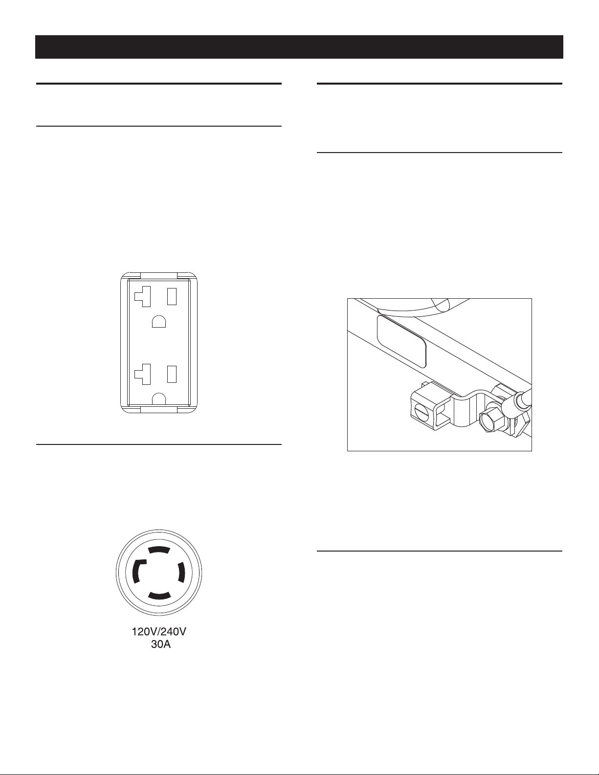
2.3.1 120 VAC, 20 Amp, Duplex Receptacle ...............6
2.3.2 120/240 VAC, 30 Amp, Receptacle ....................6
2.4 How to Use the Generator ..............................................6
2.4.1 Grounding the Generator ....................................6
2.4.2 Connecting Electrical Loads ...............................6
2.5 Don’t Overload the Generator ..........................................7
2.6 Wattage Reference Guide ...............................................7
2.7 Before Starting the Generator .........................................7
2.7.1 Adding Engine Oil ..............................................7
2.7.2 Adding Gasoline .................................................8
2.8 Starting Pull Start Engines ..............................................8
2.9 Starting Electric Start Engines ........................................9
2.10 Stopping the Engine .......................................................9
2.11 Low Oil Level Shutdown System ....................................9
2.11.1 Sensing Low Oil Level ........................................9
Maintenance ........................................................... 9
3.1 Maintenance Schedule ...................................................9
3.2 Product Specifications ..................................................10
3.2.1 Generator Specifications ..................................10
3.2.2 Engine Specifications .......................................10
3.2.3 Emissions Information .....................................10
3.3 General Recommendations ...........................................10
3.3.1 Generator Maintenance ....................................10
3.3.2 To Clean the Generator .....................................10
3.3.3 Engine Maintenance .........................................10
3.3.4 Checking Oil Level ...........................................11
3.3.5 Changing the Oil ..............................................11
3.3.6 Replacing the Spark Plug .................................11
3.4 Service Air Filter ...........................................................11
3.5 Valve Clearance ............................................................11
3.6 General ........................................................................12
3.7 Long Term Storage .......................................................12
3.8 Other Storage Tips .......................................................12
Troubleshooting .................................................... 13
4.1 Troubleshooting Guide ..................................................13
Notes .................................................................... 14
Warranty ............................................................... 16
Manual del propietario ............................. 19
Manuel d'entretien .................................... 37
Page 3

INTRODUCTION
Thank you for purchasing this model by Generac Power Systems,
Inc. This model is a compact, high performance, air-cooled,
engine driven generator designed to supply electrical power to
operate electrical loads where no utility power is available or in
place of utility due to a power outage.
READ THIS MANUAL THOROUGHLY
If any portion of this manual is not understood, contact the
nearest Authorized Dealer for starting, operating and servicing
procedures.
The operator is responsible for proper and safe use of the
equipment. We strongly recommend that the operator read this
manual and thoroughly understand all instructions before using the
equipment. We also strongly recommend instructing other users to
properly start and operate the unit. This prepares them if they need
to operate the equipment in an emergency.
The generator can operate safely, efficiently and reliably only if it
is properly located, operated and maintained. Before operating or
servicing the generator:
Become familiar with and strictly adhere to all local, state and •
national codes and regulations.
Study all safety warnings in this manual and on the product •
carefully.
Become familiar with this manual and the unit before use.•
The manufacturer cannot anticipate every possible circumstance
that might involve a hazard. The warnings in this manual, and on
tags and decals affixed to the unit are, therefore, not all inclusive.
If using a procedure, work method or operating technique that the
manufacturer does not specifically recommend, ensure that it is
safe for others. Also make sure the procedure, work method or
operating technique utilized does not render the generator unsafe.
THE INFORMATION CONTAINED HEREIN WAS BASED ON
MACHINES IN PRODUCTION AT THE TIME OF PUBLICATION.
GENERAC RESERVES THE RIGHT TO MODIFY THIS MANUAL AT
ANY TIME.
SAFETY RULES
Throughout this publication, and on tags and decals affixed to the
generator, DANGER, WARNING, CAUTION and NOTE blocks are
used to alert personnel to special instructions about a particular
operation that may be hazardous if performed incorrectly or
carelessly. Observe them carefully. Their definitions are as
follows:
INDICATES A HAZARDOUS SITUATION OR ACTION WHICH, IF
NOT AVOIDED, WILL RESULT IN DEATH OR SERIOUS INJURY.
Indicates a hazardous situation or action which, if not
avoided, could result in death or serious injury.
Introduction
Indicates a hazardous situation or action which, if not
avoided, could result in minor or moderate injury.
NOTE:
Notes contain additional information important to a procedure
and will be found within the regular text body of this manual.
These safety warnings cannot eliminate the hazards that they
indicate. Common sense and strict compliance with the special
instructions while performing the action or service are essential to
preventing accidents.
Four commonly used safety symbols accompany the DANGER,
WARNING and CAUTION blocks. The type of information each
indicates is as follows:
This symbol points out important safety
n
information that, if not followed, could
endanger personal safety and/or property of
others.
This symbol points out potential explosion
hazard.
This symbol points out potential fire hazard.
This symbol points out potential electrical
shock hazard.
GENERAL HAZARDS
Never operate in an enclosed area or indoors. •
For safety reasons, the manufacturer recommends that the •
maintenance of this equipment is carried out by an Authorized
Dealer. Inspect the generator regularly, and contact the nearest
Authorized Dealer for parts needing repair or replacement.
Operate generator only on level surfaces and where it will not be •
exposed to excessive moisture, dirt, dust or corrosive vapors.
Keep hands, feet, clothing, etc., away from drive belts, fans, •
and other moving parts. Never remove any fan guard or shield
while the unit is operating.
Certain parts of the generator get extremely hot during •
operation. Keep clear of the generator until it has cooled to
avoid severe burns.
Do NOT operate generator in the rain.•
Do not alter the construction of the generator or change •
controls which might create an unsafe operating condition.
Never start or stop the unit with electrical loads connected •
to receptacles AND with connected devices turned ON. Start
the engine and let it stabilize before connecting electrical
loads. Disconnect all electrical loads before shutting down the
generator.
Do not insert objects through unit’s cooling slots.•
When working on this equipment, remain alert at all times. •
Never work on the equipment when physically or mentally
fatigued.
1
Page 4
Safety Rules
Never use the generator or any of its parts as a step. Stepping •
on the unit can stress and break parts, and may result in
dangerous operating conditions from leaking exhaust gases,
fuel leakage, oil leakage, etc.
On electric start models, disconnect the POSITIVE (+) battery •
cable from the engine starter OR the NEGATIVE (-) battery
cable from the battery terminal, whichever is easier, before
transporting the generator.
NOTE:
This generator is equipped with a spark arrestor muffler. The
spark arrestor must be maintained in effective working order
by the owner/ operator. In the State of California, a spark
arrestor is required by law (Section 4442 of the California
Public Resources Code). Other states may have similar laws.
Federal laws apply on federal lands.
EXHAUST & LOCATION HAZARDS
Never operate in an enclosed area or indoors! • NEVER use in
the home, or in partly enclosed areas such as garages, even
if doors and windows are open! ONLY use outdoors and far
from open windows, doors, vents, and in an area that will not
accumulate deadly exhaust.
ELECTRICAL HAZARDS
The • generator produces dangerously high voltage when in
operation. Avoid contact with bare wires, terminals, connections,
etc., while the unit is running, even on equipment connected
to the generator. Ensure all appropriate covers, guards and
barriers are in place before operating the generator.
Never handle any kind of electrical cord or device while •
standing in water, while barefoot or while hands or feet are wet.
DANGEROUS ELECTRICAL SHOCK MAY RESULT.
The National Electric Code (NEC) requires the frame and external •
electrically conductive parts of the generator be properly
connected to an approved earth ground. Local electrical codes
may also require proper grounding of the generator. Consult
with a local electrician for grounding requirements in the area.
Use a ground fault circuit interrupter in any damp or highly •
conductive area (such as metal decking or steel work).
Do not use worn, bare, frayed or otherwise damaged electrical •
cord sets with the generator.
Before performing any maintenance on the generator, disconnect •
the engine starting battery (if equipped) to prevent accidental
start up. Disconnect the cable from the battery post indicated
by a NEGATIVE, NEG or (–) first. Reconnect that cable last.
In case of accident caused by electric shock, immediately shut •
down the source of electrical power. If this is not possible,
attempt to free the victim from the live conductor. AVOID
DIRECT CONTACT WITH THE VICTIM. Use a non-conducting
implement, such as a rope or board, to free the victim from the
live conductor. If the victim is unconscious, apply first aid and
get immediate medical help.
The engine exhaust fumes contain carbon monoxide, which •
can you cannot see or smell. This poisonous gas, if breathed
in sufficient concentrations, can cause unconsciousness or
even death.
Adequate, unobstructed flow of cooling and ventilating air •
is critical to correct generator operation. Do not alter the
installation or permit even partial blockage of ventilation
provisions, as this can seriously affect safe operation of the
generator. The generator MUST be operated outdoors.
This exhaust system must be properly maintained. Do nothing •
that might render the exhaust system unsafe or in noncompliance
with any local codes and/or standards.
Always use a battery operated carbon monoxide alarm indoors, •
installed according to the manufacturers instructions.
If you start to feel sick, dizzy, or weak after the generator has •
been running, move to fresh air IMMEDIATELY. See a doctor, as
you could have carbon monoxide poisoning.
FIRE HAZARDS
Gasoline is highly FLAMMABLE and its vapors are EXPLOSIVE• .
Do not permit smoking, open flames, sparks or heat in the
vicinity while handling gasoline.
Never add fuel while unit is running or hot. Allow engine to cool •
completely before adding fuel.
Never fill fuel tank indoors. • Comply with all laws regulating
storage and handling of gasoline.
Do not overfill the fuel tank. Always allow room for fuel •
expansion. If tank is over-filled, fuel can overflow onto a hot
engine and cause FIRE or an EXPLOSION. Never store generator
with fuel in tank where gasoline vapors might reach an open
flame, spark or pilot light (as on a furnace, water heater or
clothes dryer). FIRE or EXPLOSION may result. Allow unit to
cool entirely before storage.
Wipe up any fuel or oil spills immediately. Ensure that no •
combustible materials are left on or near the generator. Keep the
area surrounding the generator clean and free from debris and
keep a clearance of five (5) feet on all side to allow for proper
ventilation of the generator.
2
Page 5
Do not insert objects through unit’s cooling slots.•
Do not • operate the generator if connected electrical devices
overheat, if electrical output is lost, if engine or generator sparks
or if flames or smoke are observed while unit is running.
Keep a fire extinguisher near the generator at all times. •
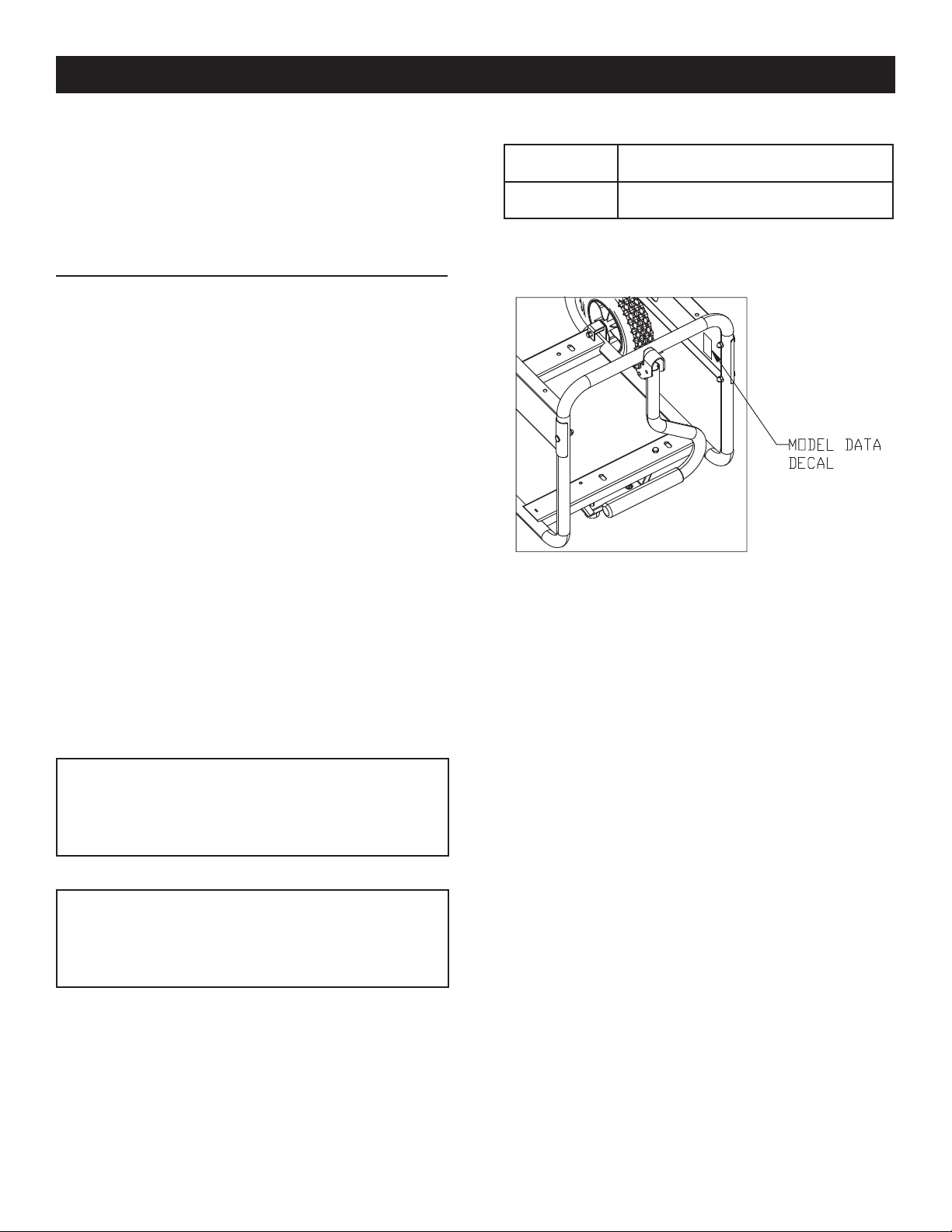
Safety Rules
MODEL NO:
SERIAL NO:
STANDARDS INDEX
In the absence of pertinent standards, codes, regulations and laws,
the published information listed below may be used as a guideline
for operation of this equipment. Always reference the latest revision
available for the standards listed.
1. NFPA No. 70, NFPA HANDBOOK OF NATIONAL ELECTRIC
CODE.
2. Article X, NATIONAL BUILDING CODE, available from the
American Insurance Association, 85 John Street, New York,
N.Y. 10038.
3. AGRICULTURAL WIRING HANDBOOK, available from the Food
and Energy Council, 909 University Avenue, Columbia, MO
65201.
4. ASAE EP-3634, INSTALLATION AND MAINTENANCE OF
FARM STANDBY ELECTRICAL SYSTEMS, available from the
American Society of Agricultural Engineers, 2950 Niles Road,
St. Joseph, MI 49085.
Unit ID Location
CALIFORNIA PROPOSITION 65 WARNING
Engine exhaust and some of its constituents are known
to the State of California to cause cancer, birth defects
and other reproductive harm.
CALIFORNIA PROPOSITION 65 WARNING
This product contains or emits chemicals known to the
State of California to cause cancer, birth defects and
other reproductive harm.
3
Page 6
General Information
1.1 UNPACKING
Remove all packaging material.•
Remove separate accessory box.•
Remove the generator from carton.•
1.1.1 ACCESSORY BOX
Check all contents. If any parts are missing or damaged, locate an
authorized dealer at 1-888-436-3722.
1 - Owner’s Manual • 1 - Handle Assembly•
1 - Liter Oil SAE 30 • 1 - Frame Foot•
2 - Never-Flat Wheels • 1 - Battery Charger (electric •
start only)
1 - Hardware Bag (containing the following):•
• 2-Rubber Feet • 2-M8 Bolt (Long)
• 2-1/2” Axle Pins • 2-M8 Bolts (Short)
• 2-Cotter Pins • 2-M8 Acorn Nut
• 2-1/2” Flat Washers • 4-Hex Flanged M8 Nuts
1.2 ASSEMBLY
The generator requires some assembly prior to using it. If problems
arise when assembling the generator, please call the Generator
Helpline at 1-888-77LOWES.
1.2.1 ASSEMBLING THE ACCESSORY KIT
The wheels are designed into the unit to greatly improve the
portability of the generator.
You will need the following tools to properly install the accessory
kit.
Needle Nose Pliers•
Ratchet and a 13mm (1/2”) socket •
13mm (1/2”) box wrench•
NOTE:
The wheels are not intended for over-the-road use.
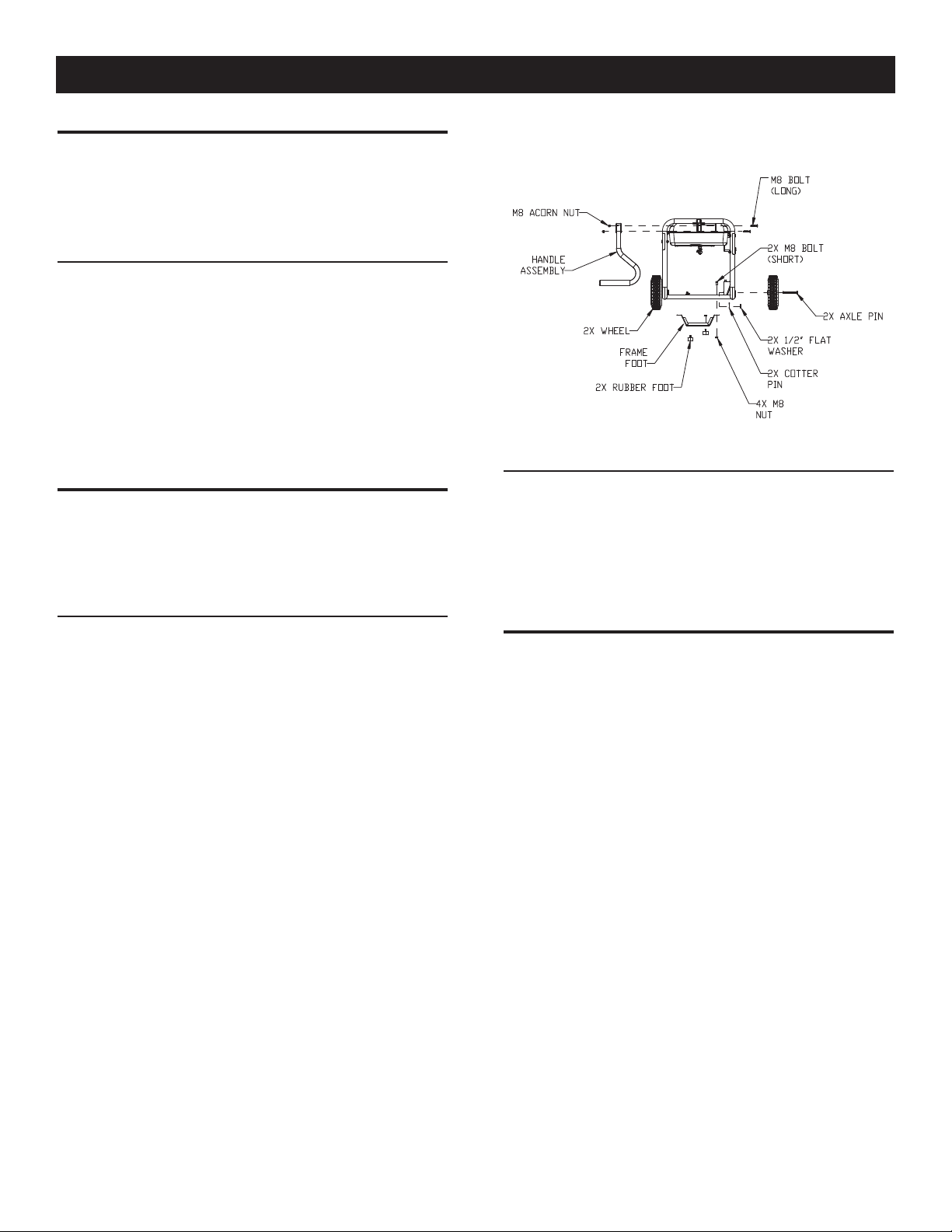
1. Refer to Figure 1 and install the Wheels as follows:
• Slide the Axle Pins through the Wheel, 1/2" Flat Washer, and Wheel
Bracket on the frame.
• Insert the Cotter Pin through the Axle Pin then bend the tabs (of the
Cotter Pins) outward to lock into place.
2. Refer to Figure 1 and install the Frame Foot and Rubber
Bumpers as shown.
• Slide the Rubber Bumper studs through the Frame Foot then install
the Locking Flange Nuts.
• Slide the Hex Head Bolts through the holes in the Frame Rail.
• Slide the Frame Foot onto the Hex Head Bolts then install the
Locking Flange Nuts.
3. Refer to Figure 1 and install the Handle as shown.
• Slide the long Bolts through the Handle Bracket and Handle, then
install the Hex Nuts.
Figure 1 – Wheel & Handle Assembly
1.2.2 STARTER CONNECTION (ELECTRIC START ONLY)
The unit has been deliberately shipped with the starter cable
disconnected.
To connect starter:
1. Locate starter cable.
2. Pull vinyl boot back onto starter cable.
3. Remove nut and washer from starter post.
4. Put starter cable onto post and re-install washer and nut.
2.1 KNOW THE GENERATOR
Read the Owner’s Manual and Safety Rules before operating
this generator.
Compare the generator to Figures 2 through 4 to become
familiarized with the locations of various controls and adjustments.
Save this manual for future reference.
1. 120 Volt AC, 20 Amp, Duplex Receptacle – Supplies electrical
power for the operation of 120 Volt AC, 20 Amp, single-phase,
60 Hz electrical lighting, appliance, tool and motor loads.
2. 120/240 Volt AC, 30 Amp Locking Receptacle – Supplies
electrical power for the operation of 120 and/or 240 Volt AC,
30 Amp, single-phase, 60 Hz, electrical lighting, appliance,
tool and motor loads.
3. Circuit Breakers (AC) – Each receptacle is provided with a
push-to-reset circuit breaker to protect the generator against
electrical overload.
4. Oil Drain – Use to drain engine oil.
5. Air Filter – Filters intake air as it is drawn into the engine.
6. Choke Knob – Used when starting a cold engine.
7. Fuel Tank – See generator Specifications for tank capacity.
8. Grounding Lug – Ground the generator to an approved earth
ground here. See "Grounding the Generator" for details.
9. Run/Stop Switch – Controls the operation of the generator
(pull start models only).
9A. Start Switch – Used to start engine from the starter motor
(electric start models only).
10. Muffler – Quiets the engine.
4
Page 7

Operation
Figure 2 - Control Panel
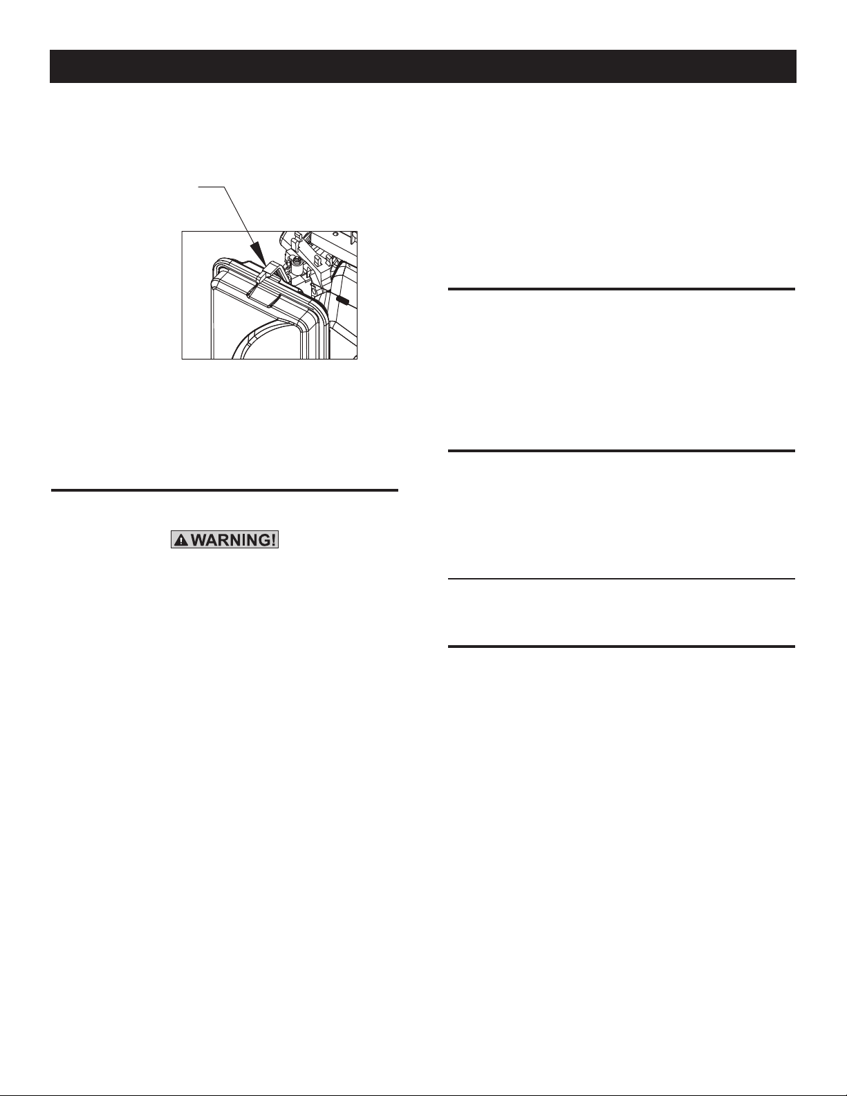
11. Handle – Pivot and retract for storage. Press the springloaded button to move handles.
12. Gas Cap – Fuel fill location.
13. Fuel Gauge – Shows fuel level in tank.
14. Oil Fill – Add oil here.
15. Recoil Starter – Use to start engine manually.
16. Fuel Shut Off – Valve between fuel tank and carburetor.
17. Battery Charger Input – This receptacle allows the capability
to recharge the 12 volt DC storage battery provided with
the 12 Volt Adaptor Plug Charger which is included in the
Accessory Box. Located behind the battery charger input is
a 1.50 Amp in-line fuse which is inside the control panel to
protect the batter (electric start only).
18. Battery – Powers the electric starter (electric start only).
19. Hourmeter – Tracks hours of operation.
Figure 3 - Generator Controls
Figure 4 - Generator Controls
2.2 HOURMETER
The Hourmeter tracks hours of operation for scheduled
maintenance:
There will be a "CHG OIL" message every 100 hours. The message
will flash one hour before and one hour after each 100 hour
interval, providing a two hour window to perform service.
This message will actually begin flashing at 99 hours and disable
itself at 101 hours again, providing a two hour window to perform
the service.
Every 200 hours the "SVC" icon on the lower left hand corner of
the display will flash. The message will flash one hour before and
one hour after each 200 hour interval providing a two hour window
to perform service.
When the hour meter is in the Flash Alert mode, the maintenance
message will always alternate with elapsed time in hours and
tenths. The hours will flash four times, then alternate with the
maintenance message four times until the meter resets itself.
100 hours - CHG OIL — Oil Change Interval (Every 100 hrs)•
5
Page 8
Operation
2.3 CORD SETS AND CONNECTION PLUGS
2.3.1 120 VAC, 20 AMP, DUPLEX RECEPTACLE
This is a 120 Volt outlet protected against overload by a 20 Amp
push-to-reset circuit breaker (Figure 5). Use each socket to power
120 Volt AC, single phase, 60 Hz electrical loads requiring up to a
combined 2400 watts (2.4 kW) or 20 Amps of current. Use only
high quality, well-insulated, 3-wire grounded cord sets rated for
125 Volts at 20 Amps (or greater).
Keep extension cords as short as possible, preferably less than
15 feet long, to prevent voltage drop and possible overheating of
wires.
Figure 5 - 120 Volt AC, 20 Amp, Duplex Receptacle
2.4 HOW TO USE THE GENERATOR
If there are any problems operating the generator, please call the
generator helpline at 1-888-436-3722.
2.4.1 GROUNDING THE GENERATOR
The National Electrical Code requires that the frame and
external electrically conductive parts of this generator be
properly connected to an approved earth ground (Figure 7).
Local electrical codes may also require proper grounding of the
unit. For that purpose, connecting a No. 10 AWG (American Wire
Gauge) stranded copper wire to the grounding lug and to an
earth-driven copper or brass grounding rod (electrode) provides
adequate protection against electrical shock. However, local codes
may vary widely. Consult with a local electrician for grounding
requirements in the area.
Figure 7 - Grounding the Generator
2.3.2 120/240 VAC, 30 AMP RECEPTACLE
Use a NEMA L14-30 plug with this receptacle (rotate to lock/
unlock). Connect a suitable 4-wire grounded cord set to the plug
and to the desired load. The cord set should be rated for 250 Volts
AC at 30 Amps (or greater) (Figure 6).
Figure 6 - 120/240 VAC, 30 Amp Receptacle
Use this receptacle to operate 120 Volt AC, 60 Hz, single phase
loads requiring up to 3600 watts (3.6 kW) of power at 30 Amps
or 240 Volt AC, 60 Hz, single phase loads requiring up to 7200
watts (7.2 kW) of power at 30 Amps. The outlet is protected by
two 25 Amp (5.0/5.5kW) or two 30 Amp (6.5kW) push-to-reset
circuit breakers.
Proper grounding of the generator will help prevent electrical
shock in the event of a ground fault condition in the generator
or in connected electrical devices. Proper grounding also helps
dissipate static electricity, which often builds up in ungrounded
devices.
2.4.2 CONNECTING ELECTRICAL LOADS
DO NOT connect 240 Volt loads to 120 Volt receptacles. DO NOT
connect 3-phase loads to the generator. DO NOT connect 50 Hz
loads to the generator.
Let engine stabilize and warm up for a few minutes after •
starting.
Plug in and turn on the desired 120 or 240 Volt AC, single •
phase, 60 Hz electrical loads.
Add up the rated watts (or amps) of all loads to be connected •
at one time. This total should not be greater than (a) the rated
wattage/amperage capacity of the generator or (b) circuit
breaker rating of the receptacle supplying the power. See "Don't
Overload the Generator".
6
Page 9
10 W- 30
SA E 30
Sy nt he ti c 5W -3 0
Operation
2.5 DON’T OVERLOAD THE GENERATOR
Overloading a generator in excess of its rated wattage capacity
can result in damage to the generator and to connected electrical
devices. Observe the following to prevent overloading the unit:
Add up the total wattage of all electrical devices to be connected •
at one time. This total should NOT be greater than the
generator's wattage capacity.
The rated wattage of lights can be taken from light bulbs. The •
rated wattage of tools, appliances and motors can usually be
found on a data label or decal affixed to the device.
If the appliance, tool or motor does not give wattage, multiply •
volts times ampere rating to determine watts (volts x amps =
watts).
Some electric motors, such as induction types, require about •
three times more watts of power for starting than for running.
This surge of power lasts only a few seconds when starting
such motors. Make sure to allow for high starting wattage when
selecting electrical devices to connect to the generator:
1. Figure the watts needed to start the largest motor.
2. Add to that figure the running watts of all other connected
loads.
The Wattage Reference Guide is provided to assist in determining
how many items the generator can operate at one time.
NOTE:
All figures are approximate. See data label on appliance for
wattage requirements.
2.6 WATTAGE REFERENCE GUIDE
Device . . . . . . . . . . . . . . . . . . . . . . . . . . . . . . . . . . . Running Watts
*Air Conditioner (12,000 Btu). . . . . . . . . . . . . . . . . . . . . . . . . . 1700
*Air Conditioner (24,000 Btu). . . . . . . . . . . . . . . . . . . . . . . . . . 3800
*Air Conditioner (40,000 Btu). . . . . . . . . . . . . . . . . . . . . . . . . . 6000
Battery Charger (20 Amp). . . . . . . . . . . . . . . . . . . . . . . . . . . . . . 500
Belt Sander (3") . . . . . . . . . . . . . . . . . . . . . . . . . . . . . . . . . . . . 1000
Chain Saw . . . . . . . . . . . . . . . . . . . . . . . . . . . . . . . . . . . . . . . . 1200
Circular Saw (6-1/2") . . . . . . . . . . . . . . . . . . . . . . . . . . .800 to 1000
*Clothes Dryer (Electric) . . . . . . . . . . . . . . . . . . . . . . . . . . . . . 5750
*Clothes Dryer (Gas) . . . . . . . . . . . . . . . . . . . . . . . . . . . . . . . . . 700
*Clothes Washer . . . . . . . . . . . . . . . . . . . . . . . . . . . . . . . . . . . 1150
Coffee Maker . . . . . . . . . . . . . . . . . . . . . . . . . . . . . . . . . . . . . . 1750
*Compressor (1 HP). . . . . . . . . . . . . . . . . . . . . . . . . . . . . . . . . 2000
*Compressor (3/4 HP) . . . . . . . . . . . . . . . . . . . . . . . . . . . . . . . 1800
*Compressor (1/2 HP) . . . . . . . . . . . . . . . . . . . . . . . . . . . . . . . 1400
Curling Iron. . . . . . . . . . . . . . . . . . . . . . . . . . . . . . . . . . . . . . . . . 700
*Dehumidifier . . . . . . . . . . . . . . . . . . . . . . . . . . . . . . . . . . . . . . . 650
Disc Sander (9"). . . . . . . . . . . . . . . . . . . . . . . . . . . . . . . . . . . . 1200
Edge Trimmer . . . . . . . . . . . . . . . . . . . . . . . . . . . . . . . . . . . . . . . 500
Electric Blanket . . . . . . . . . . . . . . . . . . . . . . . . . . . . . . . . . . . . . . 400
Electric Nail Gun . . . . . . . . . . . . . . . . . . . . . . . . . . . . . . . . . . . . 1200
Electric Range (per element). . . . . . . . . . . . . . . . . . . . . . . . . . . 1500
Electric Skillet . . . . . . . . . . . . . . . . . . . . . . . . . . . . . . . . . . . . . . 1250
*Freezer . . . . . . .. . . . . . . . . . . . . . . . . . . . . . . . . . . . . . . . . . . ..700
*Furnace Fan (3/5 HP) . . . . . . . . . . . . . . . . . . . . . . . . . . . . . . . . 875
*Garage Door Opener . . . . . . . . . . . . . . . . . . . . . . . . . . . .500 to 750
Hair Dryer. . . . . . . . . . . . . . . . . . . . . . . . . . . . . . . . . . . . . . . . . 1200
Hand Drill . . . . . . . . . . . . . . . . . . . . . . . . . . . . . . . . . . . .250 to 1100
Hedge Trimmer. . . . . . . . . . . . . . . . . . . . . . . . . . . . . . . . . . . . . . 450
Impact Wrench . . . . . . . . . . . . . . . . . . . . . . . . . . . . . . . . . . . . . . 500
Iron. . . . . . . . . . . . . . . . . . . . . . . . . . . . . . . . . . . . . . . . . . . . . . 1200
*Jet Pump . . . . . . . . . . . . . . . . . . . . . . . . . . . . . . . . . . . . . . . . . 800
Lawn Mower. . . . . . . . . . . . . . . . . . . . . . . . . . . . . . . . . . . . . . . 1200
Light Bulb . . . . . . . . . . . . . . . . . . . . . . . . . . . . . . . . . . . . . . . . . . 100
Microwave Oven . . . . . . . . . . . . . . . . . . . . . . . . . . . . . . .700 to 1000
*Milk Cooler . . . . . . . . . . . . . . . . . . . . . . . . . . . . . . . . . . . . . . . 1100
Oil Burner on Furnace . . . . . . . . . . . . . . . . . . . . . . . . . . . . . . . . . 300
Oil Fired Space Heater (140,000 Btu) . . . . . . . . . . . . . . . . . . . . . 400
Oil Fired Space Heater (85,000 Btu) . . . . . . . . . . . . . . . . . . . . . . 225
Oil Fired Space Heater (30,000 Btu) . . . . . . . . . . . . . . . . . . . . . . 150
*Paint Sprayer, Airless (1/3 HP) . . . . . . . . . . . . . . . . . . . . . . . . . 600
Paint Sprayer, Airless (handheld). . . . . . . . . . . . . . . . . . . . . . . . . 150
Radio . . . . . . . . . . . . . . . . . . . . . . . . . . . . . . . . . . . . . . . . .50 to 200
*Refrigerator. . . . . . . . . . . . . . . . . . . . . . . . . . . . . . . . . . . . . . . . 700
Slow Cooker . . . . . . . . . . . . . . . . . . . . . . . . . . . . . . . . . . . . . . . . 200
*Submersible Pump (1-1/2 HP) . . . . . . . . . . . . . . . . . . . . . . . . 2800
*Submersible Pump (1 HP) . . . . . . . . . . . . . . . . . . . . . . . . . . . 2000
*Submersible Pump (1/2 HP) . . . . . . . . . . . . . . . . . . . . . . . . . . 1500
*Sump Pump . . . . . . . . . . . . . . . . . . . . . . . . . . . . . . . . .800 to 1050
*Table Saw (10") . . . . . . . . . . . . . . . . . . . . . . . . . . . . .1750 to 2000
Television . . . . . . . . . . . . . . . . . . . . . . . . . . . . . . . . . . . . .200 to 500
Toaster . . . . . . . . . . . . . . . . . . . . . . . . . . . . . . . . . . . . .1000 to 1650
Weed Trimmer . . . . . . . . . . . . . . . . . . . . . . . . . . . . . . . . . . . . . . 500
* Allow 3 times the listed watts for starting these devices.
2.7 BEFORE STARTING THE GENERATOR
Prior to operating the generator, engine oil and gasoline will need
to be added, as follows:
2.7.1 ADDING ENGINE OIL
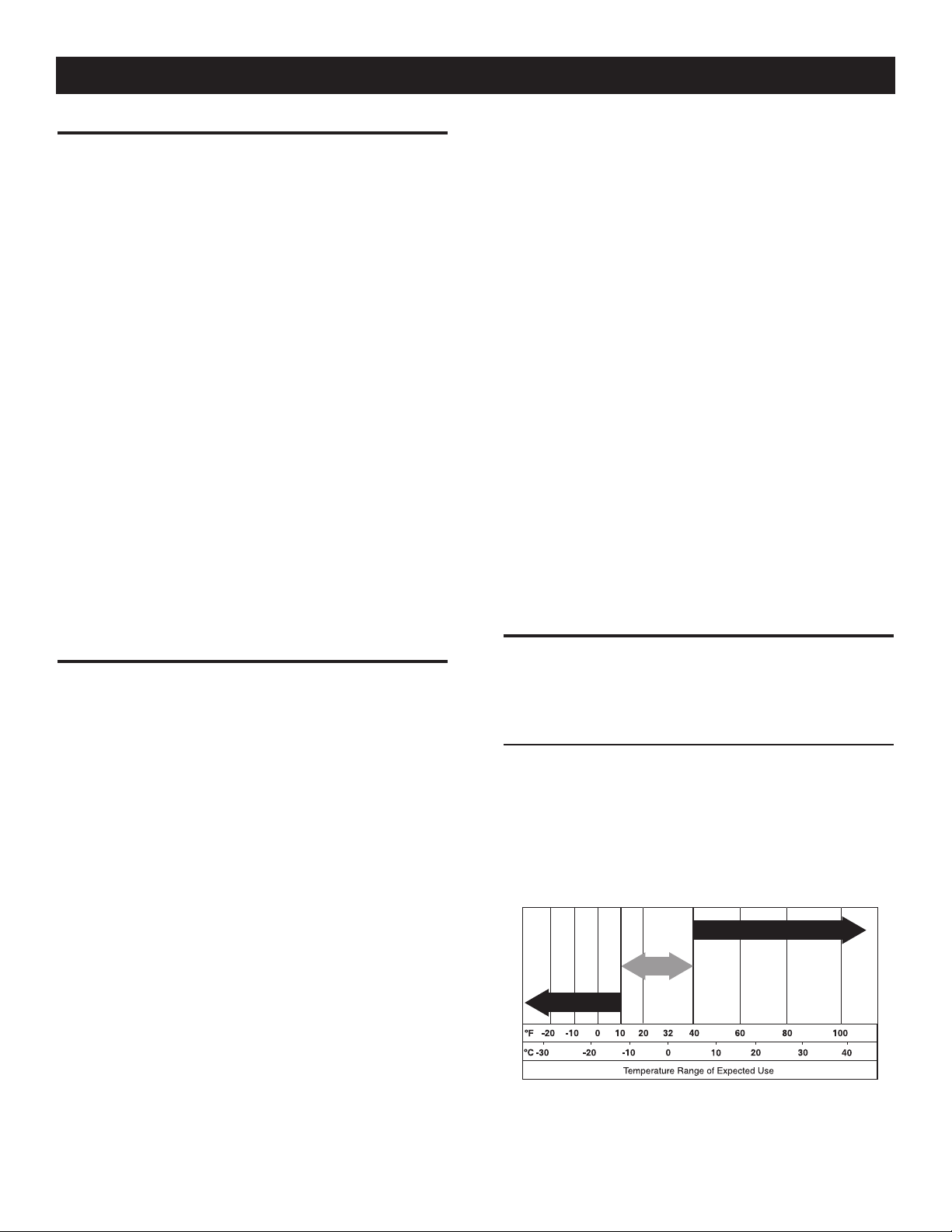
All oil should meet minimum American Petroleum Institute (API)
Service Class SJ, SL or better. Use no special additives. Select
the oil's viscosity grade according to the expected operating
temperature (also see chart).
Above 40° F, use SAE 30•
Below 40° F and down to 10° F, use 10W-30•
Below 10° F, use synthetic 5W-30•
SAE 30
10W-30
Synthetic 5W-30
7
Page 10
Operation
Any attempt to crank or start the engine
before it has been properly serviced with the
n
recommended oil may result in an engine
failure.
Place generator on a level surface.•
Clean area around oil fill and remove oil fill cap and dipstick.•
Wipe dipstick clean.•
Slowly fill engine with oil through the oil fill opening until it •
reaches the full mark. Stop filling occasionally to check oil level.
Be careful not to over fill.
Install oil fill cap and finger tighten securely.•
Check engine oil level before starting each time thereafter.•
2.7.2 ADDING GASOLINE
Never fill fuel tank indoors. Never fill fuel tank
when engine is running or hot. Avoid spilling
gasoline on a hot engine. Allow engine to cool
entirely before filling fuel tank. DO NOT light a
cigarette or smoke when filling the fuel tank.
Do not overfill the fuel tank. Always leave room
for fuel expansion. If the fuel tank is overfilled,
fuel can overflow onto a hot engine and cause
FIRE or EXPLOSION. Wipe up any spilled fuel
immediately.
Do not light a cigarette ro smoke whin filling the
fuel tank. Gasoline is highly FLAMMABLE and
its vapors are EXPLOSIVE.
Use regular UNLEADED gasoline with the generator engine. Do •
not use any gasoline with more than 10% added ethanol. Do not
use E85 gasoline. Do not mix oil with gasoline.
Clean area around fuel fill cap, remove cap.•
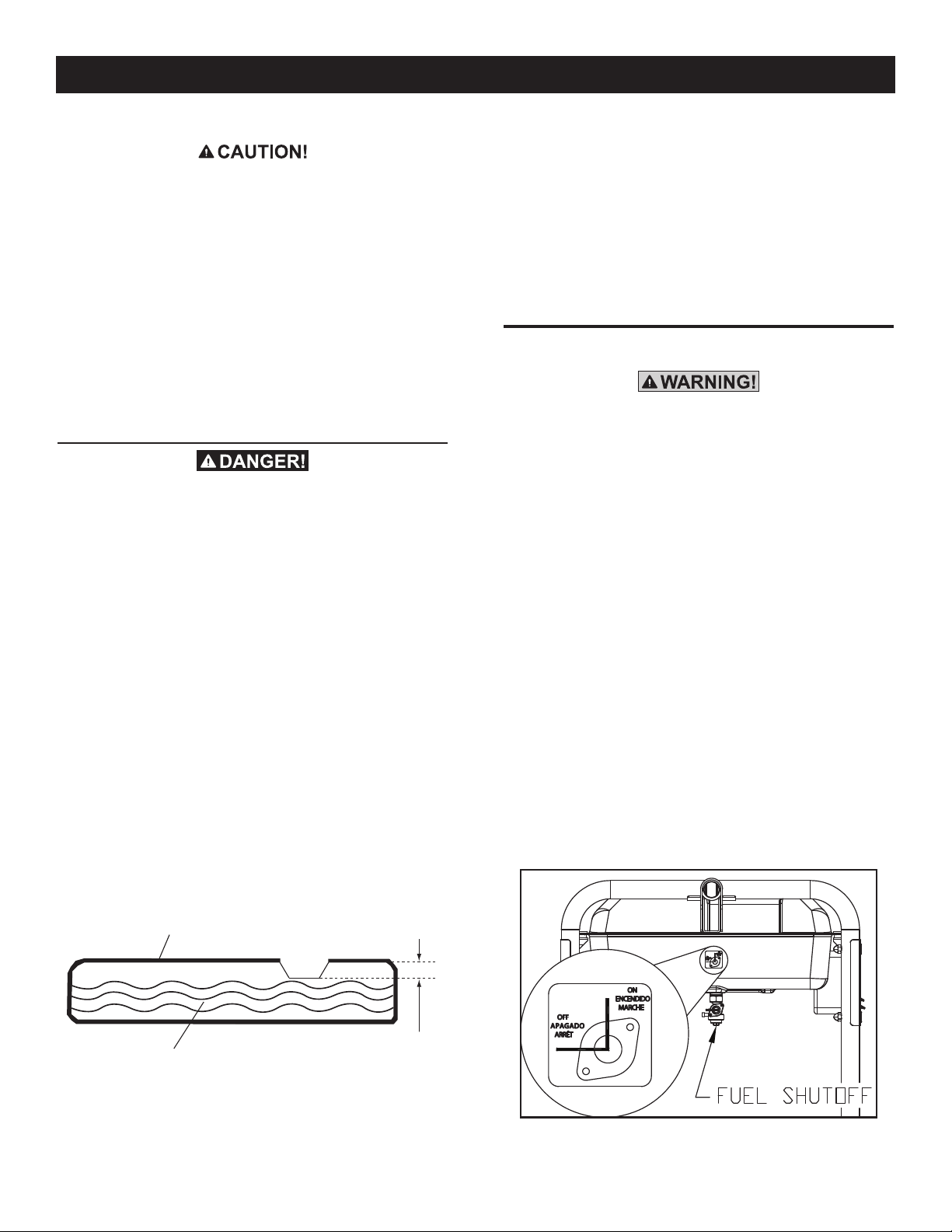
Slowly add unleaded regular gasoline to fuel tank. Fill to bottom •
of screen filter. Be careful not to overfill (Figure 8).
Install fuel cap and wipe up any spilled gasoline. •
IMPORTANT: It is important to prevent gum deposits from forming
in fuel system parts such as the carburetor, fuel hose or tank
during storage. Alcohol-blended fuels (called gasohol, ethanol
or methanol) can attract moisture, which leads to separation and
formation of acids during storage. Acidic gas can damage the fuel
system of an engine while in storage. To avoid engine problems,
the fuel system should be emptied before storage of 30 days or
longer. See the "Storage" section. Never use engine or carburetor
cleaner products in the fuel tank as permanent damage may
occur.
2.8 STARTING PULL START ENGINES
Never start or stop engine with electrical
devices plugged into the receptacles AND
devices turned on.
Unplug all electrical loads from the unit's receptacles before •
starting the engine.
Make sure the unit is in a level position.•
OPEN• the Fuel Shut-off Valve (Figure 9).
Turn engine RUN/STOP switch to • ON position.
Slide engine choke to the LEFT to FULL CHOKE position (Figure •
10).
To start engine, firmly grasp the recoil handle and pull slowly •
until increased resistance is felt. Pull rapidly up and away.
When engine starts, move choke knob to • 1/2-CHOKE position
until engine runs smoothly and then fully into RUN position. If
engine falters, move choke back out to 1/2-CHOKE position
until engine runs smoothly and then to RUN position.
NOTE:
If engine fires, but does not continue to run, move choke lever
to FULL CHOKE and repeat starting instructions.
Figure 9 - Fuel Shut-off Valve
8
Figure 8 - Fuel Tank
Fuel Tank
Fuel
DO NOT Fill Above Lip
Page 11
Maintenance
Figure 10 - Choke Position
CHOKE LEVER
LEFT = CHOKE
RIGHT = RUN
IMPORTANT: Do not overload the generator. Also, do not overload
individual panel receptacles. These outlets are protected against
overload with push-to-reset-type circuit breakers. If amperage
rating of any circuit breaker is exceeded, that breaker opens and
electrical output to that receptacle is lost. Read “Don’t Overload the
Generator” carefully.
2.9 STARTING ELECTRIC START ENGINES
NOTE:
If engine fires, but does not continue to run, move choke lever
to FULL CHOKE and repeat starting instructions.
IMPORTANT: Do not overload the generator. Also, do not overload
individual panel receptacles. These outlets are protected against
overload with push-to-reset-type circuit breakers. If amperage
rating of any circuit breaker is exceeded, that breaker opens and
electrical output to that receptacle is lost. Read “Don’t Overload the
Generator” carefully.
2.10 STOPPING THE ENGINE
Shut off all loads, then unplug the electrical loads from generator •
panel receptacles. Never start or stop the engine with electrical
devices plugged in and turned on.
Let engine run at no-load for several minutes to stabilize the •
internal temperatures of engine and generator.
Move Run/Stop switch to • OFF position.
Close fuel valve.•
2.11 LOW OIL LEVEL SHUTDOWN SYSTEM
The engine is equipped with a low oil level sensor that shuts down
the engine automatically when the oil level drops below a specified
level. If the engine shuts down by itself and the fuel tank has
enough gasoline, check engine oil level.
Never start or stop engine with electrical
devices plugged into the receptacles AND
devices turned on.
Unplug all electrical loads from the unit's receptacles before •
starting the engine.
Make sure the unit is in a level position.•
Open the fuel shut-off valve (Figure 9).•
Move engine CHOKE knob outward to FULL CHOKE position •
(Figure 10).
To start engine, press and hold the Start/Run/Stop switch in •
the “Start” position. The engine will crank and attempt to start.
When the engine starts, release the switch to the run position.
When the engine starts, move choke knob to “1/2 Choke” •
position until the engine runs smoothly and then fully in to the
“Run” position. If engine falters, move choke knob back out to
“1/2 Choke” position until the engine runs smoothly and then
to “Run” position.
This generator is also equipped with a manual recoil starter •
which may be used if the battery is discharged.
NOTE:
The switch must be in the RUN position.
To start manually, firmly grasp the recoil handle and pull slowly •
until increased resistance is felt. Pull rapidly up and away to
start engine. Then follow the same choke sequence.
2.11.1 SENSING LOW OIL LEVEL
If the system senses a low oil level during operation, the engine
shuts down. The engine will not run until the oil has been refilled
to the proper level.
3.1 MAINTENANCE SCHEDULE
Follow the calendar intervals. More frequent service is required
when operating in adverse conditions noted below.
Check Oil Level At Each Use
Change Oil ‡ *Every 100 hours or Every Season
Check Valve Clearance ***Every Season
Service Air Filter ** Every 200 hours or Every Season
Replace Spark Plug Every Season
‡ Change oil after first 30 hours of operation then every season.
* Change oil and oil filter every month when operating under heavy load or in high
temperatures.
** Clean more often under dirty or dusty operating conditions. Replace air filter
parts if they cannot be adequately cleaned.
*** Check valve clearance and adjust if necessary after first 50 hours of
operation and every 100 hours thereafter.
9
Page 12

Maintenance
3.2 PRODUCT SPECIFICATIONS
3.2.1 GENERATOR SPECIFICATIONS
Rated Power ...............................................................5.0/5.5/6.5 kW**
Surge Power ...............................................................6.25/6.88/8.0 kW
Rated AC Voltage ......................................................................120/240
Rated AC Load
Current @ 240V (5.0/5.5/6.5 kW) ..................20.8/22.9/27.1 Amps**
Current @ 120V (5.0/5.5/6.5 kW) ..................41.6/45.8/54.2 Amps**
Rated Frequency .................................................... 60 Hz @ 3600 RPM
Phase ................................................................................ Single Phase
** Maximum wattage and current are subject to, and limited by, such factors
as fuel Btu content, ambient temperature, altitude, engine condition, etc..
Maximum power decreases about 3.5% for each 1,000 feet above sea level;
and will also decrease about 1% for each 6° C (10° F) above 16° C (60° F)
ambient temperature.
3.2.2 ENGINE SPECIFICATIONS
Displacement .............................................................................. 389 cc
Spark Plug Type ................................ NHSP LDF7TC or Champion N9YC
Spark Plug Gap .............................0.028-0.031 inch or (0.70-0.80 mm)
Gasoline Capacity ......................................................... 7.2 U.S. gallons
Oil Type.................. See Chart in "Before Starting the Generator" Section
Oil Capacity ....................................................................1 L (1.06 Qts.)
Run Time at 50% Load (5.0/5.5/6.5 kW) ..................................10 Hours
3.3 GENERAL RECOMMENDATIONS
The warranty of the generator does not cover items that have been
subjected to operator abuse or negligence. To receive full value
from the warranty, the operator must maintain the generator as
instructed in this manual.
Some adjustments will need to be made periodically to properly
maintain the generator.
All adjustments in the Maintenance section of this manual should
be made at least once each season. Follow the requirements in the
"Maintenance Schedule".
NOTE:
Once a year replace the spark plug and replace the air filter.
A new spark plug and clean air filter assure proper fuel-air
mixture and help the engine run better and last longer.
3.3.1 GENERATOR MAINTENANCE
Generator maintenance consists of keeping the unit clean and dry.
Operate and store the unit in a clean dry environment where it will
not be exposed to excessive dust, dirt, moisture or any corrosive
vapors. Cooling air slots in the generator must not become clogged
with snow, leaves, or any other foreign material.
Check the cleanliness of the generator frequently and clean when
dust, dirt, oil, moisture or other foreign substances are visible on
its exterior surface.
3.2.3 EMISSIONS INFORMATION
The Environmental Protection Agency (EPA) requires that this
generator comply with exhaust emission standards. The engine
used in this generator is certified to meet the applicable EPA
emission levels. It is important to follow the maintenance
specifications provided in this manuals to ensure that the engine
complies with the applicable emission standards for the duration
of the engine's life. The emission control system on this generator
consists of the following:
Air Induction system • Ignition System•
~ Intake Pipe/Manifold ~ Spark Plug
~ Air Cleaner ~ Ignition Coil
Exhaust System • Fuel System•
~ Exhaust manifold ~ Carburetor
~ Muffler
The Emissions Compliance Period referred to on the Emissions
Compliance Label indicates the number of operating hours
for which the engine has been shown to meet EPA emission
requirements.
Never insert any object or tool through the air
cooling slots, even if the engine is not running.
n
NOTE:
DO NOT use a garden hose to clean generator. Water can enter
the engine fuel system and cause problems. In addition, if water
enters the generator through cooling air slots, some water will
be retained in voids and crevices of the rotor and stator winding
insulation. Water and dirt buildup on the generator internal
windings will eventually decrease the insulation resistance of
these windings.
3.3.2 TO CLEAN THE GENERATOR
Use a damp cloth to wipe exterior surfaces clean.•
A soft, bristle brush may be used to loosen caked on dirt, oil, •
etc.
A vacuum cleaner may be used to pick up loose dirt and •
debris.
Low pressure air (not to exceed 25 psi) may be used to •
blow away dirt. Inspect cooling air slots and openings
on the generator. These openings must be kept clean and
unobstructed.
3.3.3 ENGINE MAINTENANCE
10
When working on the generator, always
disconnect spark plug wire from spark plug and
keep wire away from spark plug.
Page 13
Maintenance
3.3.4 CHECKING OIL LEVEL
See the “Before Starting the Generator” section for information on
checking the oil level. The oil level should be checked before each
use, or at least every eight hours of operation. Keep the oil level
maintained.
3.3.5 CHANGING THE OIL
Change the oil after every 100 hours. If running this unit under
dirty or dusty conditions, or in extremely hot weather, change the
oil more often.
Hot oil may cause burns. Allow engine to
cool before draining oil. Avoid prolonged
n
or repeated skin exposure with used oil.
Thoroughly wash exposed areas with soap.
Use the following instructions to change the oil after the engine
cools down:
Clean area around oil drain plug.•
Remove oil drain plug from engine and oil fill plug to drain oil •
completely into a suitable container.
When oil has completely drained, install oil drain plug and •
tighten securely.
Fill engine with recommended oil. (See “Before Starting the •
Generator” for oil recommendations).
Wipe up any spilled oil.•
Dispose of used oil at a proper collection center.•
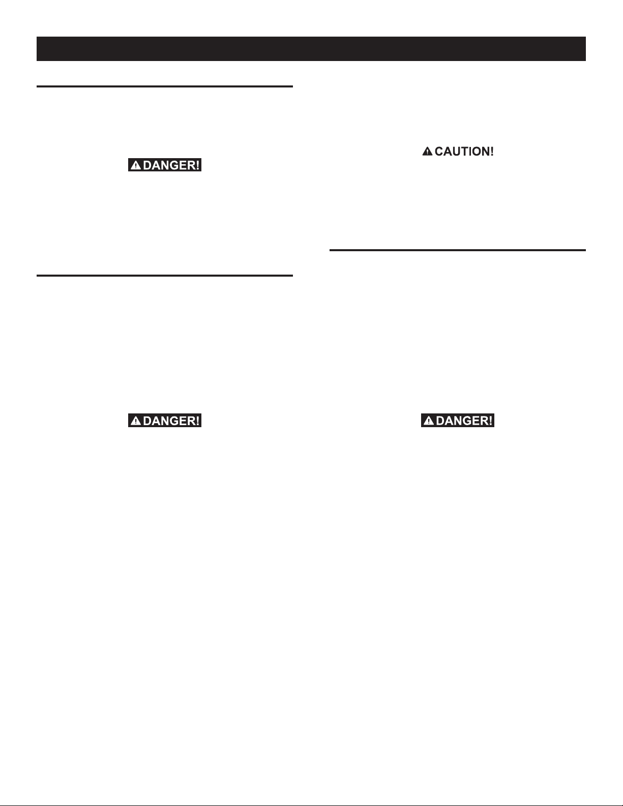
3.4 SERVICE AIR FILTER
The engine will not run properly and may be damaged if using a
dirty air filter. Clean the air filter every 200 hours or once a year
(Figure 12). Clean or replace more often if operating under dusty
conditions.
Remove air • filter cover.
Wash in soapy water. Squeeze filter dry in clean cloth (DO NOT •
TWIST).
Clean air • filter cover before re-installing it.
NOTE:
To order a new air filter, please contact the nearest authorized
service center at 1-888-436-3722.
Figure 12 - Air Filter
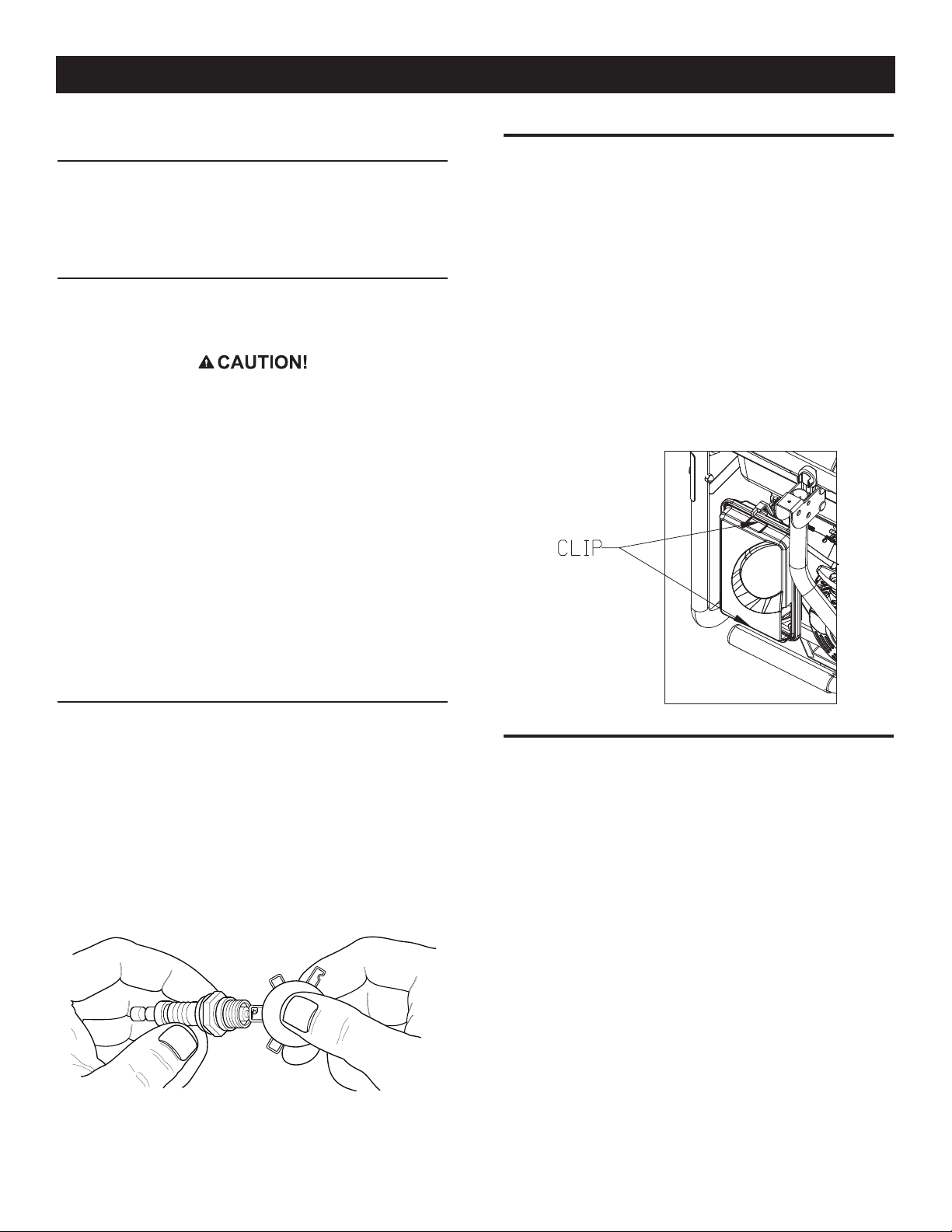
3.3.6 REPLACING THE SPARK PLUG
Use Champion N9YC spark plug or equivalent. Replace the plug
once each year. This will help the engine start easier and run
better.
1. Stop the engine and pull the spark plug wire off of the spark
plug.
2. Clean the area around the spark plug and remove it from the
cylinder head.
3. Set the spark plug's gap to 0.70-0.80 mm (0.028-0.031 in.).
Install the correctly gapped spark plug into the cylinder head
(Figure 11).
Figure 11 - Spark Plug Gap
3.5 VALVE CLEARANCE
Intake — 0.15 ± 0.02mm (cold), (0.006" ± 0.0008" inches)•
Exhaust — 0.0020 ± 0.02mm (cold) (0.008" ± 0.0008" •
inches)
After the first 50 hours of operation, check the valve clearance
in the engine and adjust if necessary.
Important: If feeling uncomfortable about doing this procedure or
the proper tools are not available, please take the generator to the
nearest service center to have the valve clearance adjusted. This is
a very important step to ensure longest life for the engine.
11
Page 14
Maintenance
3.6 GENERAL
The generator should be started at least once every seven days and
be allowed to run at least 30 minutes. If this cannot be done and
the unit must be stored for more than 30 days, use the following
information as a guide to prepare it for storage.
NEVER store engine with fuel in tank indoors
or in enclosed, poorly ventilated areas where
fumes may reach an open flame, spark or pilot
light as on a furnace, water heater, clothes dryer
or other gas appliance.
Allow unit to cool entirely before storage.
n
3.7 LONG TERM STORAGE
It is important to prevent gum deposits from forming in essential
fuel system parts such as the carburetor, fuel hose or tank during
storage. Also, experience indicates that alcohol-blended fuels
(called gasohol, ethanol or methanol) can attract moisture, which
leads to separation and formation of acids during storage. Acidic
gas can damage the fuel system of an engine while in storage.
To avoid engine problems, the fuel system should be emptied
before storage of 30 days or longer, as follows:
Remove all gasoline from the fuel tank.•
Remove spark plug and pour about 1/2 ounce (15 ml) of engine •
oil into the cylinders. Cover spark plug hole with rag. Pull the
recoil starter a couple times to lubricate the piston rings and
cylinder bore.
Avoid spray from spark plug hole when
cranking engine.
n
Install and tighten spark plug. Do not connect spark plug wire.•
Clean the generator outer surfaces. Check that cooling air slots •
and openings on generator are open and unobstructed.
Store the unit in a clean, dry place.•
3.8 OTHER STORAGE TIPS
Do not store gasoline from one season to another.•
Replace the gasoline can if it starts to rust. Rust and/or dirt in •
the gasoline will cause problems with the carburetor and fuel
system.
If possible, store the unit indoors and cover it to give protection •
from dust and dirt. BE SURE TO EMPTY THE FUEL TANK.
If it is not practical to empty the fuel tank and the unit is to be •
stored for some time, use a commercially available fuel stabilizer
added to the gasoline to increase the life of the gasoline.
Cover the unit with a suitable protective cover that does not •
retain moisture.
Drain fuel into approved container outdoors,
away from open flame. Be sure engine is cool.
Do not smoke.
Start and run engine until engine stops from lack of fuel.•
While engine is still warm, drain oil from crankcase. Refill with •
recommended grade.
NEVER cover the generator while engine and
exhaust area are warm.
n
12
Page 15

4.1 TROUBLESHOOTING GUIDE
PROBLEM CAUSE CORRECTION
Engine is running, but no AC output
is available.
1. Circuit breaker is open.
2. Poor connection or defective cord set.
3. Connected device is bad.
4. Fault in generator.
1. Reset circuit breaker.
2. Check and repair.
3. Connect another device that is in good condition.
4. Contact Authorized Service Facility.
Troubleshooting
Notes
Engine runs good but bogs down
when loads are connected.
Engine will not start; or starts and
runs rough.
Engine shuts down during
operation.
Engine lacks power. 1. Load is too high.
1. Short circuit in a connected load.
2. Generator is overloaded.
3. Engine speed is too slow.
4. Shorted generator circuit.
1. Fuel Shut-off is OFF.
2. Dirty air filter.
3. Out of gasoline.
4. Stale gasoline.
5. Spark plug wire not connected to spark plug.
6. Bad spark plug.
7. Water in gasoline.
8. Overchoking.
9. Low oil level.
10. Excessive rich fuel mixture.
11. Intake valve stuck open or closed.
12. Engine has lost compression.
1. Out of gasoline.
2. Low oil level.
3. Fault in engine.
2. Dirty air filter.
3. Engine needs to be serviced.
1. Disconnect shorted electrical load.
2. See “Don’t Overload the Generator” .
3. Contact Authorized Service Facility.
4. Contact Authorized Service Facility.
1. Turn Fuel Shut-off ON.
2. Clean or replace air filter.
3. Fill fuel tank.
4. Drain fuel tank and fill with fresh fuel.
5. Connect wire to spark plug.
6. Replace spark plug.
7. Drain fuel tank; fill with fresh fuel.
8. Put choke knob to No Choke position.
9. Fill crankcase to proper level.
10. Contact Authorized Service Facility.
11. Contact Authorized Service Facility.
12. Contact Authorized Service Facility.
1. Fill fuel tank.
2. Fill crankcase to proper level.
3. Contact Authorized Service Facility.
1. Reduce load (see “Don’t Overload the Generator”).
2. Clean or replace air filter.
3. Contact Authorized Service Facility.
Engine “hunts” or falters. 1. Choke is opened too soon.
2. Carburetor is running too rich or too lean.
1. Move choke to halfway position until engine runs
smoothly.
2. Contact Authorized Service Facility.
13
Page 16

Notes
14
Page 17

Notes
15
Page 18

Warranty
FEDERAL EMISSION CONTROL WARRANTY STATEMENT
YOUR WARRANTY RIGHTS AND OBLIGATIONS
The United States Environmental Protection Agency (EPA) and Generac Power Systems, Inc. (Generac) are pleased to explain the
Emission Control System warranty on your new 2008 and later equipment. New equipment that use small spark-ignited engines
must be designed, built, and equipped to meet stringent anti-smog standards for the federal government. Generac will warrant
the emission control system on your generator for the period of time listed below provided there has been no abuse, neglect,
unapproved modification or improper maintenance of your equipment.
Your emission control system may include parts such as the: carburetor, ignition system, fuel system, catalytic converter, and other
associated emission-related components (if equipped).
MANUFACTURER’S WARRANTY COVERAGE:
This emission control system is warranted for two years. If, during such warranty period, any emission-related part on your
equipment is found to be defective in materials or workmanship, repairs or replacement will be performed by a Generac
Authorized Warranty Service Dealer.
OWNER'S WARRANTY RESPONSIBILITIES:
As the generator owner, you are responsible for the completion of all required maintenance as listed in your factory supplied
Owner's Manual. For warranty purposes, Generac recommends that you retain all receipts covering maintenance on your
generator, but Generac cannot deny warranty solely due to the lack of receipts.
As the generator owner, you should be aware that Generac may deny any and/or all warranty coverage or responsibility if your
generator, or a part/component thereof, has failed due to abuse, neglect, improper maintenance or unapproved modifications, or
the use of counterfeit and/or "grey market" parts not made, supplied or approved by Generac.
You are responsible for contacting a Generac Authorized Warranty Dealer as soon as a problem occurs. The warranty
repairs should be completed in a reasonable amount of time, not to exceed 30 days.
Warranty service can be arranged by contacting either your selling dealer or a Generac Authorized Warranty Service Dealer. To
locate the Generac Authorized Warranty Service Dealer nearest you, call our toll free number:
1-800-333-1322
IMPORTANT NOTE: This warranty statement explains your rights and obligations under the Emission Control System Warranty
(ECS Warranty), which is provided to you by Generac pursuant to federal law. See also the "Generac Limited Warranties for
Generac Power Systems, Inc.," which is enclosed herewith on a separate sheet, also provided to you by Generac. Note that this
warranty shall not apply to any incidental, consequential or indirect damages caused by defects in materials or workmanship or
any delay in repair or replacement of the defective part(s). This warranty is in place of all other warranties, expressed or implied.
Specifically, Generac makes no other warranties as to the merchantability or fitness for a particular purpose. Some states do not
allow limitations on how long an implied warranty lasts, so the above limitation may not apply to you.
The ECS Warranty applies only to the emission control system of your new equipment. If there is any conflict in terms between the
ECS Warranty and the Generac Warranty, the Generac Warranty shall apply. Both the ECS Warranty and the Generac Warranty
describe important rights and obligations with respect to your new engine.
Warranty service can be performed only by a Generac Authorized Warranty Service Facility. When requesting warranty service,
evidence must be presented showing the date of the sale to the original purchaser/owner.
If you have any questions regarding your warranty rights and responsibilities, you should contact Generac at the following
address:
ATTENTION WARRANTY DEPARTMENT
GENERAC POWER SYSTEMS, INC.
P.O. BOX 297 • WHITEWATER, WI 53190
Part 1
16
Part No. 0H1911 Rev. A 01/09
Page 19

Warranty
EMISSION CONTROL SYSTEM WARRANTY
Emission Control System Warranty (ECS warranty) for equipment using small spark-ignited engines:
(a) Applicability: This warranty shall apply to equipment that uses small off-road engines. The ECS Warranty period shall begin
on the date the new equipment is purchased by/delivered to its original, end-use purchaser/owner and shall continue for 24
consecutive months thereafter.
(b) General Emissions Warranty Coverage: Generac warrants to the original, end-use purchaser/owner of the new engine or
equipment and to each subsequent purchaser/owner that the ECS when installed was:
(1) Designed, built and equipped so as to conform with all applicable regulations; and
(2) Free from defects in materials and workmanship which cause the failure of a warranted part at any time during the ECS
Warranty Period.
(c) The warranty on emissions-related parts will be interpreted as follows:
(1) Any warranted part that is not scheduled for replacement as required maintenance in the Owner's Manual shall be
warranted for the ECS Warranty Period. If any such part fails during the ECS Warranty Period, it shall be repaired or
replaced by Generac according to Subsection (4) below. Any such part repaired or replaced under the ECS Warranty shall
be warranted for the remainder of the ECS Warranty Period.
(2) Any warranted part that is scheduled only for regular inspection as specified in the Owner's Manual shall be warranted
for the ECS Warranty Period. A statement in the Owner’s Manual to the effect of "repair or replace as necessary" shall not
reduce the ECS Warranty Period. Any such part repaired or replaced under the ECS Warranty shall be warranted for the
remainder of the ECS Warranty Period.
(3) Any warranted part that is scheduled for replacement as required maintenance in the Owner's Manual shall be warranted
for the period of time prior to first scheduled replacement point for that part. If the part fails prior to the first scheduled
replacement, the part shall be repaired or replaced by Generac according to Subsection (4) below. Any such emissionsrelated part repaired or replaced under the ECS warranty shall be warranted for the remainder of the period prior to the
first scheduled replacement point for that part.
(4) Repair or replacement of any warranted, emissions-related part under this ECS Warranty shall be performed at no charge
to the owner at a Generac Authorized Warranty Service Facility.
(5) Notwithstanding the provisions of subsection (4) above, warranty services or repairs must be provided at Generac
Authorized Service Facilities.
(6) When the engine is inspected by a Generac Authorized Warranty Service Facility, the purchaser/owner shall not be held
responsible for diagnostic costs if the repair is deemed warrantable.
(7) Throughout the ECS Warranty Period, Generac shall maintain a supply of warranted emission-related parts sufficient to
meet the expected demand for such parts.
(8) Any Generac authorized and approved emission-related replacement parts may be used in the performance of any ECS
warranty maintenance or repairs and will be provided without charge to the purchaser/owner. Such use shall not reduce
Generac ECS Warranty obligations.
(9) Unapproved, add-on, modified, counterfeit and/or "grey market" parts may not be used to modify or repair a Generac
engine. Such use voids this ECS Warranty and shall be sufficient grounds for disallowing an ECS Warranty claim. Generac
shall not be held liable hereunder for failures of any warranted parts of Generac equipment caused by the use of such an
unapproved, add-on, modified, counterfeit and/or "grey market" part.
EMISSION RELATED PARTS MAY INCLUDE THE FOLLOWING (IF EQUIPPED):
1) FUEL METERING SYSTEM
A. CARBURETOR AND INTERNAL PARTS
B. PRESSURE REGULATOR
2) AIR INDUCTION SYSTEM
A. INTAKE MANIFOLD
B. AIR FILTER
3) IGNITION SYSTEM
A. SPARK PLUGS
B. IGNITION COILS / MODULE
Part 2
4) AIR INJECTION SYSTEM
A. PULSE AIR VALVE
5) EXHAUST SYSTEM
A. CATALYST
B. THERMAL REACTOR
C. EXHAUST MANIFOLD
Part No. 0H1911 Rev. A 01/09
17
Page 20

Warranty
GENERAC POWER SYSTEMS “TWO YEAR” LIMITED WARRANTY FOR
GP SERIES PORTABLE GENERATORS
For a period of two years from the date of original sale, Generac Power Systems, Inc. (Generac) warrants its GP Series generators will be free from defects in materials and
workmanship for the items and period set forth below. Generac will, at its option, repair or replace any part which, upon examination, inspection and testing by Generac or a
Generac Authorized Warranty Service Dealer, is found to be defective. Any equipment that the purchaser/owner claims to be defective must be returned to and examined by the
nearest Generac Authorized Warranty Service Dealer. All transportation costs under the warranty, including return to the factory, are to be borne and prepaid by the purchaser/
owner. This warranty applies only to Generac GP Series portable generators and is not transferable from original purchaser. Save your proof-of-purchase receipt. If you do not
provide proof of the initial purchase date, the manufacturer’s shipping date of the product will be used to determine the warranty period.
WARRANTY SCHEDULE
Consumer applications are warranted for two (2) years. Commercial and Rental applications are warranted for one (1) year or 1000 hours maximum, whichever comes first.
CONSUMER APPLICATION
YEAR ONE - 100% (one hundred percent) coverage on Labor and Part(s) (proof of purchase and maintenance is required):
• All Components
YEAR TWO- 100% (one hundred percent) coverage on Part(s) (proof of purchase and maintenance is required):
• All Components
COMMERCIAL/RENTAL APPLICATION
YEAR ONE – 100% (one hundred percent) (or 1,000 hours, whichever occurs first) coverage on Labor and Part(s) (proof of purchase and maintenance is required):
• All Components
INTERNATIONAL
YEAR ONE (or 1000 hours, whichever occurs first) – Limited comprehensive coverage on labor and parts listed.
• All COMPONENTS
NOTE: For the purpose of this warranty “consumer use” means personal residential household or recreational use by original purchaser. This warranty does not apply to units
used for Prime Power in place of utility where utility power service is present or where utility power service does not normally exist. Once a generator has experienced
commercial or rental use, it shall thereafter be considered a non-consumer use generator for the purpose of this warranty.
All warranty expense allowances are subject to the conditions defined in the Generac Service Policy Manual.
THIS WARRANTY SHALL NOT APPLY TO THE FOLLOWING:
Generac built portable generators built prior to June 2010.•
Generac portable generators that utilize non-Generac replacement parts.•
Costs of normal maintenance and adjustments.•
Failures caused by any contaminated fuels, oils or lack of proper oil levels.•
Repairs or diagnostics performed by individuals other than Generac authorized dealers not authorized in writing by Generac Power Systems.•
Failures due, but not limited, to normal wear and tear, accident, misuse, abuse, negligence or improper use. As with all mechanical devices, the Generac engines need periodic •
part(s) service and replacement to perform as designed. This warranty will not cover repair when normal use has exhausted the life of a part(s) or engine.
Failures caused by any external cause or act of God, such as collision, theft, vandalism, riot or wars, nuclear holocaust, fire, freezing, lightning, earth-quake, windstorm, hail, •
volcanic eruption, water or flood, tornado or hurricane.
Damage related to rodent and/or insect infestation.•
Products that are modified or altered in a manner not authorized by Generac in writing.•
Any incidental, consequential or indirect damages caused by defects in materials or workmanship, or any delay in repair or replacement of the defective part(s).•
Failure due to misapplication.•
Telephone, cellular phone, facsimile, internet access or other communication expenses.•
Expenses related to “customer instruction” or troubleshooting where no manufacturing defect is found.•
Rental equipment used while warranty repairs are being performed.•
Overnight freight or special shipping costs for replacement part(s).•
Overtime, holiday or emergency labor.•
Starting batteries, fuses, light bulbs and engine fluids.•
THIS WARRANTY IS IN PLACE OF ALL OTHER WARRANTIES, EXPRESSED OR IMPLIED. SPECIFICALLY, GENERAC MAKES NO OTHER WARRANTIES AS TO THE
MERCHANTABILITY OR FITNESS FOR A PARTICULAR PURPOSE. Any implied warranties allowed by law shall be limited in duration to the terms of the express warranty
provided herein. Some states do not allow limitations on how long an implied warranty lasts, so the above limitation may not apply to you. GENERAC’S ONLY LIABILITY SHALL
BE THE REPAIR OR REPLACEMENT OF PART(S) AS STATED ABOVE. IN NO EVENT SHALL GENERAC BE LIABLE FOR ANY INCIDENTAL OR CONSEQUENTIAL DAMAGES,
EVEN IF SUCH DAMAGES ARE A DIRECT RESULT OF GENERAC’S NEGLIGENCE. Some states do not allow the exclusion or limitation of incidental or consequential damages,
so the above limitation may not apply to you. This warranty gives you specific legal rights. You also have other rights from state to state.
GENERAC POWER SYSTEMS, INC.
P.O. BOX 8 • Waukesha, WI 53187
Ph: (888) GENERAC (436-3722) • Fax: (262) 544-4851
To locate the nearest Authorized Dealer visit our website www.generac.com
Part No. 0H8902 Revision A (05/19/10)
Manual Part No. 0H9059 Rev. C (08/02/10) Printed in China.
Page 21

MODELOS: 005938-0, 005939-0,
2 AÑOS
GARANTÍA
LIMITADA
005940-0, 005941-0
Manual del propietario
Generadores portátiles serie GP
www.generac.com o 1-888-436-3722
19
Page 22

Tabla de contenidos
Introducción .......................................................... 21
Lea este manual completamente .......................... 21
Reglas de seguridad ............................................. 21
Índice de estándares ....................................................23
Información general.............................................. 24
1.1 Desempaque ................................................................24
1.1.1 Caja de accesorios ..........................................24
1.2 Ensamble .....................................................................24
1.2.1 Ensamblando el kit de accesorios ....................24
1.2.2 Conexión del arrancador (arranque eléctrico
solamente) ......................................................24
Operación ............................................................. 24
2.1 Conozca el generador ...................................................24
2.2 Medidor de horas .........................................................25
2.3 Juego de cables y conectores ......................................26
2.3.1 120 VAC, 20 Amp, Receptáculo dúplex .......26
2.3.2 Receptáculo de 120/240 VAC, 30 Amp ............26
2.4 Cómo usar el generador ...............................................26
2.4.1 Conexión a tierra del generador ........................26
2.4.2 Conexión de las cargas eléctricas ....................26
2.5 No sobrecargue el generador........................................27
2.6 Guía de referencia de potencias ....................................27
2.7 Antes de arrancar el generador .....................................27
2.7.1 Agregar aceite de motor ...................................27
2.7.2 Agregar gasolina ..............................................28
2.8 Arranque de motores de arranque por tiro ....................28
2.9 Arranque de motores de arranque eléctrico ..................29
2.10 Deteniendo el Motor .....................................................29
2.11 Sistema de apagado por bajo nivel de aceite ................29
2.11.1 Sensando el nivel de aceite ..............................29
Mantenimiento ...................................................... 29
3.1 Programa de mantenimiento .........................................29
3.2 Especificaciones del producto ......................................30
3.2.1 Especificaciones del generador ........................30
3.2.2 Especificaciones del motor ..............................30
3.2.3 Información de emisiones ................................30
3.3 Recomendaciones generales ........................................30
3.3.1 Mantenimiento del generador ...........................30
3.3.2 Para limpiar el generador .................................30
3.3.3 Mantenimiento del motor .................................30
3.3.4 Revisar el nivel de aceite ..................................31
3.3.5 Cambio de aceite .............................................31
3.3.6 Reemplazo de la bujía ......................................31
3.4 Servicio del filtro de aire ...............................................31
3.5 Claridad de la válvula ...................................................31
3.6 General ........................................................................32
3.7 Almacenamiento a largo plazo ......................................32
3.8 Otros consejos para almacenamiento ...........................32
Detección de fallas ............................................... 33
4.1 Guía de detección de problemas ..................................33
Garantía ................................................................ 34
20
Page 23

Introducción
INTRODUCCIÓN
Gracias por comprar este modelo de Generac Power Systems, Inc.
Este modelo es un generador impulsado por motor, refrigerado por aire,
compacto y de alto rendimiento diseñado para proporcionar energía
eléctrica para operar cargas eléctricas donde no haya servicio público de
electricidad o en reemplazo de la red eléctrica en caso de apagones.
LEA ESTE MANUAL COMPLETAMENTE
Si alguna parte de este manual no se entiende bien, póngase en
contacto con el concesionario autorizado más cercano para conocer los
procedimientos de arranque, operación y servicio.
El operador es responsable del uso apropiado y seguro de este equipo.
Recomendamos encarecidamente que el operador lea este manual y
entienda completamente todas las instrucciones antes de usar este
equipo. Asimismo recomendamos con igual firmeza el instruir a otros
usuarios para arrancar y operar apropiadamente la unidad. Esto los
prepara si necesitan operar el equipo en alguna emergencia.
El generador puede operar en forma segura, eficiente y confiable sólo si
se le ubica, se le opera y mantiene en forma apropiada. Antes de operar
o dar servicio al generador:
Familiarícese y adhiérase estrictamente a todos los códigos y •
regulaciones locales, estatales y nacionales.
Estudie todas las advertencias de seguridad en este manual y en el •
producto con mucho cuidado.
Familiarícese con este manual y la unidad antes de usarla.•
El fabricante no puede anticipar todas las posibles circunstancias
que puedan involucrar peligros. Las advertencias en este manual y
en las etiquetas y calcomanías fijadas en la unidad son, por tanto, no
completamente inclusivas. Si se usa un procedimiento, método de trabajo
o técnica de operación que el fabricante no recomienda específicamente,
asegúrese de que sea seguro para los demás. Asimismo asegúrese que
el procedimiento, método de trabajo o técnica de operación utilizada no
vuelva inseguro al generador.
LA INFORMACIÓN CONTENIDA AQUÍ SE BASÓ EN MÁQUINAS EN
PRODUCCIÓN AL MOMENTO DE LA PUBLICACIÓN. GENERAC SE
RESERVA EL DERECHO DE MODIFICAR ESTE MANUAL EN CUALQUIER
MOMENTO.
REGLAS DE SEGURIDAD
A lo largo de esta publicación, y en lo que respecta a las etiquetas
y calcomanías fijadas en el generador, los bloques de PELIGRO,
ADVERTENCIA, CUIDADO Y NOTA se usan para alertar al personal sobre
instrucciones especiales sobre una operación en particular que puede ser
peligrosa si se ejecuta en forma incorrecta o sin cuidado. Obsérvelas con
cuidado. Sus definiciones son como sigue:
PELIGRO
INDICA UNA SITUACIÓN PELIGROSA O ACCIÓN QUE, SI NO SE
EVITA, TRAERÁ COMO RESULTADO LA MUERTE O UN DAÑO
SERIO.
ADVERTENCIA
Indica una situación peligrosa o acción que, si no se
evita, podría traer como resultado la muerte o un daño
serio.
CUIDADO
Indica una situación peligrosa o acción que, si no se evita, puede
traer como resultado un daño menor o moderado.
NOTA:
Las notas contienen información adicional importante para un
procedimiento y se les encontrará dentro del cuerpo de este manual.
Estas advertencias de seguridad no pueden eliminar los peligros que
indican. El sentido común y un estricto cumplimiento de las instrucciones
especiales cuando se realiza la acción o servicio son esenciales para
evitar accidentes.
Cuatro símbolos de seguridad usados comúnmente acompañan los
bloques de PELIGRO, ADVERTENCIA y CUIDADO. El tipo de información
que cada uno indica es como sigue:
Este símbolo señala importante información de
seguridad que, si no se sigue, puede poner en
n
peligro la seguridad personal y/o las propiedades
de otros.
Este símbolo indica un peligro potencial de
explosión.
Este símbolo indica un peligro potencial de
incendio.
Este símbolo indica un peligro potencial de
choque eléctrico.
PELIGROS GENERALES
Nunca opere en áreas cerradas o interiores. •
Por razones de seguridad, el fabricante recomienda que el mantenimiento •
de este equipo sea llevado a cabo por un concesionario autorizado.
Inspeccione el generador con regularidad, y póngase en contacto
con el concesionario autorizado más cercano si necesita repararlo o
conseguir repuestos.
Opere el generador sólo en superficies planas y donde no esté •
expuesto a excesiva humedad, suciedad, polvo o vapores corrosivos.
Mantenga las manos, pies, ropa, etc, lejos de las correas de tracción, •
ventiladores y otras partes móviles. Nunca retire ninguna protección o
escudo de ventilador mientras la unida esté operando.
Ciertas partes del generador se calientan en extremo durante la •
operación. Aléjese del generador hasta que se haya enfriado para
evitar quemaduras severas.
NO opere el generador en la lluvia.•
No altere la construcción del generador ni cambie los controles de •
modo que puedan crear una condición de operación no segura.
Nunca arranque o detenga la unidad con cargas eléctricas conectadas •
a las tomas Y con dispositivos conectados y encendidos. Arranque el
motor y deje que se estabilice antes de conectar las cargas eléctricas.
Desconecte todas las cargas eléctricas antes de apagar el generador.
No inserte objetos a través de las ranuras de enfriamiento de la •
unidad.
Al trabajar con este equipo, manténgase alerta en todo momento. •
Nunca trabaje en el equipo cuando esté física o mentalmente
fatigado.
Nunca use el generador ni alguna de sus partes como escalón. •
Pararse sobre la unidad puede tensar y romper partes, y puede traer
como resultado condiciones peligrosas de operación como escape de
gases, combustible o aceite.
21
Page 24

Reglas de seguridad
En los modelos de arranque eléctrico, desconecte el cable de •
batería POSITIVO (+) del arrancador del motor O el cable de batería
NEGATIVO (-) del terminal de la batería, lo que sea más fácil, antes de
transportar el generador.
NOTA:
Este generador está equipado con un silenciador de supresor de
chispa. El dueño o el operador deben mantener el supresor de chispa
en correcto estado de funcionamiento. En el Estado de California, se
requiere por ley un supresor de chispa (Sección 4442 del Código de
Recursos Públicos de California). Otros estados pueden tener leyes
similares. Las leyes federales se aplican en terrenos federales.
PELIGROS DEL ESCAPE Y UBICACIÓN
¡Nunca opere en áreas cerradas o interiores! ¡NUNCA lo use en el •
hogar, o en áreas parcialmente cerradas, como garajes, aún si las
puertas y ventanas están abiertas! Úselo SÓLO en exteriores y lejos
de ventanas abiertas, puertas, ductos de ventilación y en áreas que
no acumularán el mortal gas del escape.
PELIGRO
El uso de un generador en interiores PUEDE MATARLE EN MINUTOS
El escape del generador contiene monóxido de carbono.
Este es un veneno invisible y sin olor.
NUNCA lo use dentro de una casa
o garaje, AUN SI las puertas y
las ventanas están abiertas.
Los humos del escape del motor contienen monóxido de carbono, •
que no se puede oler ni ver. Este gas venenoso, si se aspira en
concentraciones suficientes, puede hacerle perder la conciencia y
causarle la muerte.
El flujo adecuado y sin obstrucciones de aire para ventilación y •
refrigeración es crítico para la correcta operación del generador. No
altere la instalación ni permita que haya siquiera un bloqueo parcial
de la provisión de ventilación, ya que esto puede afectar seriamente
la operación segura del generador. El generador DEBE ser operado en
exteriores.
Este sistema de escape debe tener un apropiado mantenimiento. No •
haga nada que pueda poner en peligro la seguridad del escape o que
no cumpla con algún código local o estándar.
Siempre use una alarma de monóxido de carbono operada con •
baterías en los interiores, instalada de acuerdo a las instrucciones del
fabricante.
Si empieza a sentirse mal, mareado o débil luego de que el generador •
esté en funcionamiento, busque aire fresco INMEDIATAMENTE. Vaya
al médico, ya que podría tener envenenamiento por monóxido de
carbono.
Úselo sólo EN EXTERIORES
y lejos de ventanas, puertas
y ductos de ventilación.
PELIGROS ELÉCTRICOS
El generador produce alto voltaje peligroso durante la operación. Evite •
el contacto con cables pelados, terminales conexiones, etc. mientras
la unidad está funcionando, aún con equipo conectado al generador.
Asegúrese que todas las cubiertas, protecciones y barreras apropiadas
se encuentren en su lugar antes de operar el generador.
Nunca manipule ningún cable eléctrico ni dispositivo mientras esté •
de pie sobre agua, con los pies descalzos o con las manos o pies
húmedos. PUEDE HABER UNA DESCARGA ELÉCTRICA COMO
RESULTADO.
El Código Eléctrico Nacional (NEC) requiere que el marco y las •
partes externas que son conductores eléctricos estén conectadas
apropiadamente a una conexión a tierra aprobada. Los códigos
eléctricos locales pueden asimismo requerir una apropiada conexión a
tierra del generador. Consulte con un electricista local los requerimientos
de conexión a tierra para su área.
Use un circuito interruptor de falla de tierra en cualquier área húmeda •
o altamente conductiva (como estanterías de metal o trabajos en
acero).
No use cables eléctricos gastados, pelados, deshilachados o de algún •
modo dañados con el generador.
Antes de realizar cualquier mantenimiento al generador, desconecte los •
cables de arranque del motor (si los hubiera) para evitar un arranque
accidental. Desconecte primero el cable del borne de la batería
indicado como NEGATIVO, NEG; o (-). Reconecte ese cable al final.
En caso de un accidente causado por descarga eléctrica, apague •
inmediatamente la fuente de energía eléctrica. Si esto no es posible,
intente liberar a la víctima del conductor vivo. EVITE EL CONTACTO
DIRECTO CON LA VÍCTIMA. Une un implemento no conductivo, como
una soga o una tabla, para liberar a la víctima del conductor vivo. Si
la víctima está inconsciente, aplique los primeros auxilios y consiga
ayuda médica inmediatamente.
PELIGROS DE INCENDIO
La gasolina es altamente INFLAMABLE y sus vapores son •
EXPLOSIVOS. No permita que fumen, haga fuegos abiertos, chispas
o calor en la vecindad mientras manipula gasolina.
Nunca añada gasolina mientras la unidad está funcionando o está •
caliente. Deje enfriar al motor completamente antes de añadir
combustible.
Nunca llene el tanque de combustible en el interior de la casa. •
Cumpla todas las leyes que regulan el almacenamiento y manipulación
de gasolina.
No sobrecargue el tanque de combustible. Deje siempre espacio •
para la expansión del combustible. Si el tanque está sobrecargado,
el combustible puede desparramarse sobre el motor caliente y causar
un INCENDIO o una EXPLOSIÓN. Nunca almacene el generador con
combustible en el tanque donde los vapores de la gasolina pueden
alcanzar llamas abiertas, chispas o fuegos piloto (como en una
chimenea, calentador de agua o secador de ropa). Puede generarse
un INCENDIO o una EXPLOSIÓN. Deje enfriar la unidad completamente
antes de almacenarse.
Limpie cualquier derrame de combustible o aceite inmediatamente. •
Asegúrese de que no haya materiales combustible dejados sobre o
cerca del generador. Mantenga el área alrededor del generador limpia y
libre de residuos y conserve una claridad de cinco (5) pies a todos los
lados para permitir una ventilación apropiada para el generador.
22
Page 25

No inserte objetos a través de las ranuras de enfriamiento de la •
unidad.
No • opere el generador si los dispositivos eléctricos conectados
sobrecalientan, si la salida eléctrica se pierde, si el motor o el
generador bota chispas o se observa humo mientras la unidad está
funcionando.
Tenga un extinguidor cerca al generador en todo momento. •
ÍNDICE DE ESTÁNDARES
En ausencia de los estándares, códigos, regulaciones o leyes pertinentes,
la información publicada listada abajo puede usarse como guía para
la operación de este equipo. Siempre consulte la revisión más reciente
aplicable para el estándar listado.
1. NFPA No. 70, NFPA HANDBOOK OF NATIONAL ELECTRIC CODE.
2. Article X, NATIONAL BUILDING CODE, disponible en la American
Insurance Association, 85 John Street, New York, N.Y. 10038.
3. AGRICULTURAL WIRING HANDBOOK, disponible en la Food and
Energy Council, 909 University Avenue, Columbia, MO 65201.
4. ASAE EP-3634, INSTALLATION AND MAINTENANCE OF FARM
STANDBY ELECTRICAL SYSTEMS, disponible en la American Society
of Agricultural Engineers, 2950 Niles Road, St. Joseph, MI 49085.
Reglas de seguridad
MODELO Nº:
Nº DE SERIE:
Ubicación del IP de la unidad
CALCOMANÍA
DE DATOS DEL
MODELO
ADVERTENCIA PROPOSICIÓN 65 DE CALIFORNIA
El Estado de California sabe que el escape del motor y algunos
de sus componentes causan cáncer, defectos de
nacimiento y otros daños reproductivos.
ADVERTENCIA PROPOSICIÓN 65 DE CALIFORNIA
Este producto contiene o emite químicos que el Estado
de California sabe que causan cáncer, defectos de
nacimiento u otros daños reproductivos.
23
Page 26

Información general
1.1 DESEMPAQUE
Retire todo el material de empaque.•
Retire la caja separada de accesorios.•
Retire el generador de la caja.•
1.1.1 CAJA DE ACCESORIOS
Revise todo el contenido. Si alguna parte no se encuentra o está dañada,
ubique a un concesionario autorizado en el telf. 1-888-436-3722.
1 - Manual del propietario • 1 - Unidad de manubrio•
1 - litro de aceite SAE 30 • 1 - Pata de marco•
2 - Ruedas que no se bajan • 1 - Cargador de batería (sólo •
arranque eléctrico)
1 - Bolsa de hardware (conteniendo lo siguiente):•
• 2-Patas de goma • 2-pernos M8 (Largos)
• 2 pasadores de eje de -1/2” • 2-pernos M8 (cortos)
• 2 – Chavetas • 2-tuercas Acom M8
• 2 arandelas planas de 1/2” • 4 tuercas M8 de reborde
hexagonales
1.2 UNIDAD
El generador requiere algún ensamble antes de usarse. Si se presentan
problemas al ensamblar el generador, por favor llame a la Generator
Helpline al 1-888-77LOWES.
1.2.1 ENSAMBLAJE DEL KIT DE ACCESORIOS
Las ruedas están diseñadas en la unidad para mejorar la portabilidad del
generador.
Usted necesitará las siguientes herramientas para instalar apropiadamente
el juego de accesorios.
Alicates de cigüeña•
Llave de crique y boca de 13mm (1/2”) •
Llave de boca de 13mm (1/2”)•
NOTA:
Las ruedas no están diseñadas para su uso en las pistas.
1. Consulte la figura 1 e instale las ruedas como sigue:
• Deslice los pasadores del eje a través de las ruedas, arandela
plana de 1/2” y soporte de las ruedas en el marco.
• Inserte el pasador de chaveta a través del pasador del eje,
luego doble las pestañas (de los pasadores) hacia afuera para
mantenerlos en el lugar.
2. Consulte la figura 1 e instale la pata del marco y los parachoques de
goma como se muestra.
• Deslice los tacos del parachoques de goma a través de la pata del
marco, luego instale las contratuercas de cierre.
• Deslice los pernos de cabeza hexagonal a través de los agujeros
del riel del marco.
• Deslice el pie del marco en los tornillos de cabeza hexagonal y
luego instale las contratuercas de cierre.
3. Consulte la figura 1 e instale el manubrio como se muestra.
• Deslice los pernos largos a través del soporte del manubrio y del
manubrio y luego instale los pernos hexagonales.
24
Figura 1 – Ensamble de la rueda y el manubrio
PERNO M8
(LARGO)
TUERCA BELLOTA M8
PERNO M8
UNIDAD DE
MANUBRIO
RUEDA X 2
PATA DEL
MARCO
PATA DE GOMA X 2
(CORTO) X 2
ARANDELA
PLANA DE 1/2” X 2
CLAVIJA X 2
TUERCA
M8 X 4
PASADOR DE
EJE X 2
1.2.2 CONEXIÓN DEL ARRANCADOR (ARRANQUE
ELÉCTRICO SOLAMENTE)
La unidad ha sido enviada deliberadamente con el cable del arrancador
desconectado.
Para conectar el arrancador:
1. Ubique el cable del arrancador.
2. Tire la bota de vinilo hacia atrás en el cable de arranque.
3. Retire la tuerca y arandela del poste del arrancador.
4. Coloque el cable arrancador en el poste y reinstale arandela y
tuerca.
2.1 CONOZCA EL GENERADOR
Lea el manual del propietario y las reglas de seguridad antes de operar
este generador.
Compare el generador con las figuras de la 2 a la 4 para familiarizarse con
las ubicaciones de los diversos controles y ajustes. Guarde este manual
para referencias futuras.
1. Receptáculo dúplex de 120 Volt AC, 20 Amp – Proporciona
energía eléctrica para la operación de cargas de iluminación
eléctrica, aparatos, herramientas o motores de 120 Volt AC, 20 Amp,
monofásicos de 60 Hz.
2. Receptáculo con cierre de 120/240 Volt AC, 30 Amp – Proporciona
energía eléctrica para la operación de cargas de iluminación eléctrica,
aparatos, herramientas o motores de 120 y/o 240 Volt AC, 30 Amp,
monofásicos de 60 Hz.
3. Interruptores de circuito (AC) –Cada receptáculo está provisto con
un interruptor de circuito de presionar para reiniciar con el fin de
proteger al generador contra sobrecargas eléctricas.
4. Drenaje de aceite – Usar para drenar el aceite del motor.
5. Filtro de aire – Filtra el aire de ingreso al motor.
6. Palanca de choke – Se le usa al arrancar un motor frío.
7. Tanque de combustible – Revise la capacidad del tanque en las
especificaciones del generador.
8. Lengüeta de tierra – Conecte el generador a una conexión a tierra
aprobada desde aquí. Vea “Conectando el generador a tierra” para
mayores detalles.
9. Interruptor de funcionamiento/parada – Controla la operación del
generador (modelos sólo de arranque de tiro).
9A. Interruptor de arranque – Se usa para arrancar el motor desde el
motor arrancador (modelos de arranque eléctrico solamente).
Page 27

Operación
Figura 2 - Panel de control
10. Silenciador – Silencia el motor.
11. Manubrio – Pivotea y se retracta para almacenarse. Presione los
botones con resorte para mover los manubrios.
12. Tapa de gasolina – Ubicación de llenado de combustible.
13. Medidor de combustible – Muestra el nivel de combustible en el
tanque.
14. Llenado de aceite – Agregue aceite aquí.
15. Arranque de culata – Use para arrancar el motor manualmente.
16. Cierre de combustible – Válvula entre el tanque de combustible y el
carburador.
17. Entrada del cargador de batería – Este receptáculo permite
recargar la batería de almacenamiento de 12 voltios proporcionada
con el conector adaptador de 12 voltios que se incluye en la caja
de accesorios. Detrás de la entrada del cargador de baterías se
encuentra un fusible en línea de 1.5 amperios que está dentro del
panel de control para proteger la batería (sólo arranque eléctrico).
18. Bateria – Energiza el arrancador eléctrico (sólo arranque eléctrico).
19. Medidor de horas - Mide las horas de operación.
Figura 3 - Controles del generador
Figura 4 - Controles del generador
2.2 MEDIDOR DE HORAS
El medidor de horas mide el tiempo de operación para seguir los
mantenimientos programados.
Habrá un mensaje de “CHG OIL” cada 100 horas. El mensaje destellará
una hora antes y una hora después de cada intervalo de 100 horas,
proporcionando una ventana de dos horas para realizar el servicio.
Este mensaje realmente empezará a destellar a las 99 horas y se
deshabilitará a las 101 horas proporcionando una ventana de dos horas
para realizar el servicio.
Cada 200 horas el icono “SVC” en la esquina inferior izquierda de la
pantalla destellará. El mensaje destellará una hora antes y una hora
después de cada intervalo de 200 horas, proporcionando una ventana de
dos horas para realizar el servicio.
Cuando el medidor de horas está en el modo de alerta de destello (Flash
Alert), el mensaje de mantenimiento siempre alternara con el tiempo
transcurrido en horas y décimos. Las horas destellarán cuatro veces,
luego alternará con los mensajes de mantenimiento cuatro veces hasta
que el medidor se reinicia.
100 horas - CHG OIL — Intervalo de cambio de aceite (cada 100 •
hrs)
25
Page 28

Operación
2.3 JUEGO DE CUERDAS Y CONECTORES
2.3.1 RECEPTÁCULO DUPLEX DE 120 VAC, 20 AMP
Esta es una toma de 120 voltios protegida contra sobrecarga por un
interruptor de circuito de presionar para reiniciar de 20 amperios (figura
5). Use cada una de las tomas para alimentar cargas eléctricas de 120
volts, monofásicas de 60 Ha que requieran hasta una potencia combinada
de 2,400 vatios (2.4 Kw) o 20 amperios de corriente. Use sólo juegos de
cables de alta calidad, bien aislados, de tres conductores con conexión a
tierra para 125 voltios a 20 amperios (o más).
Mantenga los cables de extensión lo más cortos posible, preferiblemente
menos de 15 pies (5 metros) de largo, para evitar caídas de voltaje y
posible sobrecalentamiento de los cables.
Figura 5 - receptáculo dúplex de 120 Volt AC, 20 Amp
2.4 CÓMO USAR ESTE GENERADOR
Si hay algún problema al operar el generador, por favor llame a la
Generator Helpline al 1-888-436-3722.
2.4.1 CONEXIÓN A TIERRA DEL GENERADOR
El Código Eléctrico Nacional requiere que el marco y las partes
externas de este generador que son conductores eléctricos estén
conectadas en forma apropiada a una conexión a tierra aprobada
(figura 7). Los códigos eléctricos locales pueden asimismo requerir una
apropiada conexión a tierra de la unidad. Para este propósito, el conectar
un conductor de cobre Nº 10 AWG trenzado a la tuerca de tierra y a una
vara de bronce o cobre de tierra (electrodo) proporciona una protección
adecuada contra descargas eléctricas. Sin embargo, los códigos locales
pueden variar ampliamente. Consulte con un electricista local los
requerimientos de conexión a tierra para su área.
Figura 7 - Conexión a tierra del generador
2.3.2 RECEPTÁCULO DE 120/240 VAC, 30 AMP
Use un conector NEMA L14-30 con este receptáculo (girar para cerrar/
abrir). Conecte un juego de cables de 4 conductores con conexión a tierra
al conector y a la carga deseada. El cable deberá ser de 250 VAC y 30
Amperios nominal (o más) (figura 6).
Figura 6 - Receptáculo de 120/240 VAC, 30 Amp
Use este receptáculo para operar cargas monofásicas de 120 Voltios
AC a 60 Hz que requieran hasta 3600 vatios (3.6 Kw) de potencia a 30
amperios o 240 VAC, 60 hz, monofásicas que requieran hasta 7200 vatios
(7.2 KW) de potencia a 30 amperios. La toma de salida está protegida
por dos interruptores de circuito de presionar para reiniciar de 25 Amp
(5.0/5.5kW) o de 30 Amp (6.5kW).
La apropiada conexión a tierra del generador ayudará a evitar una
descarga eléctrica en el caso en que se presente una falla de tierra en
el generador o en los dispositivos conectados. Una apropiada conexión a
tierra también ayuda a disipar la electricidad estática, que generalmente
se acumula en dispositivos no enterrados.
2.4.2 CONEXIÓN DE LAS CARGAS ELÉCTRICAS
NO conecte cargas de 240 Volt a receptáculos de 120 Volt. NO conecte
cargas trifásicas al generador. NO conecte cargas de 50 Hz al generador.
Deje que el motor se estabilice y caliente por unos minutos antes de •
arrancar.
Conecte y encienda las cargas eléctricas monofásicas de 120 o 240 •
voltios y 60 Hz deseadas.
Sume la potencia nominal (o amperaje) de todas las cargas que •
serán conectadas a la vez. Este total no deberá ser mayor que (a) la
capacidad de potencia y corriente del generador o (b) la capacidad
nominal del interruptor del circuito que suministra la energía. Vea “No
sobrecargue el generador” .
26
Page 29

10 W- 30
SA E 30
Si nt ét ic o 5W -3 0
Operación
2.5 NO SOBRECARGUE EL GENERADOR
Sobrecargar un generador en exceso de su capacidad de potencia nominal
puede traer como resultado daños al generador y a los dispositivos
eléctricos conectados. Observe lo siguiente para evitar sobrecargar la
unidad:
Sume el total de potencia de todos los dispositivos eléctricos a •
conectarse a la vez. Este total NO deberá ser mayor que la capacidad
de potencia del generador.
La potencia nominal de las luces puede leerse en las mismas •
bombillas. La potencia nominal de las herramientas, aparatos y
motores normalmente se puede encontrar en la etiqueta de datos o
calcomanía fijada en el dispositivo.
Si el aparato, herramienta o motor no muestran la potencia, multiplique •
voltios por amperios nominales para determinar los vatios (volts x
amps = vatios).
Algunos motores eléctricos, como los del tipo inducción, requieren •
alrededor de tres veces más potencia para arrancar que para
funcionar. Este transitorio de potencia dura sólo unos pocos segundos
al arrancar tales motores. Asegúrese de tener en cuenta esta alta
potencia de arranque al seleccionar dispositivos eléctricos que se
conectarán al generador.
1. Sepa la potencia necesaria para arrancar el motor más grande.
2. Sume a esa cifra la potencia de funcionamiento de todas las otras
cargas conectadas.
La guía de referencia de potencias se proporciona para ayudarle a
determinar cuántos ítems puede operar el generador al mismo tiempo.
NOTA:
Todas las cifras son aproximadas. Vea la etiqueta de datos en los
aparatos para saber los requerimientos de potencia.
Taladro de mano .........................................................de 250 a 1100
Cortador de setos ....................................................................... 450
Herramienta de impacto .............................................................. 500
Plancha .................................................................................... 1200
* Eyector .................................................................................... 800
Cortadora de césped ................................................................ 1200
Bombilla de luz ........................................................................... 100
Horno de microondas .................................................de 700 a 1000
*Enfriador de leche ................................................................... 1100
Quemador de aceite sobre chimenea .......................................... 300
Calentador de chispa de aceite (140,000 Btu) ............................. 400
Calentador de chispa de aceite (85,000 Btu) ............................... 225
Calentador de chispa de aceite (30,000 Btu) ............................... 150
*Pulverizador de pintura, sin aire (1/3 HP) .................................. 600
Pulverizador de pintura, sin aire (de mano).................................. 150
Radio ..............................................................................de 50 a 200
*Refrigeradora ............................................................................ 700
Cocina lenta ................................................................................ 200
*Bomba sumergible (1-1/2 HP) ................................................ 2800
*Bomba sumergible (1 HP) ....................................................... 2000
*Bomba sumergible (1/2 HP).................................................... 1500
*Bomba de desagüe ...................................................de 800 a 1050
*Sierra de banco (10”) .............................................de 1750 a 2000
Televisor .......................................................................de 200 a 500
Tostadora ..................................................................de 1000 a 1650
Podadora de césped ................................................................... 500
* Calcule 3 veces la potencia de la lista para arrancar estos dispositivos.
2.6 GUÍA DE REFERENCIA DE POTENCIAS
Dispositivo ............................................... Vatios en funcionamiento
*Aire acondicionado (12,000 Btu) ............................................ 1700
*Aire acondicionado (24,000 Btu) ............................................ 3800
*Aire acondicionado (40,000 Btu) ............................................ 6000
Cargador de baterías (20 Amp) ................................................... 500
Lijadora de bandas (3”) ............................................................ 1000
Sierra eléctrica .......................................................................... 1200
Sierra circular (6-1/2”) ................................................de 800 a 1000
*Secadora de ropa (Eléctrica) .................................................. 5750
*Secadora de ropa (a gas) ......................................................... 700
*Lavadora de ropa .................................................................... 1150
Cafetera .................................................................................... 1750
*Compresor (1 HP) .................................................................. 2000
*Compresor (3/4 HP) ............................................................... 1800
*Compresor (1/2 HP) ............................................................... 1400
Rizador de pelo ........................................................................... 700
*Deshumedecedor ...................................................................... 650
Lijadora de disco (9”) ............................................................... 1200
Cortadora ................................................................................... 500
Frazada eléctrica ......................................................................... 400
Pistola eléctrica de clavos ......................................................... 1200
Rango eléctrico (por elemento) ................................................. 1500
Sartén eléctrica ......................................................................... 1250
*Congeladora . . . . . . ................................................................ .700
*Ventilador de chimenea(3/5 HP) ................................................ 875
*Garaje de apertura automática ....................................de 500 a 750
Secador de pelo ........................................................................ 1200
2.7 ANTES DE ARRANCAR EL GENERADOR
Antes de operar el generador, es necesario agregar aceite de motor y
gasolina, de esta manera:
2.7.1 AGREGAR ACEITE DE MOTOR
Todo aceite debe cumplir el estándar mínimo de la American Petroleum
Institute (API) Service Class SJ, SL o superior. No use aditivos especiales.
Seleccione el grado de viscosidad del aceite de acuerdo a la temperatura
esperada de operación (ver el gráfico también).
Por encima de 40° F, use SAE 30•
Por debajo de 40° F y hasta 10° F, use 10W-30•
Por debajo de 10° F, use 5W-30 sintético•
SAE 30
10W-30
Sintético 5W-30
Rango de temperatura del uso esperado
27
Page 30
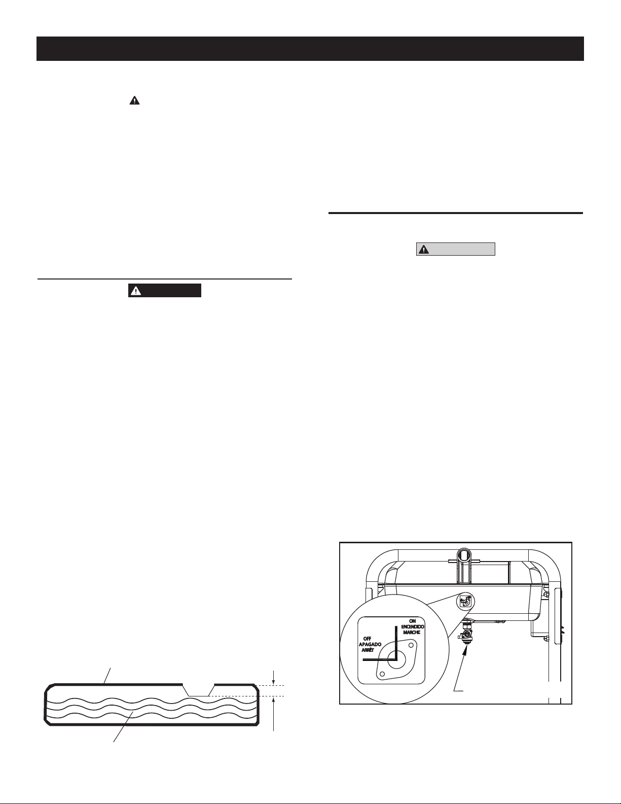
Operación
CUIDADO
Cualquier intento de arrancar el motor antes de
que se le haya dado servicio apropiado con el
n
aceite recomendado puede traer como resultado
una falla del motor.
Coloque el generador en una superficie nivelada.•
Limpie el área alrededor de la toma de aceite y retire la tapa de la toma •
y la varilla medidora.
Limpie la varilla.•
Llene lentamente el motor con aceite a través de la abertura hasta que •
llege a su marca de lleno. Deje de llenar ocasionalmente para revisar
el nivel de aceite. Tenga cuidado de no sobrecargarlo.
Instale la tapa del aceite y ajústela con seguridad.•
Después de esto, revise el nivel de aceite antes de arrancar cada vez.•
2.7.2 AGREGAR GASOLINA
PELIGRO
NUNCA llene el tanque de combustible en el
interior de la casa. Nunca llene el tanque de
gasolina mientras el motor está funcionando
o está caliente. Evite derramar gasolina
sobre un motor caliente. Deje enfriar al motor
completamente antes de llenar el tanque de
combustible. NO encienda cigarrillos o fume
cuando esté llenando el tanque de combustible.
No sobrecargue el tanque de combustible.
Deje siempre espacio para la expansión del
combustible. Si el tanque está muy lleno,
el combustible puede caer sobre el motor
caliente y causar un INCENDIO o EXPLOSIÓN.
Limpie cualquier derrame de combustible
inmediatamente.
No encienda cigarrillos ni fume cuando esté
llenando el tanque de combustible. La gasolina
es altamente INFLAMABLE y sus vapores son
EXPLOSIVOS.
Use gasolina sin plomo REGULAR para el motor del generador. No use •
ninguna gasolina con más de 10% de etanol adicional. No use gasolina
E85. No use aceite con gasolina.
Limpie el área alrededor de la tapa de llenado de combustible, •
sáquela.
Lentamente añada gasolina regular sin plomo al tanque de combustible. •
Llene hasta el fondo del filtro de pantalla. Tenga cuidado de no llenarlo
demasiado (figura 8).
Instale la tapa del combustible y limpie la gasolina que se haya •
derramado.
IMPORTANTE: Es importante evitar que se formen depósitos de goma en
las partes del sistema de combustible como el carburador, la manguera
de combustible o el tanque durante el almacenamiento. Los combustibles
mezclados con alcoholes (llamados gasohol, etanol o metanol) pueden
atraer la humedad, lo que llega a la separación y formación de ácidos
durante el almacenamiento. Los gases ácidos pueden dañar el sistema
de combustible de un motor durante el almacenamiento. Para evitar
problemas con el motor, el sistema de combustible deberá vaciarse antes
de almacenarse por 30 días o más. Ver la sección de “Almacenamiento”.
Nunca use productos limpiadores de motor o carburador en el tanque de
combustible ya que puede ocasionar daño permanente.
2.8 ARRANQUE DE MOTORES DE RECULE
ADVERTENCIA
Nunca arranque ni detenga el motor con
los dispositivos eléctricos conectados a los
receptáculos ni encendidos.
Desconecte todas las cargas eléctricas de los receptáculos de la •
unidad antes de arrancar el motor.
Asegúrese de que la unidad esté en una posición nivelada.•
ABRA• la válvula de cierre de combustible (figura 9).
Gire el interruptor RUN/STOP a la posición • ON.
Deslice la palanca de CHOKE del motor a la posición IZQUIERDA de •
“FULL CHOKE” (completo) (figura 10).
Para arrancar el motor, tome firmemente el manubrio del recule y •
tire lentemante hasta que se sienta que aumenta la resistencia. Tire
rápidamente hacia afuera.
Cuando el motor arranque, mueva la palanca de Choke a • 1/2 CHOKE
hasta que el motor funcione en forma suave y luego completamente
a la posición RUN. Si el motor arranca, mueva la palanca de Choke a
1/2 CHOKE hasta que el motor funcione en forma suave y luego a la
posición RUN.
NOTA:
Si el motor dispara, pero no sigue funcionando, mueva la palanca de
choke a FULL CHOKE y repita las instrucciones de arranque.
Figura 9 - Válvula de cierre de combustible
28
Figura 8 - Tanque de combustible
Tanque de combustible
Combustible
NO LLENAR más allá
de esta separación
CIERRE DE COMBUSTIBLE
Page 31

Mantenimiento
Figura 10 - Posición de Choke
PALANCA DE CHOKE
IZQUIERDA = CHOKE
DERECHA = FUNCIONAR
IMPORTANTE: No sobrecargue el generador. Asimismo, no sobrecargue
los receptáculos individuales. Estas tomas están protegidas contra
sobrecargas con interruptores de circuito tipo presionar para reiniciar.
Si la corriente nominal de cualquiera de los interruptores se excede, ese
interruptor se abre y la salida eléctrica a ese receptáculo se pierde. Lea
“No sobrecargue el generador” con mucho cuidado.
2.9 ARRANQUE DE MOTORES DE ARRANQUE ELÉCTRICO
NOTA:
Si el motor dispara, pero no sigue funcionando, mueva la palanca de
choke a FULL CHOKE y repita las instrucciones de arranque.
IMPORTANTE: No sobrecargue el generador. Asimismo, no sobrecargue
los receptáculos individuales. Estas tomas están protegidas contra
sobrecargas con interruptores de circuito tipo presionar para reiniciar.
Si la corriente nominal de cualquiera de los interruptores se excede, ese
interruptor se abre y la salida eléctrica a ese receptáculo se pierde. Lea
“No sobrecargue el generador” con mucho cuidado.
2.10 DETENER EL MOTOR
Apague todas las cargas, luego desconecte las cargas eléctricas de •
los receptáculos del panel del generador. Nunca arranque ni detenga el
motor con dispositivos eléctricos conectados y encendidos.
Deje que el motor funcione sin carga por algunos minutos para •
estabilizar las temperaturas internas del motor y del generador.
Mueva el interruptor de Run/Stop a la posición• OFF.
Cierre la válvula de combustible.•
2.11 SISTEMA DE APAGADO POR BAJO NIVEL DE ACEITE
El motor está equipado con un sensor de bajo nivel de aceite que apaga el
motor en forma automática cuando el nivel de aceite cae por debajo de un
nivel especificado. Si el motor se apaga y el tanque de combustible tiene
suficiente gasolina, revise el nivel de aceite de motor.
ADVERTENCIA
Nunca arranque ni detenga el motor con
los dispositivos eléctricos conectados a los
receptáculos ni encendidos.
Desconecte todas las cargas eléctricas de los receptáculos de la •
unidad antes de arrancar el motor.
Asegúrese de que la unidad esté en una posición nivelada.•
Abra la válvula de cierre del combustible (figura 9).•
Mueva la palanca de CHOKE del motor a la posición FULL CHOKE •
(completo) (figura 10).
Para arrancar el motor, mantenga presionado el interruptor de •
Start/Run/Stop en la posición “Start”. El motor intentará arrancar.
Cuando el motor arranque, suelte el interruptor a la posición “run”
(funcionamiento).
Cuando el motor arranque, mueva la palanca de Chole a “1/2 choke” •
hasta que el motor funcione en forma suave y luego completamente
a la posición “Run”. Si el motor decae, mueva la palanca de Chole
nuevamente a “1/2 choke” hasta que el motor funcione en forma
suave y luego a la posición “Run”.
Este generador también está equipado con un arrancador manual de •
recule que se puede usar si la batería está descargada.
NOTA:
El interruptor debe estar en posición RUN.
Para arrancar manualmente, tome firmemente el manubrio del recule •
y tire lentemante hasta que se sienta que aumenta la resistencia.
Tire rápidamente arriba para arrancar el motor. Luego siga la misma
secuencia de choke.
2.11.1 SENSANDO EL BAJO NIVEL DE ACEITE
Si el sistema detecta un bajo nivel de aceite durante la operación, el motor
se apaga. El motor no funcionará hasta que se haya llenado aceite de
nuevo a su nivel apropiado.
3.1 PROGRAMA DE MANTENIMIENTO
Siga los intervalos del calendario. Se requiere un servicio más frecuente
cuando se opera en condiciones adversas como las que se indica abajo.
Revise el nivel de aceite en cada uso
Cambie el aceite ‡ *Cada 100 horas o cambio de estación
Revise la claridad de la válvula ***Cada cambio de estación
Servicio del filtro de aire ** Cada 200 horas o cambio de estación
Reemplazo de bujías Cada cambio de estación
‡ Cambie el aceite luego de las primeras 30 horas de operación y luego en cada
cambio de estación.
* Cambie el aceite y el filtro de aceite cada mes si opera bajo condiciones
pesadas de carga o altas temperaturas.
** Limpie con más frecuencia bajo condiciones de operación que involucren polvo
y suciedad. Reemplace las partes del filtro de aire si no se les puede limpiar
adecuadamente.
*** Revise la claridad de la válvula y ajústela si es necesario luego de las
primeras 50 horas de operación y cada 100 horas luego de ello.
29
Page 32

Mantenimiento
3.2 ESPECIFICACIONES DEL PRODUCTO
3.2.1 ESPECIFICACIONES DEL GENERADOR
Capacidad eléctrica .....................................................5.0/5.5/6.5 kW**
Potencia de transitorio.................................................6.25/6.88/8.0 kW
Voltaje AC nominal ....................................................................120/240
Carga AC nominal
Corriente @ 240V (5.0/5.5/6.5 kW)................20.8/22.9/27.1 Amps**
Corriente @ 120V (5.0/5.5/6.5 kW)................41.6/45.8/54.2 Amps**
Frecuencia nominal ................................................ 60 Hz @ 3600 RPM
Fase .....................................................................................Monofásico
** Las potencias y corrientes máximas están sujetas a, y limitadas por, factores
tales como contenido en BTUs del combustible, altitud, condiciones del motor,
etc. La potencia máxima disminuye alrededor del 3.5% por cada 1000 pies
sobre el nivel del mar, y también disminuirá alrededor del 1% por cada 6ºC
(10ºF) por encima de los 16ºC (60ºF) de temperatura ambiente.
3.2.2 ESPECIFICACIONES DEL MOTOR
Desplazamiento.........................................................................................389 cc
Tipo de bujías .................................................. NHSP LDF7TC o Champion N9YC
Espaciamiento de la bujía ..................... 0.028-0.031 pulgadas o (0.70-0.80 mm)
Capacidad de gasolina ....................................................7.2 galones americanos
Tipo de aceite ......... Ver la cartilla en la sección “Antes de arrancar el generador”
Capacidad de aceite ......................................................................1 L (1.06 Qts.)
Tiempo de funcionamiento a 50% de carga (5.0/5.5/6.5 kW) .................10 horas
3.2.3 INFORMACIÓN DE EMISIONES
La agencia de protección ambiental (EPA) requiere que este generador
cumpla con los estándares de emisión en el escape. El motor usado en
este generador está certificado para cumplir los niveles de emisión de
EPA aplicables. Es importante seguir las especificaciones en la sección
de mantenimiento proporcionadas en este manual para asegurar que su
motor cumple con los estándares de emisión aplicables por la duración
de la vida del motor. El sistema de control de emisiones de este generador
consiste en lo siguiente:
Sistema de inducción de aire • Sistema de ignición•
~ Tubería/distribuidor de entrada ~ Bujía
~ Limpiador de aire ~ Bobina de arranque
Sistema de escape • Sistema de combustible•
~ Distribuidor de escape ~ Carburador
~ Silenciador
El período de cumplimiento de emisiones mencionado en la etiqueta de
cumplimiento de emisiones indica el número de horas de operación para
las que el motor ha demostrado cumplir los requerimientos de emisión
de la EPA.
3.3 RECOMENDACIONES GENERALES
La garantía del generador no cubre ítems que hayan sido objeto de abuso
o negligencia del operador. Para recibir el valor total de la garantía, el
operador debe hacer el mantenimiento del generador tal como se instruye
en este manual.
Se necesitará hacer algunos ajustes periódicamente para mantener
apropiadamente este generador.
Todos los ajustes en la sección de Mantenimiento de este manual
deberán hacerse al menos una vez en cada cambio de estación. Siga los
requerimientos del “Programa de mantenimiento”.
Una vez al año, reemplace las bujías y el filtro de aire. Bujías nuevas
y filtro de aire limpio aseguran una apropiada mezcla de airecombustible y ayudan a que el motor funcione mejor y dure más.
3.3.1 MANTENIMIENTO DEL GENERADOR
El mantenimiento del generador consiste en mantener a la unidad limpia y
seca. Opere y almacene la unidad en un ambiente limpio y seco donde no
esté expuesta a excesivo polvo, suciedad, humedad ni vapores corrosivos.
Las ranuras de aire de enfriamiento en el generador no deberán obstruirse
con nieve, hojas ni ningún material extraño.
Revise la limpieza del generador frecuentemente y límpielo cuando el
polvo, suciedad, humedad y otras sustancias extrañas sean visibles en
su superficie exterior.
Nunca inserte ningún objeto ni herramienta a
través de las ranuras de aire de refrigeración,
n
aún si el motor no está funcionando.
NO use una manguera de jardín para limpiar el generador.
El agua puede ingresar al sistema de combustible del motor
y causar problemas. Adicionalmente, si el agua ingresa al
generador a través de las ranuras de aire, algo del agua será
retenida en vacíos o grietas del aislamiento del bobinado del
rotor y estator. La acumulación del agua y el polvo en los
bobinados internos del generador eventualmente disminuirán
la resistencia de aislamiento de esos bobinados.
3.3.2 PARA LIMPIAR EL GENERADOR
Use un trapo húmedo para limpiar las superficies exteriores.•
Una escobilla suave de cerdas puede usarse para soltar suciedades •
pegadas, aceite, etc.
Se puede usar una aspiradora para levantar la suciedad suelta y •
restos.
Se puede usar una baja presión de aire (que no exceda las 25 psi) para •
soplar la suciedad. Inspeccione las ranuras de aire de ventilación y las
aberturas del generador. Estas aperturas deben mantenerse limpias y
sin obstrucciones.
NOTA:
CUIDADO
NOTA:
30
3.3.3 MANTENIMIENTO DEL MOTOR
PELIGRO
Cuando trabaje en el generador, siempre
desconecte el cable de la bujía y manténgalo
lejos de esta.
Page 33

Mantenimiento
3.3.4 REVISAR EL NIVEL DE ACEITE
Vea la sección “ANTES DE ARRANCAR EL GENERADOR” para mayor
información sobre la revisión del nivel de aceite. El nivel de aceite debe
revisarse antes de cada uso, o al menos cada ocho horas de operación.
Siempre mantenga el nivel de aceite.
3.3.5 CAMBIO DE ACEITE
Cambie el aceite cada 100 horas. Si está haciendo funcionar la unidad
en condiciones de polvo o suciedad, o en clima extremadamente cálido,
cambie el aceite con más frecuencia.
CUIDADO
El aceite caliente puede causar quemaduras.
Permita que el motor enfríe antes de drenar
n
el aceite. Evite una exposición prolongada o
repetida de la piel con el aceite usado. Lave
completamente las áreas expuestas con jabón.
Use las siguientes instrucciones para cambiar el aceite luego que el
motor enfríe:
Limpie el área alrededor de la manguera de drenaje del aceite.•
Retire la tapa de drenaje de aceite del motor y la tapa de llenado de •
aceite para que drene completamente en un contenedor adecuado.
Cuando el aceite haya drenado completamente, instale la tapa de •
drenaje de aceite y ciérrela con firmeza.
Llene el motor con el aceite recomendado. (Vea “Antes de arrancar el •
generador” para mayores recomendaciones sobre el aceite).
Limpie el aceite que se haya derramado.•
Disponga del aceite usado en un centro de recolección apropiado.•
3.4 SERVICIO DEL FILTRO DE AIRE
El motor no funcionará apropiadamente y puede dañarse si se usa un
filtro de aire sucio. Limpie el filtro de aire cada 200 horas o una vez al año
(figura 12). Límpielo o reemplácelo con mayor frecuencia si se opera en
condiciones de suciedad.
Retire la cubierta del filtro de aire.•
Lavar en agua jabonosa. Exprima el filtro para secarlo en una tela •
limpia (NO LO TUERZA).
Limpie la cubierta del filtro de aire antes de reinstalarlo.•
NOTA:
Para ordenar un filtro de aire nuevo, por favor póngase en contacto con
el centro de servicio autorizado más cercano al 1-888-436-3722.
Figura 12 - Filtro de aire
PASADOR
3.3.6 REEMPLAZO DE LA BUJÍA
Use bujía Champion N9YC o equivalente. Reemplace la bujía una vez al
año. Esto ayudará a que el motor arranque con mayor facilidad y funcione
mejor.
1. Detenga el motor y tire del cable de bujías colocándolo lejos de las
mismas.
2. Limpie el área alrededor de la bujía y retírela de la cabeza del
cilindro.
3. Coloque el espaciamiento de la bujía en 0.70-0.80 mm (0.028-0.031
in.). Instale la bujía con el espaciamiento correcto en la cabeza del
cilindro (figura 11).
Figura 11 - Espaciamiento de la bujía.
3.5 CLARIDAD DE LA VÁLVULA
Toma de entrada — 0.15 ± 0.02mm (frío), (0.006” ± 0.0008” pulg)•
Escape — 0.0020 ± 0.02mm (frío) (0.008” ± 0.0008” pulg)•
Luego de las primeras 50 horas de operación, revise la claridad de la
válvula en el motor y ajústela si es necesario.
Importante: Si se siente incómodo haciendo este procedimiento o no tiene
disponibles las herramientas apropiadas, por favor lleve el generador al
centro de servicio más cercano para ajustar la claridad de la válvula. Este
es un paso muy importante para asegurar la mayor vida de su motor.
31
Page 34

Mantenimiento
3.6 GENERAL
El generador deberá arrancarse al menos una vez cada siete días y
permitírsele funcionar al menos 30 minutos. Si esto no se puede hacer y
la unidad debe guardarse por más de 30 días, use la siguiente información
como guía para prepararlo para su almacenamiento.
PELIGRO
NUNCA almacene un motor con combustible
en el tanque en interiores o en áreas cerradas
poco ventiladas en donde los humos pueden
alcanzar una llama abierta, chispa o flama piloto
como en una chimenea, calentador de agua,
secadora de ropa u otros aparatos a gas.
Deje enfriar la unidad completamente antes de
almacenarse.
n
3.7 ALMACENAMIENTO POR LARGO PLAZO
Es importante evitar que se formen depósitos de goma en las partes
esenciales del sistema de combustible como el carburador, la manguera
de combustible o el tanque durante el almacenamiento. Asimismo,
la experiencia indica que los combustibles mezclados con alcoholes
(llamados gasohol, etanol o metanol) pueden atraer la humedad, lo que
llega a la separación y formación de ácidos durante el almacenamiento.
Los gases ácidos pueden dañar el sistema de combustible de un motor
durante el almacenamiento.
Para evitar problemas con el motor, el sistema de combustible deberá
vaciarse antes de almacenarse por 30 días o más, como sigue:
Retire toda la gasolina del tanque de combustible.•
PELIGRO
Drene el combustible en contenedores
apropiados en exteriores, lejos de las flamas
abiertas. Asegúrese de que el motor esté frío.
No fume.
Arranque y haga funcionar el motor hasta que se detenga por falta de •
combustible.
Mientras el motor esté aun caliente, drene el aceite del cárter. Rellene •
con el grado recomendado.
Retire la bujía y llene alrededor de 1/2 onza (15 ml) de aceite de motor •
en los cilindros. Cubra el agujero de la bujía con un trapo. Tire del
arrancador de recule un par de veces para lubricar los anillos del pistón
y el recorrido del cilindro.
CUIDADO
Evite la pulverización del agujero de la bujía en el
arranque.
Instale y ajuste la bujía. No conecte el cable de bujía.•
Limpie las otras superficies del generador. Revise que las aberturas •
y ranuras de aire de ventilación en el generador estén abiertas y sin
obstrucciones.
Almacene la unidad en un lugar limpio y seco.•
3.8 OTROS CONSEJOS PARA ALMACENAMIENTO
No almacene gasolina de una estación a otra.•
Reemplace la gasolina si empieza a oxidarse. El óxido o suciedad •
en la gasolina causará problemas con el carburador y el sistema de
combustible.
Si fuera posible, almacene la unidad en interiores y cúbrala para •
protegerla del polvo y la suciedad. ASEGÚRESE DE VACIAR EL
TANQUE DE COMBUSTIBLE.
Si no fuera práctico vaciar el tanque de combustible y la unidad tiene •
que almacenarse por un tiempo, use un estabilizador de combustible
comercial disponible y añádalo a la gasolina para prolongar la vida de
esta.
Cubra la unidad con una cubierta protectora adecuada que no retenga •
humedad.
PELIGRO
NUNCA cubra el generador mientras las áreas
del motor y el escape están calientes.
n
32
Page 35

Detección de fallas
Notas
4.1 GUÍA DE DETECCIÓN DE PROBLEMAS
PROBLEMA CAUSA CORRECCIÓN
El motor está funcionando, pero
no hay salida de AC disponible.
1. El interruptor de circuito está abierto.
2. Pobre conexión o cable defectuoso.
3. El dispositivo conectado está mal.
4. Falla en el generador.
1. Reinicie el interruptor de circuito.
2. Revise y repare.
3. Conecte otro dispositivo que esté en buenas condiciones.
4. Contacte a un servicio autorizado.
El motor funciona bien pero se
siente sobrecargado cuando las
cargas están conectadas.
El motor no arranca, o arranca
pero funciona en forma áspera.
El motor se apaga durante la
operación.
El motor pierde potencia. 1. La carga es demasiado alta.
1. Cortocircuito en la carga conectada.
2. El generador está sobrecargado.
3. La velocidad del motor es muy lenta.
4. Circuito del generador en corto.
1. El cierre de combustible está en OFF.
2. Filtro de aire sucio.
3. Falta gasolina.
4. Gasolina pasada.
5. El cable de la bujía no está conectado a esta.
6. Bujías en mal estado.
7. Agua en la gasolina.
8. Exceso de choke.
9. Nivel de aceite bajo
10. Mezcla de combustible demasiado rica.
11. Válvula de entrada atascada o cerrada.
12. El motor ha perdido compresión.
1. Falta gasolina.
2. Nivel de aceite bajo
3. Falla en el motor.
2. Filtro de aire sucio.
3. El motor necesita servicio.
1. Desconecte la carga eléctrica en corto.
2. Vea “No sobrecargue el generador”
3. Contacte a un servicio autorizado.
4. Contacte a un servicio autorizado.
1. Gire el cierre de combustible a ON.
2. Limpie o reemplace el filtro de aire.
3. Llene el tanque de combustible.
4. Drene y llene el tanque de combustible con gasolina fresca.
5. Conecte el cable a la bujía.
6. Reemplace la bujía.
7. Drene y llene el tanque de combustible con gasolina fresca.
8. Coloque la palanca de choke en posición No Choke.
9. Llene el cárter en el nivel apropiado.
10. Contacte a un servicio autorizado.
11. Contacte a un servicio autorizado.
12. Contacte a un servicio autorizado.
1. Llene el tanque de combustible.
2. Llene el cárter en el nivel apropiado.
3. Contacte a un servicio autorizado.
1. Reduzca la carga (Vea “No sobrecargue el generador”).
2. Limpie o reemplace el filtro de aire.
3. Contacte a un servicio autorizado.
El motor se pierde o
tartamudea.
1. El choke está abierto demasiado pronto
2. El carburador está funcionando muy rico o
muy ralo.
1. Mueva el choke a la posición media hasta que el motor
funcione suavemente.
2. Contacte a un servicio autorizado.
33
Page 36

Garantía
DECLARACIÓN DE GARANTÍA DE CONTROL DE EMISIONES
SUS DERECHOS Y OBLIGACIONES DE GARANTÍA
La Agencia de protección ambiental de los Estados Unidos (EPA) y Generac Power Systems, Inc. (Generac) se complacen en explicar
la garantía del sistema de control de emisiones para su nuevo equipo del año 2008 o posterior. Equipo nuevo que use motores
pequeños de chispa deben estar diseñados, construidos y equipados para cumplir estándares anti-smog muy exigentes para el gobierno
federal. Generac garantizará los sistemas de emisión en su motor por el periodo de tiempo listado abajo siempre que no haya abuso,
negligencia, modificación o mantenimiento inapropiado de su equipo.
Su sistema de control de emisión puede incluir partes como: carburador, sistema de ignición, sistema de combustible, convertidor
catalítico, y otros componentes asociados relacionados a la emisión (si los tuviera).
COBERTURA DE LA GARANTÍA DEL FABRICANTE:
Este sistema de control de emisión está garantizado por dos años. Si durante este periodo de garantía se encuentra que
cualquier parte relacionada a las emisiones está defectuosa en materiales o mano de obra, se efectuará las reparaciones o el
intercambio por parte de un concesionario de servicio autorizado de Generac.
RESPONSABILIDADES DE GARANTÍA DEL PROPIETARIO:
Como propietario del generador, usted es responsable de completar todos los mantenimientos requeridos tal como se lista en el
manual del propietario proporcionado por la fábrica. Para propósitos de garantía, Generac recomienda que usted conserve todos
los recibos que cubren el mantenimiento de su generador, pero Generac no puede rehusar la garantía sólo debido a la falta de
recibos.
Como propietario del generador, usted deberá ser consciente de que Generac puede negar cualquier y/o todas las coberturas y
responsabilidades de la garantía si su generador, o una parte o componente del mismo, ha fallado debido al abuso, negligencia,
mantenimiento inapropiado o modificaciones no aprobadas, o el uso de repuestos falsos o del mercado negro no fabricados,
suministrados o aprobados por Generac.
Usted es responsable de contactar a un concesionario autorizado de garantía de Generac tan pronto se presente el
problema. Las reparaciones de garantía deberán completarse en un tiempo razonable, sin exceder los 30 días.
El servicio de garantía puede arreglarse contactando ya sea a su concesionario de venta o a un concesionario de servicio de
garantía autorizado de Generac. Para ubicar al concesionario de servicio de garantía autorizado de Generac más cercano a usted,
llame a nuestro número gratuito.
1-800-333-1322
NOTA IMPORTANTE: Esta declaración de garantía explica sus derechos y obligaciones bajo la Garantía del sistema de control
de emisiones (ECS Warranty), que Generac le proporciona Generac siguiendo las leyes federales. También vea “Garantías
limitadas de Generac para los sistemas de potencia de Generac, Inc.” que se adjunta a este manual en una hoja separada,
también proporcionada a usted por Generac. Tenga en cuenta que esta garantía no se aplicará a ningún daño incidental,
consecuencial o indirecto causado por defectos en los materiales y mano de obra, o cualquier retraso en reparar o reemplazar las
partes defectuosas. Esta garantía reemplaza a todas las otras garantías, expresas o implícitas. ESPECÍFICAMENTE, GENERAC
NO OFRECE OTRAS GARANTÍAS COMO DE MERCANTIBILIDAD O ADECUACIÓN A UN USO PARTICULAR. Algunos estados
no permiten limitaciones en cuánto dura una garantía implícita, de modo que la limitación expresada arriba puede no aplicarse a
usted.
La garantía ECS se aplica sólo al sistema de control de emisiones de su nuevo equipo. Si hay algún conflicto en términos
entre la garantía ECS y la garantía de Generac, se aplicará la de Generac. Ambas garantías describen derechos y obligaciones
importantes respecto a su nuevo motor.
El servicio de garantía puede ser realizado sólo por un servicio de garantía autorizado de Generac. Cuando se requiera servicio
de garantía, se debe presentar evidencia que muestre la fecha de venta al comprador/propietario original.
Si usted tuviera alguna pregunta respecto a sus derechos y responsabilidades de garantía, deberá ponerse en contacto con
Generac en la siguiente dirección:
ATENCIÓN DEPARTAMENTO DE GARANTÍAS
GENERAC POWER SYSTEMS, INC.
P.O. BOX 297 • WHITEWATER, WI 53190
Parte 1
Parte No. 0H1911 Rev. A 01/09
34
Page 37

Garantía
GARANTÍA DEL SISTEMA DE CONTROL DE EMISIONES
Garantía de sistema de control de emisiones (garantía ECS) para equipo que usa motores pequeños de chispa.
(a) Aplicabilidad: Esta garantía se aplica a equipo que utiliza motores pequeños para fuera de pista. El periodo de garantía
ECS empezará en la fecha en que el equipo nuevo es comprado por o entregado a su propietario/comprador final original y
continuará por los siguientes 24 meses consecutivos.
(b) Cobertura general de la garantía de emisiones: Generac garantiza al propietario/comprador final original del motor o
equipamiento nuevo y a cada subsiguiente comprador/propietario que el ECS cuando se instaló estuvo:
(1) Diseñado, construido y equipado para cumplir con todas las regulaciones aplicables: y
(2) Libre de defectos en materiales y mano de obra que cause la falla de una parte garantizada en cualquier momento
durante el periodo de garantía ECS.
(c) La garantía sobre partes relacionadas a la emisión se interpretarán como sigue:
(1) Cualquier parte garantizada que no esté programada para reemplazo como mantenimiento requerido en el Manual del
propietario será garantizada en el periodo de garantía ECS. Si fallara cualquier parte durante el periodo de garantía ECS,
deberá ser reparado o reemplazado por Generac de acuerdo a la Subsección (4) más abajo. Cualquier parte así reparada
o reemplazada bajo la garantía ECS deberá ser garantizada por el resto del periodo de garantía ECS.
(2) Cualquier parte garantizada que esté programada sólo para inspección regular como se especifica en el Manual del
propietario será garantizada en el periodo de garantía ECS. Una declaración en el manual del propietario a efecto de
“reparar o reemplazar según sea necesario” no reducirá el periodo de garantía ECS. Cualquier parte así reparada o
reemplazada bajo la garantía ECS deberá ser garantizada por el resto del periodo de garantía ECS.
(3) Cualquier parte garantizada que esté programada para reemplazo según lo requiera el mantenimiento en el Manual del
Propietario deberá ser garantizado por el periodo de tiempo antes del primer punto de reemplazo programado para esa
parte. Si la parte falla antes del primer reemplazo programado, la parte será reparada o reemplazada por Generac de
acuerdo a la Subsección (4) más abajo. Cualquier parte relacionada a las emisiones así reparada o reemplazada bajo la
garantía ECS será garantizada por el resto del periodo antes del primer punto de reemplazo programado para aquella
parte.
(4) La reparación o reemplazo de cualquier parte garantizada relacionada a las emisiones bajo esta garantía ECS deberá
realizarse sin costo alguno para el propietario en un centro de servicio de garantía autorizado por Generac.
(5) No obstante las disposiciones de la subsección (4) arriba indicadas, los servicios o reparaciones por garantía deben ser
proporcionados en una instalación de servicio autorizada por Generac.
(6) Cuando el motor sea inspeccionado por un centro de servicio de garantía autorizado de Generac, el propietario/comprador
no será responsable de los costos de diagnóstico si la reparación se considera dentro de la garantía.
(7) A lo largo del periodo de garantía ECS, Generac mantendrá un suministro de partes garantizadas relacionadas a las
emisiones suficiente para cumplir la demanda esperada para tales repuestos.
(8) Cualquier repuesto relacionado a la emisión autorizado y aprobado por Generac puede usarse en la ejecución de
cualquier reparación o mantenimiento de garantía ECS y se proporcionará sin costo al comprador/propietario. Dicho uso
no reducirá las obligaciones de garantía ECS de Generac.
(9) Los repuestos no aprobados, añadidos, modificados, falsos y/o del mercado negro no se pueden usar para modificar
o reparar un motor Generac. Dicho uso invalida esta garantía ECS y será base suficiente para no aceptar un reclamo
por garantía ECS. Generac no podrá ser declarado responsable por fallas de cualquier parte garantizada de un equipo
Generac causadas por el uso de tales repuestos no aprobados, añadidos, modificados, falsos y/o del mercado negro.
LAS PARTES RELACIONADAS A LA EMISIÓN PUEDEN INCLUIR LO SIGUIENTE (SI SE
TIENE):
1) SISTEMA DE MEDICIÓN DE COMBUSTIBLE
A. CARBURADOR Y PARTES INTERNAS
B. REGULADOR DE PRESIÓN
2) SISTEMA DE INDUCCIÓN DE AIRE
A. DISTRIBUIDOR DE ENTRADA
B. FILTRO DE AIRE
3) SISTEMA DE IGNICIÓN
A. BUJÍAS
B. BOBINAS/MÓDULO DE IGNICIÓN
Parte 2
4) SISTEMA DE INYECCIÓN DE AIRE
A. VÁLVULA DE AIRE DE PULSO
5) SISTEMA DE ESCAPE
A. CATALIZADOR
B. REACTOR TÉRMICO
C. DISTRIBUIDOR DE ESCAPE
Parte No. 0H1911 Rev. A 01/09
35
Page 38

Garantía
GARANTÍA LIMITADA DE “DOS AÑOS” DE SISTEMAS DE POTENCIA GENERAC PARA
GENERADORES PORTÁTILES SERIE GP
Por un periodo de dos años desde la fecha de la venta original, Generac Power Systems, Inc. (Generac) garantiza sus generadores serie GP como libres de defectos en
materiales y mano de obra por los ítems y periodos indicados abajo. Generac, a su opción, reparará o reemplazará cualquier parte que, luego de un examen, inspección y
pruebas realizadas por un concesionario de servicio de garantía autorizado de Generac, se encuentre que está defectuoso. Cualquier equipo que el comprador/propietario
reclame como defectuoso debe ser regresado a y examinado por el concesionario de servicio de garantía autorizado por Generac más cercano. Todos los costos de transporte
bajo la garantía, incluyendo el retorno a la fábrica, serán por cuenta y prepagados por el propietario/comprador. Esta garantía se aplica sólo a los generadores portátiles serie
GP de Generac y no es transferible del propietario original. Guarde su comprobante de compra. Si usted no proporciona una prueba de la fecha de la compra inicial, se usará
la fecha de embarque del producto del fabricante para determinar el periodo de garantía.
PROGRAMACIÓN DE GARANTÍA
Las aplicaciones para consumidor están garantizadas por (2) años. Las aplicaciones comerciales y de alquiler están garantizadas por un (1) año o 1000 horas como máximo,
lo que llegue primero.
APLICACIÓN PARA CONSUMIDOR
AÑO UNO - 100% (cien por ciento) de cobertura en mano de obra y repuestos (se requiere comprobante de compra y mantenimiento):
• Todos los componentes
AÑO DOS- 100% (cien por ciento) de cobertura en repuestos (se requiere comprobante de compra y mantenimiento):
• Todos los componentes
APLICACIÓN COMERCIAL / DE ALQUILER
AÑO UNO – 100% (cien por ciento, O 1,000 horas, lo que ocurra primero) de cobertura en mano de obra y repuestos (se requiere comprobante de compra y mantenimiento):
• Todos los componentes
INTERNACIONAL
AÑO UNO (o 1000 horas, lo que ocurra primero) – Cobertura amplia limitada en mano de obra y partes listadas.
• TODOS LOS COMPONENTES
NOTA: Para el propósito de esta garantía “uso de consumidor” significa uso personal en casa residencial o recreacional por el comprador original. La garantía no aplica
a unidades usadas para Fuente Primaria de Energía en lugar del servicio público donde el servicio público se encuentre presente o donde el servicio público de
energía no exista normalmente. Una vez que el generador ha experimentado uso comercial o de alquiler, se le considerará en adelante un generador no para uso del
consumidor para propósitos de esta garantía.
Todos los gastos por garantía están sujetos a las condiciones definidas en el Manual de política de servicio de Generac.
ESTA GARANTÍA NO SE APLICARÁ A LO SIGUIENTE:
Generadores portátiles construidos por Generac antes de Junio de 2010.•
Generadores portátiles de Generac que utilizan repuestos que no son de Generac.•
Costos de mantenimiento normal y ajustes.•
Fallas causadas por combustibles o aceites contaminados, o la falta de niveles apropiados.•
Reparaciones o diagnósticos realizados por individuos diferentes a los concesionarios autorizados por Generac que no estén autorizados por escrito por Generac Power Systems.•
Fallas debido a, pero no limitándose a, el uso y desgaste normal, accidente, mal uso, abuso, negligencia o uso inapropiado. Como todo dispositivo mecánico, los motores Generac •
necesitan servicio y repuestos periódicamente para funcionar como están diseñados. Esta garantía no cubre reparaciones cuando el uso normal ha agotado la vida útil de una parte o
motor.
Las fallas causadas por cualquier causa externa o acto de Dios, como colisión, robo, vandalismo, disturbios o guerra, holocausto nuclear, incendio, congelamiento, electricidad atmos-•
férica, terremoto, tormentas, granizo, erupción volcánica, agua o inundaciones, tornados o huracanes.
El daño relacionado a roedores y/o plaga de insectos.•
Los productos que son modificados o alterados de manera no autorizada por Generac por escrito.•
Cualquier daño incidental, consecuencial o indirecto causado por defectos en los materiales y mano de obra, o cualquier retraso en reparar o reemplazar las partes defectuosas.•
Falla debido a una mala aplicación.•
Gastos de teléfono, teléfono celular, fax, acceso a internet u otros gastos de comunicación.•
Gastos relacionados a “instrucciones del cliente” o detección de problemas donde no se encuentre defecto de fábrica.•
Equipo de alquiler usado mientras se realiza las reparaciones de garantía.•
Flete de un día para otro o costos especiales de embarque para los repuestos.•
Sobretiempos, vacaciones o trabajo de emergencia.•
Baterías de arranque, fusibles, bombillos de luz y fluidos de motor.•
ESTA GARANTÍA REEMPLAZA A TODAS LAS OTRAS GARANTÍAS, EXPRESAS O IMPLÍCITAS. ESPECÍFICAMENTE, GENERAC NO OFRECE OTRAS GARANTÍAS COMO DE
MERCANTIBILIDAD O ADECUACIÓN A UN USO PARTICULAR. Cualquier garantía implícita permitida por ley, estará limitada en duración a los términos de la garantía expresa
dispuesta aquí. Algunos estados no permiten limitaciones en cuánto dura una garantía implícita, de modo que la limitación expresada arriba puede no aplicarse a usted. LA ÚNICA
RESPONSABILIDAD DE GENERAC SERÁ LA REPARACIÓN O REEMPLAZO DE LAS PARTES TAL COMO SE ESPECIFICA ARRIBA. EN NINGÚN CASO GENERAC SERÁ RESPONSABLE
POR CUALQUIER DAÑO INCIDENTAL O CONSECUENCIAL, AÚN SI TALES DAÑOS SEAN UN RESULTADO DIRECTO DE UNA NEGLIGENCIA DE GENERAC. Algunos estados no permiten la
exclusión o limitación de daños accidentales o resultantes, de modo que la limitación mencionadas más arriba podrían no aplicarse a usted. Esta garantía le da a usted derechos legales
específicos. Usted también tiene otros derechos dependiendo del Estado.
GENERAC POWER SYSTEMS, INC.
P.O. BOX 8 • Waukesha, WI 53187
Tel: (888) GENERAC (436-3722) • Fax: (262) 544-4851
Para ubicar al concesionario autorizado más cercano visite nuestro sitio web: www.generac.com
Parte No. 0H8902 Revisión A (05/19/10)
Manual Parte No. 0H9059 Rev. C (08/02/10) Impreso en China.
Page 39

MODÈLES : 005938-0, 005939-0,
GARANTIE
LIMITÉE DE
2 ANS2 ANS
005940-0, 005941-0
Manuel d'entretien
Générateur portable série GP
www.generac.com ou 1-888-436-3722
37
Page 40

Table des matières
Introduction ........................................................... 39
Lire attentivement ce manuel ............................... 39
Règles de sécurité ................................................ 39
Index des normes.........................................................41
Informations générales ......................................... 41
1.1 Déballage .....................................................................41
1.1.1 Boîte d'accessoires ..........................................41
1.2 Montage .......................................................................41
1.2.1 Montage du kit d'accessoires ...........................41
1.2.2 Branchement du démarreur
(démarrage électrique uniquement) ..................41
Fonctionnement .................................................... 41
2.1 Bien connaître le générateur .........................................41
2.2 Horomètre ....................................................................42
2.3 Cordons et connecteurs ...............................................44
2.3.1 Prise double, 120 V c.a., 20 A .........................44
2.3.2 Prise 120/240 V c.a., 30 A ..............................44
2.4 Utilisation du générateur ...............................................44
2.4.1 Mise à la terre du générateur............................44
2.4.2 Branchement des charges électriques ..............44
2.5 Ne pas surcharger le générateur ...................................45
2.6 Guide de référence de wattage .....................................45
2.7 Avant le démarrage du générateur ................................45
2.7.1 Ajout de l'huile de moteur .................................45
2.7.2 Ajout de l'essence ............................................46
2.8 Démarrage des moteurs à démarrage manuel...............46
2.9 Démarrage des moteurs à démarrage électrique ...........47
2.10 Arrêt du moteur ............................................................47
2.11 Système d'arrêt de bas niveau d'huile ...........................47
2.11.1 Détection de bas niveau d'huile ........................47
Maintenance ......................................................... 41
3.1 Programme de maintenance .........................................41
3.2 Caractéristiques techniques des produits ......................48
3.2.1 Caractéristiques techniques du générateur .......48
3.2.2 Caractéristiques techniques du moteur .............48
3.2.3 Informations relatives aux émissions ................48
3.3 Recommandations générales ........................................48
3.3.1 Maintenance du générateur ..............................48
3.3.2 Nettoyage du générateur ..................................48
3.3.3 Maintenance du moteur ...................................48
3.3.4 Vérification du niveau d'huile ............................49
3.3.5 Changement de l'huile ......................................49
3.3.6 Remplacement des bougies d'allumage ............49
3.4 Entretien du filtre à air ..................................................49
3.5 Jeu des soupapes ........................................................49
3.6 Généralités ...................................................................50
3.7 Stockage à long terme .................................................50
3.8 Autres conseils de stockage .........................................50
Dépannage .......................................................... 51
4.1 Guide de dépannage .....................................................51
Garantie ...............................................................52
38
Page 41

Introduction
INTRODUCTION
Nous vous remercions d'avoir acheté ce modèle fabriqué par Generac
Power Systems, Inc. Ce modèle est un générateur entraîné par moteur
compact, à haute performance, refroidi à l'air, conçu pour fournir
l'alimentation électrique afin de faire fonctionner les charges électriques
lorsqu'aucun réseau électrique n'est disponible ou à la place du réseau en
raison d'une coupure de courant.
LIRE ATTENTIVEMENT CE MANUEL
En cas d'incompréhension d'une partie de ce manuel, contacter le
dépositaire agréé le plus proche pour connaître les procédures de
démarrage, de fonctionnement et d'entretien.
L'opérateur est responsable de l'utilisation correcte et sûre de l'équipement.
Nous recommandons fortement à l'opérateur de lire ce manuel et
de comprendre complètement toutes les instructions avant d'utiliser
l'équipement. Nous recommandons également fortement d'apprendre à
d'autres utilisateurs comment correctement démarrer et faire fonctionner
l'unité. Cela les prépare au cas où ils auraient besoin de faire fonctionner
l'équipement pour une urgence.
Le générateur peut fonctionner en toute sécurité, de façon efficace et de
façon fiable uniquement s'il est correctement installé, utilisé et entretenu.
Avant de faire fonctionner ou d'effectuer l'entretien du générateur :
Se familiariser avec et respecter strictement tous les codes et •
réglementations locaux, d'État et nationaux.
Lire attentivement tous les avertissements de sécurité figurant dans ce •
manuel et sur le produit.
Se familiariser avec ce manuel et l'unité avant de l'utiliser.•
Le fabricant ne peut pas anticiper toutes les situations possibles qui
peuvent impliquer un danger. Les avertissements de ce manuel et figurant
sur les étiquettes et les autocollants apposés sur l'unité ne sont, toutefois,
pas exhaustifs. Si vous suivez une procédure, une méthode de travail ou
une technique de fonctionnement que le fabricant ne recommande pas en
particulier, assurez-vous qu'elle est sans danger pour les autres. S'assurer
que la procédure, la méthode de travail ou la technique de fonctionnement
choisie ne rende pas le générateur dangereux.
LES INFORMATIONS CONTENUES DANS LE PRÉSENT MANUEL SE
BASENT SUR LES MACHINES EN PRODUCTION AU MOMENT DE LA
PUBLICATION. GENERAC SE RÉSERVE LE DROIT DE MODIFIER CE
MANUEL À TOUT MOMENT.
RÈGLES DE SÉCURITÉ
Dans tout ce manuel, et sur les étiquettes et sur les autocollants apposés
sur le générateur, les blocs DANGER, AVERTISSEMENT, ATTENTION et
REMARQUE servent à alerter le personnel d'instructions spéciales au sujet
d'une opération spécifique qui peut s'avérer dangereuse si elle n'est pas
effectuée correctement ou avec précaution. Les respecter attentivement.
Leurs définitions sont les suivantes :
INDIQUE UNE SITUATION OU UNE ACTION DANGEREUSE QUI, SI ELLE
N'EST PAS ÉVITÉE, ENTRAÎNERA LA MORT OU DES BLESSURES GRAVES.
AVERTISSEMENT !
Indique une situation ou une action dangereuse qui, si elle n'est pas
évitée, pourrait entraîner la mort ou des blessures graves.
ATTENTION !
Indique une situation ou une action dangereuse qui, si elle n'est pas
évitée, entraînera des blessures légères ou modérées.
REMARQUE :
Les remarques contiennent des informations supplémentaires
importantes relatives à une procédure et se trouvent dans le corps de
texte régulier de ce manuel.
Ces avertissements de sécurité ne peuvent pas éliminer les dangers qu'ils
signalent. Le sens commun et le respect strict des instructions spéciales
lors de l'action ou l'entretien sont essentiels pour éviter les accidents.
Quatre symboles de sécurité couramment utilisés accompagnent les
blocs DANGER, AVERTISSEMENT et ATTENTION. Chacun indique le type
d'informations suivant :
Ce symbole indique des informations importantes
relatives à la sécurité qui, si elles ne sont pas
n
suivies, pourraient mettre en danger la sécurité
personnelle et/ou les biens.
Ce symbole indique un risque potentiel d'explosion.
Ce symbole indique un risque potentiel d'incendie.
Ce symbole indique un risque potentiel
d'électrocution.
DANGERS GÉNÉRAUX
Ne jamais faire fonctionner dans un espace clos ou à l'intérieur. •
Pour des raisons de sécurité, le fabricant recommande que la •
maintenance de cet équipement soit effectuée par un dépositaire
agréé. Inspecter régulièrement le générateur et contacter le dépositaire
agréé le plus proche pour les pièces qui nécessitent une réparation ou
un remplacement.
Faire fonctionner le générateur uniquement sur des surfaces de niveau •
et où il ne sera pas exposé à l'humidité, aux saletés, à la poussière ou
aux vapeurs corrosives excessives.
Tenir les mains, les pieds, les vêtements, etc., à distance des courroies •
de transmission, des ventilateurs et d'autres pièces mobiles. Ne jamais
retirer tout protège-ventilateur pendant que l'unité fonctionne.
Certaines pièces du générateur deviennent extrêmement chaudes •
pendant le fonctionnement. Rester à distance du générateur tant qu'il
n'a pas refroidi afin d'éviter des brûlures graves.
NE PAS faire fonctionner le générateur sous la pluie.•
Ne pas modifier la construction du générateur ni les commandes, ce •
qui pourrait créer une condition de fonctionnement dangereuse.
Ne jamais démarrer ou arrêter l'unité avec les charges électriques •
branchées aux prises ET avec des dispositifs branchés sous tension.
Démarrer le moteur et le laisser se stabiliser avant de brancher les
charges électriques. Débrancher toutes les charges électriques avant
d'arrêter le générateur.
Ne pas insérer d'objet dans les fentes de refroidissement de l'unité.•
Lors du travail sur cet équipement, conserver l'alerte à tout moment. •
Ne jamais travailler sur l'équipement en cas de fatigue physique ou
mentale.
Ne jamais utiliser le générateur ou n'importe laquelle de ses pièces •
comme marche. Monter sur l'unité peut écraser et casser les pièces,
et peut entraîner des conditions de fonctionnement dangereuses suite
à une fuite de gaz d'échappement, une fuite de carburant, une fuite
d'huile, etc.
39
Page 42
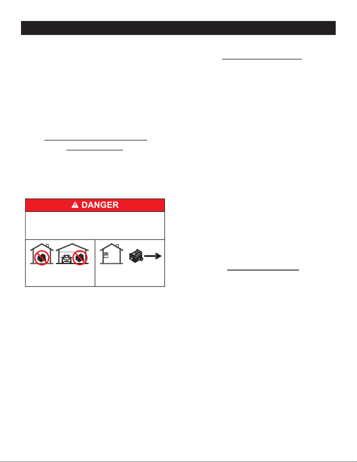
Règles de sécurité
Sur les modèles à démarrage électrique, débrancher le câble de •
batterie POSITIF (+) du démarreur du moteur OU le câble de batterie
NÉGATIF (-) de la borne de la batterie, ce qui est le plus facile, avant
de transporter le générateur.
REMARQUE :
Ce générateur est équipé d'un silencieux pare-étincelles. Le
propriétaire / l'opérateur du générateur devra garder le pareétincelles en bon état. Dans l'État de Californie, un pare-étincelles
est exigé par la loi (Section 4442 du California Public Resources
Code (Code de ressources publiques de Californie)). Les autres États
peuvent avoir des lois similaires. Les lois fédérales s'appliquent sur
les terres fédérales.
DANGERS D'ÉCHAPPEMENT ET
D'EMPLACEMENT
Ne jamais faire fonctionner dans un espace clos ou à l'intérieur. •
NE JAMAIS utiliser à l'intérieur ou dans des espaces partiellement
clos tels que les garages, même si les portes et les fenêtres sont
ouvertes ! Utiliser UNIQUEMENT à l'extérieur et loin des fenêtres,
portes ouvertes, ventilations, et dans un espace dans lequel le gaz
d'échappement ne s'accumulera pas de façon mortelle.
Utiliser un générateur à l'intérieur PEUT VOUS
TUER EN QUELQUES MINUTES.
Les gaz d'échappement du générateur contiennent du monoxyde
de carbone. C'est un gaz toxique invisible et inodore.
DANGERS ÉLECTRIQUES
Le générateur produit une tension dangereusement haute pendant •
sonfonctionnement. Éviter le contact avec les fils nus, les bornes, les
branchements, etc., pendant le fonctionnement de l'unité, même sur
l'équipement branché au générateur. S'assurer que tous les couvercles,
les dispositifs de protection et les barrières sont en place avant de faire
fonctionner le générateur.
Ne jamais manipuler tout type de cordon ou de dispositif électrique •
qui est dans l'eau, alors que vous êtes pieds nus ou que vos
mains ou vos pieds sont mouillés. CELA ENTRAÎNERA UN RISQUE
D'ÉLECTROCUTION.
Le National Electric Code (Code électrique national) exige que le •
bâti et que les pièces externes électriquement conductrices du
générateur soient correctement reliés à une terre approuvée. Les
codes électriques locaux peuvent également exiger la bonne mise à
la terre du générateur. Consulter un électricien local pour connaître les
exigences de mise à la terre dans la région.
Utiliser un disjoncteur de fuite à la terre dans toute zone humide ou très •
conductrice (telle que le carter protecteur métallique ou l'aciérie).
Ne pas utiliser de cordons électriques usés, nus, effilochés ou •
autrement endommagés avec le générateur.
Avant d'effectuer toute maintenance sur le générateur, débrancher la •
batterie de démarrage du moteur (le cas échéant) afin d'empêcher un
démarrage accidentel. Débrancher le câble de la borne de la batterie
signalée par l'inscription NEGATIVE (Négatif), NEG ou le signe (–) en
premier. Rebrancher ce câble en dernier.
En cas d'accident causé par électrocution, couper immédiatement la •
source d'alimentation électrique. Si cela est impossible, essayer de
libérer la victime du conducteur sous tension. ÉVITER TOUT CONTACT
DIRECT AVEC LA VICTIME. Utiliser un objet non conducteur, comme
une corde ou une planche, pour libérer la victime du conducteur sous
tension. Si la victime est inconsciente, assurer les premiers secours
et demander une aide médicale immédiate.
NE JAMAIS utiliser à l'intérieur
d'une maison ou d'un garage,
MÊME SI les portes et les
fenêtres sont ouvertes.
Les fumées d'échappement du moteur contiennent du monoxyde de •
carbone, un gaz toxique invisible et inodore. Ce gaz toxique, s'il est
respiré en concentrations suffisantes, peut entraîner une perte de
conscience ou même la mort.
Un débit approprié, non obstrué d'air de refroidissement et de ventilation •
est important pour corriger le fonctionnement du générateur. Ne pas
modifier l'installation ou ne pas laisser même un blocage partiel de
l'alimentation de ventilation, étant donné que cela peut sérieusement
affecter le fonctionnement sûr du générateur. Il FAUT faire fonctionner
le générateur à l'extérieur.
Ce système d'échappement doit être correctement entretenu. Ne rien •
faire qui pourrait rendre le système d'échappement dangereux ou non
conforme aux codes locaux et/ou normes locales.
Toujours utiliser un détecteur d'oxyde de carbone à alimentation par •
batterie à l'intérieur, conformément aux instructions du fabricant.
Si vous commencez à vous sentir malade, à avoir des étourdissements •
ou à vous sentir faible après le fonctionnement du générateur, respirez
de l'air frais IMMÉDIATEMENT. Consultez un médecin car vous pourriez
avoir été empoisonné au monoxyde de carbone.
Utiliser UNIQUEMENT à
l'EXTÉRIEUR et loin des
fenêtres, portes et
ventilations.
RISQUES D'INCENDIE
L'essence est extrêmement INFLAMMABLE et ses vapeurs sont •
EXPLOSIVES. Ne pas produire de fumée, flammes nues, étincelles
ou chaleur à proximité de l'endroit où l'essence est manipulée.
Ne jamais ajouter de carburant lorsque l'unité fonctionne ou est chaude. •
Laisser le moteur complètement refroidir avant d'ajouter du carburant.
Ne jamais remplir le réservoir d'essence à l'intérieur. • Respecter
toutes les lois réglementant le stockage et la manipulation de
l'essence.
Ne pas trop remplir le réservoir d'essence. Toujours laisser de la •
place pour l'expansion du carburant. En cas de suremplissage du
réservoir, le carburant peut déborder sur un moteur chaud et entraîner
un INCENDIE ou une EXPLOSION. Ne jamais stocker le générateur avec
le réservoir rempli de carburant étant donné que les vapeurs d'essence
pourraient atteindre une flamme ouverte, des étincelles ou une
veilleuse (comme il y en a sur une chaudière, un chauffe-eau ou sur
un sèche-linge). Cela peut entraîner un INCENDIE ou une EXPLOSION.
Laisser l'unité complètement refroidir avant le stockage.
Nettoyer immédiatement toute éclaboussure de carburant ou d'huile. •
S'assurer qu'aucune matière combustible ne reste sur ou à proximité
du générateur. Garder l'espace environnant du générateur propre et
sans débris et garder un jeu de cinq (5) pieds sur tous les côtés afin
de permettre une aération adaptée du générateur.
40
Page 43

Ne pas insérer d'objet dans les fentes de refroidissement de l'unité.•
Ne pas• faire fonctionner le générateur si des dispositifs électriques
branchés surchauffent ; si la puissance électrique est perdue ; si le
moteur ou le générateur fait des étincelles ; si des flammes ou de la
fumée sont détectées alors que l'unité fonctionne.
Garder un extincteur à proximité du générateur à tout moment. •
INDEX DES NORMES
En l'absence de normes, codes, réglementations et lois applicables, les
informations publiées indiquées ci-dessous peuvent servir de directive
pour le fonctionnement de cet équipement. Toujours se reporter à la
dernière révision disponible pour les normes indiquées.
1. NFPA N° 70, NFPA HANDBOOK OF NATIONAL ELECTRIC CODE
(Manuel NFPA du code électrique national).
2. Article X, NATIONAL BUILDING CODE (Code de construction national),
disponible auprès de l'American Insurance Association, 85 John
Street, New York, N.Y. 10038.
3. AGRICULTURAL WIRING HANDBOOK (Manuel de câblage agricole),
disponible auprès du Food and Energy Council, 909 University
Avenue, Columbia, MO 65201.
4. ASAE EP-3634, INSTALLATION AND MAINTENANCE OF FARM
STANDBY ELECTRICAL SYSTEMS (Installation et maintenance des
systèmes électriques de secours pour les fermes), disponible auprès
de l'American Society of Agricultural Engineers, 2950 Niles Road, St.
Joseph, MI 49085.
Règles de sécurité
N° DE MODÈLE :
N° DE SÉRIE :
Emplacement ID de l'unité
MODÈLE D'ÉTIQUETTE
AVERTISSEMENT PROPOSITION 65 CALIFORNIE
L'échappement du moteur et certains de ses constituants sont
susceptibles selon l'État de Californie d'entraîner des cancers,
des malformations congénitales ou pouvant être nocifs pour le
système reproductif.
AVERTISSEMENT PROPOSITION 65 CALIFORNIE
Ce produit contient ou émet des produits chimiques susceptibles
selon l'État de Californie d'entraîner des cancers, des
malformations congénitales ou autres maladies pouvant être
nocives pour le système reproductif.
41
Page 44

Informations générales
1.1 DÉBALLAGE
Retirer tous les éléments d'emballage.•
Enlever la boîte d'accessoires séparée.•
Retirer le générateur du carton.•
1.1.1 BOÎTE D'ACCESSOIRES
Vérifier le contenu de la boîte. Si des pièces sont absentes ou endommagées,
merci de localiser un dépositaire agréé au 1-888-436-3722.
1 - Manuel d'entretien • 1 - Poignée•
1 - Litre d'huile SAE 30 • 1 - Pied du bâti•
2 - Roues jamais plates • 1 - Chargeur de batterie (démarrage •
électrique uniquement)
1 - Sac de matériel (contenant ce qui suit) :•
• 2 - Pieds en caoutchouc • 2 - Boulons M8 (longs)
• 2 - Axes d'essieu de 0,5 po. • 2 - Boulons M8 (courts)
• 2 - Goupilles fendues • 2 - Écrous borgnes M8
• 2 - Rondelles plates de 0,5 po. • 4 - Écrous à collet hexagonal M8
1.2 MONTAGE
Il est nécessaire d'effectuer quelques étapes de montage avant d'utiliser
le générateur. Si des problèmes se présentent lors du montage du
générateur, merci d'appeler la ligne d'assistance pour les générateurs
au 1-888-77LOWES.
1.2.1 MONTAGE DU KIT D'ACCESSOIRES
Les roues sont conçues dans l'unité pour améliorer considérablement la
portabilité du générateur.
Vous aurez besoin des outils suivants pour correctement installer le kit :
Pinces à bec effilé•
Cliquet et une douille de 13 mm (0,5 po.) •
Clé polygonale de 13 mm (0,5 po.)•
REMARQUE :
Les roues ne sont pas conçues pour une utilisation sur la route.
1. Se reporter au Schéma 1 et installer les roues comme suit :
• Faire glisser les axes d'essieu à travers la roue, la rondelle plate de
0,5 po. et le support de la roue sur le bâti.
• Insérer la goupille fendue à travers l'axe d'essieu, puis plier les
languettes (des goupilles fendues) vers l'extérieur afin de les fixer.
2. Se reporter au Schéma 1 et installer le pied du bâti et les butoirs en
caoutchouc comme indiqué.
• Faire glisser les axes des butoirs en caoutchouc à travers le pied
du bâti, puis installer les écrous à collet de blocage.
• Faire glisser les boulons à tête hexagonale à travers les rondelles
plates à travers les trous dans le longeron de cadre de châssis.
• Faire glisser le pied du bâti sur les boulons à tête hexagonale, puis
installer les écrous à collet de blocage.
3. Se reporter au Schéma 1 et installer la poignée comme indiqué.
• Faire glisser les boulons longs à travers le support de poignée et la
poignée, puis installer les écrous hexagonaux.
Schéma 1 – Roue et poignée
BOULON M8 (LONG)
ÉCROU BORGNE M8
2 X BOULON M8 (COURT)
POIGNÉE
2 X ROUE
PIED DU BÂTI
2 X PIED EN CAOUTCHOUC
4 X ÉCROU M8
2 X AXE D'ESSIEU
2 X RONDELLE PLATE DE 0,5 PO.
2 X GOUPILLE FENDUE
1.2.2 BRANCHEMENT DU DÉMARREUR (DÉMARRAGE
ÉLECTRIQUE UNIQUEMENT)
L'unité a été envoyée avec le câble de démarreur débranché.
Pour brancher le démarreur :
1. Localiser le câble de démarreur.
2. Rabattre la protection en vinyle sur le câble de démarreur.
3. Retirer l'écrou et la rondelle du montant du démarreur.
4. Placer le câble de démarreur sur le montant et remettre la rondelle et
l'écrou.
2.1 BIEN CONNAÎTRE LE GÉNÉRATEUR
Merci de lire le Manuel d'entretien et les Règles de sécurité avant de
faire fonctionner ce générateur.
Comparer le générateur aux Schémas 2 à 4 pour vous familiariser avec
les emplacements des divers contrôles et réglages. Conserver ce manuel
pour mémoire.
1. Prise double à DDFT 120 V c.a., 20 A – Fournit une alimentation
électrique pour le fonctionnement d'un éclairage électrique,
d'appareils, d'outils et de charges de moteur 120 V c.a., 20 A,
monophasé, 60 Hz.
2. Prise à verrouillage 120/240 V c.a., 30 A – Fournit une alimentation
électrique pour le fonctionnement d'un éclairage électrique,
d'appareils, d'outils et de charges de moteur 120 V et / ou 240 V
c.a., 30 A, monophasé, 60 Hz.
3. Disjoncteurs (c.a.) – Chaque prise est fournie avec un disjoncteur
de type « pousser pour réenclencher » pour protéger le générateur
contre les surcharges électriques.
4. Vidange d'huile – Utilisé pour vidanger l'huile de moteur.
5. Filtre à air – Filtre l'air aspiré par le moteur.
6. Étrangleur – Utilisé au démarrage d'un moteur froid.
7. Réservoir d'essence – Voir les Caractéristiques techniques du
générateur pour la contenance du réservoir.
8. Borne de mise à la terre – Relie le générateur à une terre
approuvée. Voir la section « Mise à la terre du générateur » pour plus
d'informations.
9. Interrupteur Run/Stop (Marche/Arrêt) – Contrôle le fonctionnement
du générateur (modèles à démarrage manuel uniquement).
9A. Interrupteur de démarrage – Utilisé pour démarrer le moteur à
partir du démarreur du moteur (modèles à démarrage électrique
uniquement).
10. Pot d'échappement – Rend silencieux le moteur.
42
Page 45

Fonctionnement
Schéma 2 - Panneau de commande
11. Poignée – Pivoter et rétracter pour le stockage. Appuyer sur le
bouton à ressort pour déplacer les poignées.
12. Chapeau de gaz assis – Emplacement de remplissage d'huile.
13. Jauge de carburant – Indique le niveau de carburant dans le
réservoir.
14. Remplissage d'huile – Ajouter de l'huile ici.
15. Lanceur à rappel – Utiliser pour démarrer le moteur manuellement.
16. Soupape d'arrêt – Soupape entre le réservoir d'essence et le
carburateur.
17. Entrée du chargeur de batterie – Cette prise a la capacité de
recharger la batterie rechargeable c.c. de 12 volts, équipée d'un
chargeur d'adaptateur de 12 volts qui est inclus dans la boîte
d'accessoires. Derrière l'entrée du chargeur de la batterie, il y a
un fusible en ligne de 1,50 A qui se trouve à l'intérieur du panneau
de commande afin de protéger la batterie (démarrage électrique
uniquement).
18. Batterie – Met sous tension le démarreur électrique (démarrage
électrique uniquement).
19. Horomètre – Relève les heures de fonctionnement.
Schéma 3 - Commandes du générateur
Schéma 4 - Commandes du générateur
2.2 HOROMÈTRE
L'horomètre relève les heures de fonctionnement pour la maintenance
programmée :
Un message « CHG OIL » s'affichera toutes les 100 heures. Le message
clignotera une heure avant et une heure après chaque intervalle de 100
heures, laissant une marge de deux heures pour effectuer l'entretien.
Ce message commencera à clignoter à la 99ème heure et se désactivera
à la 101ème heure, laissant une marge de deux heures pour effectuer
l'entretien.
Toutes les 200 heures, l'icône « SVC » située en bas à gauche de l'écran
clignotera. Le message clignotera une heure avant et une heure après
chaque intervalle de 200 heures, laissant une marge de deux heures pour
effectuer l'entretien.
Lorsque l'horomètre est en mode Flash Alert (Alerte clignotante), le
message de maintenance s'affichera toujours en alternance avec le
temps écoulé en heures et en dixièmes. Les heures feront clignoter quatre
heures, puis s'afficheront en alternance avec le message de maintenance
quatre fois jusqu'à ce que la réinitialisation de l'horomètre.
100 heures - CHG OIL — Intervalle de changement d'huile (Toutes les •
100 heures)
43
Page 46

Fonctionnement
2.3 CORDONS ET CONNECTEURS
2.3.1 PRISE DOUBLE, 120 V C.A., 20 A
Il s'agit d'une prise de 120 volts protégée contre la surcharge par un
disjoncteur de type « pousser pour réenclencher » de 20 A (Schéma 5).
Utiliser chaque prise pour alimenter les charges électriques monophasées
de 120 V c.a., 60 Hz nécessitant 2 400 watts (2,4 kW) ou 20 A de
courant. Utiliser uniquement des cordons à trois fils avec mise à la terre,
bien isolés, de haute qualité conçus pour 125 Volts à 20 A (ou plus).
Garder les cordons prolongateurs aussi courts que possible, de préférence
à une longueur inférieure à 15 pieds, afin d'empêcher une chute de tension
et une surchauffe potentielle des câbles.
Schéma 5 - Prise double, 120 V c.a., 20 A
2.4 UTILISATION DU GÉNÉRATEUR
Si des problèmes se présentent lors du fonctionnement du générateur, merci
d'appeler la ligne d'assistance pour les générateurs au 1-888-436-3722.
2.4.1 MISE À LA TERRE DU GÉNÉRATEUR
Le National Electrical Code (Code électrique national) exige que le bâti
et que les pièces externes électriquement conductrices de ce générateur
soient correctement reliées à une terre approuvée (Schéma 7). Les
codes électriques locaux peuvent également exiger la bonne mise à la
terre de l'unité. À cette fin, brancher un fil toronné en cuivre de 10 AWG
(calibre américain des fils) à la borne de mise à la terre et à une tige en
cuivre conduite à la terre ou une tige à la terre (électrode) en laiton fournit
une protection appropriée contre les électrocutions. Cependant, les codes
locaux peuvent fortement varier. Consulter un électricien local pour
connaître les exigences de mise à la terre dans la région.
Schéma 7 - Mise à la terre du générateur
2.3.2 PRISE 120/240 V C.A., 30 A
Utiliser une fiche NEMA L14-30 avec cette prise (tourner pour verrouiller/
déverrouiller). Brancher un cordon à 4 fils avec mise à la terre adapté à la
prise et à la charge souhaitée. Le cordon doit être conçu pour 250 V c.a.
à 30 A (ou plus) (Schéma 6).
Schéma 6 - Prise 120/240 V c.a., 30 A
Utiliser cette prise pour faire fonctionner les charges monophasées de
120 V c.a., 60 Hz nécessitant 3 600 watts (3,6 kW) d'alimentation à
30 A ou des charges monophasées de 240 V c.a., 60 Hz nécessitant
7 200 watts (7,2 kW) d'alimentation à 30 A. La prise est protégée par deux
disjoncteurs de type « pousser pour réenclencher » de 25 A (5/ 5,5 kW)
ou deux disjoncteurs de 30 A (6,5 kW).
La bonne mise à la terre du générateur aidera à empêcher une
électrocution en cas de condition de défaut de mise à la terre dans le
générateur ou dans les dispositifs électriques branchés. La bonne mise
à la terre aide également à dissiper l'électricité statique, qui s'accumule
souvent dans les dispositifs non mis à la terre.
2.4.2 BRANCHEMENT DES CHARGES ÉLECTRIQUES
NE PAS brancher des charges de 240 V à des prises de 120 V. NE PAS
brancher des charges triphasées au générateur. NE PAS brancher des
charges de 50 Hz au générateur.
Laisser le moteur se stabiliser et chauffer pendant quelques minutes •
après le démarrage.
Brancher et mettre sous tension les charges électriques monophasées •
souhaitées de 120 ou 240 V c.a., 60 Hz.
Ajouter les watts (ou ampères) nominaux de toutes les charges •
à brancher en même temps. Ce total ne doit pas dépasser (a) la
capacité nominale de wattage/ampérage du générateur ou (b) la valeur
nominale du disjoncteur de la prise fournissant l'alimentation. Voir la
section « Ne pas surcharger le générateur ».
44
Page 47
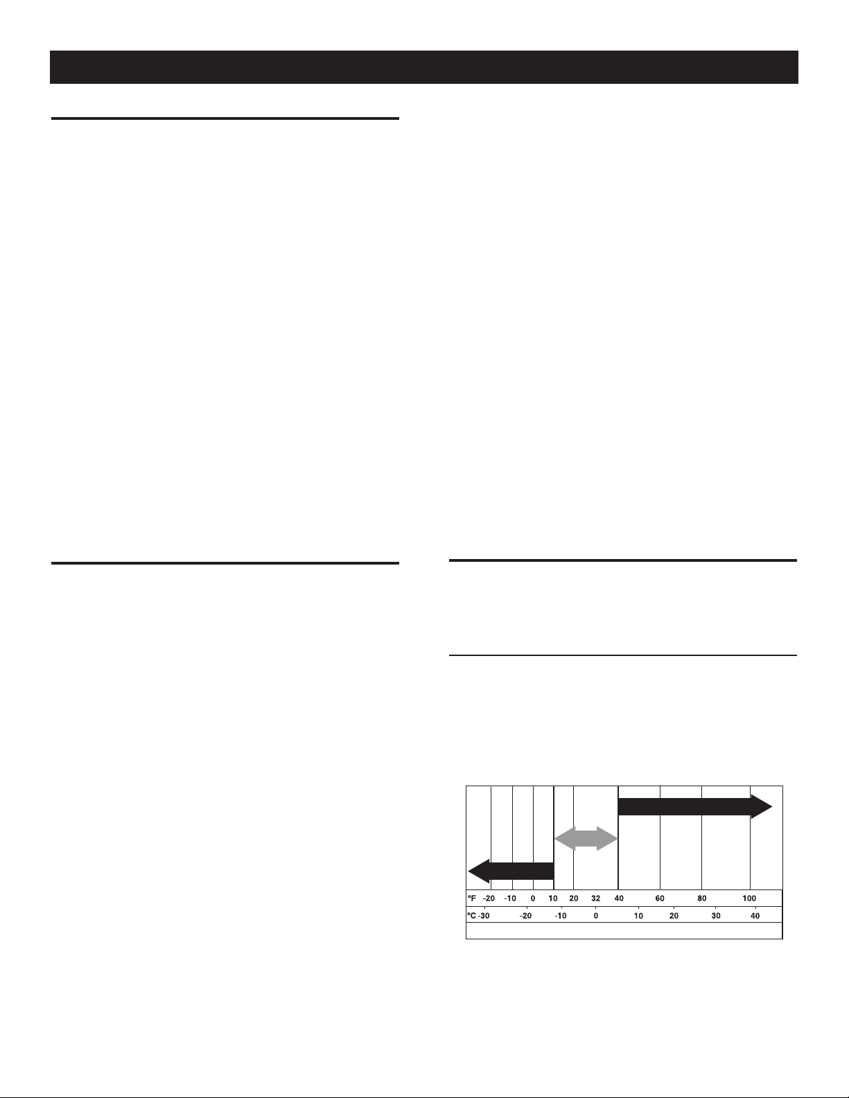
Hu il e sy nt hé tiq ue
5W -3 0
SA E 30
10 W- 30
Fonctionnement
2.5 NE PAS SURCHARGER LE GÉNÉRATEUR
Surcharger un générateur au-dessus de sa capacité nominale de wattage
peut endommager le générateur et les dispositifs électriques branchés.
Respecter les consignes suivantes pour empêcher la surcharge de l'unité :
Calculer le wattage total de tous les dispositifs électriques à brancher •
en même temps. Ce total ne doit PAS dépasser la capacité de wattage
du générateur.
Le wattage nominal des lumières peut être indiqué sur les ampoules. •
Le wattage nominal des outils, des appareils et des moteurs se trouve
généralement sur une étiquette ou un autocollant apposé(e) sur le
dispositif.
Si l'appareil, l'outil ou le moteur n'indique pas le wattage, multiplier la •
valeur nominale des volts fois la valeur nominale des ampères afin de
déterminer les watts (volts x ampères = watts).
Certains moteurs électriques, tels que ceux à induction, nécessitent •
environ trois fois plus de watts d'alimentation pour le démarrage
que pour le fonctionnement. Cette surtension d'alimentation dure
seulement quelques secondes lors du démarrage des moteurs en
question. S'assurer de laisser un wattage de démarrage élevé lors du
choix des dispositifs électriques pour brancher le générateur :
1. Calculer les watts nécessaires pour démarrer le moteur le plus grand.
2. Ajouter à ce chiffre les watts de fonctionnement de toutes les autres
charges branchées.
Le Guide de référence de wattage sert à déterminer combien d'éléments
le générateur peut faire fonctionner en même temps.
REMARQUE :
Tous les chiffres sont arrondis. Voir les étiquettes sur l'unité pour
connaître les exigences de wattage.
Taille-haie . . . . . . . . . . . . . . . . . . . . . . . . . . . . . . . . . . . . .450
Clé à chocs. . . . . . . . . . . . . . . . . . . . . . . . . . . . . . . . . . . .500
Fer . . . . . . . . . . . . . . . . . . . . . . . . . . . . . . . . . . . . . . . . 1 200
*Pompe à jet. . . . . . . . . . . . . . . . . . . . . . . . . . . . . . . . . . .800
Tondeuse à gazon. . . . . . . . . . . . . . . . . . . . . . . . . . . . . 1 200
Ampoule . . . . . . . . . . . . . . . . . . . . . . . . . . . . . . . . . . . . . .100
Four à micro-ondes. . . . . . . . . . . . . . . . . . . . . . . 700 à 1 000
*Refroidisseur de lait . . . . . . . . . . . . . . . . . . . . . . . . . . 1 100
Brûleur à mazout de chaudière . . . . . . . . . . . . . . . . . . . . .300
Radiateur à mazout (140 000 Btu) . . . . . . . . . . . . . . . . . .400
Radiateur à mazout (85 000 Btu) . . . . . . . . . . . . . . . . . . .225
Radiateur à mazout (30 000 Btu) . . . . . . . . . . . . . . . . . . .150
*Pistolet à peinture, sans air (0,3 HP) . . . . . . . . . . . . . . . .600
Pistolet à peinture, sans air (portable). . . . . . . . . . . . . . . .150
Radio . . . . . . . . . . . . . . . . . . . . . . . . . . . . . . . . . . . .50 à 200
*Réfrigérateur . . . . . . . . . . . . . . . . . . . . . . . . . . . . . . . . . .700
Cocotte mijoteuse . . . . . . . . . . . . . . . . . . . . . . . . . . . . . . .200
*Pompe immergée (1,5 HP) . . . . . . . . . . . . . . . . . . . . . 2 800
*Pompe immergée (1 HP). . . . . . . . . . . . . . . . . . . . . . . 2 000
*Pompe immergée (0,5 HP) . . . . . . . . . . . . . . . . . . . . . 1 500
*Pompe de vidange. . . . . . . . . . . . . . . . . . . . . . . 800 à 1 050
*Scie circulaire à table (10 po.) . . . . . . . . . . . .1 750 à 2 000
Télévision . . . . . . . . . . . . . . . . . . . . . . . . . . . . . . . .200 à 500
Grille-pain . . . . . . . . . . . . . . . . . . . . . . . . . . . . .1 000 à 1 650
Coupe-mauvaises herbes . . . . . . . . . . . . . . . . . . . . . . . . .500
* Laisser 3 fois les watts indiqués pour le démarrage de ces
dispositifs.
2.6 GUIDE DE RÉFÉRENCE DE WATTAGE
Dispositif . . . . . . . . . . . . . . . . . . . . Watts de fonctionnement
*Climatiseur (12 000 Btu). . . . . . . . . . . . . . . . . . . . . . . 1 700
*Climatiseur (24 000 Btu). . . . . . . . . . . . . . . . . . . . . . . 3 800
*Climatiseur (40 000 Btu). . . . . . . . . . . . . . . . . . . . . . . 6 000
Chargeur de batterie (20 A). . . . . . . . . . . . . . . . . . . . . . . .500
Ponceuse à bande (3 po.). . . . . . . . . . . . . . . . . . . . . . . 1 000
Scie à chaîne . . . . . . . . . . . . . . . . . . . . . . . . . . . . . . . . 1 200
Scie circulaire (6,5 po.). . . . . . . . . . . . . . . . . . . . 800 à 1 000
*Sèche-linge (électrique). . . . . . . . . . . . . . . . . . . . . . . . 5 750
*Sèche-linge (à gaz) . . . . . . . . . . . . . . . . . . . . . . . . . . . . .700
*Machine à laver. . . . . . . . . . . . . . . . . . . . . . . . . . . . . . 1 150
Cafetière . . . . . . . . . . . . . . . . . . . . . . . . . . . . . . . . . . . . 1 750
*Compresseur (1 HP) . . . . . . . . . . . . . . . . . . . . . . . . . . 2 000
*Compresseur (0,75 HP) . . . . . . . . . . . . . . . . . . . . . . . 1 800
*Compresseur (0,5 HP) . . . . . . . . . . . . . . . . . . . . . . . . 1 400
Fer à friser . . . . . . . . . . . . . . . . . . . . . . . . . . . . . . . . . . . .700
*Déshumidificateur . . . . . . . . . . . . . . . . . . . . . . . . . . . . .650
Ponceuse à disque (9 po.) . . . . . . . . . . . . . . . . . . . . . . 1 200
Coupe-bordures . . . . . . . . . . . . . . . . . . . . . . . . . . . . . . . .500
Couverture chauffante électrique . . . . . . . . . . . . . . . . . . . .400
Cloueuse électrique. . . . . . . . . . . . . . . . . . . . . . . . . . . . 1 200
Cuisinière électrique (par élément). . . . . . . . . . . . . . . . . 1 500
Poêle électrique. . . . . . . . . . . . . . . . . . . . . . . . . . . . . . . 1 250
*Freezer . . . . . . .. . . . . . . . . . . . . . . . . . . . . . . . . . . . . . .700
*Ventilateur de chaudière (0,6 HP) . . . . . . . . . . . . . . . . . .875
*Ouvre-porte de garage . . . . . . . . . . . . . . . . . . . . .500 à 750
Sèche-cheveux . . . . . . . . . . . . . . . . . . . . . . . . . . . . . . 1 200
Perceuse à main . . . . . . . . . . . . . . . . . . . . . . . . . 250 à 1 100
2.7 AVANT LE DÉMARRAGE DU GÉNÉRATEUR
Avant de faire fonctionner le générateur, de l'huile de moteur et de
l'essence devront être ajoutés, de la façon suivante :
2.7.1 AJOUT DE L'HUILE DE MOTEUR
Toute huile doit respecter la catégorie de service minimale SJ, SL ou mieux
de l'American Petroleum Institute (API) (Institut américain du pétrole).
N'utiliser aucun additif spécial. Sélectionner le degré de viscosité d'huile
selon la température d'exploitation (se reporter également au tableau).
Au-dessus de 40 °F, utiliser le SAE 30•
En dessous de 40 °F et jusqu'à 10 °F, utiliser le 10W-30•
En dessous de 10 °F, utiliser le 5W-30 synthétique•
SAE 30
10W-30
Huile synthétique
5W-30
Gamme de température d’utilisation anticipée
45
Page 48

Fonctionnement
ATTENTION !
Toute tentative de faire tourner ou de démarrer le
moteur avant qu'il ait été correctement entretenu
n
avec l'huile recommandée peut entraîner une panne
du moteur.
Installer le générateur sur une surface de niveau.•
Nettoyer l'espace autour de l'orifice de remplissage d'huile et retirer le •
bouchon et la jauge d'huile de l'orifice de remplissage d'huile.
Nettoyer la jauge d'huile.•
Remplir lentement le moteur avec de l'huile par l'orifice de remplissage •
d'huile jusqu'à ce qu'elle atteigne la marque de remplissage. Interrompre
régulièrement le remplissage pour vérifier le niveau d'huile. Faire
attention de ne pas trop remplir.
Mettre le bouchon sur l'orifice de remplissage de l'huile et le serrer •
fermement au doigt.
Vérifier le niveau d'huile de moteur avant le démarrage à chaque fois •
par la suite.
2.7.2 AJOUT DE L'ESSENCE
Ne jamais remplir le réservoir d'essence à l'intérieur.
Ne jamais remplir le réservoir d'essence lorsque le
moteur fonctionne ou est chaud. Éviter de renverser
de l'essence sur un moteur chaud. Laisser le moteur
complètement refroidir avant d'ajouter du carburant.
NE PAS allumer une cigarette ni fumer lors du
remplissage du réservoir d'essence.
Ne pas trop remplir le réservoir d'essence. Toujours
laisser de la place pour l'expansion du carburant.
En cas de suremplissage du réservoir, le carburant
peut déborder sur un moteur chaud et entraîner
un INCENDIE ou une EXPLOSION. Nettoyer
immédiatement toute éclaboussure de carburant.
Ne pas allumer une cigarette ni fumer lors du
remplissage du réservoir d'essence. L'essence est
extrêmement INFLAMMABLE et ses vapeurs sont
EXPLOSIVES.
Utiliser de l'essence SANS PLOMB régulière avec le moteur du •
générateur. Ne pas utiliser d'essence avec plus de 10 % d'éthanol ajouté.
Ne pas utiliser d'essence E85. Ne pas mélanger l'huile avec l'essence.
Nettoyer l'espace autour du bouchon de l'orifice de remplissage •
d'essence, retirer le bouchon.
Ajouter lentement de l'essence régulière sans plomb dans le réservoir •
d'essence. Remplir jusqu'au fond du filtre à tamis. Faire attention de
ne pas trop remplir (Schéma 8).
Mettre le bouchon du réservoir d'essence et nettoyer toute éclaboussure •
d'essence.
IMPORTANT : Il est important d'empêcher la formation de dépôts de
gomme dans les pièces du circuit de carburant, telles que le carburateur, le
tuyau pour combustible ou le réservoir pendant le stockage. L'expérience
montre également que les carburants à base d'alcool (appelés gazohol,
éthanol ou méthanol) peuvent absorber l'humidité, ce qui entraîne une
séparation et la formation d'acides pendant le stockage. Un gaz acide
peut endommager le circuit de carburant d'un moteur pendant le stockage
de celui-ci. Afin d'éviter tout problème avec le moteur, le circuit de
carburant doit être vidé avant le stockage du moteur si celui-ci est d'au
moins 30 jours. Voir la section « Stockage ». Ne jamais utiliser de produit
nettoyant pour moteur ou carburateur dans le réservoir d'essence étant
donné que cela pourrait causer des dommages permanents.
2.8
DÉMARRAGE DES MOTEURS À DÉMARRAGE MANUEL
AVERTISSEMENT !
Ne jamais démarrer ou arrêter le moteur avec
les dispositifs électriques branchés dans les
prises ET les dispositifs sous tension.
Débrancher toutes les charges électriques des prises de l'unité avant •
de démarrer le moteur.
S'assurer que l'unité est dans une position de niveau.•
OUVRIR• la soupape d'arrêt (Schéma 9).
Mettre l'interrupteur RUN/STOP (Marche/Arrêt) du moteur sur la •
position ON (Marche).
Faire glisser l'étrangleur du moteur de la position LEFT (Gauche) vers •
la position FULL CHOKE (Étrangleur plein) (Schéma 10).
Pour démarrer le moteur, attraper fermement la poignée de rappel et •
tirer jusqu'à ce qu'une résistance se fasse sentir. Remonter rapidement
et démarrer.
Lorsque le moteur démarre, mettre le bouton Choke (Étrangleur) sur •
la position 1/2 CHOKE (Étrangleur à moitié) jusqu'à ce que le moteur
fonctionne doucement et ensuite sur la position RUN (Marche). Si
le moteur vibre, remettre le levier Choke (Étrangleur) sur la position
1/2 CHOKE (Étrangleur à moitié) jusqu'à ce que le moteur fonctionne
doucement et ensuite sur la position RUN (Marche).
REMARQUE :
Si le moteur chauffe, mais ne continue pas à fonctionner, mettre le
levier de l'étrangleur sur FULL CHOKE (Étrangleur plein) et répéter les
instructions de démarrage.
Schéma 9 - Soupape d'arrêt
46
Schéma 8 - Réservoir d'essence
Réservoir de carburant
NE PAS remplir au-
Carburant
dessus de la lèvre
SOUPAPE D'ARRÊT
Page 49

Maintenance
Schéma 10 - Position de l'étrangleur
LEVIER D'ÉTRANGLEUR
GAUCHE = ÉTRANGLEUR
DROITE = FONCTIONNEMENT
IMPORTANT : Ne pas surcharger le générateur. Aussi, ne pas surcharger
les prises individuelles du panneau. Ces prises sont protégées contre la
surcharge avec des disjoncteurs de type « pousser pour réenclencher ».
Si la valeur nominale d'ampérage d'un disjoncteur est dépassée, ce
disjoncteur s'ouvre et la puissance électrique de cette prise est perdue.
Lire attentivement la section « Ne pas surcharger le générateur ».
2.9 DÉMARRAGE DES MOTEURS À DÉMARRAGE ÉLECTRIQUE
AVERTISSEMENT !
Ne jamais démarrer ou arrêter le moteur avec les
dispositifs électriques branchés dans les prises ET
les dispositifs sous tension.
Débrancher toutes les charges électriques des prises de l'unité avant •
de démarrer le moteur.
S'assurer que l'unité est dans une position de niveau.•
Ouvrir la soupape d'arrêt (Schéma 9).•
Mettre le bouton CHOKE (Étrangleur) du moteur à l'extérieur sur la •
position « Full Choke » (Étrangleur plein) (Schéma 10).
Pour démarrer le moteur, appuyer et maintenir enfoncé l'interrupteur •
Start/Run/Stop (Démarrage/Marche/Arrêt) sur la position « Start »
(Démarrage). Le moteur tournera et commencera à démarrer. Lorsque le
moteur démarre, relâcher l'interrupteur sur la position Run (Marche).
Lorsque le moteur démarre, mettre le bouton Choke (Étrangleur) sur la •
position « 1/2 Choke » (Étrangleur à moitié) jusqu'à ce que le moteur
fonctionne doucement et ensuite sur la position « Run » (Marche). Si
le moteur vibre, remettre le bouton Choke (Étrangleur) sur la position
« 1/2 Choke » (Étrangleur à moitié) jusqu'à ce que le moteur fonctionne
doucement et ensuite sur la position « Run » (Marche).
Ce générateur est également équipé d'un lanceur à rappel manuel qui •
peut être utilisé en cas de déchargement de la batterie.
REMARQUE :
L'interrupteur doit être en position RUN (Marche).
Pour démarrer manuellement, attraper fermement la poignée de rappel et •
tirer jusqu'à ce qu'une résistance se fasse sentir. Remonter rapidement
et démarrer le moteur. Puis, suivre la même séquence de l'étrangleur.
REMARQUE :
Si le moteur chauffe, mais ne continue pas à fonctionner, mettre le
levier de l'étrangleur sur FULL CHOKE (Étrangleur plein) et répéter les
instructions de démarrage.
IMPORTANT : Ne pas surcharger le générateur. Aussi, ne pas surcharger
les prises individuelles du panneau. Ces prises sont protégées contre la
surcharge avec des disjoncteurs de type « pousser pour réenclencher ».
Si la valeur nominale d'ampérage d'un disjoncteur est dépassée, ce
disjoncteur s'ouvre et la puissance électrique de cette prise est perdue.
Lire attentivement la section « Ne pas surcharger le générateur ».
2.10 ARRÊT DU MOTEUR
Arrêter toutes les charges, puis débrancher les charges électriques •
des prises du panneau du générateur. Ne jamais démarrer ou arrêter le
moteur avec les dispositifs électriques branchés et sous tension.
Laisser le moteur fonctionner à circuit ouvert pendant plusieurs •
minutes pour stabiliser les températures internes du moteur et du
générateur.
Mettre l'interrupteur Run/Stop (Marche/Arrêt) sur la position • OFF (Arrêt).
Fermer la vanne de combustible.•
2.11 SYSTÈME D'ARRÊT DE BAS NIVEAU D'HUILE
Le moteur est équipé d'un détecteur de bas niveau d'huile qui arrête le
moteur automatiquement lorsque le niveau d'huile chute en dessous
d'un niveau spécifique. Si le moteur s'arrête tout seul et que le réservoir
d'essence a assez d'essence, vérifier le niveau d'huile du moteur.
2.11.1 DÉTECTION DE BAS NIVEAU D'HUILE
Si le système détecte un niveau d'huile bas pendant le fonctionnement, le
moteur s'arrête. Le moteur ne fonctionnera pas tant que de l'huile n'aura
pas été rajoutée pour atteindre le bon niveau.
3.1 PROGRAMME DE MAINTENANCE
Suivre les intervalles du calendrier. Un entretien plus fréquent est
nécessaire lors du fonctionnement dans les conditions défavorables
indiquées ci-dessous.
Vérifier le niveau d'huile Lors de chaque utilisation
Changer l'huile ‡ *Toutes les 100 heures ou à chaque saison
Vérifier le jeu des soupapes ***À chaque saison
Entretien du filtre à air ** Toutes les 200 heures ou à chaque
saison
Remplacer la bougie d'allumage À chaque saison
‡ Changer l'huile après les 30 premières heures de fonctionnement puis à chaque
saison.
* Changer l'huile et le filtre à huile tous les mois lors du fonctionnement sous une
charge lourde ou à des températures élevées.
** Nettoyer plus souvent dans des conditions de fonctionnement sales. Remplacer
les pièces du filtre à air s'il est impossible de les nettoyer correctement.
*** Vérifier le jeu des soupapes et régler si nécessaire après les 50 premières
heures de fonctionnement et toutes les 100 heures par la suite.
47
Page 50

Maintenance
3.2
CARACTÉRISTIQUES TECHNIQUES DES PRODUITS
3.2.1
CARACTÉRISTIQUES TECHNIQUES DU GÉNÉRATEUR
Puissance nominale ......................................... 5/ 5,5/ 6,5 kW**
Puissance de surtension .................................. 6,25/ 6,88/ 8 kW
Tension c.a. nominale ....................................................120/240
Charge c.a. nominale.
Courant à 240 V (5/ 5,5/ 6,5 kW) ............ 20,8/ 22,9/ 27,1 A**
Courant à 120 V (5/ 5,5/ 6,5 kW) ............ 41,6/ 45,8/ 54,2 A**
Fréquence nominale ..................................... 60 Hz à 3 600 RPM
Phase ..................................................................... Monophasée
** Le wattage et le courant maximum sont soumis à, et limités par, ces facteurs
tels que le contenu en Btu de carburant, la température ambiante, l'altitude,
l'état du moteur, etc. La puissance maximale diminue d'environ 3,5 % pour
chaque tranche de 1 000 pieds au-dessus du niveau de la mer ; et diminuera
également d'environ 1 % pour chaque tranche de 6 °C (10 °F) au-dessus de
16 °C (60 °F) de température ambiante.
3.2.2 CARACTÉRISTIQUES TECHNIQUES DU MOTEUR
Déplacement .................................................................... 389 cc
Type de bougie d'allumage .....NHSP LDF7TC ou Champion N9YC
Écartement de bougie d'allumage ......... 0,028 - 0,031 pouces ou
(0,70 0,80 mm)
Capacité d'essence ............................................ 7,2 gallons U.S.
Type d'huile .....Voir tableau dans la section « Avant le démarrage
du
générateur »
Capacité d'huile ....................................................1 L (1,06 Qts.)
Temps d'exécution à une charge de 50 % (5/ 5,5/ 6,5 kW) ..........
10 heures
3.2.3 INFORMATIONS RELATIVES AUX ÉMISSIONS
L'Agence pour la protection de l'environnement (EPA) exige que ce
générateur soit conforme aux normes en matière d'émission d'échappement.
Ce générateur est certifié comme respectant tous les niveaux d'émission
d'échappement EPA applicables. Il est important de respecter les
spécifications de maintenance indiquées dans ce manuel afin de s'assurer
que votre moteur est conforme aux normes applicables en matière
d'émission pendant la durée de vie du moteur. Le système de contrôle des
émissions de ce générateur est composé des éléments suivants :
Système d'induction d'air • Système d'allumage•
~ Pipe / collecteur d'admission ~ Bougie d'allumage
~ Filtre à air ~ Bobine d'allumage
Système d'échappement • Système de carburant•
~ Collecteur d'échappement ~ Carburateur
~ Pot d'échappement
La période de conformité des émissions à laquelle il est fait référence
sur l'étiquette de conformité des émissions indique le nombre d'heures
de fonctionnement pendant lesquelles le moteur a prouvé respecter les
exigences EPA en matière d'émission.
3.3 RECOMMANDATIONS GÉNÉRALES
La garantie du générateur ne couvre pas les éléments qui ont été soumis
à un abus ou une négligence de l'opérateur. Afin de recevoir le montant
total de la garantie, l'opérateur doit entretenir le générateur de la façon
indiquée dans ce manuel.
Certains réglages doivent être effectués régulièrement pour entretenir
correctement le générateur.
Tous les réglages de la section Maintenance de ce manuel doivent être
effectués au moins une fois par saison. Respecter les exigences dans le
tableau de « Programme de maintenance ».
Une fois par an, remplacer la bougie d'allumage et le filtre à air. Une
nouvelle bougie d'allumage et un filtre à air propre garantissent un
bon mélange carburé et aide le moteur à mieux fonctionner et à durer
plus longtemps.
3.3.1 MAINTENANCE DU GÉNÉRATEUR
La maintenance du générateur consiste à garder l'unité propre et sèche.
Faire fonctionner et stocker l'unité dans un environnement sec et propre
où il ne sera pas exposé à trop de poussières, de saletés, d'humidité ou de
vapeurs corrosives. Les fentes de refroidissement du générateur ne doivent
pas être obstruées par la neige, les feuilles ou tout autre corps étranger.
Vérifier régulièrement que le générateur est propre et nettoyer la poussière,
les saletés, l'huile, l'eau ou les autres corps étrangers qui sont visibles sur
sa surface extérieure.
Ne jamais insérer d'objet ou d'outil dans les fentes de
refroidissement, même si le moteur ne fonctionne pas.
n
NE PAS utiliser un tuyau d'arrosage pour nettoyer le générateur. L'eau
peut entrer dans le système de carburant du moteur et causer des
problèmes. En outre, si l'eau entre dans le générateur par les fentes
de refroidissement, de l'eau restera dans les vides et les crevasses
du bobinage d'isolement du rotor et du stator. L'accumulation d'eau
et de saletés sur les bobinages internes du générateur diminuera
potentiellement la résistance d'isolement de ces bobinages.
3.3.2 NETTOYAGE DU GÉNÉRATEUR
Utiliser un chiffon humide pour le nettoyage des surfaces externes.•
Il est possible d'utilise une brosse douce en poils pour décoller les •
agglutinements de saletés, d'huile, etc.
Un aspirateur pourra être utilisé pour récupérer les saletés et les débris.•
Un air projeté avec une faible pression (inférieur à 25 livres par pouce •
carré) pourra être utilisé pour souffler la saleté. Inspecter les fentes de
refroidissement et les orifices du générateur. Ces orifices doivent être
propres et non obstrués.
3.3.3 MAINTENANCE DU MOTEUR
REMARQUE :
ATTENTION !
REMARQUE :
48
Toujours débrancher le fil de bougie de la bougie
d'allumage et rester à distance de celui-ci en cas de
travail sur le générateur.
Page 51

Maintenance
3.3.4 VÉRIFICATION DU NIVEAU D'HUILE
Se reporter à la section « Avant le démarrage du générateur » pour plus
d'informations sur la vérification du niveau d'huile. Le niveau d'huile doit être
vérifié avant chaque utilisation, ou au minimum toutes les huit heures de
fonctionnement. Il est nécessaire de conserver un certain niveau d'huile.
3.3.5 CHANGEMENT DE L'HUILE
Changer l'huile toutes les 100 heures. Changer l'huile plus souvent en cas
d'utilisation de cette unité dans un environnement sale ou poussiéreux, ou
dans des températures très élevées.
ATTENTION !
De l'huile chaude peut entraîner des brûlures.
Laisser le moteur refroidir avant de vidanger l'huile.
n
Éviter un contact prolongé ou répété de la peau
avec de l'huile usagée. Laver minutieusement les
zones exposées avec du savon.
Respecter les instructions suivantes pour changer l'huile après que le
moteur ait refroidi :
Nettoyer la zone autour du tuyau de vidange d'huile.•
Retirer le bouchon de vidange d'huile du moteur et le bouchon pour le •
remplissage d'huile afin de vidanger toute l'huile dans un récipient adapté.
Lorsque l'huile est totalement vidangée, revisser le bouchon de vidange •
d'huile et le resserrer solidement.
Remplir le moteur avec l'huile recommandée. (voir la section « Avant •
le démarrage du générateur » pour les recommandations sur l'huile
à utiliser).
Nettoyer toute trace d'huile renversée.•
Éliminer l'huile usagée dans un centre de collecte approprié.•
3.4 ENTRETIEN DU FILTRE À AIR
Le moteur ne fonctionnera pas correctement et pourra être endommagé
en cas d'utilisation d'un filtre à air sale. Nettoyer le filtre à air toutes les
200 heures ou une fois par an (Schéma 12). Il sera nécessaire de le
nettoyer ou de le remplacer plus souvent en cas de fonctionnement dans
des conditions de saleté.
Retirer le couvercle du filtre à air.•
Laver dans une eau savonneuse. Le presser dans un chiffon propre •
pour le sécher (NE PAS LE TORDRE).
Nettoyer le couvercle du filtre à air avant de le remettre en place.•
REMARQUE :
Pour commander un nouveau filtre à air, merci de contacter le centre
d'entretien agréé le plus proche au 1-800-436-1322.
Schéma 12 - Filtre à air
3.3.6 REMPLACEMENT DES BOUGIES D'ALLUMAGE
Utiliser des bougies d'allumage Champion N9YC ou équivalent.
Remplacer les bougies une fois par an. Cela permettra un démarrage
plus facile et un meilleur fonctionnement du moteur.
1. Arrêter le moteur et débrancher le fil de bougie de la bougie
d'allumage.
2. Nettoyer la zone autour de la bougie d'allumage et la retirer de la
culasse.
3. Régler l'écartement de bougie d'allumage à 0,70 - 0,80 mm (0,028 0,031 po.). Installer la bougie d'allumage correctement écartée dans
la culasse (Schéma 11).
Schéma 11 - Écartement de la bougie d'allumage
3.5 JEU DES SOUPAPES
Admission — 0,15 ± 0,02 mm (froid), (0,006 ± 0,0008 pouces)•
Échappement — 0,0020 ± 0,02 mm (froid), (0,008 ± •
0,0008 pouces)
Vérifier le jeu des soupapes dans le moteur après les 50 premières
heures de fonctionnement et l'ajuster si cela est nécessaire.
IMPORTANT : En cas de doute quant à la réalisation de cette procédure,
ou d'absence des outils adaptés, merci de faire régler le jeu des soupapes
du générateur dans le centre de réparation le plus proche. Il s'agit d'une
étape très importante pour garantir la meilleure durée de vie du moteur.
49
Page 52

Maintenance
3.6 GÉNÉRALITÉS
Le générateur doit être démarré au moins une fois par semaine et doit
fonctionner pendant au moins 30 minutes. Si cela est impossible et que
l'unité n'est pas utilisée pendant plus de 30 jours, utiliser les informations
suivantes en tant que guide pour préparer son stockage.
NE JAMAIS ranger le moteur avec un réservoir rempli
d'essence à l'intérieur ou dans des zones fermées et
faiblement aérées où des fumées peuvent atteindre
une flamme nue, des étincelles ou une veilleuse telle
qu'il y en a sur une chaudière, un chauffe-eau, un
sèche-linge ou d'autres appareils fonctionnant au
gaz.
Laisser l'unité complètement refroidir avant le stockage.
n
3.7 STOCKAGE À LONG TERME
Pendant le stockage, il est important d'empêcher la formation de dépôts de
gomme dans les pièces essentielles du circuit de carburant, telles que le
carburateur, le tuyau pour combustible ou le réservoir. L'expérience montre
également que les carburants à base d'alcool (appelés gazohol, éthanol ou
méthanol) peuvent absorber l'humidité, ce qui entraîne une séparation et la
formation d'acides pendant le stockage. Un gaz acide peut endommager le
circuit de carburant d'un moteur pendant le stockage de celui-ci.
Afin d'éviter tout problème avec le moteur, le circuit de carburant doit être vidé
avant le stockage du moteur si celui-ci est d'au moins 30 jours. Pour cela :
Vidanger le réservoir d'essence de tout le carburant qu'il contient.•
ATTENTION !
Éviter d'asperger à partir des trous de la
bougie d'allumage lorsque le moteur tourne.
n
Remettre et serrer la bougie d'allumage. Ne pas brancher le fil de •
bougie.
Nettoyer les surfaces externes du générateur. Vérifier que les fentes •
de refroidissement et les orifices du générateur sont ouverts et non
obstrués.
Stocker l'unité dans un endroit propre et sec.•
3.8 AUTRES CONSEILS DE STOCKAGE
Ne pas stocker l'essence d'une saison sur l'autre.•
Remplacer le bidon d'essence s'il commence à rouiller. De la rouille •
et / ou de la saleté dans l'essence entraîneront des problèmes dans le
carburateur et le circuit de carburant.
Si cela est possible, stocker l'unité à l'intérieur et la recouvrir afin de •
la protéger de la saleté et de la poussière. S'ASSURER DE VIDER LE
RÉSERVOIR D'ESSENCE.
S'il n'est pas possible de vider le réservoir d'essence et que l'unité est •
rangée pendant une longue période, ajouter un stabilisateur d'essence
(disponible dans le commerce) à l'essence afin d'augmenter la durée
de vie de l'essence.
Couvrir l'unité avec une protection adaptée ne retenant pas l'humidité.•
NE JAMAIS couvrir le générateur alors que le
moteur et la zone du pot d'échappement sont
n
chauds.
Vider l'essence dans des conteneurs adaptés situés à
l'extérieur, loin de toute flamme nue. S'assurer que le
moteur est froid. Ne pas fumer.
Démarrer et faire fonctionner le moteur jusqu'à ce qu'il s'arrête suite à •
une panne d'essence.
Vidanger le carter pendant que le moteur est encore chaud. Remplir •
jusqu'au niveau recommandé.
Retirer la bougie d'allumage et verser environ 0,5 onces (15 ml) d'huile •
pour moteur dans le cylindre. Couvrir l'orifice de la bougie d'allumage
avec un chiffon. Tirer plusieurs fois le lanceur à rappel pour lubrifier les
segments de piston et l'alésage du cylindre.
50
Page 53

4.1 GUIDE DE DÉPANNAGE
PROBLÈME CAUSE SOLUTION
Le moteur tourne, mais aucun
courant alternatif n'est produit.
1. Disjoncteur est ouvert.
2. Cordon mal branché ou défectueux.
3. Dispositif branché défectueux.
4. Erreur au niveau du générateur.
1. Réarmer le disjoncteur.
2. Vérifier et réparer.
3. Brancher un autre dispositif en bon état.
4. Contacter un centre d'entretien agréé.
Remarques
Dépannage
Le moteur fonctionne bien mais
connaît des défaillances lorsque
des charges sont branchées.
Le moteur ne démarre pas,
ou démarre et connaît des
défaillances.
Le moteur s'arrête pendant le
fonctionnement.
1. Court-circuit dans l'une des charges branchées.
2. Surcharge du générateur.
3. Vitesse du moteur trop faible.
4. Court-circuit du générateur.
1. La soupape d'arrêt est sur OFF (Arrêt).
2. Filtre à air sale.
3. Panne d'essence.
4. Essence viciée.
5. Fil de bougie débranché de la bougie d'allumage.
6. Bougie d'allumage défectueuse.
7. Présence d'eau dans l'essence.
8. Étranglement important.
9. Niveau d'huile faible.
10. Mélange d'essence trop riche.
11. Soupape d'admission bloquée en position ouverte
ou fermée.
12. Perte de compression du moteur.
1. Panne d'essence.
2. Niveau d'huile faible.
3. Erreur au niveau du moteur.
1. Débrancher la charge électrique court-circuitée.
2. Voir la section « Ne pas surcharger le générateur ».
3. Contacter un centre d'entretien agréé.
4. Contacter un centre d'entretien agréé.
1. Mettre la soupape d'arrêt sur ON (Marche).
2. Nettoyer ou remplacer le filtre à air.
3. Remplir le réservoir d'essence.
4. Vidanger le réservoir d'essence et le remplir avec
de l'essence nouvelle.
5. Brancher le fil à la bougie d'allumage.
6. Remplacer la bougie d'allumage.
7. Vidanger le réservoir d'essence et le remplir avec
de l'essence nouvelle.
8. Placer le levier d'étrangleur sur la position No
Choke (Aucun étrangleur).
9. Remplir le carter jusqu'au niveau nécessaire.
10. Contacter un centre d'entretien agréé.
11. Contacter un centre d'entretien agréé.
12. Contacter un centre d'entretien agréé.
1. Remplir le réservoir d'essence.
2. Remplir le carter jusqu'au niveau nécessaire.
3. Contacter un centre d'entretien agréé.
Moteur pas assez puissant. 1. Charge trop élevée.
2. Filtre à air sale.
3. Réparation nécessaire du moteur.
À-coups ou déclin du moteur. 1. Étrangleur ouvert trop tôt.
2. Mélange trop riche ou trop pauvre dans le
carburateur.
1. Diminuer la charge (voir la section « Ne pas
surcharger le générateur »).
2. Nettoyer ou remplacer le filtre à air.
3. Contacter un centre d'entretien agréé.
1. Placer le levier d'étrangleur à mi-chemin jusqu'à ce
que le moteur fonctionne correctement.
2. Contacter un centre d'entretien agréé.
51
Page 54

Garantie
ÉNONCÉ DE LA GARANTIE FÉDÉRALE DU CONTRÔLE DES ÉMISSIONS
VOS DROITS ET OBLIGATIONS DE GARANTIE
L'Agence pour la Protection de l'Environnement américaine (ci-après dénommée EPA) et la société Generac Power Systems, Inc.
(ci-après dénommée Generac) sont heureux de vous expliquer ce qu'est la garantie de votre nouvel équipement 2008 et ultérieur.
Le nouvel équipement utilise des petits moteurs à allumage commandé doivent être conçus, construits et équipés dans le respect
des normes nationales rigoureuses en matière de pollution pour le gouvernement fédéral. Generac garantira le système de
contrôle des émissions de votre générateur pour les périodes indiquées ci-après, en l'absence d'acte abusif, de négligence, de
modification non approuvée ou de maintenance inadaptée de votre équipement.
Votre système de contrôle des émissions pourra comprendre certaines pièces telles que : le carburateur, le système d'allumage, le
système de carburant, le pot catalytique et les autres composants relatifs aux émissions (le cas échéant).
COUVERTURE DE GARANTIE DU FABRICANT :
Ce système de contrôle des émissions est garanti pendant une durée de deux ans. Si un composant ou système de votre
équipement relatif aux émissions comporte une pièce défectueuse ou présente un défaut de fabrication pendant la durée de
la garantie, les réparations ou remplacements de pièces seront effectués par un dépositaire d'entretien de garantie agréé par
Generac.
RESPONSABILITÉS DE GARANTIE DU PROPRIÉTAIRE :
En tant que propriétaire du générateur, vous êtes responsable de la réalisation de toute la maintenance nécessaire telle que listée
dans le manuel d'entretien qui vous a été remis par l'usine. Aux fins de la garantie, Generac vous recommande de conserver tous
les reçus relatifs à la maintenance effectuée sur votre générateur, mais Generac ne peut pas refuser la garantie uniquement en
raison de la non-présentation des reçus.
En tant que propriétaire du générateur, vous devez cependant savoir que Generac pourra refuser tout et / ou partie de la
couverture de la garantie ou de la responsabilité si votre générateur et / ou toute pièce de celui-ci ne fonctionne plus du fait d'un
usage abusif, d'une négligence, d'une mauvaise maintenance ou de modifications non approuvées, ou de l'utilisation de pièces
contrefaites et / ou provenant de l'économie souterraine n'ayant pas été fabriquées, fournies ou approuvées par Generac.
Vous êtes chargé de contacter un dépositaire de garantie agréé par Generac dès qu'un problème se présente. Les
réparations effectuées dans le cadre de la garantie devront être faites dans une période raisonnable, inférieure à 30 jours.
Le service de garantie peut être organisé en contactant votre dépositaire ou un dépositaire de service de garantie agréé par
Generac. Pour connaître le dépositaire de service de garantie agréé par Generac situé le plus près, appeler notre numéro gratuit :
1-800-333-1322
REMARQUE IMPORTANTE : Cet énoncé de garantie explique vos droits et obligations dans le cadre de la garantie du Système
de Contrôle des Émissions (garantie du SCE) qui vous est fournie par Generac conformément au droit de l'État fédéral. Consulter
également les « Garanties limitées de Generac pour Generac Power Systems, Inc. » jointes au présent document sur un feuillet
séparé, qui vous est également remis par Generac. Veuillez noter que la présente garantie ne s'applique pas aux dommages
accessoires, importants ou indirects causés par des défaillances matérielles ou de fabrication, ou par tout retard de réparation ou de
remplacement de la ou des pièce(s) défectueuses. La présente garantie remplace toutes les autres garanties, implicites ou explicites.
En particulier, Generac n'émet aucune garantie de conformité ou d'usage pour un objectif particulier. Certains états ne permettent pas
de poser une limite à la durée de la garantie implicite, la limite susmentionnée ne s'applique donc pas à ces derniers.
La garantie du SCE ne s'applique qu'au système de contrôle des émissions de votre nouvel équipement. En cas de conflit au
niveau des termes de la présente garantie du SCE et de la garantie Generac, la garantie de Generac prévaudra. Les garanties du
SCE et de Generac décrivent les droits et obligations importantes relatives à votre nouvel équipement.
Le service de garantie ne peut être réalisé que par une entreprise de service agréée par Generac. En cas de demande du service
de garantie, des preuves mentionnant la date de vente à l'acquéreur / au propriétaire d'origine doivent être présentées.
Pour toute question concernant vos droits et responsabilités de garantie, merci de contacter Generac à l'adresse suivante :
ATTENTION WARRANTY DEPARTMENT
GENERAC POWER SYSTEMS, INC.
P.O. BOX 297 • WHITEWATER, WI 53190
1ère partie
Référence 0H1911 Rév. A 01/09
52
Page 55

Garantie
GARANTIE DU SYSTÈME DE CONTRÔLE DES ÉMISSIONS
Garantie du Système de Contrôle des Émissions (garantie du SCE) pour l'équipement utilisant de petits moteurs à allumage commandé :
(a) Applicabilité : La présente garantie s'applique à l'équipement qui utilise de petits moteurs hors route. La période de la garantie
du SCE commencera à la date d'achat / de livraison du nouvel équipement à son acquéreur / propriétaire d'origine, final, et
durera pendant les 24 mois suivant ladite date.
(b) Couverture de la garantie générale des émissions : Generac garantit à l'acquéreur / au propriétaire d'origine, final, du nouveau
moteur ou équipement et à chacun des acquéreurs / propriétaires suivant que lorsqu'il est installé le SCE :
(1) Est conçu, construit et équipé dans le respect de toutes les réglementations applicables ; et
(2) Ne comporte aucune pièce défectueuse ni ne présente aucun défaut de fabrication à tout moment de la période de
(c) La garantie sur les pièces relatives aux émissions sera interprétée de la façon suivante :
(1) Toute pièce garantie, dont le remplacement n'est pas prévu au cours des maintenances obligatoires mentionnées dans
(2) Toute pièce garantie dont il est prévu une inspection régulière dans le Manuel d'entretien sera garantie pendant toute la
(3) Toute pièce garantie, dont le remplacement est pas prévu au cours des maintenances obligatoires mentionnées dans le
(4) La réparation ou le remplacement de toute pièce relative aux émissions et garantie dans le cadre de la Garantie du SCE
(5) Nonobstant les dispositions de la sous-section (4) ci-dessus, les services ou réparations sous garantie doivent être
(6) Si le moteur est inspecté par un service de garantie agréé par Generac, les frais de diagnostic ne seront pas à la charge
(7) Generac est tenu, pendant la durée de la Garantie du SCE, de conserver un stock de pièces relatives aux émissions et
(8) Toute pièce de rechange relative aux émissions agréée et approuvée par Generac pourra être utilisée pour la réalisation
(9) Toute pièce non approuvée, ajoutée, modifiée, contrefaite et / provenant de l'économie souterraine ne pourra pas être
garantie du SCE.
le Manuel d'entretien sera garantie pour toute la durée de la Garantie du SCE. Si l'une de ces pièces devient défectueuse
pendant la durée de la Garantie du SCE, elle sera réparée ou remplacée par Generac conformément au paragraphe (4)
qui suit. Ces pièces réparées ou remplacées dans le cadre de la Garantie du SCE seront garanties pour le reste de la
durée de la Garantie du SCE.
durée de la Garantie du SCE. Toute déclaration contenue dans le Manuel d'entretien et relative à l'effet de « réparation ou
remplacement si nécessaire » ne réduira pas la durée de la Garantie du SCE. Ces pièces réparées ou remplacées dans le
cadre de la Garantie du SCE seront garanties pour le reste de la durée de la Garantie du SCE.
Manuel d'entretien sera garantie pour la période précédant la date du premier remplacement prévu. Si la pièce devient
défectueuse avant le premier remplacement prévu, elle sera réparée ou remplacée par Generac, conformément au
paragraphe (4) qui suit. Ces pièces relatives aux émissions réparées ou remplacées dans le cadre de la Garantie du SCE
seront garanties pour le reste de la durée précédant la date de leur premier remplacement prévu.
sera réalisé sans frais pour le propriétaire dans un service de garantie agréé par Generac.
effectués aux centres d'entretien agréés Generac.
de l'acquéreur / du propriétaire si la réparation entre dans le cadre de la garantie.
garanties suffisant afin de répondre à la demande desdites pièces.
de toute maintenance ou réparation effectuée dans le cadre de la garantie du SCE et sera fournie sans frais à la charge de
l'acquéreur / du propriétaire. Cette utilisation ne réduira pas les obligations de Generac dans le cadre de la Garantie du SCE.
utilisée afin de modifier ou de réparer un moteur Generac. L'utilisation de telles pièces annule la Garantie du SCE
et constituera un motif suffisant pour rejeter toute demande de bénéfice de la Garantie du SCE. Generac ne sera
pas responsable des défaillances des pièces garanties d'un équipement Generac dues à l'utilisation de pièces non
approuvées, ajoutées, modifiées contrefaites et / ou provenant de l'économie souterraine.
LES PIÈCES RELATIVES AUX ÉMISSIONS PEUVENT INCLURE CE QUI SUIT
1) SYSTÈME DE DOSAGE DU CARBURANT
A. CARBURATEUR ET PIÈCES INTERNES
B. RÉGULATEUR DE PRESSION
2) SYSTÈME D'INDUCTION D'AIR
A. COLLECTEUR D'ADMISSION
B. FILTRE À AIR
3) SYSTÈME D'ALLUMAGE
A. BOUGIES D'ALLUMAGE
B. BOBINES / MODULE D'ALLUMAGE
2ème partie
(LE CAS ÉCHÉANT) :
4) SYSTÈME D'INJECTION D'AIR
A. VANNE À IMPULSION D'AIR
5) SYSTÈME D'ÉCHAPPEMENT
A. CATALYSEUR
B. RÉACTEUR THERMIQUE
C. COLLECTEUR D'ÉCHAPPEMENT
Référence 0H1911 Rév. A 01/09
53
Page 56

Garantie
GARANTIE LIMITÉE DE DEUX ANS DE GENERAC POWER SYSTEMS POUR
LES GÉNÉRATEURS PORTABLES SÉRIE GP
La société Generac Power Systems, Inc. (Generac) garantit que, pendant une période de deux années à compter de la date d'achat d'origine, ses générateurs série GP ne
présenteront aucun défaut matériel ni de fabrication pour les éléments et la période mentionnée ci-après. Generac réparera ou remplacera, comme il le jugera nécessaire, toute
pièce jugée défectueuse après un examen, une inspection et un test réalisés par Generac ou un dépositaire de service de garantie agréé par Generac. Tout équipement déclaré
défectueux par l'acquéreur / le propriétaire doit être retourné et examiné par le dépositaire de service de garantie agréé par Generac le plus proche. Tous les frais d'envoi à
payer dans le cadre de la garantie, dont le retour à l'usine, seront supportés et payés à l'avance par l'acquéreur / le propriétaire. Cette garantie ne s'applique qu'aux générateurs
portables de la série GP et n'est pas transférable par l'acquéreur d'origine. Il est conseillé de conserver les preuves d'achat. Si vous ne fournissez pas de preuve de la date
d'achat d'origine, la date d'envoi du produit par son fabricant servira à déterminer la période de garantie.
PROGRAMME DE GARANTIE
Les applications des clients sont garanties pendant deux (2) ans. Les applications commerciales et de location sont garanties pendant un (1) an ou 1 000 heures maximum, à
la première des deux dates.
APPLICATION DES CLIENTS
ANNÉE UNE – couverture à 100 % (cent pour cent) pour la main d'œuvre et la/les pièce(s) (il est nécessaire de présenter une preuve d'achat et de maintenance) :
• Tous les composants
ANNÉE DEUX – couverture à 100 % (cent pour cent) sur la/les pièce(s) (il est nécessaire de présenter une preuve d'achat et de maintenance) :
• Tous les composants
APPLICATIONS COMMERCIALES / DE LOCATION
ANNÉE UNE – couverture à 100 % (cent pour cent) (ou 1 000 heures, quelque soit le premier événement qui survient) pour la main d'œuvre et la/les pièce(s) (il est nécessaire
de présenter une preuve d'achat et de maintenance) :
• Tous les composants
INTERNATIONAL
ANNÉE UNE (ou 1 000 heures, selon la première occurrence) – couverture complète limitée pour la main d'œuvre et les pièces listées.
• Tous les COMPOSANTS
REMARQUE : Aux fins de la présente garantie, « utilisation du consommateur » désigne une utilisation ménagère personnelle ou récréative de la par t de l'acquéreur
Toutes les indemnités de garantie sont soumises aux conditions définies dans le manuel des politiques de Generac.
d'origine. La présente garantie ne s'applique pas aux unités utilisées pour de l'énergie primaire au lieu du réseau lorsque le réseau électrique principal est
présent ou n'existe normalement pas. Une fois que le générateur a été utilisé de manière commerciale ou locative, il sera considéré par la suite comme un
générateur à utilisation non personnelle dans le cadre de la présente garantie.
LA PRÉSENTE GARANTIE NE S'APPLIQUE PAS AUX ÉLÉMENTS SUIVANTS :
Les générateurs portables construits par Generac avant juin 2010.•
Les générateurs portables Generac utilisant des pièces de rechange ne provenant pas de Generac.•
Les coûts de maintenance et des modifications normales.•
Les défaillances entraînées par de l'essence ou de l'huile contaminée, ou par l'utilisation de niveaux d'huile non appropriés.•
Les réparations ou diagnostics réalisés par des dépositaires non agréés par Generac et non autorisés par écrit par Generac Power Systems.•
Les défaillances dues, sans s'y limiter, à l'usure normale, à des accidents, mauvaises utilisations, usages abusifs, négligence ou utilisation inadaptée. Comme pour tous les •
dispositifs mécaniques, les moteurs Generac nécessitent une réparation et un remplacement périodiques de leurs pièces pour fonctionner comme prévu. La présente garantie
ne couvre pas les réparations lorsque le problème de la ou les pièce(s) ou du moteur découle d'une utilisation normale.
Les défaillances causées par toute cause extérieure ou tout cas de force majeure, tel qu'un choc, un vol, un acte de vandalisme, une émeute, une guerre, un holocauste •
nucléaire, un incendie, un gel, la foudre, un séisme, une tempête, la grêle, une éruption volcanique, l'eau ou une inondation, une tornade ou un ouragan.
Les dommages dus à des rongeurs et / ou insectes.•
Les produits modifiés ou altérés d'une façon n'ayant pas été autorisée par écrit par Generac.•
Les dommages accessoires, importants ou indirects causés par des défaillances matérielles ou de fabrication, ou par tout retard de réparation ou de remplacement de la ou •
des pièce(s) défectueuses.
Les défaillances dues à une mauvaise application.•
Les frais de téléphone, de téléphone portable, de fax, d'accès à Internet ou d'autres moyens de communication.•
Les dépenses liées à l'instruction du client ou au dépannage lorsqu'aucun défaut n'est détecté.•
Les équipements loués utilisés pendant la réalisation des réparations dans le cadre de la garantie.•
Les frais de transport de nuit ou d'envoi spécial de la ou des pièce(s) de rechange.•
Les heures supplémentaires, le travail de jour férié ou en urgence de la main d'œuvre.•
Les batteries de démarrage, fusibles, ampoules et fluides du moteur.•
LA PRÉSENTE GARANTIE REMPLACE TOUTES LES AUTRES GARANTIES, IMPLICITES OU EXPLICITES. EN PARTICULIER, GENERAC N'ÉMET AUCUNE GARANTIE DE
CONFORMITÉ OU D'USAGE POUR UN OBJECTIF PARTICULIER. Toute garantie implicite autorisée par la loi doit être limitée en durée conformément aux conditions de
garantie explicite stipulées dans la présente. Certains états ne permettent pas de poser une limite à la durée de la garantie implicite, la limite susmentionnée ne s'applique
donc pas à ces derniers. GENERAC NE SERA RESPONSABLE QUE DE LA RÉPARATION OU DU REMPLACEMENT DE LA OU DES PIÈCES TEL QUE SUSMENTIONNÉ. EN
AUCUN CAS GENERAC NE POURRA ÊTRE TENU RESPONSABLE DE TOUT DOMMAGE ACCESSOIRE OU IMPORTANT, MÊME SI CE DOMMAGE DÉCOULE DIRECTEMENT
D'UNE NÉGLIGENCE DE GENERAC. Certains états ne permettent pas d'exclure ou de poser une limite aux dommages accessoires ou impor tants, la limite susmentionnée ne
s'applique donc pas à ces derniers. La présente garantie vous confère des droits juridiques spécifiques. Votre état vous confère également d'autres droits.
GENERAC POWER SYSTEMS, INC.
P.O. BOX 8 • Waukesha, WI 53187
Tél. : (888) GENERAC (436-3722) • Fax : (262) 544-4851
Pour localiser le dépositaire le plus proche, visitez notre site Internet www.generac.com
Référence 0H8902 Révision A (19/05/10)
Manuel, référence 0H9059 Rév. C (02/08/10) Imprimé en Chine.
 Loading...