

Page 1

GP Series Portable Generator
MODEL: 005789-0
Owner’s Manual
• SAFETY
• ASSEMBLY
• OPERATION
• TROUBLESHOOTING
• WARRANTY
AUTHORIZED DEALER SUPPORT:
www.generac.com
or
1-888-GENERAC
Page 2

Table of Contents
Portable Generator System
Introduction .............................................................1
Read this Manual Thoroughly .................................1
Safety Rules ...........................................................2
Standards Index .............................................................3
Section 1 – General Information .............................4
1.1 Unpacking ......................................................................4
1.1.1 Accessory Box....................................................4
1.2 Assembly .......................................................................4
1.2.1 Assembling the Accessory Kit .............................4
Section 2 – Operation .............................................4
2.1 Know the Generator .......................................................4
2.2 Cord Sets and Connection Plugs ....................................6
2.2.1 120 VAC, 20 Ampt, Duplex Receptacle ................6
2.3 How to Use the Generator ..............................................6
2.3.1 Grounding the Generator .....................................6
2.3.2 Conntecting Electrical Loads` .............................6
2.4 Don’t Overload the Generator ..........................................6
2.5 Wattage Reference Guide ...............................................7
2.6 Before Star ting the Generator .........................................7
2.6.1 Adding Engine Oil ................................................ 7
2.6.2 Adding Gasoline ..................................................7
2.7 To Start the Engine .........................................................8
2.8 Stopping the Engine .......................................................9
2.9 Low Oil Level Shutdown System ....................................9
2.9.1 Sensing Low Oil Level .........................................9
Section 3 – Maintenance ........................................9
3.1 Maintenance Schedule ...................................................9
3.2 Product Specifications ....................................................9
3.2.1 Generator Specifications .....................................9
3.2.2 Engine Specifications ..........................................9
3.3 General Recommendations .............................................9
3.3.1 Generator Maintenance .......................................9
3.3.2 To Clean the Generator ......................................10
3.3.3 Engine Maintenance ..........................................10
3.3.4 Checking Oil Level.............................................10
3.3.5 Changing the Oil................................................10
3.3.6 Replacing the Spark Plug ..................................10
3.3.7 Spark Arrestor...................................................10
3.4 Service Air Filter ........................................................... 10
3.5 Valve Clearance ............................................................11
3.6 General ........................................................................11
3.7 Long Term Storage ....................................................... 11
3.8 Other Storage Tips .......................................................11
Section 4 – Troubleshooting ................................. 12
4.1 Troubleshooting Guide ..................................................12
Section 6 – Warranty ............................................14
Manual del propietario .............................17
Guide du propiétaire .................................35
Page 3

INTRODUCTION
Thank you for purchasing this model by Generac Power Systems,
Inc. This model is a compact, high performance, air-cooled,
engine driven generator designed to supply electrical power to
operate electrical loads on job sites, or remote locations where
no utility power is available or in place of utility due to a power
outage.
The operator is responsible for proper and safe use
of the equipment. We strongly recommend that the
operator read this manual and thoroughly understand
all instructions before using the equipment.
We also strongly recommend instructing other users
to properly start and operate the unit. This prepares
them if they need to operate the equipment in an
emergency.
READ THIS MANUAL THOROUGHLY
If any portion of this manual is not understood, contact the
nearest Authorized Dealer for starting, operating and servicing
procedures.
Throughout this publication, and on tags and decals affixed to the
generator, DANGER, WARNING, CAUTION and NOTICE blocks are
used to aler t personnel to special instructions about a par ticular
operation that may be hazardous if performed incorrectly or
carelessly. Observe them carefully. Their definitions are as
follows:
DANGER
After this heading, read instructions that, if
not strictly complied with, will result in serious
personal injury, including death and/or property
damage.
After this heading, read instructions that, if not
strictly complied with, may result in serious
personal injury and/or property damage.
After this heading, read instructions that, if not
strictly complied with, could result in damage to
equipment and/or property, and minor injury.
NOTICE:
After this heading, read explanatory statements that require
special emphasis and relate to property damage.
These safety warnings cannot eliminate the hazards that they
indicate. Common sense and strict compliance with the special
instructions while performing the service are essential to preventing
accidents.
Four commonly used safety symbols accompany the DANGER,
WARNING and CAUTION blocks. The type of information
each indicates is as follows:
This symbol points out important safety
information that, if not followed, could endanger
personal safety and/or property of others.
This symbol points out potential explosion
hazard.
This symbol points out potential fire hazard.
This symbol points out potential electrical shock
hazard.
DANGER
Using a generator indoors WILL KILL YOU IN
MINUTES. Exhaust contains carbon monoxide, a
poison gas you cannot see or smell.
NEVER use in the home, or in partly enclosed
areas such as garages. ONLY use outdoors and
far from open windows, doors, vents, and in an
area that will not accumulate deadly exhaust
gas.
DANGER
Using a generator indoors WILL KILL YOU IN MINUTES. Exhaust contains
carbon monoxide, a poison gas you cannot see or smell.
NEVER use in the home or in partly enclosed areas such as garages.
ONLY use outdoors and far from open windows, doors and vents.
Always disconnect the spark plug wire and
place the wire where they cannot contact the
spark plug to prevent accidental starting when
setting up, transporting, adjusting or making
repairs to the generator.
The generator produces dangerously high voltage that can •
cause extremely hazardous electrical shock. Avoid contact with
bare wires, terminals, etc. Never permit any unqualified person
to operate or service the generator.
Never handle any kind of electrical cord or device while •
standing in water, while barefoot or while hands or feet are wet.
Dangerous electrical shock will result.
The National Electric Code requires the frame and external •
electrically conductive parts of the generator be properly
connected to an approved ear th ground. Local electrical codes
may also require proper grounding of the generator. Consult
with a local electrician for grounding requirements in the area.
Do not use worn, bare, frayed or otherwise damaged electrical •
cord sets with the generator.
Operate generator only on level surfaces and where it will not be •
exposed to excessive moisture, dir t, dust or cor rosive vapors.
Gasoline is highly • FLAMMABLE and its vapors are
EXPLOSIVE. Do not permit smoking, open flames, sparks
or heat in the vicinity while handling gasoline. Avoid spilling
gasoline on a hot engine. Comply with all laws regulating
storage and handling of gasoline.
Never add fuel while unit is running. Allow
generator and engine to cool entirely before
adding fuel.
1
Page 4

IMPORTANT SAFETY INSTRUCTIONS
Portable Generator System
SAVE THESE INSTRUCTIONS – The manufacturer suggests that these rules for safe operation be copied and posted near the unit's
installation site. Safety should be stressed to all operators and potential operators of this equipment.
Study these SAFETY RULES carefully before installing, operating or servicing this equipment. Become familiar with
Do not overfill the fuel tank. Always allow room
for fuel expansion. If tank is over-filled, fuel can
overflow onto a hot engine and cause FIRE or
an EXPLOSION.
Never store generator with fuel in tank where gasoline vapors •
might reach an open flame, spark or pilot light (as on a furnace,
water heater or clothes dryer). FIRE or EXPLOSION may
result.
Generator exhaust gases contain • DEADLY carbon monoxide
gas. This dangerous gas, if breathed in sufficient concentrations,
can cause unconsciousness or even death. Operate this
equipment only in the open air where adequate ventilation is
available.
DANGER
NEVER operate the generator indoors, in a
garage, near an open window, door, ventilated
intake, crawl space, other opening, or in an area
that could accumulate exhaust gas.
Allow at least five (5) feet, or greater, of
clearance on all sides of generator or damage
could be done to the unit. Never operate the
unit inside any room or enclosure.
Never start or stop the unit with electrical loads connected •
to receptacles AND with connected devices turned ON. Star t
the engine and let it stabilize before connecting electrical
loads. Disconnect all electrical loads before shutting down the
generator.
Do not inser t objects through unit's cooling slots.•
Never operate generator: • in rain; indoors or in any
enclosed compartment; if connected electrical devices overheat;
if electrical output is lost; if engine or generator sparks; if flames
or smoke are observed while unit is running; if unit vibrates
excessively.
e engine exhaust from this product contains chemicals
known to the state of California to cause cancer, birth de-
is product contains or emits chemicals
known to the state of California to cause
cancer, birth defects or other reproductive harm.
WARNING:
fects or other reproductive harm.
WARNING:
this manual and with the unit. The generator can operate safely,
efficiently and reliably only if it is properly installed, operated and
maintained. Many accidents are caused by failing to follow simple
and fundamental rules or precautions.
The manufacturer cannot anticipate every possible circumstance
that might involve a hazard. The warnings in this manual, and on
tags and decals affixed to the unit are, therefore, not all inclusive.
If using a procedure, work method or operating technique that the
manufacturer does not specifically recommend, ensure that it is
safe for others. Also make sure the procedure, work method or
operating technique utilized does not render the generator unsafe.
DANGER
Despite the safe design of this generator,
operating this equipment imprudently,
neglecting its maintenance or being careless
can cause possible injury or death. Permit only
responsible and capable persons to operate or
maintain this equipment.
Potentially lethal voltages are generated by
these machines. Ensure all steps are taken to
render the machine safe before attempting to
work on the generator.
Parts of the generator are rotating and/or hot
during operation. Exercise care near running
generators. Do not touch hot surfaces such as
the muffler. Severe burns can occur on contact.
Allow generator to cool before touching.
GENERAL HAZARDS
Never operate in an enclosed area or indoors.•
For safety reasons, the manufacturer recommends that the •
maintenance of this equipment is carried out by an Authorized
Dealer.
The engine exhaust fumes contain carbon monoxide, which •
can be DEADLY. This dangerous gas, if breathed in sufficient
concentrations, can cause headaches, fatigue, diziness,
vomiting, confusion, seisures, fainting, unconsciousness or
even death. This exhaust system must be properly maintained.
Do nothing that might render the exhaust system unsafe or in
noncompliance with any local codes and/or standards. A CO
alarm is highly recommended.
Keep hands, feet, clothing, etc., away from drive belts, fans, •
and other moving or hot parts. Never remove any fan guard
while the unit is operating.
2
Page 5

IMPORTANT SAFETY INSTRUCTIONS
Portable Generator System
Adequate, unobstructed flow of cooling and ventilating air •
is critical to correct generator operation. Do not alter the
installation or permit even partial blockage of ventilation
provisions, as this can seriously affect safe operation of the
generator. The generator MUST be operated outdoors.
When working on this equipment, remain alert at all times. Never •
work on the equipment when physically or mentally fatigued.
Inspect the generator regularly, and contact the nearest •
Authorized Dealer for par ts needing repair or replacement.
Before performing any maintenance on the generator , disconnect •
its battery cables to prevent accidental start up. Disconnect the
cable from the battery post indicated by a NEGATIVE, NEG or
(–) first. Reconnect that cable last.
Never use the generator or any of its par ts as a step. Stepping •
on the unit can stress and break parts, and may result in
dangerous operating conditions from leaking exhaust gases,
fuel leakage, oil leakage, etc.
Do NOT operate generator in the rain.•
ELECTRICAL HAZARDS
All generators covered by this manual produce dangerous •
electrical voltages and can cause fatal electrical shock. Utility
power delivers extremely high and dangerous voltages as does
the generator when it is in operation. Avoid contact with bare
wires, terminals, connections, etc., while the unit is running.
Ensure all appropriate covers, guards and barriers are in place
before operating the generator. If work must be done around
an operating unit, stand on an insulated, dry sur face to reduce
shock hazard.
Do not handle any kind of electrical device while standing •
in water, while barefoot, or while hands or feet are wet.
DANGEROUS ELECTRICAL SHOCK MAY RESULT.
The National Electrical Code (NEC) requires the frame and •
external electrically conductive parts of the generator to be
connected to an approved ear th ground. Local electrical codes
also may require proper grounding of the generator electrical
system.
In case of accident caused by electric shock, immediately shut •
down the source of electrical power. If this is not possible,
attempt to free the victim from the live conductor. AVOID
DIRECT CONTACT WITH THE VICTIM. Use a nonconducting implement, such as a rope or board, to free the
victim from the live conductor. If the victim is unconscious,
apply first aid and get immediate medical help.
Never wear jewelry when working on this equipment. Jewelr y •
can conduct electricity resulting in electric shock, or may get
caught in moving components causing injury.
FIRE HAZARDS
For fire safety, the generator must be operated and maintained •
properly. Operation must always comply with applicable codes,
standards, laws and regulations. Adhere strictly to local,
state and national electrical and building codes. Comply with
regulations the Occupational Safety and Health Administration
(OSHA) has established. Also, ensure that the generator is
operated in accordance with the manufacturer’s instructions
and recommendations. Do not alter the construction of the
generator or change controls which might create an unsafe
operating condition.
Keep a fire extinguisher near the generator at all times. •
Extinguishers rated “ABC” by the National Fire Protection
Association are appropriate for use on the standby electric
system. Keep the extinguisher properly charged and be familiar
with its use. If there are any questions pertaining to fire
extinguishers, consult the local fire depar tment.
Gasoline is extemely flamable. Avoid spilling gasoline on HOT •
engine. Never add fuel while unit is running or hot. Do not overfill
the fuel tank. Always allow room for fuel expansion in fuel tank.
Wipe up spills immediately. Never fill fuel tank indoors.
EXPLOSION HAZARDS
Do not smoke around the generator . Wipe up any fuel or oil spills •
immediately . Ensure that no combustible materials are left on or
near the generator, as FIRE or EXPLOSION may result. Keep the
area surrounding the generator clean and free from debris.
Gasoline is highly FLAMMABLE and extremely EXPLOSIVE. •
STANDARDS INDEX
In the absence of pertinent standards, codes, regulations and laws,
the published information listed below may be used as a guideline
for operation of this equipment. Always reference the latest revision
available for the standards listed.
1. NFPA No. 70, NFPA HANDBOOK OF NATIONAL ELECTRIC
CODE.
2. Article X, NATIONAL BUILDING CODE, available from the
American Insurance Association, 85 John Street, New York,
N.Y. 10038.
3. AGRICULTURAL WIRING HANDBOOK, available from the Food
and Energy Council, 909 University Avenue, Columbia, MO
65201.
4. ASAE EP-3634, INSTALLATION AND MAINTENANCE OF
FARM STANDBY ELECTRICAL SYSTEMS, available from the
American Society of Agricultural Engineers, 2950 Niles Road,
St. Joseph, MI 49085.
5. NFPA No. 30, FLAMMABLE AND COMBUSTIBLE LIQUIDS
CODE.
3
Page 6

Section 1 – General Information
Portable Generator System
1.1 UNPACKING
Remove all packaging material.•
Remove separate accessory box.•
Remove the generator from carton.•
1.1.1 ACCESSORY BOX
Check all contents. If any parts are missing or damaged, locate an
authorized dealer at 1-888-436-3722.
1 - Owner’s Manual•
1- Oil SAE 30•
2- 7” Wheels•
1- Handle Assembly•
1- Handle Bracket•
1- Wheel Axle•
1- Hardware Bag (containing the following):•
2 - Rubber bumpers 7 - M6 Flange Nuts
2 - Bumper Brackets 2 - Cotter Pins
2 - M12 Flat Washers 2 - Hubs
5 - M6-1 x 40 Flange Bolts 2 - M6-1.0 x 16 Flange
Bolts
1.2 ASSEMBLY
The generator requires some assembly prior to using it. If problems
arise when assembling the generator, please call the Generator
Helpline at 1-888-436-3722.
Figure 1 – Wheel Assembly
Figure 2 – Handle Kit
1.2.1 ASSEMBLING THE ACCESSORY KIT
The wheels are designed to the unit to greatly improve the
por tability of the generator.
NOTE:
The wheels are not intended for over-the-road-use.
1. Refer to Figure 1 to install the wheels as shown.
• Slide the axle through the frame brackets.
• Slide on the hub, wheel and flat washer, then insert the
cotter pin through the wheel axle hole.
• Bend the cotter pin tabs outward to lock the pin in place.
2. Refer to Figure 1 to install the wheel bumpers as shown.
• Insert an M6 bolt through the rubber bumper and the
bottom of the bumper bracket. Secure the bolt with an M6
flange nut.
• Install an M6 bolt through the generator frame and
through top of the bumper bracket. Secure the bolt with
an M6 flange nut.
3. Refer to Figure 2 to install the handle assembly as shown.
• Insert the handle bracket onto the generator frame and
secure with two M6 bolts and two M6 flange nuts.
• Align the handle assembly holes with the handle bracket
holes and secure with one M6 bolt and one M6 flange
nut.
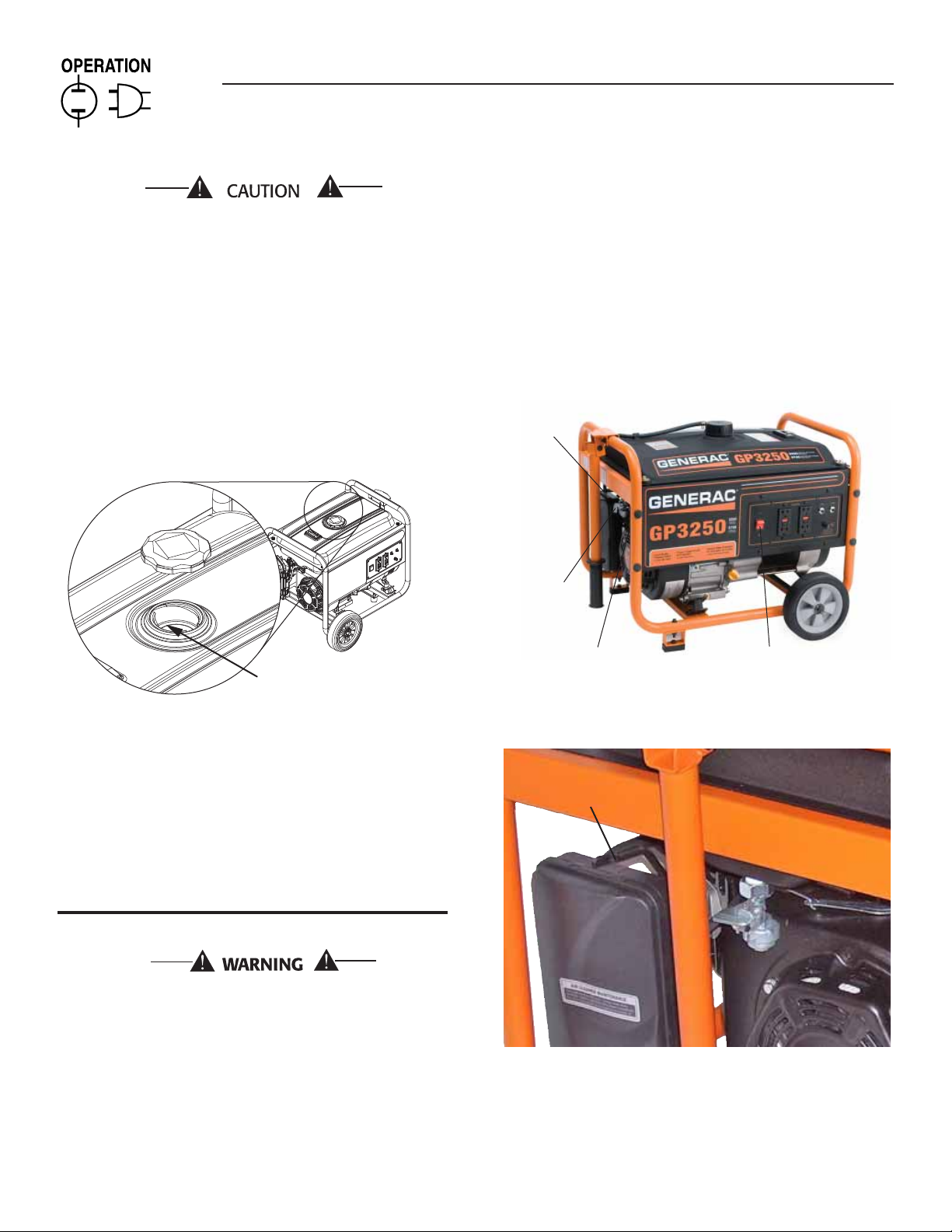
2.1 KNOW THE GENERATOR
Read the Owner’s Manual and Safety Rules before operating
this generator.
Compare the generator to Figures 3 through 6 to become
familiarized with the locations of various controls and adjustments.
Save this manual for future reference.
1. 120 Volt AC, 20 Amp, GFCI Receptacle – Supplies electrical
power for the operation of 120 Volt AC, 20 Amp, single-phase,
60 Hz electrical lighting, appliance, tool and motor loads.
2. Circuit Breakers (AC) – Each receptacle is provided with a
13.5A push-to-reset circuit breaker to protect the generator
against electrical overload.
3. Air Filter – Filters intake air as it is drawn into the engine.
4
Page 7

Section 2 – Operation
Portable Generator System
4. Choke Knob – Used when starting a cold engine.
5. Fuel Tank – Tank holds 4 U.S. gallons of fuel.
6. Grounding Lug – Ground the generator to an approved earth
ground here. See "Grounding the Generator" for details.
7. On/OFF Switch – Controls the operation of the generator.
8. Muffler – Quiets the engine.
9. Handle – Pivot and retract for storage.
10. Gas Cap – Fuel fill location.
11. Fuel Gauge – Shows fuel level in tank.
12. Oil Check/Fill – Check and fill oil here.
13. Recoil Starter – Use to start engine manually.
14. Fuel Shut Off – Valve between fuel tank and carburetor.
15. Oil Drain Plug – Used to drain engine oil.
16. Spark Arrestor – Reduces fire hazard by containing sparks.
17. Roll Over Valve – Passes fuel vapors to the carbon canister.
18. Carbon Canister – Absorbs fuel tank vapors.
19. Recovery Hose – Installed between items 17 & 18.
Figure 3 - Control Panel
7
21
15
Figure 5 - Generator Controls
7
16
8
12
6
Figure 6 - Generator Controls
6
Figure 4 - Generator Controls
17
19
18
19
5
Page 8

Section 2 – Operation
Portable Generator System
2.2 CORD SETS AND CONNECTION PLUGS
2.2.1 120 VAC, 20 AMP, DUPLEX RECEPTACLE
This is a 120 Volt outlet protected against overload by a 13.5 Amp
push-to-reset circuit breaker (Figure 6). 13.5 Amps of current may
be drawn from each socket, however, total power drawn must be
kept within data plate ratings. Use only high quality, well insulated,
3-wire grounded cord sets rated for 125 Volts at 20 Amps (or
greater).
2.3 HOW TO USE THE GENERATOR
If there are any problems operating the generator, please call the
generator helpline at 1-888-436-3722.
DANGER
Using a generator indoors WILL KILL YOU IN
MINUTES. Exhaust contains carbon monoxide, a
poison gas you cannot see or smell.
NEVER use in the home, or in partly enclosed
areas such as garages. ONLY use outdoors and
far from open windows, doors, vents, and in an
area that will not accumulate deadly exhaust
gas.
Using a generator indoors WILL KILL YOU IN MINUTES. Exhaust contains
carbon monoxide, a poison gas you cannot see or smell.
DANGER
Figure 7 - Grounding the Generator
2.3.2 CONNECTING ELECTRICAL LOADS
DO NOT connect 240 Volt loads to 120 Volt receptacles. DO NOT
connect 3-phase loads to the generator. DO NOT connect 50 Hz
loads to the generator.
Let engine stabilize and warm up for a few minutes after •
starting.
Plug in and turn on the desired 120 or 240 Volt AC, single •
phase, 60 Hz electrical loads.
Add up the rated watts (or amps) of all loads to be connected •
at one time. This total should not be greater than (a) the rated
wattage/amperage capacity of the generator or (b) circuit
breaker rating of the receptacle supplying the power. See "Don't
Overload the Generator".
NEVER use in the home or in partly enclosed areas such as garages.
ONLY use outdoors and far from open windows, doors and vents.
2.3.1 GROUNDING THE GENERATOR
The National Electrical Code requires that the frame and
external electrically conductive parts of this generator be
properly connected to an approved earth ground (Figure 7).
Local electrical codes may also require proper grounding of the
unit. For that purpose, connecting a No. 10 AWG (American Wire
Gauge) stranded copper wire to the grounding lug and to an
ear th-driven copper or brass grounding rod (electrode) provides
adequate protection against electrical shock. However, local codes
may vary widely. Consult with a local electrician for grounding
requirements in the area.
Proper grounding of the generator will help prevent electrical
shock in the event of a ground fault condition in the generator
or in connected electrical devices. Proper grounding also helps
dissipate static electricity, which often builds up in ungrounded
devices.
6
2.4 DON’T OVERLOAD THE GENERATOR
Overloading a generator in excess of its rated wattage capacity
can result in damage to the generator and to connected electrical
devices. Observe the following to prevent overloading the unit:
Add up the total wattage of all electrical devices to be connected •
at one time. This total should NOT be greater than the
generator's wattage capacity.
The rated wattage of lights can be taken from light bulbs. The •
rated wattage of tools, appliances and motors can usually be
found on a data label or decal affixed to the device.
If the appliance, tool or motor does not give wattage, multiply •
volts times ampere rating to determine watts (volts x amps =
watts).
Some electric motors, such as induction types, require about •
three times more watts of power for star ting than for running.
This surge of power lasts only a few seconds when star ting
such motors. Make sure to allow for high starting wattage when
selecting electrical devices to connect to the generator:
1. Figure the watts needed to start the largest motor.
2. Add to that figure the running watts of all other connected
loads.
The Wattage Reference Guide is provided to assist in determining
how many items the generator can operate at one time.
Page 9

10 W- 30
SA E 30
Sy nt he ti c 5W -3 0
Section 2 – Operation
Portable Generator System
NOTE:
All figures are approximate. See data label on appliance for
wattage requirements.
2.5 WATTAGE REFERENCE GUIDE
Device . . . . . . . . . . . . . . . . . . . . . . . . . . . . . . . . . . . Running Watts
*Air Conditioner (12,000 Btu). . . . . . . . . . . . . . . . . . . . . . . . . . 1700
*Air Conditioner (24,000 Btu). . . . . . . . . . . . . . . . . . . . . . . . . . 3800
*Air Conditioner (40,000 Btu). . . . . . . . . . . . . . . . . . . . . . . . . . 6000
Battery Charger (20 Amp). . . . . . . . . . . . . . . . . . . . . . . . . . . . . . 500
Belt Sander (3") . . . . . . . . . . . . . . . . . . . . . . . . . . . . . . . . . . . . 1000
Chain Saw . . . . . . . . . . . . . . . . . . . . . . . . . . . . . . . . . . . . . . . . 1200
Circular Saw (6-1/2") . . . . . . . . . . . . . . . . . . . . . . . . . . .800 to 1000
*Clothes Dryer (Electric) . . . . . . . . . . . . . . . . . . . . . . . . . . . . . 5750
*Clothes Dryer (Gas) . . . . . . . . . . . . . . . . . . . . . . . . . . . . . . . . . 700
*Clothes Washer . . . . . . . . . . . . . . . . . . . . . . . . . . . . . . . . . . . 1150
Coffee Maker . . . . . . . . . . . . . . . . . . . . . . . . . . . . . . . . . . . . . . 1750
*Compressor (1 HP). . . . . . . . . . . . . . . . . . . . . . . . . . . . . . . . . 2000
*Compressor (3/4 HP). . . . . . . . . . . . . . . . . . . . . . . . . . . . . . . 1800
*Compressor (1/2 HP). . . . . . . . . . . . . . . . . . . . . . . . . . . . . . . 1400
Curling Iron. . . . . . . . . . . . . . . . . . . . . . . . . . . . . . . . . . . . . . . . . 700
*Dehumidifier . . . . . . . . . . . . . . . . . . . . . . . . . . . . . . . . . . . . . . . 650
Disc Sander (9"). . . . . . . . . . . . . . . . . . . . . . . . . . . . . . . . . . . . 1200
Edge Trimmer. . . . . . . . . . . . . . . . . . . . . . . . . . . . . . . . . . . . . . . 500
Electric Blanket. . . . . . . . . . . . . . . . . . . . . . . . . . . . . . . . . . . . . . 400
Electric Nail Gun. . . . . . . . . . . . . . . . . . . . . . . . . . . . . . . . . . . . 1200
Electric Range (per element). . . . . . . . . . . . . . . . . . . . . . . . . . . 1500
Electric Skillet . . . . . . . . . . . . . . . . . . . . . . . . . . . . . . . . . . . . . . 1250
*Freezer . . . . . . .. . . . . . . . . . . . . . . . . . . . . . . . . . . . . . . . . . . ..700
*Furnace Fan (3/5 HP) . . . . . . . . . . . . . . . . . . . . . . . . . . . . . . . . 875
*Garage Door Opener. . . . . . . . . . . . . . . . . . . . . . . . . . . .500 to 750
Hair Dryer. . . . . . . . . . . . . . . . . . . . . . . . . . . . . . . . . . . . . . . . . 1200
Hand Drill . . . . . . . . . . . . . . . . . . . . . . . . . . . . . . . . . . . .250 to 1100
Hedge Trimmer. . . . . . . . . . . . . . . . . . . . . . . . . . . . . . . . . . . . . . 450
Impact Wrench . . . . . . . . . . . . . . . . . . . . . . . . . . . . . . . . . . . . . . 500
Iron. . . . . . . . . . . . . . . . . . . . . . . . . . . . . . . . . . . . . . . . . . . . . . 1200
*Jet Pump . . . . . . . . . . . . . . . . . . . . . . . . . . . . . . . . . . . . . . . . . 800
Lawn Mower. . . . . . . . . . . . . . . . . . . . . . . . . . . . . . . . . . . . . . . 1200
Light Bulb. . . . . . . . . . . . . . . . . . . . . . . . . . . . . . . . . . . . . . . . . . 100
Microwave Oven. . . . . . . . . . . . . . . . . . . . . . . . . . . . . . .700 to 1000
*Milk Cooler . . . . . . . . . . . . . . . . . . . . . . . . . . . . . . . . . . . . . . . 1100
Oil Burner on Furnace. . . . . . . . . . . . . . . . . . . . . . . . . . . . . . . . . 300
Oil Fired Space Heater (140,000 Btu) . . . . . . . . . . . . . . . . . . . . . 400
Oil Fired Space Heater (85,000 Btu) . . . . . . . . . . . . . . . . . . . . . . 225
Oil Fired Space Heater (30,000 Btu) . . . . . . . . . . . . . . . . . . . . . . 150
*Paint Sprayer, Airless (1/3 HP) . . . . . . . . . . . . . . . . . . . . . . . . . 600
Paint Sprayer, Airless (handheld). . . . . . . . . . . . . . . . . . . . . . . . . 150
Radio . . . . . . . . . . . . . . . . . . . . . . . . . . . . . . . . . . . . . . . . .50 to 200
*Refrigerator. . . . . . . . . . . . . . . . . . . . . . . . . . . . . . . . . . . . . . . . 700
Slow Cooker. . . . . . . . . . . . . . . . . . . . . . . . . . . . . . . . . . . . . . . . 200
*Submersible Pump (1-1/2 HP) . . . . . . . . . . . . . . . . . . . . . . . . 2800
*Submersible Pump (1 HP) . . . . . . . . . . . . . . . . . . . . . . . . . . . 2000
*Submersible Pump (1/2 HP). . . . . . . . . . . . . . . . . . . . . . . . . . 1500
*Sump Pump . . . . . . . . . . . . . . . . . . . . . . . . . . . . . . . . .800 to 1050
*Table Saw (10") . . . . . . . . . . . . . . . . . . . . . . . . . . . . .1750 to 2000
Television . . . . . . . . . . . . . . . . . . . . . . . . . . . . . . . . . . . . .200 to 500
Toaster. . . . . . . . . . . . . . . . . . . . . . . . . . . . . . . . . . . . .1000 to 1650
Weed Trimmer . . . . . . . . . . . . . . . . . . . . . . . . . . . . . . . . . . . . . . 500
* Allow 3 times the listed watts for star ting these devices.
2.6 BEFORE STARTING THE GENERATOR
Prior to operating the generator, engine oil and gasoline will need
to be added, as follows:
2.6.1 ADDING ENGINE OIL
All oil should meet minimum American Petroleum Institute (API)
Service Class SJ, SL or better. Use no special additives. Select
the oil's viscosity grade according to the expected operating
temperature (also see char t).
Above 40° F, use SAE 30•
Below 40° F and down to 10° F, use 10W-30•
Below 10° F, use synthetic 5W-30•
SAE 30
10W-30
Synthetic 5W-30
Any attempt to crank or start the engine before
it has been properly serviced with the
recommended oil may result in an engine
failure.
Place generator on a level surface.•
Clean area around oil fill and remove oil fill cap and dipstick.•
Wipe dipstick clean.•
Slowly fill engine with oil through the oil fill opening until it •
reaches the full mark on the dipstick. Stop filling occasionally
to check oil level. Be careful not to over fill.
Install oil fill cap and finger tighten securely.•
Check engine oil level before star ting each time thereaf ter.•
2.6.2 ADDING GASOLINE
DANGER
Never fill fuel tank indoors. Never fill fuel tank
when engine is running or hot. Allow engine
to cool entirely before filling fuel tank. Avoid
spilling gasoline on HOT engine. DO NOT light
a cigarette or smoke when filling the fuel tank.
Gasoline is highly FLAMMABLE and its vapors
are EXPLOSIVE.
7
Page 10
Section 2 – Operation
Portable Generator System
Do not overfill the fuel tank. Always leave room
for fuel expansion. If the fuel tank is overfilled,
fuel can overflow onto a HOT engine and cause
FIRE or EXPLOSION.
Use regular UNLEADED gasoline with the generator engine. Do •
not use any gasoline with more than 10% added Ethanol, and
never use E85 gasoline. Do not mix oil with gasoline.
Clean area around fuel fill cap, remove cap.•
Slowly add unleaded regular gasoline to fuel tank. Fill to bottom •
of screen filter. Be careful not to overfill (Figure 8).
Install fuel cap and wipe up any spilled gasoline. •
Figure 8 - Fuel Tank
To start engine, fir mly grasp the recoil handle and pull slowly •
until increased resistance is felt. Pull rapidly up and away.
When engine star ts, move choke lever to • 1/2-CHOKE position
until engine runs smoothly and then fully into RUN position. If
engine falters, move choke back out to 1/2-CHOKE position
until engine runs smoothly and then to RUN position.
NOTE:
If engine fires, but does not continue to run, move choke lever to
the START position and repeat starting instructions.
Figure 9 - Fuel Shut-off Valve
CHOKE
DO NOT FILL ABOVE THE LIP!
IMPORTANT: It is important to prevent gum deposits from forming
in fuel system parts such as the carburetor, fuel hose or tank
during storage. Alcohol-blended fuels (called gasohol, ethanol
or methanol) can attract moisture, which leads to separation and
formation of acids during storage. Acidic gas can damage the fuel
system of an engine while in storage. To avoid engine problems,
the fuel system should be emptied before storage of 30 days or
longer. See the "Storage" section. Never use engine or carburetor
cleaner products in the fuel tank as permanent damage may
occur.
2.7 TO START THE ENGINE
Never start or stop engine with electrical
devices plugged into the receptacles AND
devices turned on.
Unplug all electrical loads from the unit's receptacles before •
star ting the engine.
Make sure the unit is in a level position.•
T• urn the Fuel Shut-off Valve to the "ON" position (Figure 9).
Turn engine ON/OFF switch to • ON position (Figure 9).
Move engine CHOKE lever to the • START position (Figure 10).
8
FUEL
LEVER
RECOIL
HANDLE
ON/OFF SWITCH
Figure 10 - Choke Position
Choke Position
IMPORTANT: Do not overload the generator. Also, do not
overload individual panel receptacles. These outlets are protected
against overload with push-to-reset-type circuit breakers. If
amperage rating of any circuit breaker is exceeded, that breaker
opens and electrical output to that receptacle is lost. Read “Don’t
Overload the Generator” carefully.
Page 11

Section 3 — Maintenance
Portable Generator System
2.8 STOPPING THE ENGINE
Shut off all loads, then unplug the electrical loads from generator •
panel receptacles. Never star t or stop the engine with electrical
devices plugged in and turned on.
Let engine run at no-load for several minutes to stabilize the •
internal temperatures of engine and generator.
Move ON/OFF switch to • OFF position.
Close fuel valve.•
2.9 LOW OIL LEVEL SHUTDOWN SYSTEM
The engine is equipped with a low oil level sensor that shuts down
the engine automatically when the oil level drops below a specified
level. If the engine shuts down by itself and the fuel tank has
enough gasoline, check engine oil level.
2.9.1 SENSING LOW OIL LEVEL
If the system senses a low oil level during operation, the engine
shuts down. The engine will not run until the oil has been refilled
to the proper level.
3.1 MAINTENANCE SCHEDULE
Follow the calendar intervals. More frequent service is required
when operating in adverse conditions noted below.
Check Oil Level At Each Use
Change Oil + *Every Season
Check Valve Clearance ***Every Season
Service Air Filter **Every Season
Replace Spark Plug Every Season
+ Change oil after first 20 hours of operation, then ever y season.
* Change oil every month when operating under heavy load or in high
temperatures.
** Clean more of ten under dir ty or dusty operating conditions. Replace air filter
parts if they cannot be adequately cleaned.
*** Check valve clearance and adjust if necessary after first 50 hours of
operation and every 100 hours thereafter.
3.2 PRODUCT SPECIFICATIONS
3.2.2 ENGINE SPECIFICATIONS
Displacement ..............................................................................208 cc
Spark Plug Type ................... F6TC, NGK BPR4ES or Champion RN14YC
Spark Plug Gap ............................. 0.028-0.031 inch or (0.70-0.80 mm)
Gasoline Capacity .............................................15.14 L (4 U.S. gallons)
Oil Type..................See Chart in "Before Starting the Generator" Section
Oil Capacity ...............................................................0.6 L (0.634 Qts.)
Run Time ........................................................... 12.5 Hours at 1/2 Load
Class II Emission Certified*
* The engine manufacturer must warrant the emission control system
for a period of two years. This warranty coverage is in addition to
the warranty provided by Generac, and may cover the engine even if
Generac’s warranty does not.
3.3 GENERAL RECOMMENDATIONS
The warranty of the generator does not cover items that have been
subjected to operator abuse or negligence. To receive full value
from the warranty, the operator must maintain the generator as
instructed in this manual.
Some adjustments will need to be made periodically to properly
maintain the generator.
All adjustments in the Maintenance section of this manual should
be made at least once each season. Follow the requirements in the
"Maintenance Schedule".
NOTE:
Once a year replace the spark plug and replace the air filter.
A new spark plug and clean air filter assure proper fuel-air
mixture and help the engine run better and last longer.
3.3.1 GENERATOR MAINTENANCE
Generator maintenance consists of keeping the unit clean and dry.
Operate and store the unit in a clean dry environment where it will
not be exposed to excessive dust, dir t, moisture or any corrosive
vapors. Cooling air slots in the generator must not become clogged
with snow, leaves, or any other foreign material.
Check the cleanliness of the generator frequently and clean when
dust, dir t, oil, moisture or other foreign substances are visible on
its exterior surface.
3.2.1 GENERATOR SPECIFICATIONS
Rated. Power ........................................................................3.25 kW**
Surge Power ............................................................................. 3.75 kW
Rated AC Voltage .............................................................................120
Rated Current .......................................................................27 Amps**
Rated Frequency .................................................... 60 Hz @ 3600 RPM
Phase ................................................................................Single Phase
** Maximum wattage is subject to, and limited by, such factors as fuel Btu
content, ambient temperature, altitude, engine condition, etc.. Maximum
power decreases about 3.5% for each 1,000 feet above sea level; and will
also decrease about 1% for each 6° C (10° F) above 16° C (60° F) ambient
temperature.
Never insert any object or tool through the air
cooling slots, even if the engine is not running.
NOTE:
DO NOT use a garden hose to clean generator. Water can enter
the engine fuel system and cause problems. In addition, if water
enters the generator through cooling air slots, some water will
be retained in voids and crevices of the rotor and stator winding
insulation. Water and dirt buildup on the generator internal
windings will eventually decrease the insulation resistance of
these windings.
9
Page 12

Section 3 — Maintenance
Portable Generator System
3.3.2 TO CLEAN THE GENERATOR
Use a damp cloth to wipe exterior surfaces clean.•
A soft, bristle br ush may be used to loosen caked on dir t, oil, •
etc.
A vacuum cleaner may be used to pick up loose dirt and •
debris.
Low pressure air (not to exceed 25 psi) may be used to •
blow away dirt. Inspect cooling air slots and openings
on the generator. These openings must be kept clean and
unobstructed.
3.3.3 ENGINE MAINTENANCE
DANGER
When working on the generator, always
disconnect spark plug wire from spark plug and
keep wire away from spark plug.
3.3.4 CHECKING OIL LEVEL
See the “Before Star ting the Generator” section for information on
checking the oil level. The oil level should be checked before each
use, or at least every eight hours of operation. Keep the oil level
maintained (Figure 11).
Use the following instructions to change the oil while the engine
is still warm:
Clean area around oil drain plug.•
Remove oil drain plug from engine and oil fill plug to drain oil •
completely into a suitable container.
When oil has completely drained, install oil drain plug and •
tighten securely.
Fill engine with recommended oil. (See “Before Starting the •
Generator” for oil recommendations).
Wipe up any spilled oil.•
Dispose of used oil at a proper collection center.•
3.3.6 REPLACING THE SPARK PLUG
Use spark plug F6TC, NGK BPR4ES or Champioin RN14YC.
Replace the plug once each year. This will help the engine star t
easier and run better.
1. Stop the engine and pull the spark plug wire off of the spark
plug.
2. Clean the area around the spark plug and remove it from the
cylinder head.
3. Set the spark plug's gap to 0.70-0.80 mm (0.028-0.031 in.).
Install the correctly gapped spark plug into the cylinder head
and torque to 15 ft/lbs. (Figure 12).
Figure 11 - Oil Drain, Check & Fill
Oil Drain
Oil Check & Fill
3.3.5 CHANGING THE OIL
Change the oil after the first eight hours of operation, then every 20
hours thereafter. If running this unit under dirty or dusty conditions,
or in extremely hot weather, change the oil more often.
Hot oil may cause burns. Allow engine to cool
before draining oil. Avoid prolonged or repeated
skin exposure with used oil. Thoroughly wash
exposed areas with soap.
10
Figure 12 - Spark Plug Gap
3.3.7 SPARK ARRESTOR
1. Shut off generator and allow the engine and muffler to cool
down completely before servicing spark arrestor (located on
the back of the muffler).
2. Remove the clamp and spark arrestor screen.
3. Clean the spark arrestor screen with a small wire brush.
4. Replace the spark arrestor if it is damaged.
5. Installation of the spark arrestor screen is the reverse of the
removal.
3.4 SERVICE AIR FILTER
The engine will not run properly and may be damaged if using a
dir ty air filter. Clean the air filter once a year (Figure 13). Clean or
replace more often if operating under dusty conditions.
Remove air filter cover.•
Wash in soapy water. Squeeze filter dry in clean cloth (DO NOT •
TWIST).
Clean air filter cover before re-installing it.•
Page 13

Section 3 — Maintenance
Portable Generator System
NOTE:
To order a new air filter, please contact the nearest authorized
service center at 1-888-436-3722.
Figure 13 - Air Filter
Air Cleaner Cover
Air Filter
3.5 VALVE CLEARANCE
Intake — 0.10 ± 0.02mm (cold), (0.003" ± 0.005" inches)•
Exhaust — 0.15 ± 0.02mm (cold) (0.005" ± 0.007" inches)•
After the first 50 hours of operation, check the valve clearance
in the engine and adjust if necessary.
Important: If feeling uncomfortable about doing this procedure or
the proper tools are not available, please take the generator to the
nearest service center to have the valve clearance adjusted. This is
a very important step to ensure longest life for the engine.
3.6 GENERAL
The generator should be star ted at least once every seven days
and be allowed to run at least 30 minutes. If this cannot be done
and the unit must be stored for more than 30 days, use the
following information as a guide to prepare it for storage.
DANGER
NEVER store engine with fuel in tank indoors
or in enclosed, poorly ventilated areas where
fumes may reach an open flame, spark or pilot
light as on a furnace, water heater, clothes dryer
or other gas appliance.
3.7 LONG TERM STORAGE
It is impor tant to prevent gum deposits from forming in essential
fuel system par ts such as the carburetor, fuel hose or tank during
storage. Also, experience indicates that alcohol-blended fuels
(called gasohol, ethanol or methanol) can attract moisture, which
leads to separation and formation of acids during storage. Acidic
gas can damage the fuel system of an engine while in storage.
To avoid engine problems, the fuel system should be emptied
before storage of 30 days or longer, as follows:
Remove all gasoline from the fuel tank.•
DANGER
Drain fuel into approved container outdoors,
away from open flame. Be sure engine is cool.
Do not smoke.
Star t and r un engine until engine stops from lack of fuel.•
While engine is still warm, drain oil from crankcase. Refill with •
recommended grade.
Remove spark plugs and pour about 1/2 ounce (15 ml) of •
engine oil into the cylinders. Cover spark plug hole with rag.
Pull the recoil starter a couple times to lubricate the piston rings
and cylinder bore.
Avoid spray from spark plug holes when
cranking engine.
Install and tighten spark plugs. Do not connect spark plug •
wires.
Clean the generator outer surfaces. Check that cooling air slots •
and openings on generator are open and unobstructed.
Store the unit in a clean, dry place.•
3.8 OTHER STORAGE TIPS
Do not store gasoline from one season to another.•
Replace the gasoline can if it starts to r ust. Rust and/or dir t in •
the gasoline will cause problems with the carburetor and fuel
system.
If possible, store the unit indoors and cover it to give protection •
from dust and dir t. BE SURE TO EMPTY THE FUEL TANK.
If it is not practical to empty the fuel tank and the unit is to be •
stored for some time, use a commercially available fuel stabilizer
added to the gasoline to increase the life of the gasoline.
Cover the unit with a suitable protective cover that does not •
retain moisture.
DANGER
NEVER cover the generator while engine and
exhaust areas are warm.
11
Page 14

Section 4 — Troubleshooting
Portable Generator System
4.1 TROUBLESHOOTING GUIDE
PROBLEM CAUSE CORRECTION
Engine is running, but no AC output
is available.
1. Circuit breaker is open.
2. Poor connection or defective cord set.
3. Connected device is bad.
4. Fault in generator.
1. Reset circuit breaker.
2. Check and repair.
3. Connect another device that is in good condition.
4. Contact Authorized Service Facility.
Engine runs good but bogs down
when loads are connected.
Engine will not start; or starts and
runs rough.
Engine shuts down during
operation.
Engine lacks power. 1. Load is too high.
1. Short circuit in a connected load.
2. Generator is overloaded.
3. Engine speed is too slow.
4. Shorted generator circuit.
1. Dirty air filter.
2. Out of gasoline.
3. Stale gasoline.
4. Spark plug wire not connected to spark plug.
5. Bad spark plug.
6. Water in gasoline.
7. Over-choking.
8. Low oil level.
9. Excessive rich fuel mixture.
10. Intake valve stuck open or closed.
11. Engine has lost compression.
1. Out of gasoline.
2. Low oil level.
3. Fault in engine.
2. Dirty air filter.
3. Engine needs to be serviced.
1. Disconnect shorted electrical load.
2. See “Don’t Overload the Generator” .
3. Contact Authorized Service Facility.
4. Contact Authorized Service Facility.
1. Clean or replace air filter.
2. Fill fuel tank.
3. Drain fuel tank and fill with fresh fuel.
4. Connect wire to spark plug.
5. Replace spark plug.
6. Drain fuel tank; fill with fresh fuel.
7. Put choke knob to No Choke position.
8. Fill crankcase to proper level.
9. Contact Authorized Service Facility.
10. Contact Authorized Service Facility.
11. Contact Authorized Service Facility.
1. Fill fuel tank.
2. Fill crankcase to proper level.
3. Contact Authorized Service Facility.
1. See “Don’t Overload the Generator”.
2. Replace air filter.
3. Contact Authorized Service Facility.
Engine “hunts” or falters. 1. Choke is opened too soon.
2. Carburetor is running too rich or too lean.
12
1. Move choke to halfway position until engine runs
smoothly.
2. Contact Authorized Service Facility.
Page 15

Section 5 — Notes
13
Page 16

Section 6 — Warranty
Portable Generator System
FEDERAL EMISSION CONTROL WARRANTY STATEMENT
YOUR WARRANTY RIGHTS AND OBLIGATIONS
The United States Environmental Protection Agency (EPA) and Generac Power Systems, Inc. (Generac) are pleased to explain the
Emission Control System warranty on your new 2008 and later equipment. New equipment that use small spark-ignited engines
must be designed, built, and equipped to meet stringent anti-smog standards for the federal government. Generac will warrant
the emission control system on your generator for the period of time listed below provided there has been no abuse, neglect,
unapproved modification or improper maintenance of your equipment.
Your emission control system may include parts such as the: carburetor, ignition system, fuel system, catalytic converter, and other
associated emission-related components (if equipped).
MANUFACTURER’S WARRANTY COVERAGE:
This emission control system is warranted for two years. If, during such warranty period, any emission-related part on your
equipment is found to be defective in materials or workmanship, repairs or replacement will be performed by a Generac
Authorized Warranty Service Dealer.
OWNER'S WARRANTY RESPONSIBILITIES:
As the generator owner, you are responsible for the completion of all required maintenance as listed in your factory supplied
Owner's Manual. For warranty purposes, Generac recommends that you retain all receipts covering maintenance on your
generator, but Generac cannot deny warranty solely due to the lack of receipts.
As the generator owner, you should be aware that Generac may deny any and/or all warranty coverage or responsibility if your
generator, or a part/component thereof, has failed due to abuse, neglect, improper maintenance or unapproved modifications, or
the use of counterfeit and/or "grey market" parts not made, supplied or approved by Generac.
You are responsible for contacting a Generac Authorized Warranty Dealer as soon as a problem occurs. The warranty
repairs should be completed in a reasonable amount of time, not to exceed 30 days.
Warranty service can be arranged by contacting either your selling dealer or a Generac Authorized Warranty Service Dealer. To
locate the Generac Authorized Warranty Service Dealer nearest you, call our toll free number:
1-800-333-1322
IMPORTANT NOTE: This warranty statement explains your rights and obligations under the Emission Control System Warranty
(ECS Warranty), which is provided to you by Generac pursuant to federal law. See also the "Generac Limited Warranties for
Generac Power Systems, Inc.," which is enclosed herewith on a separate sheet, also provided to you by Generac. Note that this
warranty shall not apply to any incidental, consequential or indirect damages caused by defects in materials or workmanship or
any delay in repair or replacement of the defective part(s). This warranty is in place of all other warranties, expressed or implied.
Specifically, Generac makes no other warranties as to the merchantability or fitness for a particular purpose. Some states do not
allow limitations on how long an implied warranty lasts, so the above limitation may not apply to you.
The ECS Warranty applies only to the emission control system of your new equipment. If there is any conflict in terms between the
ECS Warranty and the Generac Warranty, the Generac Warranty shall apply. Both the ECS Warranty and the Generac Warranty
describe important rights and obligations with respect to your new engine.
Warranty service can be performed only by a Generac Authorized Warranty Service Facility. When requesting warranty service,
evidence must be presented showing the date of the sale to the original purchaser/owner.
If you have any questions regarding your warranty rights and responsibilities, you should contact Generac at the following
address:
ATTENTION WARRANTY DEPARTMENT
GENERAC POWER SYSTEMS, INC.
P.O. BOX 297 • WHITEWATER, WI 53190
Part 1
14
Part No. 0H1913 Rev. A 08/09
Page 17

Section 6 — Warranty
Portable Generator System
EMISSION CONTROL SYSTEM WARRANTY
Emission Control System Warranty (ECS warranty) for equipment using small spark-ignited engines:
(a) Applicability: This warranty shall apply to equipment that uses small off-road engines. The ECS Warranty period shall begin
on the date the new equipment is purchased by/delivered to its original, end-use purchaser/owner and shall continue for 24
consecutive months thereafter.
(b) General Emissions Warranty Coverage: Generac warrants to the original, end-use purchaser/owner of the new engine or
equipment and to each subsequent purchaser/owner that the ECS when installed was:
(1) Designed, built and equipped so as to conform with all applicable regulations; and
(2) Free from defects in materials and workmanship which cause the failure of a warranted part at any time during the ECS
Warranty Period.
(c) The warranty on emissions-related parts will be interpreted as follows:
(1) Any warranted part that is not scheduled for replacement as required maintenance in the Owner's Manual shall be
warranted for the ECS Warranty Period. If any such part fails during the ECS Warranty Period, it shall be repaired or
replaced by Generac according to Subsection (4) below. Any such part repaired or replaced under the ECS Warranty shall
be warranted for the remainder of the ECS Warranty Period.
(2) Any warranted part that is scheduled only for regular inspection as specified in the Owner's Manual shall be warranted
for the ECS Warranty Period. A statement in the Owner’s Manual to the effect of "repair or replace as necessary" shall not
reduce the ECS Warranty Period. Any such part repaired or replaced under the ECS Warranty shall be warranted for the
remainder of the ECS Warranty Period.
(3) Any warranted part that is scheduled for replacement as required maintenance in the Owner's Manual shall be warranted
for the period of time prior to first scheduled replacement point for that part. If the part fails prior to the first scheduled
replacement, the part shall be repaired or replaced by Generac according to Subsection (4) below. Any such emissionsrelated part repaired or replaced under the ECS warranty shall be warranted for the remainder of the period prior to the
first scheduled replacement point for that part.
(4) Repair or replacement of any warranted, emissions-related part under this ECS Warranty shall be performed at no charge
to the owner at a Generac Authorized Warranty Service Facility.
(5) Notwithstanding the provisions of subsection (4) above, warranty services or repairs must be provided at Generac
Authorized Service Facilities.
(6) When the engine is inspected by a Generac Authorized Warranty Service Facility, the purchaser/owner shall not be held
responsible for diagnostic costs if the repair is deemed warrantable.
(7) Throughout the ECS Warranty Period, Generac shall maintain a supply of warranted emission-related parts sufficient to
meet the expected demand for such parts.
(8) Any Generac authorized and approved emission-related replacement parts may be used in the performance of any ECS
warranty maintenance or repairs and will be provided without charge to the purchaser/owner. Such use shall not reduce
Generac ECS Warranty obligations.
(9) Unapproved, add-on, modified, counterfeit and/or "grey market" parts may not be used to modify or repair a Generac
engine. Such use voids this ECS Warranty and shall be sufficient grounds for disallowing an ECS Warranty claim. Generac
shall not be held liable hereunder for failures of any warranted parts of Generac equipment caused by the use of such an
unapproved, add-on, modified, counterfeit and/or "grey market" part.
EMISSION RELATED PARTS MAY INCLUDE THE FOLLOWING (IF EQUIPPED):
1) FUEL SYSTEM
A. FUEL TANK
B. FUEL CAP
C. FUEL LINE
D FUEL LINE FIT TINGS
E. CLAMPS*
F. PRESSURE RELIEF VALVES*
2) EVAPORATIVE CONTROL SYSTEM
A. CARBON CANISTER
B. CANISTER NOUNTING BRACKET
C. CARBURETOR PURGE PORT
D. CONTROL VALVES*
E. VAPOR HOSES
F. PURGE VALVES
G. LIQUID/VAPOR SEPARATOR
H. VACUUM CONTROL DIAPHRAGMS*
Part 2
3) FUEL METERING SYSTEM
A. CARBURETOR AND INTERNAL PARTS
B. PRESSURE REGULATOR
4) AIR INDUCTION SYSTEM
A. INTAKE MANIFOLD
B. AIR FILTER
5) IGNITION SYSTEM
A. SPARK PLUGS
B. IGNITION COILS/MODULE
6) AIR INJECTION SYSTEM
A. PULSE AIR VALVE
7) EXHAUST SYSTEM
A. CATALYST
B. THERMAL REACTOR
C. EXHAUST MANIFOLD
*NOTE: As they relate to the Emission Control System.
Part No. 0H1913 Rev. A ??/??
15
Page 18

Section 6 — Warranty
Portable Generator System
GENERAC POWER SYSTEMS “TWO YEAR” LIMITED WARRANTY FOR
GP SERIES PORTABLE GENERATORS
For a period of two years from the date of original sale, Generac Power Systems, Inc. (Generac) warrants its GP Series generators will be free from defects in
materials and workmanship for the items and period set forth below. Generac will, at its option, repair or replace any par t which, upon examination, inspection and
testing by Generac or a Generac Authorized Warranty Service Dealer, is found to be defective. Any equipment that the purchaser/owner claims to be defective must
be returned to and examined by the nearest Generac Authorized Warranty Service Dealer. All transportation costs under the warranty, including return to the factory,
are to be borne and prepaid by the purchaser/owner. This warranty applies only to Generac GP Series portable generators and is not transferable from original
purchaser. Save your proof-of-purchase receipt. If you do not provide proof of the initial purchase date, the manufacturer’s shipping date of the product will be used
to determine the warranty period.
WARRANTY SCHEDULE
Consumer applications are warranted for two (2) years. Commercial and Rental applications are warranted for one (1) year or 1000 hours maximum, whichever comes first.
CONSUMER APPLICATION
YEARS ONE and TWO - 100% (one hundred percent) coverage on Labor and Part(s) listed (proof of purchase and maintenance is required):
• Engine- All Components
• Alternator- All Components
COMMERCIAL/RENTAL APPLICATION
YEAR ONE – 100% (one hundred percent) coverage on Labor and Part(s) listed (proof of purchase and maintenance is required):
• Engine- All Components
• Alternator- All Components
NOTE: For the purpose of this warranty “consumer use” means personal residential household or recreational use by original purchaser. This warranty does not apply to units
used for Prime Power in place of utility where utility power service is present or where utility power service does not normally exist. Once a generator has experienced
commercial or rental use, it shall thereafter be considered a non-consumer use generator for the purpose of this warranty.
All warranty expense allowances are subject to the conditions defined in Generac’s Warranty Policies, Procedures and Flat Rate Manual.
THIS WARRANTY SHALL NOT APPLY TO THE FOLLOWING:
Generac built portable generators built prior to May 2008.•
Generac portable generators that utilize non-Generac replacement parts.•
Costs of normal maintenance and adjustments.•
Failures caused by any contaminated fuels, oils or lack of proper oil levels.•
Repairs or diagnostics performed by individuals other than Guardian/Generac authorized dealers not authorized in writing by Generac Power Systems.•
Failures due, but not limited, to normal wear and tear, accident, misuse, abuse, negligence or improper use. As with all mechanical devices, the Generac engines need periodic •
part(s) service and replacement to perform as designed. This warranty will not cover repair when normal use has exhausted the life of a part(s) or engine.
Failures caused by any external cause or act of God, such as collision, theft, vandalism, riot or wars, nuclear holocaust, fire, freezing, lightning, earth-quake, windstorm, hail, •
volcanic eruption, water or flood, tornado or hurricane.
Damage related to rodent and/or insect infestation.•
Products that are modified or altered in a manner not authorized by Generac in writing.•
Any incidental, consequential or indirect damages caused by defects in materials or workmanship, or any delay in repair or replacement of the defective part(s).•
Failure due to misapplication.•
Telephone, cellular phone, facsimile, internet access or other communication expenses.•
Living or travel expenses of person(s) performing service, except as specifically included within the terms of a specific unit warranty period.•
Expenses related to “customer instruction” or troubleshooting where no manufacturing defect is found.•
Rental equipment used while warranty repairs are being performed.•
Overnight freight or special shipping costs for replacement part(s).•
Overtime, holiday or emergency labor.•
Starting batteries, fuses, light bulbs and engine fluids.•
THIS WARRANTY IS IN PLACE OF ALL OTHER WARRANTIES, EXPRESSED OR IMPLIED. SPECIFICALLY, GENERAC MAKES NO OTHER WARRANTIES AS TO THE
MERCHANTABILITY OR FITNESS FOR A PARTICULAR PURPOSE. Some states do not allow limitations on how long an implied warranty lasts, so the above limitation may not
apply to you. GENERAC’S ONLY LIABILITY SHALL BE THE REPAIR OR REPLACEMENT OF PART(S) AS STATED ABOVE. IN NO EVENT SHALL GENERAC BE LIABLE FOR ANY
INCIDENTAL OR CONSEQUENTIAL DAMAGES, EVEN IF SUCH DAMAGES ARE A DIRECT RESULT OF GENERAC’S NEGLIGENCE. Some states do not allow the exclusion or
limitation of incidental or consequential damages, so the above limitation may not apply to you. This warranty gives you specific legal rights. You also have other rights from
state to state.
GENERAC POWER SYSTEMS, INC.
P.O. BOX 8 • Waukesha, WI 53187
Ph: (888) GENERAC (436-3722) • Fax: (262) 544-4851
To locate the nearest Authorized Dealer visit our website www.generac.com
Part No. 0H3172 Revision A (05/15/09) Printed in China
Manual Part No. 0H2379 Rev A (08/04/09) Printed in China
Page 19

Serie GP Generador portátil
2 AÑOS
GARANTÍA
LIMITADA
MODELO: 005789-0
Manual del propietario
• SEGURIDAD
• MONTAJE
• OPERACIÓN
• RESOLUCIÓN
DE PROBLEMAS
• GARANTÍA
ASISTENCIA DE CONCESIONARIOS
AUTORIZADOS:
www.generac.com
o
1-888-GENERAC
17
Page 20

Índice
Sistema de generador portátil
Introducción ..........................................................19
Lea este manual completamente .......................... 19
Reglas de seguridad .............................................20
Índice de estándares ....................................................21
Sección 1 – Información general ..........................22
1.1 Desembalaje ................................................................22
1.1.1 Caja de accesorios ..........................................22
1.2 Montaje .......................................................................22
1.2.1 Montaje del juego de accesorios ......................22
Sección 2 – Operación .......................................... 22
2.1 Familiarícese con su generador ....................................22
2.2 Juegos de cables eléctricos y conectores.....................24
2.2.1 Receptáculo dúplex de 120 V de CA, 20 A .......24
Sección 3 – Mantenimiento ..................................27
3.1 Programa de mantenimiento ........................................27
3.2 Especificaciones del producto ...................................... 27
3.2.1 Especificaciones del generador ........................27
3.2.2 Especificaciones del motor ..............................27
3.3 Recomendaciones generales ........................................27
3.3.1 Mantenimiento del generador ........................... 27
3.3.2 Limpieza del generador ....................................28
3.3.3 Mantenimiento del motor .................................28
3.3.4 Medición del nivel de aceite .............................28
3.3.5 Cambio del aceite ............................................28
3.3.6 Reemplazo de la bujía ......................................28
3.3.7 Malla amor tiguadora de chispas ......................28
3.4 Mantenimiento del filtro de aire ....................................29
3.5 Holgura de la válvula .................................................... 29
3.6 General .......................................................................29
2.3 Cómo usar el generador ...............................................24
2.3.1 Conexión a tierra del generador ........................24
2.3.2 Conexión de las cargas eléctricas ....................24
2.4 No sobrecargue el generador........................................24
2.5 Guía de referencia del vataje ......................................... 25
2.6 Antes de poner en marcha el generador .......................25
2.6.1 Adición de aceite del motor ..............................25
2.6.2 Adición de gasolina..........................................25
2.7 Arranque del motor ......................................................26
2.8 Detención del motor .....................................................27
2.9 Sistema de apagado por bajo nivel de aceite ................27
2.9.1 Detección de bajo nivel de aceite .....................27
3.7 Almacenamiento a largo plazo ......................................29
3.8 Otras sugerencias para el almacenamiento ...................29
Sección 4 – Localización y resolución
de problemas ...............................................30
4.1 Guía de localización y resolución de problemas ............30
Sección 5 – Notas ................................................. 31
Sección 6 – Garantía ............................................32
18
Page 21

INTRODUCCIÓN
PELIGRO
ADVERTENCIA
CUIDADO
PELIGRO
ADVERTENCIA
Gracias por comprar este modelo de Generac Power Systems, Inc.
Este modelo es un generador impulsado por motor, refrigerado por aire,
compacto y de alto rendimiento diseñado para proporcionar energía
eléctrica para operar cargas eléctricas donde no haya servicio público de
electricidad o en reemplazo de la red eléctrica en caso de apagones.
LEA ESTE MANUAL COMPLETAMENTE
Si alguna parte de este manual no se entiende bien, póngase en
contacto con el concesionario autorizado más cercano para conocer los
procedimientos de arranque, operación y servicio.
A lo largo de esta publicación, y en lo que respecta a las etiquetas
y calcomanías fijadas en el generador, los bloques de PELIGRO,
ADVERTENCIA, CUIDADO Y NOTA se usan para alertar al personal sobre
instrucciones especiales sobre una operación en particular que puede ser
peligrosa si se ejecuta en forma incorrecta o sin cuidado. Obsérvelas con
cuidado. Sus definiciones son como sigue:
Luego de este encabezado, lea las instrucciones que,
si no se siguen estrictamente, traerán como resultado
daños personales serios, incluyendo la muerte y/o
daños a la propiedad.
Asimismo recomendamos con igual firmeza el instruir a otros usuarios
para arrancar y operar apropiadamente la unidad. Esto los prepara si
necesitan operar el equipo en alguna emergencia.
Si usa un generador en interiores, MORIRÁ EN
POCOS MINUTOS. El escape contiene monóxido de
carbono, un gas venenoso que no se ve ni huele a
nada.
NUNCA lo use en el hogar ni en áreas parcialmente
encerradas como los garajes. Úselo SÓLO en
exteriores y lejos de ventanas abiertas, puertas,
ductos de ventilación y en áreas que no acumularán
el mortal gas del escape.
DANGER
Using a generator indoors WILL KILL YOU IN MINUTES. Exhaust contains
carbon monoxide, a poison gas you cannot see or smell.
NEVER use in the home or in partly enclosed areas such as garages.
ONLY use outdoors and far from open windows, doors and vents.
Luego de este encabezado, lea las instrucciones que,
si no se siguen estrictamente, pueden traer como
resultado daños personales serios y/o daños a la
propiedad.
Luego de este encabezado, lea las instrucciones que,
si no se siguen estrictamente, podrían traer como
resultado daños al equipo y/o a la propiedad.
NOTA:
Luego de este encabezado, lea las explicaciones que requieren
especial énfasis.
Estas advertencias de seguridad no pueden eliminar los peligros que
indican. El sentido común y un estricto cumplimiento de las instrucciones
especiales cuando se realiza un servicio son esenciales para evitar
accidentes.
Cuatro símbolos de seguridad usados comúnmente acompañan los
bloques de PELIGRO, ADVERTENCIA y CUIDADO. El tipo de información
que cada uno indica es como sigue:
Este símbolo señala importante información de
seguridad que, si no se sigue, puede poner en
peligro la seguridad personal y/o las propiedades de
otros.
Este símbolo indica un peligro potencial de
explosión.
Este símbolo indica un peligro potencial de incendio.
Este símbolo indica un peligro potencial de descarga
eléctrica.
El operador es responsable del uso apropiado y seguro de este equipo.
Recomendamos encarecidamente que el operador lea este manual y
entienda completamente todas las instrucciones antes de usar este
equipo.
Siempre desconecte el cable de la bujía y coloque
el cable donde no pueda tener contacto con la bujía
para evitar un arranque accidental al configurar,
transportar, ajustar o hacer reparaciones en el
generador.
El generador produce un voltaje peligrosamente alto que puede causar •
descargas eléctricas extremadamente peligrosas. Evite el contacto
con cables pelados, terminales, etc. Nunca permita que personas no
calificadas operen o den servicio al generador.
Nunca manipule ningun cable eléctrico ni dispositivo mientras esté •
de pie sobre agua, con los pies descalzos o con las manos o pies
húmedos. Puede ocasionarse una descarga eléctrica peligrosa.
El Código Eléctrico Nacional requiere que el marco y las partes •
externas que son conductores eléctricos estén conectadas en forma
apropiada a una conexión a tierra aprobada. Los códigos eléctricos
locales pueden asimismo requerir una apropiada conexión a tierra del
generador. Consulte con un electricista local los requerimientos de
conexión a tierra para su área.
Use un circuito interruptor de falla de tierra en cualquier área húmeda •
o altamente conductiva (como estanterías de metal o trabajos en
acero).
No use cables eléctricos gastados, pelados, deshilachados o de algún •
modo dañados con el generador.
Opere el generador sólo en superficies planas y donde no esté •
expuesto a excesiva humedad, suciedad, polvo o vapores corrosivos.
La gasolina es altamente • INFLAMABLE y sus vapores son
EXPLOSIVOS. No permita que fumen, haga fuegos abiertos, chispas
o calor en la vecindad mientras manipula gasolina. Evite derramar
gasolina sobre un motor caliente. Cumpla todas las leyes que regulan
el almacenamiento y manipulación de gasolina.
No sobrecargue el tanque de combustible. Deje
siempre espacio para la expansión del combustible.
Si el tanque está sobrecargado, el combustible puede
desparramarse sobre el motor caliente y causar un
INCENDIO o una EXPLOSIÓN. Nunca añada gasolina
mientras la unidad está funcionando o está caliente.
Deje enfriar al motor completamente antes de añadir
combustible.
19
Page 22
PELIGRO
PELIGRO
INSTRUCCIONES DE SEGURIDAD IMPORTANTES
Sistema de generador portátil
GUARDE ESTAS INSTRUCCIONES – El fabricante sugiere que estas reglas para la operación segura se copien
y publiquen cerca del sitio de instalación de la unidad. Dbe insisitirse en la seguridad de todos los operadores y
potenciales operadores de este equipo
NOTA:
Este generador está equipado con un silenciador de supresor de
Nunca almacene el generador con combustible en
el tanque donde los vapores de la gasolina pueden
alcanzar llamas abiertas, chispas o fuegos piloto
(como en una chimenea, calentador de agua o
secador de ropa). Puede generarse un INCENDIO o
una EXPLOSIÓN.
Los gases del escape del generador contienen
gases MORTALES de monóxido de carbono. Este
gas peligroso, si se aspira en concentraciones
suficientes, puede hacerle perder la conciencia
y causarle la muerte. Opere este equipo sólo en
lugares abiertos donde haya adecuada ventilación.
NUNCA opere el generador en interiores, en un
garaje, cerca de una ventana abierta o en un área que
pueda acumular gases del escape.
Deje al menos cinco (5) pies de claridad, o más, a
todos los lados del generador o se puede dañar la
unidad. Nunca opere la unidad dentro de cuarto o
recinto cerrado alguno.
Nunca arranque o detenga la unidad con cargas eléctricas conectadas •
a las tomas Y con dispositivos conectados y encendidos. Arranque el
motor y deje que se estabilice antes de conectar las cargas eléctricas.
Desconecte todas las cargas eléctricas antes de apagar el generador.
No inserte objetos a través de las ranuras de enfriamiento de la •
unidad.
Nunca opere el generador: • en la lluvia, interiores o en cualquier
compartimiento cerrado; en la lluvia; si los dispositivos eléctricos
conectados sobrecalientan; si la salida eléctrica se ha perdido; si el
motor o el generador produce chispas; si se observa llamas o humo
mientras la unidad está funcionando; si la unidad vibra en exceso.
Instale una alarma de monóxido de carbono operada con baterías en •
los interiores, de acuerdo a las recomendaciones e instrucciones del
fabricante.
Los gases de escape del motor de este producto contienen
sustancias químicas conocidas en el estado de California por
causar cáncer, defectos congénitos y otros daños en el sistema
Este producto contiene o emite sustancias químicas
reconocidas por el Estado de California como causantes de
cáncer, defectos congénitos u otros daños en el sistema
ADVERTENCIA:
reproductivo.
ADVERTENCIA:
reproductivo.
chispa. El dueño o el operador deben mantener el supresor de chispa
en correcto estado de funcionamiento. En el Estado de California, se
requiere por ley un supresor de chispa (Sección 4442 del Código de
Recursos Públicos de California). Otros estados pueden tener leyes
similares. Las leyes federales se aplican en terrenos federales.
Estudie estas REGLAS DE SEGURIDAD con cuidado antes de instalar,
operar o dar servicio a este equipo. Familiarícese con este manual y con la
unidad. El generador puede operar en forma segura, eficiente y confiable
sólo si se le instala, se le opera y mantiene en forma apropiada. Muchos
accidentes son causados por no seguir reglas o precauciones simples y
fundamentales.
El fabricante no puede anticipar todas las posibles circunstancias
que puedan involucrar peligros. Las advertencias en este manual y
en las etiquetas y calcomanías fijadas en la unidad son, por tanto, no
completamente inclusivas. Si se usa un procedimiento, método de trabajo
o técnica de operación que el fabricante no recomienda específicamente,
asegúrese de que sea seguro para los demás. Asimismo asegúrese que
el procedimiento, método de trabajo o técnica de operación utilizada no
vuelva inseguro al generador.
A despecho del muy seguro diseño de este
generador, el operar este equipo en forma
imprudente, con deficiente mantenimiento o en
forma descuidada, puede causar posibles daños o
la muerte. Permita sólo que personas responsables
y capaces operen y den mantenimiento a este equipo.
Estas máquinas generan voltajes potencialmente
letales. Asegúrese de que se haya tomado todos los
pasos para hacer la máquina segura antes de intentar
trabajar en el generador.
Partes del generador están girando y/o calientes
durante la operación. Tenga mucho cuidado en las
cercanías de los generadores en funcionamiento. No
toque las superficies calientes como el silenciador.
Puede haber severas quemaduras en el contacto.
Deje que enfríe el generador antes de tocarlo.
PELIGROS GENERALES
Nunca opere en áreas cerradas o interiores.•
Por razones de seguridad, el fabricante recomienda que el mantenimiento •
de este equipo sea llevado a cabo por un concesionario autorizado.
Los humos del escape del motor contienen monóxido de carbono, que •
puede ser MORT AL. Este gas peligroso, si se aspira en concentraciones
suficientes, puede hacerle perder la conciencia y causarle la muerte.
Este sistema de escape debe tener un apropiado mantenimiento. No
haga nada que pueda poner en peligro la seguridad del escape o que
no cumpla con algún código local o estándar.
20
Page 23

INSTRUCCIONES DE SEGURIDAD IMPORTANTES
Sistema de generador portátil
Mantenga las manos, pies, ropa, etc, lejos de las correas de tracción, •
ventiladores y otras partes móviles o calientes. Nunca retire ninguna
protección de ventilador mientras la unida esté operando.
El flujo adecuado y sin obstrucciones de aire para ventilación y •
refrigeración es crítico para la correcta operación del generador. No
altere la instalación ni permita que haya siquiera un bloqueo parcial
de la provisión de ventilación, ya que esto puede afectar seriamente
la operación segura del generador. El generador DEBE ser operado en
exteriores.
Al trabajar con este equipo, manténgase alerta en todo momento. Nunca •
trabaje en el equipo cuando esté física o mentalmente fatigado.
Inspeccione el generador con regularidad, y póngase en contacto •
con el concesionario autorizado más cercano si necesita repararlo o
conseguir repuestos.
Antes de realizar cualquier mantenimiento al generador, desconecte los •
cables de su batería para evitar un arranque accidental. Desconecte
primero el cable del borne de la batería indicado como NEGATIVO,
NEG; o (-). Reconecte ese cable al final.
Nunca use el generador ni alguna de sus partes como escalón. Pararse •
sobre la unidad puede tensar y romper partes, y puede traer como
resultado condiciones peligrosas de operación como escape de gases,
combustible o aceite.
NO opere el generador en la lluvia.•
PELIGROS ELÉCTRICOS
Todos los generadores cubiertos por este manual producen voltajes •
eléctricos peligrosos y pueden causar descargas eléctricas fatales. El
servicio eléctrico doméstico entrega voltajes altos y peligrosos como
lo hace el generador cuando está en operación. Evite el contacto
con cables pelados, terminales conexiones, etc. mientras la unidad
está funcionando. Asegúrese que todas las cubiertas, protecciones
y barreras apropiadas se encuentren en su lugar antes de operar
el generador. Si es necesario trabajar alrededor de una unidad en
operación, párese sobre una superficie seca y aislada para reducir el
peligro de choque eléctrico.
No manipule ningun tipo de dispositivo eléctrico mientras esté de pie •
sobre agua, con los pies descalzos o con las manos o pies húmedos.
PUEDE HABER UNA DESCARGA ELÉCTRICA COMO RESULTADO.
El Código Eléctrico Nacional (NEC) requiere que el marco y las partes •
externas que son conductores eléctricos estén conectadas a una
conexión a tierra aprobada. Los códigos eléctricos locales pueden
asimismo requerir una apropiada conexión a tierra del sistema
eléctrico del generador.
En caso de un accidente causado por descarga eléctrica, apague •
inmediatamente la fuente de energía eléctrica. Si esto no es posible,
intente liberar a la víctima del conductor vivo. EVITE EL CONTACTO
DIRECTO CON LA VÍCTIMA. Une un implemento no conductor, como
una soga o una tabla, para liberar a la víctima del conductor vivo. Si
la víctima está inconsciente, aplique los primeros auxilios y consiga
ayuda médica inmediatamente.
Nunca use joyas al trabajar con este equipo. Las joyas pueden •
conducir electricidad y traer como resultado una descarga eléctrica, o
puede quedar atrapada en los componentes móviles.
PELIGRO DE INCENDIO
Para mayor seguridad contra incendios, el generador debe operarse •
y mantenerse en forma apropiada. La operación debe siempre
cumplir con los códigos, estándares, leyes y regulaciones aplicables.
Adhiérase esctríctamente a los códigos nacionales, estatales y
locales de electricidad y construcción. Cumpla con las regulaciones
que la Administración de salud y seguridad ocupacional (OSHA) ha
establecido. Asimismo asegúrese de que el generador sea operado de
acuerdo con las instrucciones y recomendaciones del fabricante. No
altere la construcción del generador ni cambie los controles de modo
que puedan crear una condición de operación no segura.
Tenga un extinguidor cerca al generador en todo momento. Los •
extinguidores marcados “ ABC” por la Asociación nacional de protección
contra incendios son los apropiados para usarse en los sistemas
eléctricos de emergencia. Mantenga el extinguidor apropiadamente
cargado y familiarícese con su uso. Si hubiera alguna pregunta
respecto a los extinguidores, consulte a su departamento local de
bomberos.
La gasolina es extremadamente INFLAMABLE. Nunca añada gasolina •
mientras la unidad está funcionando o está caliente. Deje enfriar la
unidad y el motor completamente antes de añadir combustible. No
sobrecargue el tanque de combustible. Deje espacio para la expansión
del combustible. Limpie los derrames de combustible inmediatamente.
Si el tanque está muy lleno, el combustible puede caer sobre el motor
caliente y causar un INCENDIO. Nunca llene el tanque de combustible
en el interior de la casa.
PELIGRO DE EXPLOSIÓN
No fume alrededor del generador. Limpie cualquier derrame de •
combustible o aceite inmediatamente. Asegúrese de que no haya
dejado materiales combustible en la cercanía del generador, ya que
pueden causar INCENDIOS y/o EXPLOSIONES. Mantenga el área
circundante del generador limpia y libre de desperdicios.
La gasolina es extremadamente EXPLOSIVA. •
ÍNDICE DE ESTÁNDARES
En ausencia de los estándares, códigos, regulaciones o leyes pertinentes,
la información publicada listada abajo puede usarse como guía para
la operación de este equipo. Siempre consulte la revisión más reciente
aplicable para el estandar listado.
1. NFPA No. 70, NFPA HANDBOOK OF NATIONAL ELECTRIC CODE.
2. Article X, NATIONAL BUILDING CODE, disponible en la American
Insurance Association, 85 John Street, New York, N.Y. 10038.
3. AGRICULTURAL WIRING HANDBOOK, disponible en la Food and
Energy Council, 909 University Avenue, Columbia, MO 65201.
4. ASAE EP-3634, INSTALLATION AND MAINTENANCE OF FARM
STANDBY ELECTRICAL SYSTEMS, disponible en la American Society
of Agricultural Engineers, 2950 Niles Road, St. Joseph, MI 49085.
5. NFPA No. 30, FLAMMABLE AND COMBUSTIBLE LIQUIDS CODE.
21
Page 24
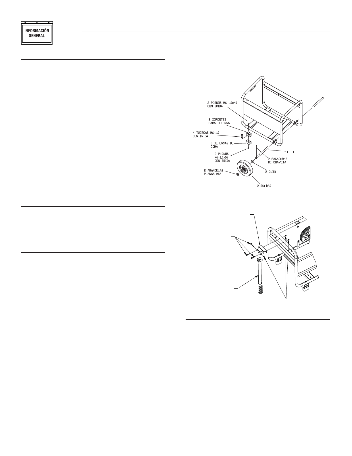
Sección 1 – Información general
Sistema de generador portátil
1.1 DESEMBALAJE
Quite todo el material de embalaje.•
Retire la caja de accesorios que viene por separado.•
Retire el generador de la caja.•
1.1.1 CAJA DE ACCESORIOS
Revise todo el contenido. Si falta alguna pieza o encuentra alguna dañada,
llame al teléfono 1-888-436-3722 para encontrar un concesionario
autorizado.
1 - Manual del propietario•
1- Aceite tipo SAE 30•
2 - Ruedas de 7”•
1 - Conjunto de la manija•
1 - Abrazadera de la manija•
1 - Eje•
1 - Bolsa con piezas (incluye lo siguiente):•
2 - Sopor tes de goma 7 - Tuercas tapón M6
2 - Abrazaderas de sopor te 2 - Cubo
2 - Ruedas 7 - Pernos tapón M6-1 x 40
2 - Arandelas planas M12
1.2 MONTAJE
El generador requiere cier to montaje antes de poder usarlo. Si surgen
problemas durante dicho montaje, llame a la línea telefónica de ayuda
sobre generadores: 1-888-436-3722.
1.2.1 MONTAJE DEL JUEGO DE ACCESORIOS
Las ruedas están diseñadas para mejorar en gran medida la facilidad de
transporte del generador.
NOTA:
Las ruedas no son para uso en carretera.
1. Consulte la Figura 1 para instalar las ruedas como se indica.
• Deslice el eje pro los sapor tes del marco.
• Deslice el cubo, la rueda y la arandela plana, y luego instale la
chaveta de retén en el orificio del eje de las ruedas.
• Doble hacia afuera las orejetas de la chaveta de retén para fijarla
en su lugar.
2. Consulte la Figura 1 para instalar los soportes como se muestra.
• Inserte un perno M6 a través del soporte de goma y de la parte
inferior de la abrazadera de soporte. Asegure el per no con una
tuerca tapón M6.
• Instale un perno M6 a través del bastidor del generador y de la
parte superior de la abrazadera de sopor te. Asegure el perno
con una tuerca tapón M6.
3. Consulte la Figure 2 para instalar el conjunto de la manija como se
muestra.
• Inserte la abrazadera de la manija en el bastidor del generador y
asegúrela con dos pernos M6 y dos tuercas tapón M6.
• Alinee los orificios del conjunto de la manija con los orificios de
la abrazadera de la manija y asegúrelos con un perno M6 y una
tuerca tapón M6.
Figura 1 – Ensamblaje de las ruedas
Figura 2 – Kit de manija
SOPORTE DE MANIJA
3 PERNOS M6-1,0x40
CON BRIDA
ENSAMBLE DE LA MANIJA
3 TUERCAS M6-1,0
CON BRIDA
2.1 FAMILIARÍCESE CON SU GENERADOR
Lea el Manual del Propietario y las Reglas de Seguridad antes de
operar este generador.
Compare el generador con las Figuras 3 a 5 para familiarizarse con
la ubicación de los distintos controles y ajustes. Guarde este material
para referencia futura.
1. Receptáculo dúplex de 120 V de CA, 20 A – Suministra alimentación
eléctrica para la operación de dispositivos de alumbrado eléctrico,
electrodomésticos, herramientas y cargas de motor de 120 V de CA,
20 A, monofásicos y de 60 Hz.
2. Interruptores de circuito (AC) –Cada receptáculo está provisto con
un interruptor de circuito de presionar para reiniciar de 13.5A con el
fin de proteger al generador contra sobrecargas eléctricas.
3.
Filtro de aire – Filtra aire de entrada cuando es aspirado hacia el motor.
4.
Perilla del cebador – Se usa para poner en marcha un motor frío.
22
Page 25

Sección 2 – Operación
Sistema de generador portátil
5. Tanque de combustible – El tanque tiene capacidad para 4 galones
americanos de combustible.
6.
Orejeta de conexión a tierra – Conecta el generador a una tierra apropiada.
Vea los detalles en la sección "Conexión a tierra del generador".
7.
Conmutador de inicio/parada – Controla la operación del generador.
8. Silenciador – Atenúa el ruido del motor.
9. Manija– Gira y se retrae para su almacenamiento.
10. Tapa del tanque – Lugar para poner el combustible.
11. Indicador de combustible – Muestra el nivel de combustible en el
tanque.
12. Revisión y llenado de aceite– Revise y vierta el aceite aquí.
13.
Arranque manual – Su usa para poner en marcha manualmente el motor.
14. Llave de corte de combustible – Válvula entre el tanque del
combustible y el carburador.
15.
Tapón de drenaje del aceite – Se usa para drenar el aceite del motor.
16. Supresor de chispas – Contiene las chispas para reducir el riesgo
de incendio.
17. Válvula de grio – Pasa los vapores del combustible a bote de
Carb
ó
n.
18. Bote de Carb
19. Manguera e recuperaci
ón
– Absorbe los vapores del tanque de combustible.
ón
– Instalada entre los items 17 y 18.
Figura 3 - Panel de control
7
21
15
Figura 5 - Controles del generador
7
16
8
12
6
Figura 6 - Controles del generador
6
Figura 4 - Controles del generador
17
19
18
19
23
Page 26

Sección 2 – Operación
PELIGRO
Sistema de generador portátil
2.2
JUEGOS DE CABLES ELÉCTRICOS Y CONECTORES
2.2.1 RECEPTÁCULO DÚPLEX DE 120 V DE CA, 20 A
Este receptáculo es un tomacorriente de 120 V protegido contra
sobrecargas por un disyuntor de restablecimiento por presión de
13.5 A (Figura 3). Cada receptáculo puede alimentarse con 13.5 A
de corriente, pero la alimentación total debe mantenerse dentro de
los límites establecidos en la placa de datos. Use sólo juegos de
cables eléctricos de tres hilos, conectados a tierra, bien aislados,
de alta calidad, clasificados para 125 V a 20 A (o más).
2.3 CÓMO USAR EL GENERADOR
Si tiene algún problema al operar el generador, por favor llame a la línea
telefónica de ayuda sobre generadores, 1-888-436-3722.
Si usa un generador en interiores, MORIRÁ EN
POCOS MINUTOS. El escape contiene monóxido de
carbono, un gas venenoso que no se ve ni huele a
nada.
NUNCA lo use en el hogar ni en áreas parcialmente
encerradas como los garajes. Úselo SÓLO en
exteriores y lejos de ventanas abiertas, puertas,
ductos de ventilación y en áreas que no acumularán
el mortal gas del escape.
DANGER
Using a generator indoors WILL KILL YOU IN MINUTES. Exhaust contains
carbon monoxide, a poison gas you cannot see or smell.
NEVER use in the home or in partly enclosed areas such as garages.
ONLY use outdoors and far from open windows, doors and vents.
2.3.1 CONEXIÓN A TIERRA DEL GENERADOR
El Código Eléctrico Nacional requiere que el bastidor y las
piezas externas eléctricamente conductoras de este generador se
conecten a una conexión a tierra aprobada (Figura 7). Los códigos
eléctricos locales también pueden requerir la adecuada conexión a
tierra de la unidad. Con ese objetivo, la conexión de un cable de cobre
No. 10 AWG (American Wire Gauge) a la orejeta de conexión a tierra
y a una barra de conexión a tierra de cobre o de bronce (electrodo)
proporciona una conexión adecuada contra las descargas eléctricas.
Sin embargo, los códigos locales pueden variar. Consulte con un
electricista local para averiguar cuáles son los requisitos en su
área.
La conexión a tierra adecuada del generador ayudará a evitar
descargas eléctricas en el caso de que exista una condición de falla
a tierra en el generador o en los dispositivos eléctricos conectados.
Una buena conexión a tierra también ayuda a disipar la electricidad
estática, la cual se acumula frecuentemente en dispositivos no
conectados a tierra.
24
Figura 7 -
Conexión a tierra del generador
2.3.2 CONEXIÓN DE LAS CARGAS ELÉCTRICAS
NO conecte cargas de 240 V en receptáculos de 120 V. NO conecte
cargas trifásicas en el generador. NO conecte cargas de 50 Hz en el
generador.
Deje que el motor se estabilice y caliente durante unos minutos •
después de que arranque.
Enchufe y encienda las cargas eléctricas monofásicas de 120 o de •
240 V de CA de 60 Hz deseadas.
Sume los vatios (o amperios) nominales de todas las cargas que •
se van a conectar al mismo tiempo. Este total no debe ser mayor
que (a) la capacidad nominal en vatios/amperios del generador
o (b) la capacidad nominal del disyuntor del receptáculo que
suministra la potencia. Consulte la sección "No sobrecargue el
generador"
.
2.4 NO SOBRECARGUE EL GENERADOR
Cuando un generador se carga superando su capacidad nominal en
vatios pueden causarse daños al generador y a los dispositivos eléctricos
conectados. Siga estas instrucciones para evitar la sobrecarga de la
unidad:
Sume el vataje total de todos los dispositivos eléctricos que se van •
a conectar a la vez. Este total NO debe exceder la capacidad del
generador en vatios.
El vataje nominal de las lámparas se puede tomar de las bombillas. •
El vataje nominal de las herramientas, electrodomésticos y motores
usualmente se puede encontrar en la etiqueta de datos o en la
calcomanía pegada en el dispositivo.
Si el electrodoméstico, la herramienta o el motor no tiene el vataje, •
multiplique los voltios por la clasificación nominal en amperios para
determinar los vatios (voltios x amperios = vatios).
Algunos motores eléctricos, como los de inducción, requieren •
aproximadamente tres veces más vataje de potencia para ponerse
en marcha que para funcionar. Esta sobretensión sólo dura unos
segundos cuando se arrancan tales motores. Asegúrese de permitir un
alto vataje de arranque cuando seleccione los dispositivos eléctricos
que va a conectar al generador.
1. Calcule los vatios necesarios para poner en marcha el motor de
mayor tamaño.
2. Sume a esa cifra los vatios de operación de todas las demás cargas
conectadas.
Se proporciona una guía de referencia de vataje para ayudarle a determinar
el número de artículos que el generador puede alimentar a la vez.
Page 27
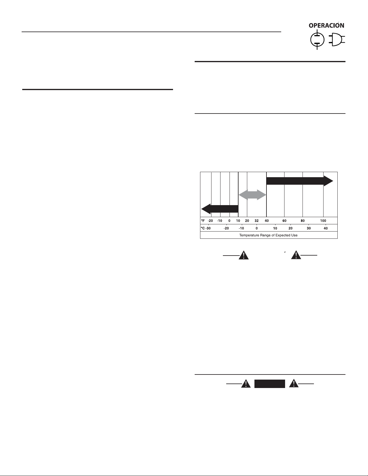
10 W- 30
SA E 30
Sy nt he ti c 5W -3 0
Sección 2 – Operación
Sistema de generador portátil
NOTA:
T odas las cifras son aproximadas. Consulte la etiqueta de datos del
electrodoméstico para ver los vatios requeridos.
2.5 GUÍA DE REFERENCIA DEL VATAJE
Dispositivo. . . . . . . . . . . . . . . . . . . . . . . . . . . . . . . Vataje de operación
*Unidad de acondicionamiento de aire (12,000 Btu). . . . . . . . . . . . 1700
*Unidad de acondicionamiento de aire (24,000 Btu). . . . . . . . . . . . 3800
*Unidad de acondicionamiento de aire (40,000 Btu). . . . . . . . . . . . 6000
Cargador de batería (20 A) . . . . . . . . . . . . . . . . . . . . . . . . . . . . . . . . 500
Lijadora de correa (3") . . . . . . . . . . . . . . . . . . . . . . . . . . . . . . . . . . 1000
Sierra de cadena. . . . . . . . . . . . . . . . . . . . . . . . . . . . . . . . . . . . . . . 1200
Sierra circular (6-1/2") . . . . . . . . . . . . . . . . . . . . . . . . . . . . . 800 a 1000
*Secadora de ropa (eléctrica) . . . . . . . . . . . . . . . . . . . . . . . . . . . . 5750
*Secadora de ropa (a gas). . . . . . . . . . . . . . . . . . . . . . . . . . . . . . . . 700
*Lavadora de ropa . . . . . . . . . . . . . . . . . . . . . . . . . . . . . . . . . . . . . 1150
Cafetera . . . . . . . . . . . . . . . . . . . . . . . . . . . . . . . . . . . . . . . . . . . . . 1750
*Compresor (1 HP) . . . . . . . . . . . . . . . . . . . . . . . . . . . . . . . . . . . . 2000
*Compresor (3/4 HP). . . . . . . . . . . . . . . . . . . . . . . . . . . . . . . . . . . 1800
*Compresor (1/2 HP). . . . . . . . . . . . . . . . . . . . . . . . . . . . . . . . . . . 1400
Tenazas para el pelo. . . . . . . . . . . . . . . . . . . . . . . . . . . . . . . . . . . . . 700
*Deshumidificador . . . . . . . . . . . . . . . . . . . . . . . . . . . . . . . . . . . . . . 650
Lijadora de disco (9"). . . . . . . . . . . . . . . . . . . . . . . . . . . . . . . . . . . 1200
Recortadora de césped. . . . . . . . . . . . . . . . . . . . . . . . . . . . . . . . . . . 500
Manta eléctrica. . . . . . . . . . . . . . . . . . . . . . . . . . . . . . . . . . . . . . . . . 400
Pistola eléctrica de clavos. . . . . . . . . . . . . . . . . . . . . . . . . . . . . . . . 1200
Estufa eléctrica (por elemento). . . . . . . . . . . . . . . . . . . . . . . . . . . . 1500
Cacerola eléctrica. . . . . . . . . . . . . . . . . . . . . . . . . . . . . . . . . . . . . . 1250
*Congelador . . . . . . . . . . . . . . . . . . . . . . . . . . . . . . . . . . . . . . . . . ..700
*Ventilador de horno (3/5 HP) . . . . . . . . . . . . . . . . . . . . . . . . . . . . . 875
*Abridor de la puerta de la cochera . . . . . . . . . . . . . . . . . . . . 500 a 750
Secador de pelo. . . . . . . . . . . . . . . . . . . . . . . . . . . . . . . . . . . . . . . 1200
Taladro portátil . . . . . . . . . . . . . . . . . . . . . . . . . . . . . . . . . . . 250 a 1100
Recortadora de césped. . . . . . . . . . . . . . . . . . . . . . . . . . . . . . . . . . . 450
Taladro percutor . . . . . . . . . . . . . . . . . . . . . . . . . . . . . . . . . . . . . . . . 500
Plancha . . . . . . . . . . . . . . . . . . . . . . . . . . . . . . . . . . . . . . . . . . . . . 1200
*Bomba de chorro . . . . . . . . . . . . . . . . . . . . . . . . . . . . . . . . . . . . . . 800
Podadora . . . . . . . . . . . . . . . . . . . . . . . . . . . . . . . . . . . . . . . . . . . . 1200
Bombilla eléctrica . . . . . . . . . . . . . . . . . . . . . . . . . . . . . . . . . . . . . . . 100
Horno de microondas. . . . . . . . . . . . . . . . . . . . . . . . . . . . . . 700 a 1000
*Enfriador de leche. . . . . . . . . . . . . . . . . . . . . . . . . . . . . . . . . . . . . 1100
Quemador de aceite en la caldera. . . . . . . . . . . . . . . . . . . . . . . . . . . 300
Radiador de aceite (140,000 Btu). . . . . . . . . . . . . . . . . . . . . . . . . . . 400
Radiador de aceite (85,000 Btu). . . . . . . . . . . . . . . . . . . . . . . . . . . . 225
Radiador de aceite (30,000 Btu). . . . . . . . . . . . . . . . . . . . . . . . . . . . 150
*Rociador de pintura sin aire (1/3 HP) . . . . . . . . . . . . . . . . . . . . . . . 600
Rociador de pintura sin aire (portátil) . . . . . . . . . . . . . . . . . . . . . . . . 150
Radio . . . . . . . . . . . . . . . . . . . . . . . . . . . . . . . . . . . . . . . . . . . . 50 a 200
*Refrigerador . . . . . . . . . . . . . . . . . . . . . . . . . . . . . . . . . . . . . . . . . . 700
Cacerola de cocimiento lento . . . . . . . . . . . . . . . . . . . . . . . . . . . . . . 200
*Bomba sumergible (1-1/2 HP) . . . . . . . . . . . . . . . . . . . . . . . . . . . 2800
*Bomba sumergible (1 HP) . . . . . . . . . . . . . . . . . . . . . . . . . . . . . . 2000
*Bomba sumergible (1/2 HP). . . . . . . . . . . . . . . . . . . . . . . . . . . . . 1500
*Bomba de sumidero. . . . . . . . . . . . . . . . . . . . . . . . . . . . . . 800 a 1050
*Sierra de mesa (10") . . . . . . . . . . . . . . . . . . . . . . . . . . . . 1750 a 2000
Televisor. . . . . . . . . . . . . . . . . . . . . . . . . . . . . . . . . . . . . . . . . 200 a 500
Tostadora. . . . . . . . . . . . . . . . . . . . . . . . . . . . . . . . . . . . . . 1000 a 1650
Cortador de hierbas . . . . . . . . . . . . . . . . . . . . . . . . . . . . . . . . . . . . . 500
* Permita tres veces el vataje listado para poner en marcha estos
dispositivos.
2.6 ANTES DE PONER EN MARCHA EL GENERADOR
Antes de operar el generador se debe añadir aceite de motor y
gasolina, de la siguiente manera:
2.6.1 ADICIÓN DE ACEITE DEL MOTOR
Todo el aceite debe cumplir como mínimo con la clase de servicio SJ,
SL o mejor, del American Petroleum Institute (API). No use aditivos
especiales. Seleccione el grado de viscosidad del aceite de acuerdo con
la temperatura de operación esperada (consulte también la tabla).
Cuando la temperatura sea superior a 40 °F, use aceite SAE 30•
Cuando la temperatura esté entre 40 °F y 10 °F, use aceite 10W-30•
Cuando la temperatura sea inferior a 10 °F, use aceite sintético 5W-30•
SAE 30
10W-30
Synthetic 5W-30
PRECAUCION
Todo intento de iniciar o poner en marcha el motor
antes de hacerle un mantenimiento apropiado con
el aceite recomendado puede provocar un fallo del
motor.
Coloque el generador sobre una superficie nivelada.•
Limpie el área circundante al orificio de llenado y quite al tapa del •
orificio y la varilla de medición de aceite.
Limpie la varilla de medición de aceite.•
Llene lentamente el motor con aceite a través de la abertura del •
conducto para aceite hasta que alcance la marca de lleno en las roscas
de la varilla medidora. Ocasionalmente deje de llenar para revisar el
nivel de aceit. Tenga cuidado de no llenar demasiado.
Instale la tapa del orificio de llenado de aceite y apriétela con los dedos •
firmemente.
A partir de aquí, revise el nivel de aceite antes de cada ar ranque.•
2.6.2 ADICIÓN DE GASOLINA
PELIGRO
Nunca llene el tanque de combustible en
interiores. Nunca llene el tanque de combustible
cuando el motor esté funcionando o cuando esté
caliente. Permita que el motor se enfríe totalmente
antes de llenar el tanque de combustible. Evite
derramar la gasolina sobre el motor CALIENTE.
NO encienda un cigarrillo ni fume al llenar el
tanque de combustible. La gasolina es altamente
INFLAMABLE y sus vapores son EXPLOSIVOS.
25
Page 28

Sección 2 – Operación
Sistema de generador portátil
PRECAUCION
No llene excesivamente el tanque de combustible..
Siempre deje espacio para la expansión del
combustible. Si el tanque está demasiado lleno,
el combustible se puede derramar sobre un motor
CALIENTE y causar un INCENDIO o una EXPLOSIÓN.
Utilice gasolina regular SIN PLOMO con el motor del generador. No •
utilice ningún tipo de gasolina que tenga más de 10% de Etanol
añadido y nunca utilice gasolina E85. No mezcle aceite con gasolina.
Limpie el área alrededor de la tapa de llenado de combustible y quite •
la tapa.
Añada lentamente gasolina regular sin plomo al tanque de combustible. •
Llene hasta el fondo del filtro de malla. Tenga cuidado de no llenar
excesivamente (Figura 8).
Instale la tapa de combustible y limpie cualquier derrame de gasolina. •
Figura 8 - Tanque de combustible
Coloque la perilla del CEBADOR del motor en la posición • START
(arranque) (Figura 10).
Para poner en marcha el motor, sujete con firmeza la manija del •
arranque manual y tire lentamente hasta sentir una resistencia mayor.
Tire con rapidez y hacia afuera.
Figura 9 - Válvula de cierre de combustible
Palanca de
Choke
Manubrio de arranque
de recule
Válvula de corte combustible
Interruptor de
encendido/apagado
NO LLENE POR ENCIMA
DEL REBORDE
IMPORTANTE: Es importante evitar la formación de depósitos de goma
en las piezas del sistema de combustible, tales como en el carburador,
la manguera de combustible o el tanque durante el almacenamiento.
Los combustibles mezclados con alcohol (llamados gasohol, etanol
o metanol) pueden atraer humedad, que provoca la separación y la
formación de ácidos durante el almacenamiento. El gas ácido puede
dañar el sistema de combustible de un motor en almacenamiento. Para
evitar problemas con el motor, el sistema de combustible se debe vaciar
antes de almacenar el motor durante 30 días o más. Consulte la sección
"Almacenamiento". Nunca use productos para la limpieza del motor o del
carburador en el tanque de combustible pues lo podría dañar de manera
permanente.
2.7 ARRANQUE DEL MOTOR
ADVERTENCIA
Nunca arranque ni detenga el motor cuando
haya dispositivos eléctricos enchufados en los
receptáculos Y los dispositivos estén encendidos.
Desenchufe todas las cargas eléctricas de los receptáculos de la •
unidad antes de poner en marcha el motor.
Asegúrese de que la unidad se encuentre en una posición nivelada.•
G• ire la valvula de cier re de combustible a la posición ON (figura 9).
Ponga el conmutador ON/OFF en posición • ON (encendido) (Figura 10).
26
Cuando el motor arranque, coloque la perilla del cebador en la posición •
1/2-CHOKE (cebado medio) hasta que el motor funcione suavemente
y luego totalmente hasta la posición RUN (funcionamiento). Si el
motor vacila, mueva la perilla de cebado otra vez a la posición 1/2CHOKE (cebado medio) hasta que el motor funcione suavemente, y
luego coloque la perilla en la posición RUN (funcionamiento).
Figura 10 - Posición de cebado
Posición de cebado
NOTA:
Si el motor arranca pero no sigue funcionando, mueva la perilla de
cebado hasta la posición START (arranque) y repita las instrucciones de
arranque.
Page 29

Sección 3 — Mantenimiento
Sistema de generador portátil
MANTENIMIENTO
IMPORTANTE: No sobrecargue el generador. Tampoco sobrecargue los
receptáculos individuales del panel. Estos tomacorrientes están protegidos
contra sobrecargas con disyuntores del tipo de restablecimiento por
presión. Si se excede la capacidad nominal en amperios de cualquier
disyuntor, éste se abrirá y se perderá la salida eléctrica a ese receptáculo.
Lea detenidamente la sección "No sobrecargue el generador".
2.8 DETENCIÓN DEL MOTOR
Apague todas las cargas, luego desenchufe las cargas eléctricas de •
los receptáculos del panel del generador . Nunca arranque ni detenga el
motor cuando haya dispositivos eléctricos enchufados y encendidos.
Deje que el motor funcione sin carga durante varios minutos para •
estabilizar las temperaturas internas del motor y del generador.
Mueve el conmutador ON/OFF a la posición • OFF (Apagado).
Cierre la válvula de combustible.•
2.9 SISTEMA DE APAGADO POR BAJO NIVEL DE ACEITE
El motor está equipado con un sensor de bajo nivel de aceite que apaga
el motor automáticamente cuando el nivel del aceite cae por debajo de
un nivel especificado. Si el motor se apaga por sí solo y el tanque tiene
suficiente gasolina, revise el nivel de aceite del motor.
2.9.1 DETECCIÓN DE BAJO NIVEL DE ACEITE
Si el sistema detecta un nivel de aceite bajo durante la operación, el motor
se apaga. El motor no funcionará hasta que se llene el aceite hasta el nivel
correcto.
3.1 PROGRAMA DE MANTENIMIENTO
Siga los intervalos marcados en el calendario. El mantenimiento debe ser
más frecuente cuando se opera en las condiciones adversas indicadas
más abajo
Revise el nivel de aceite Antes de cada uso
Cambie el aceite + *Cada temporada
Revise la holgura de la válvula ***Cada temporada
Mantenimiento del filtro de aire **Cada temporada
Reemplace la bujía Cada temporada
+ Cambie el aceite luego de las primeras 20 horas de operación y luego en cada
cambio de estación.
* Cambie el aceite cada mes si opera bajo condiciones pesadas de carga o
altas temperaturas.
** Limpie con más frecuencia bajo condiciones de operación sucias o con
polvo. Reemplace los componentes del filtro de aire si no puede limpiarlos
correctamente.
*** Revise el espacio de la válvula y ajústelo si es necesario después de las
primeras 50 horas de operación y posteriormente cada 100 horas.
3.2 ESPECIFICACIONES DEL PRODUCTO
3.2.1 ESPECIFICACIONES DEL GENERADOR
Potencia nominal ......................................................................3.25 kW
Potencia de sobretensión ..........................................................3.75 kW
Voltaje CA nominal ....................................................................120/240
Corriente nominal ....................................................................... 27 A**
Frecuencia nominal .................................................. 60 Hz a 3600 RPM
Fase .....................................................................................Monofásico
** El vataje máximo depende y está limitado por factores como el
contenido de Btu del combustible, la temperatura ambiente, la altitud,
el estado del motor, etc. La potencia máxima disminuye alrededor del
3.5% por cada 1,000 pies sobre el nivel del mar; y también disminuye
alrededor del 1% por cada 6° C (10° F) que la temperatura ambiente
está por encima de 16° C (60° F).
3.2.2 ESPECIFICACIONES DEL MOTOR
Desplazamiento...........................................................................208 cc
Tipo de bujía .........................................................F6TC o NGK BPR4ES
Separación entre los electrodos de la
bujía ............................ 0.028-0.031 de pulgada o (0.70-0.80 mm)
Capacidad para gasolina ....................................... 16 L (0.634 cuartos)
Tipo de aceite .........................................Consulte la tabla en la sección
"Antes de poner en marcha el
generador"
Capacidad para aceite ..........................................0.6 L (0.634 cuartos)
Tiempo de funcionamiento ..................................12.5 horas a 1/2 carga
Certificado de emisión clase II*
* El fabricante del motor debe garantizar el sistema de control de
emisiones durante un período de dos años. La cobertura de esta
garantía es adicional a la proporcionada por Generac, y puede cubrir el
motor aún si la garantía de Generac no lo hace.
3.3 RECOMENDACIONES GENERALES
La garantía del generador no cubre artículos que han sido sometidos a
abuso o negligencia por parte del operador. Para recibir el valor total de
la garantía, el operador debe mantener el generador de acuerdo con las
instrucciones de este manual.
Será necesario hacer algunos ajustes periódicamente para mantener
adecuadamente el generador.
Todos los ajustes indicados en la sección Mantenimiento de este manual
se deben hacer al menos una vez por temporada. Cumpla con los
requisitos indicados en la sección "Programa de mantenimiento".
NOTA:
Una vez al año reemplace la bujía y el filtro de aire. Una bujía
nueva y un filtro de aire limpio aseguran la mezcla adecuada de
aire-combustible y ayudan a que el motor funcione mejor y dure
más.
3.3.1 MANTENIMIENTO DEL GENERADOR
El mantenimiento del generador consiste en mantener la unidad limpia
y seca. Opere y almacene la unidad en un entorno seco y limpio en
el que no esté expuesto a polvo, suciedad o humedad excesivos, ni a
vapores corrosivos. Las ranuras del sistema de enfriamiento por aire
no deben estar obstruidas con nieve, hojas ni cualquier otro material
extraño.
27
Page 30

MANTENIMIENTO
Sección 3 — Mantenimiento
Sistema de generador portátil
Revise frecuentemente la limpieza del generador, y límpielo cuando tenga
polvo, suciedad, aceite, humedad u otro material extraño en su superficie
exterior.
PRECAUCION
Nunca inserte ningún objeto ni herramienta a
través de las ranuras del sistema de enfriamiento
por aire, ni siquiera cuando el motor esté inactivo.
NOTA:
NO use una manguera de jardín para limpiar el generador. El agua
puede entrar en el sistema de combustible del motor y causar
problemas. Además, si entra agua en el generador a través de
las ranuras del sistema de enfriamiento por aire, algo del agua
puede quedar retenida en cavidades y hendiduras del rotor y del
aislamiento del devanado del estator. La acumulación de agua y
de suciedad en el devanado interno del generador eventualmente
reducirá la resistencia del aislamiento de estos devanados.
3.3.2 LIMPIEZA DEL GENERADOR
Use un paño húmedo para limpiar las superficies exteriores del generador.•
Se puede usar un cepillo de cerdas suaves para aflojar la tierra, aceite, •
etc. endurecidos.
Se puede usar una aspiradora para recoger la suciedad y los residuos •
sueltos.
Se puede usar aire de baja presión (no mayor de 25 psi) para •
desempolvar el generador. Inspeccione las ranuras y aberturas del
sistema de enfriamiento por aire del generador. Estas aberturas deben
estar siempre limpias y sin obstrucciones.
3.3.3 MANTENIMIENTO DEL MOTOR
PELIGRO
Cuando trabaje en el generador, siempre desonecte
el cable de la bujía y manténgalo lejos de esta.
3.3.4 MEDICIÓN DEL NIVEL DE ACEITE
Consulte la sección "Antes de poner en marcha el generador" para ver
información sobre la medición del nivel de aceite. Debe medir el nivel de
aceite antes de cada uso del generador, o al menos cada ocho horas de
operación. Mantenga el nivel de aceite (Figura 11).
3.3.5 CAMBIO DEL ACEITE
Cambie el aceite del motor después de las primeras 8 horas de
operación, y después cada 20 horas de operación. Si opera esta
unidad en condiciones sucias o con polvo, o en condiciones climáticas
extremadamente calientes, cambie el aceite con más frecuencia.
PRECAUCION
El aceite caliente puede causar quemaduras.
Permita que el motor se enfríe antes de drenar el
aceite. Evite el contacto prolongado o repetitivo de
la piel con el aceite usado. Lave a fondo con jabón
las zonas expuestas.
Use las siguientes instrucciones para cambiar el aceite mientras el
motor está tibio:
Limpie el área alrededor del tapón de drenaje del aceite.•
Quite el tapón de drenaje del aceite del motor y el tapón de llenado del •
aceite y drene completamente el aceite en un recipiente adecuado.
Cuando haya drenado completamente el aceite, instale el tapón de •
drenaje del aceite y apriételo firmemente.
Llene el motor con el aceite recomendado. (Vea “Antes de arrancar el •
generador” para mayores recomendaciones sobre el aceite).
Limpie todo el aceite que se haya derramado.•
Deseche el aceite usado en un centro de recolección autorizado.•
3.3.6 REEMPLAZO DE LA BUJÍA
Use una bujía F6TC o NGK BPR4ES. Reemplace la bujía cada año. Esto
ayudará a que el motor arranque más fácilmente y funcione mejor.
1. Detenga el motor y desconecte el cable de la bujía.
2. Limpie el área alrededor de la bujía y quítela del cabezal del cilindro.
3. Ajuste la separación de los electrodos de la bujía entre 0.70-0.80
mm (0.028-0.031 pulgadas). Instale la bujía con la separación
correcta entre electrodos en el cabezal del cilindro y ajústela a 15
pies/libra (Figura 12).
Figura 12 - Separación entre los electrodos de la bujía
28
Figura 11 - Drenaje, revisión y llenado de aceite
Drenaje de Aceite
Cheque y Relleno
de Aceite
3.3.7 MALLA AMORTIGUADORA DE CHISPAS
1. Apague el generador y permita que el motor y el silenciador se
enfríen completamente antes de trabajar en la malla amortiguadora
de chispas (ubicada en la parte posterior del silenciador).
2. Quite la grampa y la malla amortiguadora de chispas.
3. Limpie la malla amortiguadora de chispas con un cepillo de alambre
pequeño.
4. Reemplace la malla amortiguadora de chispas si está dañada.
5. La malla amortiguadora de chispas se instala en el orden inverso al
seguido para quitarla.
Page 31
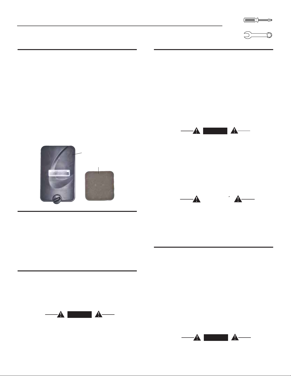
Sección 3 — Mantenimiento
Sistema de generador portátil
MANTENIMIENTO
3.4 MANTENIMIENTO DEL FILTRO DE AIRE
El motor no funcionará correctamente y puede dañarse si el filtro de aire
está sucio. Limpie el filtro de aire una vez al año (Figura 13). Límpielo o
reemplácelo con más frecuencia si el generador se opera bajo condiciones
con mucho polvo.
Desmonte la cubierta del filtro de aire.•
Lávelo con agua jabonosa. Seque el filtro de aire apretándolo con un •
paño limpio (NO LO RETUERZA).
Limpie la cubierta del filtro de aire antes de volverla a instalar.•
NOTA:
Si desea pedir un nuevo filtro de aire, comuníquese con el
centro de servicio autorizado más cercano llamando al 1-888436-3722.
Figura 13 - Filtro de aire
Aire limpia Cobertura
filtro de aire
3.7 ALMACENAMIENTO A LARGO PLAZO
Es importante evitar la formación de depósitos de goma en las piezas
del sistema de combustible, como en el carburador, la manguera
de combustible o el tanque durante el almacenamiento. Además,
la experiencia indica que los combustibles mezclados con alcohol
(llamados gasohol, etanol o metanol) pueden atraer humedad,
que provoca la separación y la formación de ácidos durante el
almacenamiento. El gas ácido puede dañar el sistema de combustible
de un motor en almacenamiento.
Para evitar problemas con el motor, el sistema de combustible se debe
vaciar antes de almacenar el motor durante 30 días o más, de la manera
siguiente:
Saque toda la gasolina del tanque de combustible.•
PELIGRO
Drene el combustible en un recipiente adecuado en
el exterior, lejos de llamas expuestas. Asegúrese de
que el motor esté frío. No fume.
Arranque y opere el motor hasta que éste se detenga por falta de •
combustible.
Mientras el motor está aún caliente, drene el aceite del cárter. Vuelva a •
llenar el cárter con aceite del grado recomendado.
Quite las bujías y vierta aproximadamente 1/2 onza (15 ml) de aceite •
de motor en los cilindros. Cubra el orificio de las bujías con un trapo.
Tire del arranque manual un par de veces para lubricar los aros del
pistón y el interior del cilindro.
3.5 HOLGURA DE LA VÁLVULA
Admisión — 0.10 ± 0.02 mm (en frío), (0.003" ± 0.005" pulgadas)•
Escape — 0.15 ± 0.02 mm (en frío) (0.005" ± 0.007" pulgadas)•
Después de las primeras 50 horas de operación, revise la holgura de
la válvula en el motor y ajuste si es necesario.
Importante: Si se siente incómodo realizando este procedimiento o no
tiene las herramientas adecuadas, lleve el generador al centro de servicio
más cercano para que le ajusten la holgura de la válvula. Éste es un paso
muy importante para asegurar la vida útil más larga posible del motor.
3.6 GENERAL
El generador se debe poner en marcha al menos una vez cada siete
días y se le debe permitir que funcione al menos durante 30 minutos.
Si no es posible hacerlo y la unidad se debe almacenar durante más
de 30 días, utilice la siguiente información como guía para preparar el
generador para su almacenamiento.
PELIGRO
NUNCA almacene el motor con combustible en
el tanque en interiores o en áreas confinadas
deficientemente ventiladas en las que los vapores
puedan llegar hasta una llama expuesta, chispa
o llama piloto, como por ejemplo en una caldera,
calentador de agua, secadora de ropa u otro
electrodoméstico a gas
.
PRECAUCION
Evite el rocío proveniente de los orificios de las
bujías al poner en marcha el motor.
Instale y apriete las bujías. No conecte los cables de las bujías.•
Limpie las superficies externas del generador. Compruebe que las •
ranuras y las aberturas del sistema de enfriamiento por aire estén
libres y sin obstrucciones.
Almacene la unidad en un lugar limpio y seco.•
3.8 OTRAS SUGERENCIAS PARA EL ALMACENAMIENTO
No almacene gasolina de una temporada a otra.•
Reemplace la gasolina si ésta se comienza a oxidar. La corrosión y/o •
la suciedad en la gasolina causarán problemas en el carburador y en
el sistema de combustible.
Si es posible, almacene la unidad en el interior y cúbrala para •
protegerla del polvo y la suciedad. ASEGÚRESE DE VACIAR EL
TANQUE DE COMBUSTIBLE.
Si no es práctico vaciar el tanque de combustible y va a almacenar •
la unidad por un periodo de tiempo, añada un estabilizador de
combustible comercialmente disponible a la gasolina para aumentar
la vida de la gasolina.
Cubra la unidad con una cubierta protectora adecuada que no retenga •
humedad.
PELIGRO
NUNCA cubra el generador mientras el motor y el
área de escape estén calientes.
29
Page 32

Localización
de Defectos
Sección 4 — Localización y resolución de problemas
Sistema de generador portátil
4.1 GUÍA DE LOCALIZACIÓN Y RESOLUCIÓN DE PROBLEMAS
PROBLEMA CAUSA CORRECCIÓN
El motor está funcionando, pero no hay
disponible una salida de CA.
1. El disyuntor está abierto.
2. Hay una mala conexión o el juego de cordones eléctricos
está defectuoso.
3. El dispositivo conectado no funciona.
4. Falla en el generador.
1. Restablezca el disyuntor.
2. Revise y repare.
3. Conecte otro dispositivo que funcione bien.
4. Comuníquese con un centro de servicio autorizado.
El motor funciona bien pero se atasca
cuando se conectan cargas.
El motor no arranca, o arranca y
funciona toscamente.
El motor se apaga durante la
operación.
1. Cortocircuito en una carga conectada.
2. El generador está sobrecargado.
3. La velocidad del motor es demasiado lenta.
4. Cortocircuito en el generador.
1. El filtro de aire está sucio.
2. Se acabó la gasolina.
3. La gasolina está descompuesta.
4. El cable de la bujía no está conectado a la bujía.
5. Bujía defectuosa.
6. La gasolina tiene agua.
7. Cebado excesivo.
8. Bajo nivel de aceite.
9. Mezcla de combustible excesivamente rica.
10. La válvula de entrada se atoró abierta o cer rada.
11. El motor ha perdido compresión.
1. Se acabó la gasolina.
2. Bajo nivel de aceite.
3. Fallo en el motor.
1. Desconecte la carga eléctrica cortocircuitada.
2. Consulte la sección "No sobrecargue el generador".
3. Comuníquese con un centro de servicio autorizado.
4. Comuníquese con un centro de servicio autorizado.
1. Limpie o reemplace el filtro de aire.
2. Llene el tanque de combustible.
3. Drene el tanque de combustible y llénelo con combustible
nuevo.
4. Conecte el cable a la bujía.
5. Reemplace la bujía.
6. Drene el tanque de combustible y llénelo con combustible
nuevo.
7. Coloque la perilla del cebador en la posición No Choke
(sin cebado).
8. Llene el cárter hasta el nivel apropiado..
9. Comuníquese con un centro de servicio autorizado.
10. Comuníquese con un centro de servicio autorizado.
11. Comuníquese con un centro de servicio autorizado.
1. Llene el tanque de combustible.
2. Llene el cárter hasta el nivel apropiado..
3. Comuníquese con un centro de servicio autorizado.
El motor no tiene potencia. 1. La carga es demasiado alta.
2. El filtro de aire está sucio.
3. El motor necesita mantenimiento.
El motor vacila. 1. El cebador se abrió demasiado pronto.
2. El carburador está operando muy pesado o muy ligero.
30
1. Consulte la sección “No sobrecargue el generador”.
2. Reemplace el filtro de aire.
3. Comuníquese con un centro de servicio autorizado.
1. Mueva el cebador a la posición inter media hasta que el
motor funcione sin problemas.
2. Comuníquese con un centro de servicio autorizado.
Page 33

Sección 5 — Notas
31
Page 34

Sección 6 — Garantía
GARANTIA
Sistema de generador portátil
DECLARACIÓN DE GARANTÍA DE CONTROL DE EMISIONES FEDERAL Y DE CALIFORNIA
SUS DERECHOS Y OBLIGACIONES DE GARANTÍA
El directorio de recursos de aire de California (CARB) y la Agencia de protección ambiental de los Estados Unidos (EPA) junto con
Generac Power Systems, Inc. (Generac) se complacen en explicar la garantía del sistema de control de emisiones para su nuevo
generador del año 2008 o posterior. equipo nuevo que use motores pequeños de chispa deben estar diseñados, construidos
y equipados para cumplir estándares anti-smog muy exigentes para el gobierno federal y del Estado de California. Generac
garantizará los sistemas de emisión en su motor por el periodo de tiempo listado abajo siempre que no haya abuso, negligencia,
modificación o mantenimiento inapropiado de su equipo.
Su sistema de control de emisión puede incluir partes como: carburador, sistema de ignición, convertidor catalitico, tanque
de combustible, tapa de combustible, válvulas, lata de carbón, filtros, mangueras de vapor, abrazaderas, conectores, y otros
componentes relacionados a la emisión (si existieran).
COBERTURA DE LA GARANTÍA DEL FABRICANTE:
Este sistema de control de emisión está garantizado por dos años. Si durante este periodo de garantía se encuentra que cualquier
parte relacionada a las emisiones está defectuosa en materiales o mano de obra, se efectuará las reparaciones o el intercambio
por parte de un concesionario de servicio autorizado de Generac.
RESPONSABILIDADES DE GARANTÍA DEL PROPIETARIO:
Como propietario del generador, usted es responsable de completar todos los mantenimientos requeridos tal como se lista en el
manual del propietario proporcionado por la fábrica. Para propósitos de garantía, Generac recomienda que usted conserve todos
los recibos que cubren el mantenimiento de su generador, pero Generac no puede rehusar la garantía sólo debido a la falta de
recibos.
Como propietario del generador, usted deberá ser consciente de que Generac puede negar cualquier y/o todas las coberturas y
responsabilidades de la garantía si su generador, o una parte o componente del mismo, ha fallado debido al abuso, negligencia,
mantenimiento inapropiado o modificaciones no aprobadas, o el uso de repuestos falsos o del mercado negro no fabricados,
suministrados o aprobados por Generac.
Usted es responsable de contactar a un concesionario autorizado de garantía de Generac tan pronto se presente el
problema. Las reparaciones de garantía deberán completarse en un tiempo razonable, sin exceder los 30 días.
El servicio de garantía puede arreglarse contactando ya sea a su concesionario de venta o a un concesionario de servicio de
garantía autorizado de Generac. Para ubicar al concesionario de servicio de garantía autorizado de Generac más cercano a usted,
llame a nuestro número gratuito.
1-800-333-1322
NOTA IMPORTANTE: Esta declaración de garantía explica sus derechos y obligaciones bajo la Garantía del sistema de
control de emisiones (ECS Warranty), que Generac le proporciona Generac siguiendo las leyes federales y de California.
También vea “Garantías limitadas de Generac para los sistemas de potencia de Generac, Inc.” que se adjunta a este manual
en una hoja separada, también proporcionada a usted por Generac. Tenga en cuenta que esta garantía no se aplicará a
ningún daño incidental, consecuencial o indirecto causado por defectos en los materiales y mano de obra, o cualquier retraso
en reparar o reemplazar las partes defectuosas. Esta garantía reemplaza a todas las otras garantías, expresas o implícitas.
ESPECÍFICAMENTE, GENERAC NO OFRECE OTRAS GARANTÍAS COMO DE MERCANTIBILIDAD O ADECUACIÓN A UN
USO PARTICULAR. Algunos estados no permiten limitaciones en cuánto dura una garantía implícita, de modo que la limitación
expresada arriba puede no aplicarse a usted.
La garantía ECS se aplica sólo al sistema de control de emisiones de su nuevo equipo. Si hay algún conflicto en términos
entre la garantía ECS y la garantía de Generac, se aplicará la de Generac. Ambas garantías describen derechos y obligaciones
importantes respecto a su nuevo motor.
El servicio de garantía puede ser realizado sólo por un servicio de garantía autorizado de Generac. Cuando se requiera servicio de
garantía, se debe presentar evidencia que muestre la fecha de venta al comprador/propietario original.
Si usted tuviera alguna pregunta respecto a sus derechos y responsabilidades de garantía, deberá ponerse en contacto con
Generac en la siguiente dirección:
ATENCIÓN DEPARTAMENTO DE GARANTÍAS
GENERAC POWER SYSTEMS, INC.
P.O. BOX 297 • WHITEWATER, WI 53190
Parte 1
32
Part No. 0H1913 Rev. A 01/09
Page 35

Sección 6 — Garantía
Sistema de generador portátil
GARANTIA
GARANTÍA DEL SISTEMA DE CONTROL DE EMISIONES
Garantía de sistema de control de emisiones (garantía ECS) para equipo que usa motores pequeños de chispa.
(a) Aplicabilidad: Esta garantía se aplica a equipo que utiliza motores pequeños para fuera de pista. El periodo de garantía
ECS empezará en la fecha en que el equipo nuevo es comprado por o entregado a su propietario/comprador final original y
continuará por los siguientes 24 meses consecutivos.
(b) Cobertura general de la garantía de emisiones: Generac garantiza al propietario/comprador final original del motor o
equipamiento nuevo y a cada subsiguiente comprador/propietario que el ECS cuando se instaló estuvo:
(1) Diseñado, construido y equipado para cumplir con todas las regulaciones aplicables: y
(2) Libre de defectos en materiales y mano de obra que cause la falla de una parte garantizada en cualquier momento
durante el periodo de garantía ECS.
(c) La garantía sobre partes relacionadas a la emisión se interpretarán como sigue:
(1) Cualquier parte garantizada que no esté programada para reemplazo como mantenimiento requerido en el Manual del
propietario será garantizada en el periodo de garantía ECS. Si fallara cualquier parte durante el periodo de garantía
ECS, deberá ser reparado o reeemplazado por Generac de acuerdo a la Subsección (4) más abajo. Cualquier parte así
reparada o reemplazada bajo la garantía ECS deberá ser garantizada por el resto del periodo de garantía ECS.
(2) Cualquier parte garantizada que esté programada sólo para inspección regular como se especifica en el Manual del
propietario será garantizada en el periodo de garantía ECS. Una declaración en el manual del propietario a efecto de
“reparar o reemplazar según sea necesario” no reducirá el periodo de garantía ECS. Cualquier parte así reparada o
reemplazada bajo la garantía ECS deberá ser garantizada por el resto del periodo de garantía ECS.
(3) Cualquier parte garantizada que esté programada para reemplazo según lo requiera el mantenimiento en el Manual del
Propietario deberá ser garantizado por el periodo de tiempo antes del primer punto de reemplazo programado para esa
parte. Si la parte falla antes del primer reemplzao programado, la parte será reparada o reemplazada por Generac de
acuerdo a la Subsección (4) más abajo. Cualquier parte relacionada a las emisiones así reparada o reemplazada bajo la
garantía ECS será garantizada por el resto del periodo antes del primer punto de reemplazo programado para aquella
parte.
(4) La reparación o reemplazo de cualquier parte garantizada relacionada a las emisiones bajo esta garantía ECS deberá
realizarse sin costo alguno para el propietario en un centro de servicio de garantía autorizado por Generac.
(5) No obstante las disposiciones de la subsección (4) arriba indicadas, los servicios o reparaciones por garantía deben ser
proporcionados en una instalación de servicio autorizada por Generac.
(6) Cuando el motor sea inspeccionado por un centro de servicio de garantía autorizado de Generac, el propietario/comprador
no será responsable de los costos de diagnóstico si la reparación se considera dentro de la garantía.
(7) A lo largo del periodo de garantía ECS, Generac mantendrá un suministro de partes garantizadas relacionadas a las
emisiones suficiente para cumplir la demanda esperada para tales repuestos.
(8) Cualquier repuesto relacionado a la emisión autorizado y aprobado por Generac puede usarse en la ejecución de cualquir
reparación o mantenimiento de garantía ECS y se proporcionará sin costo al comprador/propietario. Dicho uso no reducirá
las obligaciones de garantía ECS de Generac.
(9) Los repuestos no aprobados, añadidos, modificados, falsos y/o del mercado negro no se pueden usar para modificar
o reparar un motor Generac. Dicho uso invalida esta garantía ECS y será base suficiente para no aceptar un reclamo
por garantía ECS. Generac no podrá ser declarado responsable por fallas de cualquier parte garantizada de un equipo
Generac causadas por el uso de tales repuestos no aprobados, añadidos, modificados, falsos y/o del mercado negro.
LAS PARTES RELACIONADAS A LA EMISIÓN PUEDEN INCLUIR LO SIGUIENTE
(SI SE TIENE):
1) SISTEMA DE COMBUSTIBLE
A. TANQUE DE COMBUSTIBLE
B. TAPA DE COMBUSTIBLE
C. LÍNEA DE COMBUSTIBLE
D. ACCESORIOS DE LA LÍNEA DE COMBUSTIBLE
E. ABRAZADERAS*
F. VÁLVULAS DE LIBERACIÓN DE PRESIÓN*
2) SISTEMA DE CONTROL EVAPORADOR
A. LATA DE CARBÓN
B. SOPORTES DE MONTAJE DE LA LATA
C. PUERTO DE PURGA DEL CARBURADOR
D. VÁLVULAS DE CONTROL*
E. MANGUERAS DE VAPOR
F. VÁLVULAS DE PURGA
G. SEPARADOR LÍQUIDO / VAPOR
H. DIAFRAGMAS DE CONTROL DE VACÍO*
*NOTA: Como se relacionen con el sistema de control de emisiones.
Parte 2
3) SISTEMA DE MEDICIÓN DE COMBUSTIBLE
A. CARBURADOR Y PARTES INTERNAS
B. REGULADOR DE PRESIÓN
4) SISTEMA DE INDUCCIÓN DE AIRE
A. DISTRIBUIDOR DE ENTRADA
B. FILTRO DE AIRE
5) SISTEMA DE IGNICIÓN
A. BUJÍAS
B. BOBINAS/MÓDULO DE IGNICIÓN
6) SISTEMA DE INYECCIÓN DE AIRE
A. VÁLVULA DE AIRE DE PULSO
7) SISTEMA DE ESCAPE
A. CATALIZADOR
B. REACTOR TÉRMICO
C. DISTRIBUIDOR DE ESCAPE
Part No. 0H1913 Rev. A 01/09
33
Page 36

Sección 6 — Garantía
GARANTIA
Sistema de generador portátil
GARANTÍA LIMITADA DE “DOS AÑOS” DE GENERAL POWERS SYSTEMS PARA LOS GENERADORES
PORTÁTILES DE LA SERIE GP
Durante el período de dos años a partir de la fecha original de venta, Generac Power Systems, Inc. (Generac) garantiza que sus generadores de la serie GP no poseen
defectos de materiales ni de mano de obra por los elementos y período establecidos en este documento. Generac, a su discreción, reparará o reemplazará cualquier
parte que, luego de ser sometida a examen, inspección y prueba por parte de Generac o de un distribuidor de servicio autorizado en garantía de Generac, se encuentre
defectuosa. Cualquier equipo que el comprador/propietario considere defectuoso deberá devolverlo para que sea examinado por el distribuidor de servicio autorizado en
garantía de Generac. Todos los costos de transporte bajo esta garantía, incluyendo el de devolución a la fábrica deben ser costeados y prepagados por el comprador/
propietario. Esta garantía aplica únicamente a los generadores portátiles de la serie GP de Generac y no es transferible con respecto al comprador original. Guarde su
recibo de prueba de compra. Si no proporciona prueba de la fecha de compra inicial, la fecha de envío del fabricante del producto se utilizará para deter minar el período
de garantía.
PROGRAMACIÓN DE LA GARANTÍA
Las aplicaciones de los consumidores están garantizadas por dos (2) años. Las aplicaciones comerciales o de alquiler están garantizadas por un (1) año o un máximo de
1.000 horas, lo que ocurra primero.
APLICACIÓN DEL CONSUMIDOR
PRIMER y SEGUNDO AÑO – 100% (cien por ciento) cobertura en mano de obra y pieza(s) indicada(s) (se requiere prueba de compra y de mantenimiento):
• Motor – Todos los componentes
• Alternador – Todos los componentes
APLICACIÓN COMERCIAL/ALQUILER
DURANTE UN AÑO – 100% (cien por ciento) cobertura en mano de obra y pieza(s) indicada(s) (se requiere pr ueba de compra y de mantenimiento):
• Motor – Todos los componentes
• Alternador – Todos los componentes
NOTA: A los fines de esta garantía “uso del consumidor” significa el uso personal residencial doméstico o de recreación por parte del comprador original. Esta garantía no
aplica a unidades que se utilicen como fuente primaria de energía en lugar de los servicios públicos donde estos estén presentes o donde el servicio público no exista
normalmente. Una vez que el generador haya estado sujeto a uso comercial o de alquiler, se considerará en lo sucesivo como un generador de uso no personal para los
fines de esta garantía.
Todos los gastos relacionados con la garantía están sujetos a las condiciones definidas en las Políticas y Procedimientos de Garantía y el Manual de Flete Plano de Generac.
ESTA GARANTÍA NO APLICA A LO SIGUIENTE:
Generadores portátiles fabricados por Generac antes de mayo 2008.•
Costos de mantenimiento y ajustes normales.•
Fallas causadas por combustibles, aceites contaminados, o la falta de niveles adecuados de aceite.•
Reparaciones o diagnósticos efectuados por personas distintas de los distribuidores autorizados Guardian/Generac que no estén autorizados por escrito por parte de Generac •
Power Systems.
Fallas debidas al desgaste por uso normal, accidente, uso inadecuado, abuso, negligencia o utilización inadecuada, pero sin limitarse a ellos. Como con todos los dispositi-•
vos mecánicos, los motores de Generac necesitan servicio y reemplazo periódico de piezas para funcionar en la forma para la cual fueron diseñados. Esta garantía no ampara
la reparación cuando el uso normal haya agotado la vida de una(s) pieza(s) o del motor.
Las fallas ocasionadas por causas externas o causas naturales, tales como choque, robo, vandalismo, motín o guerras, holocausto nuclear, fuego, congelación, rayos, ter-•
remotos, tormentas de viento, granizo, erupción volcánica, agua o inundación, tornados o huracanes.
Daños relacionados con roedores o infestación de insectos. •
Productos que hayan sido modificados o alterados de forma no autorizada por Generac por escrito.•
Cualesquiera daños accidentales, resultantes o indirectos ocasionados por defectos en materiales o mano de obra o cualquier demora en la reparación o reemplazo de la(s) •
parte(s) defectuosa(s).
Fallas ocasionadas por la aplicación indebida.•
Gastos de teléfono, teléfono celular, fax, acceso a Internet u otros gastos relacionados con las comunicaciones. •
G astos de viaje o viáticos de la(s) persona(s) que efectúe(n) servicio, excepto como se incluya específicamente dentro de los términos de un período de garantía específico para una •
unidad.
Gastos relacionados con la “instrucción al cliente” o solución de problemas donde no se encuentre defecto de fabricación.•
Equipos en alquiler utilizados mientras se efectúen las reparaciones en garantía. •
Flete al día siguiente o costos especiales de envío para la(s) pieza(s) de repuesto.•
Mano de obra con horas extras, en días festivos o de emergencia.•
Arranque de baterías, fusibles, bombillas y fluidos del motor. •
ESTA GARANTÍA REEMPLAZA CUALESQUIERA OTRAS GARANTÍAS EXPRESAS O IMPLÍCITAS. ESPECÍFICAMENTE GENERAC NO OTORGA OTRAS GARANTÍAS RELACIONADAS
CON EL APROVECHAMIENTO O IDONEIDAD PARA UN FIN PARTICULAR. Algunos estados no permiten limitaciones sobre el tiempo de duración de una garantía, de modo que las
limitaciones anteriores puede que no apliquen en su caso. LA ÚNICA RESPONSABILIDAD DE GENERAC SERÁ LA REPARACIÓN O REEMPLAZO DE LA(S) PIEZA(S) DE ACUERDO
A LO ESTABLECIDO ANTERIORMENTE. EN NINGÚN CASO GENERAC SERÁ RESPONSABLE DE DAÑOS ACCIDENTALES O RESULTANTES, INCLUSO SI TALES DAÑOS SEAN
EL RESULTADO DIRECTO DE LA NEGLIGENCIA DE GENERAC. Algunos estados no permiten la exclusión o limitación de los daños accidentales o resultantes, de modo que la
limitación anterior puede que no aplique en su caso. Esta garantía le otorga derechos legales específicos. También puede tener otros derechos que varían de un estado a otro.
GENERAC POWER SYSTEMS, INC.
P.O. BOX 8 • Waukesha, WI 53187
Telef. (888) GENERAC (436-3722) • Fax: (262) 544-4851
Para ubicar el distribuidor autorizado más cercano visite nuestro sitio en Internet www.generac.com
Parte Nº 0H3172 Revisión A (05/15/09) Impreso en China
N.º de pedido del manual 0H2379 Revisión A (04/08/09) Impreso en China
Page 37

Série GP Générateur portable
DE GARANTIE
LIMITÉE
MODÈLE : 005789-0
Guide du propriétaire
• SÉCURITÉ
• MONTAGE
• FONCTIONNEMENT
• DÉPISTAGE
DESPANNES
• GARANTIE
SOUTIEN DÉPOSITAIRE AUTORISÉ :
www.generac.com
ou
1-888-GENERAC
35
Page 38

Table des matières
TABLE
DES
MATIÈRES
Système de génératrice portable
Introduction ...........................................................37
Lire attentivement ce guide ..................................37
Consignes de sécurité ..........................................38
Index des normes.........................................................39
Section 1 – Généralités ........................................40
1.1 Déballage .....................................................................40
1.1.1 Boîte d’accessoires..........................................40
1.2 Montage .......................................................................40
1.2.1 Montage du kit d’accessoires...........................40
Section 2 – Fonctionnement .................................40
2.1 Connaître la génératrice ................................................40
2.2 Cordons électriques et fiches de branchement .............. 42
2.2.1 120 VCA, 20 A, Prise double ...........................42
Section 3 – Entretien ............................................ 45
3.1 Calendrier d’entretien....................................................45
3.2 Spécifications du produit ..............................................45
3.2.1 Spécifications de la génératrice ........................45
3.2.2 Spécifications du moteur .................................46
3.3 Recommandations générales ........................................45
3.3.1 Entretien de la génératrice ................................45
3.3.2 Nettoyage de la génératrice ..............................46
3.3.3 Entretien du moteur .........................................46
3.3.4 Vérification du niveau d’huile ............................ 46
3.3.5 Changement d’huile .........................................46
3.3.6 Remplacement de la bougie .............................46
3.3.7 Pare-étincelles .................................................46
3.4 Entretien du filtre à air ..................................................46
3.5 Jeu de soupape ............................................................ 47
3.6 Généralités ...................................................................47
2.3 Mode d'emploi de la génératrice ...................................42
2.3.1 Mise à la terre de la génératrice ......................42
2.3.2 Branchement des charges électriques .............. 42
2.4 Ne pas surcharger la génératrice ..................................42
2.5 Guide de référence de puissance ..................................43
2.6 Avant la mise en marche de la génératrice ....................43
2.6.1 Ajout de l’huile de moteur ................................43
2.6.2 Ajout de l’essence ...........................................43
2.7 Démarrage du moteur ..................................................44
2.8 Arrêt du moteur ............................................................45
2.9 Système d’arrêt en cas de faible niveau d’huile ............45
2.9.1 Détection de faible niveau d’huile .....................45
3.7 Rangement à long terme ..............................................47
3.8 Autres conseils sur le rangement ..................................47
Section 4 – Dépannage ......................................... 48
4.1 Guide de réparations ....................................................48
Section 5 – Remarques ........................................49
Section 6 – Garantie ............................................. 52
36
Page 39
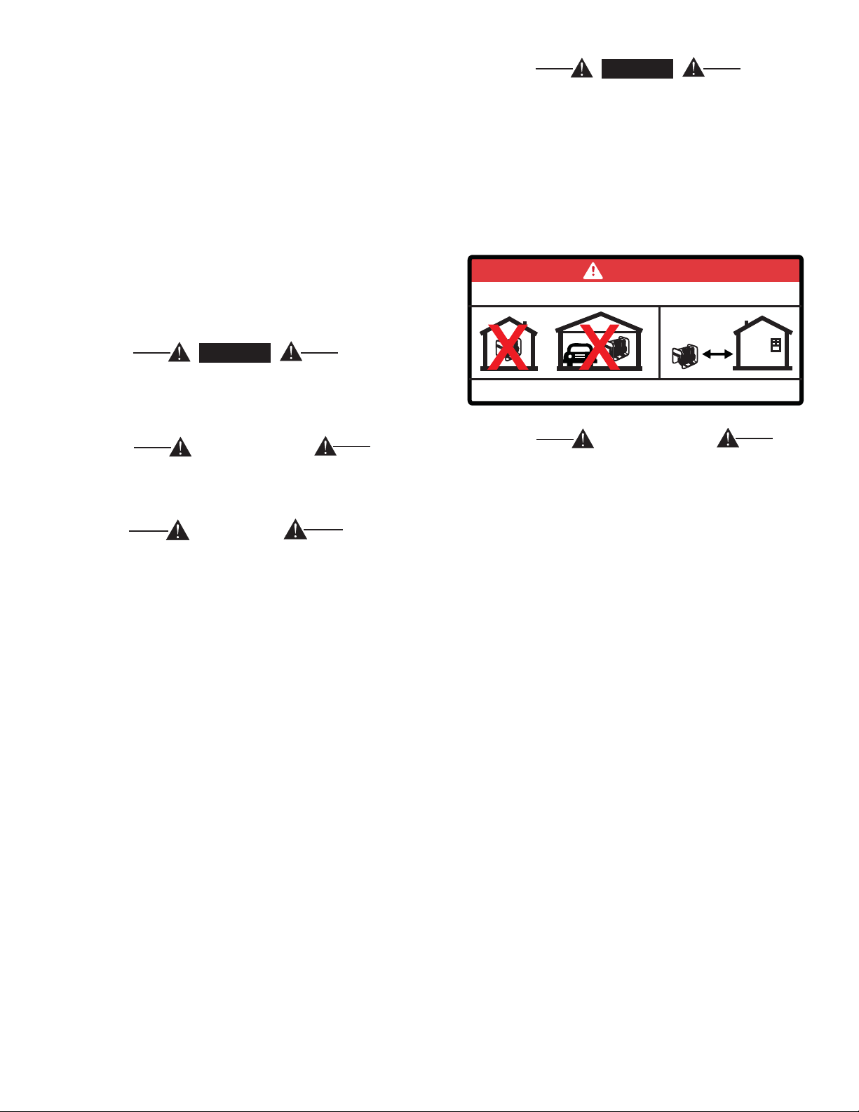
INTRODUCTION
Nous vous remercions d'avoir acheté ce modèle fabriqué par Generac Power
Systems, Inc. Ce modèle est un générateur entraîné par moteur compact, à
haute perfor mance, refroidi à l'air, conçu pour fournir l'alimentation électrique
afin de faire fonctionner les charges électriques lorsqu'aucun réseau électrique
n'est disponible ou à la place du réseau en raison d'une coupure de courant.
LIRE ATTENTIVEMENT CE MANUEL
En cas d'incompréhension d'une partie de ce manuel, contacter le
dépositaire agréé le plus proche pour connaître les procédures de
démarrage, de fonctionnement et d'entretien.
Dans tout ce manuel, et sur les étiquettes et sur les autocollants apposés
sur le générateur, les blocs DANGER, AVERTISSEMENT, ATTENTION et
REMARQUE servent à alerter le personnel d'instructions spéciales au sujet
d'une opération spécifique qui peut s'avérer dangereuse si elle n'est pas
effectuée correctement ou avec précaution. Les respecter attentivement.
Leurs définitions sont les suivantes :
DANGER
DANGER
Utiliser un générateur à l'intérieur VOUS TUERA EN
QUELQUES MINUTES. L'échappement contient du
monoxyde de carbone, un gaz toxique invisible et
inodore.
NE JAMAIS utiliser à l'intérieur ou dans des espaces
partiellement clos tels que les garages. Utiliser
UNIQUEMENT à l'extérieur et loin des fenêtres, portes
ouvertes, ventilations, et dans un espace dans lequel
le gaz d'échappement ne s'accumulera pas de façon
mortelle.
DANGER
Utiliser un générateur à l'intérieur VOUS TUERA EN QUELQUES MINUTES.
L'échappement contient du monoxyde de carbone, un gaz toxique invisible et inodore.
Après ce titre, lire les instructions qui, si elles ne sont
pas strictement respectées, entraîneront des blessures
corporelles graves, y compris la mort et/ou des
dommages aux biens.
AVERTISSEMENT
Après ce titre, lire les instructions qui, si elles ne sont pas
strictement respectées, peuvent entraîner des blessures
corporelles graves et/ou des dommages aux biens.
ATTENTION
Après ce titre, lire les instructions qui, si elles ne sont
pas strictement respectées, pourraient entraîner des
dommages à l'équipement et/ou aux biens.
REMARQUE :
Après ce titre, lire les explications sur lesquelles il est
nécessaire d'insister.
Ces avertissements de sécurité ne peuvent pas éliminer les dangers qu'ils
signalent. Le sens commun et le respect strict des instructions spéciales
lors de l'entretien sont essentiels pour éviter les accidents.
Quatre symboles de sécurité couramment utilisés accompagnent les
blocs DANGER, AVERTISSEMENT et ATTENTION. Chacun indique le type
d'informations suivant :
Ce symbole indique des informations importantes
relatives à la sécurité qui, si elles ne sont pas suivies,
pourraient mettre en danger la sécurité personnelle
et/ou les biens des autres.
Ce symbole indique un risque potentiel d'explosion.
Ce symbole indique un risque potentiel d'incendie.
Ce symbole indique un risque potentiel
d'électrocution.
L'opérateur est responsable de l'utilisation correcte et sûre de
l'équipement. Nous recommandons fortement à l'opérateur de lire ce
manuel et de comprendre complètement toutes les instructions avant
d'utiliser l'équipement.
Nous recommandons également fortement d'apprendre à d'autres
utilisateurs comment correctement démarrer et faire fonctionner
l'unité. Cela les prépare au cas où ils auraient besoin de faire
fonctionner l'équipement pour une urgence.
NE JAMAIS utiliser à l'intérieur ou dans des espaces partiellement clos tels que les garages.
Utiliser UNIQUEMENT à l'extérieur et loin des fenêtres, portes ouvertes et ventilations.
AVERTISSEMENT
Toujours débrancher le fil de bougie et placer le fil
de façon à qu'il n'entre pas en contact avec la bougie
d'allumage afin d'éviter un démarrage accidentel lors
de l'installation, du transport, du réglage ou
des réparations du générateur.
Le générateur produit une tension dangereusement haute qui peut •
entraîner un risque élevé d'électrocution. Éviter le contact avec les fils
nus, les bornes, etc. Ne jamais laisser une personne non qualifiée faire
fonctionner le ou effectuer l'entretien du générateur.
Ne jamais manipuler tout type de cordon ou de dispositif électrique qui •
est dans l'eau, alors que vous êtes pieds nus ou que vos mains ou vos
pieds sont mouillés. Cela entraînera un risque d'électrocution.
Le National Electric Code (Code électrique national) exige que le •
bâti et que les pièces externes électriquement conductrices du
générateur soient correctement reliés à une terre approuvée. Les
codes électriques locaux peuvent également exiger la bonne mise à
la terre du générateur. Consulter un électricien local pour connaître les
exigences de mise à la terre dans la région.
Utiliser un disjoncteur de fuite à la terre dans toute zone humide ou très •
conductrice (telle que le carter protecteur métallique ou l'aciérie).
Ne pas utiliser de cordons électriques usés, nus, effilochés ou •
autrement endommagés avec le générateur.
Faire fonctionner le générateur uniquement sur des surfaces de niveau •
et où il ne sera pas exposé à l'humidité, aux saletés, à la poussière ou
aux vapeurs corrosives excessives.
L'essence est extrêmement • INFLAMMABLE et ses vapeurs sont
EXPLOSIVES. Ne pas produire de fumée, flammes nues, étincelles ou
chaleur à proximité de l'endroit où l'essence est manipulée. Éviter de
renverser de l'essence sur un moteur chaud. Respecter toutes les
lois réglementant le stockage et la manipulation de l'essence.
Ne pas trop remplir le réservoir d'essence. Toujours
laisser de la place pour l'expansion du carburant.
En cas de suremplissage du réservoir, le carburant
peut déborder sur un moteur chaud et entraîner un
INCENDIE ou une EXPLOSION. NE JAMAIS ajouter
de carburant lorsque l'unité fonctionne ou est chaude.
Laisser le moteur complètement refroidir avant
d'ajouter du carburant.
37
Page 40

INSTRUCTIONS IMPORTANTES SUR LA SÉCURITÉ
#/.3)'.%3$%3¡#52)4¡
Système de génératrice portable
CONSERVER CES CONSIGNES – Le fabricant recommande que ces règles relatives au fonctionnement sûr soient
copiées et affichées à proximité du site d'installation de l'unité. Tous les opérateurs et opérateurs potentiels de cet
équipement doivent prendre conscience de la question de la sécurité.
REMARQUE :
DANGER
Ne jamais stocker le générateur avec le réservoir rempli
de carburant étant donné que les vapeurs d'essence
pourraient atteindre une flamme ouverte, des étincelles
ou une veilleuse (comme il y en a sur une chaudière, un
chauffe-eau ou sur un sèche-linge). Cela peut entraîner
un INCENDIE ou une EXPLOSION. Laisser l'unité
complètement refroidir avant le stockage.
Les gaz d'échappement du générateur contiennent
du gaz de monoxyde de carbone MORTEL. Ce gaz
dangereux, s'il est respiré, peut causer des céphalées,
de la fatigue, des vertiges, des vomissements,
une confusion, une attaque, des nausées, des
évanouissements, une perte de conscience ou même
la mort. Faire fonctionner cet équipement uniquement
en plein air, là où l'aération est adéquate.
NE JAMAIS faire fonctionner le générateur à l'intérieur,
dans un garage, à proximité d'une fenêtre ou d'une
porte ouverte, d'une bouche d'aération, dans un vide
sanitaire, dans une autre ouverture ou dans un espace
où le gaz d'échappement pourrait s'accumuler.
Laisser au moins cinq (5) pieds ou plus de jeu sur
tous les côtés du générateur afin de laisse une
aération adaptée pour la sécurité personnelle et éviter
d'endommager l'unité. Ne jamais faire fonctionner
l'unité à l'intérieur de toute pièce ou espace.
Ne jamais démarrer ou arrêter l'unité avec les charges électriques •
branchées aux prises ET avec des dispositifs branchés sous tension.
Démarrer le moteur et le laisser se stabiliser avant de brancher les
charges électriques. Débrancher toutes les charges électriques avant
d'arrêter le générateur.
Ne pas insérer d'objet dans les fentes de refroidissement de l'unité.•
Ne jamais faire fonctionner le générateur : • À l'intérieur ou dans un espace
clos ; sous la pluie ; si des dispositifs électriques branchés surchauffent ;
si la puissance électrique est perdue ; si le moteur ou le générateur fait des
étincelles ; si des flammes ou de la fumée sont détectées alors que l'unité
fonctionne ; si l'unité vibre de façon excessive.
Installer un détecteur d'oxyde de carbone à alimentation par batterie •
à l'intérieur, conformément aux instructions et aux recommandations
du fabricant.
L’échappement du moteur de cet appareil contient des produits
chimiques connus de l’État de Californie comme causant le cancer,
des anomalies congénitales ou d’autres problèmes génésiques.
L’échappement du moteur de cet appareil contient des produits
chimiques connus de l’État de Californie comme causant le cancer,
des anomalies congénitales ou d’autres problèmes génésiques.
AVERTISSEMENT :
AVERTISSEMENT :
Ce générateur est équipé d'un silencieux pare-étincelles. Le
propriétaire / l'opérateur du générateur devra garder le pare-étincelles
en bon état. Dans l'État de Californie, un pare-étincelles est exigé par
la loi (Section 4442 du California Public Resources Code (Code de
ressources publiques de Californie)). Les autres États peuvent avoir des
lois similaires. Les lois fédérales s'appliquent sur les terres fédérales.
Lire attentivement ces RÈGLES DE SÉCURITÉ avant l'installation, le
fonctionnement ou l'entretien de cet équipement. Se familiariser avec ce
manuel et l'unité. Le générateur peut fonctionner en toute sécurité, de
façon efficace et de façon fiable uniquement s'il est correctement installé,
utilisé et entretenu. De nombreux accidents sont dus au non-respect de
règles ou précautions simples et essentielles.
Le fabricant ne peut pas anticiper toutes les situations possibles qui
peuvent impliquer un danger. Les avertissements de ce manuel et figurant
sur les étiquettes et les autocollants apposés sur l'unité ne sont, toutefois,
pas exhaustifs. Si vous suivez une procédure, une méthode de travail ou
une technique de fonctionnement que le fabricant ne recommande pas en
particulier, assurez-vous qu'elle est sans danger pour les autres. S'assurer
que la procédure, la méthode de travail ou la technique de fonctionnement
choisie ne rende pas le générateur dangereux.
DANGER
Malgré la conception sûre de ce générateur, faire
fonctionner ce générateur de façon imprudente,
négliger sa maintenance ou ne pas prendre de
précaution peut entraîner des blessures corporelles
ou la mort. Seulement autoriser les personnes
responsables et compétentes pour faire fonctionner
le ou effectuer la maintenance du générateur.
Ces machines génèrent des tensions potentiellement
mortelles. S'assurer que toutes les étapes sont
suivies pour rendre la machine sûre avant de
commencer à travailler sur le générateur.
Les pièces du générateur tournent et/ou sont
chaudes pendant le fonctionnement. Soyez prudent
si vous êtes à proximité des générateurs en
fonctionnement. Ne pas toucher les surfaces chaudes
comme le pot d'échappement. Cela peut entraîner de
graves brûlures. Laisser refroidir le générateur avant
de le toucher.
DANGERS GÉNÉRAUX
Ne jamais faire fonctionner dans un espace clos ou à l'intérieur.•
Pour des raisons de sécurité, le fabricant recommande que la maintenance •
de cet équipement soit effectuée par un dépositaire agréé.
Les fumées d'échappement du moteur contiennent du monoxyde de •
carbone, qui peut s'avérer MORTEL. Ce gaz dangereux, s'il est respiré
en concentrations suffisantes, peut entraîner une perte de conscience
ou même la mort. Ce système d'échappement doit être cor rectement
entretenu. Ne rien faire qui pourrait rendre le système d'échappement
dangereux ou non conforme aux codes locaux et/ou normes locales.
38
Page 41

INSTRUCTIONS IMPORTANTES SUR LA SÉCURITÉ
#/.3)'.%3$%3¡#52)4¡
Portable Generator System
T enir les mains, les pieds, les vêtements, etc., à distance des courroies •
de transmission, des ventilateurs et d'autres pièces mobiles ou
chaudes. Ne jamais retirer tout protège-ventilateur pendant que l'unité
fonctionne.
Un débit approprié, non obstrué d'air de refroidissement et de •
ventilation est important pour corriger le fonctionnement du générateur.
Ne pas modifier l'installation ou ne pas laisser même un blocage partiel
de l'alimentation de ventilation, étant donné que cela peut sérieusement
affecter le fonctionnement sûr du générateur. Il FAUT faire fonctionner
le générateur à l'extérieur.
Lors du travail sur cet équipement, conserver l'aler te à tout moment. •
Ne jamais travailler sur l'équipement en cas de fatigue physique ou
mentale.
Inspecter régulièrement le générateur et contacter le dépositaire agréé •
le plus proche pour les pièces qui nécessitent une réparation ou un
remplacement.
Avant d'effectuer toute maintenance sur le générateur, débrancher •
ses câbles de batterie afin d'empêcher un démarrage accidentel.
Débrancher le câble de la borne de la batterie signalée par l'inscription
NEGATIVE (Négatif), NEG ou le signe (–) en premier. Rebrancher ce
câble en dernier.
Ne jamais utiliser le générateur ou n'importe laquelle de ses pièces •
comme marche. Monter sur l'unité peut écraser et casser les pièces,
et peut entraîner des conditions de fonctionnement dangereuses suite
à une fuite de gaz d'échappement, une fuite de carburant, une fuite
d'huile, etc.
NE PAS faire fonctionner le générateur sous la pluie.•
DANGERS ÉLECTRIQUES
Tous les générateurs traités par ce manuel produisent des tensions •
électriques dangereuses et peuvent entraîner une électrocution mortelle.
Le réseau électrique délivre des tensions extrêmement élevées et
dangereuses comme le générateur pendant son fonctionnement.
Éviter le contact avec les fils nus, les bornes, les branchements,
etc., pendant le fonctionnement de l'unité. S'assurer que tous les
couvercles, les dispositifs de protection et les barrières sont en place
avant de faire fonctionner le générateur. Si un travail doit être effectué
autour d'une unité en fonctionnement, rester sur une surface isolée et
sèche pour réduire le risque de danger électrique.
Ne jamais manipuler tout type de dispositif électrique qui est dans l'eau, •
alors que vous êtes pieds nus ou que vos mains ou vos pieds sont
mouillés. CELA ENTRAÎNERA UN RISQUE D'ÉLECTROCUTION.
Le National Electric Code (NEC) (Code électrique national) exige que •
le bâti et que les pièces externes électriquement conductrices du
générateur soient correctement reliés à une terre approuvée. Les codes
électriques locaux peuvent également exiger la bonne mise à la terre du
système électrique du générateur.
En cas d'accident causé par électrocution, couper immédiatement la •
source d'alimentation électrique. Si cela est impossible, essayer de
libérer la victime du conducteur sous tension. ÉVITER TOUT CONTACT
DIRECT AVEC LA VICTIME. Utiliser un objet non conducteur, comme
une corde ou une planche, pour libérer la victime du conducteur sous
tension. Si la victime est inconsciente, assurer les premiers secours et
demander une aide médicale immédiate.
Ne jamais porter de bijoux lors du travail sur cet équipement. Les bijoux •
peuvent être conducteurs et entraîner une électrocution ou peuvent se
prendre dans les composants mobiles, entraînant des blessures.
RISQUES D'INCENDIE
Pour la sécurité contre les incendies, le générateur doit être correctement •
utilisé et entretenu. Le fonctionnement doit toujours respecter les
codes, normes, lois et réglementations applicables. Strictement
respecter les codes de construction et électriques locaux, d'État et
nationaux. Conformément aux réglementations, l'Occupational Safety
and Health Administration (OSHA) (Gestion de la sécurité et la santé
au travail) a été établi. S'assurer également que le générateur est utilisé
conformément aux instructions et aux recommandations du fabricant.
Ne pas modifier la construction du générateur ni les commandes, ce
qui pourrait créer une condition de fonctionnement dangereuse.
Garder un extincteur à proximité du générateur à tout moment. Les •
extincteurs portant la mention « ABC » par la National Fire Protection
Association (Association nationale pour la protection contre les
incendies) sont adaptés à une utilisation sur le système électrique de
secours. Garder l'extincteur correctement chargé et se familiariser avec
son utilisation. Si vous avez des questions au sujet des extincteurs,
consultez les pompiers locaux.
L'essence est extrêmement INFLAMMABLE. NE JAMAIS ajouter •
de carburant lorsque l'unité fonctionne ou est chaude. Éviter de
renverser de l'essence sur un moteur chaud. Laisser le moteur/
l'unité complètement refroidir avant d'ajouter du carburant. Ne pas
trop remplir le réservoir d'essence. Toujours laisser de la place pour
l'expansion du carburant. Nettoyer immédiatement toute éclaboussure
de carburant. En cas de suremplissage du réservoir, le carburant peut
déborder sur un moteur chaud et entraîner un INCENDIE. Ne jamais
remplir le réservoir d'essence à l'intérieur.
RISQUES D'EXPLOSION
Ne pas fumer à proximité du générateur. Nettoyer immédiatement toute •
éclaboussure de carburant ou d'huile. S'assurer qu'aucune matière
combustible ne reste sur ou à proximité du générateur , étant donné que
cela peut entraîner un INCENDIE ou une EXPLOSION. Garder l'espace
environnant du générateur propre et sans débris.
L'essence est extrêmement INFLAMMABLE et EXPLOSIVE. •
INDEX DES NORMES
En l'absence de normes, codes, réglementations et lois applicables, les
informations publiées indiquées ci-dessous peuvent servir de directive
pour le fonctionnement de cet équipement. Toujours se reporter à la
dernière révision disponible pour les normes indiquées.
1. NFPA N° 70, NFPA HANDBOOK OF NATIONAL ELECTRIC CODE
(Manuel NFPA du code électrique national).
2. Article X, NA TIONAL BUILDING CODE (Code de construction national),
disponible auprès de l'American Insurance Association, 85 John
Street, New York, N.Y. 10038.
3. AGRICULTURAL WIRING HANDBOOK (Manuel de câblage agricole),
disponible auprès du Food and Energy Council, 909 University
Avenue, Columbia, MO 65201.
4. ASAE EP-3634, INSTALLATION AND MAINTENANCE OF FARM
STANDBY ELECTRICAL SYSTEMS (Installation et maintenance des
systèmes électriques de secours pour les fermes), disponible auprès
de l'American Society of Agricultural Engineers, 2950 Niles Road, St.
Joseph, MI 49085.
5. NFPA N° 30, NFPA AND COMBUSTIBLE LIQUIDS CODE (Code relatif
aux liquides inflammables et combustibles).
39
Page 42

GÉNÉRALITÉS
Section 1 – Généralités
Système de génératrice portable
1.1 DÉBALLAGE
Enlever tous les matériaux d’emballage.•
Enlever la boîte d’accessoires séparée.•
Enlever la génératrice du carton.•
1.1.1 BOÎTE D’ACCESSOIRES
Vérifier le contenu. Si des pièces manquent ou sont endommagées,
chercher un dépositaire autorisé au 1 888 436-3722.
1- Guide du propriétaire•
1- Huile SAE 30•
2- Roues de 7 po•
1- Ensemble manche•
1- Support de manche•
1- Sac de quincaillerie (contenant ce qui suit) :•
2 - Pare-chocs en caoutchouc 7 - Écrous M6
2 - Supports de pare-chocs 1 - Axe
2 - Moyeu 5 - Boulons M6-1 x 40
2 - Rondelles plate M12 2 - Groupilles Fendues
2 - Boulons M6-1.0 x 16
1.2 MONTAGE
La génératrice a besoin d’un certain montage avant de pouvoir être
utilisée. Si des problèmes surviennent quand on monte la génératrice,
appeler la Ligne d’Assistance pour génératrices au 1 888 436-3722.
1.2.1 MONTAGE DU KIT D’ACCESSOIRES
Les roues sont conçues pour augmenter fortement la por tabilité de la
génératrice.
REMARQUE :
Les roues ne sont pas prévues pour être utilisées sur la route.
1. Voir la Figure 1 pour monter les roues comme indiqué.
• Faire glisser l'axe à travers les brides d'axe.
• Faire glisser la moyeu, la roue et la rondelle plate puis
insérer la goupille fendue dans le trou de l’essieu.
• Plier les branches de la goupille vers l’extérieur pour
verrouiller la goupille en place.
2. Voir la Figure 1 pour monter les pare-chocs de roues comme
indiqué.
• Insérer un boulon M6 dans le pare-chocs en caoutchouc
et le bas du suppor t de pare-chocs. Fixer le boulon avec
un écrou M6.
• Installer un boulon M6 dans le cadre de la génératrice et
dans le dessus du support de pare-chocs. Fixer le boulon
avec un écrou M6.
3. Voir la Figure 2 pour monter l’ensemble manche comme
indiqué.
• Insérer le support de manche dans le cadre de la
génératrice et fixer avec deux boulons M6 et deux écrous
M6.
• Aligner les trous de montage du manche avec les trous du
suppor t de manche et fixer avec un boulon M6 et un écrou
M6.
40
Figure 1 – Montage des roues
Figure 2 – Kit de manche
SUPPORT DE MANCHE
3 BOULONS À BRIDE
M6-1.0x40
MONTAGE DU MANCHE
3 ÉCROUS M6-1.0
2.1 CONNAÎTRE LA GÉNÉRATRICE
Lire le guide du propriétaire et les règles de sécurité avant d’utiliser
cette génératrice.
Comparer la génératrice aux figures 3 à 6 pour se familiariser avec
l’emplacement des commandes et des réglages. Conserver ce guide pour
utilisation ultérieure.
1. 120 Volts CA, 20 A, Prise double – Fournit l’alimentation électrique
pour le fonctionnement de charges de moteur, d'éclairage, d’outils,
d’appareils électriques de 120 volts CA, 20 A, monophasés, 60Hz.
2. Disjoncteurs (c.a.) – Chaque prise est fournie avec un disjoncteur
de type « pousser pour réenclencher » de 13,5 A pour protéger le
générateur contre les surcharges électriques.
3. Filtre à air – Filtre l’air quand il entre dans le moteur.
4. Bouton de volet d’air – Utilisé quand on fait démarrer un moteur froid.
5. Réservoir de carburant – Le réservoir contient 4 gallons US de
carburant.
6. Borne de mise à la terre – Mettre la génératrice à la ter re à une
masse à la terre approuvée ici. Voir « mise à la terre de la génératrice
» pour détails.
Page 43

Section 2 – Fonctionnement
FONCTIONNEMENT
Système de génératrice portable
7. Bouton Marche/Arrêt – Commande le fonctionnement de la
génératrice.
8. Silencieux – Rend le moteur moins bruyant.
9. Rend le moteur moins bruyant – Pivote et se rétracte pour ranger.
10. Bouchon d’essence – Emplacement de remplissage de carburant.
11. Jauge de carburant – Indique le niveau de carburant dans le réservoir.
12. Vérification/R emplissage d’huile – Vérifier et remplir d’huile ici.
13. Lanceur – Utiliser pour faire démarrer le moteur manuellement.
14. Arrêt du carburant – Valve entre le réservoir de carburant et le
carburateur.
15. Bouchon de vidange de l’huile – Utilisé pour vidanger l’huile.
16. Pare-étincelles – Réduit les risques d’incendie en contenant les
étincelles.
17. Soupape de sécurité – Passe les vapeurs d’essence dans le réservoir
á charbon actif.
18. Réservoir á charbon actif – Absorbe les vapeurs du réservoir
d’essence.
19. Tuyau de récupération – Installé entre les éléments 17 et 18.
Figure 3 - Panneau de commande
7
21
Figure 5 - Commandes de la génératrice
7
15
12
Figure 6 - Commandes de la génératrice
17
19
16
8
6
Figure 4 - Commandes de la génératrice
6
18
41
19
Page 44

Section 2 – Fonctionnement
FONCTIONNEMENT
Système de génératrice portable
2.2 CORDONS ÉLECTRIQUES ET FICHES DE
BRANCHEMENT
2.2.1 120 VAC, 20 A, PRISE DOUBLE
C’est une prise 120 volts protégée contre les surcharges par un
disjoncteur « pousser pour réenclencher » de 13.5 A (Figure 6). 13.5 A
de courant peuvent être tirées de chaque douille, la puissance totale doit
cependant être gardée dans le nominal de la plaque de données. N’utiliser
que des cordons électriques à 3 fils, à la terre, bien isolés, de haute qualité
avec un nominal de 125 volts à 20 A (ou plus).
2.3 MODE D’EMPLOI DE LA GÉNÉRATRICE
Si des problèmes surviennent quand on utilise la génératrice, appeler la
Ligne d’Assistance des génératrices au 1 888 436-3722.
Utiliser un générateur à l'intérieur VOUS TUERA EN
QUELQUES MINUTES. L'échappement contient du
monoxyde de carbone, un gaz toxique invisible et
inodore.
NE JAMAIS utiliser à l'intérieur ou dans des espaces
partiellement clos tels que les garages. Utiliser
UNIQUEMENT à l'extérieur et loin des fenêtres, portes
ouvertes, ventilations, et dans un espace dans lequel
le gaz d'échappement ne s'accumulera pas de façon
mortelle.
Utiliser un générateur à l'intérieur VOUS TUERA EN QUELQUES MINUTES.
L'échappement contient du monoxyde de carbone, un gaz toxique invisible et inodore.
NE JAMAIS utiliser à l'intérieur ou dans des espaces partiellement clos tels que les garages.
Utiliser UNIQUEMENT à l'extérieur et loin des fenêtres, portes ouvertes et ventilations.
2.3.1 MISE À LA TERRE DE LA GÉNÉRATRICE
Le code national de l'électricité requiert que le cadre et les pièces
externes conductrices électriques de la génératrice soient connectés
correctement à une masse à la terre approuvée (Figure 7). Le code
local d'électricité peut aussi exiger la mise à la terre correcte de la
génératrice. Pour cette raison, connecter un fil torsadé en cuivre N° 10
AWG (American Wire Gauge) à la borne à la terre et à une tige de mise
à la terre en cuivre ou laiton (électrode) plantée dans la terre fournit une
protection adéquate contre les décharges électriques. Les codes locaux
peuvent cependant être très différents. Voir un électricien local pour les
exigences de mise à la terre dans la région.
Une bonne mise à la terre de la génératrice aidera à empêcher des
décharges électriques dans le cas d’une mise à la masse défectueuse
dans la génératrice ou dans des appareils électriques branchés. Une mise
à la terre correcte aide aussi à dissiper l’électricité statique qui s’accumule
souvent dans des appareils non mis à la masse.
42
DANGER
DANGER
Figure 7 - Mise à la terre de la génératrice
2.3.2 BRANCHEMENT DES CHARGES ÉLECTRIQUES
NE PAS brancher des charges de 240 volts à des prises de 120 volts. NE
PAS brancher des charges triphasées à la génératrice. NE PAS brancher
des charges de 50 Hz à la génératrice.
Donner quelques minutes au moteur pour se stabiliser et chauffer •
après sa mise en route.
Brancher et mettre en route les charges électriques 60 Hz, monophasées, •
120 ou 240 volts CA.
Faire la somme de la puissance nominale (ou ampères) de toutes •
les charges qui doivent être branchées en même temps. Ce total ne
doit pas dépasser (a) la capacité nominale puissance/intensité de la
génératrice ou (c) le nominal du disjoncteur de la prise fournissant le
courant. Voir « Ne pas surcharger la génératrice ».
2.4 NE PAS SURCHARGER LA GÉNÉRATRICE
Surcharger une génératrice au-delà de sa capacité de puissance nominale peut
causer des dommages à la génératrice et aux appareils électriques branchés.
Observer ce qui suit pour empêcher la surcharge de l'appareil :
Faire la somme de la puissance de tous les appareils électriques •
branchés en même temps. Cette somme NE doit PAS être supérieure
à la capacité de puissance de la génératrice.
On trouve la puissance nominale des lumières sur les ampoules •
électriques. On peut normalement trouver la puissance nominale des
outils, appareils et moteurs sur une étiquette ou décalcomanie de
données fixée sur l'appareil.
Si l’appareil, l’outil ou le moteur ne donne pas la puissance, multiplier •
les volts par le nominal d’intensité pour déterminer la puissance (volts
x ampères = watts).
Certains moteurs électriques, comme les moteurs à induction, ont •
besoin de trois fois plus de watts pour se mettre en route que pour
fonctionner. Cette poussée de puissance ne dure que quelques
secondes quand on fait démarrer ce type de moteur. Ne pas oublier de
tenir compte de cette forte puissance de démar rage quand on choisit
les appareils électriques à brancher à la génératrice.
1. Évaluer le nombre de watts nécessaires pour faire démarrer le plus
gros moteur.
2. Ajouter à ce chiffre les watts de fonctionnement de toutes les
charges branchées.
Le guide de référence de puissance est fourni pour aider à déterminer le
nombre d’appareils que la génératrice peut alimenter à la fois.
REMARQUE :
T ous les chiffres sont approximatifs. V oir l’étiquette des données
sur l’appareil pour les besoins de puissance.
Page 45

Hu il e sy nt hé tiq ue
5W -3 0
SAE 3 0
MISE EN GARDE
DANGER
Section 2 – Fonctionnement
FONCTIONNEMENT
Système de génératrice portable
2.5 GUIDE DE RÉFÉRENCE DE PUISSANCE
Appareil . . . . . . . . . . . . . . . . . . . . . . . . . . . . . . . Watts (en marche)
*Climatiseur (12 000 Btu). . . . . . . . . . . . . . . . . . . . . . . . . . . . . 1700
*Climatiseur (24 000 Btu). . . . . . . . . . . . . . . . . . . . . . . . . . . . . 3800
*Climatiseur (40 000 Btu). . . . . . . . . . . . . . . . . . . . . . . . . . . . . 6000
Chargeur de batterie (20 A). . . . . . . . . . . . . . . . . . . . . . . . . . . . . 500
Ponceuse à bande (3 po) . . . . . . . . . . . . . . . . . . . . . . . . . . . . . 1000
Scie à chaîne . . . . . . . . . . . . . . . . . . . . . . . . . . . . . . . . . . . . . . 1200
Scie circulaire (6-1/2 po) . . . . . . . . . . . . . . . . . . . . . . . . 800 à 1000
*Sécheuse (Électrique). . . . . . . . . . . . . . . . . . . . . . . . . . . . . . . 5750
*Sécheuse (Gaz) . . . . . . . . . . . . . . . . . . . . . . . . . . . . . . . . . . . . 700
*Machine à laver le linge . . . . . . . . . . . . . . . . . . . . . . . . . . . . . 1150
Cafetière. . . . . . . . . . . . . . . . . . . . . . . . . . . . . . . . . . . . . . . . . . 1750
*Compresseur (1 CV). . . . . . . . . . . . . . . . . . . . . . . . . . . . . . . . 2000
*Compresseur (3/4 CV) . . . . . . . . . . . . . . . . . . . . . . . . . . . . . . 1800
*Compresseur (1/2 CV) . . . . . . . . . . . . . . . . . . . . . . . . . . . . . . 1400
Fer à friser . . . . . . . . . . . . . . . . . . . . . . . . . . . . . . . . . . . . . . . . . 700
*Déshumidificateur. . . . . . . . . . . . . . . . . . . . . . . . . . . . . . . . . . . 650
Ponceuse à disque (9 po). . . . . . . . . . . . . . . . . . . . . . . . . . . . . 1200
Coupe-bordure . . . . . . . . . . . . . . . . . . . . . . . . . . . . . . . . . . . . . . 500
Couverture électrique . . . . . . . . . . . . . . . . . . . . . . . . . . . . . . . . . 400
Pistolet goujonneur électrique. . . . . . . . . . . . . . . . . . . . . . . . . . 1200
Cuisinière électrique (par élément) . . . . . . . . . . . . . . . . . . . . . . 1500
Poêle électrique . . . . . . . . . . . . . . . . . . . . . . . . . . . . . . . . . . . . 1250
*Congélateur . . . . . . . . . . . . . . . . . . . . . . . . . . . . . . . . . . . . . . ..700
*Ventilateur d’appareil de chauffage (3/5 CV) . . . . . . . . . . . . . . . 875
*Ouvre-porte de garage . . . . . . . . . . . . . . . . . . . . . . . . . .500 to 750
Sèche-cheveux. . . . . . . . . . . . . . . . . . . . . . . . . . . . . . . . . . . . . 1200
2.6 AVANT LA MISE EN MARCHE DE LA GÉNÉRATRICE
Avant d’utiliser la génératrice, il faut ajouter de l’huile et de l’essence
comme suit :
2.6.1 AJOUT DE L’HUILE DE MOTEUR
L’huile doit être au moins American Petroleum Institute (API) Service Class
SJ, SL ou mieux. N’utiliser aucun additif spécial. Choisir la viscosité de
l’huile suivant la température de fonctionnement anticipée (voir aussi le
tableau).
Au dessus de 4 °C (40 °F), utiliser SAE 30•
En dessous de 4 °C (40 °F), et jusqu’à -12 °C (10° F) utiliser 10W-30•
Au dessous de -12 °C (10° F), utiliser de l’huile synthétique 5W-30•
SAE 30
10W-30
Huile synthétique
5W-30
Gamme de température d’utilisation anticipée
Perceuse . . . . . . . . . . . . . . . . . . . . . . . . . . . . . . . . . . . . 250 à 1100
Taille-haies . . . . . . . . . . . . . . . . . . . . . . . . . . . . . . . . . . . . . . . . . 450
Clé à chocs . . . . . . . . . . . . . . . . . . . . . . . . . . . . . . . . . . . . . . . . 500
Fer . . . . . . . . . . . . . . . . . . . . . . . . . . . . . . . . . . . . . . . . . . . . . . 1200
*Pompe à jet . . . . . . . . . . . . . . . . . . . . . . . . . . . . . . . . . . . . . . . 800
Tondeuse à gazon. . . . . . . . . . . . . . . . . . . . . . . . . . . . . . . . . . . 1200
Ampoule. . . . . . . . . . . . . . . . . . . . . . . . . . . . . . . . . . . . . . . . . . . 100
Four à micro-ondes . . . . . . . . . . . . . . . . . . . . . . . . . . . . 700 à 1000
*Réfrigérant à lait . . . . . . . . . . . . . . . . . . . . . . . . . . . . . . . . . . 1100
Brûleur à mazout sur appareil de chauffage. . . . . . . . . . . . . . . . . 300
Radiateur électrique portatif à mazout (140 000 Btu) . . . . . . . . . 400
Radiateur électrique portatif à mazout (85 000 Btu) . . . . . . . . . . 225
Radiateur électrique portatif à mazout (30 000 Btu) . . . . . . . . . . 150
*Pistolet à peinture, sans air comprimé (1/3 CV) . . . . . . . . . . . . 600
Pistolet à peinture, sans air comprimé (à main) . . . . . . . . . . . . . 150
Radio . . . . . . . . . . . . . . . . . . . . . . . . . . . . . . . . . . . . . . . . . 50 à 200
*Réfrigérateur. . . . . . . . . . . . . . . . . . . . . . . . . . . . . . . . . . . . . . . 700
Mijoteuse . . . . . . . . . . . . . . . . . . . . . . . . . . . . . . . . . . . . . . . . . . 200
*Pompe submersible (1-1/2 CV). . . . . . . . . . . . . . . . . . . . . . . . 2800
*Pompe submersible (1 CV). . . . . . . . . . . . . . . . . . . . . . . . . . . 2000
*Pompe submersible (1/2 CV) . . . . . . . . . . . . . . . . . . . . . . . . . 1500
*Pompe de puisard. . . . . . . . . . . . . . . . . . . . . . . . . . . . . 800 à 1050
*Table de sciage (10 po) . . . . . . . . . . . . . . . . . . . . . . . 1750 à 2000
Télévision . . . . . . . . . . . . . . . . . . . . . . . . . . . . . . . . . . . . . 200 à 500
Grille-pain. . . . . . . . . . . . . . . . . . . . . . . . . . . . . . . . . . . 1000 à 1650
Tondeuse à fil. . . . . . . . . . . . . . . . . . . . . . . . . . . . . . . . . . . . . . . 500
* Le démarrage de ces appareils nécessitera trois fois la puissance
indiquée exprimée en watts.
Toute tentative de mise en route du moteur avant qu’il ait
été correctement maintenu avec l’huile recommandée
peut entraîner une panne de moteur.
Mettre la génératrice sur une surface plane.•
Nettoyer autour du bouchon d’huile et enlever le bouchon et la jauge.•
Nettoyer la jauge.•
Remplir lentement le moteur d’huile (au travers de l’ouverture à huile) •
jusqu’à ce qu’elle atteigne le bas du filetage de la jauge graduée.
S’arrêter de remplir de temps en temps pour vérifier le niveau d’huile.
Faire attention de ne pas trop remplir.
Remettre le bouchon et serrer avec les doigts.•
À partir de maintenant, vérifier chaque fois le niveau d’huile du moteur •
avant de mettre en route.
2.6.2 AJOUT DE L’ESSENCE
Ne jamais remplir le réservoir à l’intérieur. Ne jamais
remplir le réservoir quand le moteur est en route ou
chaud. Attendre que le moteur soit complètement refroidi
avant de remplir le réservoir. Éviter de renverser de
l’essence sur un moteur CHAUD. NE PAS allumer de
cigarette et ne pas fumer quand on remplit le réservoir.
L’essence est extrêmement INFLAMMABLE et ses
vapeurs sont EXPLOSIVES.
43
Page 46

MISE EN GARDE
AVERTISSEMENT
Section 2 – Fonctionnement
FONCTIONNEMENT
Système de génératrice portable
Ne pas trop remplir le réservoir de carburant.
Toujours laisser de l’espace pour l’expansion du
carburant. Si le réservoir est trop rempli, le carburant
peut déborder sur un moteur CHAUD et causer un
INCENDIE ou une EXPLOSION.
Utiliser de l’essence ordinaire SANS PLOMB dans le moteur de la •
génératrice. Ne pas utiliser d’essence ayant plus de 10 % d’éthanol
ajouté et ne jamais utiliser d’essence E85. Ne pas mélanger l’huile
avec l’essence.
Nettoyer autour du bouchon, enlever le bouchon.•
Ajouter doucement de l’essence ordinaire sans plomb au réservoir. •
Remplir jusqu’au fond du filtre à grille. Attention de ne pas trop
remplir (Figure 8).
Mettre le bouchon de carburant et essuyer toute l’essence renversée. •
Figure 8 - Réservoir de carburant
Mettre le levier de l’ÈTRANGLEUR du moteur sur la position •
DÉMARRAGE.
Pour mettre le moteur en route, bien attraper le lanceur et tirer •
doucement jusqu’à ce qu’on sente une résistance accrue. Tirer
rapidement vers le haut et au loin.
REMARQUE :
Si le moteur se déclenche mais ne continue pas à fonctionner,
déplacer le levier de l’étrangleur sur START et recommencer en
suivant les instructions de mise en route.
Schéma 9 - Soupape d’arrêt
LEVIER
ÉTRANGLEUR
IMPORTANT : Il est important d’éviter des parties du système de
carburant comme le carburateur, le tuyau de carburant ou le réservoir se
gomment quand l’appareil est rangé. Les carburants contenant de l’alcool
(appelés gazohol, éthanol ou méthanol) peuvent attirer l’humidité, ce qui
amène à la séparation et à la formation d’acides pendant le rangement.
Les gaz acides peuvent endommager le système de carburant d’un
moteur pendant qu’il est rangé. Pour éviter des problèmes avec le moteur,
le système de carburant doit être vidé avant de ranger l’appareil pendant
30 jours ou plus. Voir la section « Rangement ». Ne jamais utiliser de
produits de nettoyage de carburateur ou de moteur dans le réservoir de
carburant, car ils peuvent causer des dommages permanents.
2.7 DÉMARRAGE DU MOTEUR
Ne jamais mettre en route ou arrêter le moteur avec
des appareils électriques branchés dans les prises
ET avec les appareils en marche.
Débrancher toutes les charges électriques des prises de l’appareil •
avant de mettre le moteur en route.
S’assurer que l’appareil est à niveau.•
Mettre la soupape d’arrêt sur la position ON (Marche) (Schéma 9).•
Mettre le bouton ON/OFF (Marche/Arrêt) sur ON (Figure 10).•
44
NE PAS REMPLIR AUDESSUS
DE LA LÉVRE
POIGNÉE
DE RAPPEL
INTERRUPTEUR
ON/OFF (MARCHE/ARRÊT)
Figura 10 - Position de létrangleur
Position de létrangleur
IMPORTANT : Ne pas surcharger la génératrice. Ne pas surcharger non
plus les prises de panneau individuelles. Ces prises sont protégées contre
les surcharges par des disjoncteurs du type « pousser et réenclencher
». Si le nominal d’intensité d’un disjoncteur est dépassé, ce disjoncteur
s’ouvre et le débit électrique à cette prise est perdu. Lire attentivement «
Ne pas surcharger la génératrice »
Page 47

MISE EN GARDE
Section 3 — Entretien
ENTRETIEN
Système de génératrice portable
2.8 ARRÊT DU MOTEUR
Éteindre toutes les charges puis les débrancher des prises du panneau •
de la génératrice. Ne jamais mettre en route ou arrêter le moteur avec
des appareils électriques branchés et en marche.
Laisser tourner le moteur sans charge pendant quelques minutes pour •
stabiliser les températures internes du moteur et de la génératrice.
Mettre l’interrupteur ON/OFF (marche/arrêt) sur OFF (marche).•
Fermer la vanne de carburant.•
2.9 SYSTÈME D'ARRÊT EN CAS DE FAIBLE NIVEAU D’HUILE
Le moteur est équipé d’un capteur de faible niveau d’huile qui coupe le
moteur automatiquement quand le niveau d’huile tombe au dessous d’un
niveau spécifié. Si le moteur s’arrête de lui-même et si le réservoir à
carburant a assez d'essence, vérifier le niveau d’huile dans le moteur.
2.9.1 DÉTECTION DE FAIBLE NIVEAU D’HUILE
Si le système détecte un niveau d’huile faible pendant le fonctionnement,
le moteur s’arrête. Le moteur de fonctionnera pas tant que le réservoir
d’huile n’a pas été rempli au niveau correct.
3.1 CALENDRIER D’ENTRETIEN
Suivre les intervalles du calendrier. Un entretien plus fréquent est requis
quand l’appareil est utilisé dans les conditions défavorables notées
ci-dessous.
Vérifier le niveau d’huile À chaque utilisation
Changement d’huile + *Chaque saison
Vérifier le jeu de soupape ***Chaque saison
Entretien du filtre à air **Chaque saison
Remettre la bougie Chaque saison
+ Changer l’huile après les 20 premières heures de fonctionnement puis à chaque
saison.
* Changer l’huile tous les mois lors du fonctionnement sous une charge lourde
ou à des températures élevées.
** Nettoyer plus souvent quand le fonctionnement est dans des conditions
sales et poussiéreuses. Remplacer les pièces de filtre à air qui ne
peuvent pas être nettoyées correctement.
*** Vérifier le jeu de soupape. Si nécessaire régler après les 50
premières heures de fonctionnement et toutes les 100 heures
ensuite.
3.2.2 SPÉCIFICATIONS DU MOTEUR
Cylindrée ...................................................................................208 cc
Type de bougie ...................................................F6TC ou NGK BPR4ES
Écartement des électrodes de bougie ......0,028-0,031 po ou (0,70-0,80
mm)
Contenance du réservoir d’essence ...................15,14 L (4 gallons U.S.)
Type d’huile ...........................................................................................
Voir le tableau dans la section « Avant
de mettre la génératrice en route »
Contenance du réservoir d’huile ..............................0,6 L (0,634 pintes)
Temps de fonctionnement ...............................12,5 heures à 1/2 charge
Émission certifiée Classe II*
* Le fabricant du moteur doit garantir le système de contrôle d’émission
pendant une période de deux ans. Cette couverture de garantie est en
plus de la garantie fournie par Generac et peut couvrir le moteur même
si la garantie de Generac ne le fait pas
3.3 RECOMMANDATIONS GÉNÉRALES
La garantie de la génératrice ne couvre pas les articles qui ont été soumis
aux abus de l'utilisateur ou à sa négligence. Pour recevoir la pleine valeur
de la garantie, l’opérateur doit maintenir la génératrice de la façon indiquée
dans ce guide.
Il faut faire certains réglages de temps en temps pour entretenir
correctement la génératrice.
Il faut faire tous les réglages de la section entretien de ce guide au moins une
fois par saison. Respecter les exigences du « Calendrier d'entretien ».
REMARQUE :
Changer la bougie et le filtre à air une fois par an. Une nouvelle
bougie et un filtre à air propre assurent un mélange correct
air-carburant et aide le moteur à mieux tourner et à durer plus
longtemps.
3.3.1 ENTRETIEN DE LA GÉNÉRATRICE
L’entretien de la génératrice consiste à garder l’appareil propre et sec.
Utiliser et ranger l’appareil dans un environnement propre et sec où
il ne sera pas exposé à un excès de poussière, de saleté, d’humidité
ou de vapeurs corrosives. Les fentes de refroidissement d’air dans la
génératrice ne doivent jamais être obstruées par la neige, les feuilles ou
tout autre matériau.
Vérifier souvent la propreté de la génératrice et la nettoyer quand on peut
voir de la poussière, de la saleté, de l’huile, de l’humidité et d’autres
substances sur sa surface extérieure.
3.2 SPÉCIFICATIONS DU PRODUIT
3.2.1 SPÉCIFICATIONS DE LA GÉNÉRATRICE
Puissance nominal ................................................................3,25 kW**
Puissance de pointe ..................................................................3,75 kW
Nominal de tension CA .....................................................................120
Courant nominal .......................................................................27 A**
Fréquence nominale ............................................... 60 Hz @ 3600 RPM
Phase ..................................................................................Monophasé
** La puissance maximale est soumise à, et limitée par, des facteurs
comme contenu Btu du carburant, la température ambiante, l’altitude,
la condition du moteur, etc. La puissance maximale diminue d’environ
3,5 % par 1000 pieds au dessus du niveau de la mer et diminue
d'environ 1 % par 6°C (10 °F) au dessus d’une température ambiante
de 16 °C (60 ° F).
Ne jamais insérer objets ou outils au travers des
fentes de refroidissement par air, même si le moteur
ne tourne pas.
REMARQUE :
NE PAS nettoyer la génératrice avec un tuyau de jardin. L’eau
peut entrer dans le système de carburant du moteur et causer
des problèmes. De plus, si l’eau entre dans la génératrice par
les fentes de refroidissement par air, de l’eau peut stagner dans
les vides et fissures du rotor et de l’isolant du bobinage du stator.
L’accumulation d’eau et de saleté sur le bobinage interne de la
génératrice diminuera éventuellement la résistance d’isolation de
ces bobinages.
45
Page 48

DANGER
MISE EN GARDE
Section 3 — Entretien
ENTRETIEN
Système de génératrice portable
3.3.2 NETTOYAGE DE LA GÉNÉRATRICE
Utiliser un chiffon humide pour essuyer l’extérieur des surfaces.•
On peut utiliser une brosse douce pour enlever la saleté ou l’huile, etc. •
agglomérée.
On peut utiliser un aspirateur pour enlever les débris et la saleté non •
collés.
On peut utiliser de l’air comprimé à faible pression (ne pas dépasser •
25 psi) pour expulser la saleté. Inspecter les fentes de refroidissement
par air et les ouvertures de la génératrice. Il faut garder ces ouvertures
propres et sans obstructions.
3.3.3 ENTRETIEN DU MOTEUR
Toujours débrancher le fil de bougie de la bougie
d’allumage et rester à distance de celui-ci en cas de
travail sur le générateur.
3.3.4 VÉRIFICATION DU NIVEAU D’HUILE
Voir la section « Avant de mettre la génératrice en route » pour informations
sur la vérification du niveau d’huile. Il faut vérifier le niveau d’huile avant
chaque utilisation ou au moins toutes les huit heures de fonctionnement.
Garder le niveau d’huile (Figure 11).
Figure 11 - Vérification/Vidange et remplissage d’huile
Utiliser les instructions suivantes pour changer l’huile quand le moteur
est toujours tiède.
Nettoyer la zone autour du bouchon de vidange d’huile.•
Enlever le bouchon de vidange du moteur et le bouchon de remplissage •
d’huile pour vidanger complètement l’huile dans un récipient
approprié.
Une fois l’huile complètement vidangée, mettre le bouchon de vidange •
et bien serrer.
Remplir le moteur avec l’huile recommandée. (voir la section « Avant •
le démarrage du générateur » pour les recommandations sur l’huile à
utiliser).
Essuyer toute l’huile renversée.•
Jeter l’huile usagée dans un centre de ramassage approprié.•
3.3.6 REMPLACEMENT DE LA BOUGIE
Utiliser une bougie F6TC ou une NGK BPR4ES. Remplacer la bougie une
fois par an. Cela contribuera à faire mieux démarrer et tourner le moteur.
1. Arrêter le moteur et tirer le fil de bougie de la bougie.
2. Nettoyer autour de la bougie et l’enlever de la tête de cylindre.
3. Régler l’écartement à 0,70-0,80 mm (0,028-0,031 po). Placer la
bougie avec l’écartement cor rect dans la tête de cylindre et serrer à
15 pi/lb. (Figure 12).
Figure 12 - Écartement des électrodes de bougie
Vidange
Vérification et
remplissage d’huile
3.3.5 CHANGEMENT DE L’HUILE
Changer l’huile après les huit premières heures de fonctionnement puis
toutes les 20 heures après cela. Changer l’huile plus souvent si on utilise
l’appareil dans des conditions de saleté et de poussière ou quand il fait
extrêmement chaud.
L’huile chaude peut causer des brûlures. Laisser
refroidir le moteur avant de vidanger l’huile. Éviter
d’exposer la peau à l’huile usagée d’une façon
prolongée ou répétée. Laver soigneusement au savon
les zones exposées.
46
3.3.7 PARE-ÉTINCELLES
1. Éteindre la génératrice et laisser refroidir complètement le moteur et
le silencieux avant de toucher le pare-étincelles (situé à l’arrière du
silencieux).
2. Enlever la pince et le pare-étincelles.
3. Nettoyer le pare-étincelles avec une petite brosse métallique.
4. Remplacer le pare-étincelles s’il est endommagé.
5. L’installation du pare-étincelles est le contraire de son enlèvement.
3.4 ENTRETIEN DU FILTRE À AIR
Le moteur ne fonctionne pas correctement et peut être endommagé si on
utilise un filtre à air sale. Nettoyer le filtre à air une fois par an (Figure 13).
Nettoyer et remplacer plus souvent quand on utilise l’appareil dans des
conditions poussiéreuses.
Enlever le couvercle du filtre à air.•
Laver à l’eau savonneuse. Presser le filtre dans un chiffon propre (NE •
PAS TORDRE).
Nettoyer le couvercle du filtre à air avant de le remettre.•
Page 49

DANGER
DANGER
MISE EN GARDE
DANGER
Section 3 — Entretien
ENTRETIEN
Système de génératrice portable
REMARQUE :
Pour contacter un filtre à air neuf, contacter le centre de
réparations autorisé le plus proche en appelant 1 888 436-
3722.
Figure 13 - Filtre à air
Couvercle du
nettoyeur d’air
Filtre à air
3.5 JEU DE SOUPAPE
Admission — 0,10 ± 0,02 mm (froid), (0,003 po ± 0,005 po) •
Échappement — 0,15 ± 0,02 mm (froid) (0,005 po ± 0,007 po)•
Après les 50 premières heures de fonctionnement, vérifier le jeu de
soupape dans le moteur et régler si nécessaire.
Important: Si l’on n’est pas à l’aise pour faire cette procédure ou si les
outils appropriés ne sont pas disponibles, apporter la génératrice au
centre de réparations le plus proche pour faire régler le jeu de soupape.
C’est une étape très importante qui assure la vie utile la plus longue
possible du moteur.
3.6 GÉNÉRALITÉS
Il faut mettre en route la génératrice au moins une fois tous les sept jours et
la laisser tourner pendant au moins 30 minutes. Si cela n’est pas possible
et s'il faut ranger l’appareil pendant plus de 30 jours, utiliser les informations
suivantes comme guide à la préparation pour le rangement.
NE JAMAIS ranger le moteur avec du carburant dans
le réservoir à l’intérieur , dans un endroit mal aéré où
les émanations peuvent atteindre une flamme nue, une
étincelle ou une veilleuse comme dans le cas d’un
système de chauffage, d'un chauffe-eau, d'un sèchelinge ou d'un autre appareil à gaz.
3.7 RANGEMENT À LONG TERME
Il est important d’empêcher que se gomment les pièces essentielles du
système de carburant comme le carburateur, le tuyau de carburant ou le
réservoir quand l’appareil est rangé. L’expérience montre également que
les carburants à alcool (appelés gazohol, éthanol ou méthanol) peuvent attirer
l’humidité, ce qui amène à la séparation et à la formation d’acides pendant
le rangement. Les gaz acides peuvent endommager le système de carburant
d’un moteur pendant qu’il est rangé.
Pour éviter des problèmes avec le moteur, le système de carburant doit être
vidé avant de ranger l’appareil pendant 30 jours ou plus comme suit
Enlever toute l’essence du réservoir.•
Vidanger le carburant à l’extérieur, dans un récipient
approuvé et loin d’une flamme nue. S’assurer que le
moteur est froid. Ne pas fumer.
Mettre en route et faire tourner le moteur jusqu’à ce qu’il s’arrête par •
manque de carburant.
Pendant que le moteur est toujours tiède, vidanger l’huile du carter. •
Remplir avec le type d’huile recommandé.
Enlever les bougies et verser environ ½ once (15 ml) d’huile de moteur •
dans les cylindres. Couvrir le trou de la bougie avec un chiffon. Tirer
le lanceur une fois ou deux pour lubrifier les segments de piston et
l’alésage du cylindre.
Éviter la vaporisation des trous de bougies quand on
lance le moteur.
Installer et serrer les bougies. Ne pas brancher les fils de bougies.•
Nettoyer les surfaces extérieures de la génératrice. Vérifier que les •
fentes de refroidissement par air et les ouvertures sur la génératrice
sont ouvertes et non obstruées.
Ranger l’appareil dans un endroit sec et propre.•
3.8 AUTRES CONSEILS SUR LE RANGEMENT
Ne pas stocker de l’essence d’une saison à l’autre.•
Remplacer le bidon d’essence s’il commence à se rouiller. Rouille et/•
ou saleté dans l’essence causeront des problèmes avec le carburateur
et le système de carburant.
Si possible, ranger l’appareil à l’intérieur et le couvrir pour le protéger •
de la poussière et de la saleté. NE PAS OUBLIER DE VIDER LE
RÉSERVOIR DE CARBURANT.
S’il n'est pas pratique de vider le réservoir de carburant et si l’appareil •
doit être rangé pendant un certain temps, ajouter un stabilisateur de
carburant du commerce à l’essence pour augmenter la vie utile de
l’essence.
Couvrir l’appareil de façon appropriée qui ne retienne pas l’humidité.•
NE JAMAIS couvrir la génératrice tant que le moteur
et l’échappement sont encore chauds.
47
Page 50

DÉPANNAGE
Section 4 — Dépannage
Système de génératrice portable
4.1 GUIDE DE RÉPARATIONS
PROBLÈME CAUSE CORRECTION
Le moteur tourne mais aucune
sortie CA n’est disponible.
1. Le disjoncteur est ouvert.
2. Mauvaise connexion ou cordon électrique
défectueux.
3. L’appareil branché ne fonctionne pas.
4. Problème avec la génératrice.
1. Remettre le disjoncteur.
2. Vérifier et réparer.
3. Brancher un autre appareil en bon état.
4. Contacter un réparateur autorisé.
Le moteur tourne bien mais
piétine quand les charges sont
connectées.
Le moteur ne démarre pas, ou
démarre et marche mal.
Le moteur s’arrête pendant
utilisation.
1. Court-circuit dans une charge connectée.
2. La génératrice est surchargée.
3. La vitesse du moteur est trop lente.
4. Court-circuit de la génératrice.
1. Filtre à air sale.
2. Panne d’essence.
3. Essence trop vieille.
4. Fil de bougie pas branché à la bougie.
5. Bougie défectueuse.
6. Eau dans l'essence.
7. Étrangleur trop fermé
8. Niveau d’huile bas.
9. Mélange de carburant trop riche
10. Soupape d’admission coincée en position ouverte
ou fermée.
11. Le moteur a perdu la compression
1. Panne d’essence.
2. Niveau d’huile bas.
3. Problème dans le moteur.
1. Débrancher la charge électrique court-circuitée.
2. Voir « Ne pas surcharger la génératrice ».
3. Contacter un réparateur autorisé.
4. Contacter un réparateur autorisé.
1. Nettoyer ou remplacer le filtre à air.
2. Remplir le réservoir à carburant.
3. Vidanger le réservoir et remplir avec du carburant
neuf.
4. Brancher le fil à la bougie.
5. Remettre la bougie
6. Vidanger le réservoir et remplir avec du carburant
neuf.
7. Mettre le bouton de l’étrangleur sur la position « No
Choke ».
8. Remplir le carter au niveau cor rect.
9. Contacter un réparateur autorisé.
10. Contacter un réparateur autorisé.
11. Contacter un réparateur autorisé.
1. Remplir le réservoir à carburant.
2. Remplir le carter au niveau cor rect.
3. Contacter un réparateur autorisé.
Le moteur n’est pas assez
puissant.
Le moteur fait des à-coups ou
défaille.
48
1. La charge est trop élevée.
2. Filtre à air sale.
3. Il faut faire réparer le moteur.
1. L’étrangleur a été ouver t trop tôt.
2. Le carburateur est trop riche ou pas assez…
1. Voir « Ne pas surcharger la génératrice ».
2. Remettre le filtre à air.
3. Contacter un réparateur autorisé.
1. Mettre l’étrangleur à mi-chemin jusqu’à ce que le
moteur tourne sans heur ts.
2. Contacter un réparateur autorisé.
Page 51

Section 5 — Remarques
REMARQUES
49
Page 52

REMARQUES
Section 5 — Remarques
50
Page 53

Section 5 — Remarques
REMARQUES
51
Page 54

Section 6 — Garantie
GARANTIE
Système de génératrice portable
ÉNONCÉ DE LA GARANTIE FÉDÉRALE ET DE L'ÉTAT DE CALIFORNIE DU CONTRÔLE DES ÉMISSIONS
VOS DROITS ET OBLIGATIONS DE GARANTIE
Le California Air Resources Board (CARB) et l'Agence pour la Protection de l'Environnement (EPA) ainsi que Generac Power Systems,
Inc. (Generac), sont heureux de vous expliquer ce qu'est la garantie du Système de Contrôle des Émissions de votre nouveau
générateur 2008 et ultérieur. Le nouvel équipement utilise des petits moteurs à allumage commandé doivent être conçus, construits
et équipés dans le respect des normes nationales rigoureuses en matière de pollution pour l'État de Californie et le gouvernement
fédéral. Generac garantira le système de contrôle des émissions de votre générateur pour les périodes indiquées ci-après, en
l'absence d'acte abusif, de négligence, de modification non approuvée ou de maintenance inadaptée de votre équipement.
Votre système de contrôle des émissions pourra comprendre certaines pièces telles que : le carburateur, le système d'allumage, le pot
catalytique, le réservoir d'essence, les tuyaux de carburant, le bouchon du réservoir d'essence, les soupapes, le réservoir à charbon actif,
les filtres, les tuyaux de vapeur, les colliers, les connecteurs et d'autres composants relatifs aux émissions associés (le cas échéant).
COUVERTURE DE GARANTIE DU FABRICANT :
Ce système de contrôle des émissions est garanti pendant une durée de deux ans. Si un composant ou système de votre
équipement relatif aux émissions comporte une pièce défectueuse ou présente un défaut de fabrication pendant la durée de la
garantie, les réparations ou remplacements de pièces seront effectués par un dépositaire d'entretien de garantie agréé par Generac.
RESPONSABILITÉS DE GARANTIE DU PROPRIÉTAIRE :
En tant que propriétaire du générateur, vous êtes responsable de la réalisation de toute la maintenance nécessaire telle que listée
dans le manuel d'entretien qui vous a été remis par l'usine. Aux fins de la garantie, Generac vous recommande de conserver tous
les reçus relatifs à la maintenance effectuée sur votre générateur, mais Generac ne peut pas refuser la garantie uniquement en
raison de la non-présentation des reçus.
En tant que propriétaire du générateur, vous devez cependant savoir que Generac pourra refuser tout et / ou partie de la
couverture de la garantie ou de la responsabilité si votre générateur et / ou toute pièce de celui-ci ne fonctionne plus du fait d'un
usage abusif, d'une négligence, d'une mauvaise maintenance ou de modifications non approuvées, ou de l'utilisation de pièces
contrefaites et / ou provenant de l'économie souterraine n'ayant pas été fabriquées, fournies ou approuvées par Generac.
Vous êtes chargé de contacter un dépositaire de garantie agréé par Generac dès qu'un problème se présente. Les
réparations effectuées dans le cadre de la garantie devront être faites dans une période raisonnable, inférieure à 30 jours.
Le service de garantie peut être organisé en contactant votre dépositaire ou un dépositaire de service de garantie agréé par
Generac. Pour connaître le dépositaire de service de garantie agréé par Generac situé le plus près, appeler notre numéro gratuit :
1-800-333-1322
REMARQUE IMPORTANTE : Cette déclaration de garantie explique vos droits et obligations dans le cadre de la garantie du Système
de Contrôle des Émissions (garantie du SCE) qui vous est fournie par Generac conformément à la loi de l'État de Californie et à la loi
fédérale. Consulter également les « Garanties limitées de Generac pour Generac Power Systems, Inc. » jointes au présent document sur
un feuillet séparé, qui vous est également remis par Generac. Veuillez noter que la présente garantie ne s'applique pas aux dommages
accessoires, importants ou indirects causés par des défaillances matérielles ou de fabrication, ou par tout retard de réparation ou de
remplacement de la ou des pièce(s) défectueuses. La présente garantie remplace toutes les autres garanties, implicites ou explicites. En
particulier, Generac n'émet aucune garantie de conformité ou d'usage pour un objectif particulier. Certains états ne permettent pas de
poser une limite à la durée de la garantie implicite, la limite susmentionnée ne s'applique donc pas à ces derniers.
La garantie du SCE ne s'applique qu'au système de contrôle des émissions de votre nouvel équipement. En cas de conflit au
niveau des termes de la présente garantie du SCE et de la garantie Generac, la garantie de Generac prévaudra. Les garanties du
SCE et de Generac décrivent les droits et obligations importantes relatives à votre nouvel équipement.
Le service de garantie ne peut être réalisé que par une entreprise de service agréée par Generac. En cas de demande du service
de garantie, des preuves mentionnant la date de vente à l'acquéreur / au propriétaire d'origine doivent être présentées.
Pour toute question concernant vos droits et responsabilités de garantie, merci de contacter Generac à l'adresse suivante :
ATTENTION WARRANTY DEPARTMENT
GENERAC POWER SYSTEMS, INC.
P.O. BOX 297 • WHITEWATER, WI 53190
1ère partie
52
Référence 0H1913 Rév. A 01/09
Page 55

Section 6 — Garantie
GARANTIE
Système de génératrice portable
GARANTIE DU SYSTÈME DE CONTRÔLE DES ÉMISSIONS
Garantie du Système de Contrôle des Émissions (garantie du SCE) pour l'équipement utilisant de petits moteurs à allumage commandé :
(a) Applicabilité : La présente garantie s'applique à l'équipement qui utilise de petits moteurs hors route. La période de la garantie
du SCE commencera à la date d'achat / de livraison du nouvel équipement à son acquéreur / propriétaire d'origine, final, et
durera pendant les 24 mois suivant ladite date.
(b) Couverture de la garantie générale des émissions : Generac garantit à l'acquéreur / au propriétaire d'origine, final, du nouveau
moteur ou équipement et à chacun des acquéreurs / propriétaires suivant que lorsqu'il est installé le SCE :
(1) Est conçu, construit et équipé dans le respect de toutes les réglementations applicables ; et
(2) Ne comporte aucune pièce défectueuse ni ne présente aucun défaut de fabrication à tout moment de la période de
garantie du SCE.
(c) La garantie sur les pièces relatives aux émissions sera interprétée de la façon suivante :
(1) Toute pièce garantie, dont le remplacement n'est pas prévu au cours des maintenances obligatoires mentionnées dans le Manuel
d'entretien sera garantie pour toute la durée de la Garantie du SCE. Si l'une de ces pièces devient défectueuse pendant la durée
de la Garantie du SCE, elle sera réparée ou remplacée par Generac conformément au paragraphe (4) qui suit. Ces pièces
réparées ou remplacées dans le cadre de la Garantie du SCE seront garanties pour le reste de la durée de la Garantie du SCE.
(2) Toute pièce garantie dont il est prévu une inspection régulière dans le Manuel d'entretien sera garantie pendant toute
la durée de la Garantie du SCE. Toute déclaration au niveau du Manuel d'entretien et relative à l'effet de « réparation ou
remplacement si nécessaire » ne réduira pas la durée de la Garantie du SCE. Ces pièces réparées ou remplacées dans le
cadre de la Garantie du SCE seront garanties pour le reste de la durée de la Garantie du SCE.
(3) Toute pièce garantie, dont le remplacement est pas prévu au cours des maintenances obligatoires mentionnées dans le
Manuel d'entretien sera garantie pour la période précédant la date du premier remplacement prévu. Si la pièce devient
défectueuse avant le premier remplacement prévu, elle sera réparée ou remplacée par Generac, conformément au
paragraphe (4) qui suit. Ces pièces relatives aux émissions réparées ou remplacées dans le cadre de la Garantie du SCE
seront garanties pour le reste de la durée précédant la date de leur premier remplacement prévu.
(4) La réparation ou le remplacement de toute pièce relative aux émissions et garantie dans le cadre de la Garantie du SCE
sera réalisé sans frais pour le propriétaire dans un service de garantie agréé par Generac.
(5) Nonobstant les dispositions de la sous-section (4) ci-dessus, les services ou réparations sous garantie doivent être
effectués aux centres d'entretien agréés Generac.
(6) Si le moteur est inspecté par un service de garantie agréé par Generac, les frais de diagnostic ne seront pas à la charge de
l'acquéreur / du propriétaire si la réparation entre dans le cadre de la garantie.
(7) Generac est tenu, pendant la durée de la Garantie du SCE, de conserver un stock de pièces relatives aux émissions et
garanties suffisant afin de répondre à la demande desdites pièces.
(8) Toute pièce de rechange relative aux émissions agréée et approuvée par Generac pourra être utilisée pour la réalisation
de toute maintenance ou réparation effectuée dans le cadre de la garantie du SCE et sera fournie sans frais à la charge de
l'acquéreur / du propriétaire. Cette utilisation ne réduira pas les obligations de Generac dans le cadre de la Garantie du SCE.
(9) Toute pièce non approuvée, ajoutée, modifiée, contrefaite et / provenant de l'économie souterraine ne pourra pas être
utilisée afin de modifier ou de réparer un moteur Generac. L'utilisation de telles pièces annule la Garantie du SCE et
constituera un motif suffisant pour rejeter toute demande de bénéfice de la Garantie du SCE. Generac ne sera pas
responsable des défaillances des pièces garanties d'un équipement Generac dues à l'utilisation de pièces non approuvées,
ajoutées, modifiées contrefaites et / ou provenant de l'économie souterraine.
LES PIÈCES RELATIVES AUX ÉMISSIONS PEUVENT INCLURE CE QUI SUIT (LE CAS ÉCHÉANT) :
1) SYSTÈME DE CARBURANT
A. RÉSERVOIR D'ESSENCE
B. BOUCHON DU RÉSERVOIR D'ESSENCE
C. TUYAU DE CARBURANT
D. RACCORDS DE TUYAU DE CARBURANT
E. COLLIERS*
F. SOUPAPES DE DÉCHARGE*
2) SYSTÈME DE CONTRÔLE PAR ÉVAPORATION
A. RÉSERVOIR À CHARBON ACTIF
B. SUPPORTS DE FIXATION DU RÉSERVOIR
C. PORT DE PURGE DU CARBURATEUR
D. SOUPAPES DE COMMANDE*
E. TUYAUX DE VAPEUR
F. SOUPAPES DE PURGE
G. SÉPARATEUR LIQUIDE / VAPEUR
H. MEMBRANES DE DÉPRESSION*
*REMARQUE : Lorsqu'ils sont associés au système de contrôle des émissions.
2ème partie
3) SYSTÈME DE DOSAGE DU CARBURANT
A. CARBURATEUR ET PIÈCES INTERNES
B. RÉGULATEUR DE PRESSION
4) SYSTÈME D'INDUCTION D'AIR
A. COLLECTEUR D'ADMISSION
B. FILTRE À AIR
5) SYSTÈME D'ALLUMAGE
A. BOUGIES D'ALLUMAGE
B. BOBINES / MODULE D'ALLUMAGE
6) SYSTÈME D'INJECTION D'AIR
A. VANNE À IMPULSION D'AIR
7) SYSTÈME D'ÉCHAPPEMENT
A. CATALYSEUR
B. RÉACTEUR THERMIQUE
C. COLLECTEUR D'ÉCHAPPEMENT
Référence 0H1913 Rév. A 01/09
53
Page 56

Section 6 — Garantie
GARANTIE
Système de génératrice portable
GARANTIE LIMITÉE DE DEUX ANS DE GENERAC POWER SYSTEMS POUR
LES GÉNÉRATRICES PORTABLES DE LA SÉRIE GP
Generac Power Systems, Inc. (Generac), pendant une période de deux ans à partir de la date d’achat, garantit que ses génératrices de la série GP ne contiendront
aucun défaut de façon et de matériaux pour les articles et la période indiqués ci-dessous. Generac, à son gré, réparera ou remplacera toute pièce qu'après examen,
inspection et test par Generac ou par un réparateur sous garantie autorisé par Generac, s’avère défectueuse. Tout appareil que l’acheteur/propriétaire déclare
défectueux doit être retourné et examiné par le réparateur le plus proche sous garantie autorisé de Generac. Tous les frais de transport sous garantie, y compris le
retour à l'usine, sont la responsabilité de l'acheteur/propriétaire et doivent être prépayés par lui. Cette garantie ne s’applique qu’aux génératrices portables de la Série
GP de Generac et n’est pas transférable au-delà de l’acheteur d’origine. Conserver son reçu de preuve d’achat. Si la preuve de date initiale d’achat n’est pas fournie,
la date d'expédition du produit par le fabricant sera utilisée pour déterminer la période de garantie.
CALENDRIER DE GARANTIE
L’utilisation par le consommateur est garantie pendant deux (2) ans. L’utilisation commerciale ou de location est garantie pendant la première occur rence d’un (1) an ou d’un
maximum de 1 000 heures.
UTILISATION PAR LE CONSOMMATEUR
PREMIÈRE et DEUXIÈME ANNÉE – couverture 100 % (cent pour cent) de main d’œuvre et de pièce(s) listée(s) (preuve d’achat et d’entretien requise) :
• Moteur - Toutes les composantes
• Alternateur - Toutes les composantes
UTILISATION COMMERCIALE/LOCATION
PREMIÈRE ANNÉE– couverture 100 % (cent pour cent) de main d’œuvre et de pièce(s) listée(s) (preuve d’achat et d’entretien requise) :
• Moteur - Toutes les composantes
• Alternateur - Toutes les composantes
REMARQUE : Dans le cadre de cette garantie « utilisation par le consommateur », signifie une résidence personnelle ou une utilisation récréative par l’acheteur d’origine.
Toutes les allocations pour frais sous garantie sont soumises aux conditions indiquées dans le manuel Politique de Garantie de Generac, Procédures et Forfait.
Cette garantie ne s’applique pas aux appareils utilisés pour alimentation en courant principale à la place du secteur là où le secteur existe ou là où le secteur
n’existe pas normalement. En ce qui concerne cette garantie, une fois que la génératrice a été utilisée commercialement ou pour location, elle ne sera pas
désormais considérée comme une génératrice de consommateur.
CETTE GARANTIE NE S’APPLIQUERA PAS À CE QUI SUIT :
Les génératrices portables fabriqués par Generac avant de mai 2008. •
Les génératrices portables de Generac qui utilisent des pièces de rechange non Generac. •
Frais d’entretien et de réglage normaux.•
Défaillances causées par des huiles et des carburants contaminés ou huile qui n’est pas à son niveau correct.•
Réparations ou diagnostics faits par des personnes autres que les dépositaires autorisés Guardian/Generac non autorisés par écrit par Generac Power Systems.•
Défaillances causées, entre autres, par l’usure normale, des accidents, le mauvais usage, l’abus, la négligence ou l’utilisation incorrecte. Comme avec tous les appareils •
mécaniques, les pièces des moteurs Generac doivent périodiquement être réparées ou remplacées pour que le moteur fonctionne comme prévu. Cette garantie ne couvre pas
les réparations quand, après utilisation normale, une pièce ou un moteur est à la fin de sa vie utile.
Défaillances causées par des causes externes ou calamités naturelles comme collisions, vols, vandalisme, émeutes ou guerres, cataclysme nucléaire, incendie, gel, foudre, •
tremble ment de terre, tempête de vent, grêle, éruption volcanique, eau ou inondation, tornade ou ouragan.
Dommages causés par des rongeurs et/ou des insectes.•
Les appareils qui sont modifiés ou altérés d’une façon que Generac n’a pas autorisée par écrit.•
Tout dommage accessoire ou indirect causé par des défauts de matériaux ou de façon, ou tout délai dans la réparation ou le remplacement de(s) pièce(s) défectueuse(s).•
Défaillance causée par une mauvaise utilisation.•
Frais de téléphone, téléphone cellulaire, télécopies, accès à l’internet ou d’autres communications.•
Frais de résidence ou de voyage de réparateur(s), sauf quand ils sont spécifiquement inclus dans les clauses de la période de garantie d’un appareil spécifique.•
Frais liés à « l’instruction consommateur » ou réparations quand aucun défaut de fabrication n’est trouvé.•
Matériel loué utilisé pendant que les réparations sous garantie sont faites.•
Frais d’expédition sous 24 heures ou d’expédition spéciale pour pièce(s) de rechange.•
Heures supplémentaires, jours fériés ou travail d’urgence.•
Batteries de démarrage, fusibles, ampoules et fluides de moteur.•
CETTE GARANTIE REMPLACE TOUTES LES AUTRES GARANTIES, EXPLICITES OU IMPLICITES. SPÉCIFIQUEMENT, GENERAC N'OFFRE AUCUNE GARANTIE DE QUALITÉ
MARCHANDE OU D’APTITUDE À UN EMPLOI PARTICULIER. Certains États ne permettent pas de limiter la durée d’une garantie implicite. La limitation ci-dessus peut donc ne
pas s’appliquer à vous. LA SEULE RESPONSABILITÉ DE GENERAC SERA DE RÉPARER OU DE REMPLACER LA(LES) PIÈCE(S) COMME INDIQUÉ CI-DESSUS. GENERAC NE
SERA EN AUCUN CAS RESPONSABLE POUR DES DOMMAGES ACCESSOIRES OU INDIRECTS, MÊME SI CES DOMMAGES SONT LE RÉSULTAT DIRECT DE LA NÉGLIGENCE DE
GENERAC. Certains États ne reconnaissent pas l'exception ni la restriction des dommages accessoires ou indirects. Il se peut que la restriction précédente ne vous concerne pas.
Cette garantie vous donne des droits spécifiques. Vous avez aussi d’autres droits qui varient d’un État à l’autre.
GENERAC POWER SYSTEMS, INC.
P.O. BOX 8 • Waukesha, WI 53187
Tél. : (888) GENERAC (436-3722) • Télécopieur : (262) 544-4851
Pour trouver le dépositaire autorisé le plus proche, visitez notre site Web www. generac.com
Pièce n° 0H3172 Révision A (05/15/09) Imprimé aux China
Guide Pièce n° 0H2379 Révision A (04/08/09) Imprimé aux China
 Loading...