

Generac XG4000-5778-2, XG4000-5778-1, 005778-2, 005778-1 Owner’s Manual
GENERAC
Owner'sIVlanual
SeriesPortabJeGenerator
introduction..............................................................................1
Readthis IVlanualThoroughly..................................................1
Safety Rules ............................................................................1
StandardsIndex.......................................................................3
Generalinformation.................................................................4
1.1 Unpacking................................................................................4
1.1.1 AccessoryBox............................................................4
1.2 Assembly.................................................................................4
1.2.1 AssemblingtheWheelKitandFrameFoot...................4
Operation................................................................................. 5
2.1 Knowthe Generator................................................................. 5
2.2 Hourmeter- No Reset.............................................................. 6
2.3 Hourmeter- With Reset............................................................6
2.4 CordSets andConnectionPlugs..............................................6
2.4.1 120VAC,20Amp, GFCIDuplexReceptacle..................6
2.4.2 120/240 VAC,20 Amp Receptacle..............................7
2.5 Howto Usethe Generator........................................................7
2.5.1 Groundingthe GeneratorWhenUsedas a Portable......7
2.5.2 Connecting the Generatorto a Building's
ElectricalSystem......................................................... 8
2.5.3 Neutralto FrameGrounding.........................................8
2.5.4 ConnectingElectrical loads.......................................... 8
2.6 Don'tOverloadthe Generator...................................................8
2.7 WattageReferenceGuide......................................................... 9
2.8 BeforeStarting the Generator................................................... 9
2.8.1 Adding EngineOil........................................................9
2.8.2 Adding Gasoline........................................................ 10
2.9 ToStartthe Engine................................................................. 10
2.10 Stoppingthe Engine............................................................... 11
2.11 Low Oil PressureShutdownSystem....................................... 11
2.11.1 Restarting.................................................................. 11
Maintenance.......................................................................... 11
3.1 Performing ScheduledMaintenance....................................... 11
3.2 MaintenanceSchedule........................................................... 11
3.3 ProductSpecifications........................................................... 11
3.3.1 GeneratorSpecifications.............................................11
3.3.2 EngineSpecifications ................................................. 11
3.3.3 EmissionsInformation................................................ 12
3.4 GeneralRecommendations.................................................... 12
3.4.1 GeneratorMaintenance............................................... 12
3.4.2 ToCleanthe Generator............................................... 12
3.4.3 EngineMaintenance................................................... 12
3.4.4 CheckingOil Level...................................................... 12
3.4.5 Changingthe Oiland OilFilter.....................................12
3.4.6 ReplacingtheSparkPlug............................................ 13
3.5 ServiceAir Filter..................................................................... 13
3.6 CleanSparkArrestor Screen.................................................. 13
3.7 General.................................................................................. 14
3.8 Long TermStorage................................................................. 14
3.9 OtherStorageTips................................................................. 14
Troubleshooting.....................................................................1,5
4.1 TroubleshootingGuide............................................................15
Notes.....................................................................................16
Warranty................................................................................18
MANUALDELUSUARIO....................................23
MANUELDEL'UTILISATEUR.............................45
iNTRODUCTiON
Thankyou for purchasingthis model by GeneracPowerSystems,
Inc. This model is a compact, high performance, air-cooled,
engine driven generatordesigned to supply electrical power to
operateelectrical loads where no utility power is availableor in
placeof utility dueto a poweroutage.
READTHiSMANUALTHOROUGHLY
If any portion of this manual is not understood, contact the
nearest Authorized Dealerfor starting, operating and servicing
procedures.
The operator is responsiblefor proper and safe use of the
equipment.We strongly recommend that the operator read this
manualandthoroughlyunderstandallinstructions beforeusingthe
equipment.Wealsostronglyrecommendinstructingother usersto
properlystart andoperatethe unit.This preparesthemifthey need
to operatethe equipmentin an emergency.
Thegeneratorcan operatesafely,efficiently andreliably only if it
is properlylocated, operatedandmaintained.Beforeoperatingor
servicingthe generator:
• Becomefamiliar with and strictly adhereto all local, stateand
nationalcodes and regulations.
• Study all safety warnings in this manual and on the product
carefully.
• Becomefamiliarwith this manualandthe unit beforeuse.
Themanufacturercannot anticipateevery possible circumstance
that might involvea hazard.The warnings inthis manual,and on
tags and decals affixedto the unit are, therefore,not all inclusive.
If using a procedure,work method or operatingtechniquethat the
manufacturerdoes not specifically recommend,ensurethat it is
safe for others. Also make sure the procedure,work method or
operatingtechniqueutilizeddoes not renderthe generatorunsafe.
THE INFORMATIONCONTAINEDHEREIN WAS BASED ON
MACHINESIN PRODUCTIONAT THE TIME OF PUBLICATION.
GENERACRESERVESTHERIGHTTO MODIFYTHISMANUALAT
ANYTIME.
SAFETYRULES
Throughoutthis publication,and on tags and decals affixedto the
generator,DANGER,WARNING,CAUTIONand NOTEblocks are
usedto alert personnelto special instructionsabout a particular
operation that may be hazardous if performed incorrectly or
carelessly. Observe them carefully. Their definitions are as
follows:
iNDICATESA HAZARDOUSSiTUATiONORACTIONWHICH,IF
NOTAVOIDED,WiLLRESULTiN DEATHORSERIOUSiNJURY.
Indicatesa hazardoussituationor actionwhich,if not
avoided, couldresultin deathor seriousinjury.
,ACAUTION!
Indicatesa hazardoussituationor action which,if not
avoided, couldresultin minoror moderateinjury.
NOTE:
Notescontainadditionalinformationimportantto a procedure
and will be foundwithin the regulartextbodyof thismanual.
These safety warnings cannot eliminate the hazardsthat they
indicate. Common sense and strict compliancewith the special
instructionswhile performing the action or service areessentialto
preventingaccidents.
Four commonly used safety symbols accompany the DANGER,
WARNINGand CAUTIONblocks. The type of information each
indicatesis as follows:
,_This symbol points out important safety
information that, if not followed, could
endanger personal safety and/or property of
others.
This symbol points out potential explosion
hazard.
i/_This symbol points out potential fire hazard.
i/_This symbol points out potential electrical
shock hazard.
GENERAL HAZARDS
• NEVERoperatein an enclosed area, in a vehicle, or indoors
EVENIFdoors and windows areopen.
• For safety reasons, the manufacturer recommendsthat the
maintenanceof this equipmentis carried out by anAuthorized
Dealer.Inspectthe generatorregularly,and contactthe nearest
AuthorizedDealerfor parts needingrepairor replacement.
• Operategeneratoronly on levelsurfacesandwhereit will notbe
exposedto excessivemoisture,dirt, dust or corrosivevapors.
• Keephands, feet, clothing, etc., awayfrom drive belts, fans,
and othermoving parts. Neverremoveany fan guardor shield
whilethe unit is operating.
• Certain parts of the generator get extremely hot during
operation. Keep clear of the generator until it has cooled to
avoidsevereburns.
• Do NOToperategeneratorinthe rain.
• Do not alter the construction of the generator or change
controlswhich might createan unsafeoperatingcondition.
• Neverstart or stop the unit with electrical loads connected
to receptaclesAND with connected devicesturned ON. Start
the engine and let it stabilize before connecting electrical
loads. Disconnectall electricalloads beforeshutting downthe
generator.
• Do not insert objectsthrough unit's cooling slots.
• When working on this equipment, remain alert at all times.
Never work on the equipment when physically or mentally
fatigued.
* Neverusethe generatoror anyof its parts as a step. Stepping
on the unit can stress and break parts, and may result in
dangerousoperating conditions from leaking exhaust gases,
fuel leakage,oil leakage,etc.
NOTE:
This generatoris equipped with a spark arrestormuffler. The
spark arrestor must bemaintained in effective working order
by the owner/operator. In the State of California, a spark
arrestor is requiredby law (Section4442 ofthe California
PublicResourcesCode).Otherstates may havesimilarlaws.
Federal lawsapply on federallands.
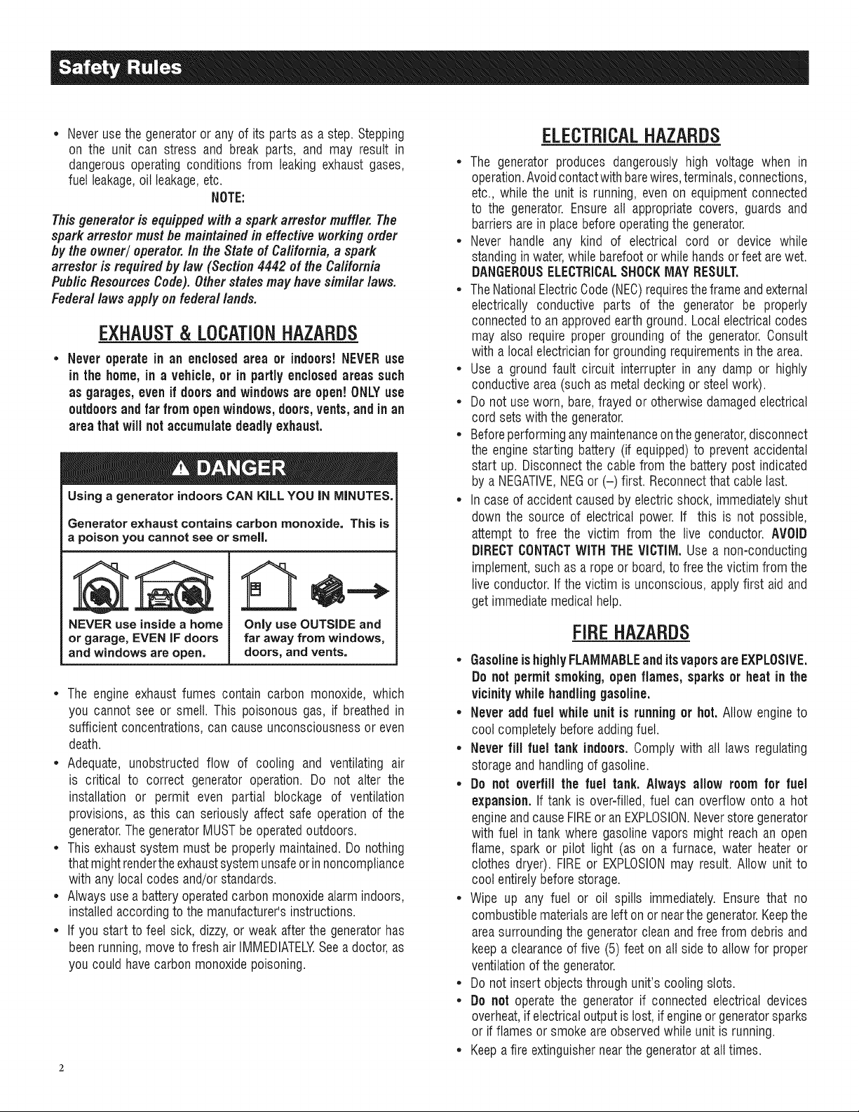
EXHAUST & LOCATIONHAZARDS
• Never operate in an enclosed area or indoors!NEVERuse
in the home,in a vehicle,or in partlyenclosedareas such
as garages, even if doors and windowsare open! ONLYuse
outdoors and far from openwindows,doors,vents,andinan
areathat will notaccumulatedeadly exhaust.
Using a generator indoors CAN KiLL YOU JN MINUTES.
Generator exhaust contains carbon monoxide. This is
a poison you cannot see or smell.
NEVER use insidea home
or garage, EVEN JFdoors
and windows are open.
* The engine exhaustfumes contain carbon monoxide, which
you cannot see or smell. This poisonous gas, if breathedin
sufficientconcentrations,can causeunconsciousnessor even
death.
* Adequate, unobstructed flow of cooling and ventilating air
is critical to correct generator operation. Do not alter the
installation or permit even partial blockage of ventilation
provisions, as this can seriously affect safe operationof the
generator.ThegeneratorMUSTbeoperatedoutdoors.
* This exhaustsystemmust be properly maintained.Do nothing
that mightrendertheexhaustsystemunsafeorinnoncompliance
with any localcodes and/orstandards.
* Always usea batteryoperatedcarbonmonoxidealarmindoors,
installedaccordingto themanufacturer'sinstructions.
* If you start to feet sick, dizzy,or weak after the generatorhas
beenrunning,moveto fresh air IMMEDIATELYSeea doctor,as
you couldhave carbonmonoxidepoisoning.
Only use OUTSIDE and
far away from windows,
doors, and vents.
ELECTRICALHAZARDS
* The generator produces dangerously high voltage when in
operation.Avoidcontactwith barewires,terminals,connections,
etc., while the unit is running,even on equipmentconnected
to the generator. Ensureall appropriate covers, guards and
barriersarein placebeforeoperatingthe generator.
* Never handle any kind of electrical cord or device while
standinginwater,while barefootorwhile handsor feet arewet.
DANGEROUSELECTRICALSHOCKMAYRESULT.
* TheNationalElectricCode(NEC)requirestheframe andexternal
electrically conductive parts of the generator be properly
connectedto an approvedearth ground.Local electricalcodes
may also require proper grounding of the generator.Consult
with a localelectricianfor groundingrequirementsin thearea.
* Use a ground fault circuit interrupter in any damp or highly
conductivearea(such as metaldecking or steelwork).
* Do not useworn, bare,frayed or otherwise damagedelectrical
cord setswith the generator.
* Beforeperforminganymaintenanceonthegenerator,disconnect
the enginestarting battery (if equipped)to preventaccidental
start up. Disconnectthe cablefrom the batterypost indicated
by a NEGATIVE,NEGor (-) first. Reconnectthatcable last.
* In caseof accident causedby electricshock, immediatelyshut
down the source of electrical power.If this is not possible,
attempt to free the victim from the live conductor. AVOID
DIRECTCONTACTWITH THEVICTIM, Use a non-conducting
implement,such asa rope or board,to freethevictim fromthe
live conductor.If the victim is unconscious, applyfirst aidand
getimmediatemedical help.
FiREHAZARDS
• GasolineishighlyFLAMMABLEand itsvaporsare EXPLOSIVE.
Do not permitsmoking,open flames, sparksor heat in the
vicinitywhilehandlinggasoline.
• Never add fuel while unit is runningor hot.Allow engineto
cool completelybeforeaddingfuel.
• Never fill fuel tankindoors, Comply with all laws regulating
storageand handlingof gasoline.
• Do not overfill the fuel tank. Always allow roomfor fuel
expansion. If tank is over=filled,fuel can overflow onto a hot
engineandcauseFIREor an EXPLOSION.Neverstoregenerator
with fuel in tankwhere gasolinevapors might reach an open
flame, spark or pilot light (as on a furnace, water heateror
clothes dryer). FIREor EXPLOSIONmay result. Allow unit to
cool entirelybeforestorage.
• Wipe up any fuel or oil spills immediately. Ensure that no
combustiblematerialsareleft on or nearthe generator.Keepthe
areasurroundingthe generatorcleanandfree from debrisand
keepa clearanceof five (5) feet on all side to allow for proper
ventilationof the generator.
• Do not insert objectsthrough unit's cooling slots.
• Do not operatethe generator if connected electrical devices
overheat,if electricaloutputislost,if engineor generatorsparks
or if flames or smoke are observedwhile unit is running.
• Keepafire extinguishernearthe generatoratall times.
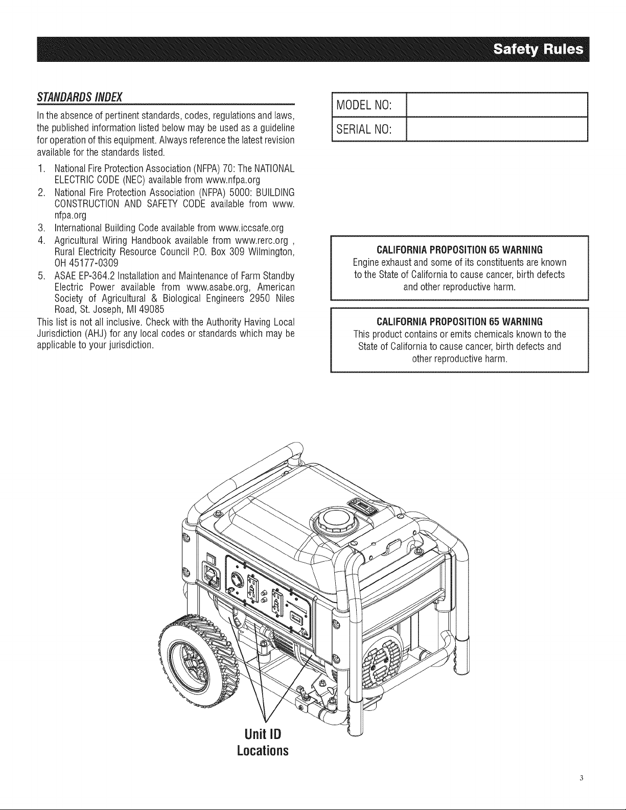
STANDARDS/#DEX
Inthe absenceof pertinentstandards,codes,regulationsandtaws,
the publishedinformation listedbelowmay be usedas a guideline
foroperationofthis equipment.Alwaysreferencethelatestrevision
availablefor the standardslisted.
1. NationalFireProtectionAssociation(NFPA)70:TheNATIONAL
ELECTRICCODE(NEC)availablefrom www.nfpa.org
2. NationalFire ProtectionAssociation(NFPA)5000: BUILDING
CONSTRUCTIONAND SAFETYCODEavailablefrom www.
nfpa.org
3. InternationalBuildingCodeavailablefrom www.iccsafe.org
4. Agricultural Wiring Handbookavailablefrom www.rerc.org ,
Rural ElectricityResourceCouncil P.O.Box 309 Wilmington,
OH45177-0309
5. ASAEEP-364.2InstallationandMaintenanceof FarmStandby
Electric Power available from www.asabe.org, American
Society of Agricultural & Biological Engineers2950 Niles
Road,St. Joseph,MI 49085
This list is not all inclusive.Checkwith theAuthority HavingLocal
Jurisdiction (AHJ)for any localcodes or standardswhich maybe
applicableto your jurisdiction.
MODELNO:
SERIALNO:
CALIFORNIAPROPOSITION55 WARNING
Engineexhaustandsomeof its constituentsareknown
to theStateof Californiato causecancer,birth defects
and otherreproductiveharm.
CALIFORNIAPROPOSITION55 WARNING
This productcontainsor emitschemicalsknown tothe
Stateof Californiato causecancer,birth defects and
otherreproductiveharm.
UnitID
Locations
1.1 UNPACKING
• Removeall packagingmaterial.
• Removeseparateaccessorybox.
• Removecarton off the generator.
1.1.1 ACCESSORYBOX
Checkall contents(Figure1). If anyparts aremissingor damaged
locatean authorizeddealerat1-888-436-3722.
Contentsinclude:
• 2-Axle Pins • OilFilter
• 2- WheelSpacers • Air Filter
• 2- HairPins • SparkPlug
• 2- Wheels • SparkPlugWrench
• 1- FrameFoot • ShopTowel
• 1- FrameBolt • 1 QuartSAE30Oil Bottle
• 1- FrameFlatWasher • OilFunnel
• 3- FlangeNuts • 2 - VibrationMounts
Figure 1 - Accessory Box
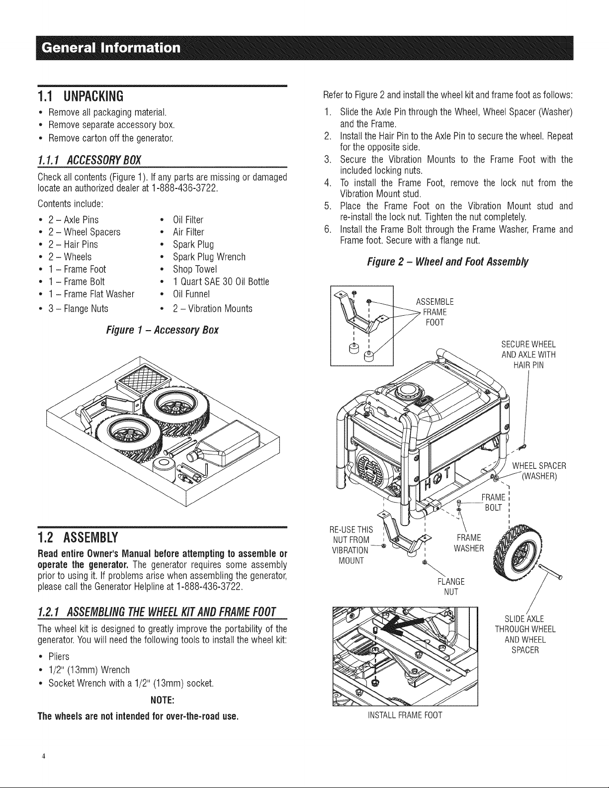
Referto Figure2andinstallthe wheelkit andframefoot asfollows:
1. Slidethe AxlePinthroughthe Wheel,WheelSpacer(Washer)
andthe Frame.
2. Installthe Hair Pintothe AxlePinto securethewheel. Repeat
for the oppositeside.
3. Secure the Vibration Mounts to the Frame Foot with the
includedlocking nuts.
4. To install the Frame Foot, remove the lock nut from the
VibrationMount stud.
5. Place the Frame Foot on the Vibration Mount stud and
re-installthelock nut.Tightenthe nutcompletely.
6. Installthe FrameBolt through the FrameWasher,Frameand
Framefoot. Securewith a flangenut.
Figure 2 - Wheel and Foot Assembly
ASSEMBLE
FRAME
FOOT
SECUREWHEEL
ANDAXLEWITH
HAIRPIN
1.2 ASSEMBLY
Readentire Owner's Manual beforeattemptingto assemble or
operatethe generator. The generatorrequires some assembly
priorto usingit. If problems arise whenassemblingthegenerator,
pleasecall the GeneratorHelplineat 1-888-436-3722.
1.2.1 ASSEMBLINGTHEWHEELKITANBFRAMEFOOT
Thewheel kit is designedto greatly improvethe portability of the
generator.Youwilt needthe following tools to installthewheel kit:
• Pliers
• 1/2" (13mm)Wrench
• SocketWrenchwith a1/2" (13mm)socket.
NOTE:
The wheelsare notintendedfor over-the-roaduse.
RE-USETHIS
NUTFROM
VIBRATION--_
MOUNT
t
WHEELSPACER
FRAME
BOLT
FRAME
WASHER
FLANGE
NUT
SLIDEAXLE
THROUGHWHEEL
ANDWHEEL
SPACER
INSTALLFRAMEFOOT

2.1 KNOWTHEGENERATOR
Read the Owner'sIVlanualand Safety Rules before operating
thisgenerator.
Comparethegeneratorto Figure3to becomefamiliarizedwith the
locations of various controls and adjustments.Savethis manual
for future reference.
1. Run/StopSwitch - Controlsthe operationof the generator.
2. FuelShut Off - Valvebetweenfueltank andcarburetor.Turn
off and run carburetoroutof fuelfor extendedstorage.
3. Panel LED's- Provideilluminationof the control panelwhile
thegeneratoris operating.
4. 120/240 Volt AC, 20 Amp LockingReceptacle- Supplies
electricalpower for the operationof 120 and/or 240 VoltAC,
20 Amp, single-phase,60 Hz, electrical lighting, appliance,
tool andmotor loads.
5. 120 Volt AC,20 Amp, GFCiDuplexReceptacle - Supplies
electrical power for the operationof 120 Volt AC, 20 Amp,
single-phase, 60 Hz electrical lighting, appliance,tool and
motor loads. It also provides protection with an Integral
Ground Fault Circuit Interrupter, complete with a press to
"Test"and "Reset"button.
6. CircuitBreakers(AC) - The push-to-reset circuit breakers
(49 state model) or the 2-pole circuit breaker (CSA/CARB
models) are rated at 20 Amps; this protects the generator
againstelectricaloverload.
7. Hourmeter- Providesoperatinghours for Service Intervals.
8. PowerBar- Indicatesthe amountof power being used from
thegenerator;each section is approximately20%.
g. FuelTank- Tankholds4.5 U.S.gallonsof fuel.
10. FuelGauge- Showsfuel levelin tank.
11. Handles - Pivot and retractfor storage. Press the spring-
loadedbuttonto move handles.
12. Oil Fill- Checkoil level andadd oil here.
13. Grounding Lug- Groundthe generatorto an approvedearth
groundhere.See"GroundingtheGenerator"for details.
14. Muffler - Includesthe sparkarrestor andquietsthe engine.
15. Spark Plug- Ignites Air/Fuel Mixture (Side panel must be
removed).
15. EngineOil Filter- Filtersengineoil; seeSection 3.1 for the
properservice intervals.
17. Choke- Usedwhenstarting a cold engine.
18, AirCleaner- Filtersintakeair as it is drawn intothe engine.
19. Oil Drain- Drain valveto remove used oil from the engine
crankcase.
20. RecoilStarter - Useto start enginemanually.
"21. CarbonCanister- Absorbs fuel tank vapors.
22. Roll OverValve - Passesfuel vaporsto the carboncanister.
23. Recovery Hose- Installedbetweenthe engineair intake,the
carboncanister andthe RollOverValve.
* Californiamodelonly,
Figure 3 - Generator Locations and Controls
49 State
1 4 5 8
@ @
2 3 6 7 3
CSA/CARB
1 4 5 8
2 3 6 7 3
12
13
23
21
22
11
15
16 20
18
17
2.2 HOURMETER=NORESET
The Hourmeter tracks hours of operation
maintenance:
Therewill be a onetime breakin "CHGOIL"messagethat flashes
with the elapsedtime in hours and tenths after thefirst 30 hours
of operation.
This messagewill actuallybeginflashing at 29 hoursand disable
itself at 31 hours providing a two hour window to perform the
service.
Therewill be a subsequent"CHGOIL"messageevery 100 hours.
Themessage wilt flash one hour before and onehour after each
100 hour interval,again providinga two hour window to perform
service.
Every200 hours the "SVC"icon on the lower left hand corner of
the display will flash. Themessagewill flash one hourbefore and
onehourafter each200 hourintervalprovidingatwo hourwindow
to perform service.
Whenthe hour meter is inthe FlashAlert mode, the maintenance
message will always alternate with elapsedtime in hours and
tenths. The hours wilt flash four times, then alternate with the
maintenancemessagefour times untilthe meter resets itself.
,, 100 hours - CHGOIL-- Oil ChangeInterval(Every100 hrs)
* 200 hours- SVC-- Air FilterInterval(Every200 hrs)
for scheduled
Fora newgeneratorfor instance,the messagewill say "CHGOIL"
thenflash "in30". This meansthat in 30 hours, the oil wilt needto
be changed. Pressingthe button a few more times will bring the
meter backto the screenthat shows the total hoursrun.
Reset: Toggleto the alert that you wish to reset then hold the
buttondownfor 9 seconds.Themaintenancehoursareresetwhen
thedisplay shows "0000.0".
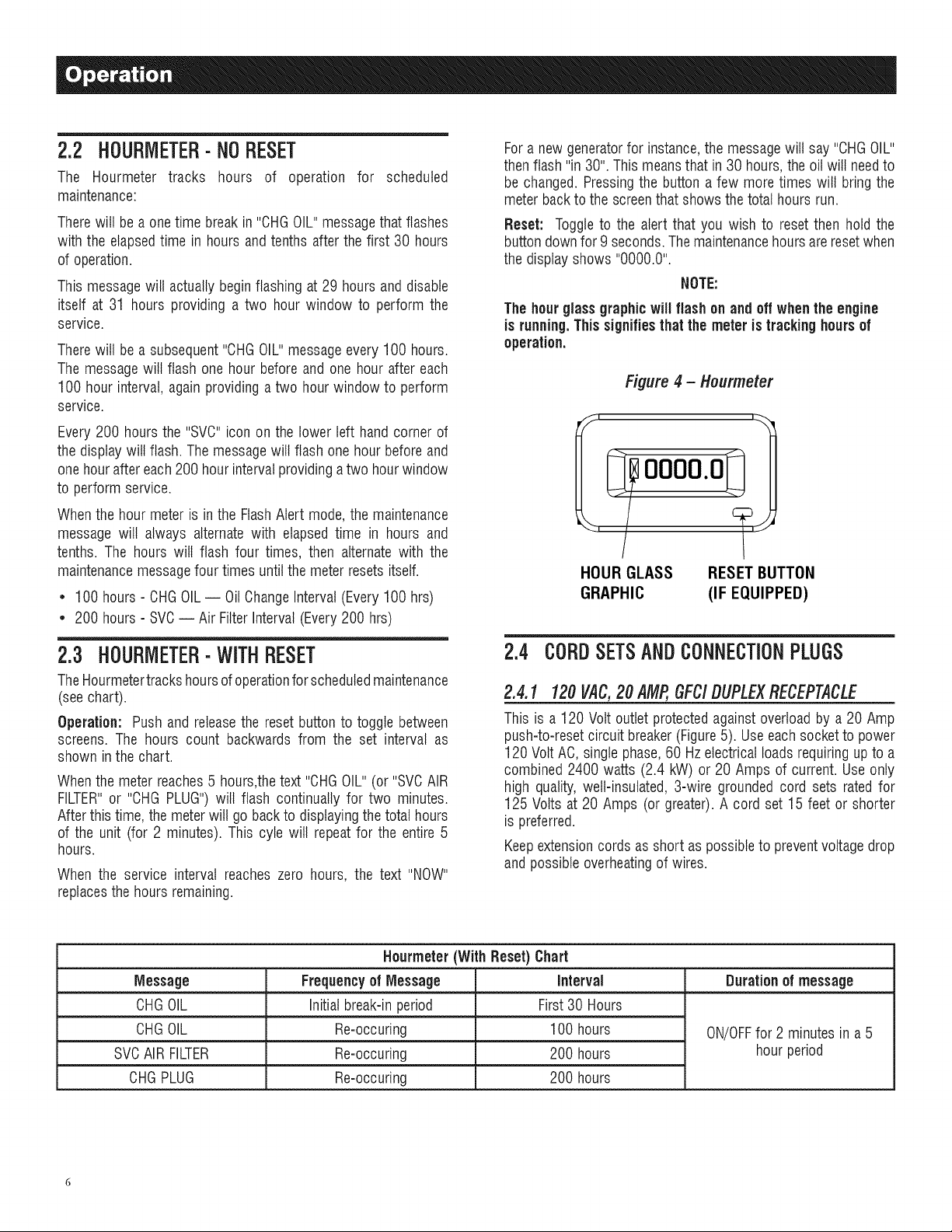
NOTE:
Thehourglass graphic willflashon and off whenthe engine
is running.Thissignifiesthatthe meter is trackinghours of
operation.
Figure 4 - Hourmeter
OOOO'O
HOUR GLASS RESETBUTTON
GRAPHIC (IF EQUIPPED)
2.3 HOURMETEB=WITHRESET
TheHourmetertrackshoursof operationforscheduledmaintenance
(seechart).
Operation: Pushand releasethe reset button to toggle between
screens. The hours count backwards from the set interval as
shown in the chart.
Whenthe meter reaches5 hours,thetext"CHGOIL"(or"SVCAIR
FILTER"or "CHG PLUG")will flash continually for two minutes.
Afterthis time, the meterwill go backto displayingthe total hours
of the unit (for 2 minutes). This cyle will repeatfor the entire 5
hours.
When the service interval reacheszero hours, the text "NOW"
replacesthe hours remaining.
Nourmeter(With Reset) Chart
Message Frequencyof Message Interval Duration of message
CHGOIL Initialbreak-inperiod First30 Hours
CHGOIL Re-occuring 100 hours ON/OFFfor 2 minutes in a 5
SVCAIR FILTER Re-occuring 200 hours hour period
CHGPLUG Re-occuring 200 hours
2.4 CORDSETSANDCONNECTIONPLUGS
2.4.1 120VAC,20AMP,GFC/DUPLEXRECEPTACLE
This is a 120 Volt outlet protectedagainst overloadby a 20 Amp
push-to-resetcircuitbreaker (Figure5). Useeach socketto power
120 VoltAC, singlephase,60 Hzelectrical loadsrequiringupto a
combined 2400 watts (2.4 kW) or 20 Amps of current.Use only
high quality, welt-insulated,3-wire groundedcord sets ratedfor
125 Volts at 20 Amps (or greater).A cord set15 feet or shorter
is preferred.
Keepextensioncords as short as possibleto preventvoltagedrop
and possibleoverheatingof wires.
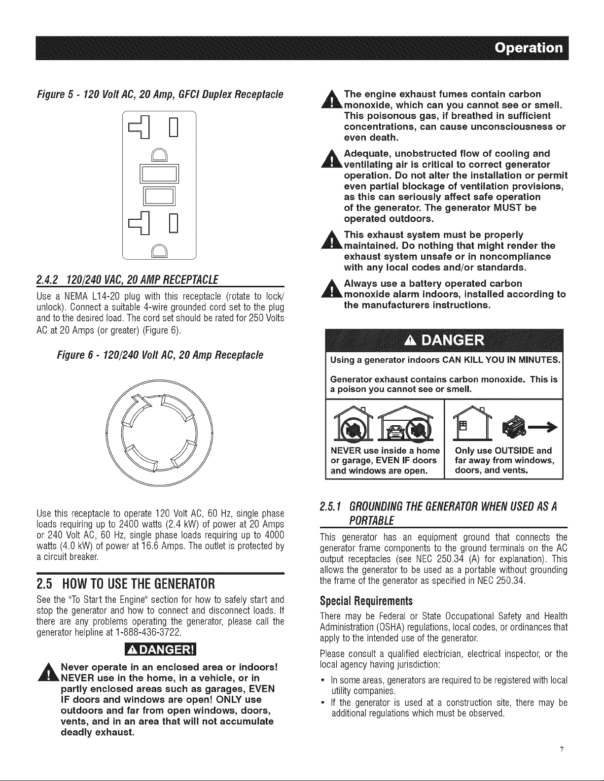
Figure 5 - 120 Vo/t AC, 20 Amp, GFC/ Duplex Receptac/e
2.4.2 120/240 VAC,20 AMPRECEPTACLE
Use a NEMA L14-20 plug with this receptacle (rotate to lock!
unlock). Connecta suitable4-wire groundedcord set to the plug
andto thedesiredtoad.Thecordset should be ratedfor 250 Volts
ACat 20 Amps (or greater)(Figure6).
_t he engine exhaust fumes contain carbon
monoxide, which can you cannot see or smell.
This poisonous gas, if breathed in sufficient
concentrations, can cause unconsciousness or
even death.
_t Adequate, unobstructed flow of cooling and
ventilating air is critical to correct generator
operation. Do not alter the installation or permit
even partial blockage of ventilation provisions,
as this can seriously affect safe operation
of the generator. The generator MUST be
operated outdoors.
_t This exhaust system must be properly
maintained. Do nothing that might render the
exhaust system unsafe or in noncompliance
with any local codes and/or standards.
AIways use a battery operated carbon
monoxide alarm indoors, installed according to
the manufacturers instructions.
Figure 6 - 120/240 VoRAC, 20 Amp Receptac/e
Use this receptacleto operate120 Volt AC, 60 Hz, singlephase
loads requiringup to 2400 watts (2.4 kW) of power at 20 Amps
or 240 Volt AC, 60 Hz,single phase loads requiring up to 4000
watts (4.0 kW) of powerat 16.6 Amps. The outletis protectedby
a circuit breaker.
2,5 HOWTOUSETHEGENERATOR
Seethe "ToStart the Engine"sectionfor howto safelystart and
stop the generator and how to connect and disconnect loads. If
there are any problems operatingthe generator,pleasecall the
generatorhelplineat 1-888-436-3722.
Never operate in an encJosed area or indoors!
NEVER use in the home, in a vehicJe, or in
partly encJosed areas such as garages, EVEN
iF doors and windows are open! ONLY use
outdoors and far from open windows, doors,
vents, and in an area that will not accumulate
deadly exhaust.
Using a generator indoors CAN KiLL YOU iN MINUTES.
Generator exhaust contains carbon monoxide. This is
a poison you cannot see or smell.
NEVER use inside a home
or garage, EVEN iF doors
and windows are open.
Only use OUTSIDE and
far away from windows,
doors, and vents.
2.5.1 GROUNDINGTHEGENERATORWHENUSEDASA
PORTABLE
This generator has an equipment ground that connects the
generatorframe componentsto the groundterminals on the AC
output receptacles (see NEC 250.34 (A) for explanation).This
allows the generatorto be used as a portable without grounding
theframe ofthe generatoras specifiedin NEC250.34.
SpecialRequirements
There may be Federalor State Occupational Safety and Health
Administration(OSHA)regulations,localcodes, or ordinancesthat
applyto the intendeduse ofthe generator.
Pleaseconsult a qualified electrician, electrical inspector, or the
local agencyhavingjurisdiction:
* In someareas,generatorsarerequiredtoberegisteredwith local
utilitycompanies.
* If the generatoris used at a construction site, there may be
additionalregulationswhich mustbe observed.
2.5.2 CONNECTINGTHEGENERATORTOA BU/LD/NG'S
ELECTRICALSYSTEM
Connectionsfor standby power to a building's electrical system
must be made by a qualifiedelectricianand in strict compliance
with all national and local electrical codes and laws. The
connectionmust isolatethe generatorpowerfrom utility power or
otheralternativepowersources.
NOTE:
Becausethe generatorequipment groundis bondedto the AC
neutral wires in thegenerator(see Figure8), either a 3-pole
transferswitchor a 2 pole transferswitchwith a switching
neutralkit is requiredto connectthisgenerator to a building
load. Inthis application the generator becomes a separately
derived system(seeNEC250.20 (D)), and mustbegrounded
in accordancewith thenationalorlocalelectrical code
requirements.
GroundingtheGeneratorina BuildingStandbyApplication
The National Electrical Code requires that the frame and
external electrically conductiveparts of this generator be
properlyconnectedto an approvedearth ground (Figure 7).
Local electrical codes also require grounding of the unit. For
that purpose,connecting a No.10 AWG (AmericanWire Gauge)
strandedcopperwire to the groundinglug and to an earth-driven
copper or brass grounding rod (electrode) provides adequate
protection against electrical shock. However, local codes may
vary widely. Consultwith a local electrician for grounding
requirementsin the area.
Proper grounding of the generator will help preventelectrical
shockin the event of a ground fault condition in the generator
or in connectedelectrical devices. Proper grounding also helps
dissipate static electricity, which often builds up in ungrounded
devices.
Figure7 - Groundingthe Generator
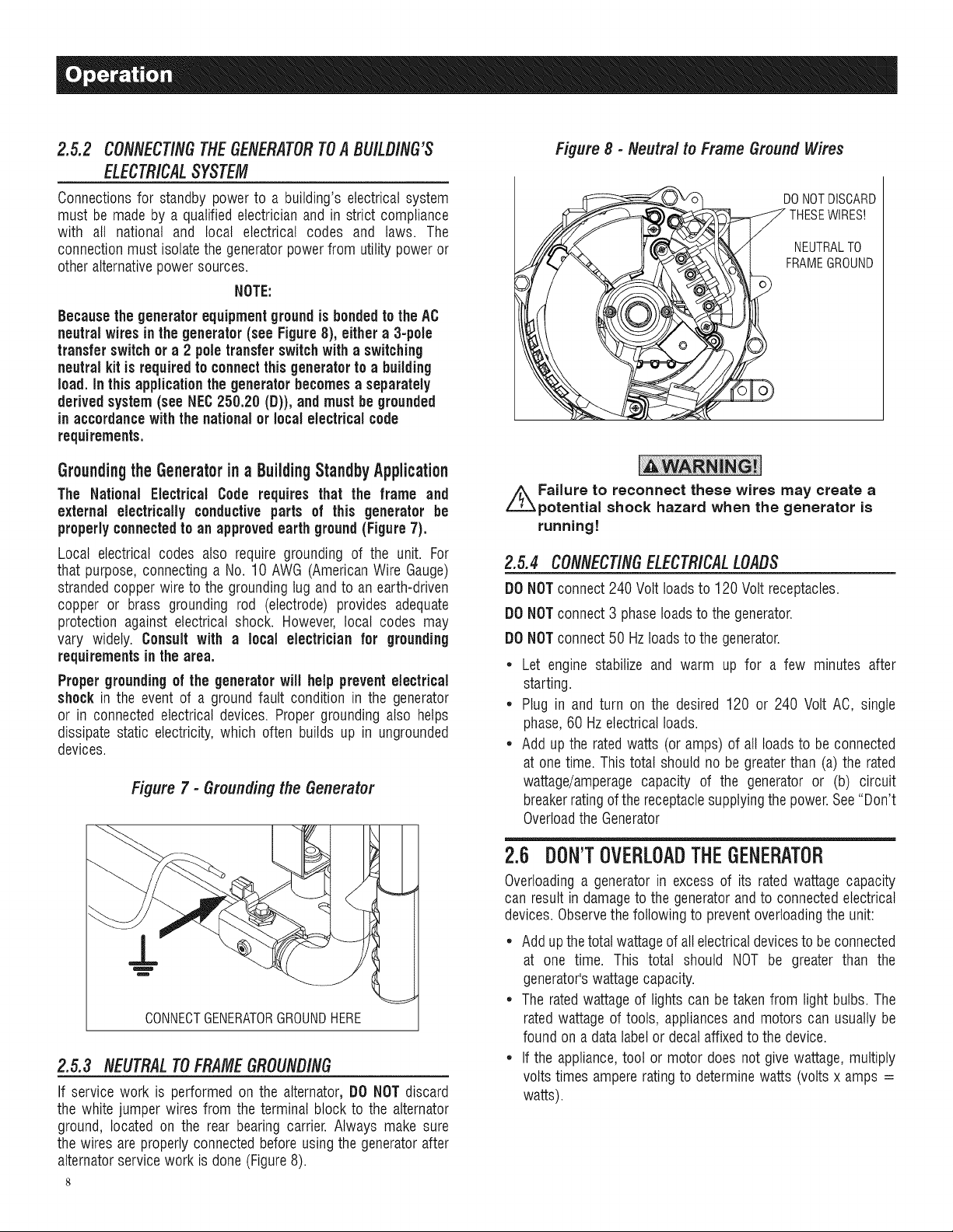
Figure8 - Neutral to FrameGroundWires
DONOTDISCARD
THESEWIRES!
NEUTRALTO
FRAMEGROUND
//_Failure to reconnect these wires may create a
potential shock hazard when the generator is
running!
2.5.4 CONNECtiNGELECTR/CALLOADS
DONOTconnect 240 Volt loadsto 120 Voltreceptacles.
DONOTconnect 3 phaseloadsto the generator.
DONOTconnect 50 Hzloadsto the generator.
* Let engine stabilize and warm up for a few minutes after
starting.
* Plug in and turn on the desired 120 or 240 Volt AC, single
phase,60 Hzelectrical loads.
* Add up the ratedwatts (or amps)of all loadsto be connected
at one time. This total should no be greaterthan (a)the rated
wattage/amperagecapacity of the generator or (b) circuit
breakerratingofthe receptaclesupplyingthepower.See"Don't
OverloadtheGenerator
CONNECTGENERATORGROUNDHERE
2.5.3 NEUTRALTOFRAMEGROUNDING
If service work is performed on the alternator,DO NOTdiscard
the white jumper wires from the terminal blockto the alternator
ground, located on the rear bearing carrier. Always make sure
the wires are properlyconnected beforeusingthe generatorafter
alternatorservicework is done (Figure8).
2.6 DON'TOVERLOADTHEGENERATOR
Overloadinga generatorin excess of its ratedwattage capacity
can result in damageto the generatorandto connectedelectrical
devices.Observethefollowing to preventoverloadingthe unit:
* Addupthetotal wattageofallelectricaldevicesto be connected
at one time. This total should NOT be greater than the
generator'swattagecapacity.
* The ratedwattageof lights can betaken from light bulbs. The
ratedwattage of tools, appliancesand motors can usually be
foundon a data labelor decal affixedto the device.
* If the appliance,tool or motor does not give wattage,multiply
voltstimes ampereratingto determinewatts (voltsx amps =
watts).
• Some electric motors, such as inductiontypes, requireabout
threetimes more watts of powerfor starting than for running.
This surge of power lasts only a few seconds when starting
such motors. Makesureto allowfor highstarting wattagewhen
selectingelectricaldevicesto connectto the generator:
1. Figurethewatts neededto start thelargest motor.
2. Add to that figure the running watts of all other connected
loads.
TheWattageReferenceGuideis providedto assist in determining
howmany itemsthe generatorcan operateat onetime.
*Refrigerator .............................................. 700
Slow Cooker............................................... 200
*Submersible Pump (1-1/2 HP)............................... 2800
*Submersible Pump (1 HP) .................................. 2000
*Submersible Pump (1/2 HP)................................. 1500
*Sump Pump....................................... 800to 1050
*Table Saw (10") ................................... 1750 to 2000
Television........................................... 200 to 500
Toaster........................................... 1000 to 1650
WeedTrimmer ............................................. 500
* Allow 3 times the listed watts for starting these devices.
2.7 WATTAGEREFERENCEGUIDE
NOTE:
Allfigures are approximate. Seedata labelon appliancefor
wattage requirements.
Device.......................................... RunningWatts
*Air Conditioner(12,000 Btu)................................. 1700
*Air Conditioner(24,000 Btu)................................. 3800
*Air Conditioner(40,000 Btu)................................. 6000
Battery Charger(20 Amp) .................................... 500
Belt Sander (3") ........................................... 1000
Chain Saw............................................... 1200
Circular Saw (6-1/2") ................................. 800 to 1000
*Clothes Dryer (Electric) .................................... 5750
*Clothes Dryer (Gas) ........................................ 700
*Clothes Washer .......................................... 1150
CoffeeMaker ............................................. 1750
*Compressor (1HP) ....................................... 2000
*Compressor (3/4 HP)...................................... 1800
*Compressor (1/2 HP)...................................... 1400
OurlingIron ............................................... 700
*Dehumidifier.............................................. 650
Disc Sander (9")........................................... 1200
EdgeTrimmer.............................................. 500
Electric Blanket............................................. 400
Electric NailGun........................................... 1200
Electric Range(per element).................................. 1500
Electric Skillet............................................. 1250
*Freezer.................................................. 700
*Furnace Fan(3/5 HP)....................................... 875
*Garage Door Opener.................................. 500 to 750
Hair Dryer ............................................... 1200
HandDrill .......................................... 250to 1100
HedgeTrimmer............................................. 450
Impact Wrench............................................. 500
Iron .................................................... 1200
*Jet Pump ................................................ 800
Lawn Mower ............................................. 1200
Light Bulb................................................. 100
Microwave Oven..................................... 700 to 1000
*Milk Cooler.............................................. 1100
OilBurner on Furnace........................................ 300
OilFired Space Heater(140,000 Btu)............................ 400
OilFired Space Heater(85,000 Btu)............................. 225
OilFired Space Heater(30,000 Btu)............................. 150
*Paint Sprayer,Airless (1/3 HP)................................ 600
PaintSprayer,Airless (handheld) ............................... 150
Radio ............................................... 50 to 200
2.8 BEFORESTARTINGTHEGENERATOR
Prior to operatingthe generator,engineoil and gasolinewill need
to beadded,as follows:
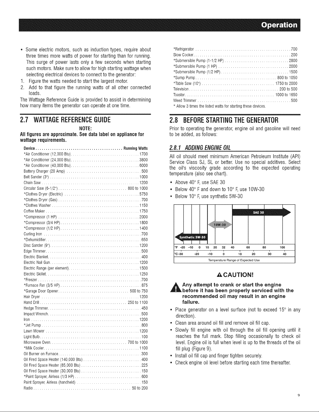
2.8.1 ADD/NGENG/NEO/L
All oil should meet minimum American PetroleumInstitute (API)
Service Class SJ, SL or better.Useno special additives. Select
the oil's viscosity grade according to the expected operating
temperature(also seechart).
• Above40° F,useSAE30
• Below40° Fand downto 10° F,use10W-30
• Below 10° F,usesynthetic5W-30
mEm
7I
°F -20 -!0 O 10 20 32 40 60 80 leo
oc-3'o -_o -;o ; 1'0 2'0 3'o 4?
Temperature Range of Expected Use
,&,CAUTION!
_t ny attempt to crank or start the engine
before it has been properly serviced with the
recommended oil may result in an engine
failure.
• Place generatoron a level surface (not to exceed15° in any
direction).
• Cleanareaaroundoil fill and removeoil fill cap.
• Slowly fill engine with oil through the oil fill opening until it
reaches the full mark. Stop filling occasionally to check oil
level. Engineoil isfull when levelis up to thethreadsof the oil
fill plug (Figure9).
• Installoil fill cap andfinger tightensecurely.
• Checkengineoil levelbeforestarting eachtime thereafter.
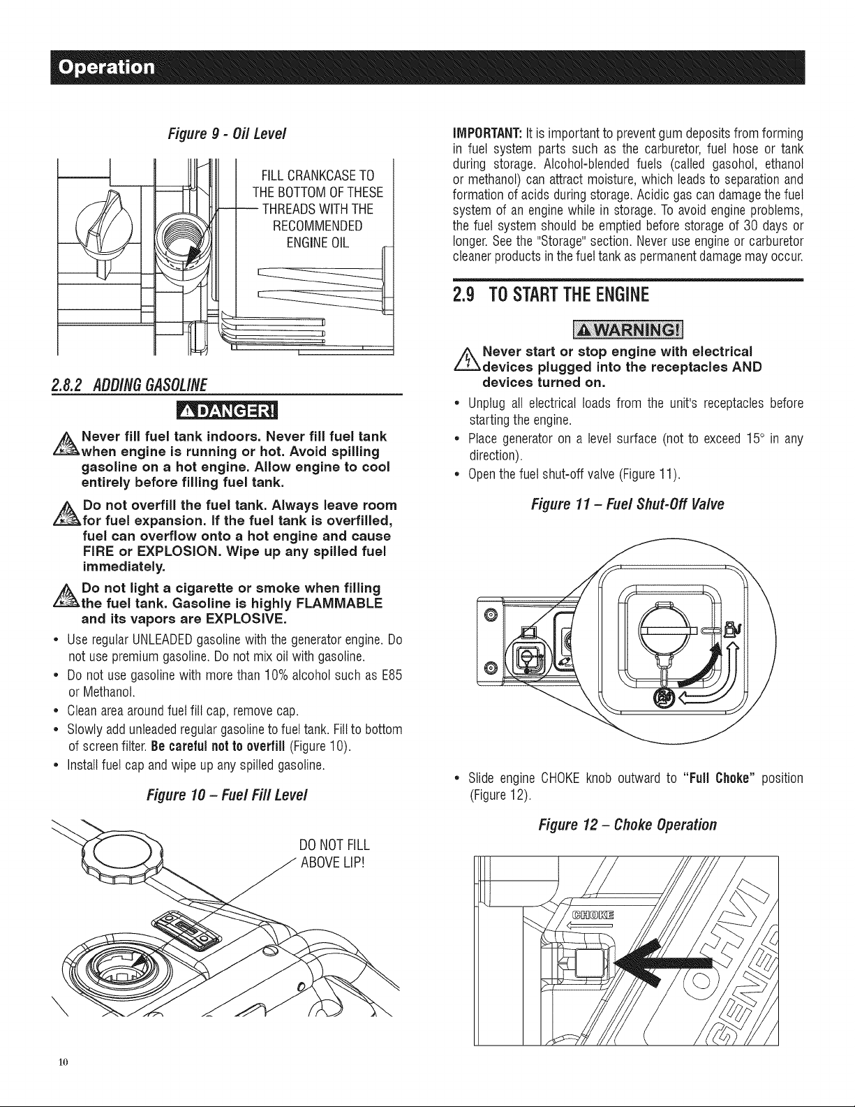
Figure g - Oil Level
m
THEBOTTOMOFTHESE
- -- THREADSWITHTHE
FILLCRANKCASETO
RECOMMENDED
ENGINEOIL
IMPORTANT:Itis important to preventgum depositsfromforming
in fuel system parts such as the carburetor,fuel hose or tank
during storage. Alcohol-blendedfuels (called gasohol, ethanol
or methanol)can attract moisture, which leadsto separationand
formationof acids duringstorage.Acidic gascandamagethefuel
system of an enginewhile in storage.Toavoid engineproblems,
the fuel system should be emptiedbefore storage of 30 days or
longer.Seethe "Storage"section. Neveruseengineor carburetor
cleanerproducts inthefueltank aspermanentdamagemay occur.
m
m
V ,
2.8,2 ADD/fiGGASOLINE
Never fill fuel tank indoors. Never fill fuel tank
when engine is running or hot. Avoid spilling
gasoline on a hot engine. Allow engine to cool
entirely before filling fuel tank.
z_Do not overfill the fuel tank. Always leave room
for fuel expansion. If the fuel tank is overfilled,
fuel can overflow onto a hot engine and cause
FiRE or EXPLOSION. Wipe up any spilled fuel
immediately.
Do not light a cigarette or smoke when filling
the fuel tank. Gasoline is highly FLAMMABLE
and its vapors are EXPLOSIVE.
• UseregularUNLEADEDgasofinewith the generatorengine.Do
not usepremiumgasoline.Do not mix oilwith gasoline.
• Do not use gasolinewith more than 10% alcohol such as E85
or Methanol.
• Cleanareaaroundfuel fill cap, removecap.
• Slowlyaddunleadedregulargasolineto fueltank. Fillto bottom
of screenfilter.Be carefulnotto overfill (Figure10).
• Installfuel cap andwipe up any spilled gasoline.
Figure 10 - Fuel Fill Level
2.9 TOSTARTTHEENGINE
//_Never start or stop engine with electrical
devices plugged into the receptacles AND
devices turned on.
• Unplug all electrical loads from the unit's receptaclesbefore
startingthe engine.
• Place generatoron a levelsurface (not to exceed15° in any
direction).
• Openthefuel shut-off valve (Figure11).
Figure 11 - Fuel Shut-Off Valve
Slide engine CHOKEknob outward to "FullChoke"position
(Figure12).
Figure 12- Choke Operation
DONOTFILL
ABOVELIP!
\
1o
NOTE:
The engine switchmustbe in the ONposition.
* Tostart manually,firmly grasp therecoil handleand pull slowly
until increasedresistance is felt. Pull rapidly up and away to
start engine. Then follow the same choke sequence listed
above.
* When the engine starts, slide choke knob to "1/2 Choke"
position untilthe engine runssmoothly andthenfully in to the
"Run" position. If enginefalters, slide chokeknob backout to
"1/2 Choke"position until the engine runs smoothly and then
to "Run" position.
NOTE:
If engine fires,but doesnot continuetorun,pull chokeknobto
"Full Choke"and repeatstartinginstructions.
A, CAUTION!
,_Do not overload the generator. Also, do
not overload individual panel receptacles.
These outlets are protected against overload
with push=to=reset=type circuit breakers, if
amperage rating of any circuit breaker is
exceeded, that breaker opens and electrical
output to that receptacle is lost. Read "Don't
Overload the Generator" carefully.
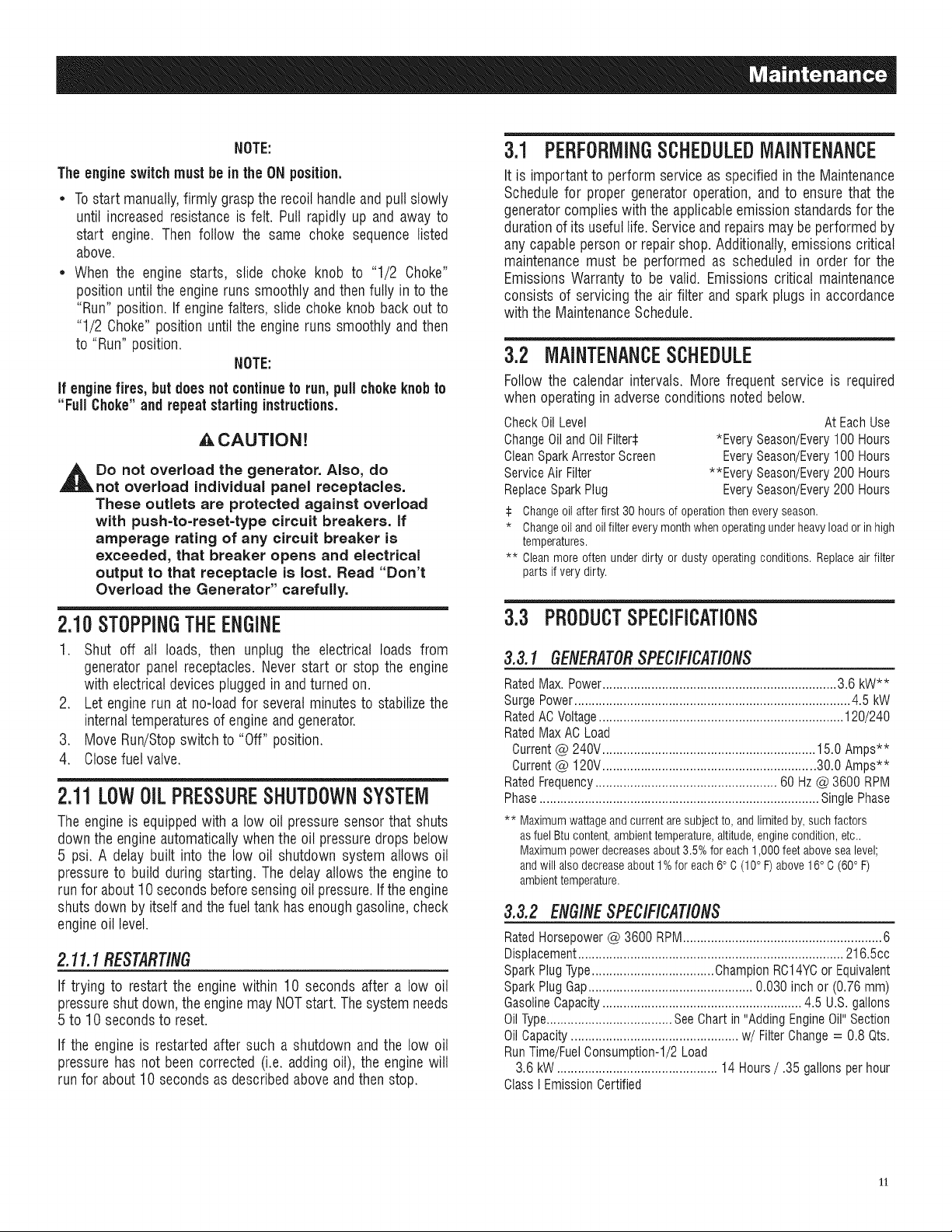
3.1 PEBFOBIVlINGSCHEDULEDMAINTENANCE
It is importantto performserviceas specified in the Maintenance
Schedulefor proper generatoroperation, and to ensure that the
generatorcomplieswith the applicableemissionstandardsfor the
durationof its usefullife. Serviceand repairsmaybe performedby
anycapable personor repairshop. Additionally,emissionscritical
maintenancemust be performed as scheduled in order for the
Emissions Warrantyto be valid. Emissions critical maintenance
consists of servicingthe air filter and spark plugs in accordance
with the MaintenanceSchedule.
3.2 MAINTENANCESCHEDULE
Follow the calendar intervals. More frequent service is required
whenoperatingin adverseconditions notedbelow.
CheckOilLevel AtEachUse
ChangeOilandOilFilters *EverySeason/Every100Hours
CleanSparkArrestorScreen EverySeason/Every100Hours
ServiceAirFilter **EverySeason/Every200Hours
ReplaceSparkPlug EverySeason/Every200Hours
:i: Changeoil after first 30 hours of operationthen every season.
* Changeoil and oilfilter every monthwhen operatingunderheavyload or in high
temperatures.
** Clean more often under dirty or dusty operating conditions. Replace air filter
parts if verydirty.
2.10STOPPINGTHEENGINE
1. Shut off all loads, then unplug the electrical loads from
generatorpanel receptacles.Never start or stop the engine
with electricaldevicespluggedin andturnedon.
2. Let enginerun at no-load for severalminutesto stabilizethe
internaltemperaturesof engineand generator.
3. Move Run/Stopswitch to "Off" position.
4. Closefuelvalve.
2.11LOW01LPRESSURESHUTDOWNSYSTEM
Theengineis equippedwith a low oil pressuresensorthat shuts
downthe engineautomaticallywhenthe oil pressuredropsbelow
5 psi. A delay built into the low oil shutdown system allows oil
pressureto build during starting. The delay allows the engineto
run for about10 secondsbeforesensingoil pressure.If theengine
shutsdown by itself andthe fueltank hasenoughgasoline,check
engineoil level.
2.1I.IRESTARTING
If trying to restart the engine within 10 seconds after a low oil
pressureshut down, theenginemay NOTstart. Thesystemneeds
5 to 10 secondsto reset.
If the engine is restarted after such a shutdown and the low oil
pressure has not been corrected (i.e. adding oil), the enginewill
run for about10secondsas describedabove andthen stop.
3.3 PBODUCTSPECIFICATIONS
3.3.1GENERATOR SPEC/F/CAT/ON$
RatedMax. Power................................................................... 3.6 kW**
SurgePower............................................................................... 4.5 kW
RatedACVoltage...................................................................... 120/240
RatedMax ACLoad
Current@ 240V............................................................. 15.0 Amps**
Current@ 120V............................................................. 30.0 Amps**
RatedFrequency.................................................... 60 Hz@ 3600 RPM
Phase................................................................................ SinglePhase
** Maximumwattageandcurrentaresubjectto,andlimitedby,suchfactors
asfuelBtucontent,ambienttemperature,altitude,enginecondition,etc..
Maximumpowerdecreasesabout3.5%foreach1,000feetabovesealevel;
andwillalsodecreaseabout1%foreach6° C(10° F)above16° C(60°F)
ambienttemperature.
3.3.2 ENG/NESPECIFICATIONS
RatedHorsepower@ 3600 RPIVl......................................................... 6
Displacement............................................................................ 216.5cc
SparkPlugType...................................ChampionRC14YCor Equivalent
SparkPlug Gap............................................... 0.030 inch or (0.76 ram)
GasolineCapacity......................................................... 4.5 U.S. gallons
OilType.................................... SeeChart in "Adding EngineOil"Section
OilCapacity................................................ w/Filter Change= 0.8 Qts.
RunTime/FuelConsumption-l/2 Load
3.6 kW .............................................. 14 Hours/ .35 gallons per hour
ClassI Emission Certified
11
3.3.3 EMISSIONSINFORMATION
TheEnvironmentalProtectionAgency(and CaliforniaAir Resource
Board for generators certified to CA standards) require(s) that
this generator comply with exhaust and evaporative emission
standards.Locate the emissions compliance decalon the engine
to determinewhat standards the generatormeets. This generator
is certified to operateon gasoline.The emission control system
consists ofthe following:
* Air InductionSystem
- IntakePipe/Manifold
- AirCleaner
, FuelSystem
- Carburetor
- FuelTanWCap
- FuelLines
- EvaporativeVentLines
- CarbonCanister(forCAenginesonly)
, IgnitionSystem
- SparkPlug
- IgnitionModule
, ExhaustSystem
- ExhaustManifold/Muffler
3.4 GENERALRECOMMENDATIONS
Thewarranty of thegeneratordoesnotcoveritemsthat havebeen
subjectedto operator abuseor negligence.To receivefull value
from the warranty, the operator must maintain the generatoras
instructed inthis manual.
Some adjustmentswilt need to be made periodically to properly
maintainthegenerator.
All adjustmentsin the Maintenancesectionof this manual should
be madeat leastonce eachseason.Followthe requirementsinthe
"MaintenanceSchedule".
NOTE:
Oncea year replacethe spark plugand replace the air filter.
A new sparkplugand cleanair filter assure properfuel-air
mixture andhelpthe engine run better andlast longer.
NOTE:
DONOTuse a garden hose to cleangenerator.Water can
enter the engine fuel system and cause problems.In addition,
if water entersthe generator through coolingair slots,some
waterwill be retained in voidsand crevicesof the rotor
and stator windinginsulation.Water anddirt buildup on the
generatorinternalwindingswill eventually decreasethe
insulationresistanceof these windings.
3.4.2 TOCLEANTHEGENERATOR
* Usea dampcloth to wipe exteriorsurfaces clean.
* A soft, bristlebrushmaybe usedto loosencakedon dirt, oil, etc.
* A vacuumcleanermay be usedto pick up loose dirt anddebris.
* Low pressure air (not to exceed 25 psi) may be used to
blow away dirt. Inspect cooling air slots and openingson the
generator.Theseopeningsmustbekeptcleanandunobstructed.
3.4.3 ENGINEMAINTENANCE
When working on the generator, always
disconnect spark plug wire from spark plug and
keep the wire away from the spark plug.
3.4.4 CHECKINGOILLEVEL
See the "BEFORESTARTINGTHE GENERATOR"section for
information on checking the oil level. The oil level should be
checkedbeforeeachuse,or at leasteveryeighthoursof operation.
Keepthe oil levelmaintained.
3.4.5 CHANGINGTHEOILANDOILFILTER
Changethe oil and filter after the first 30 hours of operation.
Changethe oil every 100 hours or every season thereafter. If
running this unit under dirty or dusty conditions, or in extremely
hotweather,changethe oil moreoften.
ACAUTION!
3.4.1 GENERATORMAINTENANCE
Operateandstorethe unit in a cleandry environmentwhereit will
not be exposedto excessivedust,dirt, moistureor any corrosive
vapors.Coolingair slotsin thegeneratormustnot becomeclogged
with snow, leaves,or anyotherforeign material.
Checkthe cleanlinessof the generatorfrequentlyand cleanwhen
dust, dirt, oil, moisture or otherforeign substancesarevisible on
its exteriorsurface.
,_ CAUTION!
,l_ Never insert any object or tool through the air
cooling slots, even if the engine is not running.
12
,_ Hot oil may cause burns. Allow engine to
cool before draining oil. Avoid prolonged
or repeated skin exposure with used oil.
Thoroughly wash exposed areas with soap.
Usethe followinginstructionsto changethe oil afterthe engine
coolsdown:
1. Cleanareaaroundoil drainplug.
2. Removeoil drain plugfrom engineand oil fill plug to drainoil
completelyinto a suitablecontainer.
3. When oil has completely drained, install oil drain plug and
tightensecurely.
4. Placea suitable containerbeneaththe oil filter and turn filter
counterclockwise to remove. Discard according to local
regulations.
5. Coat gasket of new filter with clean engine oil. Turn filter
clockwise untilgasketcontacts lightlywith filter adapter.Then
tightenan additional3/4 turn.
6. Fill engine with recommendedoil. (See "Before Starting the
Generator"for oil recommendations).
7. Wipeup anyspilledoil.
8. Disposeof usedoil at a propercollectioncenter.
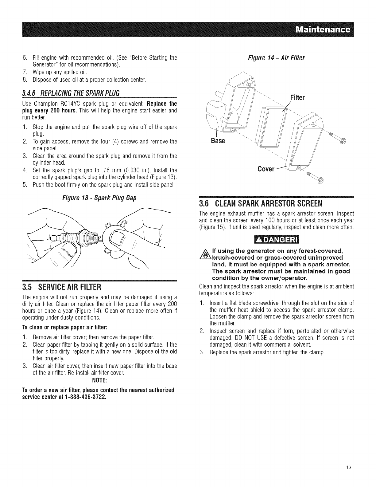
Figure 14- Air Filter
3.4.6 REPLACINGTHESPARKPLUG
Use Champion RC14YCspark plug or equivalent. Replace the
plugevery 200 hours.This wilt help the engine start easierand
run better.
1. Stopthe engineand pull the spark plug wire off of the spark
plug.
2. Togain access, removethe four (4) screws and removethe
side panel.
3. Cleanthe area aroundthe spark plug and remove it from the
cylinder head.
4. Set the spark plug's gap to .76 mm (0.030 in.). Install the
correctly gappedsparkplug intothe cylinderhead(Figure13).
5. Pushthe bootfirmly on the sparkplug and install side panel.
Figure 13 - Spark Plug Gap
3.5 SERVICEAIRFILTER
Theenginewilt not run properlyand may be damaged if usinga
dirty air filter. Cleanor replacethe air filter paperfilter every 200
hours or once a year (Figure14). Cleanor replace more often if
operatingunderdusty conditions.
Tocleanor replacepaperair filter:
1. Removeairfilter cover;then removethe paperfilter.
2. Cleanpaperfilter bytappingit gentlyon a solid surface. If the
filter is too dirty, replaceit with a newone. Disposeof theold
filter properly.
3. Cleanairfilter cover,then insert new paperfilter into the base
of the airfilter.Re-installair filter cover.
NOTE:
Filter
Base
Covel
3.6 CLEANSPARKARRESTORSCREEN
The engineexhaustmuffler has a spark arrestor screen. Inspect
and cleanthe screen every 100 hours or at least onceeachyear
(Figure15). If unit is usedregularly,inspectand cleanmore often.
i_lf using the generator on any forest=covered,
brush=covered or grass=covered unimproved
land, it must be equipped with a spark arrestor.
The spark arrestor must be maintained in good
condition by the owner/operator.
Cleanandinspectthe sparkarrestorwhentheengineis at ambient
temperatureasfollows:
1. Insert a flat blade screwdriverthrough the slot on the side of
the muffler heat shield to access the spark arrestor clamp.
Loosenthe clamp and removethe spark arrestorscreenfrom
themuffler.
2. Inspect screen and replace if torn, perforated or otherwise
damaged. DONOT USEa defective screen. If screen is not
damaged,cleanit with commercialsolvent.
3. Replacethe spark arrestorandtightenthe clamp.
Toorder a new air filter, pleasecontactthe nearestauthorized
servicecenterat 1-888-436-3722.
13
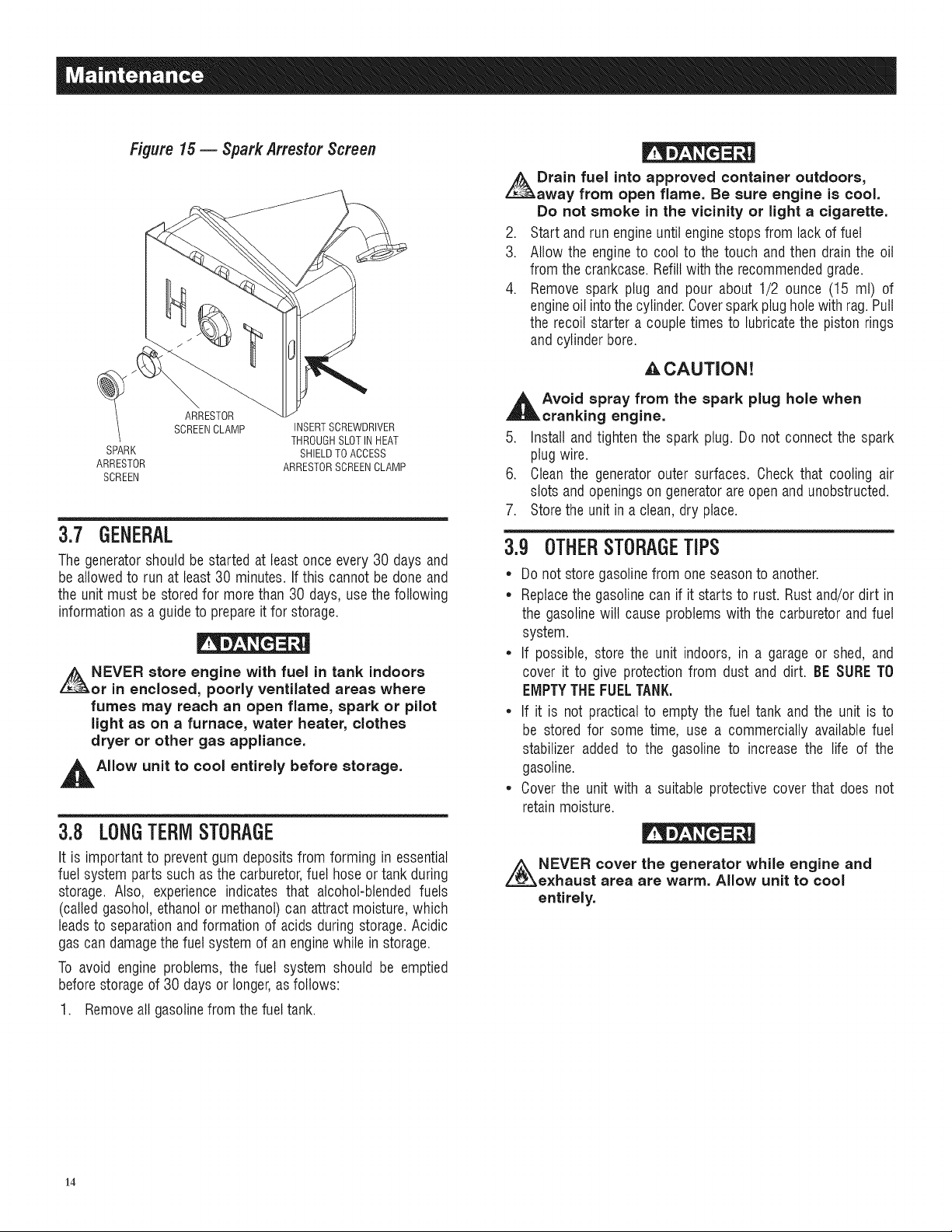
Figure 15 -- Spark Arrestor Screen
Drain fuel into approved container outdoors,
away from open flame. Be sure engine is cool.
Do not smoke in the vicinity or light a cigarette.
2. Start and run engineuntilenginestopsfrom lack of fuel
3. Allow the engineto cool to the touch and then drain the oil
from the crankcase.Refillwith the recommendedgrade.
4. Removespark plug and pour about 1/2 ounce (15 mt) of
engineoil intothecylinder.Coversparkplug holewith rag. Putt
the recoil starter acouple times to lubricatethe piston rings
and cylinderbore.
CAUTION!
ARRESTOR
SCREENCLAMP
SPARK
ARRESTOR
SCREEN
INSERTSCREWDRIVER
THROUGHSLOTINHEAT
SHIELDTO ACCESS
ARRESTORSCREENCLAMP
3.7 GENERAL
Thegeneratorshould be started at leastonce every 30 days and
be allowedto run at least30 minutes.If this cannot be done and
the unit must be stored for morethan 30 days, use thefollowing
informationas a guideto prepareit for storage.
NEVER store engine with fuel in tank indoors
or in enclosed, poorly ventilated areas where
fumes may reach an open flame, spark or pilot
light as on a furnace, water heater, clothes
dryer or other gas appliance.
_t Allow unit to cool entirely before storage.
3.8 LONGTERMSTORAGE
It is importantto preventgum deposits from forming in essential
fuel systemparts such asthe carburetor,fuel hoseortank during
storage. Also, experience indicates that alcohol-blendedfuels
(calledgasohol,ethanol or methanol)can attract moisture,which
leadsto separationand formation of acids during storage.Acidic
gas candamagethefuel system of an enginewhile in storage.
To avoid engineproblems, the fuel system should be emptied
beforestorageof 30 days or longer,asfollows:
1. Removeallgasolinefrom thefuel tank.
_t void spray from the spark plug hole when
cranking engine.
5. Install and tighten the spark plug. Do not connect the spark
plug wire.
6. Cleanthe generatorouter surfaces. Check that cooling air
slots andopeningson generatorareopen andunobstructed.
7. Storethe unit in a clean, dry place.
3.9 OTHERSTORAGETiPS
* Do not store gasolinefrom oneseasonto another.
* Replacethe gasolinecan if it starts to rust. Rustand/or dirt in
the gasolinewill cause problems with the carburetorand fuel
system.
* If possible, store the unit indoors, in a garage or shed, and
cover it to give protectionfrom dust and dirt. BESURETO
EMPTYTHEFUELTANK.
* If it is not practical to emptythe fuel tank andthe unit is to
be stored for some time, use a commercially availablefuel
stabilizer added to the gasoline to increase the life of the
gasoline.
* Coverthe unit with a suitable protective cover that does not
retainmoisture.
i_NEVER cover the generator while engine and
exhaust area are warm. Allow unit to cool
entirely.
14
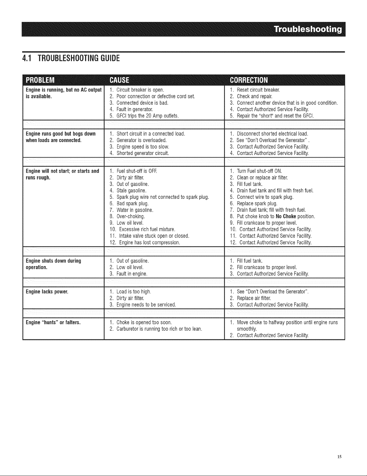
4.1 TBOUBLESHOOTINGGUIDE
Engineis running,but noAC output
is available.
1. Circuit breakeris open.
2. Poor connectionor defectivecord set.
3. Connecteddevice is bad.
4. Faultin generator.
5. GFCItrips the 20 Amp outlets.
! I
1. Resetcircuit breaker.
2. Checkand repair.
3. Connectanotherdevicethat is in good condition.
4. ContactAuthorizedService Facility.
5. Repairthe"short" and reset the GFCI.
Engine runs good but bogs down 1. Short circuit in a connectedload. 1. Disconnectshorted electricalload.
when loadsare connected. 2. Generatoris overloaded. 2. See"Don'tOverloadthe Generator".
3. Enginespeedis too slow. 3. ContactAuthorizedServiceFacility.
4. Shorted generatorcircuit. 4. ContactAuthorizedService Facility.
Enginewill not start; or starts and 1. Fuelshut-off is OFF. 1. TurnFuelshut-off ON.
runsrough. 2. Dirtyair filter. 2. Cleanor replaceairfilter.
3. Out of gasoline. 3. Fillfuel tank.
4. Stale gasoline. 4. Drainfuel tank andfill with fresh fuel.
5. Sparkplug wire not connectedto spark plug. 5. Connectwire to spark plug.
6. Badsparkplug.
7. Waterin gasoline.
8. Over-choking.
9. Low oil level.
10. Excessiverich fuel mixture.
11. Intakevalvestuck open or closed.
12. Enginehas lost compression.
6. Replacesparkplug.
7. Drainfuel tank; fill with fresh fuel.
8. Put choke knobto NoChokeposition.
9. Fill crankcaseto proper level.
10. Contact AuthorizedServiceFacility.
11. Contact AuthorizedServiceFacility.
12. Contact AuthorizedServiceFacility.
Engineshuts downduring 1. Out of gasoline. 1. Fillfuel tank.
operation. 2. Low oil level. 2. Fill crankcaseto proper level.
3. Faultin engine. 3. ContactAuthorizedService Facility.
Engine lacks power. 1. Load is too high. 1. See"Don'tOverloadthe Generator".
2. Dirty air filter. 2. Replaceairfilter.
3. Engineneedsto beserviced. 3. ContactAuthorizedServiceFacility.
.
=
Engine "hunts" or falters. 1. Chokeis openedtoo soon. 1. Move choke to halfway position until engineruns
2. Carburetoris runningtoo rich or too lean. smoothly.
2. ContactAuthorizedService Facility.
15

16

17

EM/$$/ONWARRANTYFOREPACERTIFIEDEQUIPMENT
U,S, EPA EMiSSiON CONTROL WARRANTY STATEMENT
YOUR WARRANTY RIGHTS AND OBLiGATiONS
TheUnited StatesEnvironmentalProtectionAgency (EPA)and GeneracPowerSystems,Inc. (Generac)are pleasedto explainthe Emission Control
SystemWarranty (ECSWarranty) on your new 2011 and laterequipment.New equipmentthat use small spark-ignitedenginesmust bedesigned,built,
andequipped to meet stringentanti-smog standardsfor the federal government.Generacwill warrantthe emission control system on your equipment
for the period of time listed belowprovidedthere has beenno abuse, neglect,unapprovedmodificationor improper maintenanceof your equipment.
Theemission control system on this equipmentincludes all components whose failurewould increasethe emissionsof anyregulatedpollutant.These
componentsare listed in the EmissionsInformation section ofthis manual.
MANUFACTURER'S WARRANTY COVERAGE:
This ECSWarranty is validfor two years,or for the same period as specifiedin the GeneracLimited Warranty,whicheveris longer.Forequipmentwith
hourmeters,the warranty period is anumber of hours equalto halfthe UsefulLifeto whichthe equipmentis certified, or the warrantyperiod specified
abovein years, whicheveris less.TheUseful Life can befound on the EmissionControlLabel on the engine.If, during suchwarranty period,any
emission-relatedpart on your equipmentisfound to be defectivein materialsor workmanship, repairs or replacementwill be performed by aGenerac
AuthorizedWarrantyServiceDealer.
OWNER'S WARRANTY RESPONSiBiLiTiES:
Asthe equipmentowner,you are responsiblefor the completion of all requiredmaintenanceas listed in your factory suppliedOwner'sManual.For
warranty purposes,Generacrecommendsthat you retainall receiptscovering maintenanceon your generator,butGeneraccannotdenywarranty
solelydueto the lack of receipts.
Youshould beaware that Generacmay denyanyand/or all warrantycoverageor responsibility if your equipment,or apart!component thereof,has
failed due to abuse,neglect, impropermaintenance,or unapprovedmodifications.
Youare responsible for contactingaGeoeracAuthorized Warranty Dealer as soonas a problemoccurs.Thewarranty repairsshouldbe
completed in a reasonableamount oftime, not to exceed 30 days.
Warrantyservice can bearrangedby contacting eitheryour sellingdealeror aGeneracAuthorizedWarranty ServiceDealer.Tolocate the Generac
AuthorizedWarrantyServiceDealernearestyou, call ourtoll free numberbelow, or email emissions@generac.com.
1-800-333-1322
IMPORTANTNOTE:This warranty statementexplainsyour rights and obligationsunderthe Emission ControlSystem Warranty,which is providedto
you by Generacpursuantto federal law. Seealsothe "GeneracLimitedWarrantiesfor GeneracPowerSystems,Inc.," which is enclosedherewith on a
separatesheet,also providedto you byGenerac.Notethat this warranty shall not apply to any incidental,consequentialor indirect damagescaused
bydefects in materials or workmanship or any delayin repairor replacementof the defectivepart(s). This warranty is in place of all other warranties,
expressedor implied.Specifically,Generacmakesno other warrantiesas to the merchantabilityor fitness for a particular purpose.Any implied
warrantieswhich areallowed by law, shallbe limited in durationto the terms of the expresswarranty providedherein.Somestates do not allow
limitationson how long an implied warrantylasts, so the abovelimitation may not applyto you.
TheECSWarrantyappliesonly to the emissioncontrol system of your newequipment. Boththe ECSWarrantyandthe GeneracWarrantydescribe
importantrights and obligationswith respectto your new engine.
Warrantyservice can beperformed onlyby a GeneracAuthorizedWarrantyServiceFacility.When requestingwarranty service, evidencemust be
presentedshowingthe date ofthe saleto the originalpurchaser/owner.
Ifyou have any questionsregardingyour warranty rights andresponsibilities,you should contact Generacatthe following address:
ATTENTION WARRANTY DEPARTMENT
GENERAC POWER SYSTEMS, INC.
P.O. BOX 297 * WHITEWATER, Wi 53190
PartI of 2
PartNo. 0J3335A Rev.A 11/11
18
EM/SS/ONWARRANTYFOREPACERTIFIEDEQUIPMENT
EMiSSiON CONTROL SYSTEM WARRANTY
EmissionControl SystemWarranty (ECSWarranty)for equipmentusing small spark-ignited engines:
(a) Applicability:This warranty shall applyto equipmentthat usessmall off-road engines.The ECSWarrantyperiodshall beginon the datethe new
equipmentis purchasedby/deliveredto itsoriginal, end-usepurchaser/ownerandshall continue for the lesserof:
(1) Theperiodof time specified in the GeneracLimited Warrantyenclosedherewith,but notless than 24 months,or
(2) Forenginesequippedwith hour meters,a numberof operating hoursequal to half of the engine'suseful life. The usefullifeis specified on the
EmissionsControl Labelon the engine.
(b) GeneralEmissionsWarranty Coverage:Generacwarrantsto the original,end-usepurchaser/ownerof the new engineor equipment andto each
subsequentpurchaser/ownerthat the ECSwhen installedwas:
(1) Designed,built andequippedsoas to conform with all applicableregulations;and
(2) Freefrom defectsin materialsand workmanship which causethe failure of a warrantedpart at anytime duringthe ECSWarrantyPeriod.
(c) Thewarranty on emissions-relatedparts will be interpretedasfollows:
(1) Anywarranted part that is not scheduledfor replacementas requiredmaintenancein the Owner'sManual shall bewarranted forthe ECS
WarrantyPeriod.If any such partfails duringthe ECSWarranty Period,it shall be repairedor replacedby Generacaccordingto Subsection
(4) below.Any such part repairedor replacedunderthe ECSWarrantyshall bewarranted for the remainderofthe ECSWarranty Period.
(2) Anywarranted part that is scheduled onlyfor regularinspection asspecifiedin the Owner'sManualshall be warrantedfor the ECSWarranty
Period.A statementin the Owner's Manualto the effect of "repairor replace asnecessary"shall not reducethe ECSWarrantyPeriod.Any
such part repairedorreplacedunderthe ECSWarrantyshall be warrantedfor the remainderofthe ECSWarrantyPeriod.
(3) Anywarranted part that is scheduledfor replacementasrequired maintenancein the Owner'sManualshall be warrantedfor the period of time
priorto first scheduled replacementpointfor thatpart. Ifthe part fails prior to the first scheduled replacement,the part shall be repairedor
replacedby Generacaccordingto Subsection(4) below.Any such emissions-relatedpart repairedor replacedunderthe ECSwarranty shall
bewarrantedfor the remainderof the period prior to the first scheduledreplacementpoint for that part.
(4) Repairor replacementof any warranted,emissions-relatedpart underthis ECSWarranty shall beperformed atno charge to the owner ata
GeneracAuthorizedWarrantyServiceFacility.
(5) Notwithstandingthe provisions of subsection (4) above,warranty services or repairsmust be providedat GeneracAuthorizedService
Facilities.
(6) Whenthe engineis inspectedby a GeneracAuthorizedWarrantyServiceFacility,the purchaser/ownershall notbe heldresponsiblefor
diagnosticcosts if the repairis deemedwarrantable.
(7) Throughoutthe ECSWarrantyPeriod,Generacshall maintaina supply of warranted emission-relatedparts sufficient to meetthe expected
demandfor such parts.
(8) AnyGeneracauthorizedand approvedemission-relatedreplacementparts may beused in the performanceof any ECSWarrantymaintenance
or repairsandwill beprovidedwithout chargeto the purchaser/owner.Such useshall not reduceGenerac'sECSWarrantyobligations.
(9) No modifications,other than those explicitlyapproved by Generac,may be madeto the generator.Unapprovedmodificationsvoid this ECS
Warrantyand shall be sufficient groundfor disallowingan ECSWarrantyclaim.
(10) Generacshall not be heldliablehereunderforfailures of any non-authorizedreplacementparts, or failures of anyauthorizedparts caused by
the useof non-authorizedreplacementparts.
EMISSION RELATED PARTS MAY iNCLUDE THE FOLLOWING (IF EQUIPPED):
1) FUELMETERINGSYSTEM 3) IGNITIONSYSTEM
A. CARBURETORANDINTERNALPARTS A. SPARKPLUGS
B. FUELTANK!CAP B. IGNITtONCOILS/MODULE
C. FUELLINES 4) AIRINJECTIONSYSTEM
D. EVAPORATIVEVENTLINES A. PULSEAIRVALVE
E. REGULATOR(GASEOUSFUELS) 5) EXHAUSTSYSTEM
2) AIRINDUCTIONSYSTEM A. CATALYST
A. INTAKEMANIFOLD B. EXHAUSTMANIFOLD
B. AIRFILTER
Part 2 of 2
PartNo. OJ3335ARev.A 11/11
19
 Loading...