

Page 1
Genelec S30D
Operating
Digital Monitoring System
Manual
Page 2

S30D Digital Monitoring System
1. General description1. General description
1. General description
1. General description1. General description
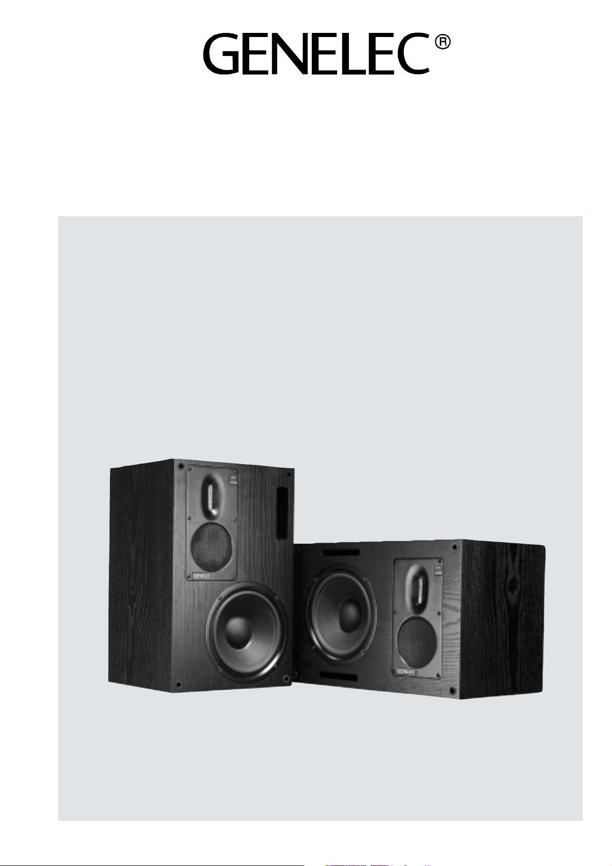
The Genelec S30D is a three-way Digital Monitoring System including a
digital audio interface, balanced analog audio input, loudspeaker drivers, speaker enclosure, multiple power amplifiers and active, low level
crossovers. All these are carefully
aligned and housed within the loudspeaker cabinet.
Featuring a 96 kHz/24-bit digital audio interface and a proprietary ribbon
tweeter capable of reproducing up to
50 kHz acoustic output, the S30D is
a no compromise design. The fast,
low distortion amplifiers are capable
of driving a stereo system to peak
output levels in excess of 122 dB
SPL at 1 m with program signals. Versatile crossover controls allow for precise matching of the speaker system
to different acoustic conditions. Designed for relatively small control
rooms and available in vertical and
horizontal versions, this system is
ideal for multichannel digital workstations, mastering work, general purpose broadcasting and television studios, post production facilities and
mobile recording vehicles. The high
output and absolute reproduction
accuracy make the S30D an ultimate
nearfield monitor in recording studios.
2. Digital audio2. Digital audio
2. Digital audio
2. Digital audio2. Digital audio
The quality of a digital audio signal is
defined by two parameters: word
length and sampling rate. The word
length defines how precisely the audio signal is represented. Studio recording systems use word lengths of
20 bits and above, typically 24 bits.
The sampling rate determines what
frequencies can be represented in
the digital audio signal. A higher sampling rate allows higher frequencies
to be recorded.
Converting the digital presentation to
an analog signal involves potential
sources of error. The digital-to-analog converter may have inferior per-
formance. It may be misaligned with
the amplifiers. The interface between
the converter and the amplifier may
distort the signal or it may change the
frequency balance. Genelec S30D
solves all of these problems. The alignment of the whole system is carefully
balanced to ensure precise monitoring of the digital signal.
3. Integrated construction3. Integrated construction
3. Integrated construction
3. Integrated construction3. Integrated construction
As the digital interface and amplifiers are built into the speaker enclosure, the only connections required
are the mains supply and the digital
(or analog) input signal, making the
S30D very easy to set up and use.
The rugged amplifier is mounted into
the enclosure with vibration isolators
which act also as quick release hinges making possible maintenance
operations very easy and straightforward. The speaker cabinet is constructed of veneered MDF, which is
heavily braced to eliminate structural
resonances.
Digital interfaceDigital interface
Digital interface
Digital interfaceDigital interface
The digital audio interface consists
of a digital audio receiver and a digital-to-analog converter (D/A converter). The digital input accepts an AES/
EBU digital audio signal having a word
length up to 24 bits. With an impedance adapter, the S30D can also accept SP-DIF signal. Digital thru allows the digital audio signal to be retransmitted to other S30D loudspeakers and digital audio equipment.
Crossover filtersCrossover filters
Crossover filters
Crossover filtersCrossover filters
The crossover frequencies of the active crossover network are 420 Hz
and 4 kHz. Special calibrated controls are included in the crossover to
reach uniform frequency balance in
different acoustic conditions. A high
pass filter is included in the LF channel to protect the woofer from subsonic signals. Variable level control
allows for accurate level matching to
the digital or analog signals.
AmplifiersAmplifiers
Amplifiers
AmplifiersAmplifiers
The bass, midrange and treble amplifiers each produce 120 W of short
term power with very low THD and IM
distortion. Special attention is paid to
electronics design to obtain the best
possible subjective sound quality.
The output impedance of the woofer
amplifier is negative to improve
acoustic transient response. Drivers
and amplifiers are also protected from
thermal overload.
DriversDrivers
Drivers
DriversDrivers
The 210 mm (8") woofer is loaded with
a 24 liters (0.85 cu.ft.) vented cabinet. The woofer has a very large magnet and a long linear excursion capability. These are needed to reproduce low frequencies with high efficiency and acoustic output (SPL) in a
small enclosure. The -3dB point is 35
Hz and the low frequency response
extends down to 31 Hz (-6dB).
A carefully designed 80 mm cone
driver, sealed in a cast aluminum alloy housing, reproduces the critical
midrange frequencies where the ear
is the most sensitive. To minimize
coloration the diaphgram is specially
impregnated. As a result, the
midrange driver’s response actually
extends well beyond the range required by the crossovers.
The high frequency driver is a proprietary ribbon tweeter with a moving
mass of only 32 mg and frequency
response extending up to 50 kHz.
The dispersion characteristics of both
the tweeter and midrange driver are
matched for constant tonal balance
in different rooms.
4. Installation4. Installation
4. Installation
4. Installation4. Installation
Every Genelec S30D is delivered with
a mains cable and an Operating Manual. Signal cables are not included.
After unpacking, check that the mains
voltage selector (see figure 2) is correctly set for your local mains volt-
Page 3

age, and place the loudspeakers at
their listening position, taking note of
the reference axis (see figure 1). The
reference axis should be aimed directly at the listening position. Ensure that the mains switches are off
and connect the mains cables.
How to set up for digital signalsHow to set up for digital signals
How to set up for digital signals
How to set up for digital signalsHow to set up for digital signals
Connect a digital audio interface cable to your digital audio source. You
can identify the right connector on
your audio source by looking for the
words “Digital Output” or “AES/EBU
OUT”. Make absolutely sure that the
connectors are carrying the AES/EBU
formatted digital audio signal.
ER ER
ER connect an analog signal cable to
ER ER
NEV-NEV-
NEV-
NEV-NEV-
S30D's digital input connector!
Connect the digital signal cable to
the "DIGITAL INPUT" female XLR connector on a S30D (see figure 2). Next
connect a second signal cable from
speaker's "DIGITAL THRU" male XLR
connector to the "DIGITAL INPUT"
connector of another S30D as shown
in Figure 3 below. You can daisy-chain
practically any number of S30D's in
this manner. Figure 4 overleaf shows
an example of a cabling scheme for
a digital 5.1 channel console.
to play "Left (A)", "Right (B)" or
"Left+Right (A+B)" channel.
Adjust the desired maximum SPL at
1m for a full scale digital signal using
the "DIGITAL LEVEL" switches. This
compensates for differing amounts
of headroom on the digital signal and
enables the speaker to work at its
maximum SPL if required. The "DIGITAL LEVEL" can be set to 112, 100 or
88 dB SPL at 1m with a full scale sine
wave digital signal.
The "LEVEL CONTROL" trimmer adjusts the level of both the digital and
analog signals. Use this trimmer to
give the digital level an extra 0 to -12
dB attenuation in addition to the "DIGITAL LEVEL" switches. Combining
these makes it possible to adjust the
maximum SPL at 1m for a full scale
sinusoidal digital signal anywhere between 112 dB and 76 dB.
Switch on the mains power and feed
an AES/EBU digital signal to the sys-
Use the "CHANNEL SELECT" switches to select loudspeaker mode. Any
S30D in the chain can be designated
Figure 2: S30D backpanel
Figure 1: S30D outer dimensions, with the
reference axis located at the tweeter axis.
Figure 3. Using the "DIGITAL IN" and "DIGITAL THRU" connectors in a digital setup
Page 4

tem. When the S30D detects a digital
signal it switches automatically to the
digital input, and the mode LED turns
yellow. The S30D will switch back to
the analog input if significant errors
are detected in the digital audio or
the digital signal is not present. The
mode LED indicates this by turning
green. If the LED turns red, it indicates an error in the digital signal.
How to set up for analog signalsHow to set up for analog signals
How to set up for analog signals
How to set up for analog signalsHow to set up for analog signals
Turn all mains switches off and remove the digital audio cables. Run
balanced XLR cables from your line
level analog audio source to the "ANALOG INPUT" XLR connector on each
S30D unit.
Switch on the power and observe that
the mode indicator LEDs should turn
green. The output levels can be adjusted at the "LEVEL CONTROL" trimmer.
Figure 4. Cabling scheme for a 5.1 channel digital console
Setting tone controlsSetting tone controls
Setting tone controls
Setting tone controlsSetting tone controls
The response of the system may have
to be adjusted to match the acoustic
environment. The adjustment is done
by setting the tone control switches
on the rear panel. The tone controls
are in five groups: Treble, Mid and
Bass Level, which work in 1 dB steps
and Bass Tilt and Bass Roll-Off, which
work in 2 dB steps. The factory settings for these are 'ALL OFF' to give
a flat anechoic response. See Figure
6 for suggested tone control settings
in differing acoustic environments.
Figure 7 shows the effect of the controls on the anechoic response. Always start adjustment by setting all
switches to "OFF" position. Then set
only one switch to "ON" to select the
required response curve. To obtain
an accurate attenuation value, no more
than one switch within a switch group
should be set to "ON" at the same
time.
Figure 5. Cabling scheme for analog stereo setup
noitisoP
gnitnuoMrekaepS
ciohcenatalF
esnopser
anignidnatseerF
moordepmad
anignidnatseerF
moortnarebrever
ssaB
ffo-lloR
enoNenoNenoNenoNenoN
enoNBd2-enoNenoNenoN
enoNBd2-Bd2-enoNenoN
ssaB
tliT
ssaB
leveL
egnardiM
leveL
elberT
leveL
5. Monitor placement5. Monitor placement
5. Monitor placement
5. Monitor placement5. Monitor placement
Console top mountingConsole top mounting
Console top mounting
Console top mountingConsole top mounting
Avoid mounting Genelec S30D monitors directly on the console top. Instead, position the speakers slightly
behind the console by using floor
stands or wall mounts. This minimizes sound colouring reflections from
the console surface.
anidetnuomtiffoS
llawmoorlortnoc
renrocanIBd2-Bd2-Bd2-enoNenoN
Figure 6. Suggested tone control settings for various acoustic environments
Placement in a roomPlacement in a room
Placement in a room
Placement in a roomPlacement in a room
enoNenoNBd4-enoNenoN
located at identical distance from the
listener. When placed in a room monTo produce a true and accurate stereo or multichannel image the monitors must have exactly similar frequency responses, and they shall be
itor responses change due to reflec-
tions of the sound waves from the
room’s boundaries. Place the moni-
tors at the same height and also at
Page 5

the same distance from the front and
50
55
60
65
70
100k
10k
20k
30k 40k 50k
60k 70k
80k
Hz
S30D 19.1.2000
Mic. B&K 4135 1/4"
dBr
side walls so that reflections, and
therefore changes to the frequency
response, are similar. Smaller objects,
such as equipment racks also cause
reflections and disturb the imaging,
so they too should be placed symmetrically in the room.
To avoid differences in low frequency
responses due to reflections from the
front wall, the monitors should be
placed either nearer than 1m or further than 3m from the front wall. Placement close to the front wall (<1m) will
boost low frequencies, and the tone
controls should be adjusted appropriately (see figure 6).
S30D units may only be done by qualified service personnel.
7. T7. T
rr
oubleshootingoubleshooting
7. T
r
oubleshooting
7. T7. T
rr
oubleshootingoubleshooting
To help you solve any problems, here
are a few pointers:
• Make sure that your audio
signal source has been set
to transmit the audio to the AES/
EBU output.
• Make sure the digital cables are
specified for use with AES/EBU
digital audio signals and properly
connected at both ends.
8. Safety considerations8. Safety considerations
8. Safety considerations
8. Safety considerations8. Safety considerations
Genelec S30D has been designed in
accordance with international safety
standards. To ensure safe operation
and to maintain the instrument in safe
operating condition, the following
warnings and cautions must be observed:
• Servicing and adjustment may
only be performed by qualified
service personnel.
• Do not use this product with an
unearthed mains cable as this may
compromise electrical safety.
The monitors should be aimed toward
the listening position. This maximizes the ratio of direct sound to reflected sound and the listener is able to
hear more of the material and less of
the room effects. Subjectively this is
perceived as cleaner sound and superior imaging.
• Make sure the LED turns yellow
as you plug in the digital audio cable to the S30D unit. If this is not
the case, go back to your audio
source and check once more that
the right output is selected. If the
LED stays green you do not have
a valid digital audio carrier on the
cable.
6. Maintenance6. Maintenance
6. Maintenance
6. Maintenance6. Maintenance
• If you see the LED flashing red
colour, check your cabling. Red coThere are no user serviceable parts in
the unit. Maintenance or repair of the
Mic. B&K 4133 1/2"
dBr
90
85
80
90
85
80
Figure 7. The effect of 'treble tilt', 'bass tilt' and 'bass roll-off'
controls in free field.
BASS TILT
BASS LEVEL
90
85
80
75
BASS ROLL-OFF
20 20k50 100 200 500
MIDRANGE LEVEL
1k
lour indicates a bit error in trans-
mission.
S30D 19.1.2000
TREBLE LEVEL
5k
2k
10k
• This equipment is capable of producing sound pressure levels in
excess of 85 dB, which may cause
permanent hearing damage.
• Free flow of air behind the loudspeaker is necessary to maintain
sufficient cooling. Do not obstruct
airflow around the loudspeakers.
• Do not insert any objects through
the bass reflex port(s) on the face
of the unit, as this may damage the
drive units inside the loudspeaker.
• Do not run an analog audio signal to the digital input XLR connector. Doing so may overload your
audio equipment output and cause
them permanent damage.
9. Guarantee9. Guarantee
9. Guarantee
9. Guarantee9. Guarantee
This product is guaranteed for a period of ONE year against faults in materials or workmanship. Refer to sup-
Hz
plier for full sales and guarantee
terms.
Mic. B&K 4133 1/2"
dBr
95
90
85
80
75
70
65
60
55
50
20
50
Figure 8. Horizontal directivity characteristics and power
response of S30D in its vertical configuration measured at 1m in
free field.
100
200 500
1k 2k 5k
S30D 19.1.2000
0° 30°
15°
45°
10k
Hz
60°
20k
Figure 9. The on-axis free field response of the S30D between
10 and 100 kHz.
Page 6

SYSTEM SPECIFICASYSTEM SPECIFICA
SYSTEM SPECIFICA
SYSTEM SPECIFICASYSTEM SPECIFICA
TIONSTIONS
TIONS
TIONSTIONS
CROSSOVER SECTIONCROSSOVER SECTION
CROSSOVER SECTION
CROSSOVER SECTIONCROSSOVER SECTION
DIGITDIGIT
DIGIT
DIGITDIGIT
AL SECTIONAL SECTION
AL SECTION
AL SECTIONAL SECTION
Lower cut-off frequency, -3 dB: <35 Hz
Upper cut-off frequency, -3 dB: >50 kHz
Free field frequency response of system:
Maximum short term sine wave acoustic output on
axis in half space, averaged from 100 Hz to 3 kHz:
Maximum long term RMS acoustic output in same
conditions with IEC-weighted noise (limited by
driver unit protection circuit):
Maximum peak acoustic output per pair on top of
console, @ 1m from the engineer with music
material: >122 dB
Self generated noise level in free field @ 1m on
axis: <10 dB (A-weighted)
Harmonic distortion at 90 dB SPL at 1m on axis:
Drivers: Bass 210 mm cone
Weight: 20 kg (44 lb)
Dimensions: Height 495 mm (19
36 Hz - 48 kHz (±2.5 dB)
>111 dB SPL
@1m
>117 dB SPL
@0.5m
@1m >102 dB SPL
>108 dB SPL
@0.5m
<200 Hz <2%
freq.
freq. >200 Hz <1%
Midrange 80 mm cone
Treble 9x65 mm
Width 320 mm (12 5/8")
Depth 290 mm (11 7/16")
ribbon
1
/2")
Analog input connector: XLR female
Input impedance: 10 kOhm
Input level for maximum short term output of
111 dB SPL @1m:
Output level for -6 dBu analog input:
Subsonic filter below 33 Hz : 18 dB/octave
Ultrasonic filter above 60kHz: 12dB/octave
Crossover frequency:
Crossover acoustical slopes:
Crossover level control operating range in 1 dB
steps:
Bass roll-off control in 2 dB steps:
Bass tilt control in 2 dB steps:
The 'CAL' position is with all tone controls set to
'off' and level control to maximum.
OPTIONSOPTIONS
OPTIONS
OPTIONSOPTIONS
Flight case Order Code 1001-401
Wall mount Order Code 1010-404-V/H*
Floor stand Order Code 1010-405-V/H*
Grille Order Code 1010-409
*V=Vertical (for S30D V), H=Horizontal (for S30D H)
variable from +17 to +5 dBu
variable from 88 to 100 dB SPL@1m
bass/mid 420 Hz
mid/treble 4 kHz
18 - 24 dB/octave
bass from 0 to -6 dB
mid from 0 to -6 dB
treble from 0 to -6 dB
from 0 to -8 dB @35 Hz
from 0 to -8 dB @80 Hz
pin1 gnd
pin2 +
pin3 -
Digital input : XLR female
Digital thru output: XLR male
Maximum input word length: 24 bits
Input format: AES/EBU,
Input termination impedance: 110 Ohms*
Input sampling rate:
Jitter resiliance: 0.15 unit intervals
Dynamic range:
De-emphasis: 50/15us, automatic
Recovered clock jitter:
Output level for full scale digital input:
* An optional impedance matching adapter is
required for 75 Ohm signal source.
AMPLIFIER SECTIONAMPLIFIER SECTION
AMPLIFIER SECTION
AMPLIFIER SECTIONAMPLIFIER SECTION
Amplifier output power with an 8 Ohm load (Short
term):
Long term output power is limited by driver unit
protection circuitry.
Slew rate: 80V/µs
Amplifier system distortion at nominal output:
Signal to Noise ratio, referred to full output:
Mains voltage: 100/200V or 115/230V AC
29-100 kHz (no de-emphasis)
44.1 kHz (using de-emphasis)
113dB (A weighted, triangular
PDF dither, 24 bit data)
200 picoseconds RMS typical
variable from 76 to 112 dB
SPL @1m
Bass 120 W
Midrange 120 W
Treble 120 W
THD
SMPTE-IM <0.05%
CCIF-IM <0.05%
DIM 100
Bass >100 dB
Midrange >100 dB
Treble
SP-DIF*
<0.05%
<0.05%
>100 dB
Genelec Oy, Olvitie 5
FIN - 74100 IISALMI, FINLAND
Phone: +358 - 17 - 83881
Telefax: +358 - 17 - 812267
Web: http://www.genelec.com
E-mail: genelec@genelec.com
Genelec Inc, 7 Tech Circle
Natick, MA 01760, USA
Phone: +1 - 508 - 652 - 0900
Fax: +1 - 508 - 652 - 0909
E-mail: genelec@compuserve.com
Voltage operating range: nominal ±10%
Power consumption:
Idle 30W
Full output 200W
Genelec document D0001R001a
COPYRIGHT GENELEC OY 8.2001
All data subject to change without prior notice
 Loading...