

Page 1
S30D
DATA SHEET
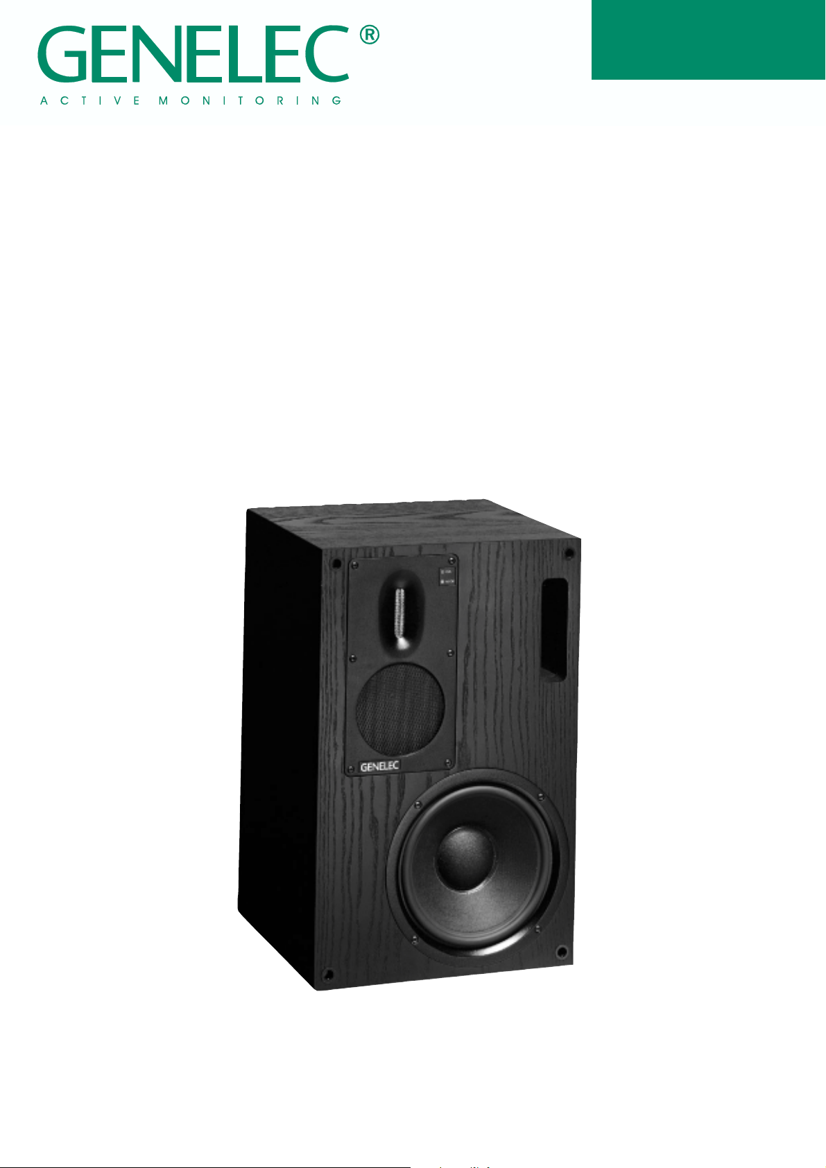
Genelec S30D
Digital Monitoring System
Page 2
S30D Digital Monitoring SystemS30D Digital Monitoring System
S30D Digital Monitoring System
S30D Digital Monitoring SystemS30D Digital Monitoring System
Main features:Main features:
Main features:
Main features:Main features:
AES/EBU digital audio and analog audio
inputs in a single speaker system
Digital audio thru
96 kHz / 24-bit digital audio interface
50 kHz audio output bandwidth for
monitoring of 96 kHz digital audio
Automatic detection of word length and
sampling rate
Perfect level match throughout the system
from D/A converter to power amplifier
outputs
Standard sound level conversion
High system integration
SYSTEM
The Genelec S30D is a three-way
Digital Monitoring System including a digital audio interface, balanced analog audio input, loudspeaker drivers, speaker enclosure, multiple power amplifiers
and active, low level crossovers.
All these are carefully aligned and
housed within the loudspeaker
cabinet.
Featuring a 96 kHz/24-bit digital
audio interface and a proprietary
ribbon tweeter capable of reproducing up to 50 kHz acoustic
output, the S30D is a no compromise design. The fast, low distortion amplifiers are capable of driving a stereo system to peak output levels in excess of 122 dB
SPL at 1 m with program signals.
Versatile crossover controls allow for precise matching of the
speaker system to different
acoustic conditions. Designed for
relatively small control rooms and
available in vertical and horizontal versions, this system is ideal
for multichannel digital workstations, mastering work, general
purpose broadcasting and television studios, post production
facilities and mobile recording
vehicles. The high output and
absolute reproduction accuracy
make the S30D an ultimate
nearfield monitor in recording studios.
DIGITAL AUDIO
The quality of a digital audio signal is defined by two parameters:
word length and sampling rate.
The word length defines how precisely the audio signal is represented. Studio recording systems use word lengths of 20 bits
and above, typically 24 bits.
The sampling rate determines
what frequencies can be represented in the digital audio signal.
A higher sampling rate allows
higher frequencies to be recorded.
Converting the digital presentation to an analog signal involves
potential sources of error. The
digital-to-analog converter may
have inferior performance. It may
be misaligned with the amplifiers.
The interface between the converter and the amplifier may distort the signal or it may change
the frequency balance. Genelec
S30D solves all of these problems. The alignment of the whole
system is carefully balanced to
ensure precise monitoring of the
digital signal.
INTEGRATED
CONSTRUCTION
As the digital interface and amplifiers are built into the speaker
enclosure, the only connections
required are the mains supply
and the digital (or analog) input
signal, making the S30D very
easy to set up and use.
The rugged amplifier is mounted
into the enclosure with vibration
isolators which act also as quick
release hinges making possible
maintenance operations very
easy and straightforward. The
S P E A K E R
C A B I N E T
P o w e r
S u p p ly
c i r c u i t s
T r e b le
M i d r a n g e
B a s s
M a i n s I n p u t
A n a l o g
i n p u t
D i g i t a l
i n p u t
D i g i t a l
t h r u
D i g i t a l
I n t e r f a c e
D i g i t a l L e v e l
L e v e l C o n t r o l
D r i v e r
p r o t e c t i o n
c i r c u i t s
C R O S S O V E R
F I L T E R
A c o u s t i c
c o n t r o l s
P o w e r
O n / O f f
M u t e
P O W E R
A M P L I F I E R S
N e g . o u t p u t
i m p e d a n c e
c i r c u it s
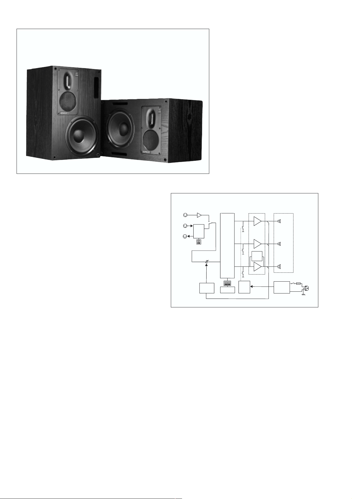
The block diagram showing the digital interface, active crossover
filters, power amplifiers and driver units.
speaker cabinet is constructed
AMPLIFIERS
of veneered MDF, which is heavily
braced to eliminate structural
resonances.
The bass, midrange and treble
amplifiers each produce 120 W of
short term power with very low
DIGITAL INTERFACE
THD and IM distortion. Special
attention is paid to electronics
The digital audio interface consists of a digital audio receiver
and a digital-to-analog converter
(D/A converter). The digital input
accepts an AES/EBU digital audio signal having a word length
up to 24 bits. With an impedance
adapter, the S30D can also ac-
design to obtain the best pos-
sible subjective sound quality.
The output impedance of the
woofer amplifier is negative to
improve acoustic transient re-
sponse. Drivers and amplifiers
are also protected for thermal
overload.
cept SP-DIF signal. Digital thru
allows the digital audio signal to
DRIVERS
be re-transmitted to other S30D
loudspeakers and digital audio
equipment.
The 210 mm ( 8") woofer is loaded
with a 24 liters (0.85 cu.ft.) vented
Page 3

The reference axis is located on
the tweeter driver.
cabinet. The woofer has a very
large magnet and a long linear
excursion capability. These are
needed to reproduce low frequencies with efficiency and high
acoustic output (SPL) in a small
enclosure. The -3dB point is 35
Hz and the low frequency response extends down to 31 Hz.
A carefully designed 80 mm cone
driver, sealed in a cast aluminum
alloy housing, reproduces the
critical midrange frequencies
where the ear is the most sensitive. To minimize coloration the
diaphgram is specially impregnated. As a result, the midrange
driver’s response actually extends well beyond the range required by the crossovers.
Horizontal version S30D H
Vertical version S30D V
The high frequency driver is a
proprietary ribbon tweeter with a
moving mass of only 32 mg and
frequency response extending
up to 50 kHz. The dispersion
characteristics of both the tweeter
and midrange driver are matched
for stabile tonal balance in different rooms.
CROSSOVER FILTERS
The crossover frequencies of the
active crossover network are 420
Hz and 4 kHz. Special calibrated
controls are included in the crossover to reach uniform frequency
balance in different acoustic conditions. The Bass, Mid and Treble
level controls operate in 1 dB
steps. The Bass Tilt and Roll-off
controls have 2 dB steps to allow
refined LF response tailoring. A
high pass filter is included in the
LF channel to protect the woofer
from subsonic signals. Variable
level control allows for accurate
level matching to the digital or
analog signals.
DIGITAL AND ANALOG
SIGNAL MANAGEMENT
The AES-EBU digital signal is fed
into the "DIGITAL INPUT" XLR
connector and carried on to another S30D via the "DIGITAL
THRU" connector. Practically any
number of S30D's can be daisychained in this manner.
When the S30D detects a digital
signal it switches automatically to
the digital input. The S30D will
switch back to the analog input if
significant errors are detected in
the digital audio or the digital signal is not present.
Loudspeaker mode is selected
with "CHANNEL SELECT"
switches on the speaker back-
plate. A speaker can be designated as "Left (A)", "Right (B)" or
"Left+Right (A+B)" channel.
The maximum SPL at 1m for a full
scale digital signal can be adjusted using the "DIGITAL LEVEL"
switches. This compensates for
differing amounts of headroom
on the digital signal and enables
the speaker to work at its maximum SPL if required. The "DIGITAL LEVEL" can be set to 112,
102 or 92 dB SPL at 1m with a full
scale digital signal.
The "LEVEL CONTROL" trimmer
adjusts the level of both the digital
and analog signals. Using this
trimmer the digital level can be
adjusted to give an extra 0 to -12
dB attenuation in addition to the
"DIGITAL LEVEL" switches. This
makes it possible to adjust the
maximum SPL at 1m for a full
scale sinusoidal digital signal anywhere between 112 dB and 70
dB.
The "ANALOG INPUT" XLR connector allows monitoring of analog audio signal.
The unique ribbon tweeter and
the sealed midrange driver are
mounted on a separate chassis
to match the dispersion
characteristics.
S30D backplate, connectors and controls
Page 4

S30D
The upper curve group shows the horizontal directivity characteristics of
S30D in its vertical configuration measured at 1 m. The lower curve shows
the systems power response.
SYSTEM SYSTEM
SYSTEM
SYSTEM SYSTEM
Lower cut-off frequency, -3 dB: <35 Hz
Upper cut-off frequency, -3 dB: >50 kHz
Free field frequency response of system:
Maximum short term sine wave acoustic output on axis in
half space, averaged from 100 Hz to 3 kHz:
Maximum long term RMS acoustic output in same conditions with IEC-weighted noise (limited by driver unit
protection circuit):
Maximum peak acoustic output per pair on top of console,
@ 1m from the engineer with music material:
Self generated noise level in free field @ 1m on axis:
<10 dB (A-weighted)
Harmonic distortion at 90 dB SPL at 1m on axis:
Drivers: Bass 210 mm cone
Weight: 20 kg (44 lb)
Dimensions: Height 495 mm (19 1/2")
The curve above shows the on-axis free field
response of the S30D between 10 and 100 kHz.
SPECIFICATIONSSPECIFICATIONS
SPECIFICATIONS
SPECIFICATIONSSPECIFICATIONS
36 Hz - 48 kHz (±2.5 dB)
@1m >111 dB SPL
@0.5m >117 dB SPL
@1m >102 dB SPL
@0.5m >108 dB SPL
>122 dB SPL
freq. <200 Hz <2%
freq. >200 Hz <1%
Midrange 80 mm cone
Treble 9x65 mm ribbon
Width 320 mm (12 5/8")
Depth 290 mm (11 7/16")
CROSSOVER CROSSOVER
CROSSOVER
CROSSOVER CROSSOVER
Analog input connector: XLR female pin1 gnd
Input impedance: 10 kOhm
Input level for maximum short term output of 111 dB
SPL @1m: variable from +17 to +5 dBu
Output level for -6 dBu analog input:
Subsonic filter below 33 Hz : 18 dB/octave
Ultrasonic filter above 60kHz: 12dB/octave
Crossover frequency:
Crossover acoustical slopes:
Crossover level control operating range in 1 dB steps:
Bass roll-off control in 2 dB steps:
Bass tilt control in 2 dB steps:
The 'CAL' position is with all tone controls set to 'off' and
level control to maximum.
OPTIONSOPTIONS
OPTIONS
OPTIONSOPTIONS
Flight case Order Code 1001-401
Wall mount Order Code 1010-404-V/H*
Floor stand Order Code 1010-405-V/H*
Grille Order Code 1010-409
*V=Vertical (for S30D V), H=Horizontal (for S30D H)
The curves above left show the effect of the 'bass tilt', 'bass level' and
'bass roll-off' controls on the free field response. The curves to the right
show the effect of the treble and midrange 'level' controls.
SECTIONSECTION
SECTION
SECTIONSECTION
pin2 +
pin3 -
variable from 88 to 100 dB
SPL @1m
bass/mid 420 Hz
mid/treble 4 kHz
18 - 24 dB/octave
bass from 0 to -6 dB
mid from 0 to -6 dB
treble from 0 to -6 dB
from 0 to -8 dB @35 Hz
from 0 to -8 dB @80 Hz
DIGITAL SECTIONDIGITAL SECTION
DIGITAL SECTION
DIGITAL SECTIONDIGITAL SECTION
Digital input : XLR female
Digital thru output: XLR male
Maximum input word length: 24 bits
Input format: AES/EBU, SP-DIF
Input termination impedance: 110 Ohms*
Input sampling rate: 29-100 kHz (no de-emphasis)
Jitter resiliance: 0.15 unit intervals
Dynamic range: 113dB (A weighted, triangular
De-emphasis: 50/15us, automatic
Recovered clock jitter: 200 picoseconds RMS typical
Output level for full scale digital input:
* An impedance matching adapter is required for 75 Ohm
signal sources.
AMPLIFIER SECTIONAMPLIFIER SECTION
AMPLIFIER SECTION
AMPLIFIER SECTIONAMPLIFIER SECTION
Amplifier output power with an 8 Ohm load (Short term):
Long term output power is limited by driver unit protection
circuitry.
Slew rate: 80V/µs
Amplifier system distortion at nominal output:
Signal to Noise ratio, referred to full output:
Mains voltage: 100/200V or 115/230V
Voltage operating range : nominal ±10%
Power consumption: Idle 30W
44.1 kHz (using de-emphasis)
PDF dither, 24 bit data)
variable from 76 to 112 dB
SPL @1m
Bass 120 W
Midrange 120 W
Treble 120 W
THD <0.05%
SMPTE-IM <0.05%
CCIF-IM <0.05%
DIM 100 <0.05%
Bass >100 dB
Midrange >100 dB
Treble >100 dB
Full output 200W
All data subject to change without prior notice.
Genelec Oy, Olvitie 5
FIN - 74100 IISALMI, FINLAND
Phone: +358 - 17 - 813 311
Fax: +358 - 17 - 812 267
E-mail: genelec@genelec.com
Web: http://www.genelec.com
Genelec Document BBAS30D001a COPYRIGHT GENELEC OY 5.2000
Genelec Inc, 7 Tech Circle
Natick, MA 01760, USA
Phone: +1 - 508 - 652 - 0900
Fax: +1 - 508 - 652 - 0909
E-mail: genelec@compuserve.com
 Loading...