

Page 1
HTS6
Operating Manual
Genelec HTS6
Active Subwoofer
Page 2
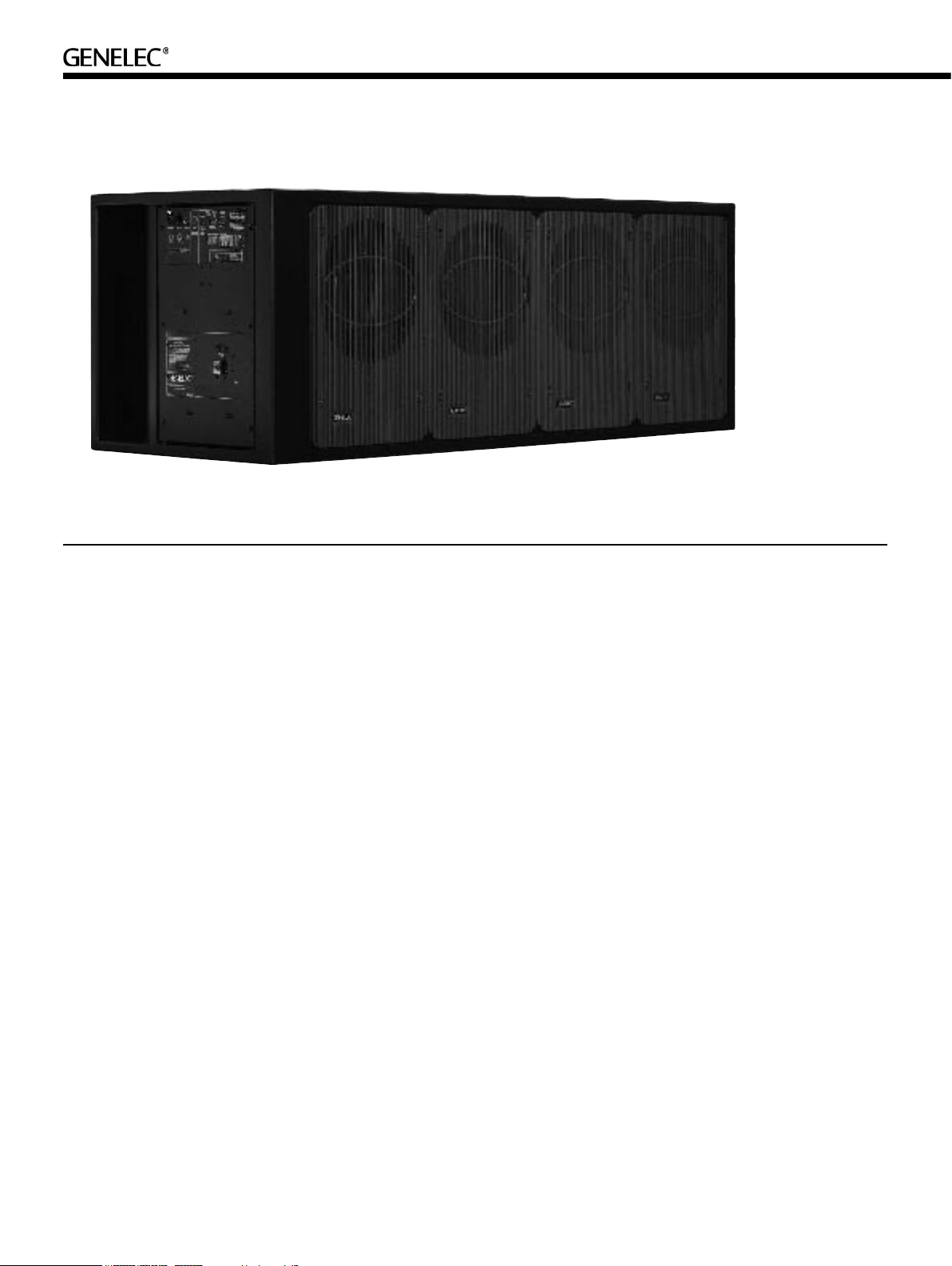
HTS6 Active Subwoofer
General description
Genelec HTS6 is a powerful active subwoofer
designed specially for high quality digital 5.1
channel Home Theater systems. Its 19 to
120 Hz (± 3 dB) frequency range and 124
dB sound pressure output capability are suf-
ficient to handle the most demanding high
SPL applications.
High quality XLR and RCA line level input
connectors and adjustable input sensitiv-
ity provide easy connection to all types of
decoders. Bass roll-off rate and crossover
phase can be adjusted to suit different
acoustical environments and subwoofer
positioning. A “LINK OUT” connector allows
coupling two or more subwoofers together
when very high sound pressure levels are
required. The amplifiers are equipped with
an “AUTOSTART” function for automatic
switching between “STANDBY” and “ON”
modes. Connectors for remote controlled
power “ON/STANDBY” switches are also
provided.
Installation
Each subwoofer is supplied with a mains
cable and an operating manual. Once
unpacked, place the subwoofer in a suitable
location (For more details see the ‘Position-
ing’ section).
Before con ne cting the audio signal s,
ensure that all equipment are switched off.
Check that the subwoofer voltage selector
switch is set to the correct voltage. Audio
input to the subwoofer can be made via
balanced XLR or unbalanced RCA connec-
tor. We recommend the use of balanced
cables and connectors due to their better
noise immunity. Do not use both inputs at
the same time.
The “LINK OUT” connector can be used for
daisy-chaining several subwoofers together
when high SPL is required. Simply connect
a balanced XLR cable from the “LINK OUT”
connector to the “XLR INPUT” connector of
the next subwoofer. See section “Using mul-
tiple subwoofers”.
Once all connections have been made, the
subwoofer and main speakers are ready to
be powered up.
Positioning in the room
The placement of the subwoofer in the room
affects the overall frequency response and
sound level of the system dramatically, as at
low frequencies the effects of the room are
strong. Even a slight change in the subwoof-
er's location can make a marked difference
in the frequency balance and often patient
and methodical experimentation and testing
is needed to find the optimum placement.
The placement will affect the phase dif-
ference between the main monitors and the
subwoofer, and also the bass roll-off rate.
These effects can be compensated by the
use of the controls in the amplifier unit; but
we recommend that at first you leave the
switches untouched and concentrate on find-
ing the position where the subwoofer gives
the smoothest response, and only then use
the controls to fine-tune the balance and
phase alignment between the subwoofer and
the main speakers.
To begin with, place the subwoofer slightly
offset from the center of the fr ont wal l.
The recommended distance to the wall is
less than 90 cm / 36" measured from the
subwoofer's drivers. This position gives
increased acoustic loading (and SPL) due to
the proximity of the front wall and floor. Can-
cellations from the front wall and floor are
also avoided. In a multichannel system the
main speakers should ideally be positioned
Page 3

Figure 2. XLR to RCA connector for
unbalanced operation.
Figure 1. HTS6's connector panel, connectors an d controls.
symmetrically and at an equal distance from
the listening position.
If the frequency balance is not right, try
moving the subwoofer slightly to the left or
right so th at different ro om modes are
excited at different levels. Positioning the
subwoofer close to a corner will boost the
bass level at lower frequencies and may
cause asymmetrical spatial imaging. If you
are using two subwoofers, try placing them
asymmetrically relative to the side walls.
Sometimes moving the subwoofers apart
into the front corners helps with problematic
rear wall reflections and the loss of mutual
coupling is compensated by the bass boost
caused by corner positioning.
Although the HTS6 subwoofer is magneti-
cally shielded, they may cause some picture
distortion if placed near very sensitive video
monitors or computer displays.
Minimum clearances to walls
or other objects
The power amplifiers are attached to the
lower part of the aluminium grilles, which
function as a heatsink. Do not cover the
grilles or place the subwoofer so that there is
less than 10 centimeters (4") of free space in
front of the grilles.
The reflex port and connector panel should
always have a clearance of at least 20 cen-
timeters (8") to any objects to ensure proper
function of the port and cooling for the elec-
tronics attached to the connector panel.
Flush mounting the subwoofer
If the subwoofer is flush mounted into a
wall or a cabinet, it is important to ensure
unrestrict ed airflow from the reflex port
and cooling for the electronic components.
This can be done by making the recess 20
centimeters (8") wider than the subwoofer.
Place the subwoofer into the right end of
the recess with the drivers' side facing the
room. This leaves sufficient 20 centimeters
(8") of free space on the connector panel and
reflex port side. The height and depth of the
recess should not be any bigger than those
needed to fit the subwoofer flush with the
wall surface.
Setting the input sensitivity
The subwoofer requires input sensitivity
alignment to the source to obtain a correctly
balanced system. The input sensitivity con-
trol is located on the connector panel of the
Subwoofer placement Bass Roll-Off
setting
Near to a wall -2 dB
In a corner -6 dB
Flush mounted -2 dB
Table 1. Suggested Bass Ro ll-Off settings
subwoofer. An input voltage of -6 dBu with a
-6 dBu input sensitivity setting will produce
100 dB SPL @ 1m in free field. To obtain a
110 dB SPL output an input voltage of +10
dBu is required when the input sensitivity is
set to 0 dBu.
Setting the Bass Roll-Off
switches
The acoustic response of the subwoofer may
have to be matched to the characteristics of
the room and the positioning in which it will
be used. To adjust the subwoofer to match
these characteristics use the ''Bass Roll-Off'
control switches located on the connector
panel. Table 1 provides some suggestions
for the "Bass Roll-Off" switch settings. When
all roll-off switches are set to "OFF", a flat
anechoic response is obtained.
Setting the phase control
Incorrect phase alignment between main
monitors and subwoofer causes a drop in
the frequency response of the whole system
at the crossover frequency. The graphs on
the following page (Fig. 4) show the effect of
phase difference to the frequency response.
The phase difference between the main
Page 4

Figure 4. The effect of phase difference betwee n the subwoofer a nd the main speakers
Phase Difference: 0˚
120 Hz
Phase Difference: 180˚
120 Hz
Phase Difference: 270˚
120 Hz
Phase Difference: 90˚
120 Hz
Remote
control type
12 V DC
remote
control
External
switch or
relay
Connect only one remote control unit at a time
Table 2. Remote control co nnector pin seque nce
Pole or
contact
+ 1
- 2
Contact 1 3
Contact 2 4
Connect to
remote control
input pin no.
speakers and subwoofer at the listening
position is dependent upon the position of
the subwoofer, so the phase adjustment
should be done only after the preferred posi-
tion is found. Acoustic measuring equipment
is required for accurate system alignment. If
this equipment is not available, the following
coarse phase matching can be applied.
Coarse phase adjustment
method
Configure the processor so that the main
speakers (L, C, R) are set to “small” and
check the subwoofer crossover frequency
setting on your processor. This setting may
be either fixed or variable, consult the operat-
ing manual of your processor.
Connect an audio frequency signalgenera-
tor to one of the front L, C or R input channels
used in the system.
Set the frequency generator to the same
frequenc y as the subwoofer crossover
frequency on your processor.
If a signal generator is not available, you
can use an audio test recording with a suit-
able range of test frequencies. Mute all other
channels and perform the adjustment with
only one of the front speakers playing.
Toggle the -180°
phase switch ‘ON’
and ‘OFF’ and set it
to the position which gives the lowest sound
level at the listening position.
Next toggle the -90°
phase switch ‘ON’ and
‘OFF’, and again set it
to the position which gives the lowest sound
level.
Finally, set the -180°
phase switch to the
opposite setting.
Using multiple subwoofers
The HTS6 is equipped with a “LINK OUT”
connector to provide an easy way of coupling
two or more subwoofers together in high
SPL applications. Connect a XLR cable from
the “LINK OUT” connector of the “master”
HTS6 to which the main monitor channels
are connected, to the “XLR IN” connector of
the other, “slave” subwoofer.
When two subwoofers connected in this
way are positioned close to one another,
ba ss lev el incre ase s b y 6 dB. Th ree
subwoofers give an bass SPL increase of 9,5
dB and four subwoofers 12 dB compared to
a single subwoofer. Adjust the sensitivity con-
trol of all subwoofers in the group to match
the SPL level with the main speakersystem.
Note that the sensitivity setting must be the
same on all subwoofers.
Autostart and remote control
The HTS6 is equipped with an “AUTOSTART”
function, which automatically turns the ampli-
fier to “STANDBY” mode if an input signal has
not been detected for approximately five min-
utes, and back to “ON” mode when the signal
returns. The function can be deactivated by
turning the “AUTOSTART” dip switch to “OFF”.
A two-colour LED on the connector panel indi-
cates the amplifier status: green for “ON” and
yellow for “STANDBY”.
The amplifier mode can also be switched
by a remote control unit connected to the
respective inputs on the amplifier. Two pairs
of connectors are provided, 1 and 2 for a
12 V DC type remote control, and 3 and 4
for an external switch or relay type control.
Do not connect two remote controls to the
subwoofer at the same time. Remote control
overrides the “AUTOSTART” function.
Page 5

Figure 5. The curves above show the
20 cm (8”)
GENELEC
GENELEC GENELEC
GENELEC
f ~ 2-8 Hz
HEAVY WOODEN
OR CONCRETE
WALL
VIBRATION
ISOLATORS
HEAVY
WOODEN
OR
CONCRETE
WALL
ABSORBING
MATERIAL
VIBRATION
ISOLA
TORS
f ~ 2-8 Hz
ABSORBING
MATERIAL
HEAVY
WOODEN
OR
CONCRETE
WALL
VIBRATION
ISOLA
TORS
f ~ 2-8 Hz
harmonic distortion analysis of the HTS6
in free field. In half space the SPL will be 6
dB higher.
Figure 6. Flush mounting the subwoofer. Note t he clearance needed on the reflex port side.
Figure 7. Flush mounting the subwoofer in a
non-absorbing wall.
Figure 8. Correct flush mounting in a semiabsorbing wall.
Automatic protection circuits
The HTS6 is equipped with protection circuits
against speaker driver thermal overload and
amplifier overheating. The protection system
resets automatically so the user only has to
turn the input level down to ensure that it
does not reactivate.
Safety considerations
The HTS6 subwoofer has been designed in
accordance with international safety stand-
ards. However, to ensure safe operation and
maintain the unit in safe operating condition,
the following warnings and cautions must be
observed:
• Do not expose the subwoofer to water
or moisture. Do not place any objects
filled with liquid, such as vases on
the subwoofer or near it.
• Servicing and adjustment must only
be performed by qualified
service personnel.
• Opening the connector panel is
strictly prohibited except by
qualified service personnel.
• Always use a mains power connection
with protective earth. Failing to do
this may lead to personal injury.
• Note that the amplifier is not completely
disconnected from the AC mains
service unless the mains power cord is
removed from the amplifier or the
mains outlet
Warning!
Thi s equipment is capable of delivering
sound pres su re levels in excess of 8 5
dB, which may cause permanent hearing
damage.
Maintenance
No user serviceable parts are inside the
amplifier unit. Any maintenance of the unit
must only be performed by qualified service
personnel.
Guarantee
This product is supplied with a two year guar-
antee against manufacturing faults or defects
that might affect the performance of the unit.
Refer to supplier for full sales and guarantee
terms.
Figure 9.Incorrect flush mounting in a semiabsorbing wall.
Page 6

HTS6 Operating Manual
SYSTEM SPECIFICATIONS
HTS6
Free field frequency response 19 Hz…120 Hz
(+/- 3 dB)
Maximum short te rm sine wave
SPL output avera ged from
30 to 85 Hz, mea sured in
half space at 1 meter 124 dB S PL
Maximum peak SPL output with
random pink nois e, measured
in half space at 1 meter 129 dB SPL
Self generated n oise level in
free field @ 1 m on axis
(A-weighted) 20 dB
Harmonic distort ion @ 105 dB SPL
at @ 1 m on axis in half space 30 … 85 Hz
2nd 2 %
3rd 2 %
Drivers 4 x 305 mm (12 ”)
Weight 120 kg ( 265 lbs)
Dimensions
Height 524 mm (20 5/8”)
Width 1440 mm (56 11/1 6”)*
Depth 558 mm (22”)
* If the subwoofer is fl ush mo unted into a wal l or a cabinet, the recess mu st be 20 cm (8”)
wider than th e subwoo fer to allow suffici ent cle arance f or the reflex port situated at the e nd
of the subwoofer enclosure.
CROSSOVER SECTION
HTS6
Subsonic filter
(18 dB/octave) b elow 19 Hz
Upper bandwidth 120 Hz
Crossover slopes
Lowpass 36 dB/octave
Highpass 12 dB/octave
Midband rejectio n >400 Hz 50 dB
Bass roll-off co ntrol operating From 0 to –6 dB @ 20 Hz
range in 2 dB st eps
Phase matching c ontrol From 0 to 270° @ 85 Hz
in 90° steps
AMPLIFIER SECTION
HTS6
Short term ampli fier output
power (Long term output power
is limited by dr iver unit
protection circu itry) 1000 W
Amplifier system distortion
at nominal outpu t
THD 0.05%
Mains voltage 100/200V
or 115/230V
Power consumption (average)
Idle 60 VA
Full output 10 00 VA
INPUT SECTION
HTS6
Input connector XLR female
pin 1 g nd
pin 2 +
pin 3 –
Input impedance 10 kOhm balanced
Input level for 100 dB SPL
output @ 1 m Variable from +6 to –12 d Bu
LINK OUT CONNECTOR
HTS6
Output connector XLR male
pin 1 g nd
pin 2 +
pin 3 –
Link Out gain 0 dB
Genelec Docu ment D0053R001a. Copyright Ge nelec Oy 12.2003. All data subject to chang e without prior notic e
Intern ational en quiries:
Genele c, Olvitie 5
FIN-74 100, Iisal mi, Finlan d
Phone +358 17 83 881
Fax +358 17 812 267
Email genele c@genelec.com
In the U.S. plea se contact
Genele c, Inc., 7 Tech C ircle
Natick , MA 01760
Phone +1 508 652 0900
Fax +1 508 652 0909
Email genele c.usa@genelec.com
www.genelec.com
 Loading...