

Page 1

HTS3B and
HTS4B
Operating Manual
Genelec HTS3B and HTS4B
Home Theater Subwoofers
Page 2

General description
Genelec HTS3B and HTS4B are powerful low frequency loudspeakers designed
specially for high quality digital 5.1 channel
Home Theater systems. Both models share
the same design layout with one active , magnetically shielded speaker driver mounted on
the front side of a compact cabinet and two
passive radiators, one on each side of the
cabinet. The amplifi er unit is integrated into
the subwoofer cabinet.
XLR and RCA line level input connectors
and adjustable input sensitivity provide easy
connection to all types of decoders. Bass rolloff rate and crossover phase can be adjusted
to suit different acoustic environments and
subwoofer positioning. A “LINK OUT” connector allows coupling of two or more subwoofers
together when high sound pressure levels are
required. The amplifi ers are equipped with an
“AUTOSTART” function for automatic switching between “STANDBY” and “ON” modes.
Connectors for remote power “ON/STANDBY”
switches are also provided.
Installation
Before connecting the audio signals, ensure
that all equipment is switched off. Check that
the subwoofer voltage selector switch is set
to the correct voltage. Audio input to the
subwoofer can be made via balanced XLR or
unbalanced RCA connector. We recommend
the use of balanced cables and connectors
due to their better noise immunity. Do not use
both inputs at the same time.
The “LINK OUT” connector can be used f or
daisy-chaining several subwoofers together
when high SPL is required. Simply connect
a balanced XLR cable from the “LINK OUT”
connector to the XLR input connector of the
next subwoofer. See section “Using multiple
subwoofers”.
Once all connections have been made, the
subwoofer and main speakers are ready to
be powered up.
Positioning in the room
The placement of the subwoofer in the room
affects the overall frequency response and
sound level of the system dramatically, as
at low frequencies the effects of the room
are strong. Even a slight change in the subwoofer’s location can cause a marked difference in the frequency balance and often
patient and methodical experimentation
and testing is needed to fi nd the optimum
placement.
The placement will also affect the bass
roll-off rate and the phase difference between
the main speakers and the subwoofer. These
effects can be compensated using the controls in the amplifi er unit but we recommend
that at fi rst you leave the switches untouched
and concentrate on fi nding the position where
the subwoofer gives the smoothest response,
and only then use the controls to fi ne-tune
the balance and phase alignment between
the subwoofer and the main monitors.
Start by placing the subwoofer close to the
center of the front wall, however leaving at
least 10 cm (4”) of free space in front of the
amplifi er panel. We recommend a distance of
less than 90 cm / 36” to the wall. This position
gives increased acoustic loading and SPL
due to the proximity of the front wall and fl oor.
Cancellations from the front wall and fl oor are
also avoided. Ideally the subwoofer and main
speakers should be positioned symmetrically
and at an equal distance from the listening
position.
If the frequency balance is not quite right,
try moving the subwoofer to the left or right
along the wall so that different room modes
are excited at different levels. Positioning
the subwoofer close to a corner will boost
the bass level at lower frequencies and may
cause asymmetrical spatial imaging. If you
are using two subwoofers, try placing them
asymmetrically relative to the side walls.
Sometimes moving the subwoofers apart
into the front corners helps with problematic
rear wall refl ections and the loss of mutual
coupling is compensated by the bass boost
caused by corner positioning.
Although the HTS3B and HTS4B are magnetically shielded, they may cause colour
distortion if placed near to very sensitive
video monitors or computer displays. Move
the subwoofer further away or try turning the
amplifi er side of the subwoofer towards the
screen.
Soffit / Cabinet mounting
If the subwoofer is installed in a cabinet or
fl ush mounted in a cavity inside a wall, suffi cient space must be left around it to ensure
amplifi er cooling and correct functioning of
the driver/passive radiator system.
The cavity must be at least 10 cm (4”)
wider and 10 cm (4”) deeper and higher than
the outer dimensions of the subwoofer. This
allows leaving 5 cm (2”) of space beside both
passive radiators and suffi cient space behind
and above the cabinet to allow cooling f or the
electronics. The subwoofer’s amplifi er side
must face the back of the cavity. If the cavity
is covered with a drape or cloth, ensure that
it does not hinder the air circulation around
the subwoofer.
Setting the input sensitivity
The input sensitivity control is located on the
amplifi er panel of the subwoofer. An input
voltage of -6 dBu with a -6 dBu input sensitivity setting will produce 100 dB SPL @ 1 m in
free fi eld. To obtain a 110 dB SPL output an
input voltage of +10 dBu is required when the
input sensitivity is set to 0 dBu.
Setting the bass roll-off
switches
The acoustic response of the subwoofer may
have to be matched to the characteristics of
the room and the positioning in which it will
be used. To adjust the subwoofer to match
these characteristics use the ‘’BASS ROLLOFF’ control switches located on the amplifi er panel. These switches provide an adjustment range of -10 dB in 2 dB steps. When
all roll-off switches are ‘off ’, a fl at anechoic
response is obtained.
Setting the phase control
The effect of incorrect phase alignment
between main speakers and subwoofer is a
drop in the frequency response of the whole
system at the main speaker / subwoofercrossover frequency. The phase difference
between the main speakers and subwoofer
at the listening position is dependent upon
the position of the subwoofer. To avoid
phase differences between the left and right
channels and the subwoofer, the subwoofer
should be placed close to the center of the
front speaker array.
Two phase matching switches in the
crossover allow compensation for incorrect
phase alignment. Four settings are provided
between 0° and -270°.
Coarse phase correction
method
• Confi gure the processor so that the main
speakers (L, C, R) are set to “small” and
check the main speaker/subwoofer
crossover frequency setting on your
processor. This frequency may be
Page 3
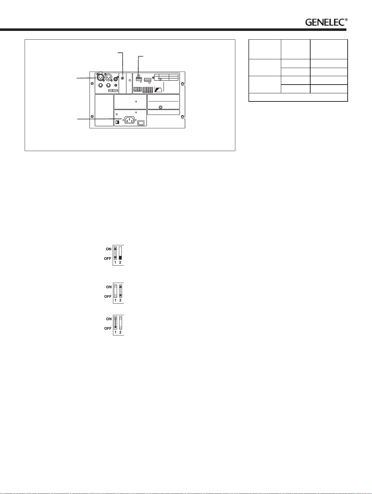
Remote
control type
Pole or
contact
Connect to
remote control
input pin no.
+112 V DC
remote
control
-2
Contact 1 3External
switch or
relay
Contact 2 4
Connect only one remote control unit at a time
SENSITIVITY
ADJUSTMENT
XLR INPUT,
LINK OUT AND
RCA INPUT
CONNECTORS
MAINS VOLTAGE
SELECTOR,
CONNECTOR
XLRINPUT
123
DONOT USE BOTH INPUTS
ATTHE SAME TIME
WARNING
ELECTRICSHOCK HAZARD!
ITIS FORBIDDEN TO UNDOANY
SCREWSON THIS EQUIPMENT.
SERVICINGANDADJUSTMENT
MUSTONLYBE CARRIED OUT BY
QUALIFIEDSERVICE PERSONNEL
NEVEROPERATETHIS EQUIPMENT
WITHOUTAPROPER EARTHED
MAINSCONNECTION.
ENSURETHATTHE CORRECT
VOLTAGEISSELECTED BEFORE
CONNECTINGTO THE MAINS
SUPPLY.
THISEQUIPMENT IS CAPABLEOF
PRODUCINGSOUND PRESSURE
LEVELSIN EXCESS OF 85dB WHICH
MAYCAUSEPERMANENT HEARING
DAMAGE.
DONOT EXPOSE TO WATEROR
MOISTURE.
RCAINPUT
LINKOUT
OUT
IN
231
PIN 123
SIGNAL GND + -
.
+3 0
+6
-3
+9
-6
+12
dBu
SENSITIVITYFOR
1
100dBSPL@1m
2
ROOM CONTROL SETTINGS
REFERTO THE OPERATING MANUAL FOR SUGGESTED
CONTROLSETTINGS.
FORA FLATFREE FIELD RESPONSE
SETALL TONE CONTROLS TOOFF.
CALPOSITION
ALLCONTROLS : OFF
INPUTSENSITIVITY : -6dBu
MAINS
VOLTAGE
SELECTOR
AND SWITCH
Figure 1. Connectors and controls of the HTS3B.
PHASE, BASS ROLL-OFF,
AUTOSTART AND REMOTE
CONTROL SWITCHES
ROLL-OFF
POWER
GREEN =
NORMAL
OPERATION
YELLOW=
STANDBY
MAINSINPUT
50/60Hz
200Watts
115/230V~
PHASE
0/-90DEG
0/-180DEG
AUTOSTART
REMOTECONTROL
PHASEATCROSSOVER
PHASE
0°
-90°
-180°
-270°
-2dB
-4dB
-6dB
SW2
SW1
OFF
OFF
ON
OFF
OFF
ON
ON
ON
ON
CONNECTOR
REMOTE
PINNO.
CONTROL
1+
INPUTS
2 GND
ON
3EXTERNALSWITCH
4ORRELAY
OFF
+ GND
1234
BASSROLL-OFF
dB
ALLOFF
SW5
SW4
ROLL-OFF
SW3
0
0dB
OFF
OFF
OFF
-2
-2dB
-4
OFF
OFF
ON
-6
-4dB
ON
OFF
OFF
-8
-6dB
OFF
OFF
ON
-10
-8dB
OFF
ON
ON
-10dB
ON
ON
ON
18Hz 120Hz
GENELECR
HTS3BACTIVE HOME THEATER SUBWOOFER
MAGNETICALLYSHIELDED
SERIAL
NUMBER
REMOTECONTROLTYPE
12VDC REMOTE
DONOT USE BOTH REMOTE CONTROL
TYPESATTHE SAME TIME.
SWITCHTHE REMOTE CONTROLDIP
SWITCHON WHEN USING REMOTE
CONTROL.
REMOTECONTROLOVERRIDES
AUTOSTARTFUNCTION.
AUTOSTARTSETSTHE AMPLIFIER TO
STANDBYMODEWHEN THERE IS NO
SIGNAL.
AMPLIFIERMODE
PIN1HIGH: ON
PIN1LOW: STANDBY
CONTACTCLOSED:ON
CONTACTOPEN:STANDBY
www.genelec.com
MADEIN FINLAND
Table 1. Remote control connectors of the
HTS3B and HTS4B
variable or fi xed, consult the operating
manual of your processor.
• Connect an audio frequency signal
generator to one of the input channels
used in the system.
• Set the frequency generator to the same
frequency as the subwoofer crossover
frequency on your decoder. If a signal
generator is not available, you can use an
audio test recording with a suitable range
of test frequencies.
• Toggle the -180° phase switch
‘ON’ and ‘OFF’ and set it to the
position which gives the lowest
sound level at the listening
position.
• Next toggle the -90°phase
switch ‘ON’ and ‘OFF’, and
again set it to the position
which gives the lowest sound
level.
• Finally, set the -180°phase
switch to the opposite setting.
After the phase setting has been completed,
return the speaker confi guration on the processor to its’ original settings.
Using multiple subwoofers
The HTS3B and HTS4B are equipped with
a “LINK OUT” connector to provide an easy
way of coupling two or more subwoofers
together in high SPL applications. Connect
an XLR cable from the “LINK OUT” connector of the “master” subwoofer to which the
decoder is connected, to the XLR input connector of the other, “slave” subwoofer.
When two subwoofers connected in this
way are positioned close to one another,
bass level increases by 6 dB . Three subwoof-
ers give an bass SPL increase of 9,5 dB and
four subwoofers 12 dB compared to a single
subwoofer. Adjust the sensitivity control of all
subwoofers in the group to match the SPL
level of the main monitor system. Note that
the sensitivity setting must be the same on
all subwoofers.
Autostart and remote control
H
TS3B and HTS4B are equipped with an
“AUTOSTART” function, which automatically
turns the amplifi er to “STANDBY” mode if
an input signal has not been detected for
approximately 30 minutes, and back to
“ON” mode when the signal returns. The
function can be deactivated by turning the
“AUTOSTART” dip switch to “OFF”. A twocolour LED on the amplifi er panel indicates
the amplifi er status: green for “ON” and
yellow for “STANDBY”.
The amplifi er mode can also be switched
by a remote control unit connected to the
respective inputs on the amplifi er. Two pairs
of connectors are provided, 1 and 2 for a
12 V DC trigger type remote control, and 3
and 4 for an external switch or relay type
control. Switch the “REMOTE CONTROL”
dip switch to “ON” to activate this function.
Do not connect two remote controls to the
subwoofer at the same time. Remote control
overrides the “AUTOSTART” function.
Automatic protection circuits
Both HTS3B and HTS4B subwoofers have
protection circuits against speaker driver
thermal overload and amplifi er overheating.
The protection system resets automatically
so that the user only has to turn the input
level down to ensure that it does not reactivate.
Safety considerations
Genelec HTS3B and HTS4B comply with international safety standards. However, to ensure
safe operation and maintain the equipment in
safe operating condition the following warnings and cautions must be observed.
• Servicing and adjustment must only be
performed by qualifi ed service personnel.
• Opening the amplifi er panel is strictly
prohibited except by qualifi ed service
personnel.
• Do not expose the subwoofer to water or
moisture. Do not place any objects fi lled
with liquid, such as vases on the
subwoofer or near it.
• Always use a mains power connection
with protective earth. Failing to do this
may lead to personal injury.
• Note that the amplifi er is not completely
disconnected from the AC mains service
unless the mains cable is removed from
the amplifi er or the mains outlet.
Warning!
This equipment is capable of delivering sound
pressure levels in excess of 85 dB, which may
cause permanent hearing damage.
Maintenance
There are no user serviceable parts inside
the subwoofer. Any maintenance of the unit
must only be performed by qualifi ed service
personnel.
Guarantee
This product is supplied with two year guarantee against manufacturing faults or defects that
might alter the performance of the unit. Refer to
supplier for full sales and guarantee terms.
Page 4
HTS3B and HTS4B Operating Manual
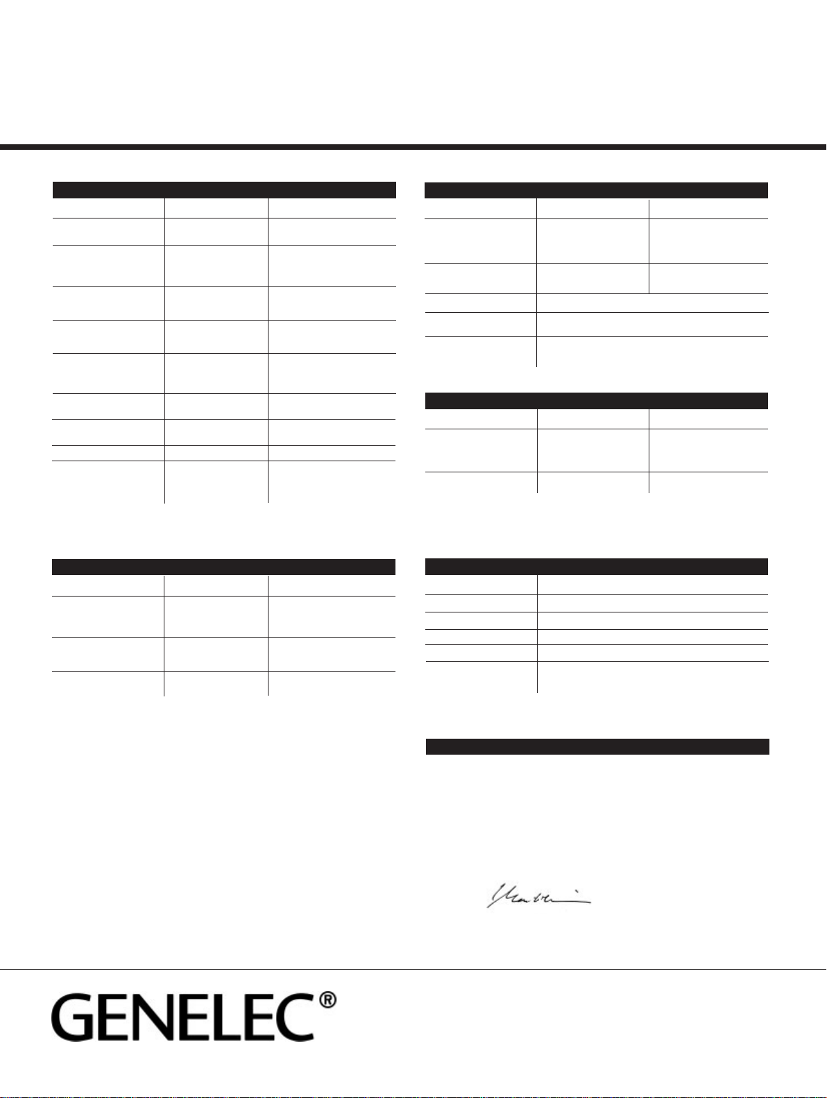
SYSTEM SPECIFICATIONS
HTS3B HTS4B
Free fi eld frequency response 18 Hz…120 Hz 18 Hz…120 Hz
(+/- 3 dB)
Maximum short term sine wave
SPL output averaged from
30 to 85 Hz, measured in
half space at 1 meter ≥ 108 dB SPL ≥ 112 dB SPL
Maximum peak SPL output with
random pink noise, measured
in half space at 1 meter ≥ 113 dB SPL ≥ 117 dB SPL
Self generated noise level in
free fi eld @ 1 m on axis
(A-weighted) ≤ 15 dB ≤ 15 dB
Harmonic distortion @ 95 dB SPL @ 95 dB SPL
at @ 1 m on axis in half space 30 … 120 Hz 30 … 120 Hz
2nd ≤ 2 % ≤ 2 %
3rd ≤ 2 % ≤ 2 %
Driver, magnetically shielded 250 mm (10”) 305 mm (12”)
Passive radiators 2 x 250 mm (10”) 2 x 305 mm (12”)
Maximum permissble 35° C (95°F) 35° C (95°F)
ambient temparature
Weight 28 kg (62 lbs) 37 kg (81 lbs)
Dimensions
Height 433 mm (17 1/16”) 518 mm (20 3/8”)
Width (including grilles) 398 mm (15 5/8”) 483 mm (19”)
Depth 400 mm (15 3/4”) 465 mm (18 5/16”)
If the subwoofer is fl ush mounted into a wall or a cabinet, the recess must be 10 cm (4”)
wider and 10 cm (4”) higher and deeper than the subwoofer itself to allow suffi cient clearance
for the passive radiators and air circulation for cooling.
AMPLIFIER SECTION
HTS3B HTS4B
Short term amplifi er output
power (Long term output power
is limited by driver unit
protection circuitry) 200 W 400 W
Amplifi er system distortion
at nominal output
THD ≤ 0.05% ≤ 0.05%
Mains voltage 100/200 V 100/200 V
or 115/230 V or 115/230 V
INPUT SECTION
HTS3B HTS4B
Input connector XLR female 1, balanced 1, balanced
pin 1 gnd gnd
pin 2 + +
pin 3 - -
Input connector RCA female 1, unbalanced 1, unbalanced
sleeve gnd gnd
pin + +
Input impedance 10 kOhm balanced (XLR), unbalanced (RCA)
Input level for 100 dB SPL
output @ 1 m Variable from +12 to –6 dBu
Remote control inputs External 12 V DC / Relay or switch
OUTPUT SECTION
HTS3B HTS4B
Link Out connector XLR male
pin 1 gnd gnd
pin 2 + +
pin 3 – -
Link Out gain 0 dB 0 dB
CONTROLS
HTS3B HTS4B
Input sensitivity +12 to –6 dBu
Bass roll-off 0 / -2 dB / -4 dB / -6 dB / -8 dB / -10 dB @ 20 Hz
Phase adjustment 0° / -90° / -180° / -270°
Autostart Signal sensing Standby/On switching
Remote control Activates remote controlled Standby/On switching by 12 V
trigger or external switch
Genelec Document D0060R001. Copyright Genelec Oy 10.2003. All data subject to change without prior notice
This is to certify that the Genelec HTS3B and HTS4B Home Theater Subwoofers conform to the
following product specifi cations:
Safety: EN 60065
EMC: EN 55013, EN 55020,
EN 61000-3-2 and EN 61000 3-3
The products herewith comply with the requirements of The Low Voltage Directive73/23/EEC and
EMC Directive 89/336/EEC as amended by Directive 93/68/EEC
Signed:
Ilpo Martikainen
Position: Managing Director
Date: 20-Sep-2003
International enquiries:
Genelec, Olvitie 5
FIN-74100, Iisalmi, Finland
Phone +358 17 83881
Fax +358 17 812 267
Email genelec@genelec.com
EC DECLARATION OF CONFORMITY
In the U.S. please contact:
Genelec, Inc., 7 Tech Circle
Natick, MA 01760, U.S.A.
Phone +1 508 652 0900
Fax +1 508 652 0909
Email genelec.usa@genelec.com
In China please contact:
Genelec China Representative Office
Soho New Town, 88 Jianguo Road
D-1504, Chaoyang District
Beijing 100022, CHINA
Phone +86 10 8580 2180
Fax +86 10 8580 2181
www.genelec.com
 Loading...