

Page 1
HT324A
Operating Manual
Genelec HT324A
Three-Way Active Loudspeaker
Page 2

System
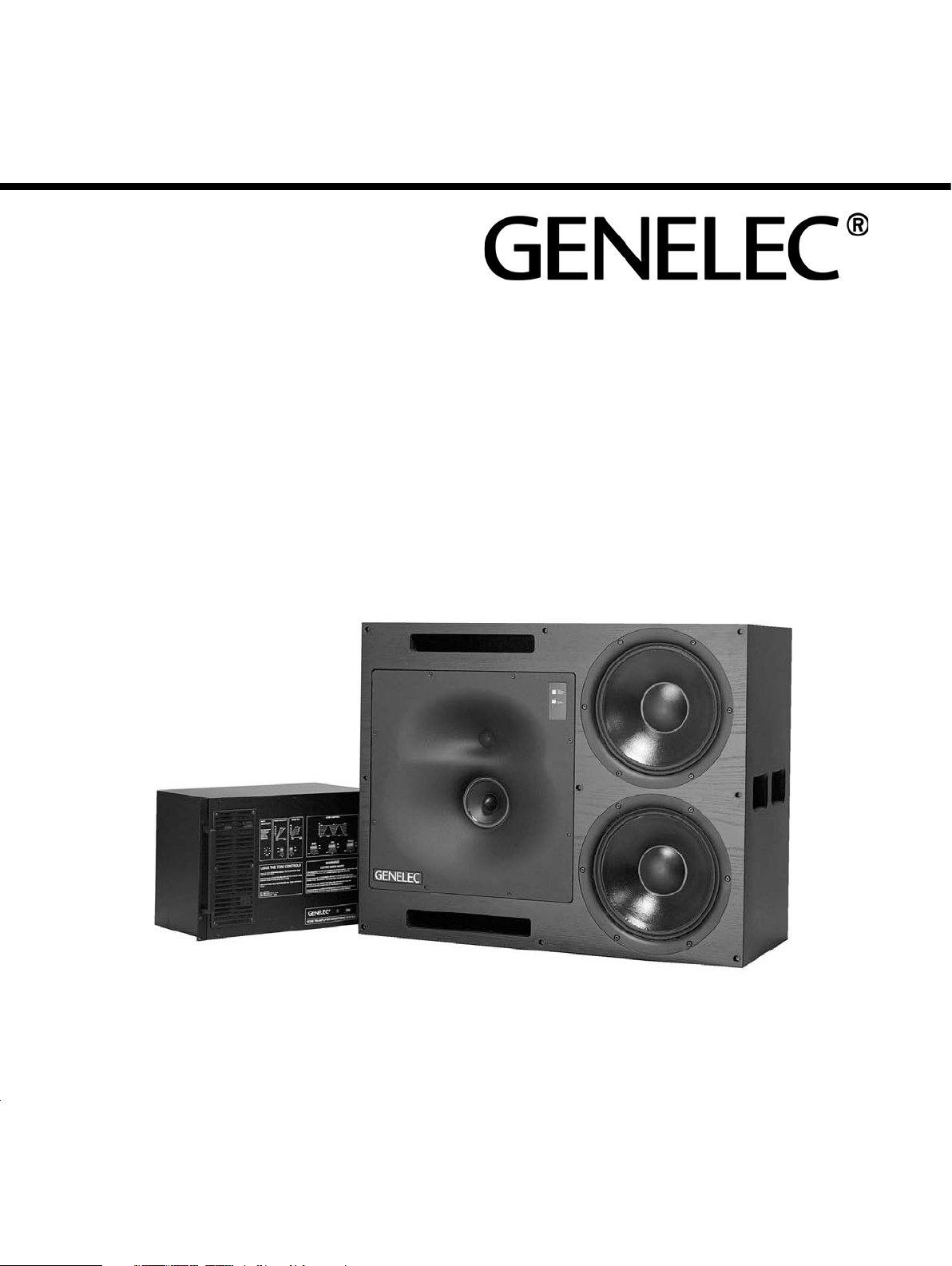
The GENELEC HT324A active loudspeaker
is designed for neutral sound reproduction at
high SPLs in large Home Theater rooms. The
system consists of a 160 litre loudspeaker cab-
inet and a 19” 7U rack mount amplifier unit.
The cabinet contains two 305 mm (12”)
bass drivers, a 130 mm (5”) midrange, and
a 25 mm (1”) treble driver. The midrange
and treble drivers are mounted in a Genelec
Directivity Control Waveguide™ (DCW™)
which can be rotated through ±90° for either
horizontal or vertical mounting. The cabinet
low frequency -3 dB point is at 32 Hz and the
bass response extends down to 27 Hz. The
high frequency response extends up to 22 kHz
(-3 dB).
Each amplifier unit contains a three-chan-
nel active crossover, driver overload protec-
tion circuits, and four separate power ampli-
fiers producing 2 x 400 W, 350 W and 120 W
of shor t term power in the bass, midrange,
and treble channels respectively. The crosso-
ver filter incorporates tone controls to enable
the user to accurately match the speaker to
the local acoustic environment.
number. Make sure that each amplifier is con-
nected to the cabinet bear ing the same ID
number when installing multiple loudspeakers.
Make sure that the amplifier is positioned
so that the loudspeaker connecting cables will
reach. Longer cable lengths can be ordered
from the manufacturer upon special request.
A space 120 mm deep should be left behind
the rear panel of the amplifier unit to allow for
the cable connectors.
Check that the amplifier unit is wired to the
correct mains voltage for your power supply.
The correct mains voltage for the amplifier
unit is shown at the bottom of the sticker on
the rear panel of the amplifier unit.
The amp lifier m ode can b e swi tched
between ON and standby modes by a remote
con trol unit connected to the respective
inputs on the amplifier. Two pairs of connec-
tors are provided, 1 and 2 for a 12 V DC type
remote control, and 3 and 4 for an external
switch or relay type control. Do not connect
two remote controls to the loudspeakerat the
same time. Activate the function by turning
the "REMOTE CONTROL" dip switch on the
amplifier panel to "ON".
acoustical reasons. Flush mounting improves
the bass response and efficiency and also
enhances the midrange transient and fre-
quency response.
The loudspeaker has its acoustical axis
midway between the midrange and treble
drivers. This axis should be used as the lis-
tening and measuring axis of the system.
(See Fig 2.1 and Fig 2.2)
The listening position should be between
2 ... 3.5 m (6½ ... 11½’) from the loudspeak-
ers. The loudspeaker should be aimed so
that the acoustical axis of the two loudspeak-
ers meet at ear height at the center of the
listening area. The loudspeakers should not
be mounted too high as this increases the
required vertical tilt of the loudspeaker and
reduces the optimum listening area.
The ceiling, side walls and especially the
rear wall should be acoustically absorbent at
low frequencies. The loudspeaker mounting
wall should be acoustically hard and there-
fore reflective. The mounting wall should be
angled so that the loudspeakers are correctly
aimed. Great care should be taken over how
the loudspeaker is mounted into the wall.
Unpacking
The Genelec HT324A can be transported as
a pair or as a single system. A pair is shipped
in a single box, containing two cabinets, two
amplifier units, two mains connecting cables,
two LED connecting cables, two loudspeaker
connecting cables and one Allen key. (See
Fig 1)
Before installing the system, check all
items for damage and omissions. If there are
any damaged products, contact directly the
distributor and insurance agent. If there are
any missing components, contact your local
dealer or Genelec.
Installing the amplifier
The Genelec HT324A amplifier electronics is
encased in a standard 19” 7U rack chassis.
The unit should be well ventilated to prevent
overheating, there must be a supply of air to
the front and sufficient ventilation to dissipate
the generated heat from the space behind
the amplifier unit. The maximum permissible
ambient temperature is 35° C (95° F) If the
system overheats it will stop operating until a
safe temperature is reached.
Each amplifier unit has been calibrated
at the factory with the loudspeaker cabinet it
is packed with. They also share the same ID
Loudspeaker positioning
The HT324A is designed to be flush mounted
in either the vertical or horizontal configura-
tion. The DCW™ should be rotated so that
the treble and midrange drivers align verti-
cally. This ensures that optimum symmetry is
obtained.
Note that the DCW™ plate is heavy, care
must therefore be taken when removing and
replacing the DCW™. To rotate the DCW™
plate, proceed as follows:
• Place the loudspeaker in its intended
listening orientation.
• Unscrew the eight M5 fixing screws on
the edges of the plate using the 4 mm
Allen key provided with the system.
• Carefully pull the plate a small distance
away from the cabinet.
• Rotate the DCW™ so that the midrange
and treble drivers are aligned vertically
(treble driver on top) and remount the
DCW™ plate reversing the procedure
above.
Flush mounting of the
loudspeaker
Although the HT324A may be used suc-
cessfully as a free standing loudspeaker,
flush mounting is strongly recommended for
Note the following:
• A space 50…100mm (2..4”) wide can be
left around the loudspeaker.
• Cover the space around the
loudspeaker with a facing panel, this
should be fixed to the wall. Leave a gap
of about 5..10 mm (¼..½”) between the
loudspeaker and the panel. Fill this gap
with a soft rubber gasket to allow for
possible cabinet movement.
• Ensure that the loudspeaker cables can
reach the rear of the loudspeakers.
• If a light (e.g. wooden) wall is used,
the loudspeaker cabinet should be
mounted on vibration isolators, with a
resonant frequency of around 2…8 Hz,
to prevent vibrations from being
transmitted to the wall and impairing
the low frequency performance. The
space around the cabinet should be
filled with absorbent mineral wool or
foam plastic. The walls must be well
braced.
• For a solid wall (e.g. concrete), the
loudspeaker may be directly mounted to
the wall without vibration isolators. The
space around the cabinet should be
filled with mineral wool or sand bags.
Page 3

Discontinuities in the mounting wall will cause
diffraction, which leads to inferior frequency
response and stereo imagery, so:
• Ensure that the cabinet is flush with the
surface of the wall.
• If a decorative cloth frame is used to
cover the wall, make sure that the edges
adjacent to the speaker are less than
20 mm (3/4”) deep. The cloth must be
very thin Tricot or acoustically
transparent material, otherwise the high
frequency response of the system will
be adversely affected. Genelec
approved cloth grilles are available).
Recess for loudspeaker
connectors
A space at least 120 mm (4 3/4”) deep
must exist to allow for the cable connectors
behind the loudspeaker. The dimensions of
the recess should be at least 100 x 140 x 75
mm (4” x 51/2” x 3”), as shown in Fig. 6. Note
that the connectors are positioned off-center.
Therefore, if the loudspeaker is rotated for a
left and right channel, the recess will be at dif-
ferent heights on the left and right side. This
occurs when the loudspeakers are mounted
in the horizontal configuration.
Connecting cable
The two connecting cables have different
types of connectors at each end, a loud-
speaker connector and an LED connector.
The loudspeaker connector is larger than the
LED connector. Insert the connectors into the
appropriate sockets found on the rear panel
of the amplifier unit and the rear of the loud-
speaker.
To insert the connectors proceed as follows:
• Insert the connectors into the sockets
and turn the connectors clockwise. The
connectors lock automatically.
• The electrical connections are only
made when the connectors are fully
inserted.
To remove the connectors pull the release
lever on the connector and turn the connec-
tor counterclockwise simultaneously. The
connector can now be removed from the
socket.
Acoustical Setup
Input sensitivity adjustment
The input sensitivity of the HT324A can be
adjusted to match the output signal level of
the signal source. This is done by turning the
Speaker mounting
envir onment
Flat anechoic
response (factor y
setting)
Free s tanding in
a heavily damped
room
Free s tanding in a
reverberant room
Flush mounted in a
hard wall
In a corner -4 dB ON -6 dB ON -2 dB ON All OFF All OFF
Table 1.Suggested starting positi ons for tone controls.
Bass Roll-Off Bass Tilt Bass Level Mid Level Treble Level
All OFF All OFF All OFF All OFF All OFF
All OFF -2 dB ON All OFF All OFF All OFF
All OFF -2 dB ON -1 dB ON All OFF All OFF
All OFF -4 dB ON -1 dB ON All OFF All OFF
‘Input sensitivity’ trimmer, which is accessed
through the front panel of the amplifier unit.
However, an accurate left/right balance is
obtained when the trimmer is set to the fully
clockwise ‘cal’ position. Leaving the input sen-
sitivity trimmer in the ‘cal’ position is therefore
recommended.
To obtain the maximum sound pressure
level of 123 dB SPL, with the input sensitiv-
Control
Measuring the frequency response
The overall sound balance expe rienced
at the listening position can, to a certain
extent, be measured with steady state sig-
nals (e.g. pink noise, warble sine etc.) and
a corresponding frequency analyser. How-
ever, the results obtained are very sensitive
to the measuring methods and the equip-
ment used.
ity set to -6 dBu, a signal level of +20 dBu is
required.
Recommended Measuring Equipment
1. Microphone
Tone control adjustment
The frequen cy response o f t he system
should be adjusted to match the listening
room’s acoustic environment. This adjust-
ment is made using the tone controls, ‘BASS
TILT’, ‘BASS ROLL-OFF’, ‘BASS LEVEL’,
‘MIDRANGE LEVEL’, and ‘TREBLE LEVEL’.
These controls are accessed through the
amplifier unit’s front panel. The default set-
ting of these controls is in the ‘OFF’ position,
• Always use a laboratory grade
measurement microphone.
• B&K 4134 (or similar) for far field, 4133
or 4165 (or similar) for near field below
8kHz.
• B&K 4004 and 4007 (or similar) up to
8kHz.
Do not use a microphone having a polar pattern
other than omnidirectional, or one not having
an accurately known frequency response.
which yields a flat frequency response when
the speaker is operated in an anechoic envi-
ronment. Note that only one switch in each
control group should be in the ‘ON’ position.
The room normally boosts the low frequen-
cies compared with free field conditions. To
get a flat room response, adjustments to
the bass tone control switches are usually
required. See table 1 for suggested starting
2. Signal Source
Use a signal source which is suitable for the
type of analyser being used. Do not use a
noise generator which is integrated into a
mixing console, since these signal genera-
tors tend to have a very coarse spectrum
content and are not intended to be used for
measurement purposes.
positions of the tone controls in four differ-
ent room types. The table shows that the
midrange and treble controls should be left in
their free field positions, since these frequen-
cies are controlled by the speaker more than
the room. Acoustical measurements, and
3. Analyser
Any professional quality real time analyser
or tracking plotter can be used. (1/3 or 1/1
octave analysis is usually sufficient for fre-
quency response balancing)
precise listening tests should be completed
by qualified personnel, to determine the opti-
mum tuning in each case.
Near field measurement
This measurement gives an indication of the
Page 4

Loudspeaker
cabinet
Amplifier
unit
Mains
connecting
cable
Loudspeaker
connector
LED connector
Allen key
Fig 2.1 Hor izontal configuration.
Fig 1. The HT324A s ystem.
Fig 3. Speaker mou nting.
Fig 4. Speaker mou nting details.
Fig 2.2 Vertical configuration.
Fig 5. Eliminating discontinuiti es.
Fig 6. Recess for loudspeaker connect ors.
(Front view)
Fig 7. Amplifier unit connec tors.
Fig 8. Speaker/LED connector
Page 5

direct sound radiation of the loudspeaker
below 1 kHz.
• Set the microphone 1 m away from the
loudspeaker on the acoustic axis. (See
Fig 2.1 and 2.2)
• Measure the frequency response of
the speaker, and adjust the tone controls
to achieve a flat frequency response
below 1kHz.
Make sure that any sound reflecting objects
such as chairs etc. are removed from the
close proximity of the loudspeaker.
Listening position measurement
Once the near field frequency respon se
measurement has been made, the frequency
response at the listening position can be
determined by the same means. When com-
paring the results, the following items should
be noted.
1. High frequency roll-off
This is due to the following physical factors:
• Increasing room and air absorption with
higher frequencies.
• Increasing loudspeaker and microphone
directivity with increasing frequency.
2. Low frequency irregularities.
These are caused by:
• Insufficient standing wave absorption in
the control room.
• Reflections from nearby boundaries
(Floor, ceiling, walls) interfering with
direct sound.
Incorrect vertical speaker alignment can
cause interference dips at the upper crosso-
ver frequency (around 3.2 kHz). Hence care
should be taken aiming the speaker correctly
towards the listening position. (See Fig 3.)
Overload indicators
Each loudspeaker is provided with two LED’s
marked ‘CLIP PROTECT (FAULT)’ and
‘READY’. The green ‘READY’ LED indicates
that the amplifier system power is switched
on, and that the speaker is ready for use.
The red ‘CLIP PROTECT (FAULT)’ LED
indicates that the amplifier system is over-
loaded or that the driver protection circuit is
activated. If the red LED lights, reduce the
signal level so that the LED stops blinking.
If this LED stays lit constantly, the amplifier
thermal protection circuitry has activated.
Let the amplifier cool down, and ensure that
the amplifier is adequately ventilated.
Maintenance
There are no user serviceable par ts within
the amplifier unit. Any maintenance of the
unit should only be undertaken by qualified
service personnel. Ensure that only fuses
of the appropriate voltage and current rat-
ings are used if a fuse has to be replaced.
REMEMBER to disconnect the power supply
by removal of the mains cable before chang-
ing a fuse. Clean the amplifier unit’s air filter
every six months, or more frequently in dusty
environments. The air filter is located behind
the grille, found to the left of the front panel.
The air filter can be cleaned with a vacuum
cleaner without removing the grille.
Safety considerations
Although the HT324A has been designed in
accordance with international safety stand-
ards, to ensure safe operation and to main-
tain the instrument under safe operating con-
ditions, the following warnings and cautions
should be observed:
• Servicing and adjustment must only
be performed by qualified service
personnel. The loudspeaker or the
amplifier must not be opened.
• The amplifier must only be connected
to mains socket outlet with a protective
earthing connection.
• Do not use the amplifier with
an unearthed mains cable as this may
compromise electrical safety.
• Do not expose the loudspeaker or the
amplifier to water or moisture. Do not
place any objects filled with liquid, such
as vases, on the loudspeaker or near it.
• Do not place naked flame sources like
lighted candles on or near the
loudspeaker or the amplifier.
• This loudspeaker is capable of
producing sound pressure levels
in excess of 85 dB, which may cause
permanent hearing damage.
• Proper ventilation of the amplifier is
necessary to maintain sufficient cooling.
Ensure that air flows freely into the
openings on the amplifier front panel
and that the space behind the amplifier
is sufficiently ventilated to dissipate the
generated heat.
• Note that the amplifier is not completely
disconnected from the AC mains service
unless the mains power cord is removed
from the amplifier or the mains outlet.
Guarantee
This product is guaranteed for a period of one
year against faults in materials or workman-
ship. Refer to supplier for full sales and guar-
antee terms.
EC Declaration of Conformity
This is to certify that Genelec HT324A loud-
speaker conforms to the following standards:
Safety:
EN 60065 / IEC 60065:1998 7th Edition
EMC:
EN 55013: (2001)
EN 55020: (1994), A11: (1996), A12: (1999),
A13: (1999), A14: (1999)
EN 61000-3-2 (2000)
EN 61000-3-3 (1995)
The product herewith complies with the
requirements of The Low Voltage Directive
73/23/EEC, EMC Directive 89/336/EEC and
93/68/EEC
Signed:
Ilpo Martikainen
Position: Chairman of Board
Date: 16-January-2006
Page 6

HT324A Operating Manual
Figure 9: The above cur ves illustrate the effect of the 'bass tilt', 'bass rolloff' and 'bass',' mid' and 'treble' level controls on the free field response,
measured at 2 m
SYSTEM SPECIFICATIONS
Lower cut-off frequency, -3 dB: <32 Hz
Upper cut-off frequency, -3 dB:
Free field frequency response of system:
33 Hz - 20 kHz (± 2.5 dB)
Maximum short term sine wave acoustic output on
axis in half space, averaged from 100 Hz to 3 kHz
@ 1 m
Maximum long term RMS acoustic output in same
conditions with IEC-weighted noise (limited by driver
unit protection circuit)@ 1 m:
≥118 dB SPL
Maximum peak acoustic output per pair @ 2 m from
the engineer with music material:
>125 dB
Self generated noise level in free field @ 2 m on
axis:
Harmonic distortion at 100 dB SPL @ 1m on axis:
Freq: 50...200 Hz <1%
200...10kHz <0.5%
Drivers:
Bass 2 x 305 mm (15") cone
Mid 1 x 130 mm (5") cone
Treble 1 x 25 mm (1") metal dome
Weight: Speaker 73 kg (161 lb)
Amplifier 30 kg (66 lb)
Speaker dimensions (Horizontal mounting):
Height 700 mm (27
Width 890 mm (35")
>20 kHz
>123 dB SPL
≤15 dB(A)
9
/16")
CROSSOVER SECTION
Bass amplifier output power with an 8 Ohm load:
Short term 2 x 400 W
Mid amplifier output power with a 8 Ohm load:
Short term 350 W
Treble amplifier output power with an 8 Ohm load:
Short term 120 W
Long term output power is limited by driver unit
protection circuitry.
Slew rate: 80 V/µs
Amplifier system distortion at nominal output:
THD
SMPTE-IM
CCIF-IM
DIM 100
Signal to Noise ratio, referred to full output:
Bass
Mid
Treble
Mains voltage: 100/200 or 115/230V
Voltage operating range at
230V setting: 207 - 244 V (-10/+6 %)
115V setting: 104 - 122 V (-10/+6 %)
Power consumption:
Idle 70 W
Full output 1000 W
Depth 383 mm (15")*
Amplifier dimensions:
Height 310 mm (12
Width 483 mm (19")
Depth 250 mm (9
13
3
/16")
/16")*
Figure 10: The upper curve group shows th e horizontal directivity
characteristics of the HT324A in its hor izontal configuration measured
at 2m. The lower curve is a 1/6 octave power respon se measurement,
derived from 144 di rectivity measurem ents.
AMPLIFIER SECTION
Input connector: XLR female pin 1 gnd
pin 2 +
pin 3 -
<0.05%
<0.05%
<0.05%
<0.05%
<100 dB
<100 dB
<100 dB
Input impedance: 10 kOhm balanced
Input level for 100 dB SPL output @ 1m:
variable from +6 to -6 dBu
Input level for maximum short term output of 126 dB
SPL @ 1m: variable from +32 to +20 dBu
Subsonic filter below 25 Hz : 18 dB/octave
Ultrasonic filter above 22 kHz: 12 dB/octave
Crossover frequencies:
Bass/Mid 400 Hz
Mid/Treble 3.2 kHz
Crossover acoustical slopes: >24 dB/octave
Level control operating range in 1 dB steps:
Bass from 0 to -6 dB & MUTE
Mid from 0 to -6 dB & MUTE
Treble from 0 to -6 dB & MUTE
Bass roll-off control in 2 dB steps:
from 0 to -8 dB @ 32 Hz
Bass tilt control operating range in 2 dB steps:
from 0 to -8 dB @ 50 Hz
The 'CAL' position is with all tone controls set to 'off'
and input sensitivity control to maximum and corresponds to a maximally flat free field response.
Genelec Docu ment D0072R001 Copyrig ht Genelec Oy 1.2006. All data subject to change without prior notic e
Inter national e nquiries:
Genele c, Olvitie 5
FIN-74 100, Iisal mi, Finlan d
Phone +358 17 83 881
Fax +358 17 812 267
Email genele c@genelec.com
In the U.S. please c ontact:
Genele c, Inc., 7 Tech C ircle
Natick, MA 01760 , USA
Phone +1 508 652 0900
Fax +1 508 652 0 909
Email genele c.usa@genelec.com
In Chi na please contact:
Genele c China Re presentati ve Office
Soho N ew Town, 88 Jiangu o Road
D-1504 , Chaoyang D istrict
Beijin g 100022, China
Phone +86 10 858 0 2180 Fax +86 10 85 80 2181
Email genelec.china@genelec.com
www.genelec.com
In Sweden ple ase contact
Genelec Sveri ge
Ellipsvägen 10 B
P.O. Box 5521, S- 141 05 Huddinge
Phone +46 8 449 5220
Fax +46 8 708 70 71
Email info@gen elec.com
 Loading...