

Page 1
HT320AC
Operating Manual
Genelec HT320AC
Active Home Theater System
Page 2
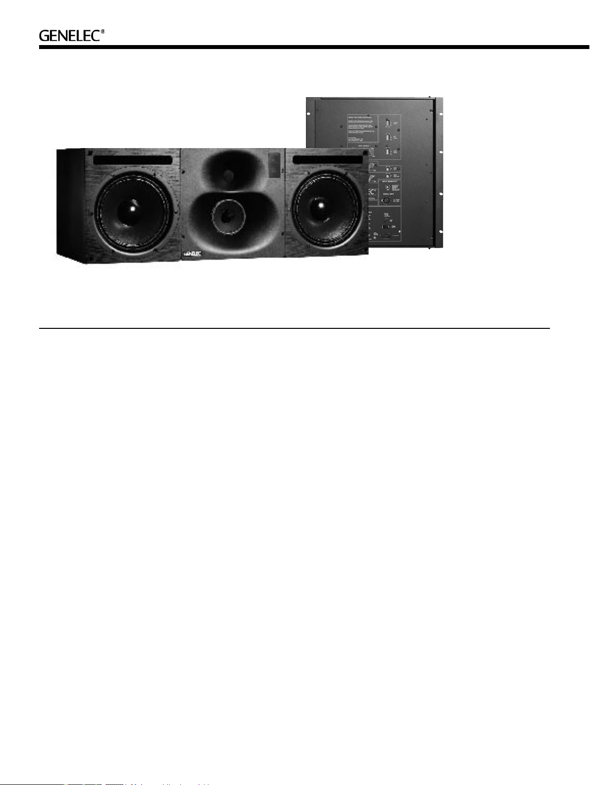
Genelec HT320AC Active Home Theater System
System
The Genelec HT320AC is a dedicated
center channel loudspeaker for three
channel (LCR) and Surround systems. Its
compact cabinet has been designed for
optimum placement in the limited space
above or below a video monitor or screen.
The HT320AC is a three-way active loud-
speaker including drivers, multiple power
amplifiers and active cross overs. The
amplifiers and crossovers are built into a
separate rack mount chassis.
The system is designed for room vol-
umes up to 250 m3 / 8800 ft3 with maximum
listening distances up to 6.1 - 7.6 meters
(20-25 ft) The HT320AC is recommended
to be flush mounted into the wall structure,
but it can also be used as a free-standing
loudspeaker.
The unique Directivity Control Wavegui-
deTM (D C WTM) Tec hno l ogy p rov ides
excellent stereo imaging and frequency
balance even in difficult acoustics envi-
ronments. The fast, low distortion amplifiers
are capable of driving the system to peak
output levels in excess of 124 dB SPL at 2
m with program signals. Versatile crossover
controls allow for precise matching of the
system to different acoustic conditions.
Drivers
The bass frequencies are reproduced by
two 250 mm (10") bass drivers loaded with
a 110 liter vented box. The -3dB point is
33 Hz and the low frequency response
extends down to 29 Hz (-6 dB). The mid-
range frequencies are reproduced by a pro-
prietary 130 mm (5") direct radiating cone
driver loaded with a DCWTM. The high fre-
quency driver is a 25 mm (1") metal dome
also loaded by a DCWTM. The HT320AC is
magnetically shielded in order to minimise
interference with video monitors
Crossover filters
The crossover frequencies of the active
crossover network are 410 Hz and 3.0 kHz.
Special calibrated controls are included in
the crossover in order to obtain a uniform
frequency balance under different acoustic
conditions. ; the Bass, Midrange and Treble
Level controls operate in 1 dB steps. Fur-
thermore, the low frequency Tilt and Roll-
Off controls both have four 2 dB steps to
allow refined LF response tailoring
A high-pass filter is included in the LF
channel to protect the woofer from sub-
sonic signals. The crossover network is
driven by an active balanced input stage
.
fed by a 3 pin XLR. Variable input sen-
sitivity allows for accurate to the signal
source output.
Amplifiers
The bass, midrange and treble ampli-
fiers produce 400 W, 120 W and 120 W,
respectively of short term power with very
low THD and IM distortion values. The
negative output impedance of the woofer
amplifiers improves acoustic transients.
The system incorporates special circuitry
for driver overload protection and amplifier
thermal protection.
Installation
Each HT320AC loudspeaker is supplied
with a separate amplifier unit in a 19" 12 U
rack mount chassis, a 10 meter connecting
cable set, a mains cable and an operating
manual. Once unpacked, place the loud-
speaker in its required listening position,
taking note of the line of the acoustic axis
(see figure 1) and install the amplifier
into a standard 19" rack. Sufficient cool-
ing for the amplifier must be ensured. The
minimum clearance for the amplifier is 10
centimeters (4”) to any object. The space
adjacent to the amplifier must either be
ventilated or sufficiently large to dissipate
Page 3

Speaker mounting
G
E
N
E
L
E
C
> 1 m
500 mm
(19 3/4 )″
h2
h2=
GENELEC
> 1 m
950 mm (37 3/8 )″
350 mm
(13 3/4
)″
453 mm
(17 7/8
)″
200 mm
(7 7/8 )″
h1
h1=
position
Free field anechoic
response
In a corner -2 dB -2 dB -2 dB None None
Flush mounted in a
wall structure
Table 1. Suggested t one control settings in some typical situations
Bass
roll-off
None None None None None
None None -4 dB None None
Bass
tilt
Bass
level
Midrange
level
Treble
level
Figure1. Locati on of the acoustic axis
heat so that the ambient temperature does
not rise above 35 degrees Celsius (95°F).
When soffit mounting the units it should
be noted that the cable connectors require
10 cm (4") of free space behind both the
loudspeaker and the amplifier.
Before connecting up, ensure that the
mains switch is off (see figure 2). Check
that the mains voltage selector is correctly
set and that the appropriate fuse is fitted.
The connec ting cables b etween the
amplifier and the loudspeaker cabinet
have Speakon 8- and 4-pole connectors.
Push the 4-pole connector in and turn it
clockwise until the retaining clip clicks. The
8-pole (thicker) type is connected by push-
ing the connector in, turning it clockwise
and tightening the blue locking collar at the
end of the connector.
Audio input to the amplifier is made via a
10k Ohm balanced (XLR) lead, but unbal-
anced leads may be used as long as pin 3
is grounded to pin 1 of the XLR (see figure
3). Once connection has been made, the
loudspeakers are ready to be powered up.
Setting the input sensitivity
Adjustment of the input sensitivity of each
loudspeaker can be made to match that of
the signal source, by use of the input sen-
Figure 2. Ampli fier panel layout of the HT320AC
sitivity control on the amplifier panel (see
figure 2). A small screwdriver is needed for
the adjustment. The manufacturer default
setting for this control is -6 dBu (fully clock-
wise) which gives an SPL of 100 dB @1 m
with -6 dBu input level. Note that to get the
full output level of 120 dB SPL, an input
level of +14 dBu is needed at this setting.
Autostart and remote control
Th e HT3 20AC is equi ppe d wit h an
“Autostart” function, which automatically
turns the amplifier to “standby” mode if
an input signal has not been detected for
approximately thirty minutes, and back to
“on” mode when the signal returns. The
function can be deactivated by turning
the “AUTOSTART” dip switch to “OFF”. A
three-colour LED on the loudspeaker indi-
cates the amplifier status: green for “on”
and yellow for “standby”.
The amplifier mode can also be switched
by a remote control unit connected to the
respective inputs on the amplifier. Two pairs
of connectors are provided, 1 and 2 for a
12 V DC type remote control, and 3 and 4
for an external switch or relay type control.
Do not connect two remote controls to the
loudspeaker at the same time. Activate the
function by turning the "REMOTE CON-
Figure 3. RCA t o XLR cable
TROL" dip switch on the amplifier panel to
"ON". Note that the remote control func-
tion overrides the “autostart” dip switch
function.
Setting the tone controls
The acoustic response of the system may
also have to be adjusted to match the
acoustic environment. The adjustment is
done by setting the five tone control switch
groups 'Bass Tilt', 'Bass Roll-Off', 'Bass
Level', 'Mid Level' and 'Treble Level' on the
amplifier. The manufacturers default set-
tings for these controls are 'All Off' to give
a flat anechoic response. See Table 1 for
suggested tone control settings in differing
acoustic environments. Figure 8 shows
the effect of the controls on the anechoic
response. Always start adjustment by set-
ting all switches to the 'OFF' position. Then
set only one switch to the 'ON' position to
select the response curve required. If more
Page 4

Figure 4: Flush mounting the loudspe aker in
FACING PANEL
FIXED TO THE WALL
(50-100 mm / 2-4")
RUBBER GASKET
(5-10 mm / ¼-½")
SPEAKER
WALL
CONCRETE
STRUCTURE
VIBRATION
ISOLATORS
f ~ 2-8 Hz
MULTI-LAYERED WALL
(WOOD, CONCRETE, BRICKS
)
VIBRATION
ISOLATORS
f ~ 2-8 Hz
CONCRETE WALL
SAND
BAGS
VIBRATION
ISOLATORS
f ~ 2-8 Hz
HEAVY WOODEN WALL
ABSORBING
MATERIAL
a wall constr ucted of wood
Figure 5: Flush mounting the loudspe aker in
a wall constr ucted of concrete
Figure 6: Flush mounting the loudspe aker
in a wall constructed of a combination of
materials.
than one switch is set to 'ON' (within one
switch group) the attenuation value is no
longer accurate.
Vertical / horizontal mounting
Genelec HT320AC can be mounted ver-
tically or horizontally. If the loudspeaker's
orientation is changed, the DCW™ plate
must be rotated so that the treble and mid-
range drivers remain vertically aligned with
the mid driver at the bottom of the DCW™.
Remove the four corner screws of the
DCW™ (use a 4 mm Allen key) and pull
the plate carefully out without stressing the
wires and the gasket. Rotate the plate 90
degrees in the appropriate direction and
remount the screws.
Flush mounting
Th e HT3 2 0AC can be us ed fl ush
mounted into the wall structure, which
offers some acoustical benefits. No cabi-
net edge diffraction will occur, resulting
in an improved response, especially at
midrange frequencies. Low frequency
reflections from the wall behind the loud-
speaker can be avoided, which improves
the low frequency response and efficiency
and allows the loudspeaker to work in
half space conditions. In terms of instal-
lation and orientation, the loudspeaker’s
acoustical axis (See figure 1) should point
directly to the listening position. The loud-
speaker should be vertically aimed so that
the acoustical axis of the loudspeakers
meet around ear height at the reference
listening position. In the horizontal plane
the loudspeakers should be positioned
according to the multichannel (ITU-R
BS.775-1) placement recommendation.
The ceiling, side walls and especially the
rear wall should be acoustically absorbent
Figure 7: Covering the gap betwee n the
wall and the loudspeaker cabinet.
at low frequencies. The wall in which the
loudspeakers are mounted should have a
high acoustical mass to properly implement
half space radiation at low frequencies and
be angled so that the loudspeakers are
correctly aimed. However, the loudspeak-
ers should not be mounted too high as this
increases the required vertical tilt of the
speaker (maximum tilt angle < 20 degrees)
and reduces the optimum listening area.
Great care should be taken over how the
loudspeaker is mounted into the wall. Note
the following:
A space 50 to 100 mm (2 to 4”) wide
can be left around the loudspeaker. Cover
the space around the loudspeaker with a
facing panel that should be fixed to the wall.
Leave a gap of about 5 to 10 mm (¼ to ½”)
between the loudspeaker and the panel. Fill
this gap with a soft rubber gasket to allow
for possible movement (see figure 6).
Ensure that the loudspeaker cables can
reach the rear of the loudspeaker cabi-
nets.
Regardless of the type of front wall con-
struction the loudspeaker cabinet should
be mounted on vibration isolators, with a
resonant frequency of 2 to 8 Hz, to pre-
vent vibrations from being transmitted to
the wall and impairing the low frequency
performance.
If a heavy wooden front wall construc-
tion is used, the space around the cabi-
net should be filled with absorbent min-
eral wool or foam plastic. The wooden
wall structure must be heavily braced to
achieve sufficiently high mass and rigidity
(see figure 4).
Page 5

Figure 8: The curves above show the effect of the ‘bass’, ‘mid ’ and
+80
+85
+90
+80
+85
+90
+80
+85
+90
20
20k
50
100 200 500
1k 2k
5k
10k
BASS TILT
BASS LEVEL
BASS ROLL-OFF
MID LEVEL
TREBLE LEVEL
Hz
dBr
AUDIO PRECISION 1038BCANEC vs 22 OCT 02LEVEL(dBr) FREQ(Hz)
+55
+60
+65
+70
+75
+80
+85
+90
+95
20
20k
50
100 200 500
1k 2k
5k
10k
0°
30°
15°
45°
dBr
Hz
AUDIO PRECISION 1038BCANEC vs 22 OCT 02LEVEL(dBr) FREQ(Hz)
‘treble’ level con trols, and the ‘bass til t’ and ‘bass roll-off ’ controls
on the free field response of the HT320AC, measured at 2 m.
Figure 9: The curves above show the hor izontal directivity
character istics o f the HT320AC in its horizontal configuratio n
measured at 2 m.
In a solid wall (e.g. concrete) structure,
the space around the cabinet should be
filled with either absorbent mineral wool or
sand bags (see figure 5).
The wall can also be constructed of a
combination of materials to achieve high
acoustical structural mass that will disable
low frequency sound propagation and pro-
vide high LF sound isolation (see figure 6).
Acoustic consultants will be able to provide
details and design these structures.
Ensure that the cabinet is flush with the
surface of the wall. Discontinuities in the
loudspeaker mounting wall will cause dif-
fraction, which leads to inferior frequency
response and stereo imaging. So, if a deco-
rative cloth frame is used to cover the wall,
make sure that the edges adjacent to the
speaker are less than 20 mm (3/4”) deep.
The cloth must be very thin Tricot or an
acoustically transparent material other-
wise the high frequency response of the
system will be adversely affected. Genelec
approved cloth grilles are available.
Mode indicator LEDs
The Genelec HT320AC is provided with a
three-colour indicator LED on the DCW™
panel. When the LED is green, it indicates
that the loudspeaker is ready for use.
Standby mode is indicated by yellow colour.
Amplifier clipping is indicated by a blinking
red light and thermal protection mode by
a constant red light. If clipping is indicated
reduce the signal level so that the LED stops
blinking. If the red LED stays on constantly,
switch off the loudspeaker and the audio
source and let the amplifier cool down.
Check that the ventilation around the ampli-
fier is not blocked. There should be a clear-
ance of more than 100 mm (4”) between the
amplifier face panel and any solid surface at
the back. If the red light does not come off,
contact authorised Genelec service.
The LED can be deactivated if you find
it disturbing in a darkened room by turning
both the "POWER LED" and "STANDBY
LED" switches on the amplifier panel to
"OFF".
2. Do not use the loudspeaker with an
unearthed mains cable or unearthed
mains connection as this may lead to
personal injury.
3. This loudspeaker is capable of
producing sound pressure levels in
excess of 85 dB, which may cause
permanent hearing damage.
4. Free flow of air around the amplifier is
necessary to maintain sufficient
cooling. Do not obstruct airflow around
the amplifier.
5. To prevent fire or electric shock, do not
expose the unit to water or moisture.
Do not place any objects filled with
liquid, such as vases on or near the
Maintenance
No user serviceable parts are to be found
within the amplifier unit. Any maintenance
or repair of the unit should only be under-
taken by qualified service personnel.
loudspeaker or the amplifier.
6. Note that the amplifier is not
completely disconnected from the AC
mains service unless the mains cable
is removed from the amplifier or the
mains outlet.
Safety considerations
Although the HT320AC has been designed
in accordance with international safety
standards, to ensure safe operation and to
Order code
Protective grille 1038-409BC
maintain the instrument under safe operat-
ing conditions, the following warnings and
cautions must be observed:
This product is supplied with one year
guarantee against manufacturing faults or
be performed by qualified service
personnel. The amplifier must not be
1. Servicing and adjustment must only
defects that might alter the performance of
the HT320AC unit. Refer to supplier for full
sales and guarantee terms.
opened.
Accessories
Guarantee
Page 6

HT320AC Operating Manual
SYSTEM SPEC IFIC ATIONS
HT320AC
Lower cut-off frequency, -3 dB
Upper cut-off frequency, -3 dB
Free field frequency response
of system
Maximum short term sine wave acoustic
output on axis in half space, averaged from
100 Hz to 3 kHz
Maximum long term RMS acoustic output
in same conditions with IEC-weighted noise
(limited by driver unit protection circuit)
Maximum peak acoustic output per pair above
console with music materia
Self generated noise level in free field @1m
on axis
Harmonic distortion at 95 dB SPL at 1m on
axis:
Drivers
Bass
Midrange
Treble
All drivers are magnetically shielded
Weight
Speaker cabinet
Amplifier
Speaker cabinet dimensions
Height
Width
Depth
Amplifier dimensions
Height
Width
Depth
*Without connecting cable s. Cable connectors require
additional 100 mm (4") of space behind the speaker and the
amplifier
<33 Hz
>20 kHz
35 Hz - 20 kHz (±2.5 dB)
@1m >120 dB SPL
@1m >116 dB SPL
@ 2m >124 dB
<15 dB (A weighted)
freq. 50...100 Hz <1%
freq. >100 Hz <0.5%
2 x 250 mm (10") cone
130 mm (5") cone
25 mm (1") metal dome
60 kg (130 lb)
14 kg (31 lb)
350 mm (13 3/4")
950 mm (37 3/8")
453 mm (17 7/8")*
530 mm (20 7/8") (12 U)
480 mm (8 7/8")
113 mm (4 7/16")*
AMPLIFIER S ECTI ON
HT320AC
Bass amplifier short term output power 2 x 200 W (4 Ohm load)
Midrange amplifier short term output power 120 W (8 Ohm load)
Treble amplifier shor t term output power 120 W (8 Ohm load)
Long term output power is limited by driver unit protection circuitry.
Slew rate 80V/µs
Amplifier system distortion at nominal output
THD
SMPTE-IM
CCIF-IM
DIM 100
<0.05%
<0.05%
<0.05%
<0.05%
Signal to Noise ratio, referred to full output
Bass
Midrange
Treble
>100 dB
>100 dB
>100 dB
Mains voltage 100/200V or 115/230V
Voltage operating range nominal ±10%
Power consumption
Idle
Full output
60 W
500 W
CROSSOVER SECTION
HT320AC
Input connector XLR female pin 1 gnd
Input impedance 10 kOhm
Input level for 100 dB SPL output @1m variable from +6 to -6 dBu
Input level for maximum short term output variable from +26 to +14
Subsonic filter 18 dB/octave
Ultrasonic filter 12 dB/octave
Crossover frequency
Bass/Mid
Mid/Treble
Crossover acoustical slopes 24 - 32 dB/octave
Crossover level control operating
range in 1 dB steps
Bass
Mid
Treble
Bass roll-off control in 2 dB steps from 0 to -8 dB @33 Hz
Bass tilt control in 2 dB steps from 0 to -8 dB @80 Hz
The 'CAL' position is with all tone controls set to 'off' and input sensitivity
control to maximum.
pin 2 +
pin 3 -
dBu for 120 dB SPL @1m
below 33 Hz
above 25 kHz
410 Hz
3 kHz
from 0 to -6 dB
from 0 to -6 dB
from 0 to -6 dB
Genelec Docu ment D0069R001 Copyrig ht Genelec Oy 2.2006. All data subject to change without prior notic e
Inter national e nquiries:
Genele c, Olvitie 5
FIN-74 100, Iisal mi, Finlan d
Phone +358 17 83 881
Fax +358 17 812 267
Email genele c@genelec.com
In the U.S. please c ontact:
Genele c, Inc., 7 Tech C ircle
Natick, MA 01760 , USA
Phone +1 508 652 0900
Fax +1 508 652 0 909
Email genele c.usa@genelec.com
In Chi na please contact:
Beijin g Genelec Audio Co. Ltd.
Jianwa i SOHO, Tower 12, R oom 2306
39 Eas t 3rd Ring Road
Chaoyang District
Beijin g 100022, China
Phone +86 0 5869 7915, Fax +86 10 586 9 7914
www.genelec.com
In Sweden ple ase contact
Genelec Sveri ge
Ellipsvägen 10 B
P.O. Box 5521, S-141 05 Huddinge
Phone +46 8 449 5220
Fax +46 8 708 70 71
Email info@gen elec.com
 Loading...