

Page 1

Residential and Home Theater Loudspeaker Systems
Design and Installation Guide
Page 2

Residential and Home Theater Speaker Systems
Design and Installation Guide
Version 5
Genelec Document BBAG007b
Copyright Genelec Oy 11. 2006
Page 3

TABLE OF CONTENTS
Page
1. Products and Technology 1
1.1 Some Genelec History 1
1.2 Active Loudspeaker Technology 1
1.3 Directivity Control Waveguide™ 2
1.4 Home Theater Product Range 2
1.4.1 Products Overview 2
1.4.2 Enclosure Colours and Finishes 5
2. Planning the Installation of Genelec Products 6
2.1 Terms used in this Guide 7
2.2 Room Size Specification 7
2.3 Listening Distance 7
2.4 Front Loudspeakers - A Model for Every Requirement 7
2.5 Center Channel Loudspeakers 7
2.5.1 Center Loudspeaker Design 7
2.5.2 Center Loudspeaker Enclosure Location 8
2.5.3 Center Loudspeaker Enclosure Orientation 8
2.6 Surround Loudspeakers - Dipoles vs. Direct Radiators 9
2.7 Subwoofers - Loud and Low 9
2.8 System Building - How to Mix and Match 10
2.9 How Room Acoustics Can Affect Model Selection 10
2.10 Selecting the Right Model 12
2.11 Electronics Panel Controls - Features and Functions 12
2.12 Audio Cables and Wiring 13
2.12.1 Electrical Requirements 13
2.12.2 Cable Requirements 14
2.12.3 Signal Cable Lengths 14
2.12.4 Remote Control Cables 15
2.12.5 Wiring the Cables 15
2.13 Operating Voltage and Power Requirements 17
2.14 Protection Circuits 17
2.15 Troubleshooting 17
3. Practical Installation Considerations 18
3.1 Main Loudspeaker Positioning 18
3.1.1 Angles 18
3.1.2 Distance 18
3.1.3 Height 18
3.2 Subwoofer Positioning 19
3.3 Bass Management 20
3.4 Cabinet Mounting 21
3.4.1 Main Loudspeakers 21
3.4.2 Subwoofers 21
3.5 Home Theater Front ‘Wall’ 21
3.6 Installing Remote Amplifiers 22
3.7 Acoustically ‘Transparent’ Screens 23
3.8 The In-Wall Loudspeaker Systems Installation 24
3.8.1 General Installation 24
3.8.2 Installing the AIW26 In-Wall Loudspeaker Enclosure 25
3.8.3 Installing the AIW25 and AIC25 Loudspeaker Enclosures 25
4. The Room Response Controls 26
4.1 Boundary Loading Effect 26
4.2 ‘Tuning’ the Home Theater 26
4.2.1 Subwoofer Phase 26
4.2.2 Using the Room Response Controls 27
4.2.3 Balancing the System 28
4.3 Other Processor/Decoder Settings 29
4.4 Genelec In-room Measurements and Calibration 29
Page 4

5. Room Construction and Acoustics 30
5.1 Treating the Room for Good Acoustical Performance 30
5.1.1 Low Frequency Treatment 30
5.1.2 Mid and High Frequency Treatment 32
5.2 Room Modes, Reflections and Wall Behind the Loudspeaker Cancellations 33
5.3 Home Theater Performance - The Right Combination of Products 33
6. Production and Quality Standards 34
6.1 Genelec Manufacturing Process 34
6.2 Safety Consideration 34
6.3 Guarantee and Maintenance 34
6.4 ISO 9001 Standards 34
6.5 Product Awards 34
6.6 Further Advice and Information 35
Page 5

Page 6
1. Products and Technology
This guide has been created to help in the specification and installation of Genelec Residential and
Home Theater Speaker Systems. Many questions arise from customers’ perspective and installers’
experience and it is hoped that this guide will give a better sense of direction and an improved Genelec
Home Theater experience.
1.1 Some Genelec History
Genelec has a world-wide reputation of designing and manufacturing the finest active monitors for the
professional audio market. Since its founding in 1978, Genelec has supplied the most discriminating
broadcast and recording organizations around the world with active audio monitors capable of meeting
their highest requirements. Meeting those expectations has not been easy. The tremendous amount
of research and development activity that is the key of Genelec’s success in professional audio also
benefits the Residential and Home Theater products. The goal remains the same – to design a tightly
integrated audio system to provide an accurate and reliable service.
1.2 Active Loudspeaker Technology
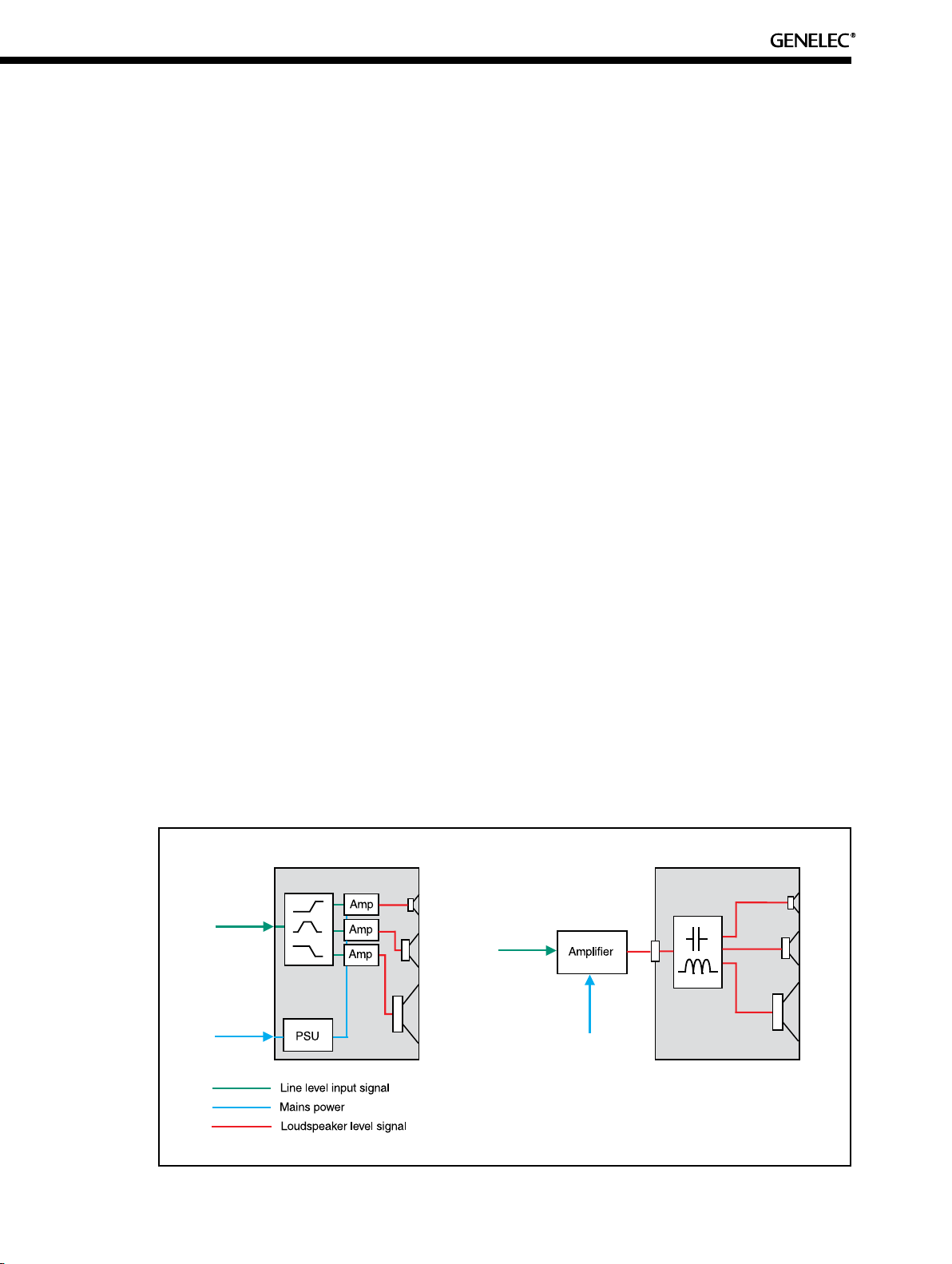
The concept of an active loudspeaker is simple;
• Remove the passive crossover components from the traditional loudspeaker design,
which are placed after the single amplifier on each channel.
• Design a custom electronic crossover, which is placed before the integrated amplifiers.
• Use as many amplifiers as there are drivers.
See Figure 1 for a block diagram of passive vs. active design. Active design ensures that each driver
(woofer, midrange and tweeter) has its own band-passed amplifier to which it is directly coupled and
matched. This concept greatly reduces distortion, improves dynamic headroom and frequency linearity
and increases the system total sound pressure level.
ACTIVE SYSTEM PASSIVE SYSTEM
Figure 1. - Active crossover BEFORE amplifier vs. Passive crossover AFTER amplifier
1
Page 7
2
It also allows the manufacturer to implement elaborated circuitry that protects the system from misuse
therefore increases reliability:
- Input Protection ensures that no signals above the acceptable input range enter and damage the
active electronics.
- Driver Protection allows for the maximum power output from the system while ensuring that the
drivers cannot be damaged by over driving the system.
- Thermal Protection shuts down the amplifiers if the acceptable operating temperature for the
electronics is exceeded. When the temperature drops sufficiently the system resets itself.
The Genelec active loudspeakers also feature proprietary Room Response Controls (see Section 4)
which help optimise the loudspeaker’s tonal characteristics once they are installed in a home theater.
Note that the amplifier can be located away from the enclosure but the loudspeaker/amplifier system is
still an active system because everything is designed to work together.
1.3 Directivity Control Waveguide
In 1983 Genelec designed a loudspeaker system that was radically unique in shape and acoustical
properties. The entirely smooth and curved enclosure provided no sound coloration of the drivers and
excellent control of the sound dispersion into the room. This was the birth of the revolutionary Directivity
Control Waveguide™ (DCW™) technology. Today the DCW™ is a waveguide in which is mounted the
high frequency (in three-way loudspeakers, midrange and high frequency) driver that controls the angle
of dispersion.
The aim of the DCW™ is to match the frequency response and directivity of the drivers in the loudspeaker leading to a great improvement on the performance of a direct radiating multi-way loudspeaker.
The result is an excellent match of the overall frequency response on and off axis. This control of the
directivity reduces incoming reflected sound at the listening position, thereby minimizing room coloration
and improving the entire sound stage imaging. The DCW™ technology allows for extremely high audio
consistency between very different Home Theater installations.
The DCW™ technology also improves the drive unit sensitivity even up to +6 dB, and therefore increases
the maximum sound pressure level as well as decreases the drivers’ distortion.
1.4 Home Theater Product Range
1.4.1 Products Overview
TM
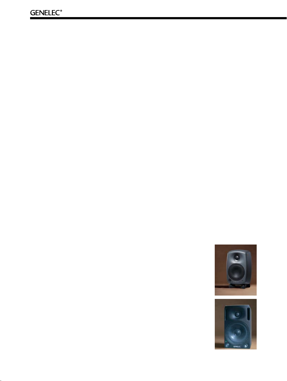
6020A
The 6020A is a very compact two-way bi-amplified system. It has a 4” woofer
and a ¾” metal dome tweeter housed in a robust aluminium enclosure. Each
driver has a directly coupled 20 W amplifier. This type of system is recommended for room volumes up to 65 m3 (2,300 ft3) and listening distances up to
2.4 m (8 ft).
HT205
The HT205 is a compact two-way bi-amplified system. It has a 5” woofer and a
¾” metal dome tweeter housed in a robust aluminium cabinet. Each driver has
a directly coupled 40 W amplifier. This type of system is recommended for room
volumes up to 75 m3 (2,600 ft3) and listening distances up to 3.0 m (10 ft).
Page 8
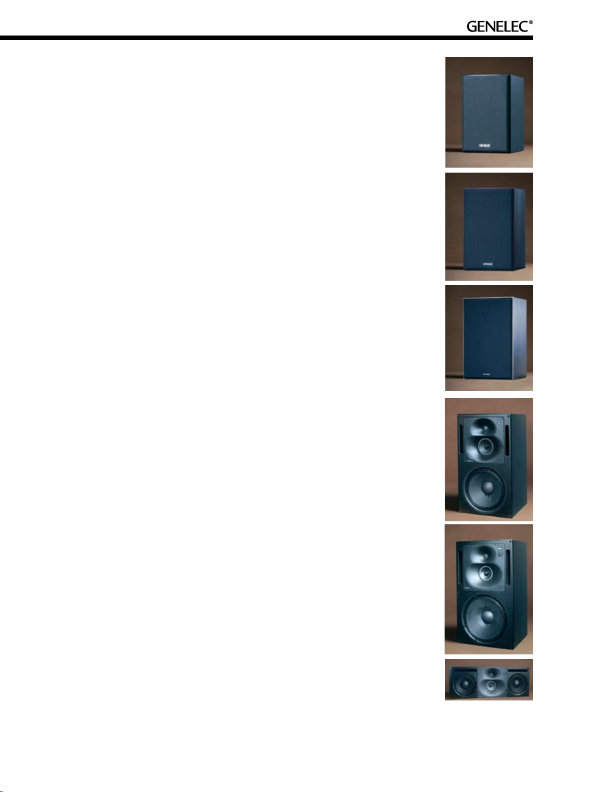
HT206B
The HT206B is a slightly larger bi-amplified system using a 6.5” woofer with an
80 W amplifier and a ¾” dome tweeter with a 50 W amplifier. The HT206B is
recommended for room volumes up to 85 m3 (3,000 ft3) and listening distances
up to 3.7 m (12 ft).
HT208B
The HT208B enclosure houses an 8” woofer and a 1” dome tweeter. Each
driver is directly coupled to an individual 120 W amplifier. The HT208B is recommended for room volumes up to 115 m3 (4,000 ft3) and listening distances
up to 4.9 m (16 ft).
HT210B
The Genelec HT210B is a very capable two-way bi-amplified system. It has a
10” woofer powered by a 180 W amplifier and a 1” dome tweeter directly coupled
to another 120 W amplifier. The HT210B is recommended for room volumes up
to 140 m3 (5,000 ft3) and listening distances up to 5.5 m (18 ft).
HT312A
The Genelec HT312A tri-amplified system is ideal for applications behind
perforated screens and can be run as full range loudspeaker. This 12” threeway system has a 180 W amplifier on the LF driver, 120 W on the proprietary
Genelec 5” midrange driver and another 120 W on the 1” dome tweeter. All
drivers are magnetically shielded. It is recommended for room volumes up to
175 m3 (6,200 ft3) and listening distances up to 6.5 m (21 ft).
HT315A / HT320AC
The HT315A / HT320AC models are substantial loudspeaker packages incorporating 400 W of amplification for the LF, 120 W for the MF and 120 W for the HF.
Practically identical in performance, the HT315 is a traditional three-way design
with a 15” bass driver and an integrated amplifier unit, whereas the HT320AC
is packaged in a slimmer enclosure with dual 10” bass drivers and a separate
amplifier unit in a rack mount chassis, making it suitable for applications where
space is limited. These loudspeakers are usually flush mounted into a wall for
an improved low frequency efficiency and a smoother midrange. All drivers are
magnetically shielded in both models. This type of system is recommended for
room volumes up to 250 m3 (8,800 ft3) and listening distances up to 7.6 m (25
ft).
3
Page 9
4
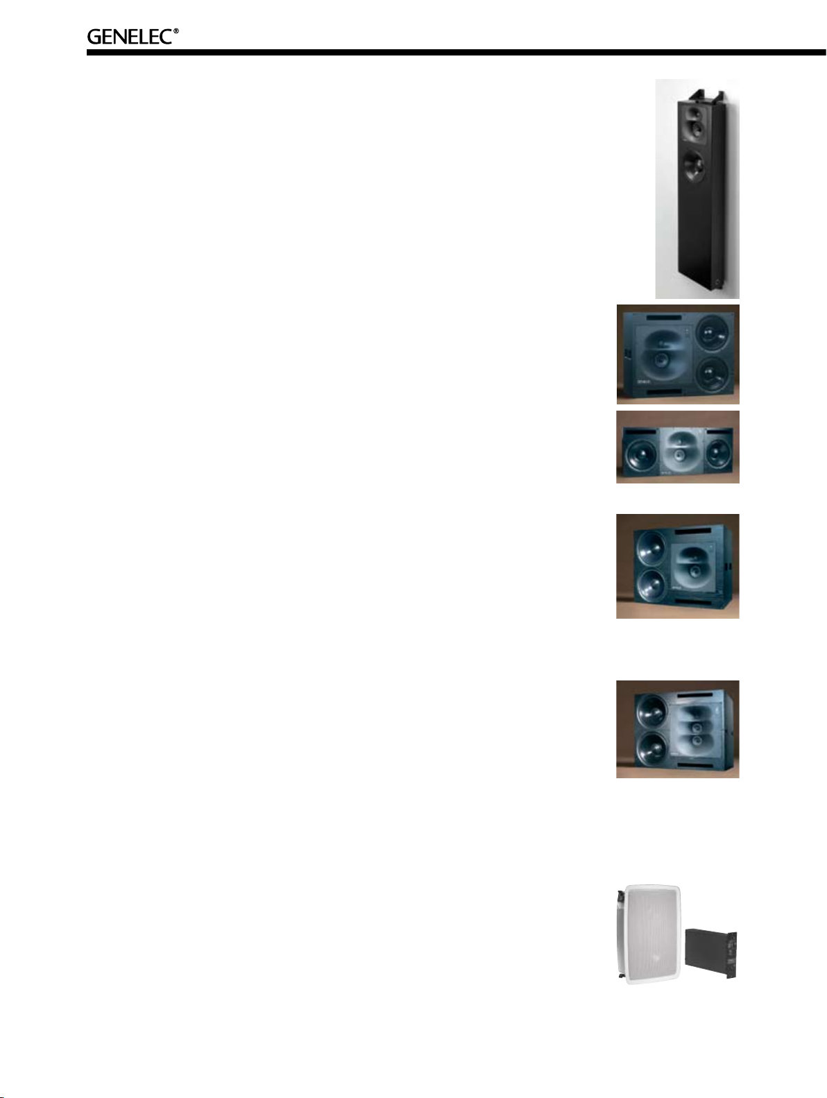
AOW312
The Genelec AOW312 On-Wall tri-amplified system is ideal for applications behind
perforated screens and can be run as full range loudspeaker. Architecturally it
offers minimum intrusion into designed spaces due to its shallow enclosure. This
12” three-way system has a 180 W amplifier on the LF driver, 120 W on the proprietary Genelec 5” midrange driver and another 120 W on the 1” dome tweeter.
All drivers are magnetically shielded. It is recommended for room volumes up to
175 m3 (6,200 ft3) and listening distances up to 6.5 m (21 ft).
HT324A / HT324AC
The HT324A is a dual 12” active loudspeaker incorporating 1.27 kW of amplification per system (400 W + 400 W + 350 W + 120 W). Systems of this size
and greater should be referred to Genelec for additional consultation. The ‘C’
in HT324AC stands for Center but this loudspeaker can also be used vertically
mounted in other locations where space is at a premium. This type of system is
recommended for room volumes up to 370 m3 (13,000 ft3) and listening distances
up to 8.5 m (28 ft).
HT330A
The Genelec HT330A features dual 15” bass drivers, a 5” midrange driver and a
1” metal dome tweeter that are powered respectively by 400 W + 400 W + 350 W
+ 120 W of amplification per system. Installation of this size should be referred to
Genelec for additional consultation and installation planning. This type of system
is recommended for room volumes up to 500 m3 (17,600 ft3) and listening distances up to 10 m (33 ft).
1036A
The 1036A comes with 3.1 kW of amplification per loudspeaker enclosure! Dual
18” bass drivers are powered by 2 x 1100 W amplifiers, the two 5” midrange drivers by a 600 W amplifier and the 1” compression driver by a 300 W amplifier. A
Home Theater project using such a large system presents structural challenges
that require planning and support in the construction phase, so contact your distributor for advice. This type of system is recommended for room volumes up to
850 m3 (30,000 ft3) and listening distances up to 15.5 m (50 ft).
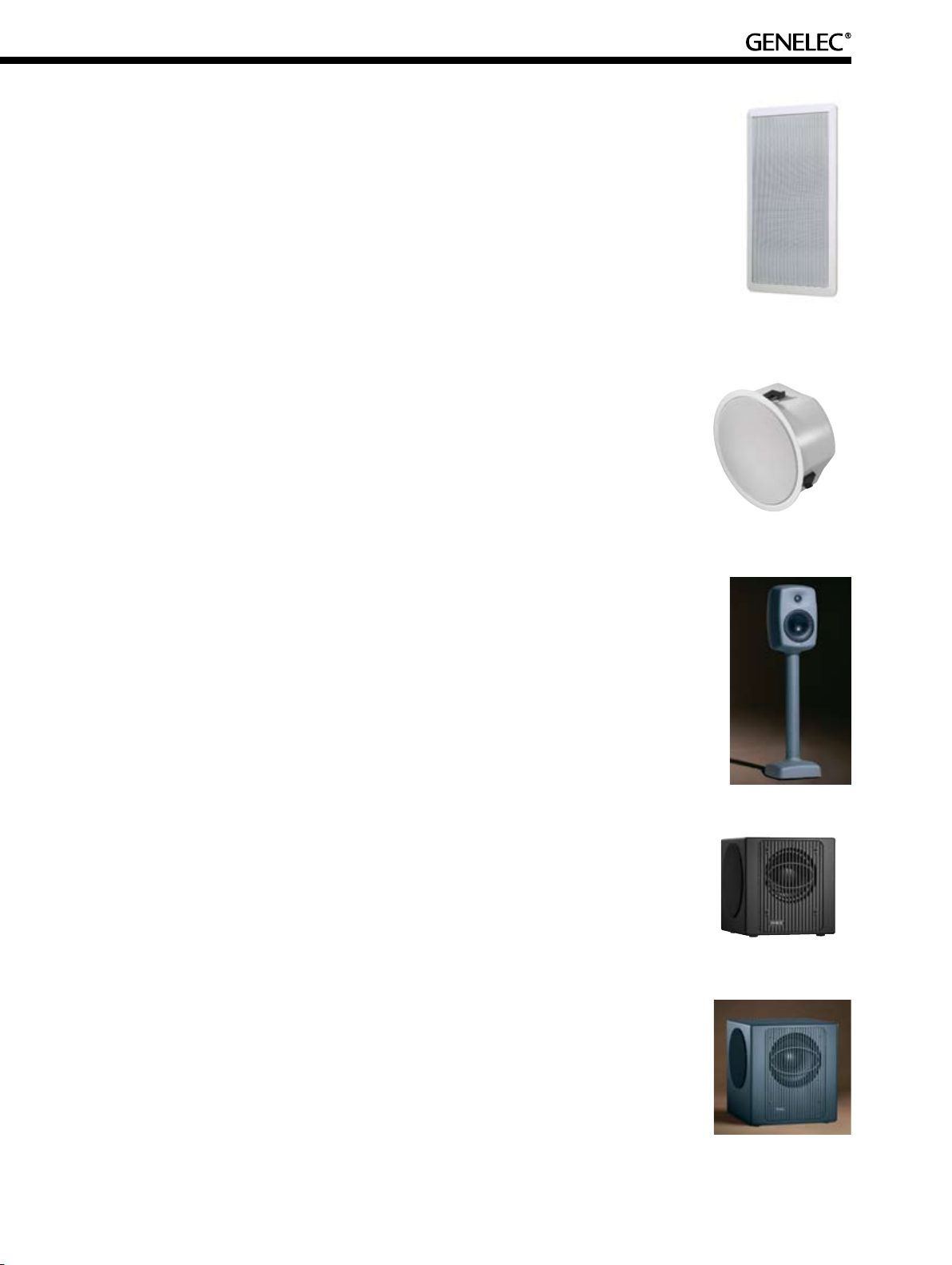
AIW25 In-Wall
The AIW25 is Genelec’s smallest In-wall loudspeaker consisting of a two-way
loudspeaker enclosure and a matched remote amplifier module RAM2. The 5”
woofer and the ¾” dome tweeter drivers are each connected to separate RAM2
amplifier module that can be rack mounted with its dedicated optional 4U high
RAM2-405 Rack mount adapter, or placed on a shelf or into a cabinet. Any 4-core
loudspeaker wire is then run to the loudspeaker enclosure. The AIW25 can be
used in demanding applications: as main L-C-R array of a Home Theater system,
for critical Stereo listening or rear/side channels of a medium sized, high quality
Home Theater. The loudspeaker fits into a standard 2 x 4” wall structure.
Page 10
AIW26 In-Wall
The AIW26 is Genelec’s answer for the need to hide powerful side and rear
loudspeakers. The AIW26 comes as a complete ported enclosure fitting into a
standard 2 x 4” wall structure. The 6.5” woofer and the ¾” dome tweeter drivers
are each connected to separate 120 W amplifiers housed in the RAM1 amplifier
module. This external unit can be placed in a rack with the source equipment,
placed on a shelf or hidden away near the loudspeaker enclosure. Any 4-core
loudspeaker wire is then run to the loudspeaker enclosure. The 4U high RAM1401 is an optional rack mount kit for the RAM1 amplifier module that can house
up to three RAM1 amplifier modules.
AIC25 In-Ceiling
The AIC25 In-Ceiling loudspeaker consisting of a two-way loudspeaker enclosure and a matched remote amplifier module RAM2. The 5” woofer and the ¾”
dome tweeter drivers are each connected to separate RAM2 amplifier module that
can be rack mounted with its dedicated optional 4U high RAM2-405 Rack mount
adapter, or placed on a shelf or into a cabinet. Any 4-core loudspeaker wire (the
cable length defines the required thickness) is then run to the loudspeaker enclosure. The enclosure requires only 158 mm (6 7/32”) of free depth inside the ceiling
structure and can easily be retrofitted into existing constructions.
6040A
The 6040A is a radically different product from Genelec with an emphasis on
design, form and acoustic performance. The 6040A can be utilized in either a
stereo system or high-tech multichannel configurations. This stylish enclosure,
inspired by designer Harri Koskinen from Finland, is made entirely from elegant
die-cast aluminium and will fit into any modern environment. The 7” woofer and
the ¾” dome tweeter drivers are each connected to separate 120 W amplifiers
housed in the loudspeaker’s base.
5050A Subwoofer
The Genelec 5050A Active Home Theater subwoofer is a powerful and very compact loudspeaker featuring one magnetically shielded active 8” driver mounted on
the front side and two 8” passive radiators, one on each side of the enclosure. A
70 Watt power amplifier is integrated into the subwoofer which has a frequency
response from 25 Hz - 120 Hz and delivers a maximum SPL output of 104 dB with
extremely low distortion levels.
HTS3B & HTS4B Subwoofers
Genelec’s Active Home Theater subwoofers, the HTS3B and HTS4B, deliver tight
and powerful bass down to 18 Hz. Both subwoofers share the same design layout
with one magnetically shielded active loudspeaker driver and two passive radiators. The HTS3B has a 10” driver and passive radiators powered by a 200 W
amplifier, whereas the HTS4B has 12” drivers and a 400 W amplifier. Both the
HTS3B and HTS4B have a frequency response from 18 Hz to 120 Hz and the
maximum SPL output is 113 dB and 117 dB respectively.
5
Page 11
6
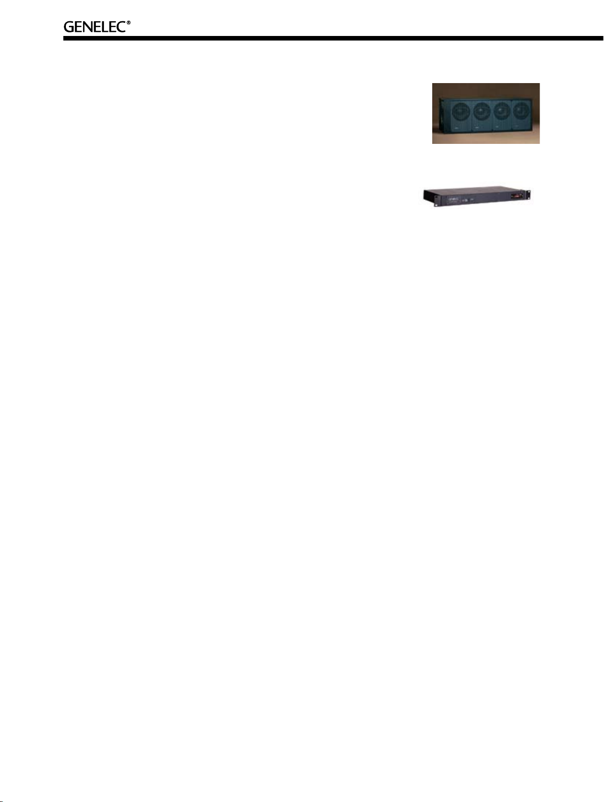
HTS6 Subwoofer
The HTS6 is designed to support Genelec’s three way loudspeakers in
medium sized or large Home Theater Systems. It features a 19 - 120 Hz
frequency response, four magnetically shielded 12” drivers, a total of 1000
W of amplifier power delivering a maximum SPL of 129 dB.
DI8A Active Balancer
The DI8A Active Balancer converts 8 unbalanced line signals to balanced
line signals thereby reducing their susceptibility to electronic interference.
Most processors available today have unbalanced RCA outputs and all of
the Genelec Home Theater Systems have XLR balanced line inputs so the DI8A is an excellent way to
ensure noise free transmission of the signal. Gain adjustment switches allow the gain of each channel to
be increased by +6 dB if the output level of the processor is insufficient for the loudspeaker input. Channel 8 also features dual outputs.
1.4.2 Enclosure Colours and Finishes
Different enclosure finishes are available depending on the product type: The die-cast aluminium enclosure of the 6020A is only available in black, the HT205 is available in white, silver, grey and black finishes.
The HT206B, HT208B and HT210B wooden enclosures are only available in black finish. The 6040A is
available in silver finish. The AIW25 and AIW26 In-Wall and the AIC25 In-Ceiling loudspeakers can be
spray painted to match any colour scheme. All three-way active Home Theater loudspeakers are available
in black finish only as the enclosures are normally hidden. The 5050A, HTS3B and HTS4B subwoofers
are available in dark grey mat finish, while the HTS6 subwoofer has a durable painted black finish.
2 Planning The Installation of Genelec Products
The room size and the listening/viewing distance are the two criteria that drive any successful surround
sound environment. Because Genelec designs and manufacturers many different sized models, there is
a loudspeaker available to fit into any sized environment.
2.1 Terms used in this Guide
There are two terms used in this guide that should be defined before reading any further:
Loudspeaker - The physical device that makes the sound in the listening room (in this case, amplifier, crossover, enclosure and drivers).
Channel - The signal fed into the loudspeaker as decoded by the surround sound processor.
In 5.1 discrete surround sound systems there are five full bandwidth main channels (Left, Center, Right,
Rear Left and Rear Right) and a band limited channel (LFE). There is an important distinction here;
for example, the center channel is the signal that represents the sound that should be reproduced by
the center loudspeaker. Another more complicated example is that the LFE channel is often called the
‘subwoofer channel’. This is only true in the movie industry where a subwoofer is connected directly to a
LFE channel and bass management is not used. In Home Theater, the subwoofer is used to reproduce
some, or all, of the LFE channel and, if bass management is used, some of the main channels too. The
signal that feeds the subwoofer is then often called the ‘subwoofer channel’. Other surround sound systems have more channels, which are explained later.
Page 12

2.2 Room Size Specification
Probably the first known factor when designing a new Home Theater is the space where the Home
Theater will be. Product selection is based upon the cubic volume of the listening environment. If it is an
irregular shaped room, it is best to use the larger set of dimensions, that is, to play on the safe side.
See Section 2.10 Selecting the Right Model for a chart to select the correct loudspeaker model for a
given room volume.
2.3 Listening Distance
One of the first decisions that should be made is what is the size of the video image and how far is
the screen from the center of the seating area? This will affect which Genelec models are selected. All
Genelec models (except subwoofers) feature the DCWTM (Directivity Control WaveguideTM) technology.
The DCWTM is used to control the dispersion pattern of the tweeter driver (and the midrange driver in
three-way systems) in both the horizontal and vertical axis. Moving to larger models in the Genelec
product line increases the possible distance from the loudspeaker to the listening area as the dispersion
characteristics are optimized for longer listening distances.
See Section 2.10 Selecting the Right Model for a chart to select the correct loudspeaker model for a
given listening distance.
2.4 Front Loudspeakers - A Model for Every Requirement
The Genelec Active Home Theater range is a little different than the offering of conventional hi-fi loudspeaker manufacturers. The Genelec range is application specific. In other words, if your room is a certain
size, the listening distance is a certain length or a particular SPL is required in the listening area, then
there is a model in the product line to satisfy most needs. The Genelec range has a consistent design
philosophy from the 6020A all the way up to the 1036A. This is clear from the outside but is also true
of the parts that cannot be seen. Modern design methods give modularity benefits that enable efficient
manufacturing techniques to be used in production. This ensures that all the products have a consistent
performance straight out of the box and are reliable in use.
2.5 Center Channel Loudspeakers
There are three main factors to consider when choosing and using center loudspeakers:
2.5.1 Center Loudspeaker Design
Conventional two-way ‘center’ loudspeaker designs are inherently compromised in the power response
(the total radiated energy into the room). The driver spacing leads to horizontal off-axis cancellations
around the high-pass crossover in the horizontal direction. In addition, the use of three drivers positioned
in a line narrows the directivity in the plane of the drivers, i.e. horizontally. This severely compromises the
sound quality for people sitting to the left and right of the center of the room, i.e. off-axis.
Given these two-way center loudspeaker design compromises and the recommendations from Dolby,
DTS and others that, in an ideal surround sound system, the front loudspeakers are all the same for
good timbre matching, the best choice for a center loudspeaker is another loudspeaker that it is the same
as that used for the left and right loudspeakers. For example, the best match for an HT208B is another
HT208B!
In three-way designs, the bass/midrange driver crossover frequency is much lower so the above acoustical problems are far less significant as the DCWTM can be rotated so that the horizontal directivity is
maintained in the midrange/treble driver crossover region.
7
Page 13
8
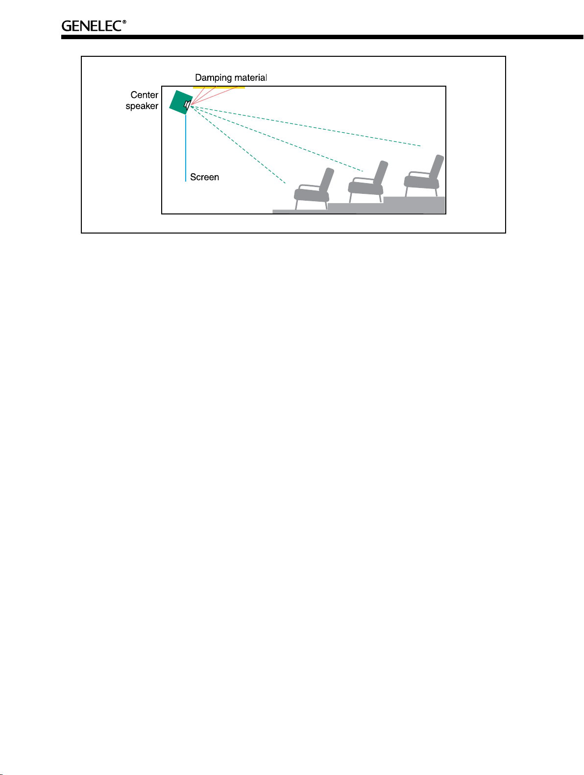
Figure 2. - Mounting the center loudspeaker above an unperforated projection screen
2.5.2 Center Loudspeaker Enclosure Location
Ideally, the center loudspeaker enclosure should be mounted at the same height as the picture so that the
sound comes from the same place as the picture, however this is not always possible as demonstrated
in the following two cases:
Perforated projection screens
The loudspeaker enclosure can be mounted in the center of the picture but there is a compromise
to the frequency response - see Graph 1 in Section 3.7 Acoustically ‘Transparent’ Screens. Some
perforated projection screens are acoustically more transparent than others, however, this should
be weighed against corresponding compromises in the picture quality.
Large CRT’s, rear projecting displays and unperforated projection screens
The loudspeaker enclosure should be placed ABOVE the screen. This will reduce the effects of the
floor reflection as the reflection distance and angle are both increased. Doing this will cause the
ceiling reflection to become significant but this can be easily treated by adding some thin (5 cm / 2”
rock wool) damping material to the ceiling - see Figure 2. The loudspeaker enclosure should never
be placed behind an unperforated projection screen - See Section 3.7 Acoustically ‘Transparent’
Screens.
2.5.3 Center Loudspeaker Enclosure Orientation
In the case of Genelec’s larger three-way center channel systems, the bass/mid crossover frequency is
much lower so the horizontal off-axis cancellations do not occur here. There will however be a cancellation
at the mid/treble driver crossover but this can be overcome by orienting the DCWTM vertically so that the
crossover cancellation is then in the vertical direction, i.e. not audible due to the fixed listening height.
Two-way systems should normally be positioned vertically to avoid audible off-axis cancellations at the
crossover frequency. When positioned in this way, the crossover cancellation will be in the vertical direction (not a problem as the listening height is fixed) and the horizontal listening window will be wide and
clean of abnormalities. However, if there is limited space, for example, when large CRT or unperforated
projection screens are used, then the loudspeaker enclosure can be placed horizontally but with this
known compromise. See Section 2.10 Selecting the Right Model for a table on which center loudspeaker
to select for a given room volume and listening distance.
Page 14

2.6 Surround Loudspeakers - Dipoles vs. Direct Radiators
When Dolby Surround and Dolby Pro Logic were the sole surround formats, the idea of using dipole
radiators in the rear was to create a diffuse sound field in the listening environment for the ambient
information. Today, however, there are three good reasons NOT to use this type of loudspeaker design
for the rear channels:
• Dipole loudspeakers have a limited low frequency bandwidth, which is fine for use in matrix
surround sound formats, such as Dolby Surround and Dolby Pro Logic where the surround
channel bandwidth is also limited (100 Hz to 7 kHz). However, in discrete surround sound
formats, such as Dolby Digital and DTS, the rear channels have an extended bandwidth from
20 Hz to 20 kHz. In addition, in the production stages, direct radiating loudspeakers are
used that typically extend down to 40 or 50 Hz. Most dipoles used for surround applications
do not extend much below 100 Hz so real impact in the bass is absent, however, there is
envelopment in the mid bass and higher frequencies.
• Often the listening environment is absorbent in the mid range so the effectiveness of dipole
radiation is lost. In fact, the effect of dipole loudspeakers is entirely dependent on the
acoustics of the room that often vary considerably from one room to the next.
•
The advent of multi-channel music formats, such as SACD and DVD-Audio, depends on
greater usage of direct radiators as sides and rears in order to get the intended
performance. These music mixes are monitored in studios with direct radiating
loudspeakers, so playback through them in the home will create the result the engineer,
producer and artists intended.
A Genelec direct radiator, whose off-axis response is smooth and natural sounding, will provide a good
solution for the new extended bandwidth surround sound formats (SACD and DVD-Audio) and still work
in any sonic environment. In addition, 7.1 and other such ‘formats’ (for example, Logic 7 is actually a post
processing technique added to a 5.1 signal) have changed room design techniques and so dipoles are
no longer as suitable as they once were. The use of direct radiators will yield better front to back effects
panning and more detailed playback of soundtrack events.
See Section 2.10 Selecting the Right Model for a table to select surround models for a given room volume
and listening distance.
2.7 Subwoofers - Loud and Low
The primary function of a subwoofer is to move lots of air. Ideally, it should have a low cut-off frequency
(<20 Hz for movie material, <35 Hz for music material), no distortion and play extremely loud. To play loud
is easy - use big amplifiers. To play low is easy - use big drivers and large enclosure. To play loud AND low
is hard, especially when low distortion is also desired. Do not be fooled by statements such as, “It has a
1200 W amplifier so it must be loud!” as this is only part of the story. Poor efficiency in the acoustics can
make such a system quieter than a 12 watts system.
Number of
subwoofers
1 0 104 113 117 129
2 6 110 119 123 135
3 9.5 113.5 122.5 126.5 138.5
4 12 116 125 129 141
Table 1. - Adding Subwoofers Increases the Maximum Peak SPL Output
See Section 2.10 Selecting the Right Model for a table to select subwoofer models for a given room
volume and listening distance.
Increase in
SPL, dB
SPL for 5050A
and multiples
SPL for HTS3B
and multiples
SPL for HTS4B
and multiples
SPL for HTS6
and multiples
9
Page 15

10
Genelec has worked very hard to have an efficient system that has appropriately specified amplifiers
AND has very low distortion. More subwoofers can be added to increase the maximum SPL of the bottom
end of the frequency response in a larger system. See Table 1 for details about multiple subwoofers.
For an even lower distortion, just add more subwoofers to the Home Theater. For example, adding a
second subwoofer to a system allows the input sensitivity to be decreased by 6 dB so each subwoofer
plays 6 dB quieter but the overall level in the room is the same. This will reduce the distortion by more
than 6 dB for the same replay level, as distortion is non-linear with respect to SPL. Using two smaller
subwoofers instead of one large unit may also be preferable for space reasons. See Table 1 for details
about multiple subwoofers.
2.8 System Building - How to Mix and Match
Now is a good point to discuss selection of an entire system. If one adheres to some of the basic guidelines set by Dolby Laboratories, DTS and other standardization organizations, then the best possible
configuration is 5 identical loudspeakers all around for 100% timbre matching. Of course, this is not
always practical but as 5.1 music has become more available, this aspect of system design becomes
more important and therefore common practice.
In Section 2.10, Selecting the Right Model, there is a table which can be used to find which loudspeaker model is appropriate for a given room volume and listening distance. Some suggested side
and rear loudspeaker solutions are given but the final choice will also be based on the listening preferences of the customer (what program material they prefer and how loud they play it), the space
available in which to place the loudspeaker enclosure and budget. The AIW25 and AIW26 In-Wall
loudspeakers have many applications even together with quite large Genelec models, however they
will need to be used in multiples to fill large rooms.
7.1 systems are becoming more common in Home Theater, so sides as well as rear channels are almost
the norm. Multiple loudspeakers are suitable in very large 7.1 systems too, so a set of 8 x AIW26 could
be used in a very large system.
2.9 How Room Acoustics Can Affect Model Selection
Room acoustics is an area of Home Theater that is often overlooked. It is important and challenging but
with some consideration, a good sound can be the result. There is insufficient space in this document to
explain all the issues associated with good room acoustics so two extremes are presented below that
may influence the selection of one model over another:
• If the room is heavily damped (thick carpeting, heavy curtains and lots of upholstered
furniture) there will be a loss of energy in the midrange frequencies. On the positive side, it
should be remembered that an absorptive room usually results in more accurate imaging.
If there is any doubt in the choice between two models based on the listening distance or
room volume then select the larger model that offers a higher maximum SPL output.
• Conversely, if the room is minimally furnished and has many hard surfaces with little
absorption (although that would be a rarity in a dedicated home theater), then it may be
possible to step down a model in the range. Such a room will tend to be highly reflective and
support the loudspeakers’ output, so some adjustment of the Room Response Controls will be
necessary - see Section 4.2.2 Using the Room Response Controls. Contrary to the
well-damped room, the imaging will be rather diffuse.
There is more on room acoustics in Section 5 Room Construction and Acoustics.
Page 16

Maximum
Room
Volume
m3 (ft3)
65 (2,300) 2.4 (8) 1.8 (6) 6020A 6020A 5050A
75 (2,600) 3.0 (10) 2.2 (7) HT205 / AIW25 HT205 / AIW25 HTS3B
85 (3,000) 3.7 (12) 2.8 (9.2) HT206B / AIW25 HT205 / HT206B / AIW25 HTS3B
115 (4,000) 4.9 (16) 3.5 (11.5) HT208B / AIW26 HT206B / HT208B / AIW26 / AIW25 HTS4B
140 (5,000) 5.5 (18) 4.5 (15) HT210B HT208B / HT210B / AIW26 / 2x AIW25 2x HTS4B*
175 (6,200) 6.5 (21) 5 (16.4) HT312A / AOW312 HT208B / HT210B / AIW26 2x HTS4B*
250 (8,800) 7.6 (25) 6.2 (20.4) HT315A / HT320AC HT210B / 2x AIW26 HTS6
370 (13,000) 8.5 (28) 7 (23) HT324A / HT324AC HT312A / AOW312 / 3x AIW26 2x HTS6**
500 (17,600) 10.0 (33) 8 (26.3) HT330A HT315A / 2x AOW312 / 4x AIW26 2x HTS6**
850 (30,000) 15.5 (50) 11 (36) 1035B / 1036A HT315A / 2x AOW312 / 4x AIW26 3x HTS6**
Maximum
Listening
Distance
m (ft)
Typical
Listening
Distance
m (ft)
Front
Loudspeakers
Side and Rear Loudspeakers
(per channel)
Subwoofer
Table 2. Active Home Theater System Selection Table
* Using multiple smaller subwoofers instead of one larger one may be preferable for space reasons.
** Such recommendations assume that the system is bass managed at 40Hz. More subwoofers may be required for
a higher crossover frequency. Consult Genelec for detailed subwoofer solutions for this sized installation.
Figure 3. - Examples of balanced loudspeaker combinations for different sized applications
11
Page 17

12
2.10 Selecting the Right Model
Use the following chart as a guide for product selection and follow these three simple steps:
• Calculate the room volume and find the highest row in the table where the value of “Maximum
Room Volume” is not smaller than the actual room volume.
• Measure the listening distance to the center of the listening area and find the highest row in
the table where the value of “Maximum Listening Distance” is not shorter than the actual
listening distance.
• If there are two different rows selected in the previous two steps, select the loudspeakers
from the row that is lowest in the table, i.e. the larger of the two if there are two different lines
recommended.
Note: these recommendations are for the SMALLEST system that can be expected to give a good
theatrical experience. Larger systems offer more impact and headroom, so do not be afraid to select
larger models in the range than those indicated. The main thing to be concerned about when up rating
the system is to keep the whole system in balance, so do not select a 1036A for the front wall and have
6020A’s for sides and rears!
Loudspeaker Selection Examples:
• If the room is 5 m (16½’) wide, 9 m (29½’) long and 3 m (10’) high, then the room volume is
135 m
3
(4900 ft3). This limits the loudspeaker selection to HT210B or larger. If the listening
distance is then measured to be say 5 m (16’ 5”) then the selected front loudspeakers are
confirmed as being HT210B or larger.
• If the room is 6 m (19½’) wide, 14 m (46’) long and 2.5 m (8’) high, then the room volume is
210 m
3
(7200 ft3). This limits the loudspeaker selection to HT315A or larger. If the listening
distance is then measured to be say 8 m (26’3”) then the selected front loudspeakers should
be HT324A or larger as the HT315A should only be used up to 7.6 m (25’).
If there are any doubts about product selection for a particular room then please contact Genelec for
advice. It is better to specify the correct system the first time so there are no problems after the room is
finished as unnecessary fixes affect the reputation of the installer and Genelec.
2.11 Electronics Panel Controls - Features and Functions
Each Genelec Home Theater loudspeaker has an extensive set of controls located on the enclosure’s
electronics panel. Each model features a combination of the following controls (see specific product data
sheet for detailed specifications).
Room Response Controls
The Bass Roll-off and Bass Tilt controls allow the low frequency
response of the loudspeaker to be reduced to compensate for LF
loading when the loudspeaker is placed in a corner or against a
wall respectively. The two-way systems’ Treble Tilt allows the treble
to be controlled to compensate for the high frequency acoustic
conditions in the room. Even more control is available in the 1035B
and 1036A.
The level controls of the larger three-way loudspeakers include
Bass Level, Midrange Level and Treble level. These controls allow
the driver output levels to be controlled so that the loudspeaker
can be tuned to the room.
Page 18

The ‘Phase’ control featured on all subwoofers enables the alignment of the main loudspeaker/
subwoofer combination in the time domain. The phase can be adjusted between 0, 90, 180 and 270
degrees.
Input Section
All loudspeaker models have an input sensitivity trimmer - except the 6020A and HT205 which
have a front-mounted level control. The two-way loudspeakers and subwoofers feature an unbalanced non-inverting RCA input as well as a balanced line XLR input. Large three-way loudspeakers only have an XLR input whereas the subwoofers have an additional XLR link out connection.
Power Section
The mains power section comprises a voltage selector (country dependent voltage selection), an
IEC mains input socket and an On/Off switch.
Remote Control Section
Genelec Home Theater products have a power management section that allows the installer to
enable or disable the ‘Autostart’ function as well as the ‘Power’ and ‘Standby’ indicator LED’s on
the front of the loudspeaker enclosure. Two types of remote switching terminals are also included:
a 12V trigger function and a contact closure function operated via an external switch or relay as
is often found on home theater automation systems. For details of the features provided in each
model, see Table 3.
Models ’Autostart’
6020A
HT205
HT206B
HT208B
HT210B
AIW25 / AIC25
AIW26
HT312A / AOW312
HT315A / HT320AC
HT324A / HT324AC
HT330A
1035B / 1036A
5050A
HTS3B
HTS4B
HTS6
Function
Yes N/A N/A N/A
N/A N/A N/A N/A
Yes Yes Yes Yes
Yes Yes Yes Yes
Yes Yes Yes Yes
Yes Yes Yes N/A
Yes Yes Yes Yes
Yes Yes Yes Yes
Yes Yes Yes Yes
N/A N/A Yes N/A
N/A N/A Yes N/A
N/A N/A N/A N/A
Yes N/A N/A N/A
Yes N/A Yes Yes
Yes N/A Yes Yes
Yes N/A Yes Yes
Power/standby
LED On/Off
Table 3. - Power Management Features vs. Models
12 V Trigger
Remote
Relay Switch
Remote
2.12 Audio Cables and Wiring
2.12.1 Electrical Requirements
The nature of the active technology in the product design means that the electrical power requirements
are generally much lower than a passive system and amplifier with an equivalent SPL output. Idle currents are kept low and long-term full power output is limited by driver protection. However, some care
should be taken that the start-up current is kept under control, so sometimes a staged turn on may be
necessary for large systems without soft start, for example, 7x HT312A and 2x HTS4B. Table 4 lists
13
Page 19

14
Power Consumption, W Current Requirements, A
Models
6020A 5 50 0.3 / 0.6 0.22 / 0.44
HT205 9 80 0.5 / 1.0 0.35 / 0.70
HT206B 20 100 0.6 / 1.2 0.43 / 0.86
HT208B 30 160 1.0 / 2.0 0.70 / 1.40
HT210B 50 200 1.2 / 2.4 0.87 / 1.74
AIW25 / AIC25 10 80 0.5 / 1.0 0.35 / 0.70
AIW26 30 160 1.0 / 2.0 0.70 / 1.40
HT312A / AOW312 50 300 1.8 / 3.6 1.30 / 2.60
HT315A / HT320AC 60 500 Soft start 2.17 / 4.35
HT324A / HT324AC / HT330A 70 1000 Soft start 4.35 / 8.70
1035B / 1036A 150 3500 Soft start 15.22 / 30.43
5050A 11 120 0.74 / 1.47 0.52 / 1.04
HTS3B 16 200 1.2 / 2.4 0.87 / 1.74
HTS4B 16 250 1.54 / 3.0 1.09 / 2.18
HTS6 60 1000 Soft start 4.35 / 8.70
Idle Full Output At Start-up
230V / 115V
At Full Output
230V / 115V
Table 4. - Electrical Power Requirements
the individual channel requirements for both idle and full power output and the current requirements for
start-up and full power output.
The start-up current peak is generally higher than the full power output current but because it is very
short, only a rough value can be given. The slow blow fuses commonly used in residential properties do
not notice short start-up peaks, for example, approximately twenty HT205’s can be connected to a 10 A
fuse and a single power switch without the start-up current blowing the fuse.
2.12.2 Cable Requirements
Genelec respects the dealer’s right to sell customers any good quality cable with good quality terminations that they feel is suitable for the installation. However, a few observations are detailed below:
Loudspeaker cables are not required in Genelec systems (except for the AIW26 and AIW25 In-Walls and
AIC25 In-Ceiling) as the amplifier is, in smaller systems, built into the loudspeaker enclosure. In larger
systems where the amplifier is separated from the enclosure, special Genelec cables are supplied with
loudspeaker system. Custom-made cable lengths are available but, in general, the cable length should
be minimized.
Electrically the main requirements of line level cable are that it has a low capacitance (to avoid a high
frequency roll-off on long cable runs), that it is not microphonic (makes an audible noise through the
loudspeaker when it is moved) and that it is long enough to reach the loudspeaker!
2.12.3 Signal Cable Lengths
Most processors these days have plenty of output level to drive the signal up to about 10 m (30 ft) without
much difficulty. The problem is that they often have unbalanced outputs so that the signal is susceptible
to electrical interference along the entire cable length. In some cases, this may not be a problem if careful consideration has been paid to the physical placement of the cabling away from electrical sources of
noise. In the case of the 6020A, HT205, HT206B, HT208B, HT210B loudspeakers, AIW25 and AIW26
In-Walls, AIC25 In-Ceiling and 5050A, HTS3B, HTS4B & HTS6 subwoofers, unbalanced non-inverting
RCA input connectors are provided together with the XLR input connectors. These are ‘either/or’ connections so never use both at the same time.
Page 20

All the larger models (HT312A, AOW312, HT315A, HT320AC, HT324A, HT324AC, HT330A, 1035B and
1036A) have XLR balanced line inputs only.
It is always preferable, where there is a choice, to use XLR balanced line cabling due to increased
noise immunity on long cable runs around the room, even in electrically clean environments. Only the
most expensive surround sound processors have balanced outputs and, in some cases, only some of
the outputs are balanced so a method must be used to convert the unbalanced RCA to a true balanced
line signal. Therefore, Genelec has created the DI8A Active Balancer to solve these cabling problems
and to make installations simpler. Genelec recommends that this unit is specified whenever possible in
a Genelec installation. In addition to eliminating RF problems, it should also prevent ground loop hums.
See Section 1.4 1. DI8A.
2.12.4 Remote Control Cables
Any standard 2 core cable can be connected to the remote control inputs. There are 4 pins on the loudspeaker remote control inputs that work in two groups (The RAM2 amplifier for AIW25 and AIC25 has
only two pins for the 12 V trigger type control). Do not attempt to use both remote control function at the
same time. Note also that the remote control function will override the ‘Autostart’ dip switch function on
the electronics panel when the ‘Remote Control’ switch is selected.
12V DC Remote
Pin 1 and 2 can be connected to a 12V DC Remote switch. If Pin 1 is set to +12 V the loudspeaker
is “ON”. Setting Pin 1 to 0 V forces the loudspeaker into “Standby” mode. Pin 2 is the ground connection.
External Switch or Relay
Pin 3 and 4 can be connected to an external switch or relay. If the switch/relay contact is closed,
then the loudspeaker is ‘On’ and when open it is then in ‘Standby’ mode.
2.12.5 Wiring the Cables
The input stages of all Genelec loudspeakers are designed to the highest standards, as used by broadcasters and music studios all over the world. They have electronically balanced inputs. In other words,
transformers are not used so this means that the system is capable of electrically interfacing to either
balanced or unbalanced sources. There are five possible ways to connect surround sound processors
to Genelec loudspeakers:
XLR output - RCA input
This is not recommended as it is much better to use an XLR - XLR connection - see below.
XLR output - XLR input
This method is preferred over all the others mentioned in this section. As most surround sound
processors do not offer XLR outputs, a DI8A Active balancer can be used to convert the RCA
output of the processor to an XLR balanced line output.
RCA output - RCA input
This is the conventional method used in consumer electronics for connecting equipment. It is a
satisfactory method for short cable lengths, for example, between the DVD and processor or for the
front loudspeakers where the equipment is also located at the front of the room. It is susceptible to
electrical interference and is not recommended for longer cable lengths over 10 m (30 ft).
RCA output - XLR input
This connection method offers some improvement over the RCA-RCA method as the noise immunity is improved. It is not a truly balanced connection so some cable manufacturers refer to it as
‘semi-balanced’. The 2-core method shown below is preferred over the 1-core method as it gives
increased noise immunity and less signal distortion. It is important that all of the connections are
15
Page 21

16
Figure 4. RCA unbalanced line to XLR balanced line wiring diagram
Figure 5. High level amplifier output to XLR balanced line input wiring diagram
NOTE: For 100 W amplifiers, double the resistor wattage values shown in the diagram
made otherwise there could be a loss of input signal level (e.g. XLR pin 3 left floating will result in a
thin and weak sound) or induced hum (e.g. chassis ground and audio ground connected together)
due to ground loops. Note: do not connect the XLR chassis to XLR pin 1, as this will compromise
the RF immunity of the loudspeaker’s electronics. It is preferable to make the pin 3 to pin 1 connection at the RCA end so that noise immunity is maximized. Use the wiring conventions shown in
Figure 4.
It is possible to find pre-made RCA-XLR cables but be sure to identify if the tip of the RCA end is
connected to pin 2 at the XLR end and that pin 3 is connected to pin 1. Some cables are wired differently: the RCA tip is connected to XLR pin 3. Although both types work, mixing them in an installation will cause some loudspeakers to be out of phase compared to others. The logical choice is to
select the type where the RCA tip is connected to XLR pin 2 as this wiring configuration does not
invert the phase. This is then compatible with conventional XLR-XLR connections. Also, the XLR
chassis to XLR pin 1 connection should be checked to see that it has not be made.
Page 22

Loudspeaker level output - XLR input
This method can be used when preamplifier outputs are not available on the surround sound
processor (a common situation on cheaper receivers). Do not connect the loudspeakers directly to
an amplifier output, as the loudspeaker’s input stage will be damaged. Use the simple attenuator
design shown in Figure 5. Be sure to make all of the connections shown to minimize noise interference. The 2-core method is preferred over the 1-core method as it gives increased noise immunity
and less signal distortion. It is important that all of the connections are made otherwise there could
be a loss of input signal level (e.g. XLR pin 3 left floating) or induced hum (e.g. chassis ground
and audio ground connected together) due to ground loops. Note: do not connect the XLR chassis to XLR pin 1, as this will compromise the RF immunity of the loudspeaker’s electronics. Do not
use this method on bridged amplifier designs as the amplifier may be damaged. Loudspeaker wire
should be used between the amplifier and the attenuator. Screened wire should be used from the
attenuator to the loudspeaker input. The attenuator box can be metal or plastic and one attenuator
is required per loudspeaker channel.
2.13 Operating Voltage and Power Requirements
Each Genelec Home Theater loudspeaker is delivered with a mains power cable with an appropriate
plug for that country. The active electronic and power amplifiers are meant to be connected to an earthed
mains connection (3-core mains).
Make sure that the correct supply voltage corresponding to your country is clearly indicated on the product before switching the power ON. Because of possible supply voltage variation in certain countries and
areas, it is advisable to make sure that this voltage swing does not go beyond the tolerances mentioned
below:
Residential and Home Theater Speaker Systems operating voltage range:
Standard model (USA - Europe): 115/230 V +/- 10 %
Japanese model: 100/200 V +/- 10 %
If it is expected that the supply voltage will vary outside the 10 % tolerance, it is recommended that a
good quality power supply regulator is used.
2.14 Protection Circuits
Genelec active loudspeakers have custom designed protection circuits that are optimized for each model.
The purpose is to protect the drivers from severe abuse that would otherwise decrease the system’s reliability. The characteristic sound of activated driver protection is a short loss of high (or low) frequency or
the whole signal completely for short, but audible periods. This is not signal compression. If the customer
is often experiencing this phenomenon, the system is under specified for the required maximum sound
pressure level in this particular room. In this case, the loudspeakers should be replaced with bigger
models that can deliver the desired SPL without overloading.
2.15 Troubleshooting
Genelec has a reputation for making high quality and reliable products but occasionally ‘problems’ arise
that require troubleshooting. If there appears to be a problem with the loudspeaker, it is often possible to
isolate problems between the amplifiers or the drivers since the system is integrated.
If the loudspeaker is plugged in and turned on but there is no sound, the chances are that it is the amplifier. If the lights are on, then it could still be the amplifier but it could also be the driver(s). When in doubt,
the amplifier of a known good system can be quickly swapped over to the problem system to see if the
drivers are working. If they are then the problem is in the amplifier.
17
Page 23

18
It cannot be stressed enough that the vast majority of loudspeaker problems turn out to be acoustical
or cabling problems. PLEASE CHECK THESE FIRST, then contact the local Genelec distributor for
advice.
3 Practical Installation Considerations
3.1 Main Loudspeaker Positioning
The ideal loudspeaker placement is often compromised when working within the client’s wishes and room
design restrictions. Often sound quality is third on the list after the room aesthetics and video requirements, however, with some attention to detail, it can be close rather than distant third.
DVD’s are normally mixed in studios that conform to the ITU standard ITU-R BS.775-1 “Multichannel
stereophonic sound systems with and without picture” (Geneva, 1992-94). The closer a Home Theater
can get to this standard the better the audio result will be. A few of the more important recommendations
found in this international standard are presented and discussed below:
3.1.1 Angles
ITU Recommendation:
Left and right are positioned 30º from the center and the rears are positioned 110º ± 10º from the
center. The loudspeakers should then be angled so that they point towards the optimum listening
position - see Figure 6.
In Practice:
These angles are generally not respected in Home Theaters. The center loudspeaker is usually
in the correct place but the left and right loudspeakers are positioned according to the size of the
screen (a practice inherited from the movie theater ‘standards’). Multiple loudspeakers are used for
the rear channels to increase coverage in the listening area and are positioned wherever is most
convenient on the side and/or rear walls.
3.1.2 Distance
ITU Recommendation:
All loudspeakers should be equidistant from the “sweet spot.”
In Practice:
In Figure 6, it can be seen that it is difficult to place the left, center and right loudspeakers equidistant front the “sweet spot” as the loudspeaker enclosures are normally positioned in the same
plane, i.e. against a wall or in some cabinetry. The resulting timing differences are then electronically compensated using the processor. Unfortunately, this results in a compromise that is rarely
referred to in most literature. The polar pattern of the loudspeaker is different at different listening
distances and this cannot be compensated for in a simple digital delay.
3.1.3 Height
ITU Recommendation:
The front loudspeakers should ideally be placed at a height approximately equal to that of the
listener’s ears (1.2 m / 4 ft from the floor). If the loudspeakers are to be placed higher or lower than
the listeners’ ears, the loudspeakers should be angled vertically to point towards the listening position.
In Practice:
Genelec recommends that its loudspeakers be positioned at least 1.2 m (4 ft) off the floor so the floor
reflection does not dominate the frequency response. If the loudspeaker is placed close to the floor,
for example, below a screen, two things happen: a deep and wide notch occurs in the bass (typically
Page 24

Figure 6. ITU-R BS.775-1 Recommended Loudspeaker Positioning in Recording Studios
around 100-200 Hz) and the loudspeaker is loaded which increases the entire bass output. Subjectively, the result is a muddy but thin sounding bass and midrange masking which makes speech less
intelligible. For additional advice on loudspeaker placement, see Section 2.5.2 Center Loudspeaker
Enclosure Location. Conversely, be careful that the ceiling reflection does not start to dominate
instead.
The front loudspeakers can be placed such that the center loudspeaker is a maximum of 7° higher
or lower than the left and right loudspeakers. This will not be audibly disturbing to the listeners as
the human ear is not good at localizing in the vertical direction (zenith plane). The rear loudspeakers can be positioned at a maximum of 15° higher (lower is not practical!) than the front loudspeakers as humans are less good at localizing sounds to the rear.
3.2 Subwoofer Positioning
Below are some recommendations for subwoofer positioning:
• Close enough to the front wall and slightly offset from the middle of the room, 30 cm (1 ft), to
avoid the first pressure minima position.
• In a corner, close to both front and side walls. This position will maximize the system efficiency
due to the corner loading. A second subwoofer in the opposite corner may be required to
avoid localizing a single subwoofer. Alternatively, use a lower bass management crossover
frequency such as 60 or 40 Hz (be careful that the main loudspeakers can handle the
remaining upper bandwidth - see Section 3.3 Bass Management.
These locations are contrary to the common belief that the best position for the subwoofer is in the front,
on the floor and in the middle of the room, equidistant from the side walls. This location can be a serious
compromise since the subwoofer sits in the pressure minimum of the lateral standing wave. Also, it has
to remembered that:
• Adjustment of the gain (Input Sensitivity) and frequency response (Bass Roll-off) of the
subwoofer is necessary to balance the subwoofer to main loudspeakers.
• The subwoofer can also be flush mounted into the front wall or some cabinetry but the
discussion of the position of the source relative to the room remains valid.
• The phase adjustment on the subwoofer at the crossover frequency is important to achieve
a flat frequency response in the crossover region.
19
Page 25

20
3.3 Bass Management
The bass response of a Home Theater can even be more important than the visual image right from
the first note. Client satisfaction depends upon the quality and quantity of bass energy, therefore careful
attention is required for the lower frequencies. Unfortunately, simply putting many big subwoofers into the
room will probably not ensure the client’s happiness. Overblown and distorted bass can sound impressive
at first but the quality and quantity can quickly become tiring.
The most important aspect to consider for a good bass response is the room shape and dimensions.
Low frequency absorption will help reduce the effect of standing waves but this is usually difficult to fully
accomplish due to the large depth required to absorb long wavelengths at low frequencies - see Section
5.1 Treating the Room for Good Acoustical Performance. If a room is reverberant at longer wavelengths,
less energy will be required for the low frequency reproduction. However, this has to be balanced against
the listening position, as many times a standing wave in either the length, height or width dimension will
have a negative effect, especially if the listener is in the middle of the room. The general rule is to specify
the right size devices into the room volume with additional consideration given to the listening distance.
It is generally the case that if a room is small, say less than 125 m3 (4400 ft3), a single subwoofer will work
well. In addition, it is also a good idea to band pass all five main loudspeakers so that the lowest two octaves
(20-80 Hz) are reproduced by the subwoofer. The logic behind this is that when the room dimensions are
small and the room becomes resonant at specific frequencies, it is advantageous to be able to physically locate the source of the low frequencies to optimize the room mode excitation for a smooth bass
response.
The bass management crossover frequency should be carefully selected to optimize the performance
of the individual system. This is a trade-off between sharing the bandwidth between the subwoofer and
the main loudspeakers and the possibility to localize the subwoofer. If the crossover is too high (>80 Hz),
the subwoofer will be localized more easily. If the crossover is too low, the benefit of adding it will not be
seen in the SPL output performance of the whole system. See Table 5 for the recommended crossover
frequencies for different models. These frequencies are good starting values and may be adjusted to suit
different rooms and set-ups.
In some (usually less expensive) processors, the LFE channel information above the crossover frequency may not be reproduced, so be careful when setting a lower crossover frequency than 80 Hz on
these units. Well designed processors generally route the LFE information above the crossover to the
Front
Loudspeakers
6020A 6020A 5050A 80
HT205 / AIW25 HT205 / AIW25 HTS3B 80
HT206B / AIW25 HT205 / HT206B / AIW25 HTS3B 80
HT208B / AIW26 HT206B / HT208B / AIW26 / AIW25 HTS4B 60 - 80*
HT210B HT208B / HT210B / AIW26 / 2x AIW25 2x HTS4B 60 - 80*
HT312A / AOW312 HT208B / HT210B / AIW26 2xHTS4B 60 - 80
HT315A / HT320AC HT210B / 2x AIW26 HTS6 60
HT324A / HT324AC HT312A / AOW312 / 3x AIW26 2x HTS6 60
HT330A HT315A / 2x AOW312 / 4x AIW26 2x HTS6 40 - 60
1035B / 1036A HT315A / 2x AOW312 / 4x AIW26 3x HTS6** **
Side and Rear Loudspeakers
(per channel)
Subwoofer Recommended Crossover
Frequency*, Hz
Table 5. - Active Home Theater System Recommended Crossover Frequencies
* If the subwoofer is positioned far away from the front loudspeakers, for example, on one side of the room or at the
rear of the room, it may be necessary to lower the crossover frequency from 80 Hz down to 60 Hz in the bi-amplified
systems to avoid localizing the subwoofer.
** Consult Genelec for subwoofer solutions for this sized installation
Page 26

left and right main channels and so these are advised in larger systems where the crossover may be set
below 80 Hz.
To overcome this potential LFE problem, sound engineers are advised by Dolby and DTS to check their
mixes with the LFE channel band limited between 20-80 Hz so they can be sure it still sounds good on
systems with LFE channel that has additional band limiting.
3.4 Cabinet Mounting
3.4.1 Main Loudspeakers
Genelec loudspeakers can be mounted into cabinetry. Experience has shown that the void to the sides
and top of the loudspeaker should be filled as much as possible with insulation or dense open foam. This
usually helps keep the cabinetry resonances under control and inaudible. Some setting of the Bass Tilt
control may then be necessary to compensate for the additional loading on the bass driver - see Section
4.2.2 Using the Room Response Controls.
3.4.2 Subwoofers
Mounting the subwoofers inside cabinetry often gives good results. With the 5050A, HTS3B and HTS4B
all that is required is some additional space: the cavity should be at least 10 cm (4”) wider, deeper and
taller than the outer dimensions of the subwoofer. This allows leaving 5 cm (2”) of space on either side of
the subwoofer’s passive radiators and sufficient space behind and above the enclosure to allow cooling
for the electronics (see Figure 7).
The HTS6 needs 20 cm (8”) of free space on the connector panel side where the reflex port is situated.
Resonance in the void are normally in the 200-500 Hz region and so will not be excited by the subwoofer’s
limited bandwidth, therefore no damping is required if the void is kept as small as possible.
Figure 7. Required free space around a 5050A, HTS3B or HTS4B subwoofer.
3.5 Home Theater Front ‘Wall’
Home Theater front walls consist usually of a structural hard front wall construction with a combination
of standard or custom made cabinetry mounted in front of that hard wall. All loudspeakers, subwoofers,
electronics and cabling are mounted in that cabinetry. A thin structure (often cloth material over wood
frames) covers the cabinetry to hide all equipment but the projection screen.
21
Page 27

22
Figure 8. Correct flush mounting of a
loudspeaker. Note the short distance to
the hard wall, use of damping material
and provision of amplifier ventilation.
This construction method is not what is referred to as the ‘flush mounting’ technique. For loudspeakers
to be acoustically flush mounted, they should be mounted into a solid and heavy wall structure which
limits the space that bass can spread into. Low frequency sound can then only travel in that limited
space. However, if the main loudspeakers are mounted so that their front baffles are 1.3 - 1.7 m (4 - 5
feet) away from the hard wall behind them, a back wall cancellation will occur (see 5.2 Wall Behind the
Loudspeaker Cancellations) in the 50 - 70 Hz region, thereby seriously compromising the low frequency
response of these loudspeakers. One solution is to choose cabinetry constructions that are not too deep,
for example, the loudspeaker is placed as close to the wall as possible thereby avoiding the effects of
the cancellation.
Also, when large front loudspeakers are positioned too close to the floor, their responses will have notches in
the 80 to 120 Hz frequency region, causing deterioration of the bass reproduction. Loudspeakers should be
placed at a reasonable height and if necessary slightly tilted down, which will minimise such floor reflections.
Avoid positioning the loudspeakers too high, >20 degrees, as this may become disturbing to listeners.
3.6 Installing Remote Amplifiers
Figure 9. Incorrect flush mounting of a
loudspeaker. Unnecessarily long distance
to the hard wall and lack of damping material will cause cancellation problems.
In many Home Theater installations one needs to install the amplifier unit away from the loudspeaker
for ventilation and connection purposes. There are no cooling fans on these adapters so they can be
mounted inside the listening room and hidden so that the loudspeaker cable can be kept short.
Two types of Genelec rack adapters exist.
Rack Adapter (1037-412)
This model can be used for the HT210 / HT210B and HT312A models.
The kit contains one 7U rack mount chassis with internal cable and
connectors in place, one Speaker Cable Adapter and four 4 x 2 mm
screws. Note that the Speakon 8- and 4- pole cables between the loudspeaker and the rack adapter are not included in this kit. They should
be ordered as a separate item.
Page 28

Rack Adapter (HT315A-400)
This model can be used for the HT315A model. The kit contains one
12U rack mount chassis with internal cable and connectors in place,
one Speaker Cable Adapter and four 4 x 2 mm screws. Note that the
Speakon 8- and 4- pole cables between the loudspeaker and the rack
adapter are not included in this kit. They should be ordered as a separate item.
To install these rack adapters, the speaker cable adapter is fixed onto the
rear of the loudspeaker and the internal speaker cable (with molex type
connector) is connected to this cable adapter. The amplifier unit is mounted
in the 19” rack adapter chassis. There should be at least 10 cm (4”) or 1U
of free space above AND below the 19” chassis to ensure sufficient air flow
for cooling.
In larger active Home Theater systems, the amplifiers are always delivered as a separate rack mountable
box. For the AOW312 On-Wall loudspeaker, HT324A, HT324AC and HT330A, each rack mount box is
48.3 cm (19”) wide and 31 cm (12 3/16’’) or 7U high. Each amplifier should be well ventilated in the front
and rear. These amplifier models have dual slow speed fans to provide proper cooling of the electronics.
These fans might generate some noise when in operation, so a proper planning of their location in the
installation is recommended.
For the 1035B and 1036A systems, each amplifier unit is 48.3 cm (19”) wide and 75.5 cm (29 3/4”) or
17U high. These amplifier models have four slow speed fans that might also generate some noise when
in operation, so it is recommended that they are installed outside the Home Theater room.
3.7 Acoustically ‘Transparent’ Screens
Genelec loudspeakers are ideal for use behind acoustically transparent video projection screens. The
waveguide helps to focus the high frequencies through the material and so project the sound into the
room. In addition, the room response controls can be used to compensate for the high frequency roll-off
created by the screen. Finally, if only the center loudspeaker is being placed behind a perforated screen,
the room response controls can be used to timbre match the L-C-R channels.
One note of caution is to be sure that the front baffle of the loudspeaker is placed far enough from the
screen so that the screen does not flutter when the loudspeakers are played at a high SPL. Bass management can help to reduce this problem as the bass content of the front channels can be redirected to the
subwoofer, which is typically placed away from the screen. However, care must still be taken as placing the
loudspeaker too close to the screen can have a negative effect on the mid band frequencies. There should
be at least 30 cm (12”) between the loudspeaker and the screen. Contact Genelec for recommendations
on individual models.
A useful by-product of the DCWTM is that reflected sound from the screen is scattered due to the curved
shape around the midrange and treble drivers, thus reducing the chance of standing waves. However, it is
recommend that loudspeakers placed behind projection screens are angled so that the front panel is not
parallel to the screen. This further prevents standing waves forming between the screen and the loudspeaker
baffle.
Graph 1 shows the effect of typical screens. These responses are all 1/3rd octave smoothed in the
frequency domain to simulate what is actually perceived in the room by the human ear. It is easy
to see that placing loudspeakers behind unperforated screens is not a good idea! Both the perforated screen and the cloth screen show considerable improvement in the acoustic performance. Of course, the acoustics are not the only consideration in a Home Theater, so what maybe
best solution for sound quality is not necessarily going to be the best solution for video quality.
23
Page 29

24
Graph 1. The effect of projection screens on acoustical performance
Green - Unperforated screen in front of a HT312A
Blue - Perforated screen in front of a 1036A
Red - Cloth screen in front of a HT312A
3.8 The In-Wall and In-Ceiling Loudspeaker Systems Installation
3.8.1 General installation
The Genelec AIC25 In-Ceiling loudspeaker and AIW25 and AIW26 In-Wall loudspeakers share the
same basic structure with a separate loudspeaker enclosure and its dedicated amplifier module. All the
necessary hardware for mounting the loudspeaker enclosure into a wall structure is provided with the kit.
Optional rack mount adapters for the amplifier modules and preconstruction brackets for the enclosures
are available for straightforward installation work. The following gives a broad description of the installation procedure, but does not go to full detail of every stage. The complete Operating Manuals can be
downloaded at www.genelec-ht.com.
Matching Loudspeakers and Amplifiers
Each AIC25, AIW25 and AIW26 loudspeaker has been factory calibrated for optimum performance
with the individual amplifier it is shipped with. NEVER mix these matched amplifier-loudspeaker
systems with others in the installation process. The matching units are marked with the same ID
number.
Placement Considerations
If the loudspeakers are used in an application where their capability for precise sound imaging is
needed, we recommend that the loudspeakers are placed as far away from corners and the ceiling
as possible. If a diffuse sound field is preferred, for instance in a rear/side channel setup, you may
actually benefit from the acoustical reflections from nearby boundaries. In this case, place the loudspeakers close to the ceiling or another wall, or have them face away from the reference listening
position, so that the proportion of reflected sound increases. We generally do not recommend this
as the loudspeakers perform best when they are facing towards the center of the listening area.
Installing the Loudspeaker Cables
The RAM1 and RAM2 amplifiers have separate power
amplifiers for the tweeter and woofer. Be sure to maintain correct polarity when connecting the loudspeaker
cables and be extra careful not to mix the tweeter and
woofer cables. Use a good quality 4-conductor cable and
Cable gauge Max length
2.0 mm2 (14 AWG) 30 m (100 ft)
3.3 mm2 (12 AWG) 40 m (131 ft)
5.3 mm2 (10 AWG) 60 m (200 ft)
make the cable runs as short as possible. Note that a
loudspeaker cable introduces some ‘resistance’ to the
current flow and so longer cable runs will require thicker
Table 6. Recommended maximum
lengths for speaker cables.
cables to overcome that problem. The connectors accept
a cable up to 6 mm2 (9 gauge).
Page 30

Painting the Loudspeakers
The visible parts of the loudspeaker (grill and its surround) can be spray painted to match the wall
colour and interior decorations.
Environmental Requirements for the RAM1 and RAM2 Amplifier modules
The dual power amplifiers of the amplifiers generate some heat when used at full power. To avoid
overheating, ensure that there is good airflow around the amplifier and no other heat sources close to
it. We recommend installing the amplifiers into a well ventilated equipment rack using their dedicated
RM1 and RM2 rack mount kits.
a general rule, the ambient temperature around the amplifier must not exceed 35 degrees Celsius
(95°F). See the Operating Manuals of these systems for more detailed information.
Connecting the Amplifier
The RAM1 and RAM2 amplifiers are designed to be connected to a line level output of a
preamplifier, surround sound processor or other low level source. The amplifiers have a balanced
XLR input and an unbalanced RCA input. If cable connection lengths are greater than >10 m or
>30 ft a balanced line connection is recommended as it offers better immunity to external interference. However, the more common RCA connection method is also available for short connection
lengths in less electrically noisy environments. Do not use both RCA and XLR inputs at the same
time.
Sufficient cooling for the amplifier must be arranged at all times. As
3.8.2 Installing the AIW26 Loudspeaker Enclosure
Use the cardboard wall cut-out template that also shows the loudspeaker drivers to find the best location for
the AIW26. The loudspeaker enclosure requires a minimum of 88 millimeters (31/2”) of free depth behind the
sheetrock. The mounting brackets need a clearance inside the wall of at least 125 millimeters (5”) above the
top edge of the hole and 65 mm (29/16”) below the lower edge. Also note that the grill frame is wider and taller
than the hole and requires about 30 millimeters (13/16”) of smooth wall surface around all sides of the hole.
Lift the AIW26 into the hole top end
(cable binding posts) first and push
the lower end of the loudspeaker
onto the edge of the hole. Push both
mounting brackets fully up and hold
them there as you push the lower
half of the loudspeaker into the wall.
When the loudspeaker is in the correct position, pull the mounting brackets down. The grill cover holds onto
the loudspeaker’s frame with magnets. All this takes about one minute
per enclosure once the hole is cut in
the wall!
3.8.3 Installing the AIW25 and AIC25 Loudspeaker Enclosures
Use the cardboard wall cut-out template that also shows the loudspeaker drivers to find the best location
for the loudspeaker.
for the loudspeaker. The loudspeaker enclosure requires a minimum of 98 millimeters (3 27/32”) (AIW25)
or
160 millimeters (64/16”) (AIC25)
note that the enclosure flange is wider and taller than the hole and requires about 20 millimeters (3/4”) of
smooth wall surface around all sides of the hole.
template is level and trace the hole onto the sheetrock with a pencil along the outline of the template and
make the cut along the marked lines.
Examine the wall or ceiling structure carefully to find a clearly unobstructed location
of free depth measured from the outer surface of the sheetrock. Also
When you have found a good location, check that the
25
Page 31

26
Lift the loudspeaker enclosure into the hole and
turn the Phillips 2 screws on the front baffle
clockwise so that the mounting tabs rotate outwards. Continue tightening the screws until the
sheetrock is firmly clamped between the mounting tabs and the enclosure flange. If necessary,
a secondary support line can be attached to the
tab next to the loudspeaker cable connector.
4 The Room Response Controls
Because all loudspeakers have different responses depending on where they are placed within different
rooms, flexible room response controls have been integrated into the design to help optimise the loudspeaker’s tonal characteristics once they are installed.
4.1 Boundary Loading Effect
The sound produced by a loudspeaker in a room is limited by the large reflecting surfaces of that room. For
low frequencies this means the walls, the floor and the ceiling. Here, the room effects are the strongest.
In the midrange, mainly the loudspeaker enclosure and objects near the loudspeaker limit the radiated
sound. For high frequencies, the sound is limited entirely by the loudspeaker baffle and the driver itself.
Low frequency sound spreads out in all directions (omnidirectional) for all loudspeakers and subwoofers
so cancellations, standing waves and the proximity of boundaries affect their performance. As an example, loudspeakers typically have a flat free field response (anechoic response in 4π space) so mounting it
in a large wall corresponds to limiting the radiation space to a half what it was when the loudspeaker was
designed. This gives a 6 dB increase at frequencies below, say, 200 Hz. This applies to any flush mounted
loudspeaker or loudspeakers placed with their back against a solid wall. Placing the same loudspeaker
in a corner (intersection of two walls but not on the floor), results in a low frequency increase of 12 dB.
An increase of 18 dB is seen for positioning in a three-walled corner. For subwoofers, which are usually
located on the floor against solid wall, a 12 dB increase is seen compared to free field acoustic conditions. Once placed in a corner the increase again will be 18 dB. This gain is beneficial for subwoofers, as
it provides additional headroom and a consequently lower system distortion.
The boosts mentioned above are theoretical and for an ideally simple situation. Experience shows, for
example, that the actual low frequency emphasis when placing a loudspeaker next to a wall is generally
about 4 dB. In all cases, this boost has to be compensated otherwise a natural sound balance will not
be heard. This is achieved by using the unique Genelec Room Response Controls featured on all Home
Theater loudspeaker models.
4.2 ‘Tuning’ the Home Theater
4.2.1 Subwoofer Phase
Setting the phase of the subwoofer(s) is essential for a good sounding Home Theater. If the phase is not
correctly set, then adding subwoofers can actually result in LESS bass in the listening area. There are
four ways to achieve a good result but only use one subwoofer for these procedures then set the other
subwoofers to the same setting when the result is known:
Test Tone
Instructions for setting the subwoofer phase using a test tone are detailed in the 5050A, HTS3B
and HTS4B operating manuals, so they have not been repeated here.
Page 32

Measurement
Use an MLS, TDS or two channel FFT type measurement system to directly obtain the phase frequency response of the subwoofer and the center loudspeaker. In a correctly aligned system, the
subwoofer should be 180° out of phase from the center loudspeaker at 120 Hz. This is because the
bass management in the surround sound processor introduces 180° phase change at the selected
crossover frequency.
Listening
Use a CD with a deep and repetitive bass content. One person should sit in the center of the listening area and the other near the phase controls of the subwoofer. Make a very rough attempt to get
the subwoofer sounding right using the input sensitivity control then systematically set each of the
phase controls combinations so that the worst-case setting is found, i.e. the setting with the least
amount of bass (180° out of phase). This setting should be quite easy to find and then reverse the
180° phase control setting so that the system is in phase and the bass sounds full. Adjust the input
sensitivity to suit the new phase setting.
Calculation
If the listening distance from the subwoofer to the center of the listening area is the same as that
from the center loudspeaker to the center of the listening area, then the phase should be set to 0°.
A +90° phase change is required for every additional 72 cm (2’4”) that the subwoofer is away
from center of the listening area compared to the center loudspeaker. The phase change control
on Genelec subwoofers is actually a phase delay (0°, -90°, -180° and -270°) at 120 Hz so some
simple maths is required to find the correct setting. For example, if the subwoofer is an extra 2.1
m (7’) away from center of the listening area compared to the center loudspeaker then the phase
should be set to +270°, which is the same as -90°.
4.2.2 Using the Room Response Controls
All Genelec loudspeakers have room response controls and the larger models have more than the
smaller models to give a greater degree of control. These controls allow the installer to adjust the output
level to each driver and to change the Bass Tilt, Bass Roll-off and Treble Tilt depending on the model.
Using these controls will greatly enhance the sound of the Home Theater; unfortunately, in most cases
they are never touched. This means that the end user does not get the best possible sound out of the
system. This is a terrible shame as the controls are very easy to use, so with a little time and some listening, an installation can be transformed from a decent sounding system into an awesome sounding
Home Theater.
The main issue here is that the fear of taking away bass must be overcome. In Home Theater, it is often
thought that “the more bass, the better.” This is not true, as a very bassy system will just result in listener
fatigue and a loss of intelligibility in the midrange.
Bass Tilt and Bass Roll-off
This is the most critical area of tuning a Home Theater System. Too much bass masks the
midrange thereby making speech less intelligible and guitars & vocals in music less open sounding. Most loudspeakers are designed to perform best when placed on a stand away from the wall
but as soon as ANY loudspeaker is placed next to (or in) a wall or inside cabinetry, the loudspeaker
response becomes loaded, the bass response rises and midrange masking takes place. Therefore, Genelec provides a means to reduce the bass output using the room response control DIPswitches. Bass Tilt provides a gentle slope to compensate for boundary loading and corner loading
can be additionally compensated by using the Bass Roll-off control.
Treble Tilt (Treble Level)
The easiest control to adjust is the Treble Tilt on two-way systems (Treble Level on three-way systems). In most installations, it should be set to -2 dB. The reason for this is that most people do not
really want to hear a flat response up to 20 kHz (as done in recording studios). So, the loudspeakers
can be made a little less revealing, warmed up or rolled-off (choose the description that feels best!)
27
Page 33

28
so that listening is a pleasurable experience. Note that if the loudspeaker is placed behind a cloth or a
perforated projection screen, then the Treble Tilt or Treble Level control can probably be set to 0 dB to
compensate for the energy loss due to the sound absorption of the fabric in front of the treble driver
.
Tables 7 and 8 can be used as a rough guide of how to set the dip switches. This is just a starting point
and the optimum settings will vary between different rooms.
Loudspeaker position Treble Tilt Bass Tilt Bass Roll-off
Free standing - damped room -2 dB None None
Free standing - live room -4 dB -2 dB -2 dB
In a corner -2 dB -4 dB -4 dB
In a cabinet -2 dB -2 dB -2 dB
Table 7. Recommended dip switch settings on bi-amplified models
Loudspeaker position Treble
Level
Free standing - damped room -2 dB None None -2 dB None
Free standing - live room -4 dB -2 dB None -2 dB -2 dB
In a corner -2 dB None -2 dB -2 dB -2 dB
In a cabinet -2 dB None -4 dB None None
Midrange
Level
Bass
Level
Bass
Tilt
Bass
Roll-off
Table 8. Recommended dip switch settings on tri-amplified models
If acoustic analysis tools such as RTA, TDS or MLS systems are available then this tuning can be
achieved quite quickly and effectively to give good loudspeaker sound quality and matching for each
channel. If such specialized equipment are not available, it is possible, with a little practice, patience and
objective listening, to do the tuning by ear. The tuning should not be done until the room is complete, as
the addition of seating and other absorbing materials may change the tonal balance of the system.
Take a very well recorded CD that contains a male vocal and a full band and/or orchestra (favour acoustic
instruments). Listen to a passage that contains the vocal and as little instrumentation as possible. Then
listen to a passage that has a substantial amount of bass. If the voice recedes or changes character,
then there is too much bass output. The bass energy is masking the midrange so set the Bass Tilt control, one switch at a time, until the vocal heard in the loud passage sounds the same it does in the quiet
passage.
To set the Bass Roll-off control, listen to the very lowest notes of a bass guitar or piano. If they are
reproduced substantially louder than the rest of the higher notes then progressively set the Bass Roll-off
control until a balance is achieved. Note that the Bass Roll-off control only operates around the lowest
frequencies of the loudspeaker enclosure so it will have little audible effect in a bass managed system.
Note: ONLY USE ONE DIP SWITCH AT A TIME in each group, as the switches are not cumulative (-2 dB
+ -4 dB does not equal -6 dB!). The exception to this rule is on the subwoofers’ Bass Roll off and Phase
controls and on the 6020A and HT205 controls where two switches can be set to give a cumulative net
effect.
4.2.3 Balancing the System
Now that the subwoofer Phase control and the other Room Response Controls have been set correctly
(see previous two sections), the next stage is to balance the system so that each channel is reproduced
at the correct level. There is an important distinction here: this procedure is trying to balance the LFE
channel and main channels (electrical issue) and is not the same as balancing the subwoofer to the main
channels (an acoustic issue). Up to now the system should be balanced acoustically so now it is time to
balance the system electrically. This relatively simple process uses the pink noise generator in the surround sound processor and any cheap sound pressure level (SPL) meter.
Page 34

Before starting this process, it is a good idea to check that input sensitivity of all of the loudspeakers is
set to maximum (fully clockwise = -6 dBu) and that the subwoofer has been adjusted to a suitable input
sensitivity as previously described. Set the SPL meter to ‘C-weighting’ and ‘slow’ and turn on the pink
noise in the surround sound processor. Sitting in the center of the listening area and with the SPL meter
at arm’s length, slowly increase the processor output until the SPL meter reads 79 dB. Repeat this process until the reading for each of the main channels matches to within +/- 0.5 dB. For the LFE channel, the
SPL meter should read 4 dB hotter than the main loudspeakers, i.e. 83 dB, due to the limited bandwidth
it is expected to reproduce. This target level is the same irrespective of the bass management crossover
frequency, as, in a good processor, the LFE channel should be reproduced in its entirety using careful
routing to the appropriate loudspeakers.
Finally, get a few DVD’s and listen carefully to subjectively fine tune the subwoofer sensitivity. Note that if
DTS music discs are used, ensure the processor is set to ‘DTS Music’ and if DTS film discs are used, set
the processor to ‘DTS Film’, otherwise the LFE channel may be reproduced at the wrong level.
4.3 Other Processor/Decoder Settings
Usually the loudspeakers’ bass management is implemented in the surround processor or decoder. So,
for the Genelec Home Theater loudspeakers to perform in an optimum way, here are various basic recommendations on processor/decoder settings:
Small or Large?
When selecting the menu ‘Speaker Type’ there usually is a choice between ‘small’ or ‘large’ loudspeakers. If ‘small’ is selected the bass of the main loudspeakers is relocated to the subwoofer.
Then the subwoofer replaying the LF content can be located in the best place in the room rather
than where the main loudspeakers have to be put, i.e. L-C-R, etc... However, the subwoofer then
has to work much harder than if it was only reproducing the LFE channel. This setting is recommended for two way systems with subwoofers. ‘Large’ might be selected in large Home Theaters
that have three way systems which cover a larger spectrum.
Delay Adjustment
In the ‘Delay Adjustment’ menu, the precise distances between each loudspeaker and the reference
listening point has to be entered. Setting these values properly will help in achieving a good sound
stage imaging and proper rendering of surround effects.
Direct Radiator
In the ‘Speaker Type’ menu, all Genelec active Home Theater systems should be set to direct radiator to achieve best imaging coherence (see also Section 2.6 Surround Loudspeakers - Dipoles vs.
Direct Radiators).
Internal Level Settings
If the adjustment of the individual loudspeaker level is performed via the processor/decoder, it
should only be done after the acoustic adjustment of the loudspeaker to the room. When the Room
Response Controls are activated the overall level of the loudspeaker will be altered, that is why a
proper order in the adjustment method is recommended.
4.4 Genelec in-room Measurements and Calibration
It has already been mentioned earlier that once loudspeakers are placed in a room their performance and
tonal characteristics change according to the quality of the room acoustics, construction geometry and
loudspeaker location. To ensure that every major Home Theater installation is set up optimally, Genelec
has a global goal to measure and calibrate each of these rooms. This systematic procedure has gained
Genelec a very high reputation in the professional recording and broadcast studio world for quality and
consistency of their monitoring loudspeaker systems. The same is becoming true in the Home Theater
market.
29
Page 35

30
The measurements and calibration of the loudspeaker/room system is done using MLS type signals,
professional WinMLS measuring equipment and high grade measuring microphones. All Genelec loudspeaker have a design tolerance of +/-2.5 dB over their whole frequency response when measured in
free field (anechoic) conditions. This very tight manufacturing tolerance allows the calibration engineer to
match any Genelec loudspeaker models with any quality Home Theater environment to achieve superior
audio reproduction.
5 Room Construction and Acoustics
Low frequencies have long wavelengths that are omni-directional, so they bounce off all hard surfaces
in the room. The more solidly the room is built, the more the low frequency energy remains in the space.
Here are two basic cases:
•
A solid room offers good sound isolation from the rest of the building; unfortunately, it means that
the low frequency energy in the room should be absorbed to avoid standing waves, room modes
and bass cancellations (different words for the same thing!). A bad example of the reverberation
time in this type of room is shown in the red curve in the right hand graph of Section 5.1.2 Mid
and High Frequency Treatment. Subjectively the bass sounds boomy in some parts of the room
and there are other locations where there is little or no bass.
• A leaky room allows the low frequency energy to escape from the room and so is equivalent to
improved room absorption. Unfortunately, this means that the low frequency energy travels to
other parts of the building and the mid and high frequencies become relatively lively compared
to the bass. A bad example of the reverberation time in this type of room is shown in the blue
curve in the right hand graph of Section 5.1.2 Mid and High Frequency Treatment.
A solid, isolating structure should be constructed from heavy material such as concrete, bricks or stone.
A single layer of 12 mm (½ inch) sheetrock screwed into wood studs is not a solid structure, however,
three layers of sheetrock on both sides of 4” studs followed by a 6” insulated air gap and another similar
wall starts to be. To get the real benefit of such structures, they have to be constructed with extreme care
and with proper supervision. Genelec recommends the use of a well-qualified room acoustician AND a
contractor with experience designing Home Theaters or similar type rooms, such as music studios.
5.1 Treating the Room for Good Acoustical Performance
5.1.1 Low Frequency Treatment
Sometimes there are customer complaints that the loudspeakers sound bad, however after some investigation it usually turns out to be a lack of low frequency control in the room. Low frequencies are normally
considered to be below about 200 Hz, as this is where the room size starts to dominate the sound quality.
The formula which relates frequency to wavelength is:
c = ƒλ
Where: c is the speed of sound in air (344 m/s)
λ is the wavelength in meters
ƒ is the frequency in Hz
Turning this formula around and applying some values to it gives:
Extending this calculation down to 50 Hz gives a very long wavelength of 6.88 m (25’8”) and 20 Hz is a
colossal 17.2 m (56’5”) in length.
Page 36

How can these low frequencies be controlled? There is one traditional but effective way of controlling low
frequency energy and that is to build what is called a “¼ wavelength bass trap.” This bass trap is built
over an area greater than 66% of a reflecting surface (typically the hard back wall). The idea is to convert
the acoustic air movement (velocity) into heat energy and hence absorb the sound. This process is most
efficient when the absorbing material (typically rock-wool or mineral wool) is positioned where the air movement is largest; unfortunately, this is often in the middle of the room. However, placing the absorbing material on the wall allows the sound wave travelling towards the wall to be absorbed but ALSO the remaining
sound that bounces off the hard wall travels back though the absorbing material before re-entering the
room at a considerably lower (and hopefully insignificant) level. In a good case, more than 95% (>25 dB)
of the sound should be absorbed.
Unfortunately, there is a trade-off. When the absorbing material is placed against the wall the depth of
the material defines how low a frequency is trapped. To be effective at low frequencies the absorber
material needs to be thick… very thick! For example, if the absorber needs to trap down to 50 Hz then
the thickness should be ¼ of 6.88 m (25’8”), which is 1.72 m (6’5”). The bass trap’s effectiveness will be
less at lower frequencies than this.
Clearly, this can be a problem in many large Home Theaters, as this is equivalent to about one row of
seating. In smaller rooms, this loss of space is probably impossible to consider. Panel resonators can
save space and still have attenuation properties down to quite low frequencies but they are more difficult
to design and construct. Alternatively, corner traps can control a reasonable amount of low frequency
energy and take up less useful internal room space. Further information on these acoustic treatment
techniques is available in textbooks and good acoustic design firms should have little problem working
out good solutions for problematic spaces.
5.1.2 Mid and High Frequency Treatment
Unlike low frequencies, the midrange and high frequencies are far easier to control because the wavelength is so much shorter; 1 kHz is approximately 30 cm (1’) and 10 kHz about 3 cm (1”). It is very easy
to add back into an over damped room some midrange and high frequency reflections required for natural sounding acoustics by using diffusers (even picture frames and decorative thin wood panels can be
effective if used cleverly).
The reverberation time (RT) gives and indication of how well controlled the room is at various frequencies. A good sounding Home Theater should have a flat RT of about 0.3 s to 0.4 s, however, it may drop
away slightly at higher frequencies and rise up at lower frequencies. Below are examples of a good
quality room and a bad quality rooms.
• The room with the RT shown in Graph 2 has a very tight and punchy bass but the mid and
high frequencies also sound natural and spacious. This was entirely due to efforts to control
the low frequency reverberation time using panel absorbers on the ceiling and 1.4 m of
damping material at the rear of the room!
• In the room with the red curve in Graph 3 the sound was very boomy even though the
frequency response of the loudspeakers was very flat. This case is hard to solve, as thick
damping material needs to be added to control the low frequencies.
• In the room with the blue curve in Graph 3 the sound was very bright and so the treble
tilt control had to be turned down considerably to compensate. This case is easy to solve
by adding some absorbing material, such as heavy curtains, around the room to control the
high frequency reflections.
31
Page 37

32
Graph 2. A flat reverberation time (RT)
Graph 3. High bass RT (red) and high treble RT (blue)
5.2 Room Modes, Reflections and Wall Behind the Loudspeaker Cancellations
Room Modes
Every room (with the exception of a perfect anechoic chamber) has a set of resonant frequencies.
These frequencies and their relative strength in the sound field are defined by room geometry and
surface materials. Frequencies below 300 Hz are most critical due to their long wavelengths and
so these frequencies will excite room modes quite easily. The fewer the number of modes the more
audible they will be. Basically the number of existing modes depends on the room dimensions and
the frequency band in question. Large rooms have more modes than small rooms. So, in general,
this favours using large rooms instead of small, up to some limit. As the room size increases, so
does the reverberation time. At the same time the distance between walls increases and reflections
start to sound like echoes, especially if the walls are not acoustically treated.
Most Home Theaters have parallel walls which leads to strong rooms modes. In that case the
incident sound and its reflections off these walls may constantly reinforce each other, creating a
resonance. In such a case the pressure minimum and maximum are found on specific, permanent
locations in the room. The distance between the two walls determines the set of resonant frequencies in that space. When a loudspeaker is driven in such a space, room modes are excited. To avoid
this, loudspeakers should not be placed in a pressure maximum. For example, if the room height is
H, positioning the loudspeaker precisely at height H/2 coincides with a pressure minima in the vertical plane. Placing the loudspeaker at 2/5 ... 2/6 room height minimizes troubles from hard ceiling
and hard floor.
This could help problems with the lowest modes, which are most difficult to absorb. In general,
the number of room modes depends on the proportions of the room, and so the Home Theater
designer should avoid planning room proportions with precise integer ratios.
Page 38

Reflections
Practically all rooms suffer somehow from interference between the direct and reflected sound.
The first floor reflection is usually present, especially for the center loudspeaker when mounted
below the screen. Attempts to absorb the reflected sound are usually not very successful, especially for the floor reflection. One should note that even with an absorption coefficient of 0.9 the
reflected wave is only 10 dB below the direct sound. To get 90 % absorption at 80 Hz about 1 m
of porous absorbent is needed. To properly deal with boundary reflections, reflective surfaces
should be minimised and some absorption should be placed near the loudspeakers. Also, by
using Genelec controlled directivity loudspeakers, the ratio of direct versus reflected sound is
significantly increased.
Wall Behind the Loudspeaker Cancellations
Another boundary interference to consider is the so called ‘rear wall’ cancellation effect, generated by the single reflection from the wall behind the loudspeaker. When two identical signals are
in anti-phase, they cancel each other. If the loudspeaker is a quarter wavelength away from a rear
reflective wall, the reflected wave will come back to the loudspeaker with half a cycle phase difference and thus cancel the original signal at that frequency. The importance of the cancellation
depends on the distance and the reflection coefficient of the wall, but it is usually very audible. For
a bass-managed Home Theater set-up using an 80 Hz crossover between main loudspeaker and
subwoofer here is a set of practical placement solutions.
First, the distance between the radiating subwoofer driver and the wall behind the subwoofer
providing part of the low frequency loading must not exceed a conservative 90 cm (35“). If the
subwoofer is placed further than that, cancellation notches will degrade the subwoofer response.
Secondly, there are three practical alternatives for the main loudspeakers (reproducing frequencies
above 80 Hz in our example):
• First, the loudspeakers could be flush mounted in a hard wall (or ‘infinite baffle’) eliminating
the rear wall reflection problem.
• Second best is placing the loudspeaker very close to the wall, which raises the cancellation
frequency to a value where the loudspeaker is more directional and so the cancellation
becomes inaudible. In most cases a distance around 20 cm (8”) between the front baffle and
the wall behind can be considered as appropriate.
• The third logical cure is to move the loudspeaker away from the wall, and in our example this
means at least over 1.1 m (3’7”). In doing so, the cancellation frequency drops down below
the 80 Hz cut-off of each main loudspeaker.
5.3 Home Theater Performance - The Right Combination of Products
The final performance of a quality Home Theater is intrinsically linked to the equipment selection, the
room construction, the entire system integration and the project planning and management. The aim of
this chapter is to provide brief guidelines concerning the basic concept behind audio equipment selection
so that the best possible result is achieved.
First, the best audio equipment will only reach its optimum performance if properly installed in a quality
room. This means that the first consideration when building or installing a Home Theater is the room
acoustics. This is the foundation, but often the most neglected part of the project. Then, in the audio
equipment chain, cabling and source equipment will certainly play an important role in the final sound
quality, but the most noticeable changes will come from the loudspeaker performance. Of course, the
product selection should fit each room. If the audio is undersized then the whole Home Theater experience will be spoiled. Surprisingly, a screen that is slightly too small combined with a fantastic audio
system will feel much more comfortable and impressive than vice-versa.
33
Page 39

34
6. Production and Quality Standards
6.1 Genelec Manufacturing Process
Quality assurance is highly emphasized in the production process at Genelec Oy. In the spirit of Quality
Policy, everybody in the organisation is committed to quality. Continuous improvement and zero-defect
principles are part of the daily work. Quality assurance process in manufacturing is based on comprehensive incoming inspection, electrical testing of all amplifiers, acoustical test of all products and finally
checking visually all products before packing.
6.2 Safety Considerations
All Genelec active loudspeakers have been designed in accordance with international safety standards,
to ensure safe operation and to maintain the instrument under safe operating conditions, the following
warnings and cautions must be observed:
• Servicing and adjustment must only be performed by qualified service personnel.
The amplifier must not be opened.
• Do not use the loudspeaker with an unearthed mains power cable as this may lead to
personal injury.
• To prevent fire or electric shock, do not expose the loudspeaker or amplifier unit to water or
moisture. Do not place any objects filled with liquid, such as vases on or near the loudspeaker
or amplifier.
• Note that the amplifier is not completely disconnected from the AC mains service unless the
mains power cable is removed from the amplifier or the mains outlet.
6.3 Guarantee and Maintenance
Genelec Home Theater loudspeakers are supplied with a guarantee against manufacturing faults or
defects that might alter their performance. The guarantee term is two years. Refer to supplier for full sales
and guarantee terms. Any maintenance or repair of the product should be undertaken only by qualified
service personnel.
6.4 ISO 9001 Standards
Genelec Oy have developed a quality system to meet all requirements of the international quality standard ISO 9001 (rev 2000). Genelec’s Quality System is customer focused. Standard practises cover all the
main processes and activities. The system also covers environmental aspects (ISO 14001, Environmental Management System). The documented quality system is certified by SGS Fimko.
6.5 Product Awards
Since 1978 Genelec has been designing high quality active monitors for broadcast and professional
recording applications. Genelec has now also turned its attention to the Residential and Home theater
market and is rapidly coming into prominence in high end theater installations.
Over the years, Genelec has been presented with numerous industry awards for its innovative designs
and technical excellence. These include the 2003 Electronic House - Product of The Year Award (CEDIA
Indianapolis, USA) for the HTS6 subwoofer, the 2004 Home Cinema Choice Magazine Award (UK),
‘Oscar’ for Best High-End Home Theater speaker system for the HT208 and HTS4 models and the 2006
Electronic House - Product of The Year Award (CEDIA Indianapolis, USA) for the innovative Play 6020
System.
Page 40

Other awards for the professional active monitor products include: the 1990 Finland Enterpriser of the Year
Award, 1993 Export Award of Fintra (Finnish Foreign Trade Association), 1993 TEC (Technical Excellence
& Creativity) Award for the model 1038A, 1995 TEC Award for the model 1030A, 1995 Export Award of the
President of Finland, 1995 Professional’s Choice Award for the model 1031AP, and 1996 TEC Award for the
model 1039A. The 1029A/1091A Monitoring System has received the 1996 PAR Excellence Award, 1996 EQ
Blue Ribbon Award, 1997 BE Radio NAB Pick Hit Award, and 1997 Musician Magazine Editor’s Pick Award.
In addition, Genelec’s 1036A Main Control Room Monitoring System garnered a 1999 PAR Excellence Award
and 2000 TEC Award, the LSETM Active Subwoofer Series received a 2002 EQ Blue Ribbon Award, and most
recently the 7073A Active Subwoofer was honoured with the 2003 EQ Blue Ribbon Award.
6.6 Further Advice and Information
Further product information and installation advice can be found on the Genelec Home Theater web site
(www.genelec-ht.com). Also, look out for Genelec dealer and installer training seminars organized by
distributors.
35
Page 41

Residential and Home Theater Loudspeaker Systems
Design and Installation Guide
Genelec Document BBAG007b. Copyright Genelec Oy 11. 2006
Internatio nal enquiries:
Genelec, Olvi tie 5
FIN-74100, I isalmi, Finland
Phone +358 1 7 83881
Fax +358 17 812 267
Email genele c@genelec.com
In the U.S. please c ontact:
Genele c, Inc., 7 Tech Circle
Natick, MA 01760 , USA
Phone +1 508 652 0900
Fax +1 508 652 0 909
Email genele c.usa@genelec.com
In Chi na please contact:
Beijin g Genelec Audio Co. Ltd.
Jianwa i SOHO, Tower 12, R oom 2306
39 Eas t 3rd Ring Road
Chaoyang District
Beijin g 100022, China
Phone +86 0 5869 7915, Fax +86 10 586 9 7914
www.genelec.com
In Sweden ple ase contact
Genelec Sveri ge
Ellipsvägen 10 B
P.O. Box 5521, S-141 05 Huddinge
Phone +46 8 449 5220
Fax +46 8 708 70 71
Email info@gen elec.com
 Loading...