

Page 1
GLM 4
Quick Setup Guide
Page 2

Table of contents
1 Registering Your Product 3
2 Package Contents 3
3 Getting Started 3
3.1 Placing Monitors in the Monitoring Room 5
3.2 Cabling for Audio Signals 5
3.3 Analog Stereo with a Subwoofer 6
3.4 Cabling of the Control Network 6
3.5 Downloading and Installing GLM Software 8
3.6 Creating System Layout and Calibrating 8
3.7 Creating SAM Monitor Layout 9
3.8 Creating Group Preset 10
3.9 Automatic Calibration 12
3.10 Aligning Subwoofer Phase 14
3.11 Woofer System Calibration 15
3.12 Basic Use of GLM 17
4 Advanced Use of GLM 18
4.1 Importing GLM3 Setup 18
4.2 Standard Loudness SPL Calibration 20
4.3 Sound Character Proler Tool 21
4.4 Storing Values in Monitors and Subwoofers 21
4.5 Status Indicators 24
4.6 Cloud Account 25
5 More Detailed Information 25
6 Safety Considerations 26
2
Page 3
1 REGISTERING YOUR PRODUCT
Please register your Genelec products and learn more
about your warranty. By joining the Genelec Community,
you’ll be able to use all GLM Cloud features, ask questions, share experiences and participate in discussions
with Genelec users globally.
Register at www.community.genelec.com.
More information about service and technical support is
available at www.genelec.com/customer-service.
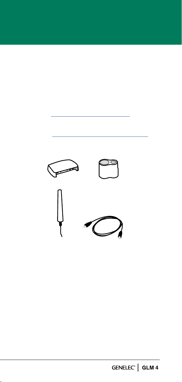
2 PACKAGE CONTENTS
GLM Adapter
Microphone
Microphone holder
USB cable to
computer connection
3 GETTING STARTED
To take full advantage of your Smart Active Monitoring
(SAM) system it is important to become familiar with all
the components in the system. More detailed information can be found from the GLM 4, monitor and subwoofer operation manuals.
To set up a monitoring system you will need monitors
and subwoofers, audio signal cables, GLM control
network cables, GLM network adapter, GLM measurement microphone, and computer with GLM 4 software.
3
Page 4
L R
A
B B
A
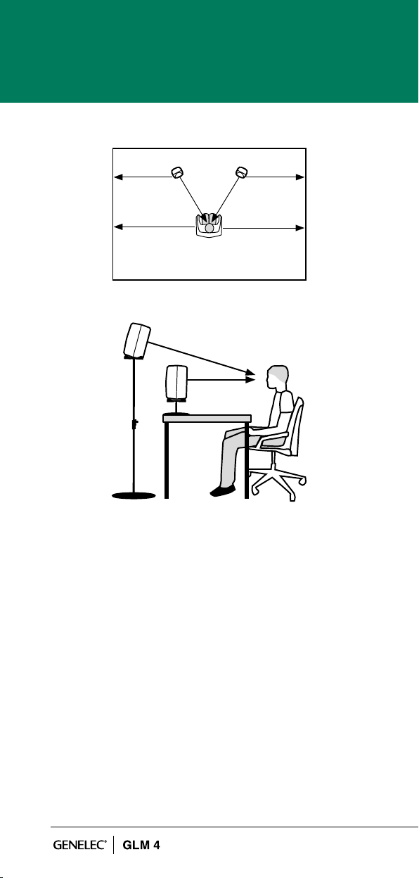
Figure 1. Place monitors symmetrically relative to the walls.
Point the acoustical axes towards the listening position.
To set up a Genelec SAM system
• Check the dip switches of the SAM subwoofers and
monitors. The ‘Stored’ switch need to be turned ON
if storing the settings to the SAM subwoofers and
monitors for standalone use. Other controls are not
active when using the stored settings.
• Place SAM subwoofers and monitors in the moni-
toring room.
• Run audio cables to the SAM subwoofers and
monitors.
4
Page 5

• Run GLM network cables from the GLM adapter to
all SAM subwoofers and monitors.
• Download and install the GLM computer software.
• Create a system setup within the GLM software.
3.1 PLACING MONITORS IN THE MONITORING ROOM
Try to place monitors and subwoofers in optimum locations in relation to surfaces reecting audio, see Figure 1.
Aim each SAM monitor towards the listening position.
This becomes your System Layout. More info about the
correct monitor placement is available at www.genelec.
com/monitor-placement
1. Select listening position so that distances from side
walls (B) are equal.
2. Place monitors so that distances to the listening posi tion are equal, and distances to the monitors are
equal from side walls (A).
3. Place any subwoofers at the front wall, and slightly
left or right from the room centre axis.
4. Aim monitors towards the listening position.
3.2 CABLING FOR AUDIO SIGNALS
Run all audio cables from the audio source to the
monitors. When a subwoofer is used, run the same
signal to the monitor and the subwoofer. We recommend running the signal to the subwoofer rst. The
subwoofer has output connectors to facilitate onward
connection to the monitors.
Those audio channels that are not going to be bass
managed can be run directly to the monitors and do not
need to run to the subwoofer. Bass management means
using a subwoofer to reproduce the low frequencies for
any or all channels.
When you need both analog and digital audio cabling,
it is possible to populate both analog and digital inputs
and outputs on SAM products. GLM allows Group
conguration to be either analog or digital. Note that
the 8320 features an analog input only.
5
Page 6
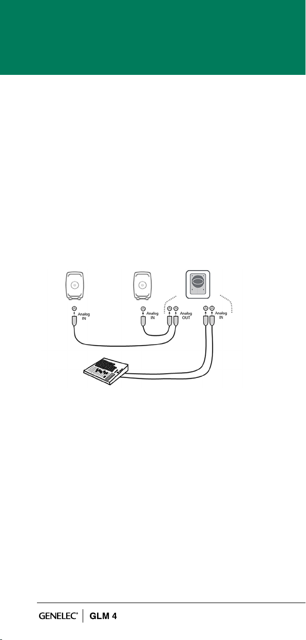
3.3 ANALOG STEREO WITH A SUBWOOFER
Before cabling, turn off the power in all monitors and
subwoofers.
• Connect (Left) audio cable from the source to the
subwoofer connector ANALOG IN 1.
• Connect a cable from subwoofer ANALOG OUT 1
to left monitor ANALOG IN.
• Connect (Right) audio cable from the source to
subwoofer ANALOG IN 2.
• Connect (Right) audio cable from Subwoofer
ANALOG OUT 2 to right monitor ANALOG IN.
Figure 2. Analog stereo cabling with a subwoofer.
3.4 CABLING OF THE CONTROL NETWORK
The GLM control network cabling is very easy. Connect
the GLM adapter to the computer USB port using the
supplied USB cable. Connect the GLM adapter to all
SAM monitors and subwoofers in daisy-chain fashion
(Figure 3) using the network cables supplied with each
monitor and subwoofer. You can connect in any order.
Just be sure to connect all monitors and subwoofers.
6
Page 7
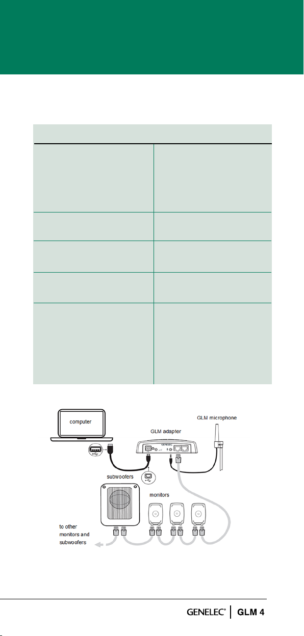
Table 1. Connections on GLM adapter (from left to right).
CONNECTOR USE
USB (type B) Connection for a USB
cable on your computer.
For stand-alone opera-
tion, connection from a
USB power supply.
Volume (3.5 mm jack) Connection for Genelec
volume controller
Microphone (3.5 mm jack) Connection for Genelec
calibration microphone
GLM Net (RJ45) GLM control network
connection
Terminator (RJ45) Return termination for the
GLM control network
from the last monitor, in
case of network cabling
being greater than
100 meters
Figure 3. Connections of GLM control network,
measurement microphone, and computer.
7
Page 8
3.5 DOWNLOADING AND INSTALLING
GLM SOFTWARE
The GLM software calibrates and controls Genelec
SAM systems. The software can be downloaded at
www.genelec.com/glm.
You must have sufcient rights to install the software
in your computer. Install the software following the
instruction given by the software during the installation
process. We recommend you install the software on the
local hard drive. There is no need to make any special
destination folders, GLM creates these automatically.
www.genelec.com/glm
Figure 4. GLM software download
3.6 CREATING SYSTEM LAYOUT AND CALIBRATING
Before launching the GLM software after installation,
stop or mute the audio source, ensure that all monitors
and subwoofers are connected to the GLM network and
are powered on.
The steps to create a GLM System Setup with a system
layout and calibration are
1. Create a SAM monitoring system layout.
2. Dene SAM monitoring group preset.
3. Run GLM AutoCal automatic calibration.
4. Run GLM AutoPhase automatic phase calibration for
subwoofers (AutoPhase is only available when a
subwoofer is included in a group).
5. Run GLM WooferCal automatic calibration for woofer
8
Page 9

system (WooferCal is only available when an adaptive
woofer system is included in a group).
For additional groups, repeat steps 2 - 5.
3.7 CREATING SAM MONITOR LAYOUT
To create a layout all monitors, subwoofers and woofer
systems must be powered and GLM network connections must be made.
A layout denes your monitors and their locations in the
room. Place Left and Right monitor pairs symmetrically
to the grid to be able to use the automatic symmetrical
room response calibration. Figure 5 shows a stereo
system with a subwoofer.
A new system layout is created when the GLM user
interface starts the rst time. You can always create
a new layout by selecting the ‘File | New’ menu item.
When the creation of a new layout starts, initially all
monitors, subwoofers and woofer systems are stacked
on the left side of the page.
1. The layout style selection – shows example positions
for each system (example positions can be skipped
e.g. subwoofer can be placed between Left and
Right monitors).
2. The devices – the UnPlaced device cell on the right
and the Not Used device cell on the left. Start to drag
the device icon from the UnPlaced device cell and
the device will play the ID tone. Place the device
icon to the Layout grid (3) to the position that matches
its placement in your monitoring system layout.
3. The Not Used device cell. This will be used e.g. with
the SE System where GLM needs to know the
unused channels.
4. The layout grid – the monitoring system layout style
with the Stereo with subwoofer system. The center
cell is the listening position (will be placed with the
VOG monitor in an Auro3D system). The top cells
of the grid are the front monitors and the bottom
cells are the rear monitors.
9
Page 10

5. The monitor already placed to the layout grid.
6. The layout conrmation button – Click to proceed
after the layout matches the actual monitoring
system layout.
7. The setup process indicator – AutoPhase will be
skipped if there is no any subwoofers in use and
WooferCal will be skipped if there is no any Woofer
systems in use.
7
1
2
3
4
5
6
Figure 5. Drag and drop the monitor icons onto the layout
grid to build a system layout.
3.8 CREATING GROUP PRESET
A group preset is a set of monitors and subwoofers
that reproduce audio together. A group preset contains
input and acoustic settings to optimize all monitors and
subwoofers active within the group. More group presets
can be created to fullll any need e.g. calibrate system
to the another listening position.
To dene a monitoring group:
1. Give the group a name that describes it (e.g. Analog
Stereo).
2. Optionally you can set the System delay. It will be
applied to all monitors and subwoofers in the group.
10
Page 11
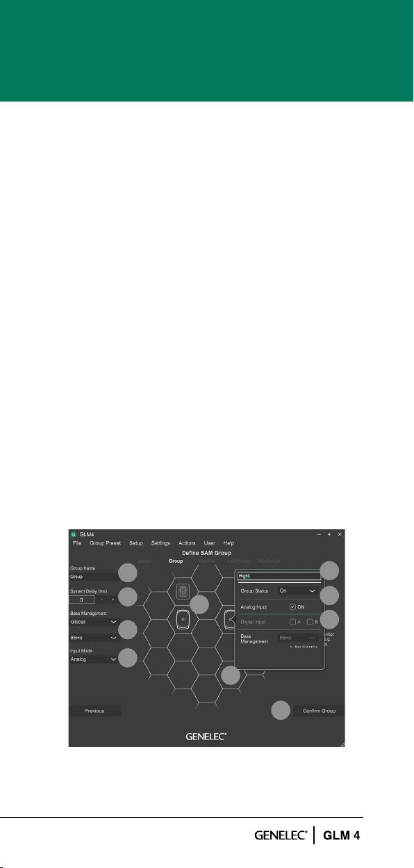
3. Select and check the bass management crossover
frequency required. This setting can be a global if
all monitors are to follow the crossover selected.
If the setting is an individual, then crossover
selections will be done individually for each
monitors via a settings popup.
4. Select the Input mode (Digital channel can be
changed from the Settings popup by clicking a
monitor icon).
5. Settings popup will appear when the monitor icon
is clicked.
6. Name the monitor.
7. Make a monitor active or inactive within the group
(inactive monitors are indicated by a light gray colour).
8. Select an input.
9. Select active monitors. A light icon indicates inactive
monitors within the group state (these will be hidden
in other pages). A normal icon indicates active
monitors within the group state.
Conrm the group settings by clicking on the
10.
‘Conrm Group’ button.
For more detailed information on using and setting up
Groups, see the section ‘GLM Advanced Use’.
1
2
9
3
4
5
Figure 6. Steps to create a group setting.
6
7
8
10
11
Page 12

3.9 AUTOMATIC CALIBRATION
GLM AutoCal is a powerful monitoring system calibration
algorithm running in the Genelec Cloud. Sweeps are
generated by each monitor in a group. Responses are
recorded with the GLM measurement microphone into
your computer.
NOTE: Adaptive Woofer Systems will be calibrated in
the WooferCal page after the AutoCal and AutoPhase
stages.
The algorithm analyzes the sweeps and calculates the
frequency responses for all monitors and subwoofers,
then optimizes level and delay to compensate for
differences between monitors. It also sets equalization
for the individual room responses to remove colorations
caused by the room and the location where the monitors
have been installed. The end result is to have sound from
all monitors arriving at the listening position at the same
time, same level, and compensated for the effects of the
room acoustics, resulting in very accurate
imaging and reliable monitoring.
Each monitor group has its own acoustic settings.
This is one of the important features of GLM.
Each setup le can contain several monitoring group
preset denitions each with different AutoCal calibration
settings.
Even with the same set of monitors you can determine
several listening positions by applying calibration in
several locations and dening each location as a new
group preset. For example, one group can be ‘Engineer
Position’ and another ‘Producer Position’. Each can
have its own calibration. Then, by selecting the group in
the GLM software, it quickly loads all acoustic settings
specic for each microphone position.
12
Page 13

To calibrate a monitoring group
1. Check the serial number of the measurement micro-
phone (measurement microphone calibration le is
retrieved during rst calibration)
2. Select the calibration mode; either a single location
measurement (SinglePoint) or measurements of
multiple measurement positions (MultiPoint). Select
the Symmetrical EQ if a Left/Right pair of monitors
should receive the same calibration lters. The
Individual EQ would be useful for unsymmetrical
setups where one monitor is in a corner and the other
free-standing. In order for the symmetric lters func
tion to be used, monitors need to be symmetrical on
the grid. Monitor pairs not positioned symmetrically
on the grid will be handled as individual units.
3. Connect the measurement microphone to the GLM
network adapter, place the microphone at the listen
ing position, at ear height, and click on the ‘Start
Calibration’ button to start the measurement and
follow the dialog instructions.
- All monitors and subwoofers will be measured,
and if MultiPoint is selected then next position(s)
will be measured.
- Optimization starts.
- Wait until optimization nishes.
- The calibration results can be viewed by clicking
any loudspeaker icon.
4. Click ‘Conrm Calibration’ button to accept and save
the settings to the setup le.
If there is a subwoofer in the group, the next step of
the process is the automatic adjustment of the phase
(AutoPhase).
13
Page 14

1
2
3
4
Figure 7. Steps in running the AutoCal automatic system
calibration process.
3.10 ALIGNING SUBWOOFER PHASE
The purpose of GLM AutoPhase is to set the subwoofer
phase at the crossover frequency, in relation to a selected
monitor, so that the combined response of the subwoofermonitor system is at across the crossover region. The
steps to run AutoPhase automatic subwoofer phase
calibration include:
1. Dene the monitor to be aligned with the subwoofer
by single clicking on the subwoofer icon rst and
then the monitor icon; this is done for each sub-
woofer in the group; if there are several subwoofers
in the group, associate every subwoofer with a moni tor before proceeding to the AutoPhase calibration.
The ‘Pair’ text with number will show the paired sub
woofer and monitor.
2. Connect the calibration microphone to the GLM
adapter, place the microphone at the listening
position, at ear height, and start the AutoPhase
measurement process by clicking on the ‘Start
Calibration’ button. Wait until the AutoPhase
calibration is completed.
14
Page 15

3. Click the ‘Conrm Calibration’ button to accept and
save the calibration to the setup le. If there are
several subwoofers in the group, the AutoPhase
will move to the next subwoofer automatically.
1
1
2
3
Figure 8. Steps in running the AutoPhase automatic phase
calibration process.
3.11 WOOFER SYSTEM CALIBRATION
For a system containing Adaptive Woofer Systems, the
rst part of the calibration (calibrating the main monitor)
is the same as that shown in the Automatic Calibration
section (3.9). Once that process has nished (providing
woofer systems are active in the group), you will be
directed to the woofer system calibration page.
1. The rst step is to pair the monitors to the respective
woofer systems. This is done by rst single-clicking on
the woofer system and then single-clicking on the
monitor it should be paired with. This process is
repeated for all woofer system + monitor pairs in the
Group. Once paired, the pairing will continue to other
Groups.
2. Firstly, the calibration mode is selected by using the
drop-down menu – selecting between Complementary,
15
Page 16

Continued directivity, or one of the three directivity null modes.
Each calibration mode or setting will require an individual
group to be created.
3. The parameters for setting the search limits for the crossover
to the main monitor should then be set. These controls are
available for all modes except the Continued directivity mode,
where the crossover value is xed based on the main monitor
connected in the pairing. This crossover has been set to
where the main monitor and woofer system have the closest
matched directivity.
4. Connect the measurement microphone to the GLM network
adapter, place the microphone at the listening position, at ear
height, and Click on the ‘Start Calibration’ button to start the
measurement and follow the dialog instructions.
• All Adaptive Woofer Systems and monitors will be measured.
• Optimization starts.
• Wait until optimization nished.
• The calibration results can be viewed by clicking any
loudspeaker icon.
5. Click ‘Conrm Calibration’ button to accept and save
the calibration to the setup le.
1
2
3
3
4
Figure 9. Adaptive woofer system calibration.
16
5
Page 17

3.12 BASIC USE OF GLM
1. System level.
2. Selection and activation of group presets.
3. Mute, mute all.
4. Dim (-20dB).
5. Standard loudness SPL level (calibration from ‘Group
Preset : Standard Loudness SPL Calibration’ menu).
6. Level preset selections (to set adjust the system level
at desired level and click ‘Group Preset : Set Preset
Levels : Set Current Level to Preset1).
7. Bypass BM, will bypass the Bass Management
crossover lter. Subwoofers will mute and monitors
will play in the full band.
8. The GLM AutoCal status is indicated on the ‘Cali brated’ button. This button also allows temporary
disabling or bypass of the system acoustic cali bration settings, by pressing the ‘Calibrated’ button.
9. Loudspeaker click mode. Select what happens when
the loudspeaker icon (10) is clicked in the main page.
Solo – Clicked loudspeaker will be soloed and others
will be muted. Clicking a muted loudspeaker, it will be
also soloed. Clicking a loudspeaker icon multiple
times will toggle its state. To clear solo state, click
the empty cell or use right click and select ‘Play all’.
- Mute – Clicked loudspeaker will be muted.
- Info – Clicked loudspeaker information popup will
be shown.
- Edit – Clicked loudspeaker acoustic editor will be
shown.
The microphone SPL level, shown if the microphone
10.
is connected.
11.
The SAM subwoofer and monitor icon. Use the
loudspeaker click mode (8) to select what happens
when a loudspeaker is clicked.
12.
Click the ‘Play All’ button to turn off all solo and
mute states.
13.
The currently loaded system setup le and network
status.
17
Page 18

1
13
3
4
5
11
2
6
7
8
9
10
Figure 10. GLM software main page.
12
4 ADVANCED USE OF GLM
GLM is the most powerful tool available to calibrate and
control a Genelec SAM monitoring system. This section
introduces the advanced use of the GLM
4.1 IMPORTING GLM3 SETUP
GLM3 Setup le can be imported to GLM4. Import function will import selected GLM3 setup le. GLM3 setup
le remains untouched and can be still used with GLM3.
NOTE: GLM4 setup le cannot be opened with GLM3.
18
Page 19

Follow these steps:
1. Open GLM4 main page (at least one setup with GLM4
must be created)
2. Click ‘File : Import GLM3 Setup…’ menu.
Figure 11. Import GLM3 Setup-menu.
3. Select a GLM3 setup le to be imported and click
‘Open’.The imported setup will be stored with the
same name to GLM4.
Figure 12. Selecting a setup to be imported from the GLM3
setup folder.
4. The GLM3 le is now imported to GLM4. Settings other
than the layout are all kept the same: acoustic settings,
groups etc. If there is a need to edit the layout, it can be
done by clicking the ‘Setup: Edit Layout’ menu.
19
Page 20

4.2 STANDARD LOUDNESS SPL CALIBRATION
The Standard Loudness SPL feature allows calibration
of the listening level in accordance with digital loudness
standards such as ATSC A/85 and EBU R128. Calibrated
listening level is important to judge speech intelligibility,
spectral balance, platform compatibility etc.
The in-situ frequency response compensation and system alignment should be followed by the absolute SPL
listening level calibration. Note: Digital monitor interfacing
should be used to reduce uncertainty and tolerances.
• Before SPL calibration, rst perform the other cali-
bration functions to compensate frequency response,
time of ight, level difference between channels and
sub phase. You would typically do this by creating
a new “Group”, using the Add Group command; or
by editing an existing “Group”, using the Edit Group
command.
• If you require a frequency response other than at,
for instance an HF roll-off such as x-curve, now make
those adjustments. To edit all channels at once,
consider using the Sound Character Proler. Per
channel, select and edit individual monitors.
• SPL calibration should be the nal item: Click the
‘Group Preset : Standard SPL Calibration’ menu
on the main page. The Standard Loudness SPL
Calibration window opens.
Figure 13. Entering the Standard Loudness SPL
Calibration page.
20
Page 21

• Select level calibration standard from the dropdown list.
• Place the Genelec calibration microphone at the
listening position.
• Click the ‘Start Calibration’ to start the calibration
process. Note that the test signal may be loud. If the
background noise in the room is more than 65 dB SPL,
the loudness preset cannot be calibrated. Reduce the
noise and calibrate again.
Figure 14. The standard loudness SPL calibration.
• After calibration, click the ‘Conrm’ key to save the
results and return to the main page.
After SPL calibration, the main page shows the preset
levels in dB SPL units, and the Level Preset 1 is set at
the standard level, e.g. 73 dB SPL for EBU R128.
(Notice the graphical link-line between the Cal.
Level and Level Preset 1 keys).
To remove the Standard SPL calibration open the
calibration page and select ‘Remove Calibration’
from the Standard list and click the ‘Conrm’ button.
4.3 SOUND CHARACTER PROFILER TOOL
If you feel the overall spectral balance of your system
needs adjustment, i.e. making it generally darker or
21
Page 22

brighter, the Sound Character Proler found in the
Group Preset menu is a quick place to start. There are
Proler Presets including the Manual option. Setting the
Proler uses two shelving lters in all monitors in the
selected Group.
The Sound Character Proler tool (SCP) can be accessed
via the ‘Group Presets | Sound Character Proler’ menu.
Figure 15. Sound Character Proler tool.
4.4 STORING VALUES IN MONITORS AND
SUBWOOFERS
SAM monitors and subwoofers are set up and calibrated
using the GLM control network and the GLM software.
After setup, monitors, subwoofers and the GLM adapter
can also operate without having a computer connected
to the GLM adapter. This is called stand-alone operation.
SAM monitors and subwoofers retain their settings
after storing the settings inside the monitors and
subwoofers. In some models there is a ‘Stored
Controls’ switch, which needs to be turned ON to make
the monitor use the stored settings in stand-alone
mode. The ‘Stored Controls’ switch status can be seen
in the Store Groups Settings page under each monitor
(N/A = monitor has no dip switch).
22
Page 23
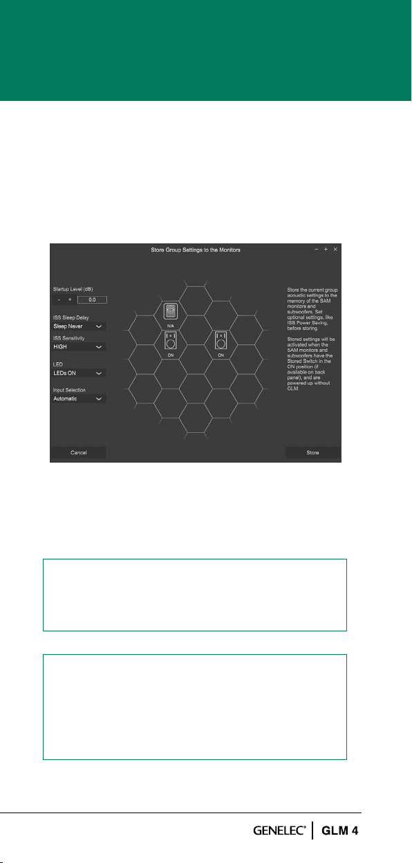
Storing is done with the ‘Group Preset: Store to
Loudspeakers’ menu command.
Settings that are stored; The Current Group Acoustic
Settings, Startup Level, ISS Power Saving settings,
LED Disable and Input Mode.
Figure 16. Store Group Settings page
ISS support is not available for the following
products: 7260A, 7261A, 7270A, 7271A, 8240A,
8250A, 8260A.
LED Disable and Input Mode support are not
available for the following products: 7260A,
7261A, 7270A, 7271A, 8240A, 8250A, 8260A,
8351A, 1238CF, 1237A, 1238A, 1238AC, 1238DF,
1234A, 1234AC, 1236A.
23
Page 24

4.5 STATUS INDICATORS
The top right corner shows the system state: ‘Status:
OK’ (all devices are working normally), ‘Status: LS
Ofine’ (one or more monitors in this group are not
reachable by the network), ‘Status: Adapter Ofine’
(GLM Adapter is not connected to the computer).
The loudspeaker states will be indicated with the
following colours (see gure below).
• The loudspeaker icon without any added colour
indicates the normal state.
• The loudspeaker icon with the black background
indicates the loudspeaker is ofine.
• The loudspeaker icon with the red background
indicates the loudspeaker is clipping.
• The loudspeaker icon with the yellow background
indicates the loudspeaker has protection ON.
• The red border of the loudspeaker cell tells that the
loudspeaker is muted.
• The green border of the loudspeaker cell tells that
the loudspeaker is soloed.
Figure 17. GLM status indicators.
24
Page 25

4.6 CLOUD ACCOUNT
GLM’s Cloud version requires the user to have an
account in the Genelec Community. This can be created
at www.community.genelec.com. With a valid user
account, log in is then possible from the ‘User:Login’ menu.
Log in To log in to the Genelec Cloud, enter a valid user
name and password on the Genelec Community page.
Figure 18. Login to Genelec Community window.
User information / Logout. To logout from the GLM
Cloud, click the Logout from User menu.
5 MORE DETAILED INFORMATION
More detailed information is available on the Genelec
website and in the individual GLM, monitor and
subwoofer operation manuals.
Please visit the GLM product page to download the
GLM Operating Manual with detailed information about
GLM software www.genelec.com/glm
The SAM studio monitors and subwoofers page at
www.genelec.com/sam-studio-monitors-subwoofers
enables you to download a detailed Operating Manual
for each SAM model, with measurements and detailed
monitor performance specications.
25
Page 26

6 SAFETY CONSIDERATIONS
All SAM monitor systems have been designed in
accordance with international safety standards. The
following warnings and cautions must be observed
to ensure safe operating conditions:
• Servicing and adjustment may only be performed by
qualied service personnel.
• The monitor/subwoofer must not be opened.
• Do not expose the monitor/subwoofer to water or
moisture.
• Do not place objects lled with liquid, such as vases,
on the monitor/subwoofer or near it.
• The monitor/subwoofer alone can produce sound
pressure levels in excess of 85 dB, which may cause
permanent hearing damage.
• Free ow of air behind the monitor/subwoofer is
necessary to maintain sufcient cooling. Do not
obstruct the airow around the monitor/subwoofer.
• The monitor is not disconnected from the power supply
unless the mains cable is removed from the monitor/
subwoofer. Powering down the monitor/subwoofer
using its power switch does not disconnect power.
• Ensure that mountings to walls or ceilings for
example are able to carry the full weight of the
monitor/subwoofer in all circumstances, and the
installations have been designed and are implemented
according to the local safety regulations and follow
principles of good workmanship.
• Genelec products and accessories come with
instructions on the proper methods of installation
and use. Please follow these instructions.
26
Page 27

27
Page 28

Factory & Headquarters
Genelec Oy
Olvitie 5
FI-74100 Iisalmi
Finland
T +358 17 83 881
genelec@genelec.com
USA
Genelec Inc.
7 Tech Circle
Natick MA 01760
USA
T +1 508 652 0900
genelec.usa@genelec.com
Sweden
Genelec Sweden
Ellipsvägen 10A
SE-141 75 Kungens Kurva
Sweden
T +46 8 449 5220
sweden@genelec.com
Japan
Genelec Japan Inc
2-22-21 Akasaka
Minato ku
JP-107-0052 Tokyo
Japan
T +81 3 6441 0591
genelec.japan@genelec.com
China
Beijing Genelec Audio
Room 101, Building B33
Universal Business Park
No.10 Jiuxianqiao Road
Chaoyang District
Beijing 100015
China
T +86 10 5823 2014
T +86 400 700 1978
genelec.china@genelec.co
www.genelec.com/glm
Genelec Document D0183R001. Copyright Genelec Oy 12.2020. All data subject to change.
m
 Loading...