

Page 1
7000 Series
Operating Manual
Käyttöohje
Genelec 7050C Active Subwoofer
Page 2

Genelec 7050C Active Subwoofer
General Description
The Genelec 7050C active subwoofer is a
very compact low frequency loudspeaker,
designed to extend the bass reproduction
of Genelec active loudspeakers in stereo
or surround applications. Adding the
7050C to the system creates a compact
neareld monitoring system capable of a at
frequency response down to 24 Hz (-6 dB).
Driver
The 7050C contains a single 205 mm (8
in) magnetically shielded low frequency
driver, housed in a Genelec Laminar Spiral
EnclosureTM (LSETM) bass reex cabinet.
Bass Management Unit
The built-in bass management unit has
ve signal input and output channels and a
discrete LFE signal input.
The active crossover contained in the bass
management unit splits the input signals into
low and high frequency components at 85
Hz. Frequencies below 85 Hz are directed to
the subwoofer and frequencies above 85 Hz
to the main speakers.
The low pass section sensitivity can be
adjusted from +12 dBu to -6 dBu to allow
easy subwoofer level matching with various
main speakers. All outputs have 0 dB
passband gain.
The input sensitivity of the LFE channel
can be set to 0 dB or +10 dB.
Balanced XLR connectors are used for the
system audio inputs and outputs.
Two "Bass Roll-Off" switches are
included to provide a flat bass response
in all acoustical environments, enabling
adjustments of the subwoofer response
in three -4 dB steps. Two phase
matching switches in the crossover allow
compensation for the delay which occurs
if the subwoofer is placed away from the
main speakers, or for other speaker systems
phase behaviour. Four settings are provided
between 0° and -270°.
ISSTM Autostart
The automatic power saving function ISS
(Intelligent Signal Sensing) can be activated
by setting the “ISS” switch on the connector
panel to “ON.” Automatic powering down
to standby mode happens after a certain
time when playback has ended. The
power consumption in standby mode is
typically less than 0.5 watts. Playback will
automatically resume once an input signal is
detected from the source.
There is a slight delay in the automatic
powering up. If this is undesirable, the ISS
function can be disabled by setting the “ISS”
switch on the connector panel to “OFF.” In
this mode, the subwoofer is powered on and
o using the power switch on the connector
panel.
The “ISS SENSITIVITY LOW” switch
lowers the triggering sensitivity of the
ISS function. This can be necessary if the
subwoofer “wakes up” even if there is no
audio signal.
Amplifier
The amplifier produces 130 W of output
power, with very low THD and IM distortion.
Driver overload protection and power-on
signal muting is included in the amplifier
circuitry. The amplifier also incorporates
thermal overload and short circuit protection.
Installation
The subwoofer is supplied with a mains
cable and this operating manual. Once
unpacked inspect the subwoofer to ensure
that it has not been damaged in transport.
If the subwoofer is brought in from a cold
strorage or transport, let it warm completely
to the room temperature before making any
connections. Ensure that both the subwoofer
and the main loudspeakers are switched o
before making any connections.
Audio connections are made with
balanced XLR cables. The 7050C has IN/
OUT connector pairs for ve main channels
and a dedicated LFE input connector
for the LFE channel. Connect the signal
cables from your source to the female XLR
"IN" connectors on the upper connector
row. Next connect XLR cables from the
corresponding "OUT" male XLR connectors
on the lower row to the input connectors of
each main loudspeaker.
Use the "LFE IN" connector for the LFE or
.1 output channel of a 5.1-channel discrete
surround sound source.
Once all connections have been made,
the subwoofer and main loudspeakers are
ready to be powered up.
Positioning In The Room
The placement of the subwoofer in
the room affects the overall frequency
response and sound level of the system
dramatically, as at low frequencies the
effects of the room are strong. Even a
slight change in the subwoofer's location
can make a marked difference in the
frequency balance and often patient and
methodical experimentation and testing
Page 3
LFE IN CONNECTOR
OR
BYPASS SWITCH
CONNECTOR
SERIAL
CONNECTORS
INPUT
7050C ACTIVE SUBWOOFER
NUMBER
www.genelec.com
MADEIN FINLAND
IN
IN 1IN2 IN 3
IN 4IN5
OUT
OUTPUT
OUT1 OUT2 OUT 3 OUT4 OUT 5
CONNECTORS
SENSITIVITY
ADJUSTMENT
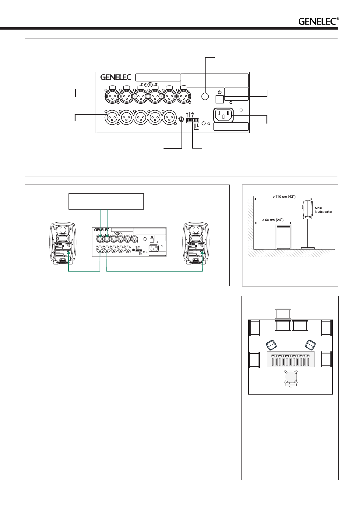
Figure 1. 7050C's amplier panel, connectors and controls.
LINE LEVEL SIGNALSOURCE
WARNING
ELECTRICSHOCKHAZARD. DONOTOPEN.DONOT SUBJECTTOWATEROR MOISTURE.NOUSER
SERVICEABLEPARTSINSIDE.REFERSERVICING TOQUALIFIEDPERSONNEL. USEEARTHED MAINS
CONNECTIONONLY.
AVERTISSEMENT
RISQUEDECHOC ÉLECTRIQUE.NEPASOUVRIR.NE PASEXPOSERÀL'EAUOU L'HUMIDITÉ.AUCUN
COMPOSANTÀL'INTÉRIEURREMPLAÇABLEPARL'UTILISATEUR.ADRESSER TOUTERÉPARATIONÀ
UNPERSONNELQUALIFIÉ. CETAPPAREILDOITÊTRERACCORDÉÀLATERRE.
BYPASS
LFEIN
ROLL-OFF PHASE
-270°
-8dB
-90°
-4dB
-180°
0
+3
-3
+6
-4
ON
+12
-6
THISDEVICECOMPLIESWITHFCC PART15AND
ISS
ISSSENSITVITYLOW
LFE+10dB
CANADIANICES-003RADIO FREQUENCYCLASSB
EMISSIONREQUIREMENTS.REFER TOOPERATING
MANUALFORFULLINFORMATION.
INPUTdBu
PRODUCING
100dB SPL(1m)
LAITEONLIITETTÄVÄ
SUOJAKOSKETTIMILLA
VARUSTETTUUNPISTORASIAAN.
APPARATETMÅTILKOPLES
JORDETSTIKKONTAKT.
APPARATENSKALLANSLUTAS
TILLJORDATUTTAG.
MAINSINPUT
50/60Hz 150W
100-240V~
ALLOFF
0
-2
-4
-6
BASS
ROLL-OFF
MAINSINPUT
50/60Hz60W
ThisdevicecomplieswithFCCPart15andCanadian
ICES-003radiofrequencyClassBemissionrequirements.
Refertooperatingmanualforfullinformation.
100-240V~
DESKTOP
16020 20k
Frequency(Hz)
WARNING:ELECTRICSHOCKHAZARD.DONOTOPEN.DONOT
SUBJECTTOWATERORMOISTURE.NOUSERSERVICEABLE
PARTSINSIDE.REFERSERVICINGTOQUALIFIEDPERSONNEL.
USEEARTHEDMAINSCONNECTIONONLY.
AVERTISSEMENT:RISQUEDECHOCÉLECTRIQUE.NEPAS
OUVRIR.NEPASEXPOSERÀL'EAUOUL'HUMIDITÉ.AUCUN
COMPOSANTÀL'INTÉRIEURREMPLAÇABLEPARL'UTILISATEUR.
ADRESSERTOUTERÉPARATIONÀUNPERSONNELQUALIFIÉ.
CETAPPAREILDOITÊTRERACCORDÉÀLATERRE.
LAITEONLIITETTÄVÄSUOJAKOSKETTIMILLAVARUSTETTUUN
PISTORASIAAN.
APPARATETMÅTILKOPLESJORDETSTIKKONTAKT.
APPARATENSKALLANSLUTASTILLJORDATUTTAG.
BASS
TILT
TREBLE
TILT
3k
1k
8030CBI-AMPLIFIED
MONITORINGSYSTEM
MADEINFINLAND
SERIALNUMBER
SERIAL
NUMBER
7050CACTIVE SUBWOOFER
292-8030W
ON
OFF
-6
+6
ISS
-3
-2dB
-4dB
+4
0
+2
INPUTdBu
PRODUCING
100dBSPL(1m)
TREBLETILT-2dB
BASSTILT
BASSROLL-OFF-4dB
DESKTOP160Hz-4dB
ANALOG
IN
231
www.genelec.com
-
GND
+
IN
292-8030CT
IN
IN1IN2 IN3
OUT
OUT1 OUT2 OUT 3 OUT 4 OUT 5
www.genelec.com
MADEINFINLAND
IN4IN5
-270°
-90°
-180°
ISS
ISSSENSITVITY LOW
LFE+10 dB
WARNING
AVERTISSEMENT
BYPASS
ON
THISDEVICE COMPLIESWITHFCC PART15 AND
CANADIANICES-003 RADIO FREQUENCYCLASS B
EMISSIONREQUIREMENTS. REFER TOOPERATING
MANUALFORFULLINFORMATION.
LAITEONLIITETTÄVÄ
SUOJAKOSKETTIMILLA
VARUSTETTUUNPISTORASIAAN.
APPARATETMÅ TILKOPLES
JORDETSTIKKONTAKT.
APPARATENSKALL ANSLUTAS
TILLJORDAT UTTAG.
ELECTRICSHOCK HAZARD. DONOTOPEN.DO NOTSUBJECT TO WATEROR MOISTURE.NO USER
SERVICEABLEPA RTSINSIDE. REFERSERVICING TOQUALIFIED PERSONNEL. USE EARTHEDMAINS
CONNECTIONONLY.
RISQUEDE CHOC ÉLECTRIQUE.NE PASOUVRIR.NE PASEXPOSER ÀL'EAUOU L'HUMIDITÉ.AUCUN
COMPOSANTÀL'INTÉRIEURREMPLAÇABLEPARL'UTILISATEUR. ADRESSERTOUTE RÉPARATIONÀ
UNPERSONNEL QUALIFIÉ. CETAPPAREILDOITÊTRE RACCORDÉÀLATERRE.
LFE IN
ROLL-OFF PHASE
-8dB
-4dB
0
+3
-3
+6
-4
+12
-6
INPUTdBu
PRODUCING
100 dBSPL (1 m)
BASS ROLL-OFF,
ISS AND LFE +10 dB
WARNING:ELECTRICSHOCKHAZARD.DONOTOPEN.DONOT
SUBJECTTOWATERORMOISTURE.NOUSERSERVICEABLE
PARTSINSIDE.REFERSERVICINGTOQUALIFIEDPERSONNEL.
USEEARTHEDMAINSCONNECTIONONLY.
AVERTISSEMENT:RISQUEDECHOCÉLECTRIQUE.NEPAS
OUVRIR.NEPASEXPOSERÀL'EAUOUL'HUMIDITÉ.AUCUN
COMPOSANTÀL'INTÉRIEURREMPLAÇABLEPARL'UTILISATEUR.
ADRESSERTOUTERÉPARATIONÀUNPERSONNELQUALIFIÉ.
CETAPPAREILDOITÊTRERACCORDÉÀLATERRE.
LAITEONLIITETTÄVÄSUOJAKOSKETTIMILLAVARUSTETTUUN
PISTORASIAAN.
APPARATETMÅTILKOPLESJORDETSTIKKONTAKT.
292-8030W
APPARATENSKALLANSLUTASTILLJORDATUTTAG.
ON
OFF
-6
+6
ALLOFF
0
-2
ISS
-3
BASS
-4
-2dB
-4dB
+4
TILT
TREBLE
-6
0
TILT
DESKTOP
+2
BASS
INPUTdBu
ROLL-OFF
PRODUCING
16020 20k
3k
1k
100dBSPL(1m)
Frequency(Hz)
TREBLETILT-2dB
BASSTILT
BASSROLL-OFF-4dB
DESKTOP160Hz-4dB
MAINSINPUT
ANALOG
8030CBI-AMPLIFIED
50/60Hz60W
IN
100-240V~
MONITORINGSYSTEM
231
www.genelec.com
MADEINFINLAND
SERIALNUMBER
-
GND
+
IN
ThisdevicecomplieswithFCCPart15andCanadian
ICES-003radiofrequencyClassBemissionrequirements.
292-8030CT
Refertooperatingmanualforfullinformation.
MAINS INPUT
50/60Hz 150 W
100-240 V~
MAINS SWITCH
MAINS CONNECT
PHASE,
SWITCHES
Figure 2. Audio cable routing example with a two channel source shown.
is needed to nd the optimum placement.
The placement will affect the phase
dierence between the main loudspeakers
frequencies and may cause asymmetrical
spatial imaging.
and the subwoofer and the bass roll-o
rate.
First place the subwoofer slightly oset
from the center of the front wall. The
recommended distance to the wall is
less than 60 cm / 24" measured from the
subwoofer's driver. This position gives
increased acoustic loading (and SPL) due
to the proximity of the front wall and oor.
Cancellations from the front wall and oor
are also avoided. Front wall cancellation for
the 85 Hz high pass ltered main speakers
can be eliminated by placing them at least
110 cm / 43" away from the front wall (see
Figure 3).
If the frequency balance does not seem
Minimum Clearances To Walls
Or Other Objects
Do not cover the driver side of the subwoofer
or place the subwoofer so that there is less
than 10 cm (4") of free space in front of the
grille.
Make sure that the space underneath the
subwoofer is clear from obstructions. Thick
carpets may block the ventilation clearance
needed for cooling the electronics.
The reflex port side (opposite of the
connector panel side) should always have a
clearance of at least 7.5 centimeters (3") to
any objects to ensure proper functioning of
the reex port.
right, try moving the subwoofer slightly
to the left or right so that dierent room
modes are excited at different levels.
Positioning the subwoofer close to a
corner will boost the bass level at lower
Flush Mounting The
Subwoofer
If the subwoofer is flush mounted into a
wall or a cabinet, it is important to ensure
Figure 3. Recommended distances to
the front wall
5
2
3
1
4
Figure 4. Examples of subwoofer posi-
tioning. 1 and 2 are good starting posi-
tions for a single subwoofer and also
work well with two linked subwoofers.
Position 3 causes a signicant bass
boost and may cause asymmetric spa-
tial imaging if only one subwoofer is
used. Position 4 also works best with
two subwoofers. Flush mounting (pos.
5) generally works well.
3
4
Page 4
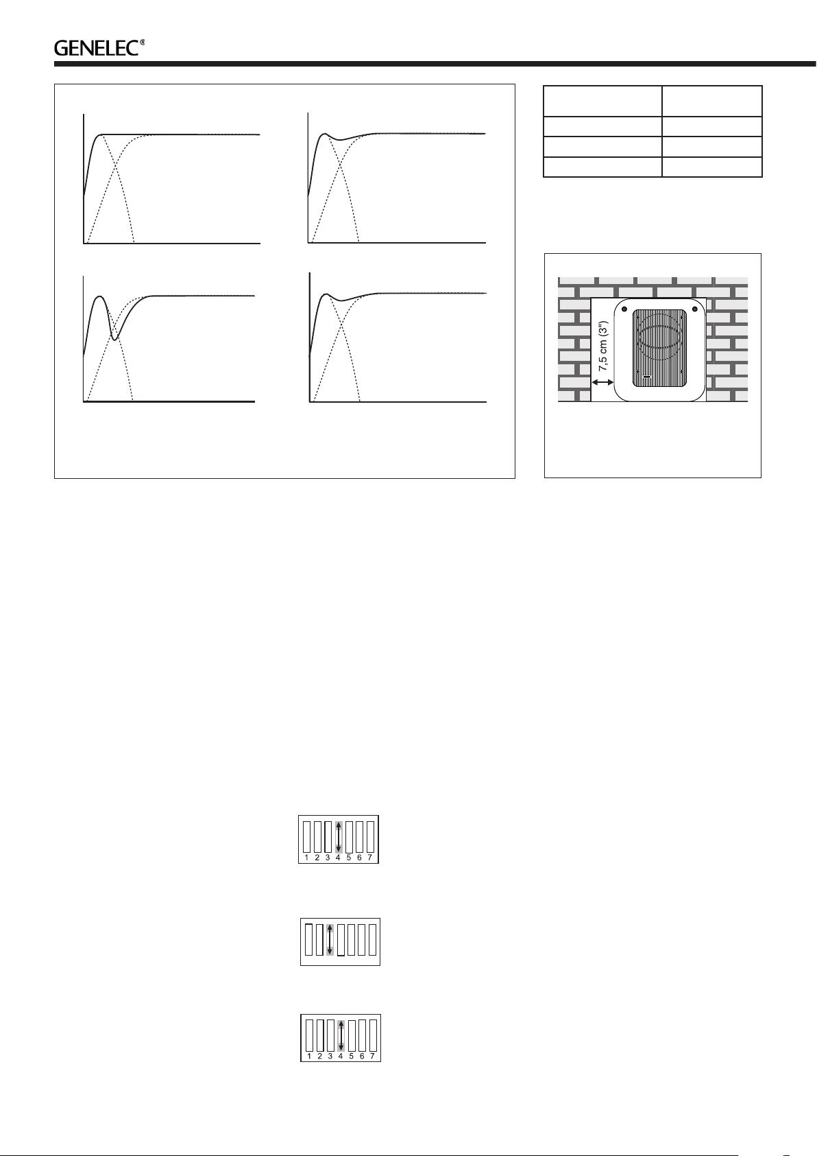
Phase Difference: 0°
Phase Difference: 270°
Phase Difference: 90°
Subwoofer placement Bass Roll-Off
setting
Near to a wall -4 dB
In a corner -8 dB
Flush mounted -4 dB
Table 1. Suggested Bass Roll-O
settings
85 Hz
Phase Difference: 180°
85 Hz
Figure 5. The eect of phase dierence between the subwoofer and the main loud-
speakers
amplifier cooling and unrestricted airflow
from the reex port. This can be done by
making the recess 7.5 centimeters (3") wider
than the subwoofer. Place the subwoofer
into the right end of the recess with the
driver side facing the room. This leaves
sucient 7.5 centimeters (3") of free space
on the reex port side. The height and depth
of the recess should not be any bigger than
is needed to t the subwoofer ush with the
wall surface.
Sensitivity Adjustment
The subwoofer requires input sensitivity
alignment to the source to obtain a
correctly balanced system. The input
sensitivity control is located on the
connector panel of the subwoofer. An
input voltage of -6 dBu with a -6 dBu input
sensitivity setting will produce 100 dB SPL
@ 1 m in free eld.
Setting The Phase Control
Incorrect phase alignment between the
main loudspeakers and subwoofer causes
a drop in the frequency response of the
whole system at the crossover frequency.
The graphs above (Fig. 5) show the eect
of phase difference to the frequency
response.
The phase dierence between the main
loudspeakers and subwoofer at the listening
position is dependent upon the position of
the subwoofer, so the phase adjustment
should be done only after the preferred
85 Hz
85 Hz
position is found. Acoustic measuring
equipment is required for accurate system
alignment. If this equipment is not available,
the following coarse phase matching can
be applied.
Coarse Phase Adjustment
Method
Connect an audio frequency signal generator
to one of the inputs of the 7050C and set
it to feed a 85 Hz signal to the system.
Alternatively, you can use a 85 Hz signal
fom a suitable audio test recording. Make
sure you connect (even temporarily) a main
loudspeaker to the corresponding output
on the subwoofer, so that the test signal is
properly reproduced by both subwoofer and
main loudspeaker.
Toggle the -180° phase
switch (DIP 4 from left)
"ON" and "OFF", and set it
to the position which gives
the lowest sound level at the listening position.
Next toggle the -90°
phase switch (DIP 3) "ON"
4321 765
gives the lowest sound level.
and "OFF", and again set
it to the position which
Finally, set the -180°
phase switch (DIP 4) to
the opposite setting and
deactivate the test signal.
Figure 6. Flush mounting the
subwoofer. Note the clearance needed
on the reex port side.
Phase Correction Method
With Test Equipment
The following procedure matches the phase
between the subwoofer and the main
loudspeakers using a frequency analyser
and a pink noise generator. Connect a
high grade measuring microphone to the
analyser and feed pink noise into one of
the inputs of the subwoofer. Position the
microphone at the listening position and
adjust the input sensitivity of the subwoofer
until frequencies below and above 85 Hz are
reproduced at equal level. Then adjust the
phase control switches for the maximum
dip of at least -6 dB at the crossover
frequency (85 Hz).
Change the -180° switch to the opposite
setting. The phase should now be set
correctly and the frequency analyser should
show a smooth response around 85 Hz.
Using The LFE +10 dB
Function
The LFE channel is usually recorded 10 dB
lower than the main channels so that there
is 10 dB of extra level (headroom) available.
Most AV processors automatically add 10
dB to the LFE channel to restore the level in
the LFE channel but some medium format
mixing consoles and many smaller consoles
do not have the facility to apply the +10 dB
gain to the LFE. To overcome this limitation
Genelec subwoofers provide a +10 dB LFE
gain selection.
Page 5
The “LFE +10 dB” function should not be
dB SPL
used in the following cases:
• If the +10 dB LFE gain is already
implemented by another device, for
example, a surround sound processor or
the output matrix of a mixing console.
• When producing an audio format that
does not require the use of +10 dB gain
on the LFE channel.
Bypass
The Bypass input accepts a 6.3 mm tip-ringsleeve (TRS) or tip-sleeve (TS) plug. This
plug supports a contact open/close switch
device. Connecting the TIP to the SLEEVE
activates the bass management bypass.
When the bass management bypass is
active, the subwoofer only reproduces the
LFE signal and the outputs bypassed to the
monitors are exact copies of the inputs.
Safety Considerations
Genelec 7050C subwoofer has been
designed in accordance with international
safety standards. However, to ensure safe
operation and maintain the unit in safe
operating condition, the following warnings
and cautions must be observed:
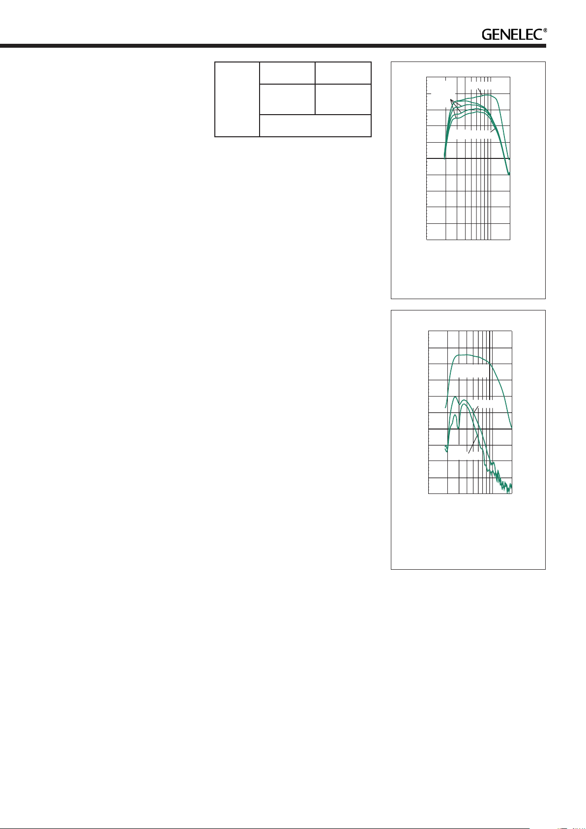
7050C
2 channel
system
8020
8030
M030
Room volume up to
75 m3 / 2647 ft
5 channel
system
8010
8020
3
Table 2. Recommended main speaker
models for the 7050C
Maintenance
No user serviceable parts are inside the
subwoofer. Any maintenance of the unit
must only be performed by qualied service
personnel.
Guarantee
This product is supplied with a two year
guarantee against manufacturing faults or
defects that might alter the performance of
the unit. Refer to supplier for full sales and
guarantee terms.
Compliance to FCC Rules
This device complies with part 15 of the FCC
Rules. Operation is subject to the following
two conditions:
Level vs Freq (Hz) 7050C 4.2.18
+100
+80
dB SPL
+60
+40
+20
+0
10
Bass
Roll-Off
-4,-8 and
-12dB
20
LFE channel
Main channels
50
30
100
200
Hz
Figure 7. The free eld frequency
response of the 7050C subwoofer at
dierent Bass Roll-O settings
Harmonicdistortion 7050C 4.2.18
+100
+80
+60
Fundamental
frequency
2nd harmonic
• Servicing and adjustment must only be
performed by qualied service
personnel. The subwoofer cabinet or
electronics unit must not be opened.
• Do not use this subwoofer with an
unearthed mains cable or an unearthed
mains connection as this may
compromise electrical safety.
• Do not expose the subwoofer to water
or moisture. Do not place any objects
lled with liquid, such as vases on the
subwoofer or near it.
• This subwoofer is capable of producing
sound pressure levels in excess of
85 dB, which may cause permanent
hearing damage.
• Free ow of air around the subwoofer is
necessary to maintain sucient cooling.
Do not obstruct airow around the
subwoofer.
• Note that the subwoofer is not
completely disconnected from the
AC mains service unless the mains
power cord is removed from the
subwoofer or the mains outlet.
Warning!
This subwoofer is capable of delivering sound
pressure levels in excess of 85 dB, which
may cause permanent hearing damage.
• This device may not cause harmful
interference, and
• This device must accept any interference
received, including interference that may
cause undesired operation.
Note: This equipment has been tested and
found to comply with the limits for a Class B
digital device, pursuant to part 15 of the FCC
Rules. These limits are designed to provide
reasonable protection against harmful
interference in a residential installation.
This equipment generates, uses and can
radiate radio frequency energy and, if not
installed and used in accordance with the
instructions, may cause harmful interference
to radio communications. However, there
is no guarantee that interference will not
occur in a particular installation. If this
equipment does cause harmful interference
to radio or television reception, which can
be determined by turning the equipment
o and on, the user is encouraged to try to
correct the interference by one or more of
the following measures:
• Reorient or relocate the receiving
antenna.
• Increase the separation between the
equipment and receiver.
• Connect the equipment into an outlet on
+40
+20
+0
3rd harmonic
10
30
20
50
100
200
Hz
Figure 8. The curves above show the
harmonic distortion analysis of the
7050C in free eld. In half space the
SPL will be 6 dB higher.
a circuit dierent from that to which the
receiver is connected.
• Consult the dealer or an experienced
radio/TV technician for help.
Modications not expressly approved by the
manufacturer could void the user’s authority
to operate the equipment under FCC rules.
Page 6

For each analogue input
enclosure
driver and
Subwoofer
Power
amplifier
protection
Infrasound
features
Overload
protection
-4 dB
-8 dB
Roll-Off
0°
90°
180°
Phase
Sensitivity
alignment
-6…+12 dB
DIP-switches
+
270°
out 1-5
Analogue
LFE
+10 dB
85 Hz
lowpass
Crossover
85 Hz
Highpass
Sum
Subwoofer in
Bypass
Subwoofer in
Analogue
in 1-5
LFE in
120 Hz
lowpass
Crossover
Figure 9. Signal path block diagram of the 7050C.
Page 7

7050C
Lower cut-o frequency (-6 dB) 24 Hz
Upper cut-o frequency (-6 dB)
Main channels / LFE
Driver, magnetically shielded 205 mm (8 in)
Harmonic distortion at 90 dB SPL
at 1 m on axis in half space 30…85 Hz
2nd
3rd
Maximum short term sine wave SPL
output averaged from 30 to 85 Hz,
measured in half space at 1 meter
Self generated noise level in half space
at 1 m on axis (A-weighted)
Weight 17.3 kg (38.1 lb)
Dimensions
Height
Width
Depth
AMPLIFIER SECTION
Amplier short term output power
(Long term output power is limited by
driver unit protection circuitry)
Amplier system THD at nominal output ≤ 0.05 %
Mains voltage 100 - 240 V 50/60 Hz
Power consumption (average)
Standby (ISS active)
Idle
Full output
85 Hz / 120 Hz
≤ 4 %
≤ 1 %
103 dB
≤ 5 dB
410 mm (16 1/8 in)
350 mm (13 3/4 in)
319 mm (12 9/16 in)
7050C
130 W
universal
≤ 0.5 W
11 W
150 W
CROSSOVER SECTIONSYSTEM SPECIFICATIONS
7050C
Subsonic lter (18 dB/octave) below 24 Hz
Input channels 5 + LFE
Low pass frequency for inputs 1-5 85 Hz
Low pass frequency for LFE IN input 120 Hz
Input connectors XLR female
pin 1
pin 2
pin 3
Input impedance 10 kOhm balanced
Midband rejection >400 Hz ≥ 50 dB
High pass frequency for outputs 1-5 85 Hz
Output connectors XLR male
pin 1
pin 2
pin 3
Output gain 0 dB
Bass Roll-O control in 4 dB steps 0 to -12 dB @ 26 Hz
Phase matching control in 90° steps 0 to -270°
Input sensitivity control +12 to -6 dBu
LFE input sensitivity control 0 or +10 dB selectable
gnd
+
-
gnd
+
-
Page 8

Genelec 7050C Aktiivisubwoofer
Yleistä
Genelec 7050C on erittäin kompakti aktiivisubwoofer ja tarkoitettu äänentoistojärjestelmien bassotoiston laajentamiseen sekä
ammatti- että kotikäytössä. Sen toisto ulottuu 24 hertsiin (-6 dB).
Rakenne
7050C:ssä on yksi 205 mm (8")
magneettisuojattu bassoelementti Genelecin
patentoidussa Laminar Spiral EnclosureTM
(LSETM) bassoreeksikotelossa.
Bassonhallinta
7050C:ssä on viisi ottoliitäntää (IN 1-5)
linjatasoisille analogisille audiosignaaleille ja
niitä vastaavat viisi antoliitäntää (OUT 1-5)
pääkaiuttimille. Lisäksi subwooferissa on
erllinen ottoliitin LFE-signaalille.
Subwooferin sisäänrakennettu
bassonhallinta jakaa viiden pääkanavan
signaalin kahtia 85 hertsin taajuudelta. Alle
85 hertsin taajuudet jäävät subwooferin
toistettavaksi ja yli 85 hertsin taajuudet
subwoofer lähettää kunkin pääkaiuttimen
toistettaviksi antoliitäntöjensä (OUT) kautta.
Subwoofetin ottoliitäntöjen herkkyyttä
voidaan säätää +12 ja -6 dBu:n välillä.
Näin subwoofer voidaan sovittaa yhteen
erilaisten pääkaiuttimien kanssa. Kaikkien
antoliitäntöjen päästökaistan vahvistus on
0 dB.
LFE-kanavan ottoliitännän herkkyydeksi
voidaan valita 0 tai +10 dB.
Kaikki audioliitännät on toteutettu
symmetrisillä XLR-liittimillä.
Kahden "BASS ROLL-OFF"-kytkimen
avulla voidaan subwooferin toistoa
alarajataajuuden alueella vaimentaa 4
desibelin portain -12 desibeliin saakka. Kaksi
vaiheensäätökytkintä (PHASE) mahdollistaa
subwooferin vaiheen säädön 90 asteen
välein (0...-270°). Vaiheen säätö voi olla
tarpeen, jos subwoofer ja pääkaiuttimet on
sijoitettu eri etäisyyksille kuuntelupisteestä.
ISSTM Autostart
7050C on varustettu automaattisella,
signaalin tunnistavalla virrankytkennällä
(ISS), joka aktivoidaan kääntämällä
"ISS"-katkaisin asentoon "ON." Tällöin
subwooferin automaattinen, signaalin
tunnistava virrankytkentä kytkee sen
toimintaan heti kun ottoliittimiin tulee
äänisignaali. Vastaavasti subwoofer menee
automaattisesti valmiustilaan, kun on
kulunut jonkin aikaa signaalin päättymisestä.
Valmiustilassa subwooferin tehonkulutus on
alle 0,5 W.
Subwooferin käynnistymisessä
valmiustilasta on pieni viive. Jos tämä ei
ole hyväksyttävää, ISS-toiminto voidaan
deaktivoida kääntämällä "ISS"-kytkin
asentoon "OFF." Tällöin subwooferin
käynnistys ja sammuttaminen tehdään
liitinpaneelissa olevalla painikkeella.
“ISS SENSITIVITY LOW” -katkaisin
alentaa ISS-toiminnon reagointiherkkyyttä.
Tämän toiminnon käyttö voi olla tarpeen,
jos subwoofer käynnistyy aiheettomasti
erilaisista herätteistä, muulloinkin kun ääntä
toistettaessa.
Vahvistin
7050C:n vahvistimen teho on 130 W ja sen
THD- ja IM-särötasot ovat hyvin matalat.
Kaiutinelementin ylikuormitussuojaus,
signaalin mykistys käynnistettäessä sekä
ylikuumenemis- ja oikosulkusuojaus
takaavat laitteen luotettavuuden.
Käyttöönotto
Subwooferin mukana toimitetaan tämä
käyttöohje ja virtajohto. Tarkasta, ettei
subwooferiin ole tullut kolhuja kuljetuksessa.
Jos subwoofer tuodaan sisään kylmästä
varastosta tai kuljetuksesta, sen pitää antaa
lämmetä täysin huoneilman lämpötilaan
ennen kytkentöjen tekemistä. Tarkista, että
kaikki kytkettävät laitteet on sammutettu
ennekuin alat kytkeä niitä yhteen.
Äänisignaalien kytkennässä käytetään
symmetrisiä XLR-liittimiä ja audiokaapeleita.
7050C:ssä on viisi ottoliitäntää (IN 1-5)
linjatasoisille analogisille audiosignaaleille
ja niitä vastaavat viisi antoliitäntää (OUT
1-5) pääkaiuttimille. Lisäksi subwooferissa
on erllinen ottoliitin LFE-signaalille. Kytke
äänilähteeltä tulevat signaalikaapelit
ylemmässä liitinrivissä oleviin XLR "IN"
naarasliittimiin. Seuraavaksi kytke XLRkaapelit alemman rivin "OUT" XLR
urosliittimistä pääkaiuttimiin.
Käytä "LFE IN" -liitintä LFE- tai .1
-kanavan kytkemiseen, jos käyttämässäsi
ääniformaatissa on sellainen.
Kun kaikki liitännät on tehty, subwoofer ja
pääkaiuttimet voidaan käynnistää.
Subwooferin sijoitus
Bassotoiston taso ja tasapaino riippuu
suuressa määrin bassotaajuuksia
tuottavan kaiuttimen sijainnista huoneessa.
Suhteellisen pienikin siirtäminen voi
aiheuttaa merkittävän muutoksen
sointitasapainoon. Subwooferin oikean
paikan etsimiseen kannattaakin paneutua
kärsivällisesti ja huolellisesti, ja jättää
herkkyys- vaiheenkääntö- ja basson tason
säädöt alkuasetuksiinsa, kunnes akustisesti
edullisin sijoitus on löydetty. Sen jälkeen
Page 9

Kuva 1. 7050C:n liitinpaneeli.
MAINS INPUT
50/60Hz 150 W
100-240 V~
7050C ACTIVE SUBWOOFER
SERIAL
NUMBER
OUT
IN
BYPASS
ROLL-OFF PHASE
-270°
-8 dB
-4 dB
ON
ISS
LFE +10dB
-6
0
+3
+12
-3
LFE IN
+6
-4
INPUT dBu
PRODUCING
100 dBSPL (1 m)
ISS SENSITVITYLOW
-90°
-180°
ELECTRIC SHOCKHAZARD. DO NOTOPEN. DONOT SUBJECTTO WATER ORMOISTURE. NO USER
SERVICEABLEPA RTSINSIDE. REFERSERVICING TO QUALIFIEDPERSONNEL. USE EARTHED MAINS
CONNECTION ONLY.
LAITEON LIITETTÄVÄ
SUOJAKOSKETTIMILLA
VARUSTETTUUNPISTORASIAAN.
APPARATETMÅ TILKOPLES
JORDETSTIKKONTAKT.
APPARATENSKALL ANSLUTAS
TILLJORDAT UTTAG.
RISQUE DECHOC ÉLECTRIQUE. NEPASOUVRIR.NE PAS EXPOSER ÀL'EAU OUL'HUMIDITÉ. AUCUN
COMPOSANTÀL'INTÉRIEUR REMPLAÇABLEPARL'UTILISATEUR. ADRESSERTOUTE RÉPARATIONÀ
UN PERSONNELQUALIFIÉ. CETAPPAREILDOITÊTRE RACCORDÉÀLA TERRE.
AVERTISSEMENT
WARNING
IN 1IN2 IN 3
IN 4IN5
OUT1 OUT2 OUT 3 OUT 4 OUT 5
THIS DEVICECOMPLIESWITHFCC PART 15AND
CANADIAN ICES-003RADIO FREQUENCY CLASSB
EMISSION REQUIREMENTS.REFER TO OPERATING
MANUALFORFULLINFORMATION.
MADE INFINLAND
www.genelec.com
HERKKYYDEN
SÄÄTÖ
LFE IN -OTTOLIITIN
ANTOLIITTIMET
BASS ROLL-OFF-,
-KYTKIMET
VAIHE-,
ISS- JA LFE +10 dB
VIRTAJOHDON LIITIN
VIRTAKYTKIN
OTTOLIITTIMET
SUBWOOFERIN OHITUSKYTKIMEN
(BYPASS) LIITIN
LINJATASOINEN ÄÄNILÄHDE
Kuva 2. Audiosignaalin reititys kaksikanavaisessa järjestelmässä.
niitä voidaan käyttää toiston lopulliseen
hienosäätöön.
Hyvä sijoitus löytyy usein etukaiuttimien
takana olevan seinän vierestä, hieman
huoneen keskilinjan sivulta. Subwoofer
kannattaa pitää lähellä seinää, alle 60
cm:n etäisyydellä elementistä mitattuna
(kuva 3). Tällöin subwoofer toimii
neljännesavaruudessa (kahden rajapinnan
risteyksessä), mikä tukee sen bassotoistoa
ja eliminoi haitalliset heijastukset etuseinästä
ja lattiasta. Etukaiuttimien takana olevasta
seinästä tuleva akustinen heijastus häiritsee
usein niiden toistoa. Tämä ongelma voidaan
minimoida käytettäessä subwooferin
ja pääkaiuttimien välillä 85 hertsin
jakosuodatusta siirtämällä etukaiuttimet
vähintään 110 cm:n etäisyydelle seinästä
(kuva 3).
Ellei bassotoisto ole tasapainossa,
siirrä subwooferia vasemmalle tai
oikealle. Nurkkaan sijoittaminen korostaa
bassotaajuuksia voimakkaasti ja saattaa
vääristää akustista tilavaikutelmaa. Jos
käytössä on kaksi subwooferia, ne kannattaa
ALLOFF
0
-2
-4
-6
BASS
ROLL-OFF
MAINSINPUT
50/60Hz60W
100-240V~
ThisdevicecomplieswithFCCPart15andCanadian
ICES-003radiofrequencyClassBemissionrequirements.
Refertooperatingmanualforfullinformation.
DESKTOP
16020 20k
Frequency(Hz)
WARNING:ELECTRICSHOCKHAZARD.DONOTOPEN.DONOT
SUBJECTTOWATERORMOISTURE.NOUSERSERVICEABLE
PARTSINSIDE.REFERSERVICINGTOQUALIFIEDPERSONNEL.
USEEARTHEDMAINSCONNECTIONONLY.
AVERTISSEMENT:RISQUEDECHOCÉLECTRIQUE.NEPAS
OUVRIR.NEPASEXPOSERÀL'EAUOUL'HUMIDITÉ.AUCUN
COMPOSANTÀL'INTÉRIEURREMPLAÇABLEPARL'UTILISATEUR.
ADRESSERTOUTERÉPARATIONÀUNPERSONNELQUALIFIÉ.
CETAPPAREILDOITÊTRERACCORDÉÀLATERRE.
LAITEONLIITETTÄVÄSUOJAKOSKETTIMILLAVARUSTETTUUN
PISTORASIAAN.
APPARATETMÅTILKOPLESJORDETSTIKKONTAKT.
APPARATENSKALLANSLUTASTILLJORDATUTTAG.
BASS
TILT
TREBLE
TILT
3k
1k
8030CBI-AMPLIFIED
MONITORINGSYSTEM
MADEINFINLAND
SERIALNUMBER
ON
OFF
www.genelec.com
292-8030W
ISS
SERIAL
NUMBER
7050CACTIVE SUBWOOFER
IN
-6
+6
-3
-2dB
-4dB
+4
0
+2
INPUTdBu
PRODUCING
100dBSPL(1m)
TREBLETILT-2dB
BASSTILT
BASSROLL-OFF-4dB
DESKTOP160Hz-4dB
ANALOG
IN
231
-GND
+
IN
292-8030CT
IN1IN2 IN3
OUT
OUT1 OUT2 OUT 3 OUT 4 OUT 5
ELECTRICSHOCKHAZARD. DONOTOPEN.DONOT SUBJECTTOWATEROR MOISTURE.NOUSER
SERVICEABLEPARTSINSIDE.REFERSERVICING TOQUALIFIEDPERSONNEL. USEEARTHED MAINS
CONNECTIONONLY.
RISQUEDECHOC ÉLECTRIQUE.NEPASOUVRIR.NE PASEXPOSERÀL'EAUOU L'HUMIDITÉ.AUCUN
www.genelec.com
COMPOSANTÀL'INTÉRIEURREMPLAÇABLEPARL'UTILISATEUR.ADRESSERTO UTERÉPARATIONÀ
MADEINFINLAND
UNPERSONNELQUALIFIÉ. CETAPPAREILDOITÊTRERACCORDÉÀLATERRE.
LFEIN
IN4IN5
0
+3
+6
+12
INPUTdBu
PRODUCING
100dB SPL(1m)
WARNING
AVERTISSEMENT
LAITEONLIITETTÄVÄ
BYPASS
ROLL-OFF PHASE
-8dB
-4dB
-3
-4
-6
-270°
-90°
-180°
ON
ISS
ISSSENSITVITYLOW
LFE+10dB
SUOJAKOSKETTIMILLA
VARUSTETTUUNPISTORASIAAN.
APPARATETMÅTILKOPLES
JORDETSTIKKONTAKT.
APPARATENSKALLANSLUTAS
TILLJORDATUTTAG.
MAINSINPUT
50/60Hz 150W
100-240V~
THISDEVICECOMPLIESWITHFCC PART15AND
CANADIANICES-003RADIO FREQUENCYCLASSB
EMISSIONREQUIREMENTS.REFER TOOPERATING
MANUALFORFULLINFORMATION.
ALLOFF
0
-2
-4
-6
BASS
ROLL-OFF
MAINSINPUT
50/60Hz60W
100-240V~
ThisdevicecomplieswithFCCPart15andCanadian
ICES-003radiofrequencyClassBemissionrequirements.
Refertooperatingmanualforfullinformation.
DESKTOP
16020 20k
Frequency(Hz)
WARNING:ELECTRICSHOCKHAZARD.DONOTOPEN.DONOT
SUBJECTTOWATERORMOISTURE.NOUSERSERVICEABLE
PARTSINSIDE.REFERSERVICINGTOQUALIFIEDPERSONNEL.
USEEARTHEDMAINSCONNECTIONONLY.
AVERTISSEMENT:RISQUEDECHOCÉLECTRIQUE.NEPAS
OUVRIR.NEPASEXPOSERÀL'EAUOUL'HUMIDITÉ.AUCUN
COMPOSANTÀL'INTÉRIEURREMPLAÇABLEPARL'UTILISATEUR.
ADRESSERTOUTERÉPARATIONÀUNPERSONNELQUALIFIÉ.
CETAPPAREILDOITÊTRERACCORDÉÀLATERRE.
LAITEONLIITETTÄVÄSUOJAKOSKETTIMILLAVARUSTETTUUN
PISTORASIAAN.
APPARATETMÅTILKOPLESJORDETSTIKKONTAKT.
APPARATENSKALLANSLUTASTILLJORDATUTTAG.
BASS
TILT
TREBLE
TILT
3k
1k
8030CBI-AMPLIFIED
MONITORINGSYSTEM
MADEINFINLAND
SERIALNUMBER
292-8030W
ON
OFF
-6
+6
ISS
-3
-2dB
-4dB
+4
0
+2
INPUTdBu
PRODUCING
100dBSPL(1m)
TREBLETILT-2dB
BASSTILT
BASSROLL-OFF-4dB
DESKTOP160Hz-4dB
ANALOG
IN
231
www.genelec.com
-GND
+
IN
292-8030CT
usein sijoittaa eri etäisyyksille sivuseinistä.
Joissakin tapauksissa subwoofereiden
sijoittaminen huoneen etunurkkiin antaa
parhaan tuloksen.
Vähimmäisetäisyydet
Kaiutinelementin edessä olevaa maskiritilää ei
saa peittää, eikä subwooferia sijoittaa siten,
että ritilän eteen jää vähemmän kuin 10 cm
tilaa tai ilman kierto muuten estyy.
Subwooferin alla olevan pinnan pitää
olla esteetön jäähdytysilman kierrolle.
Esimerkiksi paksut matot voivat estää
subwooferin alla olevan elektroniikkakotelon
riittävän jäähdytyksen.
7050C-subwooferin refleksiaukko
on kaiutinelementin puolelta katsoen
vasemmalla sivulla alhaalla. Reeksikotelon
oikean toiminnan varmistamiseksi pitää tälle
puolelle jäädä vähintään 7,5 senttimetrin
vapaa tila.
Kuva 3. Suositellut etäisyydet
etuseinästä
3
4
Kuva 4. Esimerkkejä subwooferin sijoit-
tamisesta. 1 ja 2 ovat usein toimivia
yhtä subwooferia käytettäessä. Nurk-
kasijoitus 3 korostaa bassoa merkit-
tävästi ja saattaa aiheuttaa äänikuvan
epäsymmetrisyyttä, jos vain yhtä
subwooferia käytetään. Sijoitus 4 toimii
myös parhaiten kahdella subwooferilla.
Upottaminen seinärakenteeseen (sijoi-
tus 5) toimii yleensä hyvin.
5
2
1
3
4
Page 10

Phase Difference: 0°
85 Hz
Phase Difference: 90°
85 Hz
Subwooferin sijoitus Bass Roll-Off
-asetus
Lähellä seinää -4 dB
Nurkassa -8 dB
Seinään upotettuna -4 dB
Taulukko 1. Suositeltavat Bass Roll-O
-säätimien asetukset.
Phase Difference: 180°
85 Hz
Kuva 5. Vaihe-eron vaikutus subwooferin ja pääkaiuttimien summavasteeseen.
Subwooferin upottaminen
seinään
Jos subwoofer asennetaan seinään
tehtyyn syvennykseen, pitää huolehtia
jäähdytyksen ja refleksiputken toiminnan
edellyttämistä vapaatiloista. Tämä käy
päinsä tekemällä syvennyksestä 7,5 cm
asennettavan subwooferin koteloa leveämpi.
Syvyys ja korkeus mitoitetaan niin, että
subwoofer juuri mahtuu syvennykseen ja
sen etuosa tulee seinän tasalle. Subwoofer
sijoitetaan syvennyksen oikeaan laitaan,
kaiutinelementin puoleinen pääty
huoneeseen päin, jolloin refleksiputken
puolelle jää tarvittava vapaatila (katso kuva
6).
85 Hz
subwooferin ja pääkaiuttimien keskinäisestä
sijainnista, joten sitä kannattaa lähteä
korjaamaan vasta kun kaiuttimet ovat
lopullisilla sijoituspaikoillaan.
testisignaalin avulla
Säätöä varten tarvitset 85 hertsin
testisignaalin esimerkiksi testaussignaaleja
sisältävältä CD-levyltä tai
signaaligeneraattorista. Sopiva testisignaali
löytyy myös Genelecin verkkosivuilta. Syötä
signaali surroundjärjestelmän keskikanavaan
tai stereojärjestelmän vasempaan tai oikeaan
kanavaan. Säädön aikana ko. kanavaan
pitää olla kytkettynä toimiva pääkaiutin.
Herkkyyden säätö
Subwooferin ja pääkaiuttimien
äänenvoimakkuuserojen tasoittamiseksi
7050C-subwoofer on varustettu herkkyyden
säädöllä. Säätöruuvi on subwooferin
liitinpaneelissa.Kun säätö on -6 dBu:n
kohdalla, -6 dBu:n syöttöjännite tuottaa 100
dB:n äänenpaineen vapaakentässä yhden
metrin mittausetäisyydellä.
jätä se siihen asentoon, jolla bassotoisto
kuuntelupaikalla on vaimeampi.
4321 765
Phase Difference: 270°
Vaiheen säätö
Käännä subwooferin
-180° vaihekytkin (neljäs
kytkin vasemmalta lukien)
vuoroin päälle ja pois, ja
Tee samoin -90°
vaihekytkimelle (kolmas
kytkin vasemmalta
lukien).
Vaiheen säätö
Subwooferin ja pääkaiuttimien virheellinen
vaiheistus aiheuttaa vaimentuman niiden
väliselle jakotaajuudelle (katso kuva
5). 7050C-subwoofer on varustettu
vaiheensäätökytkimillä, joita käyttämällä
ongelma voidaan ratkaista. Vaihe-ero riippuu
Lopuksi käännä -180°
vaihekytkin vastakkaiseen
asentoonsa.
Kuva 6. Subwooferin upottaminen
seinärakenteeseen. Huomaa tarvittava
vapaatila reeksiaukon puolella.
Vaiheen säätö
mittalaitteiden avulla
Vaiheen säädössä voidan käyttää
myös taajuusvasteanalysaattoria
ja vaaleanpunaista kohinaa. Kytke
analysaattoriin mittausmikrofoni ja syötä
vaaleanpunaista kohinaa subwooferin
etukeskikanavan ottoliitäntään
(FRONT CENTER IN). Sijoita mikrofoni
kuuntelupaikalle ja säädä subwooferin
herkkyys niin, että taa juudet 85 hertsin
molemmin puolin toistuvat yhtä
voimakkaasti. Tämän jälkeen etsi
-180°- ja -90° -vaihekytkimille se asetus,
jossa jakotaajuudelle tulee mahdollisimman
suuri (vähintään -6 dB) kuoppa.
Käännä -180° vaihekytkin vastakkaiseen
asentoonsa. Säätö on nyt val mis ja
taajuusvasteanalysaattorin pitäisi näyttää
tasaista vastetta 85 hertsin jakotaajuuden
yli.
LFE +10 dB -toiminnon käyttö
LFE-kanava tallennetaan yleensä 10
desibeliä pääkanavia alemmalla tasolla
riittävän yliohjausvaran varmistamiseksi.
Useimmat AV-prosessorit korottavat
automaattisesti LFE-kanavan tasoa 10
desibeliä kompensoidakseen tämän, mutta
joissakin äänipöydissä ei ole tätä toimintoa.
Tällaisessa tapauksessa voidaan käyttää
subwooferin +10 dB LFE -toimintoa.
LFE +10 dB -toimintoa ei tule käyttää
seuraavissa tapauksissa:
Page 11

• Jos LFE-kanavan taoa on jo nostettu
Hz
+10 dB jollain signaaliketjun laitteella,
kuten esimerkiksi AV-prosessorilla tai
äänipöydän antoliitännöissä.
• Kun tuotetaan ääniformaattia, jossa ei
käytetä LFE-kanavan tason muutosta.
Bypass (subwooferin ohitus)
Bypass-liittimeen voit kytkeä joko kaksitai kolmenapaisen 6,3 mm:n jakkiliittimen.
Jakkiin liitetyllä päälle/pois -katkaisimella
voit halutessasi kytkeä subwooferin
ohitustoiminnon päälle. Ohitus aktivoituu
kun jakin kärki (Tip) ja runko (Sleeve)
kytketään yhteen. Kun ohitus on päällä,
subwoofer toistaa vain LFE-kanavaan
syötettävän signaalin, eikä lainkaan
pääkanavien 1-5 signaaleja, jotka ohjataan
suodattamattomina pääkaiuttimiin.
Turvallisuusohjeita
Genelec 7050C on suunniteltu ja valmistettu
täyttämään kansainväliset turvallisuusnormit.
Virheellisestä käytöstä saattaa kuitenkin
seurata vaaratilanne, joten seuraavia ohjeita
on aina noudatettava:
• Laitetta ei saa asettaa alttiiksi
kosteudelle tai roiskevedelle. Se on
tarkoitettu käytettäväksi ainoastaan
kuivassa huonetilassa.
• Huolto- ja korjaustoimia saa
suorittaa vain valmistajan valtuuttama
huoltohenkilöstö.
• Älä avaa subwooferin koteloa tai irrota
laitteesta mitään osia.
• Laitteen saa kytkeä ainoastaan
maadoitettuun pistorasiaan.
• Huomaa, että vahvistin ei ole täysin
jännitteetön ellei virtajohtoa ole irrotettu
pistokkeesta.
• Subwooferin ympärillä pitää olla riittävä
vapaatila lämmön haihduttamiseksi.
7050C
2-kanavainen
järjestelmä
(2.1)
8020
8030
M030
Huoneen tilavuus
5- kanavainen
järjestelmä
3
<75 m
(5.1)
8010
8020
Taulukko 2. Suositeltavat pääkaiuttimet
7050C:lle.
Level vs Freq (Hz) 7050C 4.2.18
+100
+80
dB SPL
+60
+40
+20
+0
10
Bass
Roll-Off
-4,-8 and
-12dB
20
LFE channel
Main channels
50
30
100
200
Kuva 7. 7050C:n vapaakenttävaste
ja Bass Roll O -säädön vaikutus
vasteeseen.
Harmonicdistortion 7050C 4.2.18
+100
+80
dB SPL
+60
+40
+20
+0
10
3rd harmonic
30
20
Fundamental
frequency
2nd harmonic
50
100
200
Kuva 8. 7050C:n harmoninen särö
vapaakentässä. Puoliavaruudessa
äänenpaine (SPL) on 6 desibeliä
korkeampi.
Hz
Huolto
Kaikki huolto- ja korjaustoimet on annettava
valmistajan tai valmistajan valtuuttaman
huoltohenkilöstön suoritettaviksi. Älä avaa
laitetta itse.
Takuu
Genelec Oy antaa tälle tuotteelle kahden
vuoden takuun ostopäivästä lukien. Takuu
kattaa valmistusvirheet ja materiaaliviat.
Page 12

For each analogue input
enclosure
driver and
Subwoofer
Power
amplifier
protection
Infrasound
features
Overload
protection
-4 dB
-8 dB
Roll-Off
0°
90°
180°
Phase
Sensitivity
alignment
-6…+12 dB
DIP-switches
+
270°
out 1-5
Analogue
LFE
+10 dB
85 Hz
lowpass
Crossover
85 Hz
Highpass
Sum
Subwoofer in
Bypass
Subwoofer in
Analogue
in 1-5
LFE in
120 Hz
lowpass
Crossover
Kuva 9. 7050C:n signaalitien lohkokaavio.
Page 13

7050C
Alarajataajuus (-6 dB) 24 Hz
Ylärajataajuus (-6 dB)
Pääkanavat / LFE
Kaiutinelementti (magneettisuojattu) 205 mm (8")
Harmoninen särö äänenpaineella 90
dB SPL 1 metrin mittausetäisyydellä
puoliavaruudessa 30…85 Hz
Toinen
Kolmas
Hetkellinen maksimiäänenpaine
mitattuna sinisignaalilla 1 m
mittausetäisyydellä puoliavaruudessa.
Keskiarvo taajuusalueella 30...85 Hz
Akustinen pohjakohinataso 1 m
mittausetäisyydellä puoliavaruudessa
(A-painotus)
Paino 17,3 kg
Mitat
Korkeus
Leveys
Syvyys
VAHVISTIN
Vahvistimen lyhytkestoinen
maksimiteho.
(Pitkäkestoista tehoa rajoittaa
kaiutinelementin suojauselektroniikka)
Vahvistimen särö (THD) nimellisteholla ≤ 0.05 %
Verkkojännite 100 - 240 V 50/60 Hz
Tehonkulutus (keskiarvo)
Valmiustila (ISS toiminnassa)
Ilman kuormaa
Maksimikuormalla
85 Hz / 120 Hz
≤ 4 %
≤ 1 %
103 dB
≤ 5 dB
410 mm
350 mm
319 mm
7050C
130 W
universal
≤ 0,5 W
11 W
150 W
JAKOSUODINTEKNISET TIEDOT
7050C
Ylipäästösuodin (18 dB/oktaavi) 24 Hz
Ottoliitännät 5 + LFE
Alipäästösuodin ottoliittimille 1-5 85 Hz
Alipäästösuodin kanavalle LFE IN 120 Hz
Ottoliittimet XLR naaras
pin 1
pin 2
pin 3
Ottoimpedanssi 10 kOhm symmetrinen
Keskitaajuuksien vaimennus >400 Hz ≥ 50 dB
Ylipäästösuodin antoliittimille 1-5 85 Hz
Antoliittimet XLR uros
pin 1
pin 2
pin 3
Antoliitäntöjen toistokaistan vahvistus 0 dB
Bass Roll-O -säätö 4 desibelin portain 0 ... -12 dB @ 26 Hz
Vaiheen säätö 90° portain 0 ... -270°
Ottoherkkyyden säätö +12 ... -6 dBu
LFE-kanavan ottoherkkyden valinta 0 tai +10 dB
gnd
+
-
gnd
+
-
Page 14

Page 15

Page 16

7050C
Operating Manual
Käyttöohje
Genelec Document D0150R001. Copyright Genelec Oy 12.2017. All data subject to change without prior notice
International enquiries:
Genelec, Olvitie 5
FIN-74100, Iisalmi, Finland
Phone +358 17 83881
Fax +358 17 812 267
Email genelec@genelec.com
In the U.S. please contact:
Genelec, Inc., 7 Tech Circle
Natick, MA 01760, USA
Phone +1 508 652 0900
Fax +1 508 652 0909
Email genelec.usa@genelec.com
In China please contact:
Beijing Genelec Audio Co, Ltd
Room 101, 1st Floor Building 71 B33
Universal Business Park
No.10 Jiuxianqiao Road,Chaoyang District,
Beijing 100015, China
Phone +86 (10) 5823 2014, Post code 100015
Email genelec.china@genelec.com
www.genelec.com
In Sweden please contact
Genelec Sverige
Ellipsvägen 10A
141 75 Kungens Kurva
Sweden
Phone +46 8 449 5220
Email info@genelec.com
 Loading...