

Page 1
Active Subwoofer
Page 2
very compact low frequency loudspeaker,
flat frequency response from 25 Hz to 20 kHz
The 7050B contains a single 205 mm (8”)
(LSE
) bass reflex cabinet.
The crossover contained within the amplifier
through the “OUT” connectors is full band-
width, i.e. not filtered. Because of this, the
with Genelec 8020A, 8030A, 8130A, 1029A,
filter and selectable 0/+10 dB input sensitivity.
The overall input sensitivity of the subwoofer
Amplifier
The amplifier produces 70 W of output power,
with very low THD and IM distortion. Driver
The amplifier also incorporates thermal over-
The subwoofer is supplied with a mains cable
the mains voltage marking on the back panel
that both the subwoofer and the main loud-
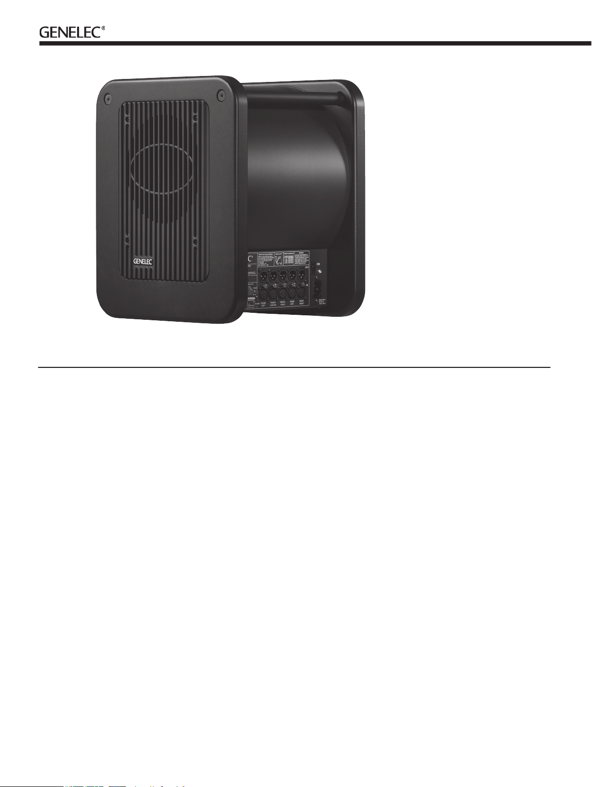
Audio connections are made with bal-
the lower connector row. Next connect XLR
XLR connectors on the upper row to the
Turn the volume control knob on all main
Alternatively, you can connect a stereo
tors of the main loudspeakers and an another
the 7050B. In this configuration the volume
Page 3

to be powered up.
The placement of the subwoofer in the room
the frequency balance and often patient and
woofer and the bass roll-off rate.
from the center of the front wall. The rec-
front wall and floor. Cancellations from the
front wall and floor are also avoided. Front
wall cancellation for the 85 Hz high pass fil-
tered main speakers can be eliminated by
the front wall (see Figure 2).
the left or right so that different room modes
the subwoofer close to a corner will boost
the bass level at lower frequencies and may
Al tho ugh the 705 0B i s ma gne tic all y
further away or try turning the driver side of
the subwoofer away from the screen
than 10 cm (4") of free space in front of the
The reflex port side (opposite of the con-
the reflex port.
fier cooling and unrestricted airflow from the
the room. This leaves sufficient 7,5 centime-
ters (3") of free space on the reflex port side.
The height and depth of the recess should
The subwoofer requires input sensitivity
trol is located on the connector panel of the
the front wall
Page 4

whole system at the crossover frequency.
The graphs above (Fig. 4) show the effect of
The phase difference between the main
tion is found. Acoustic measuring equipment
this equipment is not available, the following
to the “FRONT CENTER” input of the 7050B
Alternatively, you can use a 85 Hz signal fom
you connect (even temporarily) a main loud-
that the test signal is properly reproduced by
Toggle the -180° phase
to the position which gives the lowest sound
the position which gives
the lowest sound level.
the test signal.
test equipment
The following procedure matches the phase
feed pink noise into the "CENTER IN" input of
the subwoofer. Position the microphone at the
tivity of the subwoofer until frequencies below
for the maximum dip of at least -6 dB at the
The “LFE BANDWIDTH” switch allows you to
that do not replay information above 80 Hz on
the LFE channel when the bass management
this setting on lets you know how it translates
The 120 Hz LFE bandwidth setting com-
wid th of 20 - 120 Hz through dedicated
Phase Difference: 0°
85 Hz
Phase Difference: 180°
85 Hz
Phase Difference: 270°
85 Hz
Phase Difference: 90°
85 Hz
Table 1. Suggested Bass Roll-Off settings
Page 5

the main channels when mixing music and
the LFE channel has to be monitored with
The object is to increase the recording head-
The "LFE +10 dB" function on the 7050B
The "LFE
be used in fol-
implemented by another device.
does not req uire the use of +10 dB
gain on the L FE c ha nn el, su ch a s
DVD-Audio (MLP), SACD (DSD) etc.
Digital or DTS soundtrack. The decoder
wi ll au tom ati cal ly pr ovi de +1 0 dB
LFE gain.
performed by qualified service
personnel. The subwoofer cabinet or
electronics unit must not be opened.
unearthed mains cable or an unearthed
mains connection as this may
compromise electrical safety.
or moisture. Do not place any objects
filled with liquid, such as vases on the
subwoofer or near it.
sound pressure levels in excess of
85 dB, which may cause permanent
hearing damage.
necessary to maintain sufficient cooling.
Do not obstruct airflow around the
subwoofer.
disconnected from the AC mains service
unless the mains power cord is removed
from the amplifier or the mains outlet.
Warning!
This subwoofer is capable of delivering sound
This product is supplied with a ONE year
the unit. Refer to supplier for full sales and
This is to certify that Genelec 7050B Active
A13: (1999), A14: (1999)
The produc t herew ith complies with the
Ilpo Martikainen
Page 6

7050B Operating Manual
www.genelec.com
AMPLIFIER SECTION
INPUT SECTION
CROSSOVER SECTION
SYSTEM SPECIFICATIONS
Weight
Width
/
/
/
OUTPUT SECTION
Amplifier short term output power
Amplifier system THD at nominal output
pin 1
pin 2
pin 3
Variable from +12 to -6
pin 1
pin 2
pin 3
 Loading...