

Page 1
LSE Series
Operating Manual
Genelec 7050A
Active Subwoofer
Page 2
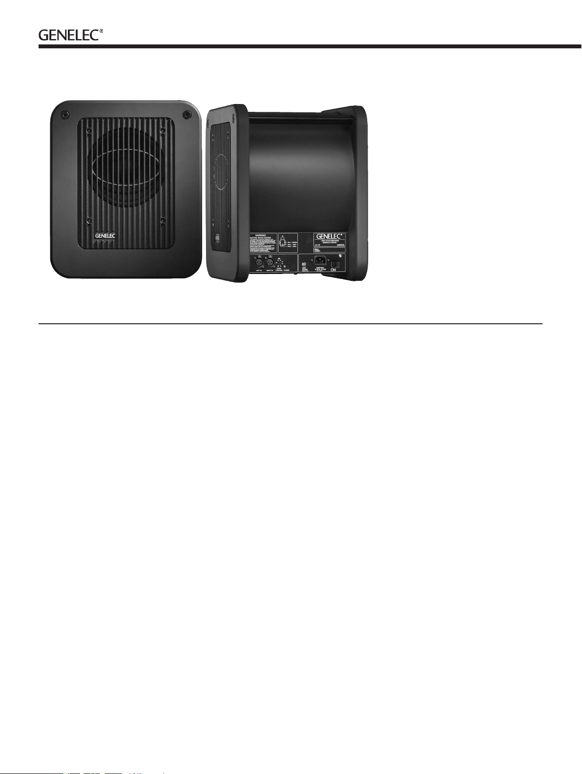
Genelec 7050A Active Subwoofer
General description
Genelec 7050A active subwoofer is a very
compact low frequency loudspeaker,
designed to extend the bass reproduction
of Genelec 1029A, 2029A or 2029B active
monitors in stereo applications. Adding the
7050A to a 1029/2029 system creates a com-
pact neareld monitoring system capable of
a at frequency response from 38 Hz to 20
kHz (± 3 dB).
Driver
The 7050A contains a single 200 mm (8”)
magnetically shielded low frequency driver,
housed in Genelec Laminar Spiral Enclosure
TM
(LSETM).
Crossover
The active crossover contained within the
amplier unit lters the input signals. This
accurately rejects the higher frequencies that
the monitors reproduce, and allows the lower
frequencies to pass. The sensitivity can be
attenuated from 0 dB to -18 dB for easy level
matching with the main loudspeakers. Due to
the input sensitivity of the 7050A subwoofer
it can only be used with Genelec 1029A,
2029A and 2029B active monitors.
Amplifier
The amplier produces 70 W of output power,
with very low THD and IM distortion. Driver
overload protection and power-on signal
muting is included in the amplier circuitry.
The amplier also incorporates thermal over-
load and short circuit protection.
Installation
The subwoofer is supplied with a mains
cable, signal cables to go between the
main monitors and the subwoofer and this
operating manual. Once unpacked inspect
the subwoofer to ensure that it has not been
damaged in transport. Check that the mains
voltage selector switch is set to your local
mains voltage (Subwoofers sold in Europe
have a xed 230 V setting). Ensure that both
the subwoofer and the main monitors are
switched off before making any connections.
Audio connections to the subwoofer are
made with balanced 1/4" Jack / XLR cables
supplied with the subwoofer. Signals from the
source are fed to the XLR input connectors
of the 1029A/2029A/2029B monitors. The
7050A gets its input signal from the 1/4"
Jack "SUB OUT" output connectors of the the
1029A/2029A/2029B monitors (see Figure 1).
When used in conjunction with the 7050A the
"BASS ROLL-OFF" dip switch (switch 2) on
the 1029A/2029A/2029B should be switched
to position "ON". Once all connections have
been made, the subwoofer and main monitors
are ready to be powered up.
Positioning in the room
The placement of the subwoofer in the room
affects the overall frequency response and
sound level of the system dramatically, as at
low frequencies the effects of the room are
strong. Even a slight change in the subwoof-
er's location can make a marked difference
in the frequency balance and often a patient
and methodical experimentation and testing
is needed to nd the optimum placement. The
placement will affect the phase difference
between the main monitors and the subwoofer
and the bass roll-off rate.
First place the subwoofer slightly offset
from the center of the front wall. The
recommended distance to the wall is less than
90 cm / 36" measured from the subwoofer's
driver. This position gives increased acoustic
loading (and SPL) due to the proximity of the
front wall and oor. Cancellations from the
front wall and oor are also avoided. Front
wall cancellation for the 85 Hz high pass
ltered main speakers can be eliminated by
placing them at least 110 cm / 43" away from
the front wall (see Figure 2).
If the frequency balance does not seem
right, try moving the subwoofer slightly to
the left or right so that different room modes
are excited at different levels. Positioning
the subwoofer close to a corner will boost
Page 3

Figure 1. Connecting the 7050A to a pair of G enelec 1029A/2029A/2029B active monitors
Figure 2. Recommended distances to
front wall
the bass level at lower frequencies and may
cause asymmetrical spatial imaging.
Although the 7050A is magnetically
shielded, it may cause colour distortion if
placed near to very sensitive video monitors
or computer displays. Move the subwoofer
further away or try turning the driver side of
the subwoofer away from the screen.
Minimum clearances to walls
or other objects
Do not cover the driver side of the subwoofer
or place the subwoofer so that there is less
than 10 centimeters (4") of free space in front
of the grille.
Make sure that the space underneath the
subwoofer is clear from obstructions. Thick
carpets may block the ventilation clearance
needed for cooling the amplier unit.
The reex port side (opposite of the con-
nector panel side) should always have a
clearance of at least 7,5 centimeters (3") to
any objects to ensure proper functioning of
the reex port.
Flush mounting the subwoofer
If the subwoofer is ush mounted into a wall
or a cabinet, it is important to ensure ampli-
er cooling and unrestricted airow from the
reex port. This can be done by making the
recess 7,5 centimeters (3") wider than the
subwoofer. Place the subwoofer into the right
end of the recess with the driver side facing
the room. This leaves sufcient 7,5 centime-
ters (3") of free space on the reex port side.
The height and depth of the recess should
not be any bigger than what is needed to t
the subwoofer ush with the wall surface.
Setting the input sensitivity
The 7050A is set to the same sensitivity
as the 1029A/2029A/2029B monitors in free
eld conditions. However, when placed near
reecting surfaces the sensitivity typically
needs to be attenuated due to increased
room loading. A typical starting point would
be -4 dB. This is achieved by adjusting the
rotary level control on the amplier plate. The
use of proper measuring equipment together
with careful listening is highly recommended.
The maximum attenuation is -18 dB.
Safety considerations
Genelec 7050A subwoofer has been designed
in accordance with international safety stand-
ards. However, to ensure safe operation and
maintain the unit in safe operating condition,
the following warnings and cautions must be
observed:
• Do not expose the subwoofer to
water or moisture. Do not place
any objects lled with liquid,
such as vases on the
subwoofer or near it.
• Servicing and adjustment must
only be performed by
qualied service personnel.
• Opening the amplier unit is strictly
prohibited except by qualied
service personnel.
• Always use a mains power
connection with protective earth.
Failing to do this may lead
to personal injury.
Warning!
This equipment is capable of delivering sound
pressure levels in excess of 85dB, which may
cause permanent hearing damage.
Maintenance
No user serviceable parts are inside the
amplier unit. Any maintenance of the unit
must only be performed by qualied service
personnel.
Guarantee
This product is supplied with a ONE year
guarantee against manufacturing faults or
defects that might alter the performance of
the unit. Refer to supplier for full sales and
guarantee terms.
Page 4

7050A Operating Manual
SYSTEM SPECIFICATIONS
7050A
Free eld frequency response
(+/- 3 dB) 38 Hz…85 Hz
Maximum shor t term sine wave
SPL output averaged from
45 to 85 Hz, measured in
half space at 1 meter ≥ 100 dB SPL
Maximum peak SPL output with
random pink noise, measured
in half space at 1 meter ≥ 105 dB SPL
Self generated noise level in
free eld @ 1 m on axis
(a-weighted) ≤ 15 dB
Harmonic distortion @ 95 dB SPL
at @ 1 m on axis in half space 40 … 85 Hz
2nd ≤ 3 %
3rd ≤ 2 %
Driver, magnetically shielded 200 mm (8”)
Weight 15 kg (33 lbs)
Dimensions
Height 410 mm (16 1/8”)
Width 350 mm (13 3/4”)
Depth 314 mm (12 3/8”)
CROSSOVER SECTION
7050A
Subsonic lter
(18 dB/octave) below 38 Hz
Crossover frequency,
(sub/main channels) 85 Hz
AMPLIFIER SECTION
7050A
Short ter m amplier output
power (Long term output power
is limited by dr iver unit
protection circuitry) 70 W
Amplier system distortion
at nominal output
THD ≤ 0.08%
Mains voltage 230 V, 115/230 V or 100/200V
according to region
Power consumption (average)
Idle 10 VA
Full output 100 VA
INPUT SECTION
7050A
Input connector XLR female
pin 1 gnd
pin 2 +
pin 3 –
Input impedance 10 kohm balanced
Input level for 100 dB SPL
output @ 1 m 0…–18 dB (referenced to 1029/2029 output)
Genelec Docu ment D0045R001. Copyright Ge nelec Oy 5.2002. All data s ubject to change witho ut prior notice
CONTROLS
7050A
Input sensitivity 0…–18 dB
Inter national e nquiries:
Genele c, Olvitie 5
FIN-74 100, Iisal mi, Finlan d
Phone +358 17 83 881
Fax +358 17 812 267
Email genele c@genelec.com
In the U.S. please c ontact
Genele c, Inc., 7 Tech Ci rcle
Natick, MA 01760
Phone +1 508 652 0900
Fax +1 508 652 0 909
Email genele c.usa@genelec.com
www.genelec.com
 Loading...