


USER MANUAL
4Gon www.4Gon.co.uk info@4gon.co.uk Tel: +44 (0)1245 808295 Fax: +44 (0)1245 808299
GWR Series Router
Content
LIST OF FIGURES .....................................................
LIST OF TABLES .......................................................................................................................................... 7
DESCRIPTION OF THE GPRS/EDGE/HSDPA ROUTER ................................................................................ 8
Examples of Possible Application ............................................................................................................8
Technical Parameters ..................................................................................................................................9
GWR Router features..
...............................................................................................................................10
Product Overview ........................................................................................................................................ 11
Front panel ................................................................................................................................................................. 11
Back panel .................................................................................................................................................................. 11
Top Panel .................................................................................................................................................................... 12
Putting Into Operation .............................................................................................................................. 13
Declaration of conformity ........................................................................................................................14
DEVICE CONFIGURATION........................................................................................................................... 15
DEVICE CONFIGURATION USING WEB APPLICATION...................................................................................... 15
Add/Remove/Update manipulation in tables....................................................................................16
Save/Reload changes ................................................................................................................................ 16
Status Information ..................................................................................................................................... 16
Status - General ..........................................................................................................................................16
Status - Network Information ................................................................................................................ 17
Status - WAN Information ....................................................................................................................... 17
Settings - Network ..................................................................................................................................... 19
Settings - DHCP Server ............................................................................................................................ 20
Settings - WAN Setting............................................................................................................................. 22
Settings - Routing....................................................................................................................................... 25
Port translation ......................................................................................................................................................... 27
Settings – Dynamic Routing Protocol ..................................................................................................27
Routing Information Protocol (RIP)..
RIP routing engine for the GWR Router.............................................................................................................. 28
Settings - VPN Settings ............................................................................................................................ 30
Generic Routing Encapsulation (GRE).............................................................................................................. 30
GRE Keepalive........................................................................................................................................................... 31
Internet Protocol Security (IPSec)..................................................................................................................... 32
Settings - IP Filtering ................................................................................................................................ 37
IP Filtering configuration example..................................................................................................................... 39
Maintenance .................................................................................................................................................. 40
Maintenance - Administrator Password .............................................................................................. 40
Maintenance - Device Identity Settings ............................................................................................. 41
Maintenance - Date/Time Settings.......................................................................................................42
Maintenance - Diagnostics....................................................................................................................... 44
Maintenance - Update Firmware ...........................................................................................................44
Maintenance - Settings Backup ............................................................................................................. 45
Import Configuration File...................................................................................................................................... 45
Export Configuration File....................................................................................................................................... 45
Maintenance - System Reboot ...............................................................................................................46
Maintenance - Default Settings ............................................................................................................. 47
Management - Serial Port ........................................................................................................................ 47
Management - Simple Management Protocol (SNMP) ..................................................................49
Management - Logs ................................................................................................................................... 50
Wizards – Internet Access ..
..................................................................................................................... 52
Wizards – GRE Tunnel............................................................................................................................... 53
Wizards – IPSec Tunnel ............................................................................................................................ 55
Logout ............................................................................................................................................................. 59
................................................................................... 4
................................................................................................................. 27
1

USER MANUAL
4Gon www.4Gon.co.uk info@4gon.co.uk Tel: +44 (0)1245 808295 Fax: +44 (0)1245 808299
GWR Series Router
DEVICE CONFIGURATION USING CONSOLE .....................................................
............................................. 59
Network Settings.........................................................................................................................................60
Static vs. Dynamic IP Addresses.................................................................................................................................... 60
DHCP Server Settings ............................................................................................................................... 61
GPRS/EDGE/HSDPA Settings.................................................................................................................. 61
Routing............................................................................................................................................................62
Administration .............................................................................................................................................. 63
Status .............................................................................................................................................................. 64
eneral System Information .................................................................................................................. 64
G
Network Information.................................................................................................................................. 65
GPRS/EDGE Information .......................................................................................................................... 66
Configuration Wizard .................................................................................................................................67
CONFIGURATION EXAMPLE........................................................................................................................ 68
GWR Router as Internet Router ............................................................................................................68
GRE Tunnel configuration between two GWR Routers.................................................................. 69
GRE Tunnel configuration between GWR Router and third party router ...............................74
IPSec Tunnel configuration between two GWR Routers............................................................... 78
IPSec Tunnel configuration between GWR Router and Cisco Router ......................................85
IPSec Tunnel configuration between GWR Router and Juniper SSG firewall ....................... 91
APENDIX ................................................................................................................................................ 105
A. How to Achieve Maximum Signal Strength with GWR Router?.......................................... 105
Antenna placement ............................................................................................................................................... 105
Antenna Options..................................................................................................................................................... 105
B. Mobile operator GPRS settings ....................................................................................................... 106
Australia....................................................................................................................................................................... 106
Austria.......................................................................................................................................................................... 106
Belgium ........................................................................................................................................................................ 106
Brasil ............................................................................................................................................................................ 106
Canada.......................................................................................................................................................................... 106
China ................................................
Croatia.......................................................................................................................................................................... 107
Czech Republic ............................................................................................................................................................. 107
Denmark....................................................................................................................................................................... 107
Egypt ............................................................................................................................................................................ 107
Estonia.......................................................................................................................................................................... 107
Finland ......................................................................................................................................................................... 107
France........................................................................................................................................................................... 108
Germany....................................................................................................................................................................... 108
Greece ........................................................................................................................................................................... 108
Hongkong ..................................................................................................................................................................... 108
Hungary ....................................................................................................................................................................... 109
India ............................................................................................................................................................................. 109
Indonesia ...................................................................................................................................................................... 109
Ireland .......................................................................................................................................................................... 109
Israel............................................................................................................................................................................. 109
Italy .............................................................................................................................................................................. 110
Japan............................................................................................................................................................................. 110
Lithuania ...................................................................................................................................................................... 110
Luxembourg.................................................................................................................................................................. 110
Macedonian .................................................................................................................................................................. 110
Malaysia ....................................................................................................................................................................... 110
Mexico .......................................................................................................................................................................... 111
Netherlands .................................................................................................................................................................. 111
New Zeleand..........................................
Norway......................................................................................................................................................................... 111
Poland........................................................................................................................................................................... 111
Phillipines..................................................................................................................................................................... 111
Portugal........................................................................................................................................................................ 111
Russia ........................................................................................................................................................................... 112
............................................................................................................................ 107
....................................................................................................................... 111
2

USER MANUAL
4Gon www.4Gon.co.uk info@4gon.co.uk Tel: +44 (0)1245 808295 Fax: +44 (0)1245 808299
Serbia............................................................................................................................................................................ 112
Singapore............................................
Slovakia ........................................................................................................................................................................ 112
Slovenia ........................................................................................................................................................................ 112
South Africa ................................................................................................................................................................. 112
Spain............................................................................................................................................................................. 112
Sweden.......................................................................................................................................................................... 113
Switzerland .................................................................................................................................................................. 113
Taiwan...............................................
Thailand........................................................................................................................................................................ 113
Turkey .......................................................................................................................................................................... 113
UK ................................................................................................................................................................................ 113
Ukraine......................................................................................................................................................................... 114
USA.............................................................................................................................................................................. 114
GWR Series Router
.......................................................................................................................... 112
........................................................................................................................... 113
3

USER MANUAL
4Gon www.4Gon.co.uk info@4gon.co.uk Tel: +44 (0)1245 808295 Fax: +44 (0)1245 808299
GWR Series Router
List of Figures
Figure 1 - GWR Router ..............................................................................................................................................8
Figure 2 - GWR Router front panel ....................
Figure 3 - GWR Router back panel ........................................................................................................................11
Figure 4 - GWR Router top panel side .................................................................................................................. 12
Figure 5 - Declaration of conformity...................................................................................................................... 14
Figure 6 - User authentication .......................
Figure 7 - General Router information ..................................................................................................................17
Figure 8 - Network Information ............................................................................................................................. 18
Figure 9 - WAN Information .................................................................................................................................. 18
Figure 10 - Network parameters configuration page .......................................................................................... 19
Figure 11 - DHCP Server configuration page....................................................................................................... 21
Figure 12 - WAN Settings configuration page .....................................................................................................22
Figure 13 - Routing configuration page ................................................................................................................ 25
Figure 14 - RIP configuration page ........................................................................................................................ 27
Figure 15 - GRE tunnel parameters configuration page .....................................................................................31
Figure 16 - IPSec Summary screen .........................................................................................................................32
Figure 17 - IPSec Settings part I .............................................................................................................................. 33
Figure 18 - IPSec Settings part II............................................................................................................................. 34
Figure 19 - IP Filtering configuration page ........................................................................................................... 38
Figure 20 - IP Filtering configuration example..................................................................................................... 39
Figure 21 - IP Filtering settings............................................................................................................................... 39
Figure 22 - Administrator Password configuration page...................................................................................40
Figure 23 - Device Identity Settings configuration page..................................................................................... 42
Figure 24 - Date/Time Settings configuration page............................................................................................ 42
Figure 25 - Diagnostic page..................................................................................................................................... 44
Figure 26 - Update Firmware page ........................................................................................................................ 45
Figure 27 - File download ............................
Figure 28 - System Reboot page ............................................................................................................................. 46
Figure 29 - Default Settings page ........................................................................................................................... 47
Figure 30 - Serial Port configuration page ............................................................................................................ 48
Figure 31 - SNMP configuration page ................................................................................................................... 50
Figure 32 - Syslog configuration page ................................................................................................................... 51
Figure 33 - Internet Access Wizard - page 1 of 3.................................................................................................. 52
Figure 34 - Internet Access Wizard - page 2 of 3.................................................................................................. 52
Figure 35 - Internet Access Wizard - page 3 of 3.................................................................................................. 53
Figure 36 - GRE Tunnel Wizard - 1 of 4 ................................................................................................................53
Figure 37 - GRE Tunnel Wizard - 2 of 4 ................................................................................................................54
Figure 38 - GRE Tunnel Wizard - 3 of 4 ................................................................................................................54
Figure 39 - GRE Tunnel Wizard - 4 of 4 ................................................................................................................55
Figure 40 - IPSec Tunnel Wizard - 1 of 6 ............................................................................................................... 55
Figure 41 - IPSec Tunnel Wizard - 2 of 6 ............................................................................................................... 56
Figure 42 - IPSec Tunnel Wizard - 3 of 6 ............................................................................................................... 57
Figure 43 - IPSec Tunnel Wizard - 4 of 6 ............................................................................................................... 57
Figure 44 - IPSec Tunnel Wizard - 5 of 6 ............................................................................................................... 58
Figure 45 - IPSec Tunnel Wizard - 6 of 6 ............................................................................................................... 58
Figure 46 - Default serial port parameters ............................................................................................................ 59
Figure 47 - Login menu ........................................................................................................................................... 59
Figure 48 - Main configuration menu..................
Figure 49 - Network parameters ............................................................................................................................60
Figure 50 - Network parameters configuration....................................................................................................61
Figure 51 - DHCP Server configuration ................................................................................................................ 61
Figure 52 - Primary DNS ......................................................................................................................................... 61
....................................................................................................11
.........................................................................................................15
...........................................................................................................46
..................................................................................................60
4

USER MANUAL
4Gon www.4Gon.co.uk info@4gon.co.uk Tel: +44 (0)1245 808295 Fax: +44 (0)1245 808299
GWR Series Router
Figure 53 - Secondary DNS .....................................................................................................................................61
Figure 54 - SIM card selection.......................
.......................................................................................................... 62
Figure 55 - SIM card GSM/UMTS configuration................................................................................................. 62
Figure 56 - GSM/UMTS authentication ................................................................................................................ 62
Figure 57 - Routing menu........................................................................................................................................62
Figure 58 - Routing table (list of all routes) .......................................................................................................... 63
Figure 59 - Administration Menu .......................................................................................................................... 63
Figure 60 - Administrator password ...................
..................................................................................................63
Figure 61 - Network diagnostic utility ..................................................................................................................63
Figure 62 - Date/time parameters.......................................................................................................................... 64
Figure 63 - List of Restore option ........................................................................................................................... 64
Figure 64 - Status Menu........................................................................................................................................... 64
Figure 65 - List of basic system parameters..........................................................................................................65
Figure 66 - Status of LAN network connection.................................................................................................... 66
Figure 67 - GSM/UMTS status ............................................................................................................................... 67
Figure 68 - Configuration wizard...........................................................................................................................67
Figure 69 - GWR Router as Internet router ........................................................................................................... 68
Figure 70 - GRE tunnel between two GWR Routers............................................................................................69
Figure 71 - Network configuration page for GWR Router 1 .............................................................................. 70
Figure 72 - GRE configuration page for GWR Router 1...................................................................................... 71
Figure 73 - Routing configuration page for GWR Router 1................................................................................71
Figure 74 - Network configuration page for GWR Router 2 .............................................................................. 72
Figure 75 - GRE configuration page for GWR Router 2...................................................................................... 73
Figure 76 - Routing configuration page for GWR Router 2................................................................................73
Figure 77 - GRE tunnel between Cisco router and GWR Router.......................................................................74
Figure 78 - Network configuration page ............................................................................................................... 76
Figure 79 - GRE configuration page ...................................................................................................................... 77
Figure 80 - Routing configuration page ................................................................................................................ 77
Figure 81 - IPSec tunnel between two GWR Routers.....
.....................................................................................78
Figure 82 - Network configuration page for GWR Router 1 .............................................................................. 79
Figure 83 - IPSEC configuration page I for GWR Router 1................................................................................. 80
Figure 84 - IPSec configuration page II for GWR Router 1................................................................................. 80
Figure 85 – IPSec start/stop page for GWR Router 1.......................................................................................... 81
Figure 86 - Network configuration page for GWR Router 2 .............................................................................. 82
Figure 87 - IPSEC configuration page I for GWR Router 2................................................................................. 83
Figure 88 - IPSec configuration page II for GWR Router 2................................................................................. 83
Figure 89 – IPSec start/stop page for GWR Router 2.......................................................................................... 84
Figure 90 - IPSec tunnel between GWR Router and Cisco Router .................................................................... 85
Figure 91 - Network configuration page for GWR Router ................................................................................. 86
Figure 92 - IPSEC configuration page I for GWR Router.................................................................................... 87
Figure 93 - IPSec configuration page II for GWR Router.................................................................................... 88
Figure 94 – IPSec start/stop page for GWR Router............................................................................................. 88
Figure 95 - IPSec tunnel between GWR Router and Cisco Router .................................................................... 91
Figure 96 - Network configuration page for GWR Router ................................................................................. 92
Figure 97 - IPSEC configuration page I for GWR Router.................................................................................... 93
Figure 98 - IPSec configuration page II for GWR Router.................................................................................... 94
Figure 99 – IPSec start/stop page for GWR Router............................................................................................. 94
Figure 100 - Network Interfaces (list) ....................................................................................................................95
Figure 101 - Network Interfaces (edit)...................................................................................................................95
Figure 102 - AutoKey Advanced Gateway ........................................................................................................... 96
Figure 103 - Gateway parameters ......................
....................................................................................................97
Figure 104 - Gateway advanced parameters ........................................................................................................ 98
Figure 105 - AutoKey IKE ....................................................................................................................................... 99
Figure 106 - AutoKey IKE parameters................................................................................................................. 100
Figure 107 - AutoKey IKE advanced parameters .............................................................................................. 101
5

USER MANUAL
4Gon www.4Gon.co.uk info@4gon.co.uk Tel: +44 (0)1245 808295 Fax: +44 (0)1245 808299
GWR Series Router
Figure 108 - Routing parameters ..........................................................................................................................102
Figure 109 - Policies from untrust to trust zone.....
............................................................................................103
Figure 110 - Policies from trust to untrust zone................................................................................................. 104
6

USER MANUAL
4Gon www.4Gon.co.uk info@4gon.co.uk Tel: +44 (0)1245 808295 Fax: +44 (0)1245 808299
GWR Series Router
List of Tables
Table 1 - Technical parameters ................................................................................................................................. 9
Table 2 - GWR Router features ........................
Table 3 - Network parameters ................................................................................................................................ 19
Table 4 - DHCP Server parameters .....................
Table 5 - WAN parameters ..................................................................................................................................... 23
Table 6 - Advanced WAN Settings ........................................................................................................................ 24
Table 7 - Routing parameters.................................................................................................................................. 26
Table 8 - RIP parameters ......................................................................................................................................... 28
Table 9 - GRE parameters........................................................................................................................................ 31
Table 10 - IPSec Summary ....................................................................................................................................... 33
Table 11 - IPSec Parameters .................................................................................................................................... 36
Table 12 - IP filtering parameters ...........................................................................................................................38
Table 13 - Administrator password ....................................................................................................................... 41
Table 14 - Device Identity parameters ................................................................................................................... 41
Table 15 - Date/time parameters ........................................................................................................................... 43
Table 16 - Serial port parameters............................................................................................................................ 49
Table 17 - SNMP parameters .................................................................................................................................. 50
Table 18 - Syslog parameters ..................................................................................................................................51
....................................................................................................... 10
................................................................................................... 20
7

USER MANUAL
4Gon www.4Gon.co.uk info@4gon.co.uk Tel: +44 (0)1245 808295 Fax: +44 (0)1245 808299
GWR Series Router
Description of the GPRS/EDGE/HSDPA Router
Thank you for choosing Geneko GWR Router. The GWR Router is a compact electronic device
based on different kind of GSM/UMTS modules which enables data transfers using
GPRS/EDGE/HSDPA technologies. Primarily, the GWR Router expands the capabilities of GSM/UMTS
module by the option of connecting entire LAN through the built-in Ethernet interface. The GWR Router
provides automatic establishment and maintenance of GPRS/EDGE/HSDPA connection. Integrated
DHCP server provides the users simple installation procedure and fast Internet access. Built-in VPN
server provides VPN capabilities like GRE server/client, VPN IPSec/GRE pass trough and VPN IPSec.
F
igure 1 - GWR Router
Examples of Possible Application
• mobile office;
• fleet management;
• security system;
• telemetric;
• remote monitoring;
• vending and dispatcher machines;
8

USER MANUAL
4Gon www.4Gon.co.uk info@4gon.co.uk Tel: +44 (0)1245 808295 Fax: +44 (0)1245 808299
GWR Series Router
Technical Parameters
EMC
LVD EN 60950-1:2001(1st Ed.) and/or EN 60950-1:2001
Complies with
s
tandards
Ethernet interface
Other interfaces
R&TTE
RoHS
C
Standard: IEEE 802.3
Physical layer: 10/100Base-T
Speed: 10/100Mbps
Mode: full or half duplex
1
1 x USB Host
Directive 2004/108/EC
EN 301 489-1 V1.6.1(2005-09)
E
N 301 489-7 V1.3.1(2005-11)
Directive 1999/05/EC
ETSI EN 301 511 V9.0.2
E
N 301 908-1 & EN 301 908-2(v2.2.1)
Directive 2002/95/EC
EU Commission 2005/618/EC, 2005/717/EC, 2005/747/EC,
2006/310/EC, 2006/690/EC, 2006/691/EC and 2006/692/EC
onnector RJ-45
x UART(RS-232C)
T
GPRS
RF characteristics of
GS
M module
RF Connector
Status LED
Power supply
Temperature range
Physical
c
haracteristics
*A
dvanced version: GWR201, GWR202, GWR251, GWR252, GWR301, GWR302
**Base version: GWR201-B, GWR202-B, GWR251-B, GWR252-B
GPRS
E
DGE
GPRS
EDGE
UMTS
HSDPA
S
MA, 50Ω
E
thernet activity / network traffic
Power on
GSM link activity / attached network(GSM, UMTS)
Signal quality
9
– 12VDC / 1000mA
O
peration: -5˚C to +50˚C
Storage: -20˚C to +85˚C
Width x Length x Height = 95 x 135 x 35 mm
Weight 380g
ri-band: 900/1800/1900
GPRS multi-slot class 10, mobile station class B
Quad band: GSM 850/900/1800/1900MHz
EDGE multi-slot class 10, mobile station class B
GPRS multi-slot class 12, mobile station class B
UMTS/HSDPA: Triple band, 850/1900/2100MHz
GSM/GPRS/EDGE: Quad band, 850/900/1800/1900MHz
GPRS multi-slot class 10, mobile station class B
EDGE multi-slot class 10, mobile station class B
Table 1 - Technical parameters
9

USER MANUAL
4Gon www.4Gon.co.uk info@4gon.co.uk Tel: +44 (0)1245 808295 Fax: +44 (0)1245 808299
GWR Series Router
GWR Router features
Feature Short description Base version*
Main Ethernet Configuration
Static IP / DHCP Client
DHCP Server
Routing
IP filtering
NAT
IP forwarding
GRE
GRE Keepalive
IPSec pass-through
IPsec
SNMP
RIP
NTP
Failover
Ser2net
Static and dynamic IP address
D
HCP Server support
S
tatic
I
P address / Network filtering
N
AT on WAN interface
I
P, TCP, UDP packets from WAN to LAN
G
eneric Routing Encapsulation is a tunneling
protocol that can encapsulate a wide variety of
network layer protocol packet types inside IP
tunnels
K
eepalive for GRE tunnels
E
SP tunnels
I
nternet Protocol Security is a suite of protocols for
securing IP communications by authenticating and
encrypting each IP packet of a data stream
S
imple Network Management Protocol is used in
network management systems to monitor networkattached devices for conditions that warrant
administrative attention
T
he Routing Information Protocol is a dynamic
routing protocol used in local and wide area
networks
T
he Network Time Protocol is a protocol for
synchronizing the clocks of router
F
ailover
S
erial to Ethernet converter
Advanced
v
ersion**
√ √
√ √
√ √
√ √
√ √
√ √
√ √
√ √
√ √
-
√ √
√ √
√ √
√ √
√ √
√
Configuration
WEB Application
Remote configuration
Configuration via
s
erial console
Wizards
Default reset
File Management
Upload firmware
Backup configuration
H
TTP based
A
ccess to web interface over mobile network
basic functionality
full functionality
Internet access
GRE Tunnel
I
PSec Tunnel
b
y external taster and configuration application
b
y WEB
b
y WEB
Table 2 - GWR Router features
√ √
√ √
√ √
-
√ √
√ √
-
√ √
√ √
√ √
√
√
10

USER MANUAL
4Gon www.4Gon.co.uk info@4gon.co.uk Tel: +44 (0)1245 808295 Fax: +44 (0)1245 808299
GWR Series Router
Product Overview
Front panel
On the front panel (Fi
• one RJ45 connector – Ethernet port for connection into local computer network;
• one RJ45 connector for RS232 serial communication;
• reset button;
• one USB connector for connection of additional device;
• Power supply connector.
Ethernet connector LED:
• ACT (yellow) on – Network traffic detected (off when no traffic detected).
• Network Link (green LED) on - Ethernet activity or access point engaged.
gure 2) the following connectors are located:
F
igure 2 - GWR Router front panel
The Reset button can be used for a warm reset or a reset to factory defaults.
Warm reset: If the GWR Router is having problem connecting to the Internet, press and hold in
the Reset button for a second using the tip of a pen.
Reset to Factory Defaults: To restore the default settings of the GWR Router, hold the RESET
button pressed for a few seconds. Restoration of the default configuration will be signaled by blinks of
the first and last signal strength LED on the top panel. This will restore the factory defaults and clear all
custom settings of the GWR Router. You can also reset the GWR Router to factory defaults using the
Maintenance > Default Settings screen.
Back panel
On the back panel of device (Figure 3) the following connectors are located:
• slot for SIM cards;
• SMA connector for connection of the GSM/UMTS antenna;
Figure 3 - GWR Router back panel
11

USER MANUAL
4Gon www.4Gon.co.uk info@4gon.co.uk Tel: +44 (0)1245 808295 Fax: +44 (0)1245 808299
GWR Series Router
Top Panel
There is a sequence of 8 LED indicators on the top of
system current state, device power supply and presence of GSM/UMTS network as well as signal level is
performed.
this device by which the indication of the
F
igure 4 - GWR Router top panel side
LED Indicator Description:
1. Reset (red LED) on – the GWR Router reset state.
2. Power status (green LED) on – Power supply. Power status LED will blink when the GWR
Router is in initializing state.
3. Link (red LED) will blink when connection is active.
4. Signal strength LED indicator:
• -101 or less dBm = Unacceptable (running LED)
• -100 to -91 dBm = Weak (1 LED)
• -90 to -81 dBm = Moderate (2 LED)
• -80 to -75 dBm = Good (3 LED)
• -74 or better dBm = Excellent (4 LED)
• 0 is not known or not detectable (running LED)
Signal strength LED will blink when GPRS/EDGE/UMTS/HSDPA connection is not active.
When GPRS/EDGE connection is active Signal strength LED is on. Reset condition will be
indicated by blinks of the first and last Signal strength LED. When signal quality is not known or
not detectable there will be running LED indication.
12

USER MANUAL
4Gon www.4Gon.co.uk info@4gon.co.uk Tel: +44 (0)1245 808295 Fax: +44 (0)1245 808299
GWR Series Router
Putting Into Operation
Before putting the GWR Router in operation it is necessary to connect all components needed for
the operation:
• GSM antenna;
• Ethernet cable and
• SIM card must be inserted.
And finally, device should have power supply by power supply connector and the attached
adaptor.
SIM card must not be changed, installed or taken out
performed when power supply is not connected.
while device operates. This procedure is
13

USER MANUAL
4Gon www.4Gon.co.uk info@4gon.co.uk Tel: +44 (0)1245 808295 Fax: +44 (0)1245 808299
GWR Series Router
Declaration of conformity
Figure 5 - Declaration of conformity
14

USER MANUAL
4Gon www.4Gon.co.uk info@4gon.co.uk Tel: +44 (0)1245 808295 Fax: +44 (0)1245 808299
GWR Series Router
Device Configuration
There are two methods which can be used to configure the GWR Router. Administrator can use
following methods to access router:
• Web browser
• Console port
Default access method is by web interface. This method gives administrator full set of privileges
for configuring and monitoring. Configuration, administration and monitoring of the GWR Router can be
performed through the web interface. The default IP address of the router is 192.168.1.1. Another method
is by console port (RJ45 serial interface). This method has limited option for configuring the GWR Router.
Device configuration using web application
The GWR Router’s web-based utility allows you to set up the Router and perform advanced
configuration and troubleshooting. This chapter will explain all of the functions in this utility.
For local access of the GWR Router’s web-based utility, launch your web browser, and enter the
Router’s default IP address, 192.168.1.1, in the address field. A login screen prompts you for your User
name and Password. Default administration credentials are admin/admin.
For administration by web interface please enter IP address of router into web browser. Please
disable Proxy server in web browser before proceed.
F
igure 6 - User authentication
After successfully finished process of authentication of Username/Password you can access Main
Configuration Menu – which is shown at Figure 7.
You can set all parameters of the GWR Router using web application. All functionality and
parameters are grouped through a few main tabs (windows).
15

USER MANUAL
4Gon www.4Gon.co.uk info@4gon.co.uk Tel: +44 (0)1245 808295 Fax: +44 (0)1245 808299
GWR Series Router
Add/Remove/Update manipulation in tables
To Add a new row (new rule or new parameter) in the table please do following:
• Enter data in fields at the bottom row of the table (separated with a line).
• After entering data in all fields click Add link.
To Update the row in the table:
• Change data directly in fields you want to change
To Remove the row from the table:
• Click Remove link to remove selected row from the table.
Save/Reload changes
To save all the changes in the form press Save button. By clicking Save data are checked for validity. If
they are not valid, error message will be displayed. To discard changes press the Reload button. By
clicking Reload, previous settings will be loaded in the form.
Status Information
The GWR Router’s Status menu provides general information about router as well as real-time
network information. Status menu has three parts:
General Information,
Network Information (LAN),
WAN Information.
Status - General
General Information Tab provides general information about device type, device firmware
version, OS version, hardware resources utilization, MAC address of LAN port and Up Time since last
reboot. Screenshot of General Router information is shown at Figure 7. Data in Status menu are read only
and can not be changed by user. If you want to refresh screen data press Refresh button.
SIM Card detection is performed only at time booting the system.
16

USER MANUAL
4Gon www.4Gon.co.uk info@4gon.co.uk Tel: +44 (0)1245 808295 Fax: +44 (0)1245 808299
GWR Series Router
F
igure 7 - General Router information
Status - Network Information
Network Information Tab provides information about Ethernet port and Ethernet traffic
statistics. Screenshot of Network Router information is shown at Figure 8.
Status - WAN Information
WAN Information Tab provides information about GPRS/EDGE/UMTS/HSDPA connection
and GPRS traffic statistics. WAN information menu has three sub menus which provide information about:
GPRS/EDGE/UMTS/HSDPA mobile module(manufacturer and model);
Mobile operator and signal quality;
Mobile traffic statistics.
Screenshot of WAN Router information is shown at Figure 9.
17

USER MANUAL
4Gon www.4Gon.co.uk info@4gon.co.uk Tel: +44 (0)1245 808295 Fax: +44 (0)1245 808299
GWR Series Router
F
igure 8 - Network Information
F
igure 9 - WAN Information
18

USER MANUAL
4Gon www.4Gon.co.uk info@4gon.co.uk Tel: +44 (0)1245 808295 Fax: +44 (0)1245 808299
GWR Series Router
Settings - Network
Click Network Tab, to open the LAN network screen. Use this screen to configure LAN TCP/IP
settings.
Label Description
Use the following IP
a
ddress
IP Address
Subnet Mask
Choose this option if you want to manually configure TCP/IP parameters of
Ethernet port.
T
ype the IP address of your GWR Router in dotted decimal notation.
192.168.1.1 is the factory default IP address.
T
he subnet mask specifies the network number portion of an IP address. The
GWR Router support sub-netting. You must specified subnet mask for your
LAN TCP/IP settings.
Network Tab Parameters
Local DNS T
Reload C
Save
ype the IP address of your local DNS server.
lick Reload to discard any changes and reload previous settings.
C
lick Save button to save your changes back to the GWR Router. Whether you
make changes or not, router will reboot every time you click Save.
Table 3 - Network parameters
A
t the Figure 10 you can see screenshot of Network Tab configuration menu.
F
igure 10 - Network parameters configuration page
19

USER MANUAL
, computers must be manually configured with proper DNS
clients. DNS address is provided by ISP (automatically obtained from WAN side).
Address Exclusions
Add
4Gon www.4Gon.co.uk info@4gon.co.uk Tel: +44 (0)1245 808295 Fax: +44 (0)1245 808299
GWR Series Router
Settings - DHCP Server
The GWR Router can be used as a DHCP (Dynamic Host Configuration Protocol) server on your
network. A DHCP server automatically assigns available IP addresses to computer on your network. If
you choose to enable the DHCP server option, all of the computers on your LAN must be set to obtain an
IP address automatically from a DHCP server. (By default, Windows computers are set to obtain an IP
automatically.)
To use the GWR Router as your network’s DHCP server, click DHCP Server Tab for DHCP
Server setup. The GWR Router has built-in DHCP server capability that assigns IP addresses and DNS
servers to systems that support DHCP client capability.
DHCP Server Parameters
Label Description
D
HCP (Dynamic Host Configuration Protocol) allows individual clients
(workstations) to obtain TCP/IP configuration at startup from a server.
When configured as a server, the GWR Router provides TCP/IP configuration for
Enable DHCP Server
the clients. To activate DHCP server, click check box Enable DHCP Server. To
setup DHCP server fill in the IP Starting Address and IP Ending Address fields.
Uncheck Enable DHCP Server check box to stop the GWR Router from acting as a
DHCP server. When Unchecked, you must have another DHCP server on your
LAN, or else the computers must be manually configured.
IP Starting Address T
IP Ending Address T
Lease Duration T
Primary DNS,
S
econdary DNS
Static Lease
R
eservation
C
his field specifies the first of the contiguous addresses in the IP address pool.
his field specifies last of the contiguous addresses in the IP address pool.
his field specifies DHCP session duration time.
This field specifies IP addresses of DNS server that will be assigns to systems that
support DHCP client capability.
Select None to stop the DHCP Server from assigning DNS server IP address.
When you select None
IP address.
S
elect Used by ISP to have the GWR Router assigns DNS IP address to DHCP
This option is available only if GPRS connection is active. Please establish GPRS
c
onnection first and then choose this option.
Select Used Defined to have the GWR Router assigns DNS IP address to DHCP
clients. DNS address is manually configured by user.
This field specifies IP addresses that will be dedicated to specific DHCP Client
based on MAC address. DHCP server will always assign same IP address to
appropriate client.
T
his field specifies IP addresses that will be excluded from the pool of DHCP IP
address. DHCP server will not assign this IP to DHCP clients.
lick Add to insert (add) new item in table to the GWR Router.
Remove C
lick Remove to delete selected item from table.
Save Click Save to save your changes back to the GWR Router.
Reload Click Reload to discard any changes and reload previous settings.
Table 4 - DHCP Server parameters
20

USER MANUAL
4Gon www.4Gon.co.uk info@4gon.co.uk Tel: +44 (0)1245 808295 Fax: +44 (0)1245 808299
GWR Series Router
F
igure 11 - DHCP Server configuration page
21

USER MANUAL
ISP. You can setup any name for
This field specifies password authentication protocol. From the pop up window
network.
network.
modem connection initialization.
In most cases you have to change only APN field based on parameters obtained
modem initialization. In most
Mark this option in order to enable failover feature. This feature is used when
have been enabled. You specify the amount of time after which Failover
feature brings down current WAN connection (SIM2) and brings up previous
4Gon www.4Gon.co.uk info@4gon.co.uk Tel: +44 (0)1245 808295 Fax: +44 (0)1245 808299
GWR Series Router
Settings - WAN Setting
Click WAN Settings Tab, to open the Wireless screen. Use this screen to configure the GWR
Router GPRS/EDGE/UMTS/HSDPA parameters (Figure 12).
F
igure 12 - WAN Settings configuration page
Label Description
T
Provider
Authentication
Username
Password
his field specifies name of GSM/UMTS
provider.
choose appropriate protocol (PAP, CHAP, PAP - CHAP).
T
his field specifies Username for client authentication at GSM/UMTS
Mobile provider will assign you specific username for each SIM card.
T
his field specifies Password for client authentication at GSM/UMTS
Mobile provider will assign you specific password for each SIM card.
T
his field specifies Dial String for GSM/UMTS
Dial String
from Mobile Provider.
T
Initial String
Enable Failover
his field specifies Initial String for GSM/UMTS
cases you can leave this field at default values.
both SIM
WAN Settings
WAN connection (SIM1).
Reload Click Reload to discard any changes and reload previous settings.
22

USER MANUAL
smaller value via MRU negotiation, pppd will request that the kernel networking
4Gon www.4Gon.co.uk info@4gon.co.uk Tel: +44 (0)1245 808295 Fax: +44 (0)1245 808299
GWR Series Router
Save Click Save to save your changes back to the GWR Router.
Refresh C
lick Refresh to see updated mobile network status.
Connect/
D
isconnect
Click Connect/Disconnect to connect or disconnect from mobile network.
Table 5 - WAN parameters
F
igure 12 shows screenshot of GSM/UMTS tab configuration menu. GSM/UMTS menu is divided into
two parts.
• Upper part provides all parameters for configuration GSM/UMTS connection. These parameters
can be obtained from Mobile Operator. Please use exact parameters given from Mobile Operator.
• Bottom part is used for monitoring status of GSM/UMTS connection (create/maintain/destroy
GSM/UMTS connection). Status line show real-time status: connected/disconnected.
If your SIM Card credit is too low, the GWR Router will performed periodically connect/disconnect
actions.
WAN Settings(advanced)
Label Description
Enable T
Accept Local IP
A
ddress
Accept Remote IP
A
ddress
Idle time before
d
isconnect sec
his field specifies if Advanced WAN settings is enables at the GWR Router.
With this option, pppd will accept the peer's idea of our local IP address, even if
the local IP address was specified in an option.
With this option, pppd will accept the peer's idea of its (remote) IP address, even
if the remote IP address was specified in an option.
Specifies that pppd should disconnect if the link is idle for n seconds. The link is
idle when no data packets are being sent or received.
Refuse PAP Wi
Require PAP
Refuse CHAP
Require CHAP
Max. CHAP challenge
t
ransmissions
CHAP restart interval
s
ec
Refuse MS-CHAP
Refuse MS-CHAPv2
R
authentication.
Wi
CHAP.
R
Authentication Protocol) authentication.
Set the maximum number of CHAP challenge transmissions to n (default 10).
Set the CHAP restart interval (retransmission timeout for challenges) to n
seconds (default 3).
Wi
CHAP.
Wi
CHAPv2.
Refuse EAP Wi
Connection debugging
Maximum Transmit
Enables connection debugging facilities. If this option is given, pppd will log the
contents of all control packets sent or received in a readable form.
Set the MTU (Maximum Transmit Unit) value to n. Unless the peer requests a
Unit bytes
th this option, pppd will not agree to authenticate itself to the peer using PAP.
equire the peer to authenticate using PAP (Password Authentication Protocol)
th this option, pppd will not agree to authenticate itself to the peer using
equire the peer to authenticate using CHAP (Challenge Handshake
th this option, pppd will not agree to authenticate itself to the peer using MS-
th this option, pppd will not agree to authenticate itself to the peer using MS-
th this option, pppd will not agree to authenticate itself to the peer using EAP.
23

USER MANUAL
e it
4Gon www.4Gon.co.uk info@4gon.co.uk Tel: +44 (0)1245 808295 Fax: +44 (0)1245 808299
GWR Series Router
Maximum Receive
U
nit bytes
VJ-Compression D
VJ-Connection-ID
C
ompression
Protocol Field
C
ompression
Address/Control
C
ompression
Predictor-1
C
ompression
BSD Compression D
code send data packets of no more than n bytes through the PPP network
interface.
Set the MRU (Maximum Receive Unit) value to n. Pppd will ask the peer to send
packets of no more than n bytes. The value of n must be between 128 and 16384;
the default is 1500.
isable Van Jacobson style TCP/IP header compression in both directions.
Disable the connection-ID compression option in Van Jacobson style TCP/IP
header compression. With this option, pppd will not omit the connection-ID byte
from Van Jacobson compressed TCP/IP headers.
Disable protocol field compression negotiation in both directions.
Disable Address/Control compression in both directions.
Disable or enable accept or agree to Predictor-1 compression.
isable or enable BSD-Compress compression.
Deflate Compression D
Compression Control
P
rotocol negotiation
Magic Number
n
egotiation
Passive Mode
Silent Mode
Append domain name
Show PAP password
in
log
Time to wait before rein
itiating the link sec
LCP-Echo-Failure
LCP-Echo-Interval
Add a default route
isable or enable Deflate compression.
Disable CCP (Compression Control Protocol) negotiation. This option should
only be required if the peer is buggy and gets confused by requests from pppd
for CCP negotiation.
Disable magic number negotiation. With this option, pppd cannot detect a
looped-back line. This option should only be needed if the peer is buggy.
E
nables the “passive” option in the LCP. With this option, pppd will attempt to
initiate a connection; if no reply is received from the peer, pppd will then just
wait passively for a valid LCP packet from the peer, instead of exiting, as it
would without this option.
Wi
th this option, pppd will not transmit LCP packets to initiate a connection
until a valid LCP packet is received from the peer (as for the “passive” option
with ancient versions of pppd).
A
ppend the domain name d to the local host name for authentication purposes.
When logging the contents of PAP packets, this option causes pppd to show the
password string in the log message.
Specifies how many seconds to wait before re-initiating the link after it
terminates. The holdoff period is not applied if the link was terminated becaus
was idle.
I
f this option is given, pppd will presume the peer to be dead if n LCP echorequests are sent without receiving a valid LCP echo-reply. If this happens, pppd
will terminate the connection. This option can be used to enable pppd to
terminate after the physical connection has been broken (e.g., the modem has
hung up) in situations where no hardware modem control lines are available.
I
f this option is given, pppd will send an LCP echo-request frame to the peer
every n seconds. Normally the peer should respond to the echo-request by
sending an echo-reply. This option can be used with the lcp-echo-failure option to
detect that the peer is no longer connected.
Add a default route to the system routing tables, using the peer as the gateway,
when IPCP negotiation is successfully completed. This entry is removed when
the PPP connection is broken.
Table 6 - Advanced WAN Settings
24

USER MANUAL
4Gon www.4Gon.co.uk info@4gon.co.uk Tel: +44 (0)1245 808295 Fax: +44 (0)1245 808299
GWR Series Router
Settings - Routing
The static routing function determines the path that data follows over your network before and
after it passes through the GWR Router. You can use static routing to allow different IP domain users to
access the Internet through the GWR Router. Static routing is a powerful feature that should be used by
advanced users only. In many cases, it is better to use dynamic routing because it enables the GWR
Router to automatically adjust to physical changes in the network’s layout.
The GWR Router is a full functional router with static routing capability. Figure 13 show
screenshot of Routing Menu.
F
igure 13 - Routing configuration page
Use this menu to setup all routing parameters. Administrator can perform following operations:
• Create/Edit/Remove routes (including default route),
• Reroute GRE and IPSEC packet to dedicated destination at inside network
• Port translation - Reroute TCP and UPD packets to desire destination at inside network.
Routing Settings
Label Description
Routing Table
Enable
Dest Network
Netmask
T
his check box allows you to activate/deactivate this static route.
T
his parameter specifies the IP network address of the final destination.
Routing is always based on network number. If you need to specify a route to a
single host, use a subnet mask of 255.255.255.255 in the subnet mask field to
force the network number to be identical to the host ID.
This parameter specifies the IP netmask address of the final destination.
25

USER MANUAL
Metric
Add
4Gon www.4Gon.co.uk info@4gon.co.uk Tel: +44 (0)1245 808295 Fax: +44 (0)1245 808299
Gateway
Interface
GWR Series Router
This is the IP address of the gateway. The gateway is a router or switch (next
hope) on the same network segment as the device's LAN or WAN port. The
gateway helps forward packets to their final destinations.
For every routing rule enter the IP address of the gateway. Please notice that
ppp0 interface has only one default gateway (provided by Mobile operator) and
because of that that there is no option for gateway when you choose ppp0
interface.
M
etric represents the "cost" of transmission for routing purposes. IP routing
uses hop count as the measurement of cost, with a minimum of 1 for directly
connected networks. Enter a number that approximates the cost for this link.
The number need not be precise, but it must be between 1 and 15. In practice, 2
or 3 is usually a good number.
I
nterface represents the "exit" of transmission for routing purposes. In this case
Eth0 represent LAN interface an ppp0 represent GSM/UMTS mobile interface
of the GWR Router.
VPN Traffic redirection
Enable T
ESP
GRE
Sent to
Enable T
Protocol
Source Port
Dest IP address
Destination Port T
Remove C
Reload
Save
his check box allows you to activate/deactivate this static Protocol translation.
E
ncapsulated Security Payload (ESP) protects the IP packet data from third
party interference, by encrypting the contents using symmetric cryptography
algorithms. Unlike AH, the IP packet header is not protected by ESP. ESP
operates directly on top of IP, using IP protocol number 50.
G
eneric Routing Encapsulation (GRE) is a tunneling protocol designed to
encapsulate a wide variety of network layer packets inside IP tunneling
packets. The original packet is the payload for the final packet. GRE creates a
virtual point-to-point link with routers at remote points on an IP Internet work.
GRE uses IP protocol number 47.
T
his field specifies IP address of the VPN server on local area network. VPN
tunnel ends at this VPN server. You must use VPN tunnel option when
configuring VPN connection, because of NAT.
TCP/UDP Traffic redirection
his check box allows you to activate/deactivate this static port translation.
T
his is the IP protocol type.
T
his is the TCP/UDP port of incoming traffic.
T
his field specifies IP address of the Virtual server (Computer on the LAN
where traffic is redirected).
his is the TCP/UDP port of application.
C
lick Add to insert (add) new item in table to the GWR Router.
lick Remove to delete selected item from table.
C
lick Reload to discard any changes and reload previous settings.
C
lick Save to save your changes back to the GWR Router. After pressing Save
button it make take more then 10 seconds for router to save parameters and
become operational again.
Table 7 - Routing parameters
26
USER MANUAL
4Gon www.4Gon.co.uk info@4gon.co.uk Tel: +44 (0)1245 808295 Fax: +44 (0)1245 808299
Port translation
For incoming data, the GWR Router forwards IP traffic destined for a specific port, port range or
GRE/IPsec protocol from the cellular interface to a private IP address on the Ethernet "side" of the GWR
Router.
GWR Series Router
Settings – Dynamic Routing Protocol
Dynamic routing performs the same function as static routing except it is more robust. Static
routing allows routing tables in specific routers to be set up in a static manner so network routes for
packets are set. If a router on the route goes down the destination may become unreachable. Dynamic
routing allows routing tables in routers to change as the possible routes change.
Routing Information Protocol (RIP)
The Routing Information Protocol (RIP) is a dynamic r
area networks. As such it is classified as an interior gateway protocol (IGP) using the distance-vector
routing algorithm. The Routing Information Protocol provides great network stability, guaranteeing that
if one network connection goes down the network can quickly adapt to send packets through another
connection.
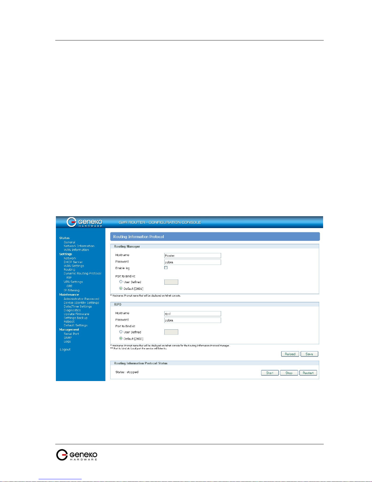
Click RIP Tab, to open the Routing Information Protocol screen. Use this screen to configure the
GWR Router RIP parameters (Figure 14).
outing protocol used in local and wide
F
igure 14 - RIP configuration page
27

USER MANUAL
4Gon www.4Gon.co.uk info@4gon.co.uk Tel: +44 (0)1245 808295 Fax: +44 (0)1245 808299
GWR Series Router
Label Description
Hostname
Password
Enable log
Port to bind at
Hostname
Password
Port to bind at
P
rompt name that will be displayed on telnet console.
L
ogin password.
E
nable log file.
L
ocal port the service will listen to.
P
rompt name that will be displayed on telnet console of the Routing
Information Protocol Manager.
L
ogin password.
L
ocal port the service will listen to.
Routing Information Protocol Status
S
Start
Stop
Restart
Save
Reload
tart RIP.
S
top RIP.
R
estart RIP.
C
lick Save to save your changes back to the GWR Router.
C
lick Reload to discard any changes and reload previous settings.
RIP Settings
Routing Manager
RIPD
Table 8 - RIP parameters
R
IP routing engine for the GWR Router
Use telnet to enter in global configuration mode.
telnet 192.168.1.1 2602 // telnet to eth0 at TCP port 2602///
To enable RIP, use the following commands beginning in global configuration mode:
router# router rip
To associates a network with a RIP routing process, use following commans:
router# network [A.B.C.D/Mask]
By default, the GWR Router receives RIP version 1 and version 2 packets. You can configure the
GWR Router to receive an send only version 1. Alternatively, tou can configure the GWR Router to
receive and send only version 2 packets. To configure GWR Router to send and receive packets from only
one version, use the following command:
router# rip version [1|2] // Same as other router //
Disable route redistribution:
router# no redistribute kernel
router# no redistribute static
router# no redistribute connected
28

USER MANUAL
4Gon www.4Gon.co.uk info@4gon.co.uk Tel: +44 (0)1245 808295 Fax: +44 (0)1245 808299
GWR Series Router
Disable RIP update (optional):
router# passive-interface eth0
router# no passive-interface eth0
Routing protocols use several timer that determine such variables as the frequency of routing
updates, the length of time before a route becomes invalid, an other parameters. You can adjust these
timer to tune routing protocol performance to better suit your internetwork needs. Use following
command to setup RIP timer:
router# timers basic [UPDATE-INTERVAL] [INVALID] [TIMEOUT] [GARBAGE-COLLECT]
router# no timers basic
Configure interface for RIP protocol
router# interface greX
router# ip rip send version [VERSION]
router# ip rip receive version [VERSION]
Disable rip authentication at all interface.
router(interface)# no ip rip authentication mode [md5|text]
Debug commands:
router# debug rip
router# debug rip events
router# debug rip packet
router# terminal monitor
29

USER MANUAL
ld is
transmitted keepalive packets.
Defines the number of times retry after failed keepalives before determining that
4Gon www.4Gon.co.uk info@4gon.co.uk Tel: +44 (0)1245 808295 Fax: +44 (0)1245 808299
GWR Series Router
Settings - VPN Settings
Virtual private network (VPN) is a communications network tunneled through another network,
and dedicated for a specific network. One common application is secure communications through the
public Internet, but a VPN need not have explicit security features, such as authentication or content
encryption. VPNs, for example, can be used to separate the traffic of different user communities over an
underlying network with strong security features.
A VPN may have best-effort performance, or may have a defined Service Level Agreement (SLA)
between the VPN customer and the VPN service provider. Generally, a VPN has a topology more
complex than point-to-point. The distinguishing characteristics of VPNs are not security or performance,
but that they overlay other network(s) to provide a certain functionality that is meaningful to a user
community.
Generic Routing Encapsulation (GRE)
Originally developed by Cisco, generic routing encapsulation (GRE) is now a standard, defined
in RFC 1701, RFC 1702, and RFC 2784. GRE is a tunneling protocol used to transport packets from one
network through another network.
If this sounds like a virtual private network (VPN) to you, that's because it theoretically is:
Technically, a GRE tunnel is a type of a VPN — but it isn't a secure tunneling method. However, you can
encrypt GRE with an encryption protocol such as IPSec to form a secure VPN. In fact, the point-to-point
tunneling protocol (PPTP) actually uses GRE to create VPN tunnels. For example, if you configure
Microsoft VPN tunnels, by default, you use PPTP, which uses GRE.
Solution where you can use GRE protocol:
• You need to encrypt multicast traffic. GRE tunnels can carry multicast packets — just like real
network interfaces — as opposed to using IPSec by itself, which can't encrypt multicast traffic.
Some examples of multicast traffic are OSPF, EIGRP. Also, a number of video, VoIP, and
streaming music applications use multicast.
• You have a protocol that isn't routable, such as NetBIOS or non-IP traffic over an IP network. You
could use GRE to tunnel IPX/AppleTalk through an IP network.
• You need to connect two similar networks connected by a different network with different IP
addressing.
Click VPN Settings Tab, to open the VPN configuration screen. At the Figure 15 you can see
screenshot of GRE Tab configuration menu.
VPN Settings / GRE Tunneling Parameters
Label Description
Enable
Local Tunnel Address
Local Tunnel Netmask
Tunnel Source
Tunnel Destination
Interface
KeepAlive Enable C
Period
T
his check box allows you to activate/deactivate VPN/GRE traffic.
T
his field specifies IP address of virtual tunnel interface.
This field specifies the IP netmask address of virtual tunnel. This fie
unchangeable, always 255.255.255.252
T
his field specifies IP address of tunnel source.
T
his field specifies IP address of tunnel destination.
T
his field specifies GRE interface. This field gets from the GWR Router.
heck for keepalive enable.
Defines the time interval (in seconds) between
Enter a number from 3 to 60 seconds.
Retries
the tunnel endpoint is down. Enter a number from 1 to 10 times.
30
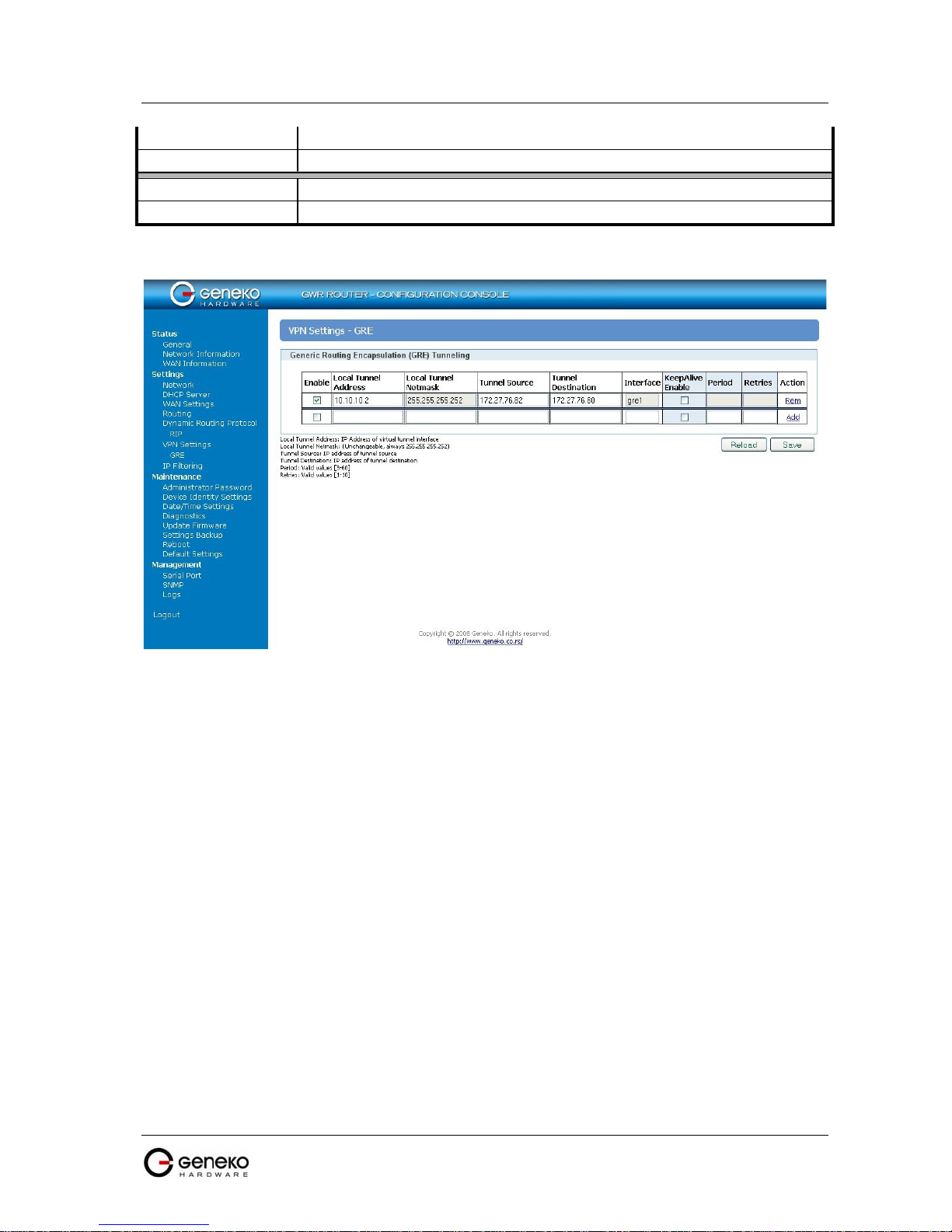
USER MANUAL
4Gon www.4Gon.co.uk info@4gon.co.uk Tel: +44 (0)1245 808295 Fax: +44 (0)1245 808299
GWR Series Router
Add
Remove
Reload
Save
Click Add to insert (add) new item in table to the GWR Router.
C
lick Remove to delete selected item from table.
C
lick Reload to discard any changes and reload previous settings.
C
lick Save to save your changes back to the GWR Router.
Table 9 - GRE parameters
F
igure 15 - GRE tunnel parameters configuration page
GRE Keepalive
GRE tunnels can use periodic status messages, known as keepalives, to verify the integrity of the
tunnel from end to end. By default, GRE tunnel keepalives are disabled. Use the keepalive check box to
enable this feature. Keepalives do not have to be configured on both ends of the tunnel in order to work;
a tunnel is not aware of incoming keepalive packets. You should to define the time interval (in seconds)
between transmitted keepalive packets. Enter a number from 1 to 60 seconds, and the number of times to
retry after failed keepalives before determining that the tunnel endpoint is down. Enter a number from 1
to 10 times.
31

USER MANUAL
button,
current
This field shows both Phase 1 and Phase 2 details, Encryption method
(DES/3DES/AES), Authentication method (MD5/SHA1), and DH Group number
section by displaying the
4Gon www.4Gon.co.uk info@4gon.co.uk Tel: +44 (0)1245 808295 Fax: +44 (0)1245 808299
GWR Series Router
Internet Protocol Security (IPSec)
Internet Protocol Security (IPSec) is a protocol suit
by authenticating and encrypting each IP packet of a data stream.
Click VPN Settings Tab, to open the VPN configuration screen. At the Figure 16 you can see IPSec
Summary screen. This screen gathers information about settings of all defined IPSec tunnels. You can
define up to 5 Device-to-Device tunnels.
e for securing Internet Protocol communication
Label Description
Tunnels Used
Tunnels Available
No
Name
Enable
Status
T
his is the number of IPSec tunnels being defined.
T
his is the number of available, not yet defined, IPSec tunnels.
T
his filed indicates the number of the IPSec tunnel.
F
ield shows the Tunnel Name that you gave to the IPSec tunnel.
T
his field shows if tunnel is enabled or disabled. After clicking on Start
only enabled tunnels will be started.
F
ield indicates status of the IPSec tunnel. Click on Refresh button to see
status of defined IPSec tunnels.
Enc/Auth/Grp
(1/2/5) that you have defined in the IPSec Setup section.
F
Advanced Setup
Local Group
Remote Group
Remote Gateway
ield shows the chosen options from IPSec Advanced
first letters of enabled options.
Field shows the IP address and subnet mask of the Local Group.
Field displays the IP address and subnet mask of the Remote Group.
Field shows the IP address of the Remote Device.
F
igure 16 - IPSec Summary screen
VPN Settings / IPSec Summary
32

USER MANUAL
Device IPSec tunnel. After you have
This button starts the IPSec negotiations between all defined and enabled tunnels.
4Gon www.4Gon.co.uk info@4gon.co.uk Tel: +44 (0)1245 808295 Fax: +44 (0)1245 808299
GWR Series Router
Delete
Edit
Add New Tunnel
Start
Stop
Refresh C
Click on this link to delete the tunnel and all settings for that particular tunnel.
T
his link opens screen where you can change the tunnel’s settings.
C
lick on this button to add a new Device-to-
added the tunnel, you will see it listed in the Summary table.
If the IPSec is already started, Start button is replaced with Restart button.
T
his button will stop all IPSec started negotiations.
lick on this button to refresh the Status field in the Summary table.
Table 10 - IPSec Summary
T
o create a tunnel click Add New Tunnel button. Depending on your selection, the Local Group
Setup and Remote Group Setup settings will differ. Proceed to the appropriate instructions for your
selection.
F
igure 17 - IPSec Settings part I
33

USER MANUAL
Only a specific IP address will be able to
The Local Security Gateway Type you select should match the Remote Security
ternet) IP address of the Router automatically appears. If the
this field is without IP
Select the local LAN user(s) behind the Router that can use this IPSec tunnel.
The Local Security Group Type you select should match the Remote Security
Select the remote LAN user(s) behind the Router at the other end that can use this
e Remote Security Group Type you select should match the Local Security
Select the remote LAN user(s) behind the Router at the other end that can use this
The Remote Security Group Type you select should match the Local Security
4Gon www.4Gon.co.uk info@4gon.co.uk Tel: +44 (0)1245 808295 Fax: +44 (0)1245 808299
GWR Series Router
Label Description
Tunnel Number
Tunnel Name
Enable
T
his number will be generated automatically and it represents the tunnel number.
E
nter a name for the IPSec tunnel. This allows you to identify multiple tunnels
and does not have to match the name used at the other end of the tunnel.
C
heck this box to enable the IPSec tunnel.
Select the type you want to use: IP Only -
Local Security
G
ateway Type
establish a tunnel.
N
OTE:
Gateway Type selected on the IPSec device at the other end of the tunnel
T
he WAN (or In
IP Address
Router is not yet connected to the GSM/UMTS network
address.
F
igure 18 - IPSec Settings part II
VPN Settings / IPSec Settings
Local Security Group
T
ype
Select the type you want to use: IP or Subnet.
N
OTE:
Group Type selected on the IPSec device at the other end of the tunnel.
IP Address
Subnet Mask
Remote Security
G
ateway Type
O
nly the computer with a specific IP address will be able to access the tunnel.
E
nter the subnet mask.
IPSec tunnel. Select the type you want to use: IP or Subnet.
N
Th
OTE:
Group Type selected on the IPSec device at the other end of the tunnel.
IP Address
Remote Security Group
Type
O
nly the computer with a specific IP address will be able to access the tunnel.
IPSec tunnel. Select the type you want to use: IP or Subnet.
NOTE:
Group Type selected on the IPSec device at the other end of the tunnel.
34

USER MANUAL
4Gon www.4Gon.co.uk info@4gon.co.uk Tel: +44 (0)1245 808295 Fax: +44 (0)1245 808299
GWR Series Router
IP Address
Subnet Mask
IPSec Setup
Keying Mode
Phase 1 DH Group
Phase 1 Encryption
Phase 1 Authentication
Phase 1 SA Life Time
Perfect Forward
S
ecrecy
Phase 2 DH Group
Phase 2 Encryption
Phase 2 Authentication
Only the computer with a specific IP address will be able to access the tunnel.
E
nter the subnet mask.
I
n order to establish an encrypted tunnel, the two ends of an IPSec tunnel must
agree on the methods of encryption, decryption and authentication. This is done
by sharing a key to the encryption code. For key management, the Router uses
only IKE with Preshared Key mode.
I
KE with Preshared Key
IKE is an Internet Key Exchange protocol used to negotiate key material for
Security Association (SA). IKE uses the Preshared Key to authenticate the remote
IKE peer. Both ends of IPSec tunnel must use the same mode of key management.
P
hase 1 is used to create the SA. DH (Diffie-Hellman) is a key exchange protocol
used during Phase 1 of the authentication process to establish pre-shared keys.
There are three groups of different prime key lengths. Group 1 is 768 bits, Group
2 is 1024 bits and Group 5 is 1536 bits long. If network speed is preferred, select
Group 1. If network security is preferred, select Group 5.
S
elect a method of encryption: DES (56-bit), 3DES (168-bit) or AES-128 (128-bit).
The method determines the length of the key used to encrypt or decrypt ESP
packets. AES-128 is recommended because it is the most secure. Make sure both
ends of the IPSec tunnel use the same encryption method.
Select a method of authentication: MD5 or SHA1. The authentication method
d
etermines how the ESP packets are validated. MD5 is a one-way hashing
algorithm that produces a 128-bit digest. SHA1 is a one-way hashing algorithm
that produces a 160-bit digest. SHA1 is recommended because it is more secure.
Make sure both ends of the IPSec tunnel use the same authentication method.
C
onfigure the length of time IPSec tunnel is active in Phase 1. The default value is
28800 seconds. Both ends of the IPSec tunnel must use the same Phase 1 SA Life
Time setting.
If the Perfect Forward Secrecy (PFS) feature is enabled, IKE Phase 2 negotiation
will generate new key material for IP traffic encryption and authentication, so
hackers using brute force to break encryption keys will not be able to obtain
future IPSec keys. Both ends of the IPSec tunnel must enable this option in order
to use the function.
I
f the Perfect Forward Secrecy feature is disabled, then no new keys will be
generated, so you do not need to set the Phase 2 DH Group. There are three
groups of different prime key lengths. Group 1 is 768 bits, Group 2 is 1024 bits,
and Group 5 is 1536 bits long. If network speed is preferred, select Group 1. If
network security is preferred, select Group 5. You do not have to use the same
DH Group that you used for Phase 1, but both ends of the IPSec tunnel must use
the same Phase 2 DH Group.
P
hase 2 is used to create one or more IPSec SAs, which are then used to key IPSec
sessions. Select a method of encryption: NULL, DES (56-bit), 3DES (168-bit) or
AES-128 (128-bit). It determines the length of the key used to encrypt or decrypt
ESP packets. AES-128 is recommended because it is the most secure. Both ends of
the IPSec tunnel must use the same Phase 2 Encryption setting.
NOTE:
m
If you select a NULL method of encryption, the next Phase 2 Authentication
ethod cannot be NULL and vice versa.
Select a method of authentication: NULL, MD5 or SHA1. The authentication
m
ethod determines how the ESP packets are validated. MD5 is a one-way
hashing algorithm that produces a 128-bit digest. SHA1 is a one-way hashing
algorithm that produces a 160-bit digest. SHA1 is recommended because it is
more secure. Both ends of the IPSec tunnel must use the same Phase 2
35

USER MANUAL
(Main Mode will be used). If network speed is preferred, select Aggressive Mode.
After that router
tunnels by clicking on the
4Gon www.4Gon.co.uk info@4gon.co.uk Tel: +44 (0)1245 808295 Fax: +44 (0)1245 808299
GWR Series Router
Phase 2 SA Life Time
Preshared Key
Aggressive Mode
Compress (IP Payload
C
ompression Protocol
(IP Comp))
Dead Peer Detection
(
DPD)
NAT Traversal
Back
Reload
Save
Authentication setting.
NOTE: If you select a NULL method of authentication, the previous Phase 2 Encryption
m
ethod cannot be NULL.
C
onfigure the length of time an IPSec tunnel is active in Phase 2. The default is
3600 seconds. Both ends of the IPSec tunnel must use the same Phase 2 SA Life
Time setting.
T
his specifies the pre-shared key used to authenticate the remote IKE peer. Enter
a key of keyboard and hexadecimal characters, e.g., Ay_%4222 or 345fa929b8c3e.
This field allows a maximum of 1023 characters and/or hexadecimal values. Both
ends of the IPSec tunnel must use the same Preshared Key.
It is strongly recommended that you periodically change the Preshared Key to
NOTE:
m
aximize security of the IPSec tunnels.
T
here are two types of Phase 1 exchanges, Main Mode and Aggressive Mode.
Aggressive Mode requires half of the main mode messages to be exchanged in
Phase 1 of the SA exchange. If network security is preferred, don't use this option
Both ends of the IPSec tunnel must use the same mode of exchanges.
N
If the GWR Router is at both ends, it is sufficient to enable Aggressive mode only
OTE:
a
t one end and the other end will automatically detect that Aggressive mode is proposed
and switch to this mode.
IP Payload Compression is a protocol that reduces the size of IP datagram. Select
this option if you want the Router to propose compression when it initiates a
connection.
When DPD is enabled, the Router will send periodic HELLO/ACK messages to
check the status of the IPSec tunnel (this feature can be used only when both peers
or IPSec devices of the IPSec tunnel use the DPD mechanism). Once a dead peer
h
as been detected, the Router will disconnect the tunnel so the connection can be
re-established. Specify the interval between HELLO/ACK messages (how often
you want the messages to be sent). The default interval is 20 seconds.
B
oth the IPSec initiator and responder must support the mechanism for detecting
the NAT router in the path and changing to a new port, as defined in RFC 3947.
If you select this mode the Aggressive mode will be automatically selected because
NOTE:
i
t is obligatory option for NAT-T to work properly.
Keep-alive for NAT-T function is enabled by default and cannot be disabled. The
NOTE:
de
fault interval for keep-alive packets is 20 seconds.
C
lick Back to return on IPSec Summary screen.
C
lick Reload to discard any changes and reload previous settings.
C
lick Save to save your changes back to the GWR Router.
automatically goes back and begin negotiations of the
Start button.
Table 11 - IPSec Parameters
36

USER MANUAL
at the GWR
to the GWR
4Gon www.4Gon.co.uk info@4gon.co.uk Tel: +44 (0)1245 808295 Fax: +44 (0)1245 808299
GWR Series Router
Settings - IP Filtering
IP filtering is simply a mechanism that decides which types of IP datagram’s will be processed
normally and which will be discarded. By discarded we mean that the datagram is deleted and
completely ignored, as if it had never been received. You can apply many different sorts of criteria to
determine which datagram’s you wish to filter; some examples of these are:
• Protocol type: TCP, UDP, ICMP, etc.
• Socket number (for TCP/UPD)
• Datagram type: SYN/ACK, data, ICMP Echo Request, etc.
• Datagram source address: where it came from
• Datagram destination address: where it is going to.
It is important to understand at this point that IP filtering is a network layer facility. This means it
doesn't understand anything about the application using the network connections, only about the
connections themselves. The IP filtering rule set is made up of many combinations of the criteria listed
previously.
Use firewall option to set IP addresses from which is possible remote access on the GWR Router.
Demilitarized Zone (DMZ) allows one IP Address to be exposed to the Internet. Because some
applications require multiple TCP/IP ports to be open, DMZ provides this function by forwarding all the
ports to one computer at the same time. In the other words, this setting allows one local user to be
exposed to the Internet to use a special-purpose services such as Internet gaming, Video-conferencing
and etc. It is recommended that you set your computer with a static IP if you want to use this function.
Label Description
T
Disable all
Enable Firewall T
Enable DMZ T
his field specifies if Firewall and DMZ settings are disabled
Router.
his field specifies if Firewall is enabled at the GWR Router.
his field specifies if DMZ settings is enabled at the GWR Router.
Allow access from the following devices
Enable T
IP address T
Service T
Protocol T
Port T
Add C
Remove C
his check box allows/forbidden host to access to the GWR Router.
his field specifies IP address of the host allow access to the GWR Router.
his field specifies service of the host allow access to the GWR Router.
his field specifies protocol of the host allow access to the GWR Router.
his field specifies port of the host allow access to the GWR Router.
lick Add to insert (add) new item in table to the GWR Router.
lick Remove to delete selected item from table.
Allow access from the following networks
IP Filtering
IP Filtering
Enable This check box allows/forbidden host to access to the GWR Router.
IP address This field specifies IP address of the host allow access to the GWR Router.
Subnet mask This field specifies network mask of the network to allow access
37
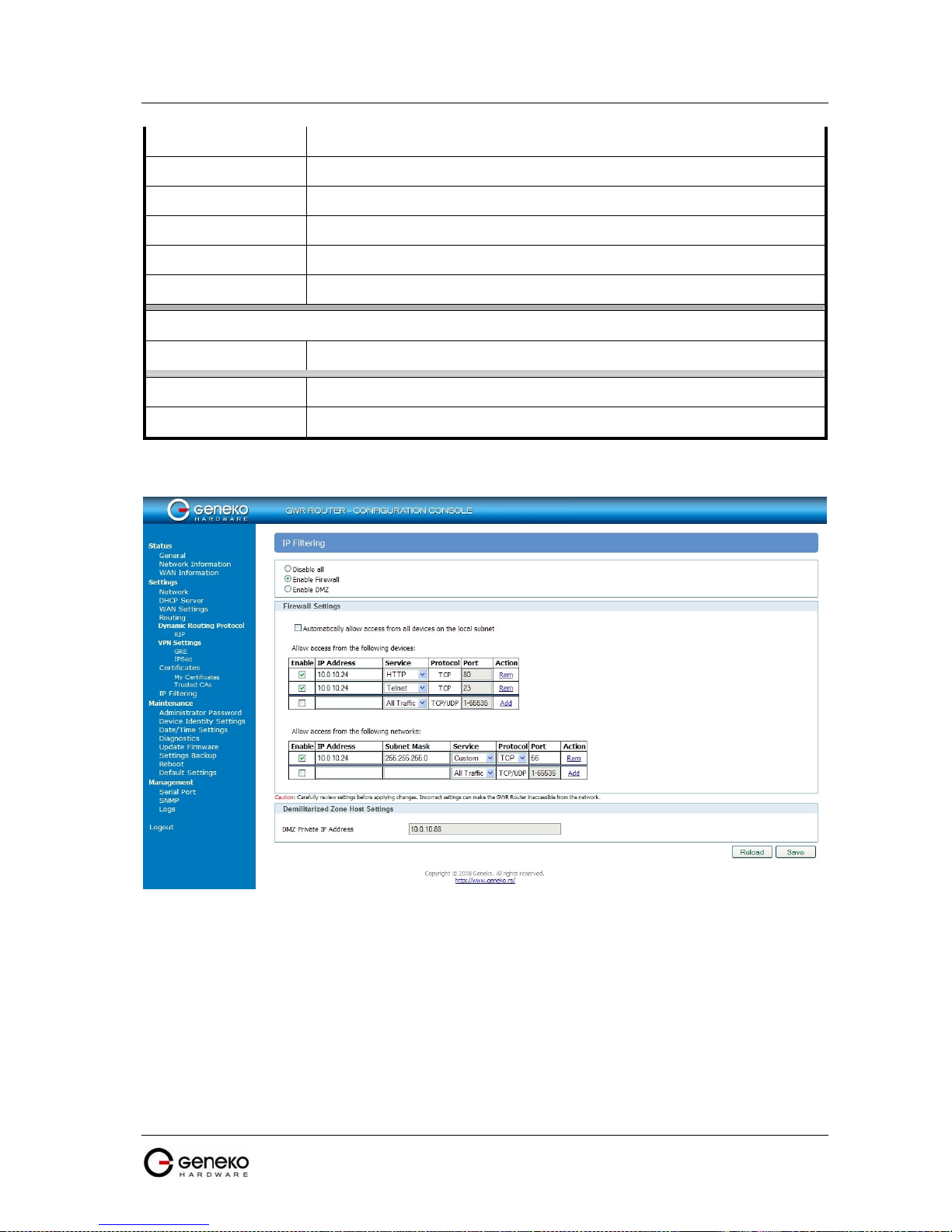
USER MANUAL
4Gon www.4Gon.co.uk info@4gon.co.uk Tel: +44 (0)1245 808295 Fax: +44 (0)1245 808299
GWR Series Router
Router.
Service T
Protocol T
Port T
Add C
Remove C
MZ Private IP Address T
Reload C
Save C
his field specifies service of the host allow access to the GWR Router.
his field specifies protocol of the host allow access to the GWR Router.
his field specifies port of the host allow access to the GWR Router.
lick Add to insert (add) new item in table to the GWR Router.
lick Remove to delete selected item from table.
Demilitarized Zone Host Settings
his check box allows/forbidden host to access to the GWR Router.
lick Reload to discard any changes and reload previous settings.
lick Save to save your changes back to the GWR Router.
Table 12 - IP filtering parameters
F
igure 19 - IP Filtering configuration page
38

USER MANUAL
4Gon www.4Gon.co.uk info@4gon.co.uk Tel: +44 (0)1245 808295 Fax: +44 (0)1245 808299
IP Filtering configuration example
GWR Series Router
T
his example configuration demonstrates how to secure a network with a combination of
routers and a GWR Router.
F
igure 20 - IP Filtering configuration example
Figure 21 - IP Filtering settings
39

USER MANUAL
4Gon www.4Gon.co.uk info@4gon.co.uk Tel: +44 (0)1245 808295 Fax: +44 (0)1245 808299
GWR Series Router
Maintenance
The GWR Router provides administration utilities via web interface. Administrator can setup
basic router’s parameters, perform network diagnostic, update software or restore factory default
settings.
Maintenance - Administrator Password
By Administrator Password Tab it is possible to activate and deactivates device access system
through Username and Password mechanism. Within this menu change of authorization data
Username/Password is also done. Administer Password Tab window is shown on Figure 22.
NOTE: The password cannot be recovered if it is lost
forgotten, you have to reset the Router to its factory default settings; this will remove all of your
configuration changes.
or forgotten. If the password is lost or
F
igure 22 - Administrator Password configuration page
40

USER MANUAL
4Gon www.4Gon.co.uk info@4gon.co.uk Tel: +44 (0)1245 808295 Fax: +44 (0)1245 808299
GWR Series Router
Administrator Password
Label Description
Username
Old Password
Enable Password
A
uthentication
New Password
Confirm Password
Save
Reload
T
his field specifies Username for user (administrator) login purpose.
E
nter the old password. The default is admin when you first power up the GWR
Router.
By this check box you can activate or deactivate function for authentication when
you access to web/console application.
E
nter a new password for GWR Router. Your password must have 20 or fewer
characters and cannot contain any space.
R
e-enter the new password to confirm it.
C
lick Save button to save your changes back to the GWR Router.
C
lick Reload to discard any changes and reload previous settings.
Table 13 - Administrator password
M
aintenance - Device Identity Settings
Within Device Identity Settings Tab there is an option to define name, location of device and
description of device function. These data are kept in device permanent memory. Device Identity
Settings window is shown on Figure 23.
Device Identity Settings
Label Description
Name
Description
Location
Save
Reload
T
his field specifies name of the GWR Router.
T
his field specifies description of the GWR Router. Only for information purpose.
T
his field specifies location of the GWR Router. Only for information purpose.
C
lick Save button to save your changes back to the GWR Router.
C
lick Reload to discard any changes and reload previous settings.
Table 14 - Device Identity parameters
41
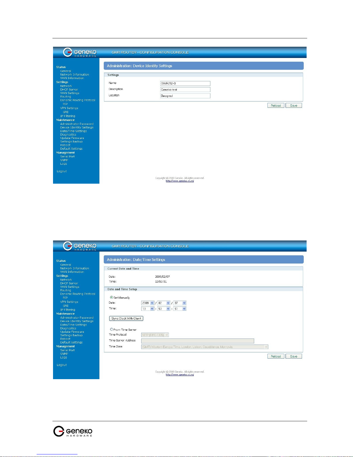
USER MANUAL
4Gon www.4Gon.co.uk info@4gon.co.uk Tel: +44 (0)1245 808295 Fax: +44 (0)1245 808299
GWR Series Router
F
igure 23 - Device Identity Settings configuration page
Maintenance - Date/Time Settings
To set the local time, select Date/Time Settings using the Network Time Protocol (NTP)
automatically or Set the local time manually. Date and time setting on the GWR Router are done through
window Date/Time Settings.
F
igure 24 - Date/Time Settings configuration page
42

USER MANUAL
This field species Date and Time information. You can change date and time by
4Gon www.4Gon.co.uk info@4gon.co.uk Tel: +44 (0)1245 808295 Fax: +44 (0)1245 808299
GWR Series Router
Label Description
Set Manually
S
ets date and time manually as you specify it.
Date/Time Settings
Time/Date
Sync Clock With Client
From Time Server
Time Server Address
Time Zone
Save
Reload
changing parameters.
Date and time setting on the basis of PC calendar.
S
ets the local time using the Network Time Protocol (NTP) automatically.
E
nter the URL or IP address of the NTP server.
S
elect your time zone.
C
lick Save button to save your changes back to the GWR Router.
C
lick Reload to discard any changes and reload previous settings.
Table 15 - Date/time parameters
43

USER MANUAL
4Gon www.4Gon.co.uk info@4gon.co.uk Tel: +44 (0)1245 808295 Fax: +44 (0)1245 808299
GWR Series Router
Maintenance - Diagnostics
The GWR Router provide built-it tool, which is used for troubleshooting network problems. The
ping test bounces a packet of machine on the Internet back to the sender. This test shows if the GWR
Router is able to conect the remote host. If users on the LAN are having problems accessing service on the
Internet, try to ping the DNS server or other machine on network.
Click Diagnostic tab to provide basic diagnostic tool for testing network connectivity. Insert valid
IP address in Hostname box and click Ping. Every time you click Ping router sends four ICMP packets to
destination address.
Before using this tool make sure you know the device
or host’s IP address.
F
igure 25 - Diagnostic page
Maintenance - Update Firmware
You can use this feature to upgrade the GWR Router firmware to the latest version. If you need
to download the latest version of the GWR Router firmware, please visit Geneko support site. Follow the
on-screen instructions to access the download page for the GWR Router.
If you have already downloaded the firmware onto your computer, click Browse button, on
Update firmware Tab, to look for the firmware file. After selection of new firmware version through
Browse button, mechanism the process of data transfer from firmware to device itself should be started.
This is done by Upload button. The process of firmware transfer to the GWR device takes a few minutes
and when it is finished the user is informed about transfer process success.
NOTE: The Router will take a few minutes to upgrade its firmware. During this process, do
not power off the Router or press the Reset button.
44

USER MANUAL
4Gon www.4Gon.co.uk info@4gon.co.uk Tel: +44 (0)1245 808295 Fax: +44 (0)1245 808299
In order to activate new firmware version it is necessary that the user performs system reset. In
the process of firmware version change all configuration parameters are lost and after that the system
continues to operate with default values.
GWR Series Router
F
igure 26 - Update Firmware page
Maintenance - Settings Backup
This feature allows you to make a backup file of your preferences file for the GWR Router. To
save the backup file, you need to export the configuration file. To use the backup preferences file, you
need to import the configuration file that you previously exported.
Import Configuration File
To import a configuration file, first specify where your backup configuration file is located. Click Browse,
and then select the appropriate configuration file.
After you select the file, click Import. This process may take up to a minute. Restart the Router in order to
changes will take effect.
Export Configuration File
To export the Router’s current configuration file, click Export.
45

USER MANUAL
4Gon www.4Gon.co.uk info@4gon.co.uk Tel: +44 (0)1245 808295 Fax: +44 (0)1245 808299
Click Export, and then select the location where you want to store your backup configuration file. By
default, this file will be called confFile.bkg, but you may rename it if you wish. This process may take up
to a minute.
GWR Series Router
F
igure 27 - File download
Maintenance - System Reboot
If you need to restart the Router, Geneko recommends that you use the Reboot tool on this
screen. Click Reboot to have the GWR Router reboot. This does not affect the router’s configuration.
Figure 28 - System Reboot page
46
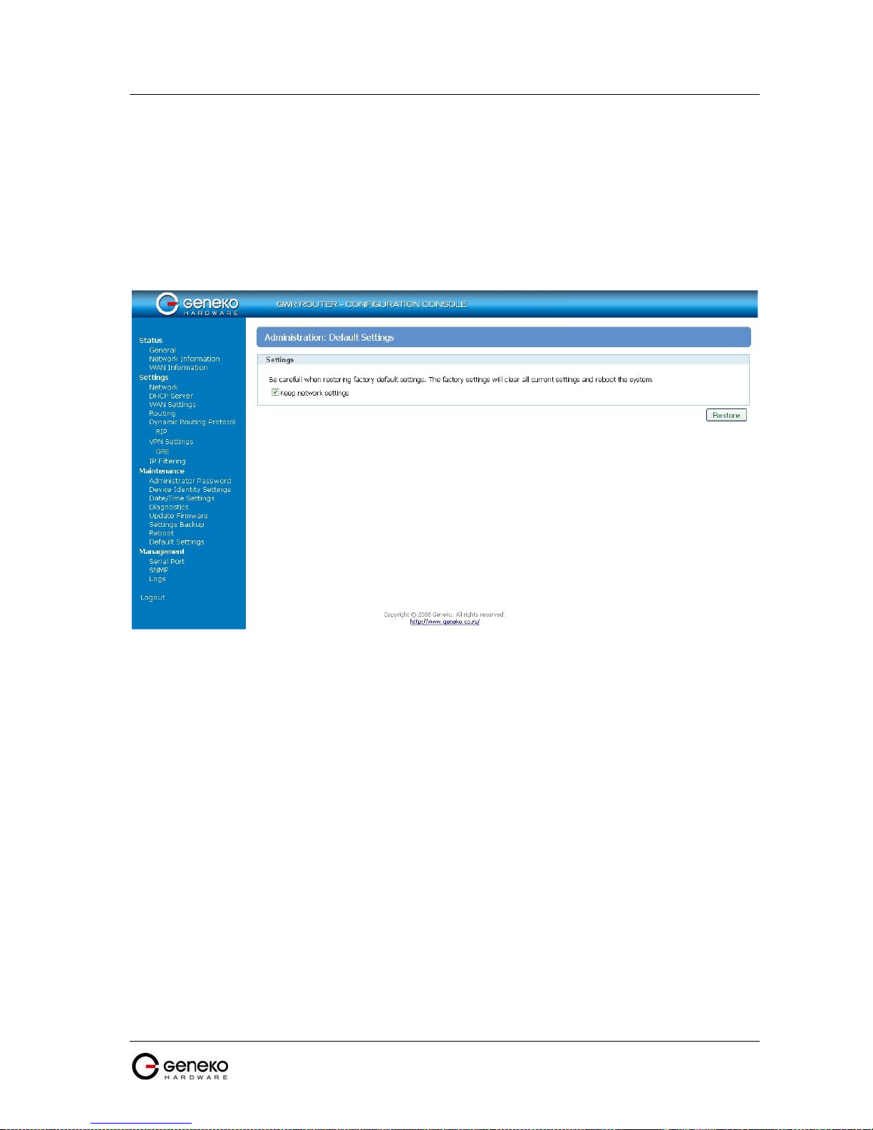
USER MANUAL
4Gon www.4Gon.co.uk info@4gon.co.uk Tel: +44 (0)1245 808295 Fax: +44 (0)1245 808299
GWR Series Router
Maintenance - Default Settings
Use this feature to clear all of your configuration information and restore the GWR Router to its
factory default settings. Only use this feature if you wish to discard all the settings and preferences that
you have configured.
Click Default Setting to have the GWR Router with default parameters. Keep network settings
check-box allows user to keep all network settings after factory default reset. System will be reset after
pressing Restore button.
F
igure 29 - Default Settings page
Management - Serial Port
There are two methods which can be used to configure router serial port. Administrator
can use following serial port settings:
• Configuration console
• Serial to Ethernet converter
The GWR Router provides a way for a user to connect from a network connection to a
serial port. It provides all the serial port setup, a configuration file to configure the ports, a
control login for modifying port parameters, monitoring ports, and controlling ports. The GWR
Router supports RFC 2217 (remote control of serial port parameters).
Configuration may be performed by serial RS-232C port (DB-9 interface), using
following credentials: user "admin" and initial password "admin". Console port allows partial
administration, configuration and control options.
The GWR Router serial port configuration:
1. Read and follow the User Manual.
2. Connect a serial console cable to the RJ45 console port.
47

USER MANUAL
4Gon www.4Gon.co.uk info@4gon.co.uk Tel: +44 (0)1245 808295 Fax: +44 (0)1245 808299
GWR Series Router
3. Serial port parameters:
• Baud rate: 57600,
• Data bits: 8,
• Parity: None,
• Stop bits: 1,
• Flow control: None.
Click Serial Port Tab to open the Serial Port Configuration screen. Use this screen to
configure the GWR Router serial port parameters (Figure 30).
F
igure 30 - Serial Port configuration page
48

USER MANUAL
Serial
Flow control manages data flow between devices in a network to ensure
enables the port and runs
4Gon www.4Gon.co.uk info@4gon.co.uk Tel: +44 (0)1245 808295 Fax: +44 (0)1245 808299
GWR Series Router
Label Description
Enable configuration
c
onsole
Enable serial-Ethernet
c
onverter
Bits per second
Enable router configuration console. Default serial port parameters are:
port parameters: baud rate - 57600, data bits - 8, parity - none, stop bits 1, flow control - none.
Enable serial to Ethernet converter. This provides a way for a user to
connect from a network connection to a serial port.
T
he unit and attached serial device, such as a modem, must agree on a
speed or baud rate to use for the serial connection. Valid baud rates are
300, 1200, 2400, 4800, 9600, 19200, 38400, 57600 or 115200.
Serial Port Settings
Data bits
Parity
Stop bits
Flow control
Bind to port
Type of socket
Reload C
Save
I
ndicates the number of bits in a transmitted data package.
C
hecks for the parity bit. None is the default.
T
he stop bit follows the data and parity bits in serial communication. It
indicates the end of transmission. The default is 1.
it is processed efficiently. Too much data arriving before a device is
p
repared to manage it causes lost or retransmitted data. None is the
default.
N
umber of the TCP/IP port to accept connections from for this device.
E
ither raw, brawl or telnet. raw enables the port and transfers all data asis between the port and the long. rawlp enables the port and transfers all
input data to device, device is open without any termios setting. It
allows using printers connected to them. telnet
the telnet protocol on the port to set up telnet parameters. This is most
u
seful for using telnet.
lick Reload to discard any changes and reload previous settings.
C
lick Save button to save your changes back to the GWR Router and
activate/deactivate serial to ethernet converter.
Table 16 - Serial port parameters
M
anagement - Simple Management Protocol (SNMP)
SNMP, or Simple Network Management Protocol, is a network protocol that provides
network administrators with the ability to monitor the status of the Router and receive
notification of any critical events as they occur on the network. The Router supports SNMP
v1/v2c and all relevant Management Information Base II (MIBII) groups. The appliance replies
to SNMP Get commands for MIBII via any interface and supports a custom MIB for generating
trap messages.
49

USER MANUAL
SNMP agent, click this option to
4Gon www.4Gon.co.uk info@4gon.co.uk Tel: +44 (0)1245 808295 Fax: +44 (0)1245 808299
GWR Series Router
F
igure 31 - SNMP configuration page
SNMP Settings
Label Description
S
Enable SNMP
Get Community
NMP is enabled by default. To disable the
unmark.
C
reate the name for a group or community of administrators who can view
SNMP data. The default is public. It supports up to 64 alphanumeric
characters.
S
ets the port on which SNMP data has been sent. The default is 161. You can
Service Port
specify port by marking on user defined and specify port you want SNMP data
to be sent.
Service Access S
Reload C
Save
ets the interface enabled for SNMP traps. The default is Both.
lick Reload to discard any changes and reload previous settings.
C
lick Save button to save your changes back to the GWR Router and
enable/disable SNMP.
Table 17 - SNMP parameters
M
anagement - Logs
Syslog is a standard for forwarding log messages in an IP network. The term "syslog" is
often used for both the actual syslog protocol, as well as the application or library sending
syslog messages.
Syslog is a client/server protocol: the syslog sender sends a small (less than 1KB) textual
message to the syslog receiver. Syslog is typically used for computer system management and
security auditing. While it has a number of shortcomings, syslog is supported by a wide variety
50

USER MANUAL
4Gon www.4Gon.co.uk info@4gon.co.uk Tel: +44 (0)1245 808295 Fax: +44 (0)1245 808299
GWR Series Router
of devices and receivers across multiple platforms. Because of this, syslog can be used to
integrate log data from many different types of systems into a central repository.
F
igure 32 - Syslog configuration page
The GWR Router supports this protocol and can send its activity logs to an external
server.
Label Description
Enable Syslog M
Service Server
Service Port
Reload C
Save
ark this option in order to enable Syslog feature.
T
he GWR Router can send a detailed log to an external Syslog server. The
Router’s Syslog captures all log activities and includes this information about
all data transmissions: every connection source and destination IP address, IP
service, and number of bytes transferred. Enter the Syslog server name or IP
address.
S
ets the port on which Syslog data has been sent. The default is 514.
You can specify port by marking on user defined and specify port you
want Syslog data to be sent.
lick Reload to discard any changes and reload previous settings.
C
lick Save button to save your changes back to the GWR Router and
enable/disable Syslog.
Syslog Settings
Table 18 - Syslog parameters
51

USER MANUAL
4Gon www.4Gon.co.uk info@4gon.co.uk Tel: +44 (0)1245 808295 Fax: +44 (0)1245 808299
GWR Series Router
Wizards – Internet Access
This wizard helps you to easily configure the Internet connection. You will be asked through
three pages about the parameters for the Internet connection. Click Internet Access Tab to open the
wizard. Use those screens to configure the GWR Router.
Step 1
This screen (Figure 33) enables you to configure the LAN settings.
• IP Address - In this field you must enter the local LAN address of the router.
• Netmask - This is the netmask of the local LAN address of the router.
• Local DNS - This field holds the address of the local DNS server that you want to use.
F
igure 33 - Internet Access Wizard - page 1 of 3
Step 2
This screen (Figure 34) enables you to configure the GSM settings.
• Provider - Enter the name for the Internet connection.
• Authentication - In this menu you can choose the type of the PPP authentication.
• Username - Enter the username for your Internet connection. This username is provided by your
GSM mobile provider.
• Password - Enter the password for your Internet connection. This password is provided by your
GSM mobile provider.
• Dial string - Enter the dial string for your Internet connection. This dial string is provided by
your GSM mobile provider. In most cases you do not need to change this field.
• Initial string - Enter the initial string for your Internet connection. This initial string is provided
by your GSM mobile provider. In most cases you do not need to change this field, except the
APN string which is the Access Point Name of your GSM Internet connection.
• Pin enabled - If you have enabled the PIN code on your mobile card, check this box and enter the
PIN code.
F
igure 34 - Internet Access Wizard - page 2 of 3
52
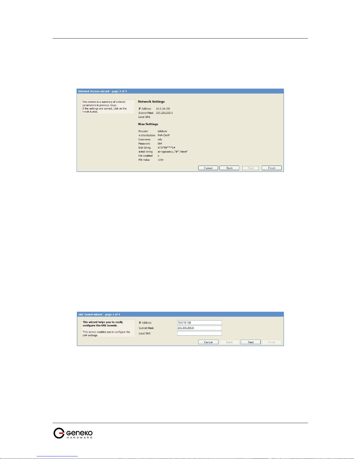
USER MANUAL
4Gon www.4Gon.co.uk info@4gon.co.uk Tel: +44 (0)1245 808295 Fax: +44 (0)1245 808299
Step 3
This screen (Figure 35) is a summary of entered parameters on previous pages. If the settings are
correct, click on the Finish button. If some of parameters are show in red color that parameters are not
entered correctly. Please use the Back button to enter parameters correctly.
GWR Series Router
F
igure 35 - Internet Access Wizard - page 3 of 3
Wizards – GRE Tunnel
This wizard helps you to easily configure the GRE tunnels. You will be asked through four pages
about the parameters for the GRE tunnel. Click GRE Tunnel Tab to open the wizard. Use those screens to
configure the GWR Router.
Step 1
This screen (Figure 36) enables you to configure the LAN settings.
• IP Address - In this field you must enter the local LAN address of the router.
• Netmask - This is the netmask of the local LAN address of the router.
• Local DNS - This field holds the address of the local DNS server that you want to use.
F
igure 36 - GRE Tunnel Wizard - 1 of 4
Step 2
This screen (Figure 37) enables you to configure the GSM settings.
• Provider - Enter the name for the Internet connection.
• Authentication - In this menu you can choose the type of the PPP authentication.
• Username - Enter the username for your Internet connection. This username is provided by your
GSM mobile provider.
53

USER MANUAL
4Gon www.4Gon.co.uk info@4gon.co.uk Tel: +44 (0)1245 808295 Fax: +44 (0)1245 808299
• Password - Enter the password for your Internet connection. This password is provided by your
GSM mobile provider.
• Dial string - Enter the dial string for your Internet connection. This dial string is provided by
your GSM mobile provider. In most cases you do not need to change this field.
• Initial string - Enter the initial string for your Internet connection. This initial string is provided
by your GSM mobile provider. In most cases you do not need to change this field, except the
APN string which is the Access Point Name of your GSM Internet connection.
• Pin enabled - If you have enabled the PIN code on your mobile card, check this box and enter the
PIN code.
Step 3
This screen (Figure 38) enables you to configure the GRE settings.
• Local Tunnel Address - Enter the local IP address of GRE interface.
• Local Tunnel Netmask - This field is automatically generated.
• Tunnel Source - Enter the IP address of the local WAN interface. If the GSM connection is already
established, this field will be automatically generated.
• Tunnel Destination - Enter the IP address of the remote WAN interface.
• Destination Network - Enter the remote network address which will be available through the
GRE tunnel. The route to this address will be inserted automatically.
• Destination Network Netmask - Enter the remote network address netmask.
GWR Series Router
F
igure 37 - GRE Tunnel Wizard - 2 of 4
F
igure 38 - GRE Tunnel Wizard - 3 of 4
Step 4
This screen (Figure 39) is a summary of entered parameters on previous pages. If the settings are
correct, click on the Finish button. If some of parameters are show in red color that parameters are not
entered correctly. Please use the Back button to enter parameters correctly.
54

USER MANUAL
4Gon www.4Gon.co.uk info@4gon.co.uk Tel: +44 (0)1245 808295 Fax: +44 (0)1245 808299
GWR Series Router
Wizards – IPSec Tunnel
F
igure 39 - GRE Tunnel Wizard - 4 of 4
This wizard helps you to easily configure the IPSec tunnels. You will be asked through six pages
about the parameters for the IPSec tunnel. Click IPSec Tunnel Tab to open the wizard. Use those screens
to configure the GWR Router.
Step 1
This screen (Figure 40) enables you to configure the LAN settings.
• IP Address - In this field you must enter the local LAN address of the router.
• Netmask - This is the netmask of the local LAN address of the router.
• Local DNS - This field holds the address of the local DNS server that you want to use.
F
igure 40 - IPSec Tunnel Wizard - 1 of 6
Step 2
This screen (Figure 41) enables you to configure the GSM settings.
• Provider - Enter the name for the Internet connection.
• Authentication - In this menu you can choose the type of the PPP authentication.
• Username - Enter the username for your Internet connection. This username is provided by your
GSM mobile provider.
55

USER MANUAL
4Gon www.4Gon.co.uk info@4gon.co.uk Tel: +44 (0)1245 808295 Fax: +44 (0)1245 808299
GWR Series Router
• Password - Enter the password for your Internet connection. This password is provided by your
GSM mobile provider.
• Dial string - Enter the dial string for your Internet connection. This dial string is provided by
your GSM mobile provider. In most cases you do not need to change this field.
• Initial string - Enter the initial string for your Internet connection. This initial string is provided
by your GSM mobile provider. In most cases you do not need to change this field, except the
APN string which is the Access Point Name of your GSM Internet connection.
• Pin enabled - If you have enabled the PIN code on your mobile card, check this box and enter the
PIN code.
F
igure 41 - IPSec Tunnel Wizard - 2 of 6
Step 3
This screen (Figure 42) enables you to configure the Local and Remote Group parameters of the IPSec
tunnel.
Local Group Setup:
• Gateway Type IP Address - Enter the IP address of the local WAN interface. If the GSM
connection is already established, this field will be automatically generated.
• Local Security Group Type - You can choose IP or Subnet. In case you want only one host on the
local network behind the tunnel you will choose IP. If you want to use a range of addresses
choose Subnet.
Remote Group Setup:
• Gateway Type IP Address - Enter the IP address of the local WAN interface.
• Remote Security Group Type - You can choose IP or Subnet. In case there is only one host on the
remote network behind the tunnel you will choose IP. If there is a range of addresses choose
Subnet.
56

USER MANUAL
4Gon www.4Gon.co.uk info@4gon.co.uk Tel: +44 (0)1245 808295 Fax: +44 (0)1245 808299
GWR Series Router
F
igure 42 - IPSec Tunnel Wizard - 3 of 6
Step 4
This screen () enables you to configure the Phase 1, Phase 2 and Pre-Shared Key parameters of the IPSec
tunnel.
• Phase 1 DH Group - You can choose Group1, Group2 or Group5. Please read the IPSEC section of
documentation for the details.
• Phase 1 Encryption - You can choose DES, 3DES or AES-128. Please read the IPSEC section of
documentation for the details.
• Phase 1 Authentication - You can choose MD5 or SHA1. Please read the IPSEC section of
documentation for the details.
• Perfect Forward Secrecy - Check this box to enable a Perfect Forward Secrecy method. Please
read the IPSEC section of documentation for the details.
• Phase 2 Encryption - You can choose NULL, DES, 3DES or AES-128. Please read the IPSEC
section of documentation for the details.
• Phase 2 Authentication - You can choose NULL, MD5 or SHA1. Please read the IPSEC section of
documentation for the details.
• Preshared Key - Use this field to enter the PreShared Key string. Please read the IPSEC section of
documentation for the details.
F
igure 43 - IPSec Tunnel Wizard - 4 of 6
57
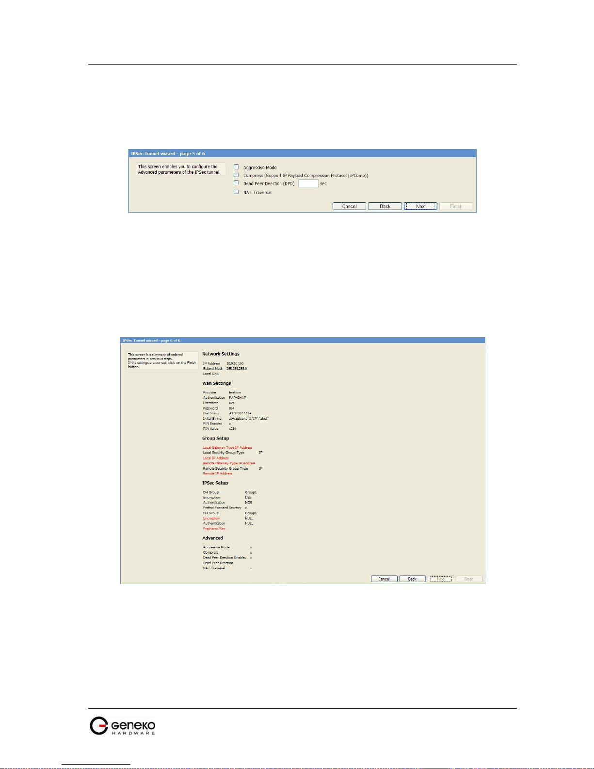
USER MANUAL
4Gon www.4Gon.co.uk info@4gon.co.uk Tel: +44 (0)1245 808295 Fax: +44 (0)1245 808299
Step 5
This screen (Figure 44) enables you to configure advanced parameters of the IPSec tunnel. You
can choose a various advanced parameters for the tunnel. Please read IPSEC section of the
documentation for the details.
GWR Series Router
F
igure 44 - IPSec Tunnel Wizard - 5 of 6
Step 6
This screen (Figure 45) is a summary of entered parameters on previous pages. If the settings are
correct, click on the Finish button. If some of parameters are show in red color that parameters are not
entered correctly. Please use the Back button to enter parameters correctly.
F
igure 45 - IPSec Tunnel Wizard - 6 of 6
58
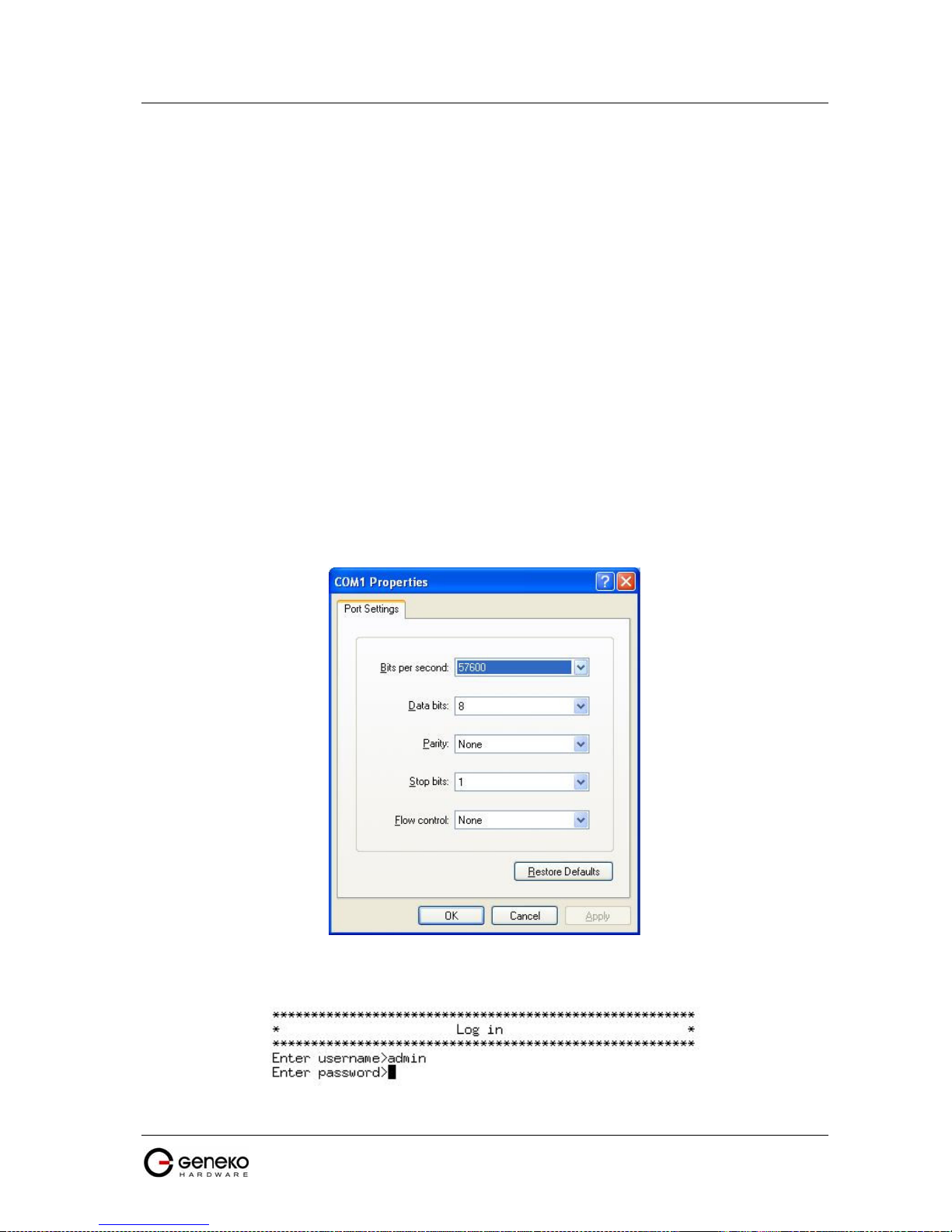
USER MANUAL
4Gon www.4Gon.co.uk info@4gon.co.uk Tel: +44 (0)1245 808295 Fax: +44 (0)1245 808299
GWR Series Router
Logout
The Logout tab is located on the down left-hand corner of the screen. Click this tab to exit the
web-based utility. (If you ex it the web-based utility, you will need to re-enter your User Name and
Password to log in and then manage the Router.)
Device configuration using console
Configuration may be performed via serial RS-232C port (DB-9 interface), using following
credentials: user "admin" and initial password "admin". Console port allows partial administration,
configuration and control options.
The GWR Router serial port configuration:
4. Read and follow the User Manual.
5. Connect a serial console cable to the RJ45 console port.
6. Serial port parameters:
• Baud rate: 57600,
• Data bits: 8,
• Parity: None,
• Stop bits: 1,
• Flow control: None.
F
igure 46 - Default serial port parameters
Configuration may be performed by following credentials the user "admin" with initial password "admin".
Figure 47 - Login menu
59

USER MANUAL
4Gon www.4Gon.co.uk info@4gon.co.uk Tel: +44 (0)1245 808295 Fax: +44 (0)1245 808299
After successfully finished process of authentication of username/password you can access
Custom Setup menu – which is shown at Figure 48.
For navigation through menu please use following tips. The changes in settings will be applied
after pressing “Q” button and process of saving configuration data. If you change network parameters
router will reboot after pressing “Q” button and you will have to wait 1 min before it become available
again. Press “ESC” button if you want to go back and return to previous menu. If you want to logout and
quit console session pres button “L”. When you logout you will have to retype username/password if
you want to log in router again.
GWR Series Router
F
igure 48 - Main configuration menu
Network Settings
To enter the network configuration, select the Network settings menu (Figure 49) item in Custom
Setup. To define the network interface IP address (IP address), the network mask (Netmask), you can
choose between static and dynamic IP configuration option.
F
igure 49 - Network parameters
Static vs. Dynamic IP Addresses
The demand for public IP addresses continues to grow, yet there are a finite number of public IP
addresses available. To solve this problem, wireless carriers have resorted to handing out dynamic IP
addresses instead of static or fixed public addresses. With dynamic IP addresses, each device is given an
IP address for a limited period of time (usually no more than a few hours), and then the IP address is
changed. By using dynamic IP addressing schemes, carriers effectively solve their problem of not having
a sufficient quantity of fixed IP addresses to meet market demand. This creates a challenge for users with
mobile terminated applications who need a fixed address to target. Fortunately, solutions to all of the
challenges above are available using the GWR Router. For example, the network connection type
between the carrier’s network infrastructure and the customer’s data center can provide some flexibility.
Also, a frame relay or Virtual Private Network (VPN) connection between the carrier network and the
customer’s data center allows remote devices to use private IP address assignments for mobile
terminated application connections. A static IP can also be maintained by creating a VPN connection to
the end device.
If you want manually to configure TCP/IP parameters of the GWR Router choose option 1. You
will get page like one on the Figure 50.
60
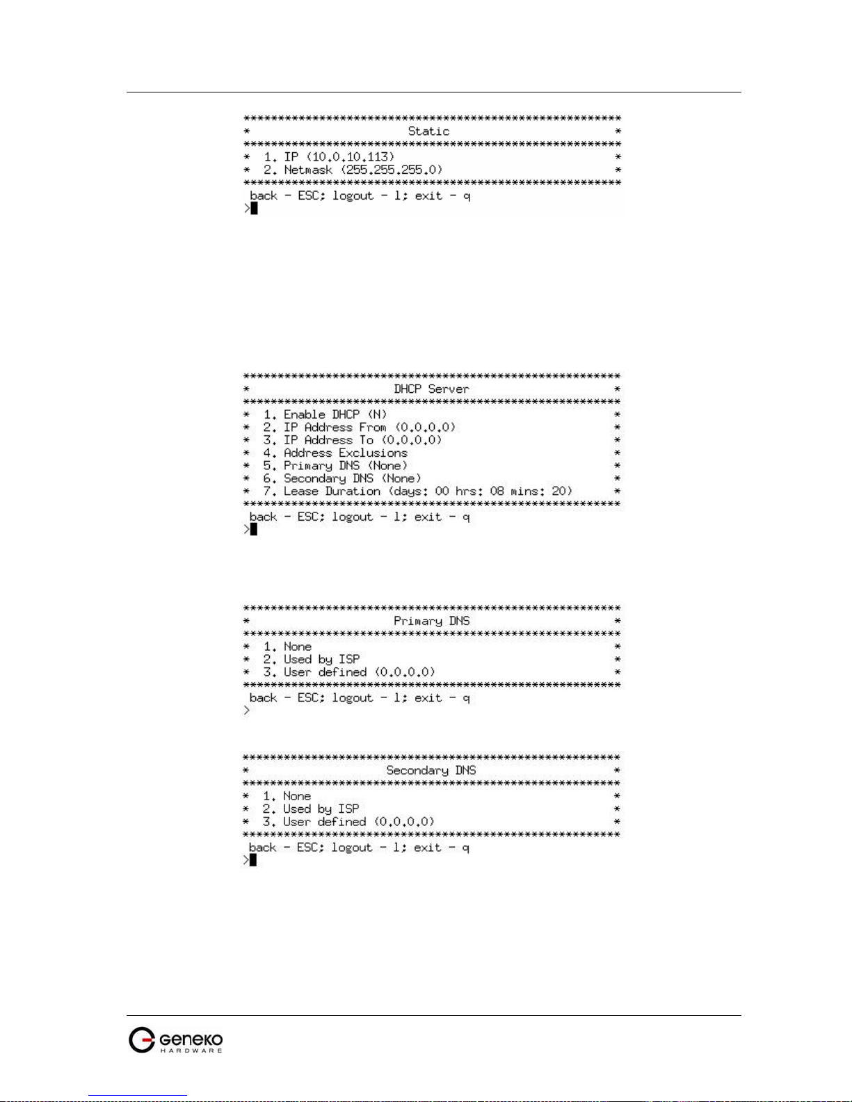
USER MANUAL
4Gon www.4Gon.co.uk info@4gon.co.uk Tel: +44 (0)1245 808295 Fax: +44 (0)1245 808299
GWR Series Router
F
igure 50 - Network parameters configuration
DHCP Server Settings
Option 2 in Custom setup menu (Figure 48) is DHCP server. This menu (Figure 51) enables you to
configure full DHCP server parameters. It is possible to define the beginning – option 2 (IP Address
From) and end – option 3 (IP Address To) of the pool of IP addresses which will be assigned to DHCP
clients as well as DNS and excluded IP addresses (currently under construction).
F
igure 51 - DHCP Server configuration
In the DNS submenu of DHCP Server menu you can configure Primary and Secondary DNS server.
F
igure 52 - Primary DNS
F
igure 53 - Secondary DNS
GPRS/EDGE/HSDPA Settings
To enter the Wireless network GPRS/EDGE/HSDPA configuration, select the GPRS/EDGE
settings menu item in Custom Setup (Figure 54). You can select for which SIM card you want to enter the
parameters (Figure 55).
61

USER MANUAL
4Gon www.4Gon.co.uk info@4gon.co.uk Tel: +44 (0)1245 808295 Fax: +44 (0)1245 808299
Once you choose which SIM card to configure, you can enter initial parameters for
GPRS/EDGE/HSDPA access and you can choose authentication type. These parameters you will get
from your Mobile provider. The changes in settings will apply after pressing “Q” button and saving
configuration data.
GWR Series Router
F
igure 54 - SIM card selection
F
igure 55 - SIM card GSM/UMTS configuration
F
igure 56 - GSM/UMTS authentication
Routing
To enter the Routing configuration, select the Routing menu item in Custom Setup. In this
version of router’s software you are able only to see routing table and not to add/change routes. For
add/edit/remove routes please use web configuration.
F
igure 57 - Routing menu
62

USER MANUAL
4Gon www.4Gon.co.uk info@4gon.co.uk Tel: +44 (0)1245 808295 Fax: +44 (0)1245 808299
GWR Series Router
F
igure 58 - Routing table (list of all routes)
Administration
Administration menu is available under option 5 (Figure 48). The changes in settings will apply
after pressing “Q” button and saving configuration data.
F
igure 59 - Administration Menu
If you want to change default username/password please choose option 1 (Administrator password).
F
igure 60 - Administrator password
The GWR Router has basic diagnostic tool (Ping) for testing network connectivity. If you want to use
Ping utility please use Diagnostic under Administration menu (Figure 61).
F
igure 61 - Network diagnostic utility
If you want to setup/change time and date parameters choose Date/time settings (Figure 62).
63

USER MANUAL
4Gon www.4Gon.co.uk info@4gon.co.uk Tel: +44 (0)1245 808295 Fax: +44 (0)1245 808299
If you want to restore factory default settings you have to possibilities. Factory default settings can be
applied with default network parameters and without default network parameters. The default IP
address of the router is 192.168.1.1. Option 1 (Settings with default network params) enable you to
restore full factory default settings and option 2 (Settings without default network params) enable you to
restore default settings without changing network parameters.
GWR Series Router
F
igure 62 - Date/time parameters
F
igure 63 - List of Restore option
Status
If you want to monitor system and check statuses please choose option Status in Custom menu.
There are options for monitoring LAN and wireless parameters as well as global router parameters.
F
igure 64 - Status Menu
General System Information
The General page (Figure 65) displays the following information about the GWR Router, which
can be useful in device monitoring and troubleshooting.
• Model - The model of the GWR Router device.
• Firmware Version - The current firmware version. This information may be used to help locate
and download new firmware.
• OS - The operating system.
• OS Version - The current OS version.
• CPU Utilization - The amount of CPU resources being used by the GWR Router.
• Up Time - The amount of time the GWR Router has been running since it was last powered on or
rebooted.
• Total/Used/Free Memory - The amount of memory (RAM) available, currently in use, and
currently not being used.
64
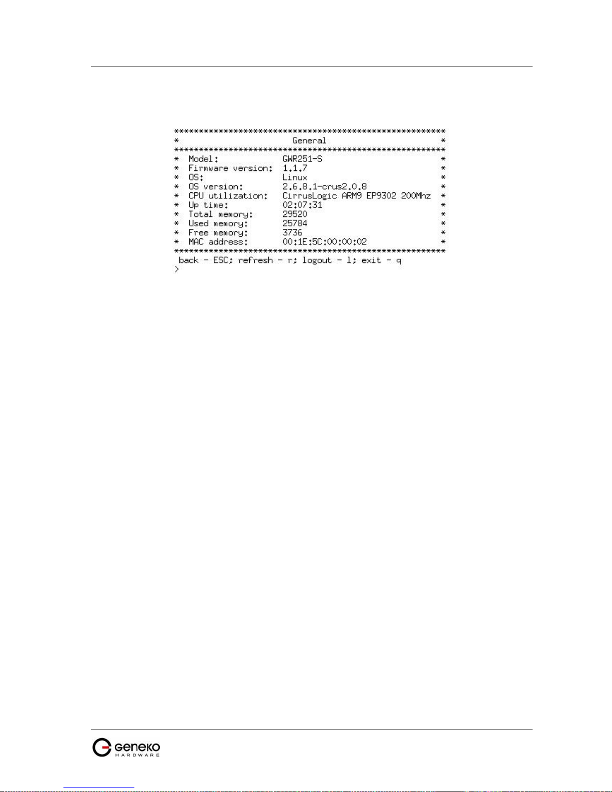
USER MANUAL
4Gon www.4Gon.co.uk info@4gon.co.uk Tel: +44 (0)1245 808295 Fax: +44 (0)1245 808299
• MAC Address - A unique network identifier. All network devices are required to have their own
unique MAC address. The MAC address is on a sticker on you’re the GWR Router. The number
is displayed as 12 hexadecimal digits, usually starting with 00:1E:5C.
GWR Series Router
F
igure 65 - List of basic system parameters
Network Information
The Network information (Figure 66) is used to view more detailed network statistics that may
aid in troubleshooting network communication problems. The statistics displayed are those gathered
since the tables containing the statistics were last cleared. Descriptions of the network statistics follow.
• Protocol - The parameter of networks interface.
• Address - Hardware (unique) address of networks interface.
• Netmask - Mask of network.
• Broadcast Address - Broadcast IP Address.
• Metric - Number of routers, over which packet must pass.
• MAC Address – A unique network identifier. All network devices are required to have their own
unique MAC address. The MAC address is on a sticker on you’re the GWR Router. The number
is displayed as 12 hexadecimal digits, usually starting with 00:1E:5C.
• MTU - Maximal size of packet, which is equipment able transmit.
• Data received - The total number of received bytes.
• Data transmitted - The total number of transmitted bytes.
• RX Packets/ RX Error Packets/ RX Dropped Packets - The number of received packets, number
of errors, dropped packets.
• TX Packets/TX Error Packets/TX Dropped Packets - The number of transmitted packets, number
of errors, dropped packets.
• DHCP Server - Information about DHCP status.
65

USER MANUAL
4Gon www.4Gon.co.uk info@4gon.co.uk Tel: +44 (0)1245 808295 Fax: +44 (0)1245 808299
GWR Series Router
F
igure 66 - Status of LAN network connection
GPRS/EDGE Information
The GPRS/EDGE information page displays the mobile information, mobile connection and
mobile statistics about the GWR Router, which can be useful in device monitoring and troubleshooting.
• Modem Manufacturer - A character string, null-terminated describing the modem module.
• Modem Model - A character string, null-terminated describing the modem module.
• Modem Serial Number - A character string, null-terminated used as a unique ID per modem
module.
• Modem Revision - A character string, null-terminated describing the modem module's firmware
version.
• Operator - The Mobile operator.
• Cell ID - The modem reports this as a 4-hex-digit string. In the mobile statistics it is displayed
both as hex and decimal representations. For example: "00C3 (195)"
• Phone Number - SIM card phone number.
• Signal Strength - Returned as a signed integer value. 0 (zero) indicates no signal. Signal strength
is indicated as a negative value in units of dBm. The following scale indicates the signal Strength
LED ("bars" of signal strength):
• -101 or less dBm = Unacceptable (running LED)
• -100 to -91 dBm = Weak (1 LED)
• -90 to -81 dBm = Moderate (2 LED)
• -80 to -75 dBm = Good (3 LED)
• -74 or better dBm = Excellent (4 LED)
• 0 is not known or not detectable (running LED)
Signal strength LED will blink when GPRS/EDGE connection is not active. When GPRS/EDGE
connection is active Signal strength LED is on. Reset condition will be indicated by blinks of the
first and last Signal strength LED. When signal quality is not known or not detectable there will
be running LED indication.
• Protocol - The parameter of networks interface. PPP interface (active connection to
GPRS/EDGE).
• PPP Address - The IP address of the PPP connection
• WAN Address - The IP address in GPRS/EDGE network provided by the mobile service.
• Primary DNS Address - IP address of the primary DNS server provided by the mobile service.
• Secondary DNS Address - IP address of the secondary DNS server provided by the mobile
service.
66

USER MANUAL
4Gon www.4Gon.co.uk info@4gon.co.uk Tel: +44 (0)1245 808295 Fax: +44 (0)1245 808299
• Data received - The total number of received bytes.
• Data transmitted - The total number of transmitted bytes.
• RX Packets/ RX Error Packets/ RX Dropped Packets - The number of received packets, number
of errors, dropped packets.
• TX Packets/TX Error Packets/TX Dropped Packets - The number of transmitted packets, number
of errors, dropped packets.
GWR Series Router
F
igure 67 - GSM/UMTS status
Configuration Wizard
To enter the Configuration wizard, select the Configuration wizard menu item in Custom Setup.
In this version of router’s software you are able only to see routing table and not to add/change routes.
For add/edit/remove routes please use web configuration.
F
igure 68 - Configuration wizard
67

USER MANUAL
4Gon www.4Gon.co.uk info@4gon.co.uk Tel: +44 (0)1245 808295 Fax: +44 (0)1245 808299
GWR Series Router
Configuration Example
GWR Router as Internet Router
The GWR Routers can be used as Internet router for a single user or for a grooup of users (entire
LAN). NAT function is enabled by default on the GWR Router. The GWR Router uses Network Address
Translation (NAT) where only the mobile IP address is visible to the outside world. All outgoing traffic
uses the GWR Router mobile IP address.
F
igure 69 - GWR Router as Internet router
• Click Network Tab, to open the LAN NETWORK screen. Use this screen to configure LAN
TCP/IP settings. Configure IP address and Netmask.
- IP address: 10.1.1.1
- Netmask: 255.255.255.0
• Press Save to accept the changes.
• Use SIM card with a dynamic/static IP address, obtained from Mobile Operator. (Note the
default gateway may show, or change to, an address such as 10.0.0.1; this is normal as it is the
GSM/UMTS provider’s network default gateway).
• Click WAN Settings Tab to configure parameters necessary for GSM/UMTS connection. All
parameters necessary for connection configuration should be required from mobile operator.
• Check the status of GSM/UMTS connection (WAN Settings Tab). If disconnected please click
Connect button.
• Check Routing Tab to see if there is default route (should be there by default).
• Router will automatically add default route via ppp0 interface.
• Optionally configure IP Filtering and TCP service port settings to block any unwanted incoming
traffic.
• Configure the GWR Router LAN address (10.1.1.1) as a default gateway address on your PCs.
Configure valid DNS address on your PCs.
68

USER MANUAL
4Gon www.4Gon.co.uk info@4gon.co.uk Tel: +44 (0)1245 808295 Fax: +44 (0)1245 808299
GWR Series Router
GRE Tunnel configuration between two GWR Routers
GRE tunnel is a type of a VPN tunnels, but it isn't a secure tunneling method. On the diagram
below (Figure 70) is illustrated simple network with two GWR Routers. Idea is to create GRE tunnel for
LAN to LAN (site to site) connectivity.
F
igure 70 - GRE tunnel between two GWR Routers
The GWR Routers requirements:
• Static IP WAN address for tunnel source and tunnel destination address;
• Source tunnel address should have static WAN IP address;
• Destination tunnel address should have static WAN IP address;
GSM/UMTS APN Type: For GSM/UMTS networks GWR Router connections may require a
Custom APN. A Custom APN allows for various IP addressing options, particularly static IP addresses,
which are needed for most VPN connections. A custom APN should also support mobile terminated data
that may be required in most site-to-site VPNs.
The GWR Router 1 configuration:
• Click Network Tab, to open the LAN NETWORK screen. Use this screen to configure LAN
TCP/IP settings. Configure IP address and Netmask.
- IP Address: 192.168.4.1
- Subnet Mask: 255.255.255.0
- Press Save to accept the changes.
69

USER MANUAL
4Gon www.4Gon.co.uk info@4gon.co.uk Tel: +44 (0)1245 808295 Fax: +44 (0)1245 808299
GWR Series Router
F
igure 71 - Network configuration page for GWR Router 1
• Use SIM card with a static IP address, obtained from Mobile Operator. (Note the default gateway
may show, or change to, an address such as 10.0.0.1; this is normal as it is the GSM/UMTS
provider’s network default gateway).
• Click WAN Settings Tab to configure parameters necessary for GSM/UMTS connection. All
parameters necessary for connection configuration should be required from mobile operator.
• Check the status of GSM/UMTS connection (WAN Settings Tab). If disconnected please click
Connect button.
• Click VPN Settings > GRE to configure GRE tunnel parameters:
- Enable: yes
- Local Tunnel Address: 10.10.10.1
- Local Tunnel Netmask: 255.255.255.252 (Unchangeable, always 255.255.255.252)
- Tunnel Source: 10.251.49.2
- Tunnel Destination: 10.251.49.3
- KeepAlive enable: no
- Period:(none)
- Retries:(none)
- Press ADD to put GRE tunnel rule into GRE table.
- Press Save to accept the changes.
70

USER MANUAL
4Gon www.4Gon.co.uk info@4gon.co.uk Tel: +44 (0)1245 808295 Fax: +44 (0)1245 808299
• Click Routing on Settings Tab to configure GRE Route. Parameters for this example are:
GWR Series Router
F
igure 72 - GRE configuration page for GWR Router 1
- Destination Network: 192.168.2.0
- Netmask: 255.255.255.0
- Interface: gre_x
F
igure 73 - Routing configuration page for GWR Router 1
• Optionally configure IP Filtering and TCP service port settings to block any unwanted incoming
traffic.
• On the device connected on GWR router 1 setup default gateway 192.168.4.1
71

USER MANUAL
4Gon www.4Gon.co.uk info@4gon.co.uk Tel: +44 (0)1245 808295 Fax: +44 (0)1245 808299
GWR Series Router
The GWR Router 2 configuration:
• Click Network Tab, to open the LAN NETWORK screen. Use this screen to configure LAN
TCP/IP settings. Configure IP address and Netmask.
- IP Address: 192.168.2.1
- Subnet Mask: 255.255.255.0
- Press Save to accept the changes.
F
igure 74 - Network configuration page for GWR Router 2
• Use SIM card with a static IP address, obtained from Mobile Operator. (Note the default gateway
may show, or change to, an address such as 10.0.0.1; this is normal as it is the GSM/UMTS
provider’s network default gateway).
• Click WAN Settings Tab to configure parameters necessary for GSM/UMTS connection. All
parameters necessary for connection configuration should be required from mobile operator.
• Check the status of GSM/UMTS connection (WAN Settings Tab). If disconnected please click
Connect button.
• Click VPN Settings > GRE to configure GRE tunnel parameters:
- Enable: yes
- Local Tunnel Address: 10.10.10.2
- Local Tunnel Netmask: 255.255.255.252 (Unchangeable, always 255.255.255.252)
- Tunnel Source: 10.251.49.3
- Tunnel Destination: 10.251.49.2
- KeepAlive enable: no
- Period:(none)
- Retries:(none)
- Press ADD to put GRE tunnel rule into GRE table.
- Press Save to accept the changes.
72

USER MANUAL
4Gon www.4Gon.co.uk info@4gon.co.uk Tel: +44 (0)1245 808295 Fax: +44 (0)1245 808299
• Configure GRE Route. Click Routing on Settings Tab. Parameters for this example are:
GWR Series Router
F
igure 75 - GRE configuration page for GWR Router 2
- Destination Network: 192.168.4.0
- Netmask: 255.255.255.0
F
igure 76 - Routing configuration page for GWR Router 2
• Optionally configure IP Filtering and TCP service port settings to block any unwanted incoming
traffic.
• On the device connected on GWR router 2 setup default gateway 192.168.2.1
73
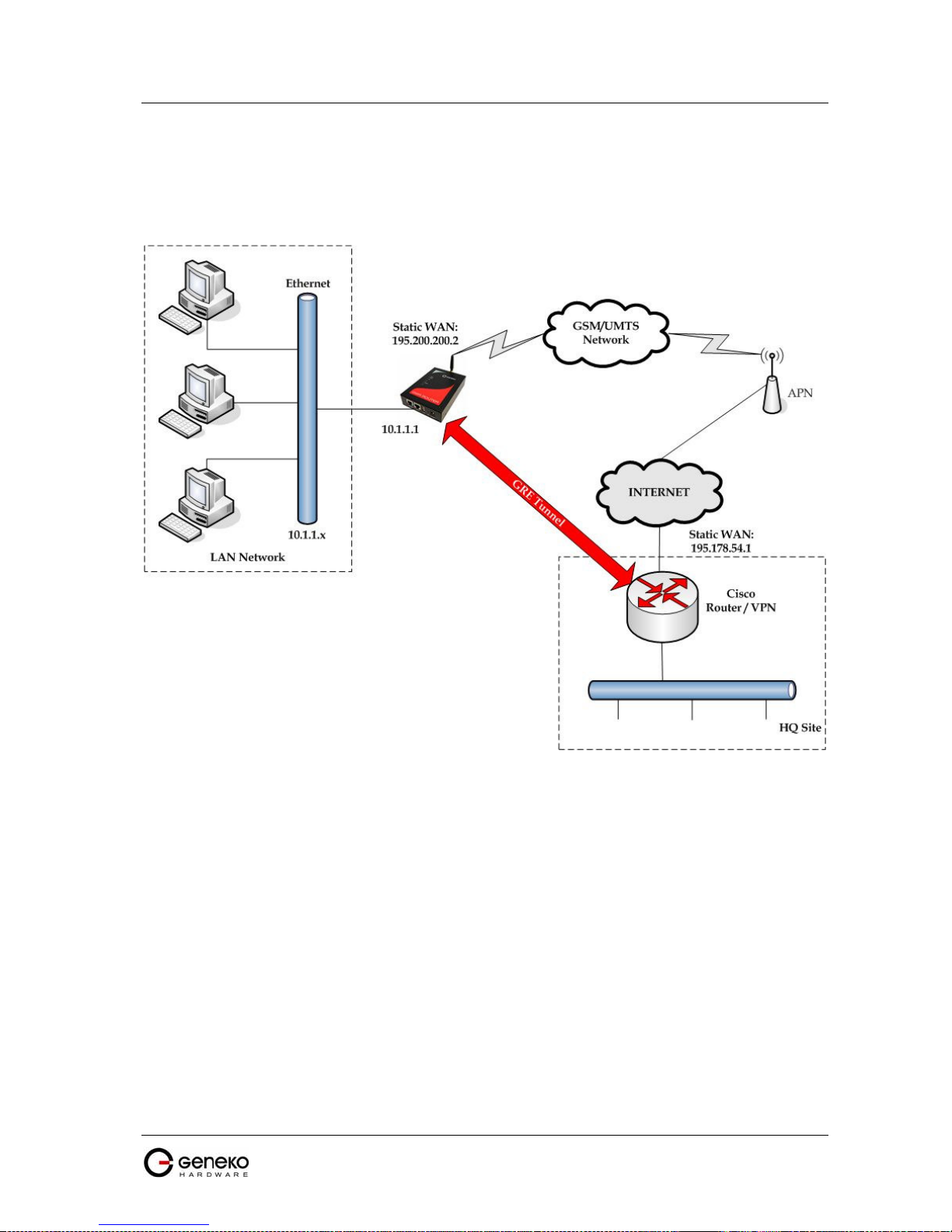
USER MANUAL
4Gon www.4Gon.co.uk info@4gon.co.uk Tel: +44 (0)1245 808295 Fax: +44 (0)1245 808299
GWR Series Router
GRE Tunnel configuration between GWR Router and third party router
GRE tunnel is a type of a VPN tunnels, but it isn't a secure tunneling method. However, you can
encrypt GRE packets with an encryption protocol such as IPSec to form a secure VPN.
On the diagram below (Figure 77) is illustrated simple network with two sites. Idea is to create
GRE tunnel for LAN to LAN (site to site) connectivity.
F
igure 77 - GRE tunnel between Cisco router and GWR Router
GRE tunnel is created between Cisco router with GRE functionality on the HQ Site and the GWR
Router on the Remote Network. In this example, it is necessary for both routers to create tunnel interface
(virtual interface). This new tunnel interface is its own network. To each of the routers, it appears that it
has two paths to the remote physical interface and the tunnel interface (running through the tunnel). This
tunnel could then transmit unroutable traffic such as NetBIOS or AppleTalk.
The GWR Router uses Network Address Translation (NAT) where only the mobile IP address is
visible to the outside. All outgoing traffic uses the GWR Router WAN/VPN mobile IP address. HQ Cisco
router acts like gateway to remote network for user in corporate LAN. It also performs function of GRE
server for termination of GRE tunnel. The GWR Router act like default gateway for Remote Network and
GRE server for tunnel.
1. HQ router requirements:
• HQ router require static IP WAN address;
• Router or VPN appliance have to support GRE protocol;
• Tunnel peer address will be the GWR Router WAN's mobile IP address. For this reason, a static
mobile IP address is preferred on the GWR Router WAN (GPRS) side;
• Remote Subnet is remote LAN network address and Remote Subnet Mask is subnet of remote
LAN.
74

USER MANUAL
4Gon www.4Gon.co.uk info@4gon.co.uk Tel: +44 (0)1245 808295 Fax: +44 (0)1245 808299
GWR Series Router
2. The GWR Router requirements:
• Static IP WAN address;
• Peer Tunnel Address will be the HQ router WAN IP address (static IP address);
• Remote Subnet is HQ LAN IP address and Remote Subnet Mask is subnet mask of HQ LAN.
GSM/UMTS APN Type: For GSM/UMTS networks GWR Router connections may require a
Custom APN. A Custom APN allows for various IP addressing options, particularly static IP addresses,
which are needed for most VPN connections. A custom APN should also support mobile terminated data
that may be required in most site-to-site VPNs.
Cisco router sample Configuration:
Interface FastEthernet 0/1
ip address 10.2.2.1 255.255.255.0
description LAN interface
interface FastEthernet 0/0
ip address 195.178.54.1 255.255.255.0
description WAN interface
interface Tunnel0
ip address 10.1.1.1 255.255.255.0
tunnel source FastEthernet0/0
tunnel destination 195.200.200.2
ip route 10.1.1.0 255.255.255.0 tunnel0
The GWR Router Sample Configuration:
• Click Network Tab, to open the LAN NETWORK screen. Use this screen to configure LAN
TCP/IP settings. Configure IP address and Netmask.
- IP Address: 10.1.1.1
- Subnet Mask: 255.255.255.0
- Press Save to accept the changes.
75

USER MANUAL
4Gon www.4Gon.co.uk info@4gon.co.uk Tel: +44 (0)1245 808295 Fax: +44 (0)1245 808299
• Use SIM card with a dynamic/static IP address, obtained from Mobile Operator. (Note the
GWR Series Router
F
igure 78 - Network configuration page
default gateway may show, or change to, an address such as 10.0.0.1; this is normal as it is the
GSM/UMTS provider’s network default gateway).
• Click WAN Settings Tab to configure parameters necessary for GSM/UMTS connection. All
parameters necessary for connection configuration should be required from mobile operator.
• Check the status of GSM/UMTS connection (WAN Settings Tab). If disconnected please click
Connect button.
• Click VPN Settings > GRE Tunneling to configure new VPN tunnel parameters:
- Enable: yes
- Local Tunnel Address: 10.1.1.1
- Local Tunnel Netmask: 255.255.255.252 (Unchangeable, always 255.255.255.252)
- Tunnel Source: 195.200.200.2
- Tunnel Destination: 195.178.54.1
- KeepAlive enable: no
- Period:(none)
- Retries:(none)
- Press ADD to put GRE tunnel rule into VPN table.
- Press Save to accept the changes.
76
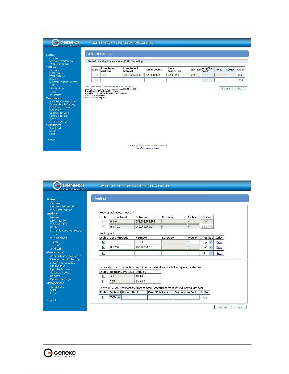
USER MANUAL
4Gon www.4Gon.co.uk info@4gon.co.uk Tel: +44 (0)1245 808295 Fax: +44 (0)1245 808299
• Configure GRE Route. Click Routing on Settings Tab. Parameters for this example are:
GWR Series Router
F
igure 79 - GRE configuration page
- Destination Network: 10.2.2.0
- Netmask: 255.255.255.0
F
igure 80 - Routing configuration page
• Optionally configure IP Filtering and TCP service port settings to block any unwanted incoming
traffic.
User from remote LAN should be able to communicate with HQ LAN.
77
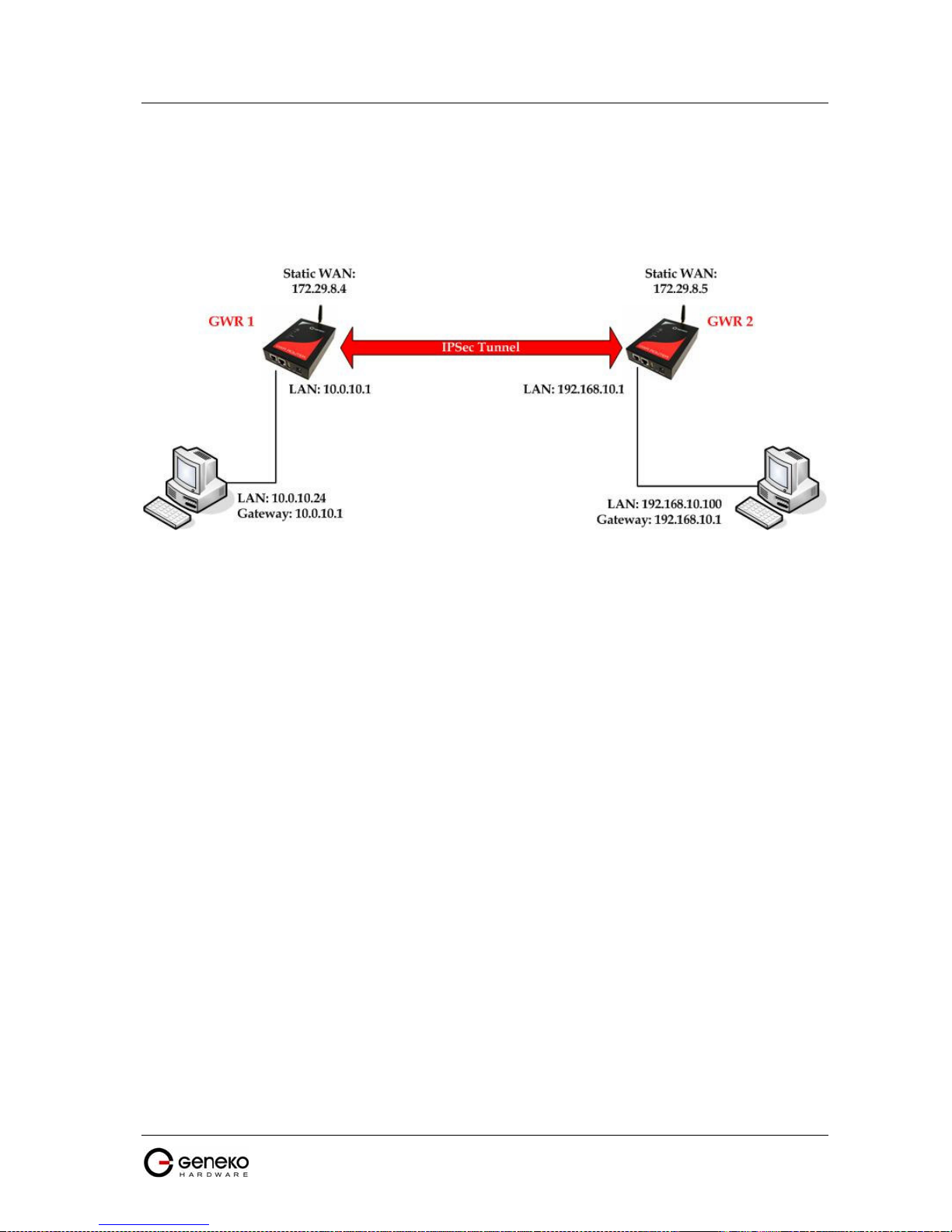
USER MANUAL
4Gon www.4Gon.co.uk info@4gon.co.uk Tel: +44 (0)1245 808295 Fax: +44 (0)1245 808299
GWR Series Router
IPSec Tunnel configuration between two GWR Routers
IPSec tunnel is a type of a VPN tunnels with a secure
Figure 81 is illustrated simple network with two GWR Routers. Idea is to create IPSec tunnel for LAN to
LAN (site to site) connectivity.
F
igure 81 - IPSec tunnel between two GWR Routers
tunneling method. On the diagram below
The GWR Routers requirements:
• Static IP WAN address for tunnel source and tunnel destination address;
• Source tunnel address should have static WAN IP address;
• Destination tunnel address should have static WAN IP address;
GSM/UMTS APN Type: For GSM/UMTS networks GWR Router connections may require a
Custom APN. A Custom APN allows for various IP addressing options, particularly static IP addresses,
which are needed for most VPN connections. A custom APN should also support mobile terminated data
that may be required in most site-to-site VPNs.
The GWR Router 1 configuration:
• Click Network Tab, to open the LAN NETWORK screen. Use this screen to configure LAN
TCP/IP settings. Configure IP address and Netmask.
- IP Address: 10.0.10.1
- Subnet Mask: 255.255.255.0
- Press Save to accept the changes.
78
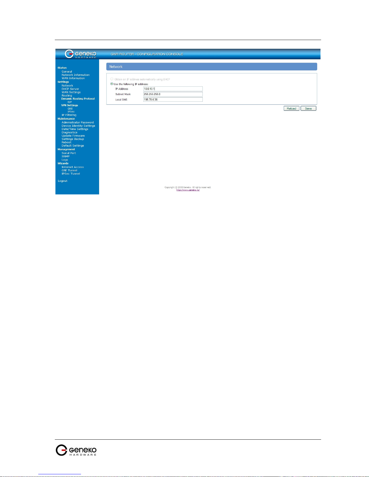
USER MANUAL
4Gon www.4Gon.co.uk info@4gon.co.uk Tel: +44 (0)1245 808295 Fax: +44 (0)1245 808299
GWR Series Router
F
igure 82 - Network configuration page for GWR Router 1
• Use SIM card with a static IP address, obtained from Mobile Operator.
• Click WAN Settings Tab to configure parameters necessary for GSM/UMTS connection. All
parameters necessary for connection configuration should be required from mobile operator.
• Check the status of GSM/UMTS connection (WAN Settings Tab). If disconnected please click
Connect button.
• Click VPN Settings > IPSEC to configure IPSEC tunnel parameters. Click Add New Tunnel
button to create new IPSec tunnel. Tunnel parameters are:
• Add New Tunnel
- Tunnel Name: test
- Enable: true
• Local Group Setup
- Local Security Gateway Type: IP Only
- IP Address: 172.29.8.4
- Local Security Group Type: IP
- IP Address: 10.0.10.1
• Remote Group Setup
- Remote Security Gateway Type: IP Only
- IP Address: 172.29.8.5
- Remote Security Group Type: IP
- IP Address: 192.168.10.1
• IPSec Setup
- Keying Mode: IKE with Preshared key
- Phase 1 DH group: Group 1
- Phase 1 Encryption: DES
- Phase 1 Authentication: MD5
- Phase 1 SA Life Time: 28800
- Perfect Forward Secrecy: true
- Phase 2 DH group: Group 1
- Phase 2 Encryption: DES
- Phase 2 Authentication: MD5
- Phase 2 SA Life Time: 3600
- Preshared Key: 1234567890
79

USER MANUAL
4Gon www.4Gon.co.uk info@4gon.co.uk Tel: +44 (0)1245 808295 Fax: +44 (0)1245 808299
• Advanced
GWR Series Router
- Aggressive Mode: true
- Compress(Support IP Payload Compression Protocol(IPComp)): false
- Dead Peer Detection(DPD): false
- NAT Traversal: true
- Press Save to accept the changes.
F
igure 83 - IPSEC configuration page I for GWR Router 1
Figure 84 - IPSec configuration page II for GWR Router 1
80

USER MANUAL
4Gon www.4Gon.co.uk info@4gon.co.uk Tel: +44 (0)1245 808295 Fax: +44 (0)1245 808299
- Click Start button on Internet Protocol Security page to initiate IPSEC tunnel.
GWR Series Router
F
igure 85 – IPSec start/stop page for GWR Router 1
• On the device connected on GWR router 1 setup default gateway 10.0.10.1
The GWR Router 2 configuration:
• Click Network Tab, to open the LAN NETWORK screen. Use this screen to configure LAN
TCP/IP settings. Configure IP address and Netmask.
- IP Address: 192.168.10.1
- Subnet Mask: 255.255.255.0
- Press Save to accept the changes.
81

USER MANUAL
4Gon www.4Gon.co.uk info@4gon.co.uk Tel: +44 (0)1245 808295 Fax: +44 (0)1245 808299
GWR Series Router
F
igure 86 - Network configuration page for GWR Router 2
• Use SIM card with a static IP address, obtained from Mobile Operator.
• Click WAN Settings Tab to configure parameters necessary for GSM/UMTS connection. All
parameters necessary for connection configuration should be required from mobile operator.
• Check the status of GSM/UMTS connection (WAN Settings Tab). If disconnected please click
Connect button.
• Click VPN Settings > IPSEC to configure IPSEC tunnel parameters. Click Add New Tunnel
button to create new IPSec tunnel. Tunnel parameters are:
• Add New Tunnel
- Tunnel Name: test
- Enable: true
• Local Group Setup
- Local Security Gateway Type: IP Only
- IP Address: 172.29.8.5
- Local Security Group Type: IP
- IP Address: 192.168.10.1
• Remote Group Setup
- Remote Security Gateway Type: IP Only
- IP Address: 172.29.8.4
- Remote Security Group Type: IP
- IP Address: 10.0.10.1
• IPSec Setup
- Keying Mode: IKE with Preshared key
- Phase 1 DH group: Group 1
- Phase 1 Encryption: DES
- Phase 1 Authentication: MD5
- Phase 1 SA Life Time: 28800
- Perfect Forward Secrecy: true
- Phase 2 DH group: Group 1
- Phase 2 Encryption: DES
- Phase 2 Authentication: MD5
82

USER MANUAL
4Gon www.4Gon.co.uk info@4gon.co.uk Tel: +44 (0)1245 808295 Fax: +44 (0)1245 808299
• Advanced
GWR Series Router
- Phase 2 SA Life Time: 3600
- Preshared Key: 1234567890
- Aggressive Mode: true
- Compress(Support IP Payload Compression Protocol(IPComp)): false
- Dead Peer Detection(DPD): false
- NAT Traversal: true
- Press Save to accept the changes.
F
igure 87 - IPSEC configuration page I for GWR Router 2
Figure 88 - IPSec configuration page II for GWR Router 2
83

USER MANUAL
4Gon www.4Gon.co.uk info@4gon.co.uk Tel: +44 (0)1245 808295 Fax: +44 (0)1245 808299
- Click Start button on Internet Protocol Security page to initiate IPSEC tunnel.
GWR Series Router
F
igure 89 – IPSec start/stop page for GWR Router 2
• On the device connected on GWR router 2 setup default gateway 192.168.10.1.
84

USER MANUAL
4Gon www.4Gon.co.uk info@4gon.co.uk Tel: +44 (0)1245 808295 Fax: +44 (0)1245 808299
GWR Series Router
IPSec Tunnel configuration between GWR Router and Cisco Router
IPSec tunnel is a type of a VPN tunnels with a secure
Figure 90 is illustrated simple network with GWR Router and Cisco Router. Idea is to create IPSec tunnel
for LAN to LAN (site to site) connectivity.
tunneling method. On the diagram below
F
igure 90 - IPSec tunnel between GWR Router and Cisco Router
The GWR Routers requirements:
• Static IP WAN address for tunnel source and tunnel destination address;
• Source tunnel address should have static WAN IP address;
• Destination tunnel address should have static WAN IP address;
GSM/UMTS APN Type: For GSM/UMTS networks GWR Router connections may require a
Custom APN. A Custom APN allows for various IP addressing options, particularly static IP addresses,
which are needed for most VPN connections. A custom APN should also support mobile terminated data
that may be required in most site-to-site VPNs.
The GWR Router configuration:
• Click Network Tab, to open the LAN NETWORK screen. Use this screen to configure LAN
TCP/IP settings. Configure IP address and Netmask.
- IP Address: 192.168.10.1
- Subnet Mask: 255.255.255.0
- Press Save to accept the changes.
85

USER MANUAL
4Gon www.4Gon.co.uk info@4gon.co.uk Tel: +44 (0)1245 808295 Fax: +44 (0)1245 808299
GWR Series Router
F
igure 91 - Network configuration page for GWR Router
• Use SIM card with a static IP address, obtained from Mobile Operator.
• Click WAN Settings Tab to configure parameters necessary for GSM/UMTS connection. All
parameters necessary for connection configuration should be required from mobile operator.
• Check the status of GSM/UMTS connection (WAN Settings Tab). If disconnected please click
Connect button.
• Click VPN Settings > IPSEC to configure IPSEC tunnel parameters. Click Add New Tunnel
button to create new IPSec tunnel. Tunnel parameters are:
• Add New Tunnel
- Tunnel Name: test
- Enable: true
• Local Group Setup
- Local Security Gateway Type: IP Only
- IP Address: 172.30.147.96
- Local Security Group Type: Subnet
- IP Address: 192.168.10.0
- Subnet Mask: 255.255.255.0
• Remote Group Setup
- Remote Security Gateway Type: IP Only
- IP Address: 150.160.170.1
- Remote Security Group Type: IP
- IP Address: 10.10.10.0
- Subnet Mask: 255.255.255.0
• IPSec Setup
- Keying Mode: IKE with Preshared key
- Phase 1 DH group: Group 2
- Phase 1 Encryption: 3DES
- Phase 1 Authentication: SHA1
- Phase 1 SA Life Time: 28800
- Perfect Forward Secrecy: true
- Phase 2 DH group: Group 2
86

USER MANUAL
4Gon www.4Gon.co.uk info@4gon.co.uk Tel: +44 (0)1245 808295 Fax: +44 (0)1245 808299
• Advanced
GWR Series Router
- Phase 2 Encryption: 3DES
- Phase 2 Authentication: SHA1
- Phase 2 SA Life Time: 3600
- Preshared Key: 1234567890
- Aggressive Mode: true
- Compress(Support IP Payload Compression Protocol(IPComp)): false
- Dead Peer Detection(DPD): false
- NAT Traversal: true
- Press Save to accept the changes.
-
F
igure 92 - IPSEC configuration page I for GWR Router
87

USER MANUAL
4Gon www.4Gon.co.uk info@4gon.co.uk Tel: +44 (0)1245 808295 Fax: +44 (0)1245 808299
GWR Series Router
F
igure 93 - IPSec configuration page II for GWR Router
- Click Start button on Internet Protocol Security page to initiate IPSEC tunnel.
F
igure 94 – IPSec start/stop page for GWR Router
• On the device connected on GWR router setup default gateway 192.168.10.1.
88

USER MANUAL
4Gon www.4Gon.co.uk info@4gon.co.uk Tel: +44 (0)1245 808295 Fax: +44 (0)1245 808299
GWR Series Router
The Cisco Router configuration:
version 12.4
se
rvice timestamps debug datetime msec
service timestamps log datetime msec
no service password-encryption
!
hostname Cisco-Router
!
boot-start-marker
boot-end-marker
!
username admin password 7 ****************
!
enable secret 5 *********************
!
no aaa new-model
!
no ip domain lookup
!
!--- Keyring that defines wildcard pre-shared key.
!
crypto keyring remote
pre-shared-key address 0.0.0.0 0.0.0.0 key 1234567890
!
!--- ISAKMP policy
!
crypto isakmp policy 10
encr 3des
authentication pre-share
group 2
lifetime 28800
!
!--- Profile for LAN-to-LAN connection, that references
!--- the wildcard pre-shared key and a wildcard identity
!
crypto isakmp profile L2L
description LAN to LAN vpn connection
keyring remote
match identity address 0.0.0.0
!
!
crypto ipsec transform-set testGWR esp-3des esp-sha-hmac
!
!--- Instances of the dynamic crypto map
!--- reference previous IPsec profile.
!
crypto dynamic-map dynGWR 5
set transform-set testGWR
set isakmp-profile L2L
!
!--- Crypto-map only references instances of the previous dynamic crypto map.
!
crypto map GWR 10 ipsec-isakmp dynamic dynGWR
!
interface FastEthernet0/0
description WAN INTERFACE
ip address 150.160.170.1 255.255.255.252
ip nat outside
no ip route-cache
no ip mroute-cache
duplex auto
speed auto
crypto map GWR
!
interface FastEthernet0/1
description LAN INTERFACE
ip address 10.10.10.1 255.255.255.0
ip nat inside
no ip route-cache
no ip mroute-cache
duplex auto
speed auto
!
ip route 0.0.0.0 0.0.0.0 150.160.170.2
89

USER MANUAL
4Gon www.4Gon.co.uk info@4gon.co.uk Tel: +44 (0)1245 808295 Fax: +44 (0)1245 808299
!
ip http server
no ip http secure-server
ip nat inside source list nat_list interface FastEthernet0/0 overload
!
ip access-list extended nat_list
deny ip 10.10.10.0 0.0.0.255 192.168.10.0 0.0.0.255
permit ip 10.10.10.0 0.0.0.255 any
!
access-list 23 permit any
!
line con 0
line aux 0
line vty 0 4
access-class 23 in
privilege level 15
login local
transport input telnet ssh
line vty 5 15
access-class 23 in
privilege level 15
login local
transport input telnet ssh
!
end
GWR Series Router
Use this section to confirm that your configuration works properly. Debug commands that run on the
Cisco router can confirm that the correct parameters are matched for the remote connections.
show ip interface—Displays the IP address assignment to the spoke router.
show crypto isakmp sa detail—Displays the IKE SAs, which have been set-up between the IPsec
initiators.
show crypto ipsec sa—Displays the IPsec SAs, which have been set-up between the IPsec
initiators.
debug crypto isakmp—Displays messages about Internet Key Exchange (IKE) events.
debug crypto ipsec—Displays IPsec events.
debug crypto engine—Displays crypto engine events.
90

USER MANUAL
4Gon www.4Gon.co.uk info@4gon.co.uk Tel: +44 (0)1245 808295 Fax: +44 (0)1245 808299
GWR Series Router
IPSec Tunnel configuration between GWR Router and Juniper SSG firewall
IPSec tunnel is a type of a VPN tunnels with a secure
tunneling method. On the diagram below
Figure 95 is illustrated simple network with GWR Router and Cisco Router. Idea is to create IPSec tunnel
for LAN to LAN (site to site) connectivity.
F
igure 95 - IPSec tunnel between GWR Router and Cisco Router
The GWR Routers requirements:
• Static IP WAN address for tunnel source and tunnel destination address;
• Source tunnel address should have static WAN IP address;
• Destination tunnel address should have static WAN IP address;
GSM/UMTS APN Type: For GSM/UMTS networks GWR Router connections may require a
Custom APN. A Custom APN allows for various IP addressing options, particularly static IP addresses,
which are needed for most VPN connections. A custom APN should also support mobile terminated data
that may be required in most site-to-site VPNs.
The GWR Router configuration:
• Click Network Tab, to open the LAN NETWORK screen. Use this screen to configure LAN
TCP/IP settings. Configure IP address and Netmask.
- IP Address: 192.168.10.1
- Subnet Mask: 255.255.255.0
- Press Save to accept the changes.
91

USER MANUAL
4Gon www.4Gon.co.uk info@4gon.co.uk Tel: +44 (0)1245 808295 Fax: +44 (0)1245 808299
GWR Series Router
F
igure 96 - Network configuration page for GWR Router
• Use SIM card with a static IP address, obtained from Mobile Operator.
• Click WAN Settings Tab to configure parameters necessary for GSM/UMTS connection. All
parameters necessary for connection configuration should be required from mobile operator.
• Check the status of GSM/UMTS connection (WAN Settings Tab). If disconnected please click
Connect button.
• Click VPN Settings > IPSEC to configure IPSEC tunnel parameters. Click Add New Tunnel
button to create new IPSec tunnel. Tunnel parameters are:
• Add New Tunnel
- Tunnel Name: test
- Enable: true
• Local Group Setup
- Local Security Gateway Type: IP Only
- IP Address: 172.30.147.96
- Local Security Group Type: Subnet
- IP Address: 192.168.10.0
- Subnet Mask: 255.255.255.0
• Remote Group Setup
- Remote Security Gateway Type: IP Only
- IP Address: 150.160.170.1
- Remote Security Group Type: IP
- IP Address: 10.10.10.0
- Subnet Mask: 255.255.255.0
• IPSec Setup
- Keying Mode: IKE with Preshared key
- Phase 1 DH group: Group 2
- Phase 1 Encryption: 3DES
- Phase 1 Authentication: SHA1
- Phase 1 SA Life Time: 28800
- Perfect Forward Secrecy: true
- Phase 2 DH group: Group 2
92
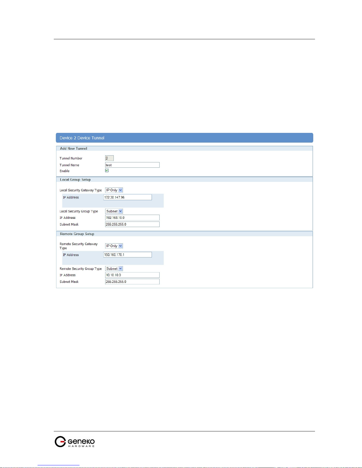
USER MANUAL
4Gon www.4Gon.co.uk info@4gon.co.uk Tel: +44 (0)1245 808295 Fax: +44 (0)1245 808299
• Advanced
GWR Series Router
- Phase 2 Encryption: 3DES
- Phase 2 Authentication: SHA1
- Phase 2 SA Life Time: 3600
- Preshared Key: 1234567890
- Aggressive Mode: true
- Compress(Support IP Payload Compression Protocol(IPComp)): false
- Dead Peer Detection(DPD): false
- NAT Traversal: true
- Press Save to accept the changes.
F
igure 97 - IPSEC configuration page I for GWR Router
93
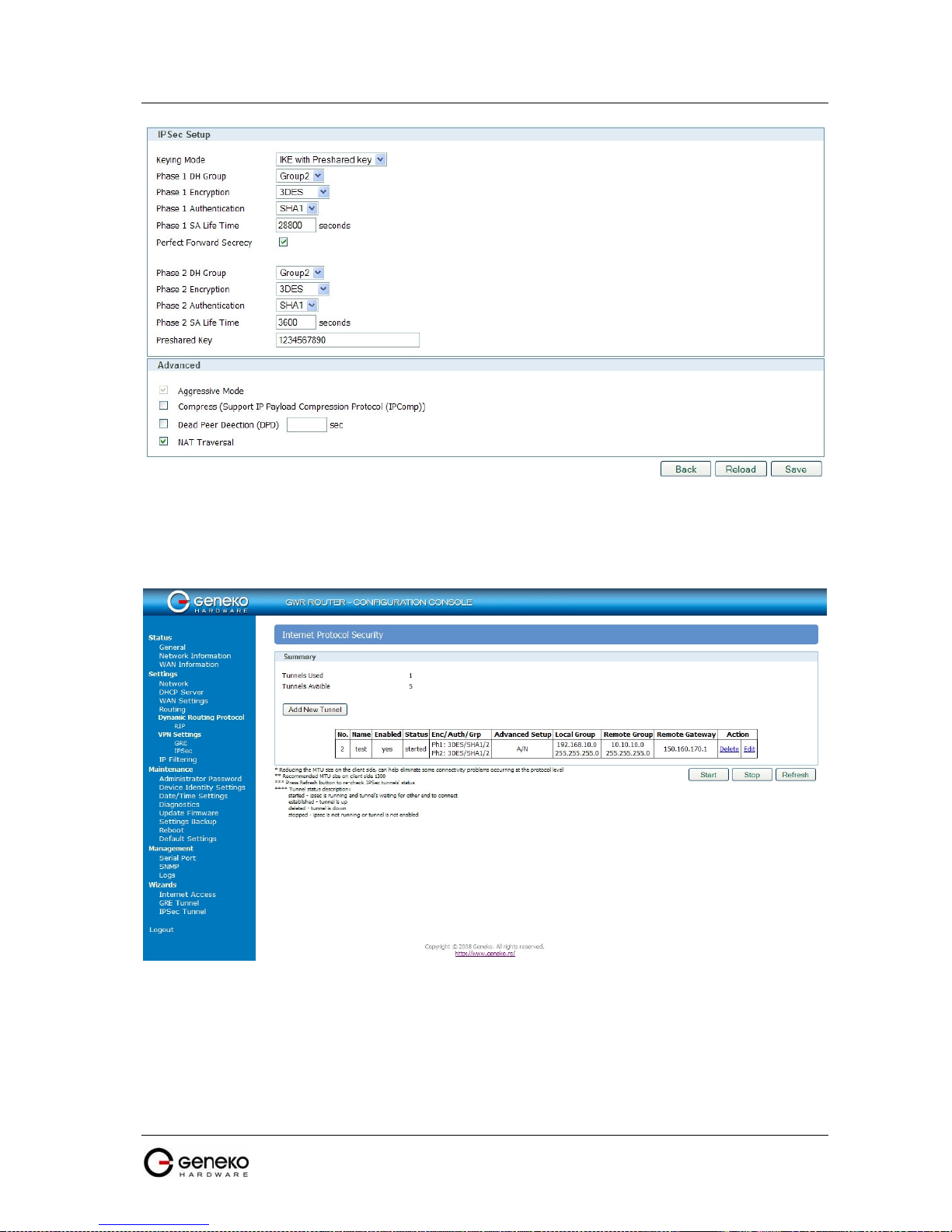
USER MANUAL
4Gon www.4Gon.co.uk info@4gon.co.uk Tel: +44 (0)1245 808295 Fax: +44 (0)1245 808299
GWR Series Router
F
igure 98 - IPSec configuration page II for GWR Router
- Click Start button on Internet Protocol Security page to initiate IPSEC tunnel.
F
igure 99 – IPSec start/stop page for GWR Router
• On the device connected on GWR router setup default gateway 192.168.10.1.
94
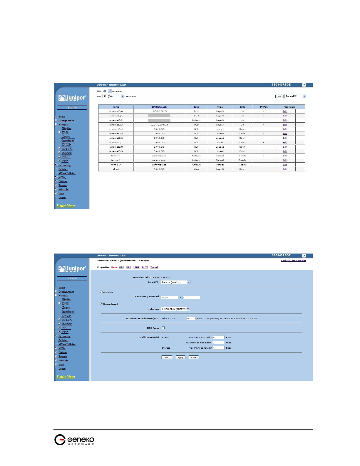
USER MANUAL
4Gon www.4Gon.co.uk info@4gon.co.uk Tel: +44 (0)1245 808295 Fax: +44 (0)1245 808299
GWR Series Router
The Juniper SSG firewall configuration:
Step1 – Create New Tunnel Interface
• Click Interfaces on Network Tab.
F
igure 100 - Network Interfaces (list)
• Bind New tunnel interface to Untrust interface (outside int – with public IP addresss).
• Use unnumbered optuion for IP address configuration.
F
igure 101 - Network Interfaces (edit)
95

USER MANUAL
4Gon www.4Gon.co.uk info@4gon.co.uk Tel: +44 (0)1245 808295 Fax: +44 (0)1245 808299
GWR Series Router
Step 2 - Create New VPN IPSEC tunnel
• Click VPNs in main menu. To create new gateway click Gateway on AutoKey Advanced tab.
F
igure 102 - AutoKey Advanced Gateway
• Click New button. Enter gateway parameters:
- Gateway name: TestGWR
- Security level: Custom
- Remote Gateway type: Dynamic IP address( because your GWR router are hidden behind
Mobile operator router’s (firewall) NAT)
- Peer ID: 172.30.147.96
- Presharedkey: 1234567890
- Local ID: 150.160.170.1
96

USER MANUAL
4Gon www.4Gon.co.uk info@4gon.co.uk Tel: +44 (0)1245 808295 Fax: +44 (0)1245 808299
GWR Series Router
• Click Advanced button.
- Security level – User Defined: custom
- Phase 1 proposal: pre-g2-3des-sha
- Mode: Agressive(must be aggressive because of NAT)
- Nat-Traversal: enabled
- Click Return and OK.
F
igure 103 - Gateway parameters
97

USER MANUAL
4Gon www.4Gon.co.uk info@4gon.co.uk Tel: +44 (0)1245 808295 Fax: +44 (0)1245 808299
GWR Series Router
Step 3 - Create AutoKey IKE
• Click VPNs in main menu. Click AutoKey IKE.
• Click New button.
F
igure 104 - Gateway advanced parameters
98

USER MANUAL
4Gon www.4Gon.co.uk info@4gon.co.uk Tel: +44 (0)1245 808295 Fax: +44 (0)1245 808299
GWR Series Router
AutoKey IKE parameters are:
- VPNname: TestGWR
- Security level: Custom
- Remote Gateway: Predefined
- Choose VPN Gateway from step 2
F
igure 105 - AutoKey IKE
99

USER MANUAL
4Gon www.4Gon.co.uk info@4gon.co.uk Tel: +44 (0)1245 808295 Fax: +44 (0)1245 808299
GWR Series Router
• Click Advanced button.
- Security level - User defined: custom
- Phase 2 proposal: pre-g2-3des-sha
- Bind to - Tunnel interface: tunnel.3(from step 1)
- Proxy ID: Enabled
- LocalIP/netmask: 10.10.10.0/24
- RemoteIP/netmask: 192.168.10.0/24
- Click Return and OK.
F
igure 106 - AutoKey IKE parameters
100
 Loading...