

Page 1
®
150
GENEE TECHNOLOGIES
INDIA PRIVATE LIMITED
An ISO 9001:2008 certied company
Classroom for the Future
WWW
@
Tel: 0124-4934500
Fax: 0124-4934521
Email: [email protected]
Website: www.genee-india.com, www.geneeworld.com
Plot No. 698, Udyog Vihar, Phase V, Gurgaon, Haryana-122016, India
User manual
®
150
Classroom for the Future
Page 2

2
To prevent fire or shock hazard, do not expose the unit to rain or
moisture.
To prevent electrical shock, do not open the unit. Refer to qualified
personnel for service only.
Do not use the unit continuously for more than 24 hours with camera
auto focus on. It may cause damage to the camera lens.
Be careful not to spill water or other liquids onto the unit, or allow
combustible or metallic objects to get inside the base.
Unplug the visualiser from the wall outlet when it is not being used for
a long period of time.
Clean the unit with a soft cloth lightly moistened with a mild detergent
solution.
Clean the lens carefully with an air spray or soft dry cloth to avoid
scratching it.
Rotate the camera lens cap before power the unit on.
Please follow these precautions:
PRECAUTIONS
3
Product Introduction ....................................................................4
Parts Identification ........................................................ ...............4
Making Adjustments......................................................................5
Control Panel ..............................................................................8
Remote Control Instruction ............................................................9
Installing visualiser software ........................................................10
USB PORT ................................................................................11
USB Image Capture ....................................................................12
Specification..............................................................................13
Contents
Page 3
5
Making Adjustments
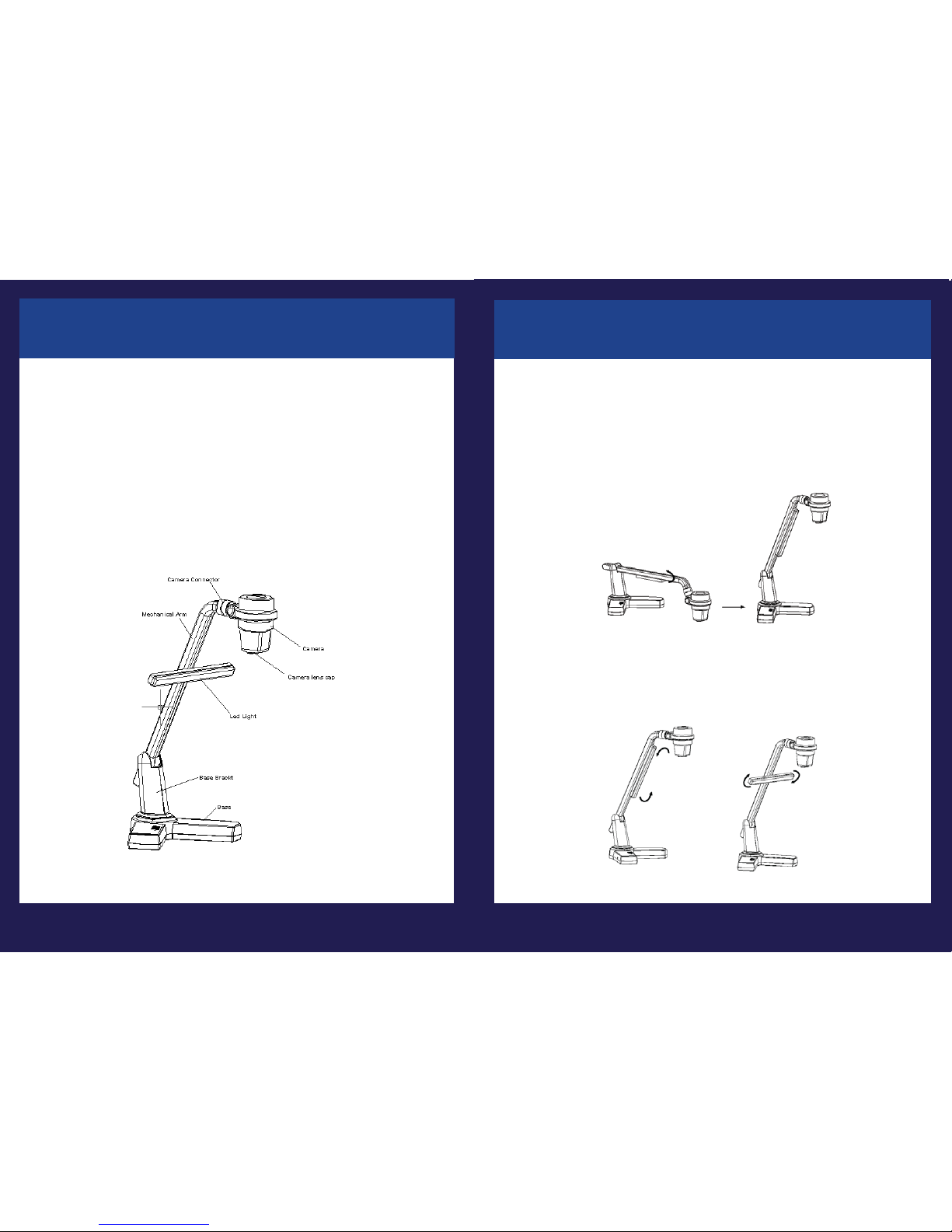
Onthe visualiser, there are six places can be adjusted.
1. Adjust Mechanical Arm
This adjustment can increase and decrease image. Hold the visualiser base
with one hand, carry the mechanical arm with another hand and adjust it up
and down. The mechanical arm can be moved from almost any angle.
2. Adjust LED light
The LED light can be rotated 90 degrees. (as blow illustration)
4
Parts Identification
Thank you for purchasing the visualiser. This visualiser comes with a new
design which is more simple, flexible, portable and with a high resolution. The
visualiser can be used to present 3D objects, texts, graphs, transparencies and
negative films. It can be connected to projector, PC and other multi-media
equipments. The visualiser is not just a equipment in corporate environment
but also a indispensable tool to academic, medical and scientific community.
Product Introduction
Page 4
6
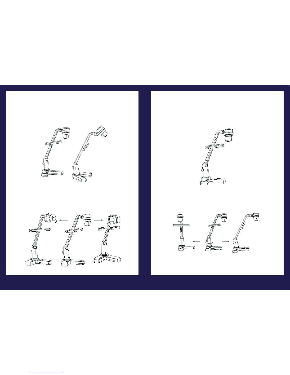
3. Adjust Camera Box
Hold the camera box and rotate it up and down. The camera box can be
rotated 45 degrees. (as below illustration)
Hold the camera box and rotate it left and right. The camera box can be
rotated 90 degrees. (as below illustration)
7
4. Adjust Camera Head
Hold the camera connector with one hand, rotate the camera box connector
with another hand. The camera head can be rotated 90 degrees. (as below
illustration)
5. Adjust Base Bracket
Hold the vislualizer base with one hand, rotate the base bracket with another
hand. The base bracket can be rotated 45 degrees. (as below illustration)
Notice: Do not rotate the parts emphatically when the rotation reached
maximum.
Page 5
8
Control Panel
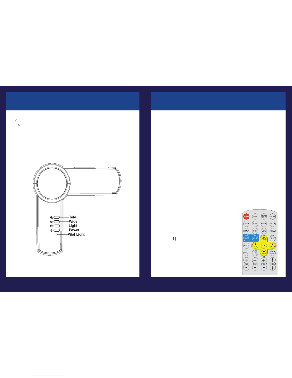
There are four touch buttons located on the top of visualiser base:
T : Enlarge image
·W : Reduce image
·LED Light: Turn the LED light on/off
·Power: Turn the visualiser on/off
·Pilot Light: On normal operations a blue color will be lit, in stand by mode the
color of the light will be red.
·
+
9
Remote Control Instruction
POWER (Control the visualiser On/Off)
SAVE (Save captured images)
RECALL (Multiple Screen Display)
LAMP (Control the arm lights)
ROTATE (Rotate the image)
FREEZE (Freeze the image)
NEG (Display film negatives)
MIRROR (V-Reverse the image)
XGA (Switch between XGA (1024 x 768) and SXGA (1280 x 1024) mode)
TEXT (Switch between image/text mode)
B&W (Switch between Color mode and Black & White mode)
TITLE (Freeze the top 1/8 of the screen)
SPLIT (Image Split function)
PROJECTOR POWER (No function)
PROJECTOR INPUT (No function)
EXIT (Exit selected function)
TELE/WIDE(Increase and decrease magnification)
FAR/NEAR (Focus near or far)
AUTO (To auto adjust brightness, auto white balance and auto focus)
CAM/PC1/PC2 (No function)
S-VIDEO/VIDEO (No function)
VOLUME+/- (No function)
RED+/- (Increase or decrease the red hue)
BLUE+/- (Increase or decrease the blue hue)
BRIGHT+/- (Increase or decrease the brightness)
SCROLL / (No function)
Page 6
10
Installing Visualiser Software
This function is to snap and display images with the USB interface, which
includes displaying static and dynamic pictures, snapping dynamic images
and playback the dynamic images with the Windows Media Player or its own
player.
Insert the CD-ROM that comes with the visualiser into the CD-ROM drive.
A. Click the Install Capture Program button to install the program that
captures images in the AVI or JPG format.
B. After the installation is finished, then click the Exit button to exit the
Software Setup window.
C. Shut down your computer when prompted in order for the changes to
take effect.
D. Use the USB2.0 cable provided to connect your computer to the
visualiser before your computer is restarted.
11
The USB port can be used to store still images from the visualiser in a computer. Connect the visualiser to your computer with the supplied USB cable. The
visualiser software is available on the supplied CD-ROM.
1. Computer hardware requirement: CPU: 2.4GHz, RAM: 256M or above,
Graphic card 64M, USB 2.0 port, Hard disk 40G or more, Monitor display
resolution higher than XGA (1024*768).
2. Operating system: Windows XP SP2 (Service Pack 2).
3. Must use a high-speed USB 2.0 cable provided
4. When connecting the visualiser to a desktop computer with the high-speed
USB 2.0 cable provided, we recommend using the USB port located on the
rear of the mainframe. The USB port on the front of the computer might have
interference.
USB PORT
* Please pay attention to the following:
Page 7

12
USB Image Capture
You can capture and control images on the visualiser from a computer
connected with a USB connector.
Click [Start] -> [Program] -> [VideoCap] -> “VideoCapx.xx” (x.xx is
software’s version) to open the software.
A. Static Images Snap
Click “Capture”—>“Capture Frame”, input the file name in dialog box, or you
can click icon on the toolbar, then input file name in dialog window. The
image file is JPG format.
B. Snap Video Stream
Click“Capture”—>“Start Capture”, input the file name in dialog box, or click
icon on the toolbar, then input the file name in dialog box. If you want to set
the time limit for the capture, select “Capture” ->“Set Time Limit“ to set the
time limit. Click “Start Capture” to start capture, and click “Stop Capture” or
icon on the toolbar to stop capture. (If you have set the time limit, it will stop
automatically when the time is up.) The video file is AVI format.
C. Set the Frame Rate
Click [Capture] -> [Set Frame Rate], and click open “Choose Frame Rate” to
set the frame rate.
D. Set Time Limit
Click [Capture] -> [Set Time Limit] to set the time limit while capturing video.
E. Note:
Do not connect / disconnect the USB cable when the application is running,
which will cause the program to be interrupted.
Specification
13
Pickup Device CMOS color sensor with 2.0 Mega Pixels
Output Resolution XGA(1024x768), SXGA(1280x 1024)
Zoom 4x optical, 10x digital
Focus Auto/manual
White Balance Auto/manual
Camera Head Rotation Horizontally 180°
Lens Rotation Vertically 180°
Negative/positive
conversion Yes
Black/white and color
selection Yes
Image Split Yes
Image Title Yes
Image Freeze Yes
Image Rotate 0°90°180°270°
Image Save & Recall 16 frames save, 4 x 4 multiple screen display
RGB Output DB15FLC x 1
USB port USB 2.0
Power Source 12V/4A external AC adapter
Lighting 3W LED lamps
Operating 0ºC~40ºC
Power AC 100~240V,50/60Hz
Dimensions (mm) Setup: 341x262x492mm
Weight 1.6kg
*Design and specifications are subject to change without notice.
 Loading...