

Page 1
Quick set up guide
Leaders in learning technology
Page 2

Quick set up guide for
Genee Vision 2100 visualiser
Page 3

Quick guide contents
Now that you have received your visualiser you will want to get started straight away.
Visualisers can be used independently through a direct connection to a projector or monitor screen,
or can be linked to a computer to integrate with software applications and interactive whiteboards.
Over the next few pages you will be shown how to connect and operate your visualiser.
1. Package contents
2. Connectivity identication
3. Connecting to a projector
4. Using the features
5. Switching projector inputs
6. Loading the software
7. FAQ & support
8. Operating positions
Page 4
1
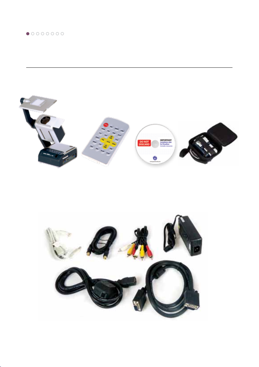
Package contents
Visualiser unit Remote control
(slotted into base of unit)
USB
A-A lead
IEC mains
cable
S-VHS
cable
Software CD Carry case
Composite A/V
phono cable
Power supply
adapter
VGA
male-male
Page 5
2
Connectivity identicationPackage contents
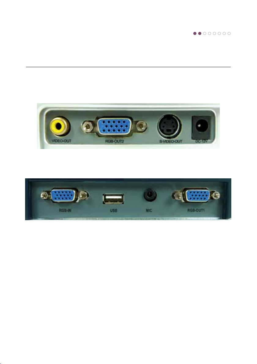
Rear panel
Side panel
VIDEO OUT / S-VIDEO OUT Visualiser video output
RGB OUT 1 / RGB OUT 2 RGB output (output the same signal)
DC-12V External 12V power adapter input connector
RGB-IN Laptop, computer or other RGB signal input
USB Computer image capture and video recording for both PC and Mac
Page 6
3
Connecting to a projector
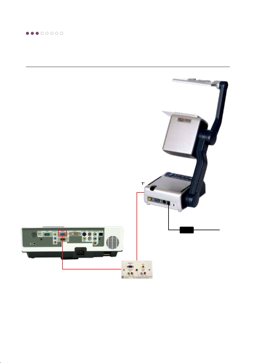
You can simply use your visualiser as a presentation
tool with a single (VGA) connection to a projector or
display screen:
‘RGB OUT’
socket
‘DC-12V’
socket
Projector
‘RGB in’
socket
VGA lead
(direct to projector,
screen or wall plate
socket)
You should now be able to see any 2D or 3D object placed under the camera, and use the built-in
functions.
Page 7
4
Using the features
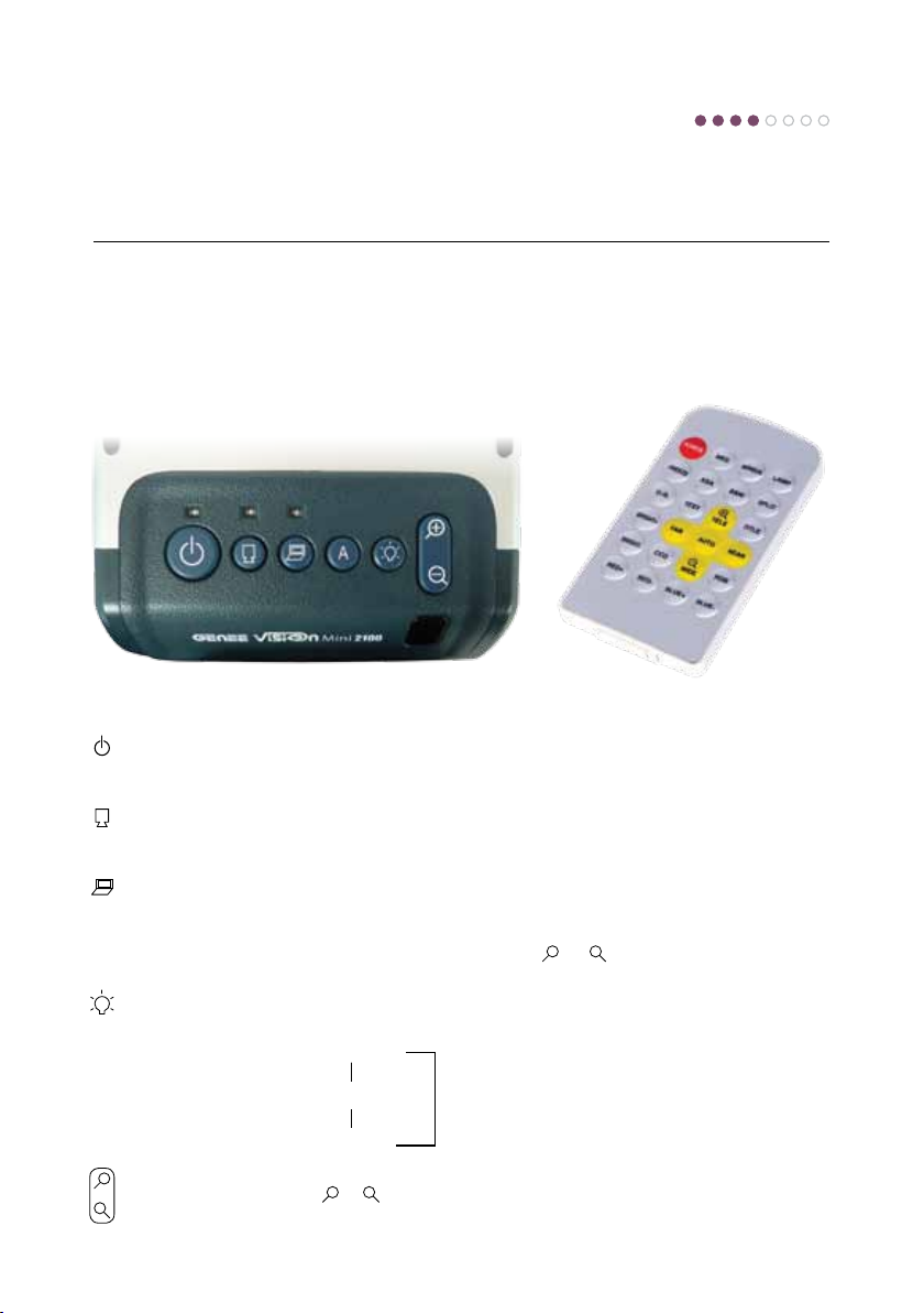
The visualisers have built-in functions that can be operated either from the control panel buttons or
from the remote control.
Button functions on the visualiser Button functions on the remote
Power Press the button once to power
Output visualiser Press the button, the RGB OUTPUT
signal button terminal outputs the visualiser
signal
Output computer Press the button, the RGB OUTPUT
signal button terminal outputs the computer
signal
Auto button Press the button to automatically
A
Light button Each time you press the button, the
+
Zoom button Press the
–
on the visualiser; press the button
again to power o the visualiser
adjust white balance and focus
lighting changes as below:
The body lights on
s
The slide holder back light on
s
All the lights o
–
+
or
button to zoom
in or zoom out
s
POWER Control the visualiser On/O
NEG Display negative image
MIRROR Reverse the image
LAMP Control the arm lights and
FREEZE Freeze the image
XGA Projector type
B&W Add and remove colour
SPLIT Image Split function
D./S. Switch between static mode
TEXT Sharpen image
+
T/W
TITLE Freeze the top 1/8 of the
FAR/NEAR Focus far or near
AUTO To auto adjust white balance
CCD/PC1/PC2 CCD/RGB input signal
RED + / - Alter colour balance
BLUE + / - Alter colour balance
BRIGHT+ / Adjust brightness of image
Remarks: Frz, Title, D./S. and Split
back light
and dynamic mode
–
Increase and decrease the
magnication
screen
and auto focus
selection
functions are only available on
PROJECTOR OUT port.
Page 8
5
Switching projector inputs
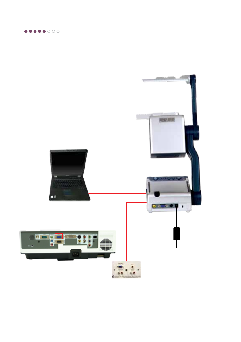
By linking your visualiser to a PC or laptop you can
switch projector inputs using the ‘camera’, ‘visualiser’
buttons on the unit’s control panel. This integrates
seamlessly with an interactive whiteboard and only
requires a second VGA lead (you may have to clone
the screen when linked to a laptop):
‘RGB IN’
socket
VGA lead
‘RGB in’
socket
Laptop
‘RGB OUT’
socket
‘12V IN’
socket
VGA lead
(direct to projector,
screen or wall plate
socket)
Projector
If your PC is connected to a splitter box, simply connect the VGA lead that comes from the wall-plate
socket into the visualiser’s ‘Projector’ socket, then use another VGA lead to link the splitter box to the
visualiser’s ‘Computer In’ socket. (The visualiser itself can be used as a splitter box!).
Page 9
Loading the software
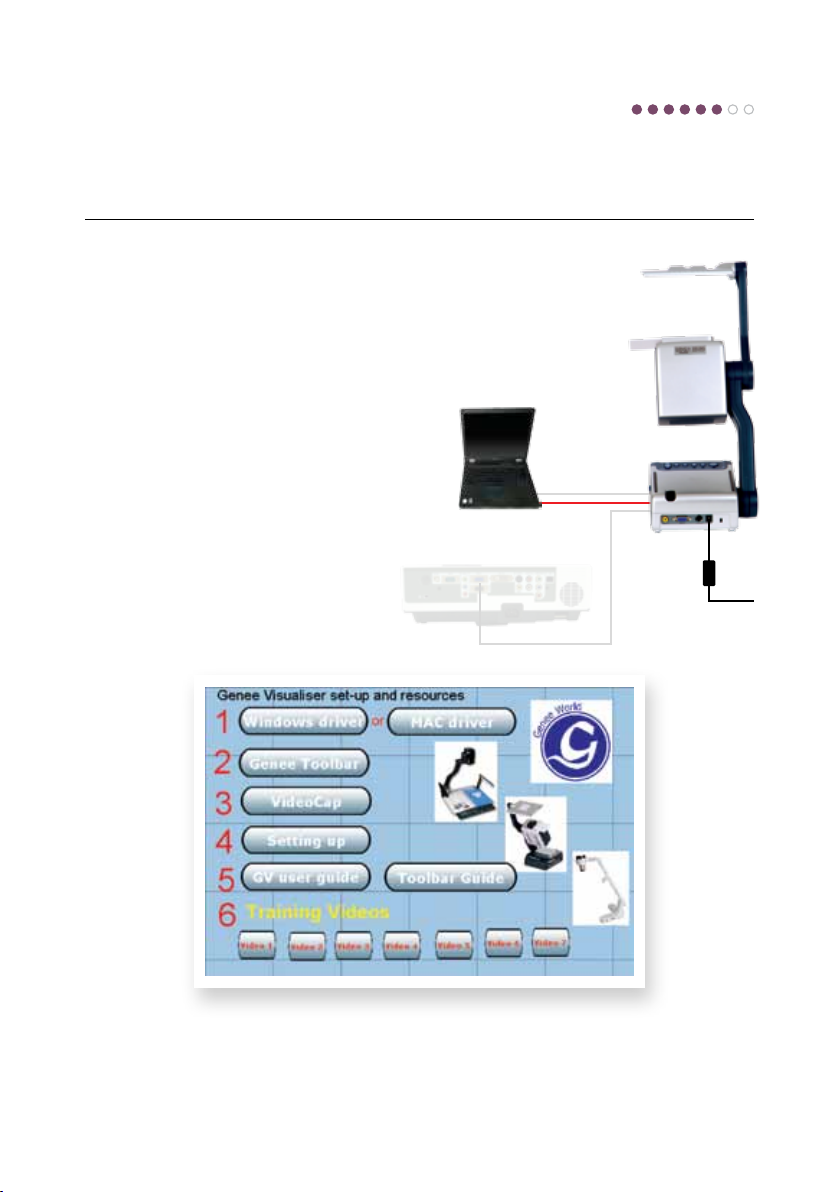
The accompanying disk has essential software
for enabling your computer to recognise the
visualiser and capture images, both still and
moving. This will be done through the USB
connecting lead.
The driver for your operating system must
be installed before connecting the USB lead.
The set-up wizard will take you through the
process.
VideoCap and Genee Toolbar are programs
that will give you live camera windows and
whiteboard tools on your desktop, allowing
you to annotate over them or capture in
common image and video formats that can
be incorporated into dierent applications.
USB lead
‘USB’
socket
6
The disk also contains additional information, including user guides and training videos.
Page 10

7
FAQ
1
I cannot get an image through the projector
i. Is the power connected and switched on (see step 3)?
ii. Have you opened the lens cover?
iii. Is the VGA lead connection from the projector plugged into the visualiser’s ‘projector’ socket?
2
How do I switch to my desktop image on my board?
i. Check that your VGA lead is connecting your visualiser to your computer (see step 3).
ii. Press the ‘output computer signal button’ (see step 4).
iii. Press the ‘output visualiser signal button’ to return to the visualiser.
3
How do I annotate over my visualiser images?
i. Check that the supplied VideoCap and/or Genee Toolbar has been installed.
ii. Check that the supplied USB lead is connecting the visualiser to your computer.
iii. Open either the VideoCap or Genee Toolbar software to get a live video window (you may
have to select the USB 2861 camera if there is a choice).
iv. You can now use your IWB tools or the Genee Toolbar tools to annotate over.
4
Will this work with any board?
Yes .
5
Can I save these images?
VideoCap and Genee Toolbar will save both still images and video images. You can also use
generic programs such as Microsoft MovieMaker or insert images directly onto Word pages, for
example, by going to the ‘insert from camera or scanner’ command.
Please contact [email protected] if the problem persists.
Support
Free technical helpline: 0870 386 1900 Option 4
Email: [email protected] Website: www.geneeworld.com
UK warranty: 5 years collect and return International warranty: available on request
Page 11
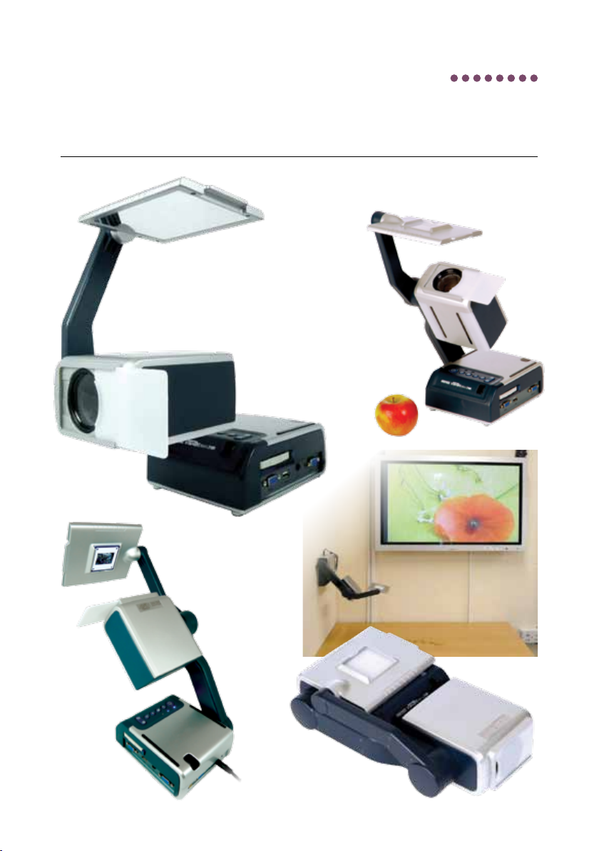
Operating positions
Viewing
Filming an
audience/
3D animation
an object
8
Viewing
a slide
Folded
Wall
mounted
Page 12

Leaders in learning technology
Genee World
PO Box 3256
Wolverhampton
WV3 0LA
 Loading...