

Page 1
Edificio Genebre. Av. de Joan Carles I, 46-48
08908 L'Hospitalet de Llobregat. Barcelona (Spain)
[email protected] - www.genebre.es
GENEBRE S.A. FECHA DE REVISIÓN: 09/03/2010 NUMERO DE REVISIÓN: 0
1
INSTALLATION, OPERATION
& MAINTENANCE MANUAL
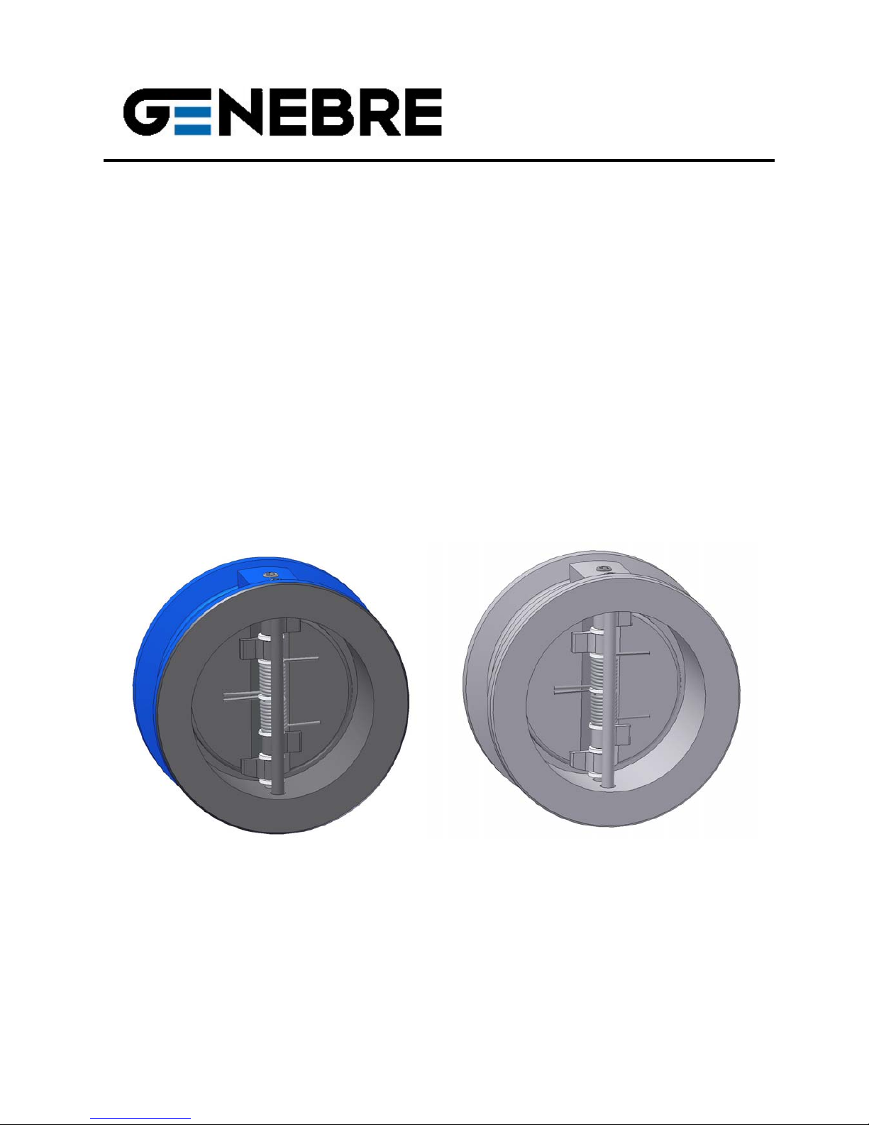
Double Disk Check Valve
Ref. GENEBRE: 2401 Ref. GENEBRE: 2402
Page 2

Edificio Genebre. Av. de Joan Carles I, 46-48
08908 L'Hospitalet de Llobregat. Barcelona (Spain)
[email protected] - www.genebre.es
GENEBRE S.A. FECHA DE REVISIÓN: 09/03/2010 NUMERO DE REVISIÓN: 0
2
INSTRUCTIONS FOR INSTALLATION, OPERATION & MAINTENANCE MANUAL
1. Spare parts ................................................................................................... 3
1.1 Parts list ........................................................................................................ 4
2. Storage ............................................................................................................4
3. Installation Instructions ............................................................................... 4
3.1 Preparation ................................................................................................ 4
3.2 Installation ................................................................................................... 5
4. Operating Instructions ……..........................................................………..6
4.1 Usage ......................................................................................................... 6
4.2 Operation ................................................................................................... 6
5. Maintenance Instructions ...........................................................................6
6. Repair Instructions .................................................................................... 6
6.1 Disassembly .................................................................................................. 6
6.2 Assembly ....................................................................................................... 7
7. Opening Pressure ………............................................................................ 7
8. Safety Instructions ....................................................................................... 8
Page 3
Edificio Genebre. Av. de Joan Carles I, 46-48
08908 L'Hospitalet de Llobregat. Barcelona (Spain)
[email protected] - www.genebre.es
GENEBRE S.A. FECHA DE REVISIÓN: 09/03/2010 NUMERO DE REVISIÓN: 0
3
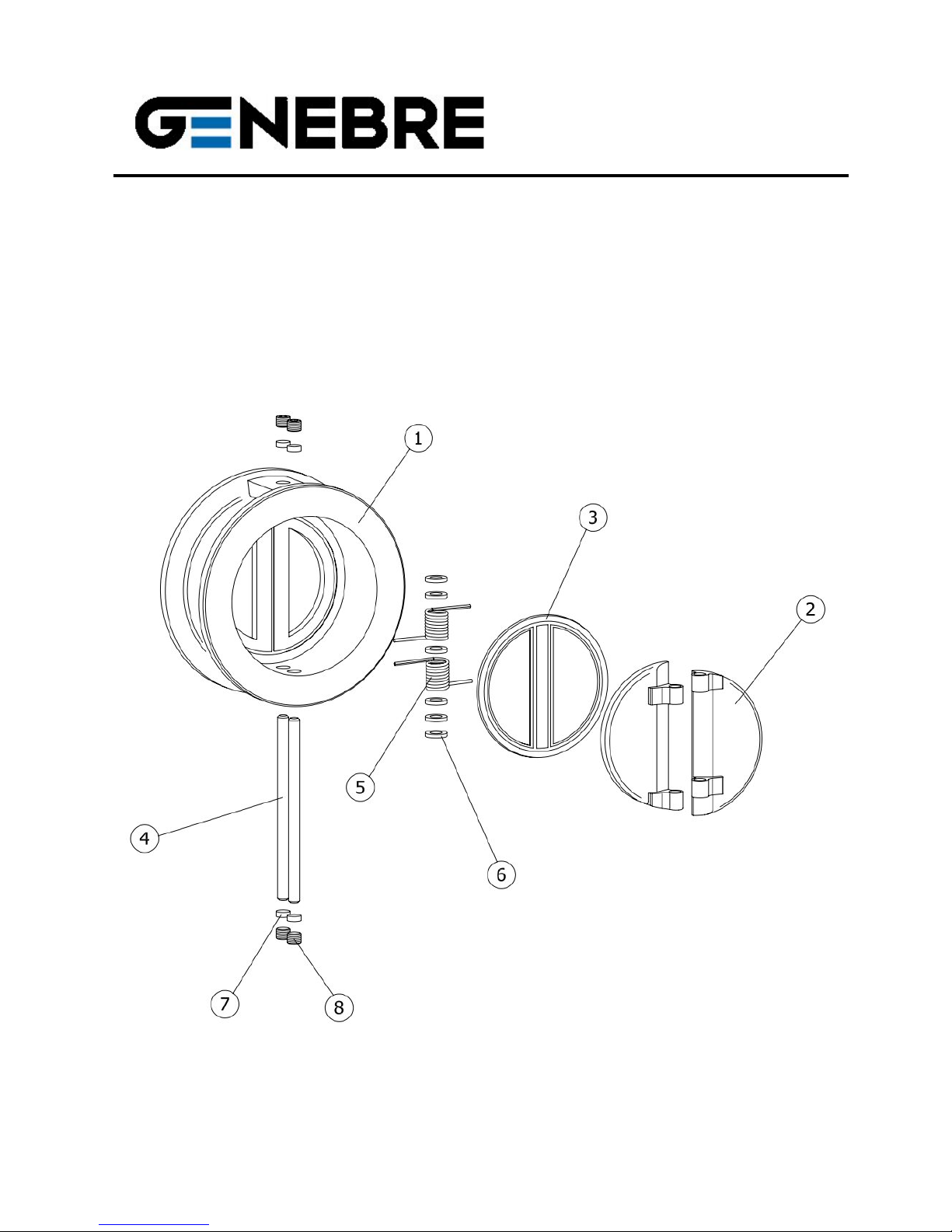
1) Spare Parts.
Page 4
Edificio Genebre. Av. de Joan Carles I, 46-48
08908 L'Hospitalet de Llobregat. Barcelona (Spain)
[email protected] - www.genebre.es
GENEBRE S.A. FECHA DE REVISIÓN: 09/03/2010 NUMERO DE REVISIÓN: 0
4
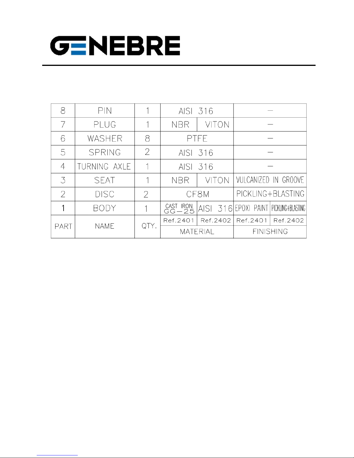
1.1) Parts List
2) Storage
In case that the valve is not installed immediately, keep it with protective packaging to
prevent strokes or accumulation of dirt (it should not be removed until the valve is going to be
installed). As far as possible, the valves should be stored in a dry and clean area.
3) Installation Instructions
3.1) Preparation
Remove any remaining packing materials from the valve.
There may be serious problems with any valve installed in a dirty pipe.
Make sure the pipe is free of dirt, welding particles, etc. before installation because the valve
could get irreparable damage when starting-up → prepare a clean working area.
Provide enough space for future maintenance.
Use flat gaskets between valve and pipe flanges to ensure sealing.
Page 5
Edificio Genebre. Av. de Joan Carles I, 46-48
08908 L'Hospitalet de Llobregat. Barcelona (Spain)
[email protected] - www.genebre.es
GENEBRE S.A. FECHA DE REVISIÓN: 09/03/2010 NUMERO DE REVISIÓN: 0
5
Check the correct operation of the valve by pushing both discs (part.2) in the flow direction
and noting that they return on their own once released. Otherwise, check that there are not
foreign objects inside the valve and then repeat the operation. If both discs can’t turn freely,
do not install the valve.
3.2) Installation
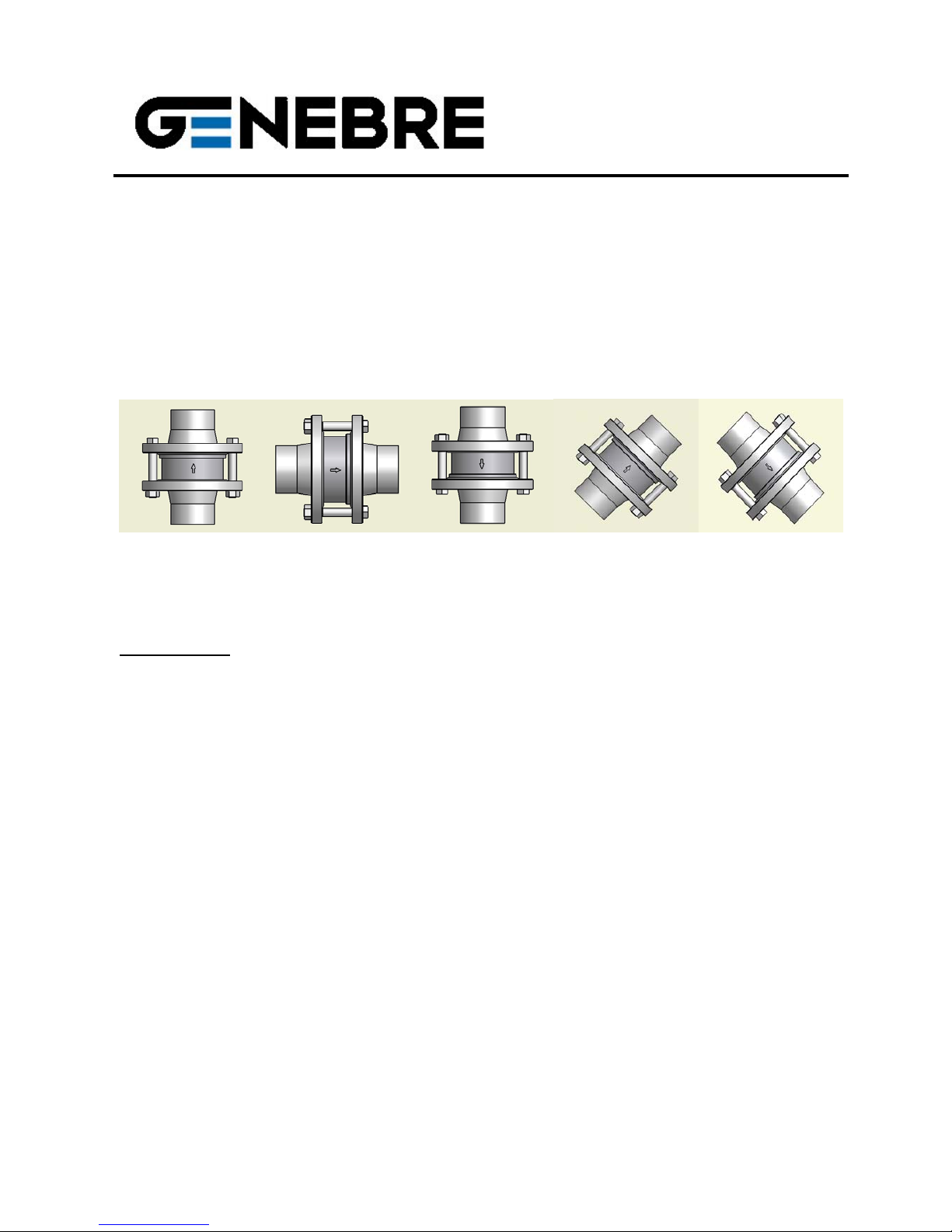
The double disk check valve can be installed in any position, but must take into account the
flow direction of the valve marked by an arrow in the body.
UPWARD HORIZONTAL DESCENDING INCLINED
ATTENTION: If you need to install the valve without spring, it may only be placed vertically
(upward flow).
IMPORTANT:
- Genebre double disk check valves are designed for mounting between flanges DIN
PN16 (art. 2401), DIN PN25 (art. 2402) and ANSI 150 (art. 2401 / art. 2402).
- Take the precaution of centring the valve with the axis of the pipe in order to ensure
sealing between body and flange.
- Do not weld with the valve mounted as it could get damage by overheating and
produce deformation of the seating area.
- Pay particular attention to the flow direction of the valve marked by an arrow in the
body.
- Check the parallelism of the flanges. Keep enough space between them so that the
valve can be inserted or removed easily.
- Tighten the screws of the flanges to hold the valve body firmly. Apply the alternate
clamping method to ensure proper installation.
- The valve should never be mounted adjacent to an elbow, reducer, valve or pump, to
avoid turbulence. The recommended minimum distance between these elements is 10
times the diameter of the pipe - upstream - and 3 times the diameter of the pipe downstream – according to CR 13932:2000.
Page 6

Edificio Genebre. Av. de Joan Carles I, 46-48
08908 L'Hospitalet de Llobregat. Barcelona (Spain)
[email protected] - www.genebre.es
GENEBRE S.A. FECHA DE REVISIÓN: 09/03/2010 NUMERO DE REVISIÓN: 0
6
4) Operating Instructions
4.1) Usage
Check valves are used mainly to prevent backward flow in the system. Wafer valves are
made for being installed between flanges, and provide a tight seal when are used respecting
the values of pressure / temperature for which they are designed.
The material of the valve body, seat and other components must be compatible with the fluid
going through the valve; otherwise the valve can be seriously damaged.
4.2) Operation
This type of valve, by definition, does not require any operation. Opening and closing is done
automatically depending on the pressure and flow direction. For more information about the
opening pressure of the valve consult the technical data sheet of the product.
5) Maintenance Instructions
Check valves do not require regular maintenance and lubrication during their life.
However, the following regular checks will help to extend the life of the valve and reduce
problems in the installation:
- keep the valve in the fully closed position.
- check that all screws and threaded unions are not loose or rusted. Tighten if necessary.
- Inspect the valve and surrounding areas to check that there is not any leakage.
6) Repair Instructions
If the valve is completely closed and the fluid is circulating through the line, the leakage is
due to the sealing surface and / or seat is damaged or due to an excessive wear of the
springs by fatigue after many cycles of continuous operation. In both cases it will be
necessary to take off the valve for repair. In this case Genebre, S.A. have springs available
(part. 5) for replacement. However, it could be the case (for ex. In remote areas) where, for
economical reasons, it is not advisable a valve repair, it is better to change the valve.
6.1) Disassembly
To make the repair it is necessary to remove the valve from the installation.
Page 7

Edificio Genebre. Av. de Joan Carles I, 46-48
08908 L'Hospitalet de Llobregat. Barcelona (Spain)
[email protected] - www.genebre.es
GENEBRE S.A. FECHA DE REVISIÓN: 09/03/2010 NUMERO DE REVISIÓN: 0
7
Make sure that the line is cold, drained and depressurized.
Prepare a clean working area and appropriate tooling for mechanical tasks.
a. - Loosen the bolts of the flanges, use a fixture if necessary.
b. - Remove the 4 screws (part. 8), the 4 rubber plugs (part. 7) and the 2 axles (part. 3).
c. - Separate the 2 springs (part. 5) and their washers (part. 6).
d. - Remove both disks (part. 2).
NOTE: The seat (part. 3) has been vulcanized into the groove during the manufacturing
process to improve their grip, so you can not remove it. Therefore, if damage has occurred to
the seat must replace the full valve.
6.2) Assembly
Before installing the valve again, make sure that the repair kit and / or parts are original ones.
a. - Clean the seat area inside the body (part. 1) and replace damaged or worn parts.
b. - Replace disks (part. 2) in its working position and take care that they have not been
damaged during the disassembling process. Continue with the springs (part. 5) and also with
the washers (part. 6).
c. - Insert both axles (part. 3) through their respective holes in the body taking care to guide
the disks, springs and washers. Then seal with the 4 plugs (part. 7) and insert back the 4 pin
(part. 8).
d. - Reinstall the valve between flanges. See Installation Instructions on page 4.
7) Opening Pressure
The double disk check valve (art. 2401 / art. 2402) has been designed to work with minimum
opening pressure (for details see technical data sheet of the product).
Page 8

Edificio Genebre. Av. de Joan Carles I, 46-48
08908 L'Hospitalet de Llobregat. Barcelona (Spain)
[email protected] - www.genebre.es
GENEBRE S.A. FECHA DE REVISIÓN: 09/03/2010 NUMERO DE REVISIÓN: 0
8
8) Safety Instructions
8.1) The fluids pass through a valve can be corrosive, toxic, flammable or pollutant. When
handling valves shall be taken necessary security measures and it is advisable to use
personal protective equipment:
1) Wear eye protection.
2) Wear gloves and appropriate work clothes.
3) Wear safety shoes.
4) Wear a helmet.
5) Note the availability of running water.
6) For flammable fluids, make sure you have a fire extinguisher.
8.2) Before removing a valve from a pipe, always check that the line is completely
cold, drained and depressurized.
8.3) Any valve that was used in toxic services must have a cleaning certificate before
handling.
 Loading...