

Page 1
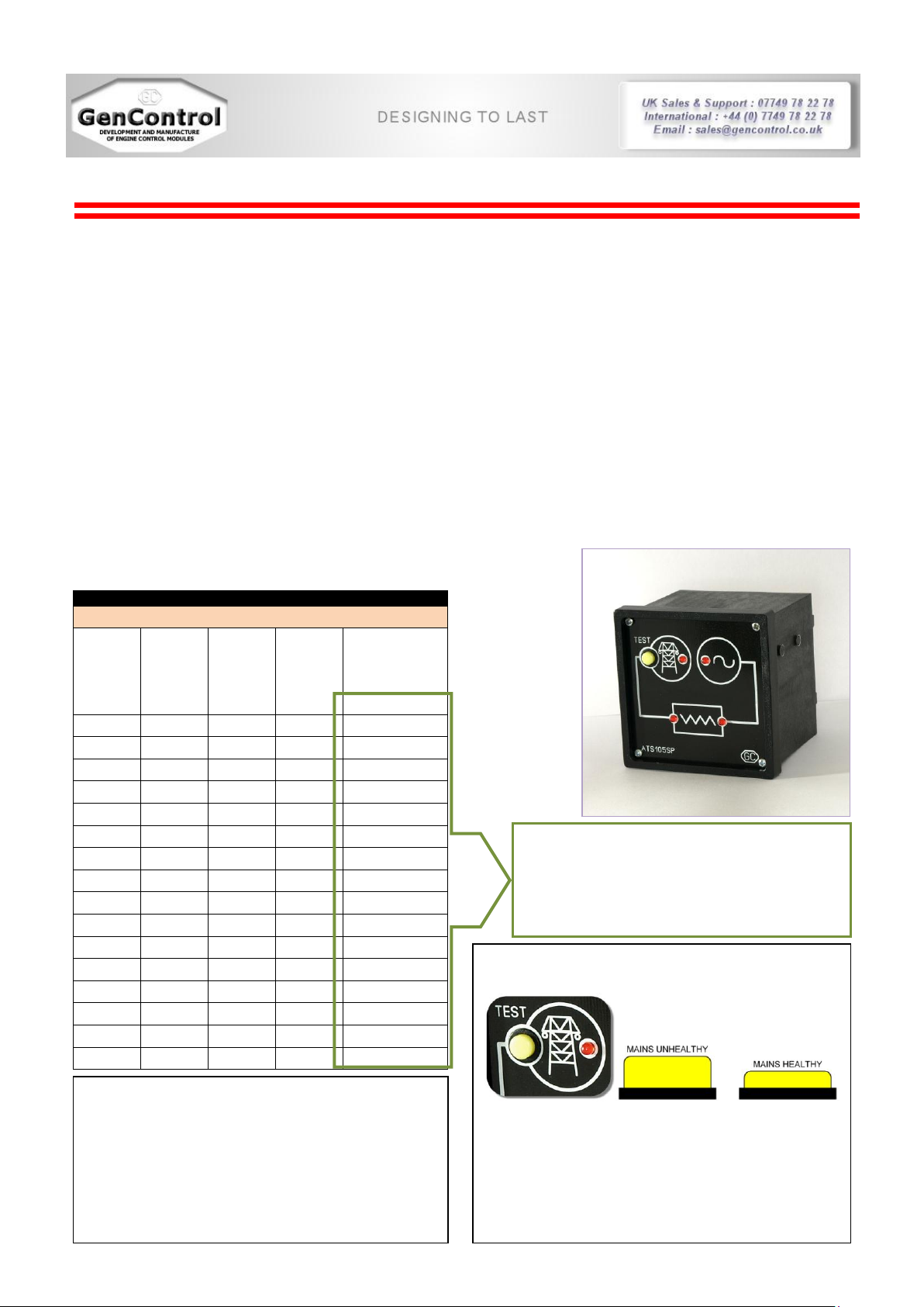
Automatic Transfer Switch ATS105SP
Description
The configurable Automatic Transfer Switch Model ATS105SP allows many of the industry’s demanding specifications to be
achieved. The ATS105SP is used to start a generator on a mains outage, sending a signal to the Auto Start Enabled Generator
and transfers the load when engine’s operating criteria has been met. The engine's warm-up time before accepting load and
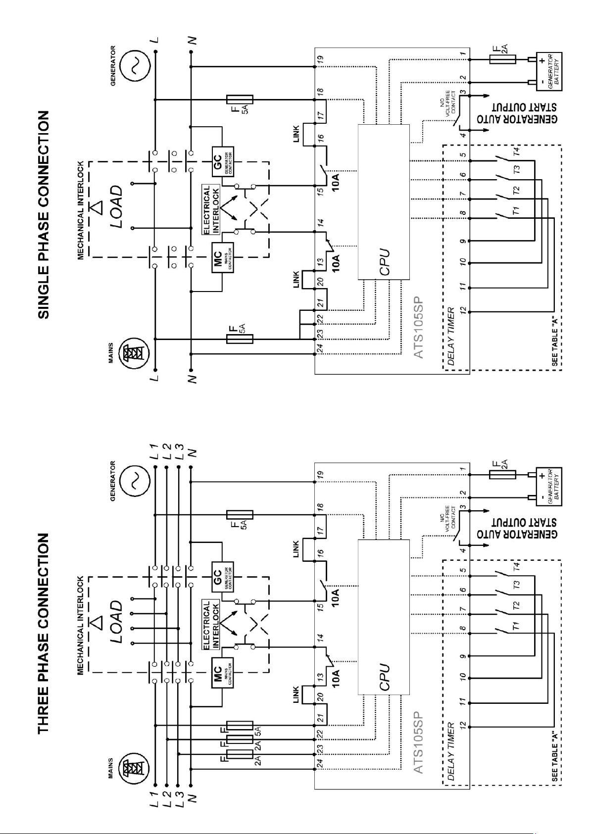
cool-down time after relieving load can be set directly on the module (by linking pins 5,6,7,8 and battery negative pins
9,10,11,12).The ATS105SP allows working on 3 phase and single phase mains/generator supply. Each phase is monitored
individually.
How it works
Under normal circumstances when mains power is available, National Grid power supply runs through the Automatic Transfer
Switch (ATS) contactors and connects to your distribution board. When mains power fails, the ATS will pause for a 25 sec.
period to ensure you haven’t had a power spike. ATS will then initiate a generator start signal (by closing terminals 3 and 4),
warm up the generator within preset time set by internal programmable timer* (see table A below) and then connect the
generator power supply to your home or business premises. Upon mains power being restored and stays healthy for more than
25 sec. the reverse happens and the controller automatically transfers load from the generator power back to mains shutting
down the generator after a cool-down period (cool-down period = warm-up period) and restoring it to standby mode. The
ATS105SP series modules have been designed for front panel mounting. The module is fitted into the cut-out (68X68mm) with
the fixing clips removed. These are then fitted from the rear.
Table A
*Internal programmable timer settings
T1
[pin 8]
T2
[pin 7]
T3
[pin 6]
T4
[pin 5]
Delay time
sec.
● ● ● 8
15
● 25
● ● ● 32
● 50
● ● ● ● 55
● ● 70
● 95
● ● 120
● ● 140
● ● ● 165
● 190
● ● 210
● ● 235
● ● ● 260
● ● 280
Specification
DC Supply: 12VDC/24VDC
Max. Operating Current: 80 mA at 12V
Max. Standby Current: 10 mA at 12 V
Alternator/Mains Input Range: 100 - 300 V AC
Frequencies supported: 50Hz and 60Hz
Mains/Generator Contactor Relay output:10 Amp at 250V AC
Generator Start Volt Free Relay output: 2 Amp. At 28V DC
Dimensions: 72 X 72 X 60mm
Operating Temperature Range: -30 to +70°C
2 X side clamps for secure panel fixing included.
Example: to set up 140 sec. (warm-up/cooldown) delay time link pin 6 & pin 7 to the
battery negative (pins 9,10,11,12 are all
negative).
Pins 8 & 5 are left unused.
BUTTON “TEST”
Button TEST is designed to simulate a mains outage condition.
Ones activated, the ATS105SP control module will pause for
25 sec. to make sure it is not returning back and then initiate
an isolation of the load from unhealthy mains, request a
generator start up and automatic connection of the load with
generator running after warm-up period set by internal timer is
timed out.
Page 2
 Loading...