

Genasun GVB-8-Pb-12V-WP, GVB-8-Li-14.2V-WP, GVB-8-Pb-48V-WP, GVB-8-Li-28.4V-WP, GVB-8-Li-41.7V-WP Series Manual
...
GENASUN
c/o BLUE SKY ENERGY
2598 FORTUNE WAY • SUITE K
VISTA, CA 92081 • USA
https://sunforgellc.com/genasun
GVB-8-WP (Boost) Manual
Waterproof Voltage Boosting Solar Charge Controllers with
Maximum Power Point Tracking
For models:
GVB-8-Pb-12V-WP: 12V Lead-Acid/AGM/Gel/Sealed/Flooded
GVB-8-Pb-24V-WP: 24V Lead-Acid/AGM/Gel/Sealed/Flooded
GVB-8-Pb-36V-WP: 36V Lead-Acid/AGM/Gel/Sealed/Flooded
GVB-8-Pb-48V-WP: 48V Lead-Acid/AGM/Gel/Sealed/Flooded
GVB-8-Li-14.2V-WP: 12V (4s) Lithium Iron Phosphate
GVB-8-Li-28.4V-WP: 24V (8s) Lithium Iron Phosphate
GVB-8-Li-41.7V-WP: 36V (10s) Lithium Cobalt/Magnesium/Nickel
GVB-8-Li-54.2V-WP: 48V (13s) Lithium Cobalt/Magnesium/Nickel
GVB-8-Li-56.8V-WP: 48V (16s) Lithium Iron Phosphate
GVB-8-Li-58.4V-WP: 52V (14s) Lithium Cobalt/Magnesium/Nickel
8A Input - 105W/210W/325W/350W
GENASUN GV-BOOST WP (ALL MODELS) MANUAL, REVISION 5.0 | 2019
IMPORTANT SAFETY INSTRUCTIONS | SAVE THESE INSTRUCTIONS

Safety Instructions:
This manual contains important instructions for the GV-Boost GVB-8-Pb-**V-WP and GVB-8-Li-**.*V-WP solar charge controllers that shall be followed
during installation and maintenance. Various models of the GVB-WP are available to charge different battery types as follows:
• GVB-8-Pb-12V-WP: 12V Lead-Acid/AGM/Gel/Sealed/Flooded
• GVB-8-Pb-24V-WP: 24V Lead-Acid/AGM/Gel/Sealed/Flooded
• GVB-8-Pb-36V-WP: 36V Lead-Acid/AGM/Gel/Sealed/Flooded
• GVB-8-Pb-48V-WP: 48V Lead-Acid/AGM/Gel/Sealed/Flooded
• GVB-8-Li-14.2V-WP: 12V (4s) Lithium Iron Phosphate
Consult your battery charging specifications to ensure that the GVB is compatible with your chosen batteries.
The GVB-8-WP includes an external 10A In-Line fuse rated for the maximum battery voltage.
WARNING: EXPLOSION HAZARD. DO NOT CONNECT OR DISCONNECT WHEN ENERGIZED. DO NOT REMOVE OR REPLACE FUSES UNLESS POWER
HAS BEEN DISCONNECTED OR THE AREA IS FREE OF IGNITIBLE CONCENTRATIONS. ATTENTION: RISQUE D'EXPLOSION. NE PAS CONNECTER NI
DÉCONNECTER PAS LORSQU'IL EST SOUS TENSION. NE PAS CONNECTER LE CIRCUIT ALORS QUE EST VIVANT OU A MOINS QUE LA ZONE EST
LIBRE DE CONCENTRATIONS IGNITAIRES. CAUTION for the GVB-8-Pb-**V-WP (Lead-Acid Versions Only): INTERNAL TEMPERATURE COMPENSATION.
RISK OF FIRE, USE WITHIN 0.3 m (1 ft) of BATTERIES. Lead-acid batteries can create explosive gases. Short circuits can draw thousands of amps
from a battery. Carefully read and follow all instructions supplied with the battery. DO NOT SHORT CIRCUIT the solar array when plugged into the
controller. DO NOT MEASURE SHORT CIRCUIT CURRENT of the array while connected to the controller. This may damage the controller, and such
damage will not be covered under warranty. Grounding is not necessary for operation and is at the user's discretion. If the GVB-WP is to be used
with a solar array electrically connected to earth ground, please note the following: WARNING: THIS UNIT IS NOT PROVIDED WITH A GFDI DEVICE.
Consult Article 690 of the National Electrical Code (or the standards in force at the installation location) to determine whether a GFDI is necessary for
your installation.
WARNING: THIS UNIT IS NOT PROVIDED WITH DISCONNECT DEVICES. Consult Article 690 of the National Electrical Code (or the standards in force
at the installation location) to determine whether disconnect devices are necessary for your installation.
• GVB-8-Li-24.8V-WP: 24V (8s) Lithium Iron Phosphate
• GVB-8-Li-41.7V-WP: 36V (10s) Lithium Cobalt/Mg/Ni
• GVB-8-Li-54.2V-WP: 48V (13s) Lithium Cobalt/Mg/Ni
• GVB-8-Li-56.8V-WP: 48V (16s) Lithium Iron Phosphate
• GVB-8-Li-58.4V-WP: 52V (14s) Lithium Cobalt/Magnesium/Nickel

LITHIUM WARNING: Use caution when working with lithium systems. Genasun Li controllers use the CC/CV charging profile indicated on the
controller. CHECK the specifications of the battery pack to ensure that the CV voltage is correct. Further check that the power supplied by the
solar array and Genasun controller is within the battery specified design limits.
LITHIUM BMS WARNING: Genasun recommends using a lithium battery with a Battery Management System capable of disconnecting the solar charge
controller in the event that any cell in the pack is outside of its rated temperature, current, or voltage range. Failure to do so may result in property damage,
injury or death. Genasun highly recommends the use of a BMS with cell balancing. Cell balancing is mandatory for lithium iron phosphate. Use only
copper conductors suitable for a minimum of 60 degrees C. If operation at high power or at high ambient temperatures is expected, wire with a higher
temperature rating may be necessary.
Product Certifications
EMC
Conforms to:
EN 61000-6-3:2007+A1:2011
EN 61000-6-2:2005
AS/NZS 61000-6-3:2012
EMC
Conforms to:
FCC (CFR Title 47) Part 15 Radio frequency
Devices, Subpart B - Unintentional
Radiators. Tested for compliance.
Restriction Hazardous Substances
Conforms to:
EN 50581:2012
Inspection & Maintenance
Inspect the controller at least once per year to ensure proper performance.
• Check for animal or insect damage.
• Inspect for corrosion / water damage.
• Inspect the security of all connections.
• Ensure the solar array does not exceed the maximum input voltage.
• Repair and clean as necessary.
Installation & System Connections:
• Connections should be made according to Article 690 of the National Electrical Code (NFPA 70)
or the standards in force at the installation location.
• Electrical connections may be made in any order; however the sequence below is recommended.
1
MOUNTING
Mount the controller near your battery securely using the holes provided on the enclosure’s anges or with a means
appropriate to the application.
• Mount near the battery (for lead-acid versions only, use within 0.3 m (1 ft) of batteries. See Caution, p.2).
• The GVB-8-WP can be mounted in any orientation on the oor or wall. We recommend a position in which all
labels are clearly visible.
• Do not mount in direct sunlight or near a source of heat.
• Allow adequate airow around the controller to achieve maximum output capability.
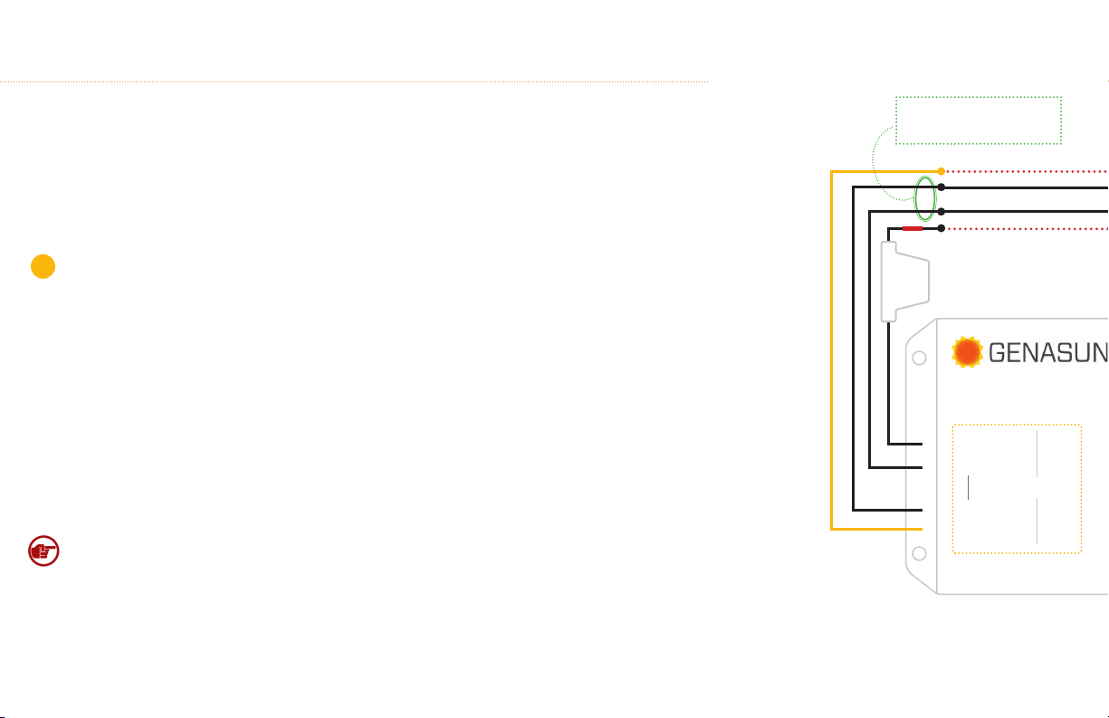
Note*: The positive or negative battery cable must be protected by a fast-acting fuse or circuit breaker of 10A or
less, rated for the maximum battery voltage and connected close to the battery terminal or power distribution
block. This fuse will protect the wiring in the event of a short circuit or controller damage.
Note: GVB is Negative Common,
"-Panel" and "-Battery" (both black
cables) are interchangeble.
10A IN-LINE FUSE
(INCLUDED)
VOLTAGE BOOSTING MPPT SOLAR CHARGE CONTROLLER
BAT T
+
BAT T
COMMON
+
PANEL
PANEL
MAX
8A

PANEL BATTERY
GVB-8-WP (Boost)
*FUSE
2
CONNECTING THE SOLAR PANEL
Connect the solar panel to the +PANEL and –PANEL terminals.
• In most applications, the panel should be connected only to the GVB-WP.
• The LED may blink red until a battery is connected.
• Do not use blocking diodes for single-panel installations. The GVB-WP prevents reverse-
current ow.
• If multiple panels are being used in parallel, blocking diodes are recommended in series
with each panel, unless the panel manufacturer recommends otherwise.
• Solar panel voltage rises in cold weather. Check that the solar panel open circuit voltage
(Voc) will remain below the maximum input voltage of the GVB-WP at the coldest possible
expected temperature.
Note: In the GVB-8-WP, the negative side of the battery is connected internally to the
negative side of the solar panel.
3
CONNECTING THE BATTERY
Connect the battery to the +BATT and –BATT terminals.
• A small spark while connecting the battery is ok.
• Any loads should be connected directly to the battery. The GVB-WP does not provide
protection against over-discharge.
The GVB-WP has a
MULTICOLOR LED.
Learn about this indicator
on the following page.
CAUTION, RISK OF FIRE OR EXPLOSION: Do not make the nal battery connection near
lead-acid batteries that have recently been charging.

Status Indication:
The GVB has a MULTICOLOR LED
LED ERROR INDICATION
Overheat: The controller’s internal temperature is too high.
SETS OF 2 RED BLINKS
LED RUN/CHARGE INDICATION
Standby: The battery is connected properly and ready to charge when solar
panel power is available.
2 SEC. BETWEEN BLINKS
Charging (low current, input current less than ~3.5A):
FAST & SHORT BLINKS
Charging (high current, input current more than ~3.5A):
LONGER, SLOWER BLINKS
Charging (current limit): charging at current limit.
The GVB is overloaded and limiting input current. Check that the solar
panel rating is within the GVB’s input specifications.
LONG, THEN SHORT BLINKS
Battery Charged: The battery is in the absorption
or float charging stage.
SOLID GREEN
Overload: The GVB has been overloaded.
This could be caused by changing the solar panel connections while the
controller is operating.
SETS OF 3 RED BLINKS
Battery voltage too high: Check that the correct GVB has been selected
for the nominal system battery voltage. If the nominal battery voltage is
correct, check the functioning of other chargers that may be connected
to the system. This error can also be caused by a disconnected battery or
blown fuse.
SETS OF 5 RED BLINKS
Internal Error: Contact your dealer for assistance.
2 LONG BLINKS, FOLLOWED BY ANY NUMBER
OF SHORT BLINKS
Battery voltage too low: The controller cannot begin charging due to
low battery voltage. Charge the battery by some other means before
use.
SETS OF 4 RED BLINKS
SOLID RED
OR OTHER LED INDICATIONS NOT LISTED

Troubleshooting
If the LED Indicator will not light, or displays an indication not listed in this manual:
• Verify correct battery polarity;
• Check that there is a solid electrical connection to the battery;
Note: The most common causes of blown fuses are:
• Connecting the GVB-8-WP to the battery backwards;
• Shorting the solar panel input while the GVB-8-WP is charging. In this case,
there may be internal damage to the controller.
• Check that battery voltage appears on the GVB-8 battery cables.
The GVB-8-WP will not operate without a battery. If the system appears to be overcharging or the GVB-8-WP will not begin charging, ensure that the solar panel is wired only to the GVB-8-WP.
If the GVB-8-WP does not appear to be charging, note that the GVB-8-WP waits up to one minute before trying to restart if is has shut down due to lack of power from the solar panel. If the
LED indicator will not light with a battery connected, or blinks the over-battery-voltage error, or the controller does not charge, the fuse may be blown. The GVB-8-WP fuse is located in a
black waterproof in-line fuse holder in the positive battery line. If the fuse is blown, replace it with a 10A fast-acting ATO or ATC fuse rated for the maximum battery voltage. Automotive-style
fuses are typically rated to 32V, and are suitable for the GVB-8-Pb-12V-WP, GVB-8-Pb-24V-WP, GVB-8-Li-14.2V-WP, and GVB-8-Li-28.4V-WP. For the GVB-8-Pb-36V-WP, GVB-8-Pb-48V-WP, GVB8-Li-41.7V-WP, GVB-8-Li-54.2V-WP, and GVB-8-Li-56.8V-WP, a fuse with a higher voltage rating is required. We recommend Littelfuse part number 142.6185.5102, rated 58V, or OPRIFUSE part
number APR58-UL-10A (UL# is JFHR2-E504903), rated 58V. For more in-depth system troubleshooting, please visit the support area of our website: https://sunforgellc.com/learning-center.
Specifications:
Rated Panel (Input) Current: 8A*
Minimum Panel Voltage for Charging: 5V
Minimum Battery Voltage for Operation: 9.5V
Maximum Input Panel: 60V
Recommended Max Panel Voc at STC: 50V
Input Voltage Range: 0-60V
Maximum Input Short Circuit Current**: 8A*
Maximum Input Current***: 15A
Operating Temperature: -40°C – 85°C
Maximum Full Power Ambient: 70°C
MPPT Tracking Speed: 15Hz
Environmental Protection: IP68, Waterproof
Connection: Flying Leads, 16 AWG tinned wire, pre-stripped
Certications: CE, FCC, RoHS
*Panel ratings have increased since we designed the GVB. Although we don't believe in changing specications without a corresponding engineering change, based on both our customers' experiences over the years as well as the
headroom we designed into the GVB, we feel comfortable recommending the GVB for panels with Imp up to 9A. **Panel Isc. Maximum input power and maximum input voltage requirements must also be respected. ***Maximum
current that the controller could draw from an unlimited source. This specication is not intended for determining PV input.
GVB-8-WP, All Models

Specifications (cont.):
Weight: 10.3 oz. , 290 g
Dimensions: 5.5 x 3.2 x 2.2”, 14 x 8.1 x 5.5 cm
Warranty: 5 years
GVB-8-Pb-12V-WP
Charge Prole: Multi-Stage with Temperature Compensation
Nominal Battery Voltage: 12V 24V 36V 48V
Maximum Recommended Panel Vmp: 13V 26V 41V 43V
Maximum Recommended Panel Power
(8A Panel w/~155mm cells):
Bulk Voltage: 14.4V 28.8V 43.2V 57.6V
Absorption Voltage: 14.2V 28.4V 42.6V 56.8V
Absorption Time: 2 Hours
Float Voltage (Pb models) or
CV Voltage (Li models):
Battery Temperature Compensation:
(referred to 25°C)
Electrical Eciency: 95% - 97% typical 96% - 98% typical 96% - 98% typical 96% - 99% typical
Night Consumption: 7mA 6mA 6mA 5mA
105W 210W 325W 350W
13.8V 27.6V 41.4V 55.2V
-28mV/°C -56mV/°C -84mV/°C -112mV/°C
GVB-8-Pb-24V-WP GVB-8-Pb-36V-WP
GVB-8-WP, All Models
GVB-8-Pb-48V-WP
GVB-8-Li-14.2V-WP GVB-8-Li-28.4V-WP
Battery type: 4S LiFePO4 8S LiFePO4 10S Li-ion 13S Li-ion 16S LiFePO4 14S Li-ion
Charge Prole: CC/CV CC/CV
CV Voltage: 14.2V 28.4V 41.7V 54.2V 56.8V 58.4V
Battery Temperature Compensation: Disabled
Maximum Recommended Panel Vmp: 13V 26V 39V 43V 43V 43V
Maximum Recommended Panel Power: 105W 210W 325W 350W 350W 350W
Electrical Eciency: 95% - 97% typical 96% - 98% typical 96% - 98% typical 96% - 99% typical 96% - 99% typical 96% - 99% typical
Night Consumption: 7mA 6mA 6mA 5mA 5mA 5mA
Copyright © 2019 Sunforge LLC. All rights reserved. Changes are periodically made to the information herein which will be incorporated in revised editions of this publication. Sunforge may make
changes or improvements to the product(s) described in this publication at any time and without notice.
GVB-8-Li-41.7V-WP GVB-8-Li-54.2V-WP
GVB-8-Li-56.8V-WP
GVB-8-Li-58.4V-WP
 Loading...