

Page 1
565/575
FEEDER MANA GEMENT RELAY
Instruction Manual
Software Rev: E2.73
Manual P/N: 1601-0017-E6
Copyright 1996 GE Multilin
®
CANADA USA
215 Anderson Avenue, Markham, Ontario, L6E 1B3 9746 Whithorn Dr., Houston, Texas, 77095
Tel: (905) 294-6222 Fax: (905) 294-8512 Tel: (713) 855-1000 Fax: (713) 859-1091
Page 2

SECTION 1: INTRODUCTION
Protection Requirements of Feeders ......................... 1-1
565 Relay Features.................................................... 1-1
Setpoint Programming ............................................... 1-1
Inputs ......................................................................... 1-1
Outputs ...................................................................... 1-1
Memory Features ....................................................... 1-1
Typical Applications.................................................... 1-1
Ordering Information .................................................. 1-1
SECTION 2: INSTALLATION
Unpacking the Unit..................................................... 2-1
Mounting the Relay .................................................... 2-1
Making Wiring Connections ....................................... 2-1
Power Supply Connections........................................ 2-1
Surge Ground Connection ......................................... 2-1
Current Transformers.................................................2-1
Voltage Transformers................................................. 2-1
Breaker Status and Control Connections .................. 2-4
Aux 1 Contacts........................................................... 2-4
Aux 2 Contacts........................................................... 2-4
Aux 3 Contacts........................................................... 2-4
Aux 4 Contacts........................................................... 2-4
Programming Port ...................................................... 2-4
Communication Port .................................................. 2-4
MTM Port ................................................................... 2-4
Printer Port ................................................................. 2-4
Analog Output Terminals............................................ 2-5
Analog In Terminals ................................................... 2-5
External Switches 1 to 8 ............................................ 2-5
Access Terminals ....................................................... 2-5
Remote Trip/Close Terminals ..................................... 2-5
Removal of Cradle ..................................................... 2-5
Inserting Cradle.......................................................... 2-5
Metering Transducer Module ..................................... 2-5
Hi-Pot Testing ............................................................. 2-6
SECTION 3: PROTECTION APPLICATION INFORMATION
Overcurrent Protection............................................... 3-1
Use of Standard Curves............................................. 3-1
Use of Custom Curve................................................. 3-1
TABLE OF CONTENTS
SECTION 7: FEATURE INFORMATION
Event Recording Information ..................................... 7-1
AEG MODICON MODBUS PROTOCOL ................... 7-6
Memory Map Information ......................................... 7-11
Metering Specification - 565 with MTM.................... 7-23
SECTION 8: RELAY TESTING
Primary Injection Testing ............................................ 8-1
Secondary Injection Testing ....................................... 8-1
Phase Current Input Function Check......................... 8-1
Phase Instantaneous Pickup and Trip Check............ 8-1
Phase Overcurrent Curve Verification ........................ 8-1
Ground Current Input Function Check ....................... 8-3
Ground Instantaneous Pickup and Trip Check .......... 8-3
Ground Curve Verification.......................................... 8-3
Voltage Input Function Check .................................... 8-4
Undervoltage Trip and Alarm Check .......................... 8-4
Overvoltage Trip and Alarm Check ............................ 8-4
Output Relay Functional Check ................................. 8-4
Analog Input Function Check..................................... 8-4
Analog Output Function Check .................................. 8-4
Power Loss Check ..................................................... 8-4
SECTION 9: TECHNICAL SPECIFICATIONS
Technical Specifications............................................. 9-1
APPENDIX A
Customer service .......................................................A-1
APPENDIX B
Troubleshooting guide. .............................................. B-1
APPENDIX C
Block Diagrams ..........................................................C-1
APPENDIX D
Curve: Normal Inverse ..............................................D-2
LIST OF FIGURES
SECTION 4: DISPLAY AND KEYBOARD
Display Modes ........................................................... 4-1
Actual Values Mode ................................................... 4-1
Setpoints Mode .......................................................... 4-1
Help Mode.................................................................. 4-2
SECTION 5: ACTUAL VALUES MODE
Default Message Selection ........................................ 5-1
Actual Values Message Abbreviations....................... 5-1
Summary of Actual Value Page Contents .................. 5-2
Actual Values. ............................................................ 5-3
SECTION 6: SETPOINTS MODE
Relay Selection .......................................................... 6-1
Setpoint Message Abbreviations ............................... 6-1
Summary of Setpoint Page Contents. ....................... 6-3
Factory Default Setpoints. ......................................... 6-4
Setpoints. ................................................................... 6-8
Installation of Security Feature: ............................... 6-10
Use of Access Code:................................................ 6-10
i
Page 3

Protection Requirements of Feeders
Protection of three phase feeders is necessary to avoid
equipment damage and personnel injury during fault conditions. The fact that continuous reliable power must be provided to the distribution network means that the feeder protection relay must protect the network and personnel and yet
not cause unnecessary loss of power or nuisance tripping.
The ideal Feeder Management Relay should at least monitor
phase current, ground current and voltage in the network,
provide indications if any of these reach predetermined levels
and provide appropriate trip signals if fault conditions develop.
The advent of current microprocessor technology has enabled the development of feeder management relays which do
this task much better than conventional relays and provide
other desirable features. Measured values of phase current,
ground current and voltage can be displayed.
Entering setpoints to the microprocessor based Relay is
made easier by use of a keypad and a LCD display to guide
the user. A “help” menu is available at all times.
Relay Features
The Multilin Feeder Management Relay is designed to provide complete and accurate feeder protection under all operating conditions. The relay provides complete Time/Overcurrent phase and ground protection by monitoring feeder phase
currents and ground currents. These are sensed by current
transformers (CT’s).
INTRODUCTION
All setpoints are tamper-proof. This is achieved through the
use of a combination of a Access wire jumper at the back of
the relay and personalized codes. These codes allow even
the wire jumper to be overridden, for added security.
Inputs
The Relay has inputs which can be used for indication of
breaker status or external differential trips such as the industry standard ’87T’.
One set of inputs is designated “Analog Select”, and can be
connected to four dry contacts of a programmable logic
controller (PLC). Selected outputs can be requested one by
one, through these inputs by the PLC. Information can be
requested on values such as individual phase currents and
the Relay will send the requested value through the analog
output terminals in either 0-1mA or 4-20mA format as required.
Outputs
Six electromechanical output relays are included in the 565/
575 Relay. These are named Tr ip, Close, Aux. 1, 2, 3, and 4.
These relays can be allocated various functions, by using the
flexibility of the software programming.
Actual value and Setpoint information is sent out through the
RS485 port on the rear of the relay.
port is also available for printing out events from the event
recorder if an Option Card is installed. **
panel RS232 programming port is provided.
** An RS232 printer driver
In addition, a front
Overcurrent phase and ground current trip setpoints are
programmed by a comprehensive selection of industry standard curve shapes including moderately inverse, normal inverse, very inverse, and extremely inverse. In addition to the
pre-selected curves there is also a programmable custom
curve. If none of the pre-selected curves are suitable for the
application, the user can enter his own data to form the
custom curve.
Setpoint Programming
The relay can hav e its setpoints prog rammed locally, from the
front panel. In this case the alphanumeric display guides the
user through the setup, step by step, giving clear English
language instructions. There is also a HELP k e y which can be
pressed at any time to get information and assistance about
the current programming step.
The status of the system is clearly displayed at all times by
LED indicators and more detailed information can be shown
on the display screen if requested through the keypad.
When an output relay is activated to cause a trip/alarm the
Relay will display the cause of the trip/alarm.
Memory Features
In order to simplify fault analysis and thus improve system
reliability, several memory features have been built into the
Relay. The event recording feature provides a record of the
events leading to a trip so that the faulty feeder system
component can be located easily.
The memory feature provides a record of the cause of all
trips. This is extremely useful in determining preventiv e maintenance requirements and identifying problem areas.
Typical Applications
The Relay is ideally suited for primar y protection of medium
and high voltage distribution systems.
1-1
Page 4
INTRODUCTION
Ordering Information
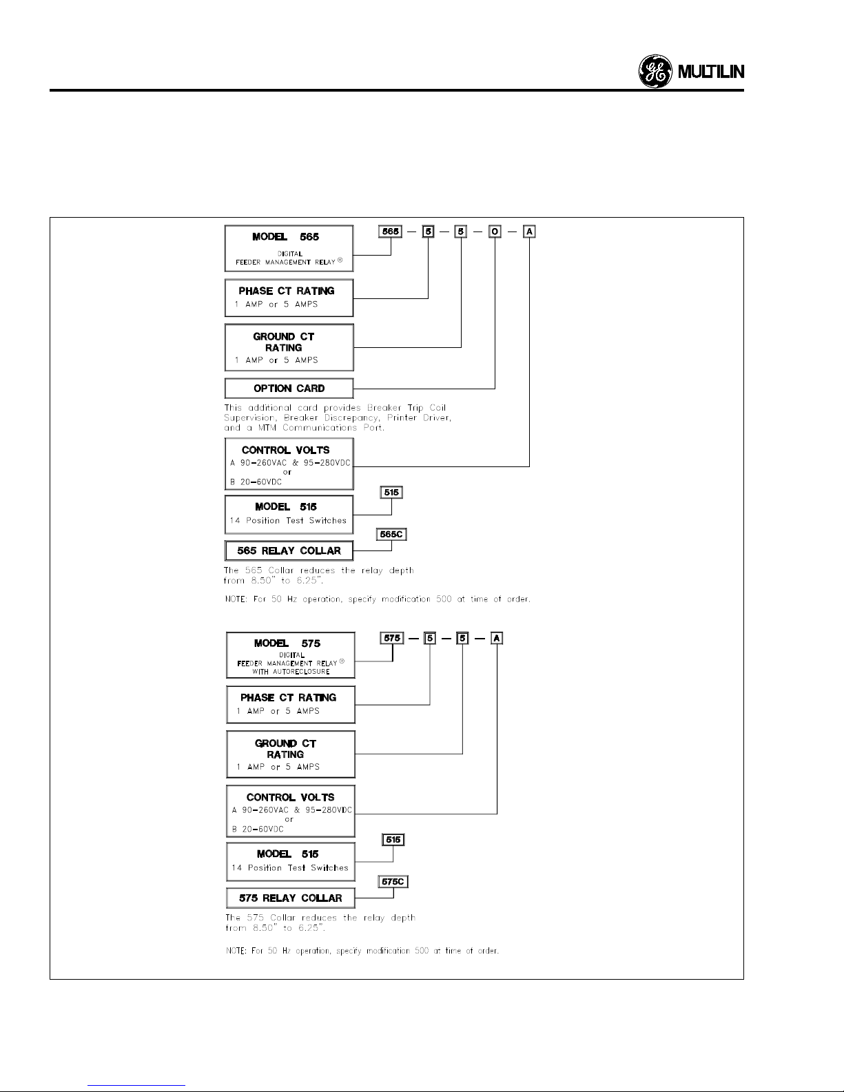
To order the Feeder Protection Relays you must specify it as
shown in Figure 1.1.
Many features of the Relay are field programmable. Those
listed in Figure 1.1 are not, and must be specified when
ordering.
Additional features may be available for special orders. Contact GE MULTILIN for further details.
1-2
Figure 1.1 Order Codes
Page 5

Unpacking the Unit
The shipping container should contain your Relay and this
manual. Inspect the unit and inform GE MULTILIN of any
damage. If re-shipment is required the or iginal container and
packing should be used.
INSTALLA TION
designed to operate within one of the following voltage
ranges:
1. 90-260 VAC and 95-280 VDC
2. 20-60 VDC
No internal or external adjustments are required to use any
of the above supply voltages.
Mounting the Relay
The Relay is designed to be panel mounted. It should be
located so that the keypad is accessible with the door
opening from the right. The unit should be mounted so that
the display is easily visible. It is recommended that the relay
be mounted as far away as possible from heavy current
sources and strong magnetic fields.
The 4 mounting studs of the Relay are equipped with (1) #10
internal star lockwasher, (1) 10-32 threaded hex spacer
0.25" long, (1) #10 split lockwasher, and (1) 10-32 hex nut.
Remove only the split lockwasher and the 10-32 hex nut
before installing the Relay in the panel. Then use this split
lockwasher and hex nut to secure the Relay in the panel.
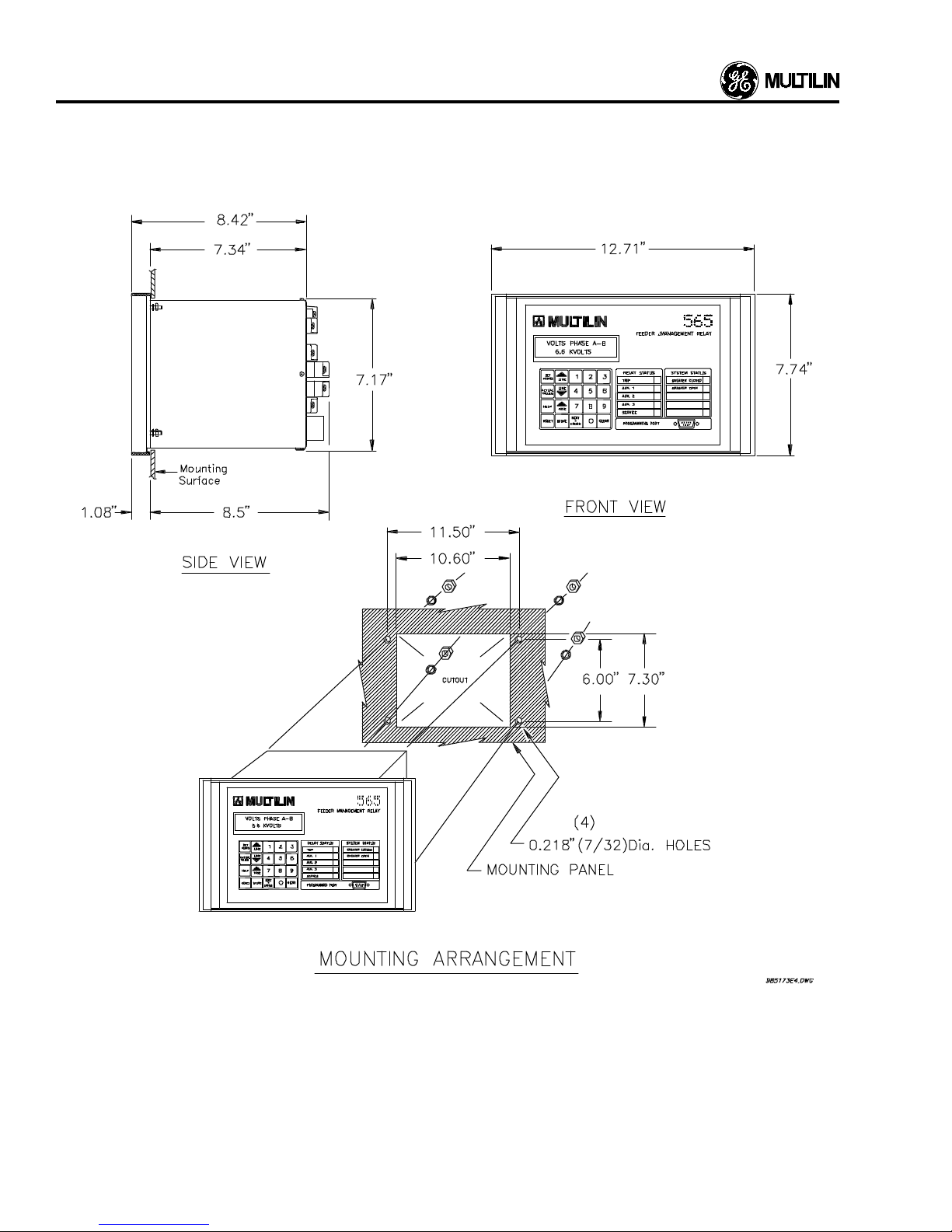
The dimensions of the unit and the necessary cutout dimensions are shown in Figure 2.1.
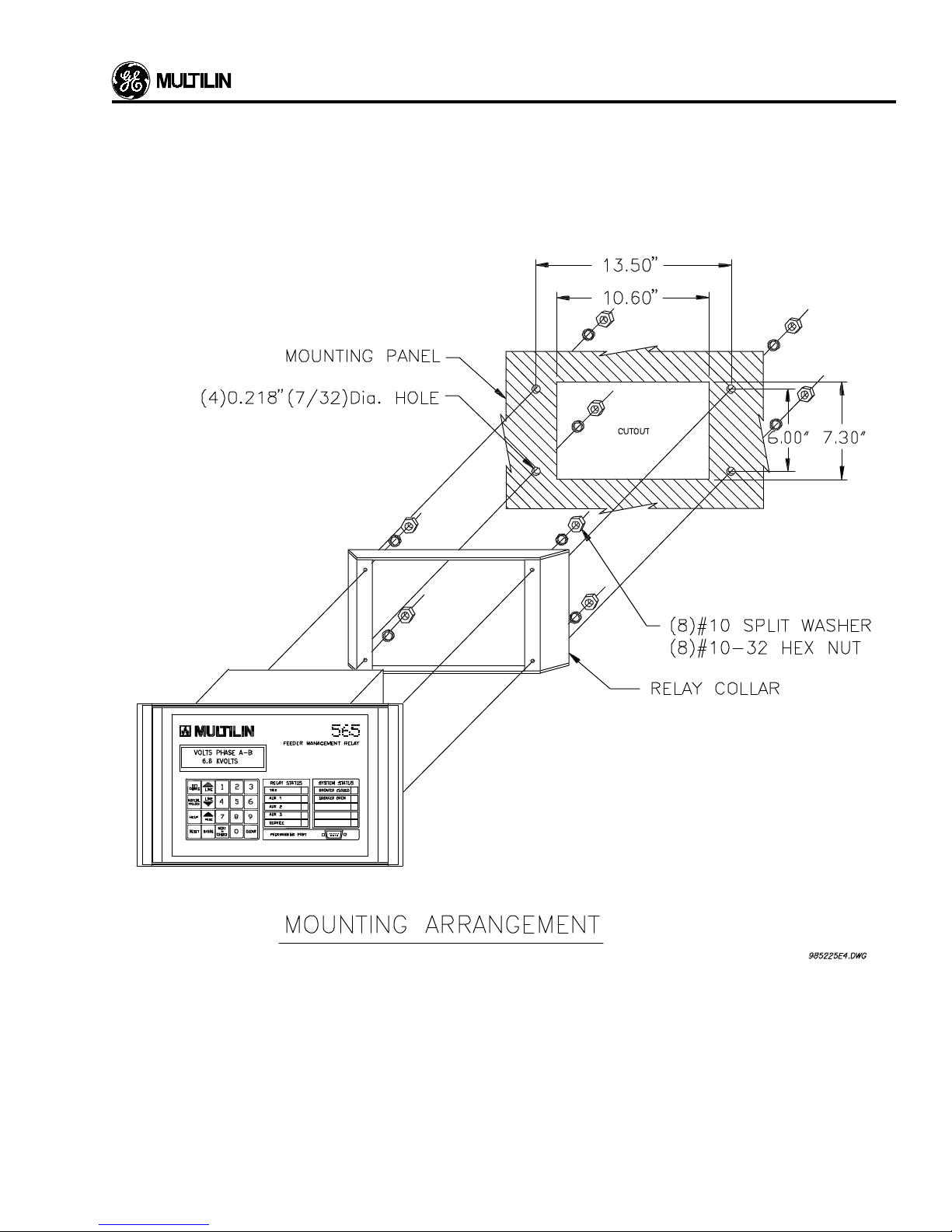
To reduce the required space behind the mounting panel an
optional depth reducer is available. This reduces the depth to
6.25". It increases the width of the front panel to 15.33". For
mounting dimensions see Fig. 2.2.
Making Wiring Connections
All wiring connections to the Relay are made at the back of
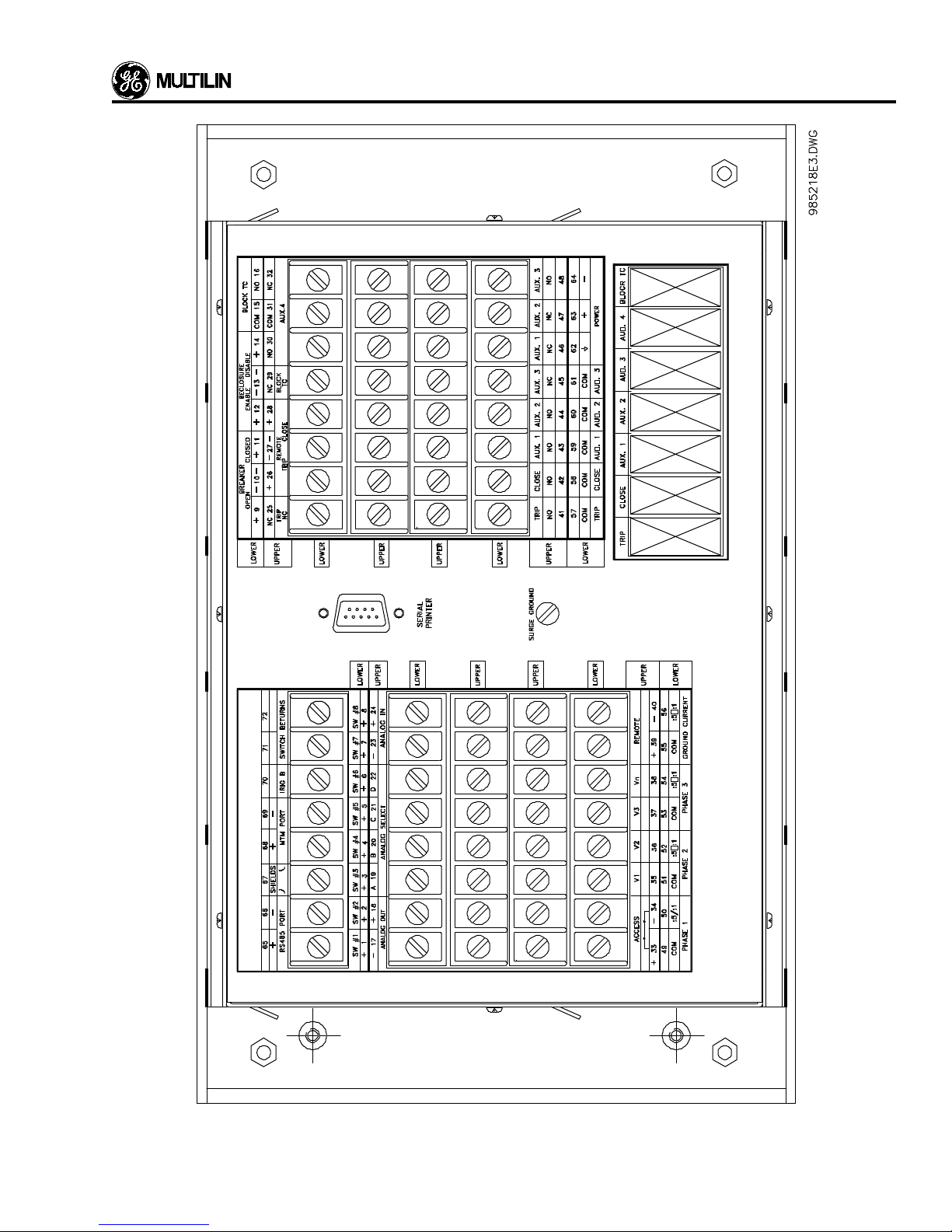
the unit as shown in Figure 2.10. All terminals are also
identified in Table 2-1 with their functions.
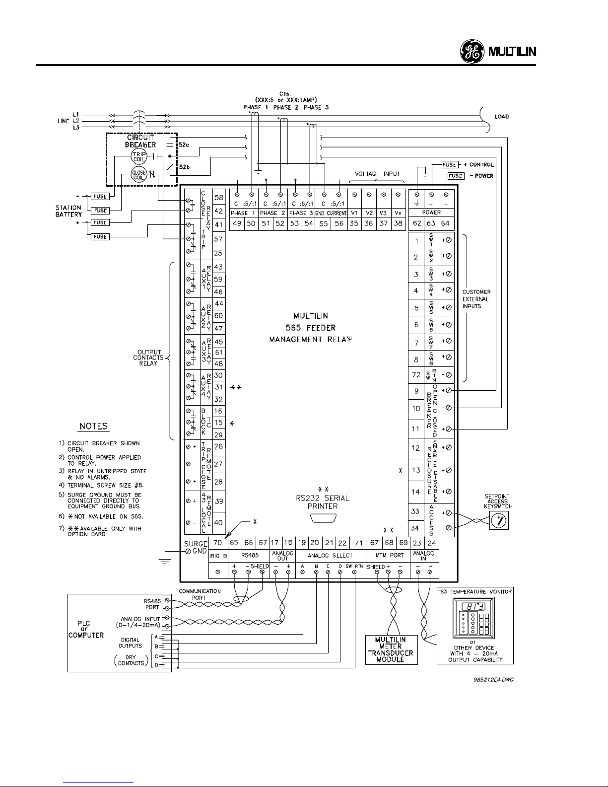
Figure 2.5 shows the connections for a typical installation.
The actual connections made to the Relay will va ry according
to the application. All contacts in the figure are shown in the
state they will hav e with control power applied to the unit. T he
contacts are shown in the “non-active” state.
The relay can be removed from the outside case for the
purpose of checking and/or calibration. The wiring is to the
outside and remains intact.
Power supply connections are made at terminals 63 and 64.
The relay is grounded by connecting terminal 62 directly to
the dedicated ground entering the switchgear enclosure.
Surge Ground Connection
For safety and optimum noise immunity due to transients, a
low impedance connection must be made between the surge
ground terminal and the switchgear ground. This must be a
separate, dedicated wire tied directly to the switchgear copper bus strip (flat, braided wire is ideal).
CAUTION
FAILURE TO MAKE PROPER GROUND CONNECTIONS
MAY CAUSE DAMAGE TO THE RELAY.
Current T ransformer s
The three current transformers supply the Relay with currents proportional to the current in each of the phases of the
feeder being protected. They are connected to terminals 49
to 54 as shown in Figure 2.5. Observe correct polarity when
connecting the current transfor mers to the unit.
The CT terminal with the dot marked on it must be connected
to the terminal marked “:5/:1”. Each CT should have the
same physical orientation, with polarity connected as shown
in Figure 2.5. The sides of the CT which are not marked with
a polarity dot are connected together and grounded.
Residual ground sensing is provided b y connecting the common terminals of the three CTs together through the ground
sensing input terminal 56 as shown in the wiring diagram,
Figure 2.5. These connections allow the relay to check the
vector sum of all three phase currents. If this is not zero, a
ground fault condition is sensed by the unit.
WARNING
Extreme caution must be exercised when the chassis is
withdrawn from an in service unit as this exposes live
terminals.
Power Supply Connections
Depending upon the ordered power supply, the Relay is
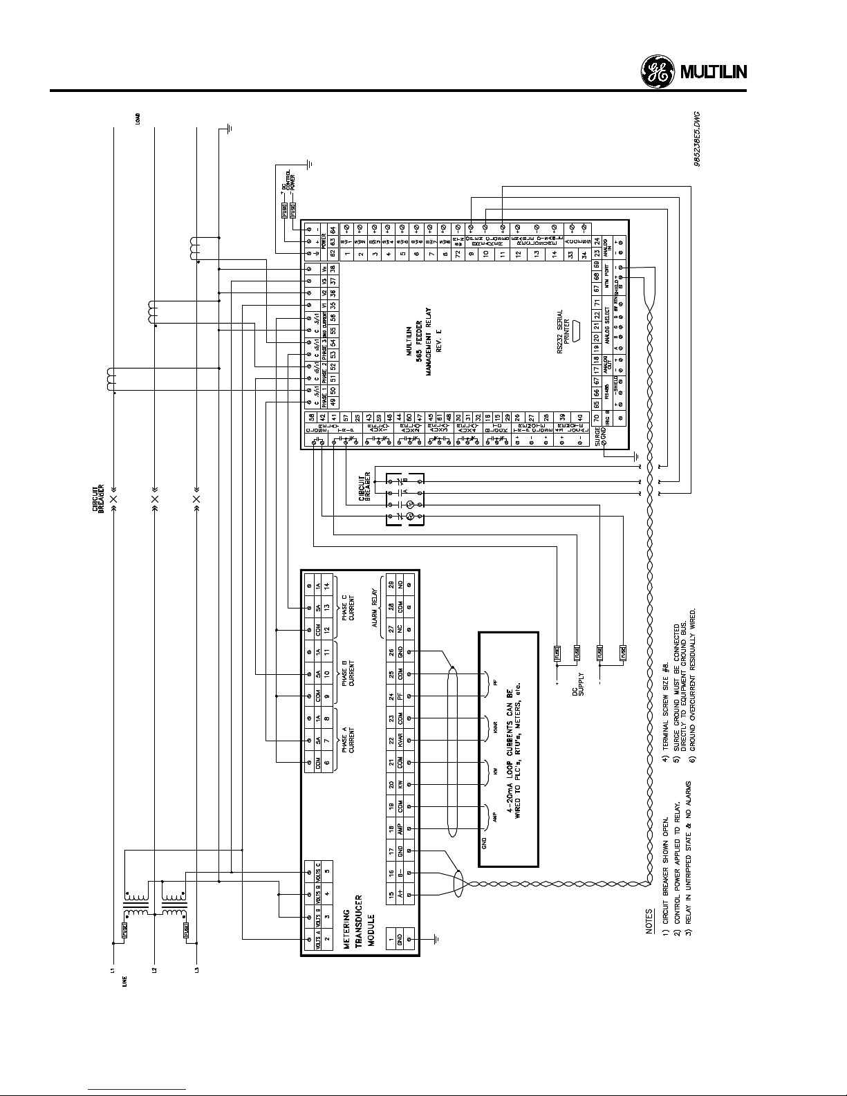
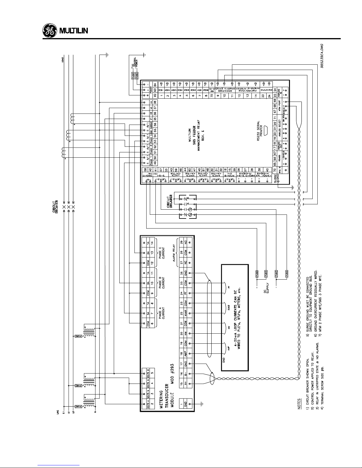
For typical CT wiring of the Relay with the optional Metering
Transducer Module (MTM) see Figure 2.7A and Figure 2.7B.
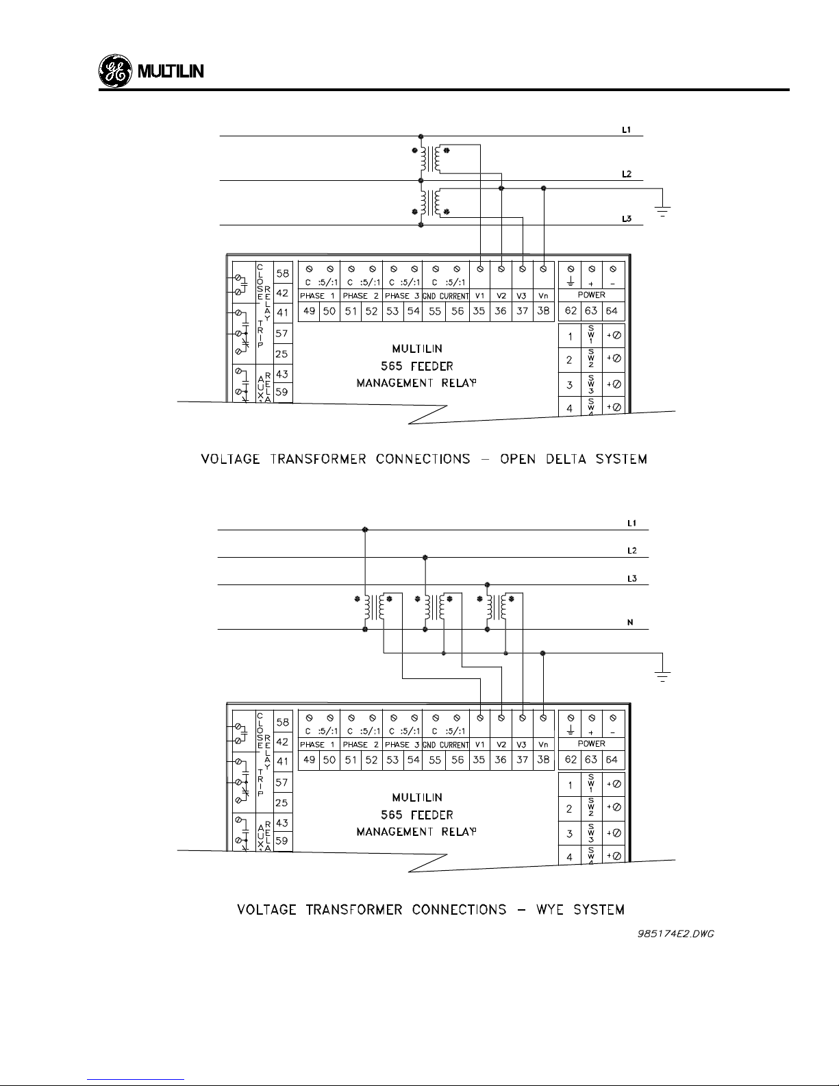
Voltage Transf ormers
Separate voltage transformers are needed for voltage sensing and terminals 35 to 38 are used for this. The transformers
can be connected in either Wye or Open Delta configuration
as shown in Figure 2.6.
2-1
Page 6
INSTALLATION
2-2
Figure 2.1 Mounting Details
Page 7
INSTALLA TION
Figure 2.2 Mounting Arrangement with Relay Collar
2-3
Page 8
INSTALLATION
Breaker Status and Control Connections
The Feeder breaker status indications are given to the Relay
from the auxiliary 52a/52b contacts on the breaker. The
connections are made to terminals 9 and 10 for the Breaker
open indication (52b) and at terminals 11 and 10, for break er
closed (52a) as shown in Figure 2.5. The breaker status input
connections must be made.
Aux 1 Contacts
The contacts of the Aux 1 are 43 N.O., 59 common, 46 N.C.
This relay function is programmable.
Aux 2 Contacts
The contacts of Aux 2 are 44 N.O., 60 common, 47 N.C. This
relay function is programmable.
Aux 3 Contacts
The contacts of Aux 3 are 45 N.C., 61 common, 48 N.O. This
relay is hot coil failsafe and monitors control power loss, and
trip coil supervision. It is not programmable.
Aux 4 Contacts
The contacts of Aux 4 are 30 N.O., 31 common, 32 N.C. This
relay activates on a Breaker Discrepancy function if enabled.
** Available only with Option Card **.
Block Tap Changer (
The contacts of the Block Tap Changer are 16 N.O., 15
common, and 26 N.C. This relay operates to block operation
of an external transformer tap changer. It also acts as “Auto
Reclosure in Progress” indicator.
575 only
)
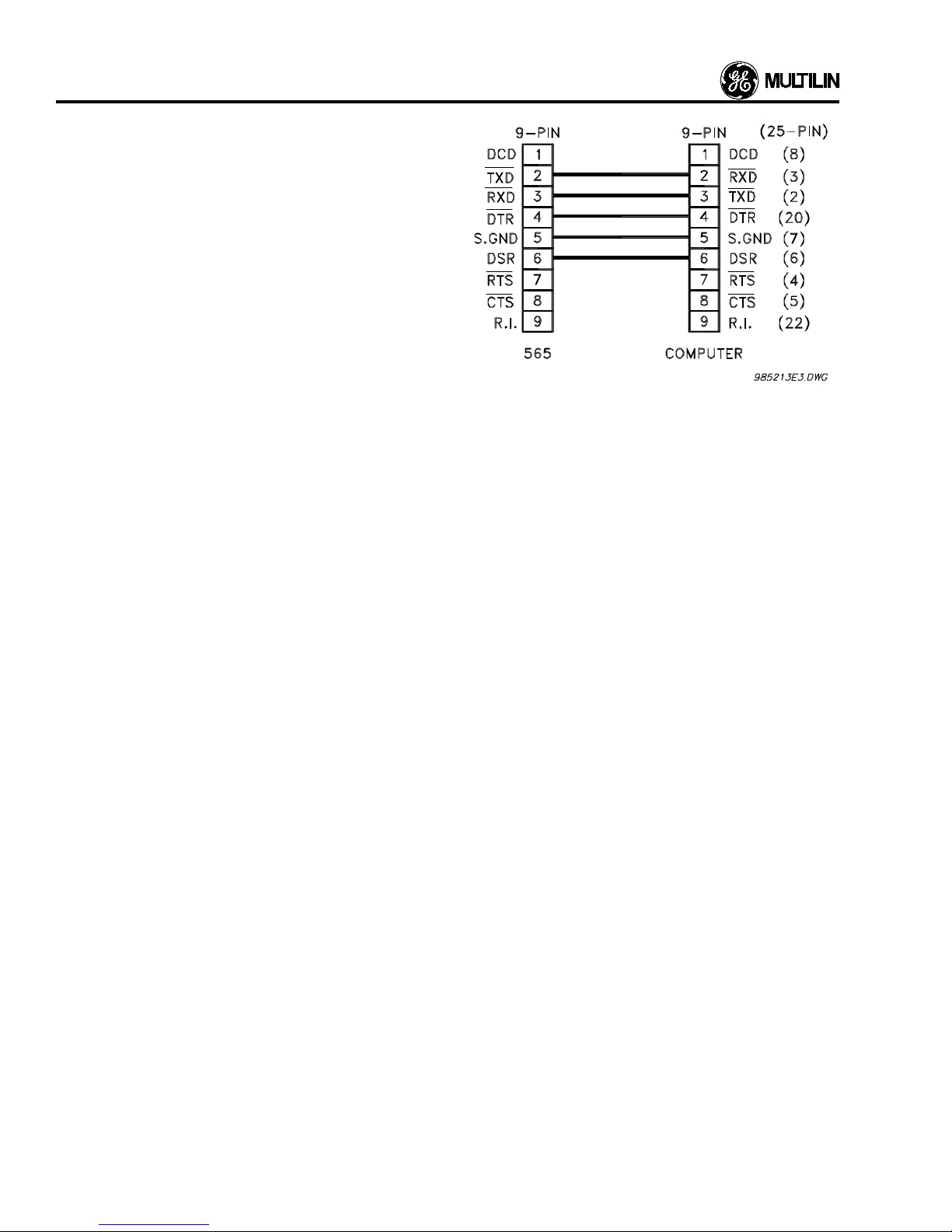
Programming Port
Figure 2.3 Computer Interface Cable for RelayCom
Package
Communication Port
Up to 32 relays can be daisy-chained together and connected to a computer or a programmab le controller using the
RS485 type communication port in the rear. A shielded
twisted pair should be used and proper polarity has to be
observed. ie. positive to terminal 65, negative to terminal 66,
while the shield is connected to terminal 67.
After each 565/575 Relay is assigned a unique address, the
master device (computer) can read measured values or
store setpoints. The address is assigned via the keypad on
the front panel. See also Programming Port information
above.
MTM Port
The MTM port, terminals 67, 68, and 69, is required when
connecting the separate MTM Metering Transducer Module
to the 565/575 Relay. The MTM receives current and voltage
inputs and calculates KW, KVAR, PF and transmits the
information to the 565/575 Relay. The connections are made
by means of a shielded twisted pair of length no greater than
50 ft. MTM port polarity must be observed. ie. positive to 68,
negative to 69, and the shield to 67.
Option Card **.
** Available only with
A programming port (RS232 type) is supplied on the front
panel of the relay. This port can be connected to a computer
which then can be used to store setpoints in and read
measured values from the relay.
This port has prior ity over the communication port on the
rear. If the relay senses the DTR line being pulled high, all
communications at the rear are suspended.
The connection to a computer is made via a standard
modem type cable and is shown in figure 2.3.
2-4
Printer Port
The printer port can be used to connect a printer to record
event recording output. This is a 1200 baud serial output with
even parity and requires the printer to accept serial data. The
word length is elev en bits with the data fr ame constructed as
follows: there is a start bit
an even par ity bit, and a stop bit
MSB),
tion is made at the rear of the relay via a 9 pin D-type null
modem connector. The pinout is as follows:
(Low)
, eight data bits
(High).
(LSB to
The connec-
Page 9

2 = transmit data to printer
3 = receive data from printer
4 = Clear To Send from printer
5 = signal ground.
See your printer manual f or connections at the printer.
able only with the Option Card installed **
Analog Output Terminals
** Avail-
INSTALLA TION
Access T erminals
Terminals 33 and 34 can be connected to a keyswitch. The
565/575 Relay setpoints cannot be changed unless this
keyswitch is closed (ie. 33 and 34 are connected together).
This prevents unauthorized personnel from tampering with
the setpoints once they are set up. This function can be
defeated using the Security feature. Refer to Setpoint Programming.
Terminals 17 and 18 provide a single output that can be
programmed as 4-20 mA or 0-1 mA to correspond from zero
to full scale.
Using the analog select terminals 19-22, and 71, outputs can
be selected by placing a binary code on inputs A-D . This code
can be PLC controlled for changing the output selection. This
allows monitoring and plotting measured values such as
phase current, using a single analog input channel of a
programmable controller.
If a single output parameter is desired, this is achieved through
setpoint programming without external connections to inputs A-D.
Analog In Terminals
The 565/575 Relay is designed to accept an input from
standard 4 to 20 mA source such as a Multilin TS3 Temperature Monitor. This input can be used to provide status or trip
signals related to the level of the input, a transformer winding
temperature, for example. The setup of the trip, alarm or
status indications are done during the software programming
in the Setpoints mode.
The input terminals are positive 24, and negative 23.
Remote T rip/Close T erminals
When terminals 39 and 40 are “open”, the 565/575 relay is
operating in Local Mode. If this is the case, terminals 26, 27,
and 28 will have no eff ect upon either the Close (terminals 42
and 58) or Trip (terminals 25, 57, and 41) output relays.
When terminals 39 and 40 are “closed”, the 565/575 relay is
operating in Remote Mode. Now if ter minals 27 and 28 are
shorted, the Close output relay becomes energized and if
terminals 26 and 27 are shorted, the Trip output relay becomes energized. Note that each relay will be picked up for
as long as the appropriate switch input remains closed.
This operation is completely independent of software and is
strictly under hardware control.
Removal of Cradle
To remove the cradle from the case, open the door and
unscrew the locking screw fasteners. The cradle can now be
removed simply by pulling on the front handle. Caution
should be taken when the cradle is removed as this exposes
live terminals in the case.
External Switches 1 to 8
The 565/575 Relay can accept switch inputs from eight
external switches, through terminals 1 to 8. The function of
switches 1 to 8 is user definable. They can be programmed to
perform functions such as preventing certain feeder breaker
trips or introducing a time delayed alarm. These features are
assigned to the switches in the Configuration page of Setpoints mode.
CAUTION
External Switch inputs should be connected to dry circuits
only to prevent damage to the relay.
No external voltage should be applied to these terminals as
the contacts are energized internally from the 565/575 and
opto-coupled to the sensing circuitry. Switches should be
isolated from each other for correct operation. The maximu m
input impedance to these external switches is 2 kΩ.
Inserting Cradle
To insert the cradle, align the aluminum guides on the sides
of the cradle with those inside the case and slide the cradle
into place. Ease in with constant pressure. Once inserted,
the yellow guideline should be visible. The locking screw
fasteners can now be screwed in and tightened. NOTE: The
locking screw fasteners should be locked at all times while
the cradle is inserted to ensure that proper connection to the
rear terminals is maintained.
CAUTION
Do not press on the LCD display when removing or installing the unit.
2-5
Page 10

INSTALLATION
Metering Transducer Module
The Metering Transducer Module is an optional unit which
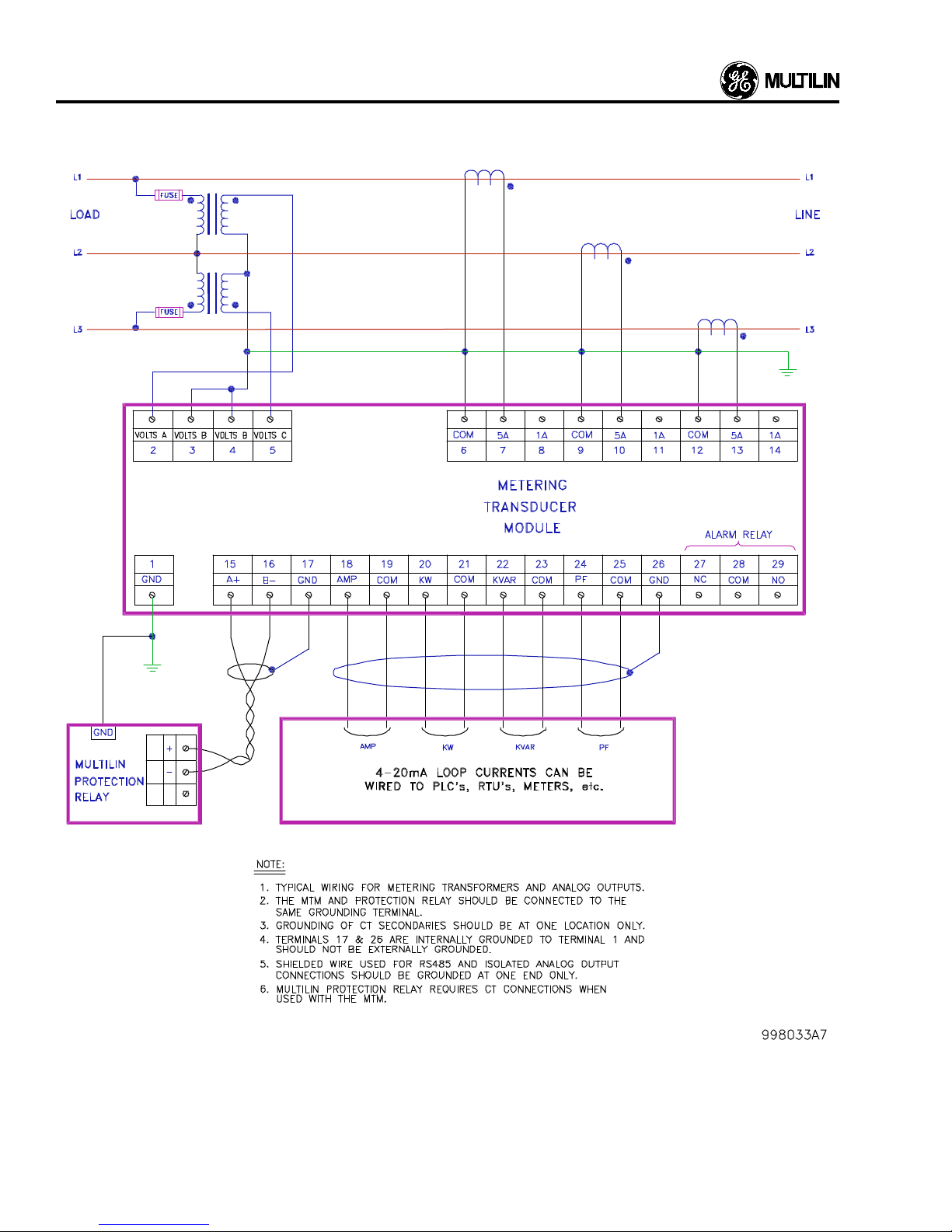
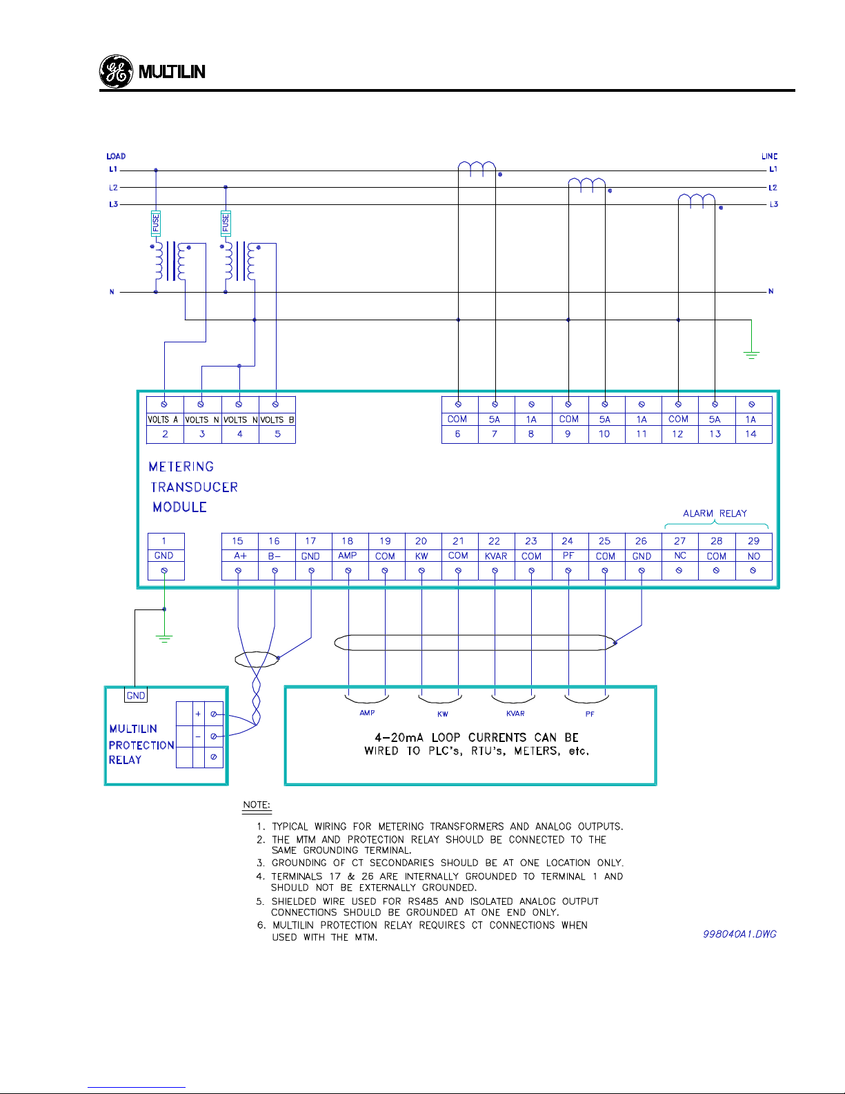
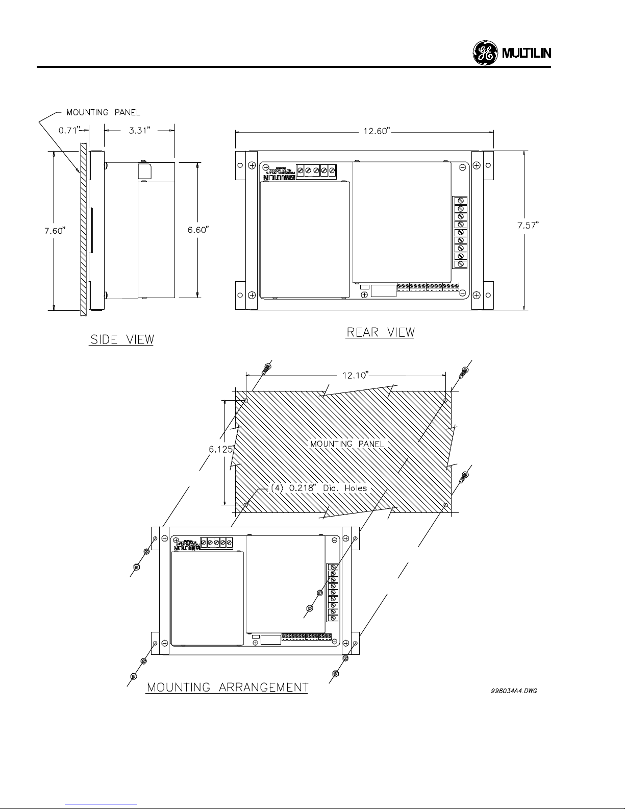
gives the 565/575 additional functionality. The mounting arrangement is shown in Figure 2.9 and the typical wiring for
PT’s and CT’s is shown in Figure 2.7A and Figure 2.7B.
Additional analog outputs can be wired as shown in Figure
2.8A and Figure 2.8B.
Hi-Pot Testing
The Relay has been tested at the factory for 1 second at
1800 VAC in order to verify its dielectric strength. Hi-pot
testing to ve rify the wiring into the gear
inner relay cradle removed from the outer case. JMP1 must
be removed bef ore Hi-pot testing. This jumper can be located
by viewing Figure 2.4.
Hi-pot testing should only be performed on the terminals
mentioned in the enclosed table of this addendum. With
these points in mind, here are the necessary steps for Hipotting a 565/575 Relay when wired into the gear.
must be done with the
1. Remove the 565/575 Relay inner chassis from the outer
case. Failure to remove the relay from the outer case can
cause failure of the relay.
2. Remove jumper JMP1 from the outer case’s rear
motherboard. Please see Figure 2.4 for this jumper’s
location.
3. Hi-pot the follo wing terminals with respect to surge ground
for 1 second at 1800 VAC:
#16
#29, #30, #31, #32
#42, #43, #44, #45, #46, #47, #48
#58, #59, #60, #61, #62, #63, #64
4. Ensure that jumper JMP1 is properly inserted after Hi-pot.
This should be on the two right most pins of the group of
three pins. If not, the unit will not be properly grounded.
5. Install the relay’s inner chassis into the outer case.
2-6
Figure 2.4 Removal of Hi-Pot Screw
Page 11

Table 2-1 - Terminal Identification
INSTALLA TION
Terminal Function
1 Ext. Switch #1 "+"
2 Ext. Switch #2 "+"
3 Ext. Switch #3 "+"
4 Ext. Switch #4 "+"
5 Ext. Switch #5 "+"
6 Ext. Switch #6 "+"
7 Ext. Switch #7 "+"
8 Ext. Switch #8 "+"
9 Breaker Open (52b) "+"
10 Breaker Common "–"
11 Breaker Closed (52a) "+"
12 Reclosure Enable "+"
13 Reclosure Common "–"
14 Reclosure Disable "+"
15 Block TC Common
16 Block TC N. O.
17 Analog Out "-"
18 Analog Out "+"
19 Analog Select A
20 Analog Select B
21 Analog Select C
22 Analog Select D
23 Analog In "-"
24 Analog In "+"
25 Trip Relay N.C.
26 Remote Trip "+ "
27 Remote Common "-"
28 Remote Close "+"
29 Block TC N. C.
30 ** Aux 4 Relay N.O.
31 ** Aux 4 Relay Common
32 ** Aux 4 Relay N.C.
33 ** Access Switch "+"
34 ** Access Switch "-"
35 Voltage Input V1
36 Voltage Input V2
}
575 only
575 only
Terminal Function
37 Voltage Input V3
38 Voltage Input Vn
39 43 Remote "+"
40 43 Remote "-"
41 Trip Relay N.O.
42 Close Relay Contact 1
43 Aux 1 Relay N.O.
44 Aux 2 Relay N.O.
45 Aux 3 Relay N.C.
46 Aux 1 Relay N.C.
47 Aux 2 Relay N.C.
48 Aux 3 Relay N.O.
49 Phase 1 Common
50 Phase 1 Input :5/:1
51 Phase 2 Common
52 Phase 2 Input :5/:1
53 Phase 3 Common
54 Phase 3 Input :5/:1
55 Ground Current Common
56 Ground Current Input :5/:1
57 Trip Relay Common
58 Close Relay Contact 2
59 Aux 1 Relay Common
60 Aux 2 Relay Common
61 Aux 3 Relay Common
62 Control Voltage GND
63 Supply Voltage "+"
64 Supply Voltage "-"
65 RS485 Por t "+"
66 RS485 Port "-"
67 MTM/RS485 Shield
68 ** MTM RS485 "+"
69 ** MTM RS485 "-"
70 IRIG-B
71 Analog Select Common
72 Ext. Switch Common
575 only
** 565 requires Option Card
2-7
Page 12
INSTALLATION
2-8
Figure 2.5 565 Relay Typical Wiring
Page 13
INSTALLA TION
Figure 2.6 Voltage Sensing Wire
2-9
Page 14
INSTALLATION
Figure 2.7A 565 with MTM CT and Open Delta VT Typical Wiring
2-10
Page 15
INSTALLA TION
Figure 2.7B 565 with MTM CT and Wye VT Typical Wiring
2-11
Page 16
INSTALLATION
Figure 2.8A Open Delta VT and CT MTM Typical Wiring
2-12
Page 17
INSTALLA TION
Figure 2.8B Wye VT and CT MTM Typical Wiring
2-13
Page 18
INSTALLATION
2-14
Figure 2.9 MTM Mounting Dimensions
Page 19
INSTALLA TION
Figure 2.10 565 Rear Panel Layout
2-15
Page 20

Page 21
Once the electrical connections have been made to the 565/
575 Relay and control power is applied, it is ready to be
programmed for the par ticular application. Any key referred
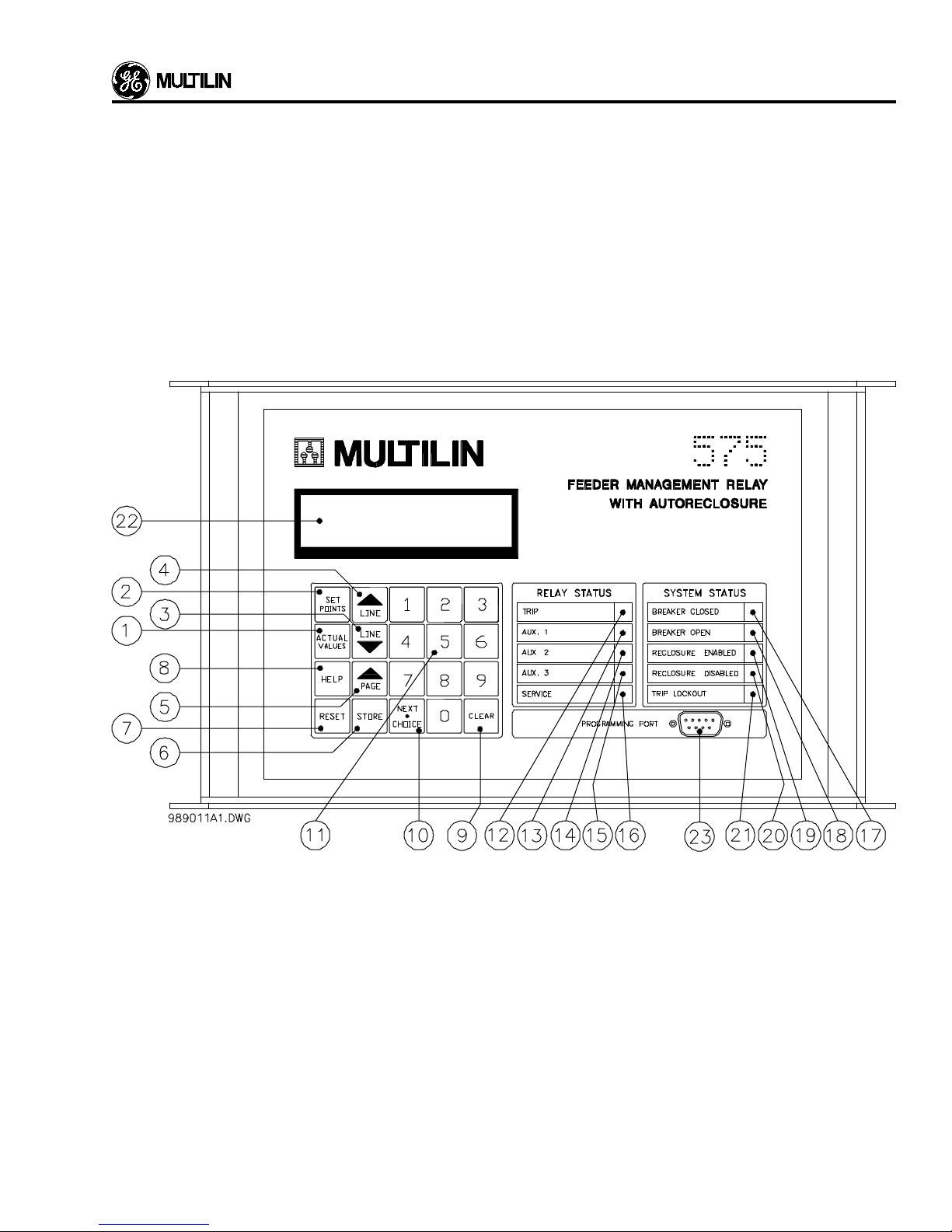
to in this section can be located in Figure 4.1, which shows
the keypad and front panel. If more information is needed
about any key or indicator, refer to the following pages which
describe the function and use of these.
Display Modes
DISPLAY AND KEYBOARD
can be read from the following message:
PHASE A CURRENT
710 A
The LINE DOWN key is then pressed again to view the next
message and so on to the last message of the page. When
the end of the page is reached, the following message will be
display ed:
The 565/575 Relay is capable of operating in three modes
and the display is used for viewing infor mation, in each of
these modes. The modes of operation are:
1. Actual Values mode.
2. Setpoints mode.
3. Help mode.
The information in modes 1 and 2 above is laid out in “book”
format, that is, each mode has a number of “pages” containing related information. Each page has “lines” containing a
message which can be read from the display. The lines are
read by entering the required mode by pressing the ACTUAL
VALUES, SETPOINTS, or HELP key and using the LINE UP
and LINE DOWN keys to view the lines.
Actual Values Mode
In actual values mode, any of the parameters monitored by
the 565/575 Relay can be viewed by the user. The message
lines in each page of this mode are shown and explained in
the Actual Values Mode section of this manual.
When this mode is entered, by pressing the ACTUAL VALUES key, the display will show the following message:
ACTUAL VALUES
CURRENT
This is the first line of page one. The remaining lines of page
one can be examined by using the LINE DOWN key. When
the last line of the page is reached, the PAGE key is used to
view the first line of page two. The LINE DOWN key can be
used to read each line of the page as before. This can be
repeated for all pages in the Actual Values mode. When the
last page is reached, pressing the PAGE key will return the
display to the first line of page one.
For example, as indicated ear lier, the first line of page one
shows:
CURRENT
END OF PAGE
The PAGE key can now be pressed to mov e to the first line of
the next page. The display will then show:
ACTUAL VALUES
ANALOG INPUT
The PAGE and LINE keys can now be used to view the
remaining lines in the Actual Values mode. Refer to the
Actual Values section for an explanation of each message.
If the relay is left in actual values mode and no key is pressed
for more than four minutes, the display returns to the default
line which is setup in actual values mode. The default display
will be the display which is visible during normal daily operation of the 565/575 Relay.
Setpoints Mode
This mode is used to view and enter the setpoints of the relay.
There are several pages of data, each of which contains
different information about the relay’s configuration, trip and
alarm settings. The lines in each page are shown in the
Setpoints Mode section of this manual. To place the relay in
setpoints mode, press the SETPOINTS key. The following
message will appear:
SETPOINTS
USER LEVEL
which is the first line of page one in setpoints mode. The LINE
UP and LINE DOWN keys can then be used to view the
individual lines in the setpoints mode. For example, if the
LINE DOWN key is pressed when the above message is on
display, the display changes to:
ACTUAL VALU E S
CURRENT
If the LINE DOWN key is now pressed, the phase A current
USER LEVEL
ADVANCED
which is the second line of page one of setpoints. When the
end of a page is reached, pressing the LINE DOWN key
3-1
Page 22
DISPLAY AND KEYBOARD
causes the following display:
USER LEVEL
END OF PAGE
This message indicates the end of the page and no more
lines are available. To move to the first line of the next page,
use the PAGE key.
If the relay is left in the setpoints mode with no key being
pressed for more than four minutes, the display changes to
the default page and line in actual values.
To enter or change setpoints a jumper or access key must
first be connected across terminals 33 & 34 and the setpoints
mode entered.
If an attempt is made to store a setpoint without enabling the
access terminals, the following message will appear:
ILLEGAL ACCESS
NEW SETPOINT
STORED
If the STORE key is not pressed the relay will keep the old
setpoint regardless of which choice is displayed.
The LINE DOWN key may now be used to move to the next
line of the setpoints page and further values entered as
described in the Setpoints Mode section.
When the end of a page in setpoints has been reached the
PAGE key can be used to view the setpoints on the next
page.
Help Mode
This display mode should be used whenev er help is required
in using the 565 relay. It is entered by pressing the HELP key
while the display is on any line in any page. The HELP k ey can
provide inf ormation about the currently displayed actual value
or setpoint message. Pressing the HELP key has no effect
when a flash message or HELP message is on the display.
and the setpoint will not be stored. This prevents unauthorized changing of setpoints. Stored values remain in the
Relay’s memory, even when control power is removed. The
ability of the relay to provide protection depends on the
values entered in the setpoints mode, theref ore these values
should be complete, accurate and ver y carefully entered.
Once a setpoint is displayed and the access jumper is
installed, it can be changed by either:
1. Entering new numerical values from the Keypad and
storing them in the relay’ s memory using the ST ORE k e y,
or
2. Making selections from a list of items using the NEXT
CHOICE key.
If the selection is to be made using the NEXT CHOICE key
then the 565/575 Relay will inform you by flashing the
following message on the bottom line of the display:
Use NEXT CH OICE
The possible choices will appear in the display one by one,
each time the NEXT CHOICE key is pressed. When the last
item in the list is reached pressing the key again will cycle the
display through the choices again.
Display the required choice and enter the value into the
Relay’s memory using the STORE key. The following message will appear for two seconds to indicate that the setpoint
has been stored by the Relay.
If the HELP key is pressed with the display on the first line of
page one the following message will appear:
PRESS ANY KEY
OR HELP
The user should then press the key for which instruction is
required or press the HELP key again to access infor mation
on the previously displayed actual value or setpoint message. When the desired key is pressed the display will show
the message:
PRESS LINE DOWN
TO SCRO LL
The LINE DOWN key can then be used to display the HELP
message which will give information about the line or key in
question.
If the HELP key is pressed while displaying any line other
than a page header the HELP message shown will relate to
the line which was displayed when the HELP key was pressed.
This applies when the 565/575 Relay is in actual values or
setpoints.
Pressing the CLEAR key at any time dur ing the help message will return the display to the page and line of the mode
in effect when the HELP key was originally pressed. The
ACTUAL VALUES and SETPOINTS keys m ay also be pressed
to exit HELP mode.
3-2
Page 23
DISPLAY AND KEYBOARD
Figure 4.1 565 Relay Front Panel
3-3
Page 24
DISPLAY AND KEYBOARD
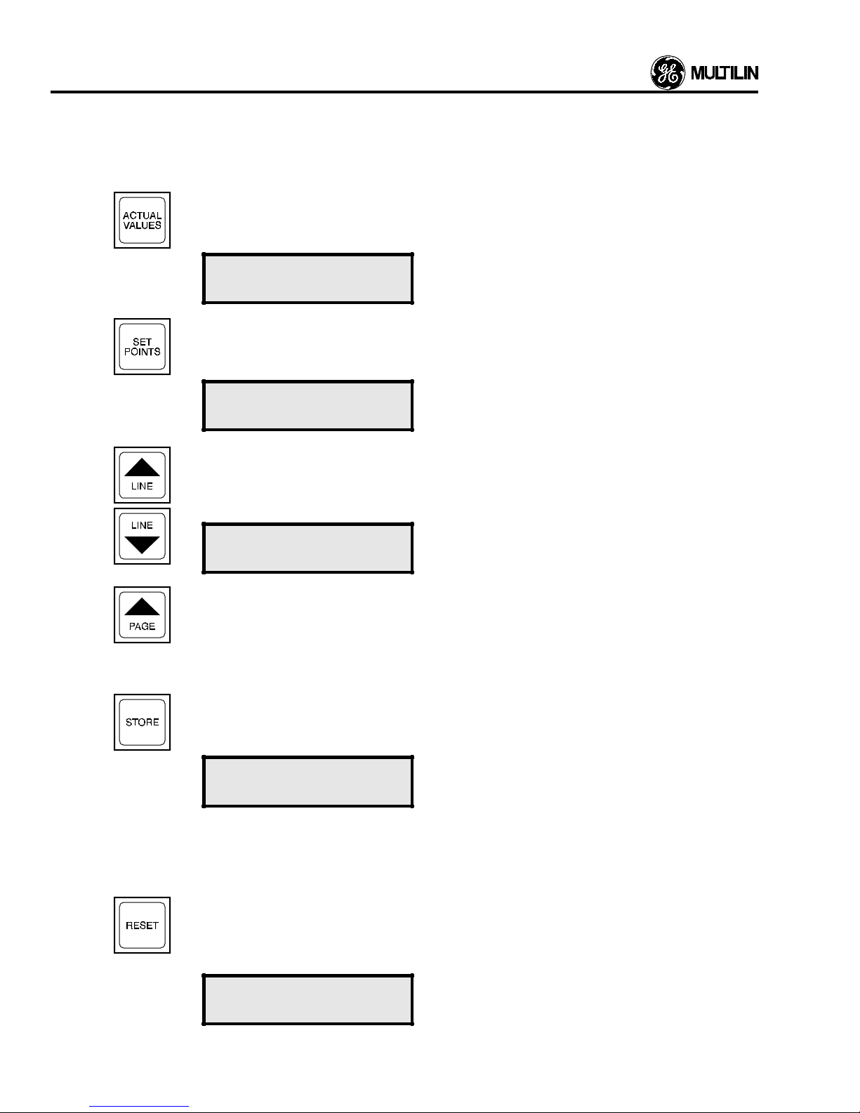
This section describes the front panel controls and indications. The “No.” column gives the number of each of the keys and
indications shown in Figure 4.1. The “Name” column shows the name of the key or indicator in question and the description
column gives infor mation about the use of the key or indicator.
Number Name Description
1
The ACTUAL VALUES key allows the user to examine all the information in the pages of actual
values described in the ACTUAL VALUES MODE section. Pressing this key causes the following
message to appear, which indicates the first line of page one of the Actual Values mode:
ACTUAL VALUES
CURRENT
2 The SETPOINTS key allows the user to examine and change all the user-programmable setpoints
in the pages of setpoint data as described in the SETPOINTS MODE section. Pressing this k e y will
cause this message to appear, also indicating the first line of page one of the Setpoints mode:
SETPOINTS
USER LE VEL
3,4 These keys allow the user to view the previous or next line of the current page, as indicated by the
arrow pointing up or down respectively. If either key is held pressed for more than two seconds then
the next or pre vious lines will be displayed at a fast rate. If the display already shows the last line of
any page then pressing the LINE DOWN key will cause the following message to be displayed:
END OF PA GE
5 The PAGE key allows the user to move from any line in a page to the first line in the next page. For
example, if y ou are currently viewing any line in page 2 of the Actual Values mode, pressing this ke y
will cause the display to move to the first line of page 3, Actual Values. If this key is pressed on the
last page of either Actual Values or Setpoints then the display will move to the first page of that
section. As with the LINE keys, holding down the PAGE key will cause the pages to be displayed
rapidly.
6
The STORE key is used to store all new setpoints in the 565/575 Relay’s memory. When this key is
pressed, the value being displayed will be stored as a new setpoint in the relay’s memory and the
following message will appear for 2 seconds (provided the Access jumper is installed):
NEW SETPOINT
STORED
The numeric keypad or the NEXT CHOICE ke ys are used to display the correct value as seen later.
The STORE key can only be used to store data within the ranges accepted by the 565/575 Relay.
It is also used to set the default display in actual values as described in the Actual Values Mode
section of this manual.
7 The RESET key returns the trip or any latched output relay to its inactive state and extinguishes the
associated LED after a fault condition has caused it to become active . This ke y will only be effective
if the fault condition has been removed. Otherwise, resetting will not be possible and pressing the
key will result in one the following messages:
RESET IMPOSSIBLE
FAULT PRESENT
3-4
Page 25
DISPLAY AND KEYBOARD
Number Name Description
RESET IMPOSSIBLE
ALARM PRESENT
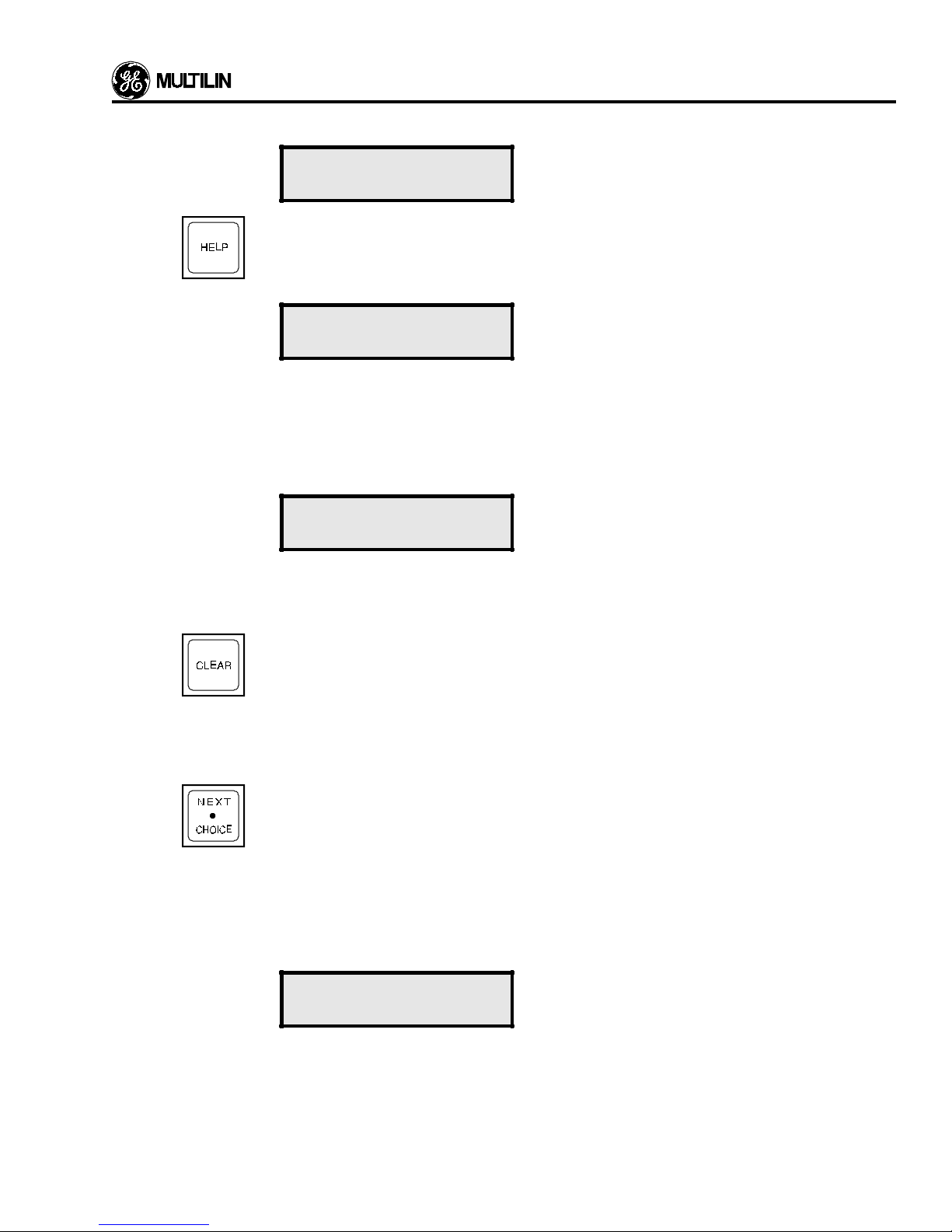
8 The HELP key provides the user with inf ormation on the function and use of each k ey on the ke ypad.
It also provides information about the currently displayed actual values or setpoints message. If
information is needed on the use of any of the keys on the keypad, use the LINE UP or PAGE key
to display the first line of any page . Then press the HELP k e y and the following message will appear:
PRES S ANY KEY
OR HELP
The user should then press the key for which instruction is required, for example, the PAGE key. If
information is needed on the previously displa yed actual values or setpoints message, press HELP
again.
The HELP key can also be pressed on an y line of either setpoints or actual values to get inf ormation
on that particular setpoint or actual value. If this is done the following message will appear :
PRESS LINE DOWN
TO SCROLL
9
10
Pressing LINE DOWN will allow the help message to be viewed. Pressing CLEAR will return the
display to the line where help was requested. Continue pressing LINE DOWN to display the entire
help message.
The CLEAR key perfor ms two functions.
1. In the setpoints mode, pressing this key will return an altered unstored setpoint to its original
value. This might be used if you keyed in an incorrect value and had not yet stored it. Once a
value is stored it cannot be altered using the CLEAR key.
2. In the Help mode the key allows the user to return to the previous display mode as described in
number 8.
This key, which also functions as the decimal point key is used to view a list of items which cannot
be shown on the display at once . Pressing the NEXT CHOICE key once will cause the first item from
the list to be displayed, pressing it again will displa y the second item, and so on. When the last item
is reached pressing the key will cause the first item to be displayed again. The entire list can thus
be viewed as many times as needed. The following example shows the use of the NEXT CHOICE
key.
For example, in Setpoints Mode page 3, the ground protection cur ve is chosen from a list of 5
curves. When this line is first read it will display the curve in use, the Extremely Inverse curve being
shown below.
GND O/C CURVE
SHAPE: EXTREM INV
To advise the user that the NEXT CHOICE key may be used to display other curves, the bottom line
of this display will change for two seconds, and the following display will be seen:
3-5
Page 26
DISPLAY AND KEYBOARD
Number Name Description
GND O/C CURVE
Use NEXT CHOICE
The display will then return to displa ying the Extremely Inverse curve. The other curves can now be
viewed one at a time by pressing the NEXT CHOICE key. For example, the Custom Curve will be
seen the next time the key is pressed as shown in the following display.
GND O/C CURVE
SHAPE: CUSTOM
The remaining curves can be viewed in the same way. The display will cycle through all the curves
as the key is pressed. Note that the curve in use by the 565/575 Relay will not be changed by
displaying the va rious choices. To change the curve in use, it must be displa y ed and stored. See the
STORE key description.
11 The Numeric keypad has the n umbers 0 to 9 and the decimal point. These k eys are used to enter
the numerical values of the various setpoints with or without a decimal. The decimal point key also
functions as the NEXT CHOICE key. In this case it is used to displa y one choice at a time from a list
of items. See NEXT CHOICE key description.
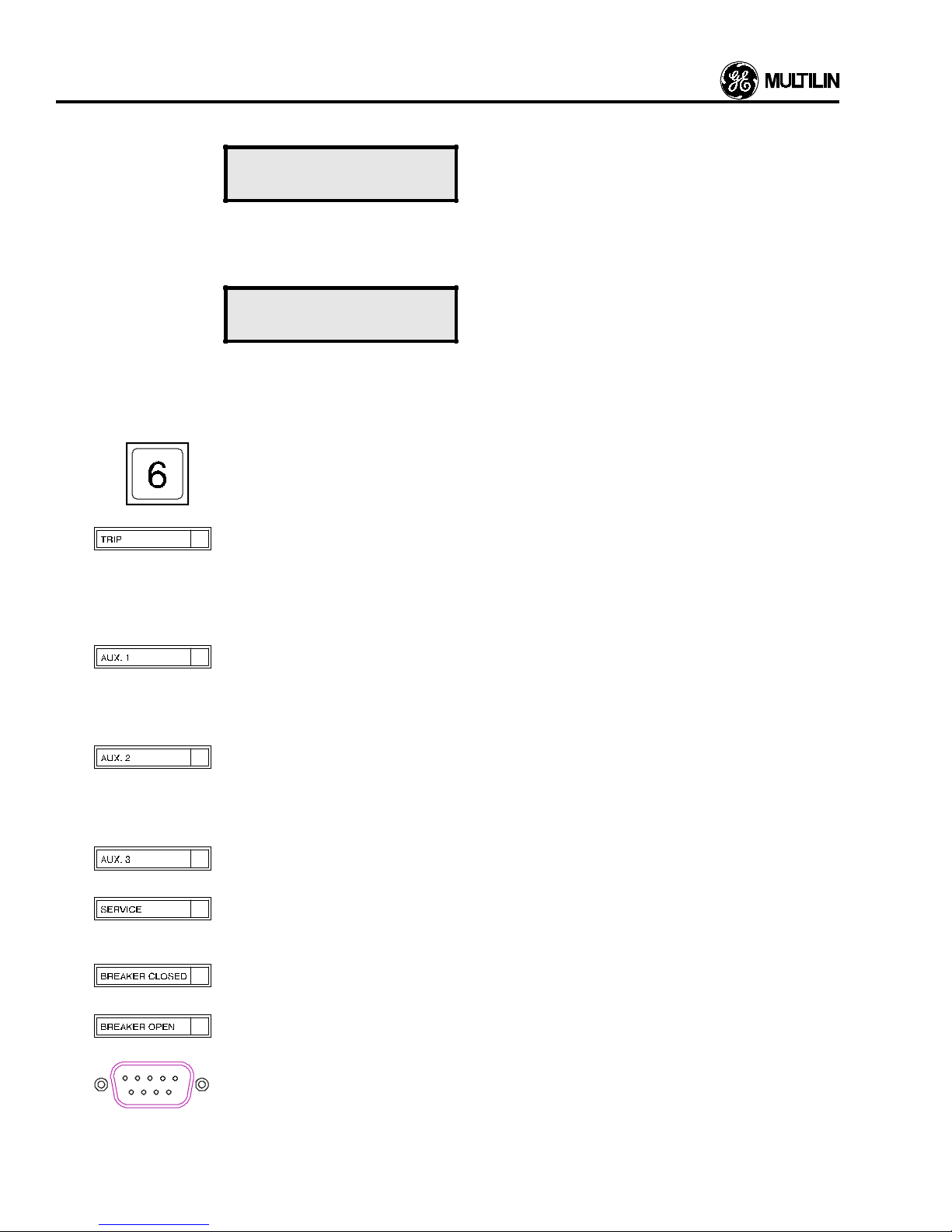
12 The Tri p LED indicates the state of the trip output relay which is used to trip the Feeder Breaker
monitored by the 565/575 Relay. When the LED is on, the Trip relay is active with the cause of the
trip condition shown on the LCD display. A flashing LED indicates that the relay was active, and has
returned to its inactive state. This can occur when the fault condition disappears and the relay is
programmed as pulsed. The LED will be extinguished by pressing the RESET key only if the fault
condition causing the relay to be activated has been removed.
13
14
15
16
17
18
19
The Aux 1 LED indicates the state of the output relay, Aux 1, which can be used for a function
chosen by the user. When the LED is on, the relay is active. If pulsed or unlatched operation is
chosen for this relay, the LED will flash if a trip condition is remo ved or will be e xtinguished when the
condition causing an alarm is removed. If latched operation is chosen the RESET key must be
pressed to return the relay to its no fault state and extinguish the LED indicator.
The Aux 2 LED indicates the state of the output relay, Aux 2, which can be used for a function
chosen by the user. When the LED is on, the relay is active. If pulsed or unlatched operation is
chosen for this relay, the LED will flash if a trip condition is remo ved or will be e xtinguished when the
condition causing an alarm is removed. If latched operation is chosen the RESET key must be
pressed to return the relay to its no fault state and extinguish the LED indicator.
The Aux.3 LED indicates the state of the output relay, Aux.3. When the LED is on, as during a trip
coil supervision alarm, the Aux 3 relay is inactive (cold coil).
If the Service LED illuminates steadily, the supply voltage may be too low. This LED may come on
momentarily when the 565/575 Relay is powered up. This is normal and does not indicate a fault
condition.
The Breaker Closed LED indicates the status of the Feeder Breaker being monitored by the 565/
575 Relay. The LED is on if the Feeder Breaker is closed.
The Breaker Open LED indicates the status of the Feeder Break er being monitored by the 565/575
Relay. The LED is on if the Feeder Breaker is open.
RS232 program port. This port allows for programming from a personal computer. When a cable is
connected to this port and the DTR line is pulled high, the rear RS485 communications por t is
disabled.
3-6
Page 27

Number Name Description
DISPLAY AND KEYBOARD
20
The display is a 32 character alphanumeric type. This display visually shows in English all values,
setpoints, and messages, through a series of lines within the pages of 3 display modes: Actual
Values, Setpoints, and Help.
3-7
Page 28

Page 29

All the messages displayed by the 565/575 Relay in the
actual values mode are listed and explained in this section.
As already seen, the messages are laid out in book form with
pages containing lines, each of which displays one message.
The 565/575 Relay has two user levels, “basic” and “advanced”. The messages seen depend on this user level,
which is chosen in page one of setpoints. The basic level
allows the user to operate the relay using the minimum of the
features necessary. The advanced level allows the user to
use all the 565/575 Relay features.
The advanced user sees all the messages shown. The
messages which will only be seen by the advanced user and
not the basic user are marked “L
The actual value mode has pages with the follo wing information:
”, for “Level-advanced”.
A
Page Contents
1. Current data.
2. Analog Input data.
3. Maintenance data.
4. Operations data.
5. Pretrip data.
6. Voltage and Frequency related data.
7. Event-Recording data.
8. Amps Demand Metering data.
9. MTM Metering data.
The numbers in the “Location” column to the left of each
message in this section give the page and line of that
message in the 565/575 Relay’s memory. For example, the
message to the right of A 1.3 in the “Location” column will
appear on page 1 and line 3 when the Relay is in actual
values Mode and is referred to as “message A 1.3”. If the
letters “L
indicates that the message will only appear if the advanced
user level is selected. The message will not appear if the
basic user level is selected.
The “Message Line” column shows the actual message
which can be read from the LCD display on the front panel of
the unit.
Quantities shown in display boxes are typical values only.
Different quantities will be displayed in each particular application.
Note: When finished viewing a message, press the LINE
DOWN ke y to view the next line. When the last line of a page
is reached, press the PAGE key to view the first line of the
next page.
” appear below a message in this column, this
A
ACTUAL VALUES MODE
Default Message Selection
The default message is the message which will be displayed
by the Relay under nor mal operating conditions. The display
will show the selected message if no key on the keypad is
pressed for more than four minutes and no alarm or trip
condition is present. Any message in actual values except
page headers, end of page markers, and messages A 3.2, A
3.7, A 4.9, A 7.4, A 7.9, A 7.10, A 8.6, A 8.10 and A 8.14 may
be selected as the default message. The above messages
cannot be used as their function is to allow data to be entered
into the Relay. To select any other message as the default
message, proceed as follows:
Use the PAGE key to select the page on which the required
message is located, in actual values, and use the LINE
DOWN k ey to display the message. Pressing the STORE k ey
will cause the following message to be displayed:
NEW DEFAULT
LINE SELECTED
The message selected is now the new default message.
Actual Values Message Abbreviations.
The following abbreviations are used in the actual values
messages:
A Amperes.
AC Access.
BRKR Breaker.
CL’D Cleared.
DEG C Degrees Celsius.
DEM’D Demand.
Hz Her tz.
INS Installed.
INST Instantaneous.
KA Kiloamps.
kVAR Kilovars.
kV Kilovolts.
kW Kilowatts.
MTM Metering Transducer Module.
MWHRS Megawatt Hours.
No. Number.
O/C Overcurrent.
PH Phase.
TEMP Temperature.
TRANS Transformer.
WNDG Winding.
When the last line of the last page in actual values is
reached, pressing the PAGE key will return the display to the
first page again.
4-1
Page 30

ACTUAL V ALUES MODE
Summary of Actual Value Page Contents
Page Contents Page Contents
1. Current Data.
Phase currents
Ground currents
2. Analog Input Data.
Analog input scaled values
3. Maintenance Data.
Breaker date
Breaker trips
Accumulated KA
4. Operations Data.
Timed phase overcurrent trips
Instantaneous phase overcurrent trips
Timed ground overcurrent trips
Inst. ground overcurrent trips
Overvoltage trips
Undervoltage trips
Analog input trips
8. Demand Metering Data.
Peak demand amps
Peak KW demand
Peak KVAR demand
9. Metering Data.
Power factor
MTM frequency
kW
kVAR
MWhrs
5. Pretrip Data.
Cause of present alarm
Cause of last trip
Phase trip current
Ground trip current
Phase trip voltage
Frequency at trip
Date of trip
Time of trip
6. Voltage Data.
Phase voltage
Frequency of feeder
7. Event Recording Data.
No. of events
View events
Events
Print events
Clear events
4-2
Page 31
Location Message Line Description
ACT U AL VALUES MODE - CURRENT
A 1.1
ACTUAL VALUES
The actual values page 1 header. This page gives information on the
feeder phase and ground currents being monitored by the 565 Relay.
CURRENT
A 1.2
PHASE A CURRENT
This is the actual monitored RMS current flowing in phase A of the feeder.
710 A
A 1.3
PHASE B CURRENT
This is the actual monitored RMS current flowing in phase B of the feeder..
715 A
A 1.4
PHASE C CURRENT
This is the actual monitored RMS current flowing in phase C of the feeder.
710 A
Message A 1.5 will only appear if Ground Sensing has been enabled in setpoints.
A 1.5
This is the actual leakage current flowing to ground in the system.
GROUND CURRENT
10 A
A 1.6
PHASES A= 710
This message allows all three phase currents to be displayed if they are
greater than 2% CT.
B= 715 C= 710
PHASES A< 2% CT
When the breaker is closed and the current is less than 2% of CT, the three
phase display will reflect this with “<2% CT”.
B<2% CT C< 2% CT
A 1.7
CURRENT
END OF PAGE
The last line of page 1, actual values. Press the PAGE key to view page 2.
4-3
Page 32
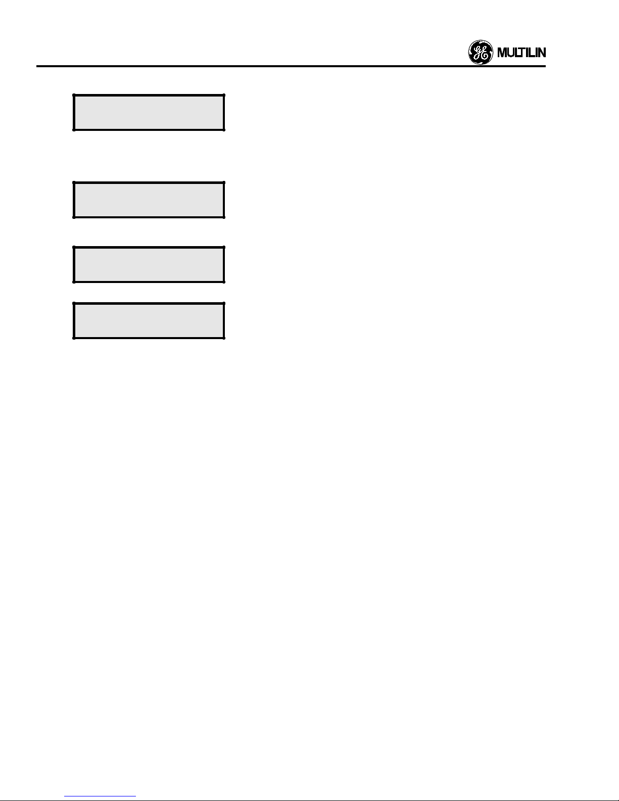
ACT UAL VALUES MODE - ANALOG INPUT
Location Message Line Description
A 2.1
ACTUAL VALUES
ANALOG INPUT
Message A 2.2 will only appear if Analog-In has been disabled in setpoints.
A 2.2
ANALOG INPUT
The actual values page 2 header. The 565/575 Relay can accept an analog
signal from 4 to 20 mA from any device such as a temperature monitor,
and provide trip or alarm signals at a user programmed value. The value of
this temperature, for example, is displayed in this page in whatever units
you select in the setpoints mode. Degrees Celsius are shown.
If Analog-In has been disabled in setpoints, this will be the only message
displayed.
DISABLED
Message A 2.3 will only appear if Analog In has been enabled in setpoints.
A 2.3
L
A
A 2.4
TRANS WNDG TEMP
87 DEG C
This is the present value of the analog signal being monitored by the Rela y,
if this option is used. In this example, the temperature of a transformer
winding is being monitored and degrees Celsius units have been chosen.
Other names and units can be selected, in setpoints mode.
The last line of page 2. Press the PAGE key to view page 3.
ANALOG INPUT
END OF PAGE
4-4
Page 33
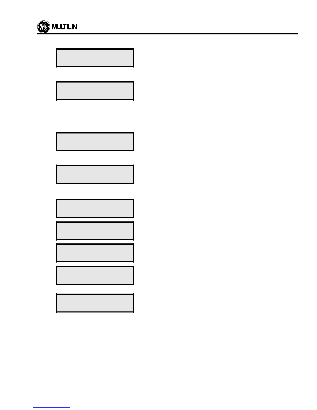
ACT U AL V ALUES MODE - MAINTENANCE DATA
Location Message Line Description
A 3.1
A 3.2
A 3.3
L
A
A 3.4
ACTUAL VALUES
MAINTENANCE DATA
BRKR mm/dd/yy
DATE AU G 23,1988
BREAKER TRIPS
79
ACCUMULATED KA
PHASE A 566
The actual values page 3 header. This page allows the maintenance
related data, which the Relay has collected, to be viewed. This data
remains in memory even if the control power is removed from the Relay.
Information on the number of breaker trips and accumulated breaker trip
current is stored on this page for use in scheduling breaker maintenance.
The new breaker in service date is entered here in the for m:
Month:Day:Year.
For example, if August 04, 1992 was the date then the following would be
entered:
08:04:92
This is the total number of times that the feeder circuit breaker controlled
by the Relay has been tripped since the breaker was put in service. The
maximum number of trips displayable is 10000. If the maxim u m n umber of
trips exceeds 10000, *** will be displayed. This figure may be useful for
scheduling mechanical inspections of the breaker.
This is the square of the Kiloamps feeder current measured right at the
time that the breaker delay rating has elapsed and the breaker is open.
This measurement is made at each trip of the breaker and added to the
previous accumulated value. This accumulated value gives an indication of
breaker pole wear and can be used to schedule inspections.
A 3.5
A 3.6
A 3.7
A 3.8
A 3.9
ACCUMULATED KA
PHASE B 568
ACCUMULATED KA
PHASE C 765
MAINTENANCE DATA
CLEAR? NO
DATA CL EARED
LAST:AUG 04,1992
MAINTENANCE DATA
END OF PAGE
This is the accumulated sum of the Kiloamps squared phase B current.
This is the accumulated sum of the Kiloamps squared phase C current.
This message asks if you want to clear the maintenance data which has
been collected to date. Use the NEXT CHOICE key to display YES or NO
and then store the value.
This is the date on which the maintenance data was last cleared in
message A 3.7. This date is automatically entered by the Relay, when the
data is cleared. All the maintenance data in this page has been collected
from the date shown here.
The last line of page 3, actual values. Press the PAGE key to view page 4.
4-5
Page 34
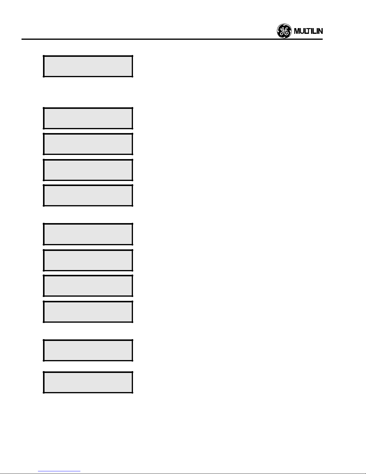
AC TUAL VALUES MODE - OPERATIONS DATA
Location Message Line Description
A 4.1
ACTUAL VALUES
OPERATIONS DATA
A 4.2
TIMED PHASE O/C
TRIPS 23
A 4.3
INST PH ASE O/C
TRIPS 5
A 4.4
TIMED GROUND O/C
TRIPS 45
A 4.5
INST GR OUND O/C
TRIPS 6
Messages A 4.6 and A 4.7 will only be shown if the Voltage feature has been enabled in Setpoints.
A 4.6
OVERVOLTAGE
TRIPS 3
The actual values page 4 header. This page allows the feeder operation
related data, which the Relay has collected, to be viewed. Information on
the number and types of trips issued by the Relay can be viewed in this
page. This data remains in memory even if the control power is removed
from the 565/575 Relay. The maximum number of trips which can be
displayed is 10,000. If the maximum number of trips exceeds 10,000, ***
will be displayed.
This is the number of times that the feeder breaker controlled by the 565/
575 Relay has been tripped due to the current flowing through it exceeding
the timed phase overcurrent level set up in the setpoints mode.
This is the number of times that the feeder breaker has been tripped by the
Relay due to the current in the three phase system exceeding the phase
instantaneous limits set up in the setpoints mode.
This is the number of times that the feeder breaker has been tripped by the
Relay due to ground current in the three phase system exceeding the
programmed level set up in the setpoints mode.
This is the number of times that the feeder breaker has been tripped by the
565 Relay due to the ground current exceeding the instantaneous limits
set up in the setpoints mode.
This is the number of times that the feeder breaker has been tripped by the
Relay due to an overvoltage exceeding the programmed level set up in
setpoints mode.
A 4.7
A 4.8
A 4.9
A 4.10
A 4.11
UNDERVOLTAGE
TRIPS 3
ANALOG INPUT
TRIPS 3
CLEAR OPERATIONS
DATA? NO
DATA CLEARED
LAST: AUG 04,1992
OPERATIONS DATA
END OF PAGE
This is the number of times that the feeder breaker has been tripped by the
Relay due to an undervoltage exceeding the programmed level set up in
setpoints mode.
This is the number of times that the feeder breaker has been tripped by the
Relay due to analog input exceeding the programmed level set up in
setpoints mode.
This message allows the user to clear the data in messages A 4.2 to 4.8.
To clear the data use the NEXT CHOICE key to select YES and then press
the STORE key. YES should only be selected if you are prepared to lose
the old data. The new data will be collected from the date that the clearing
was done. Select NO to continue using the old data.
This is the date when the operations data was last cleared in message A
4.9. This date is automatically entered by the Relay when the data is
cleared. This message can be referred to at an y time to check the date that
the present data collecting originated.
The last line of page 4, actual values. Press the PAGE key to view page 5.
4-6
Page 35
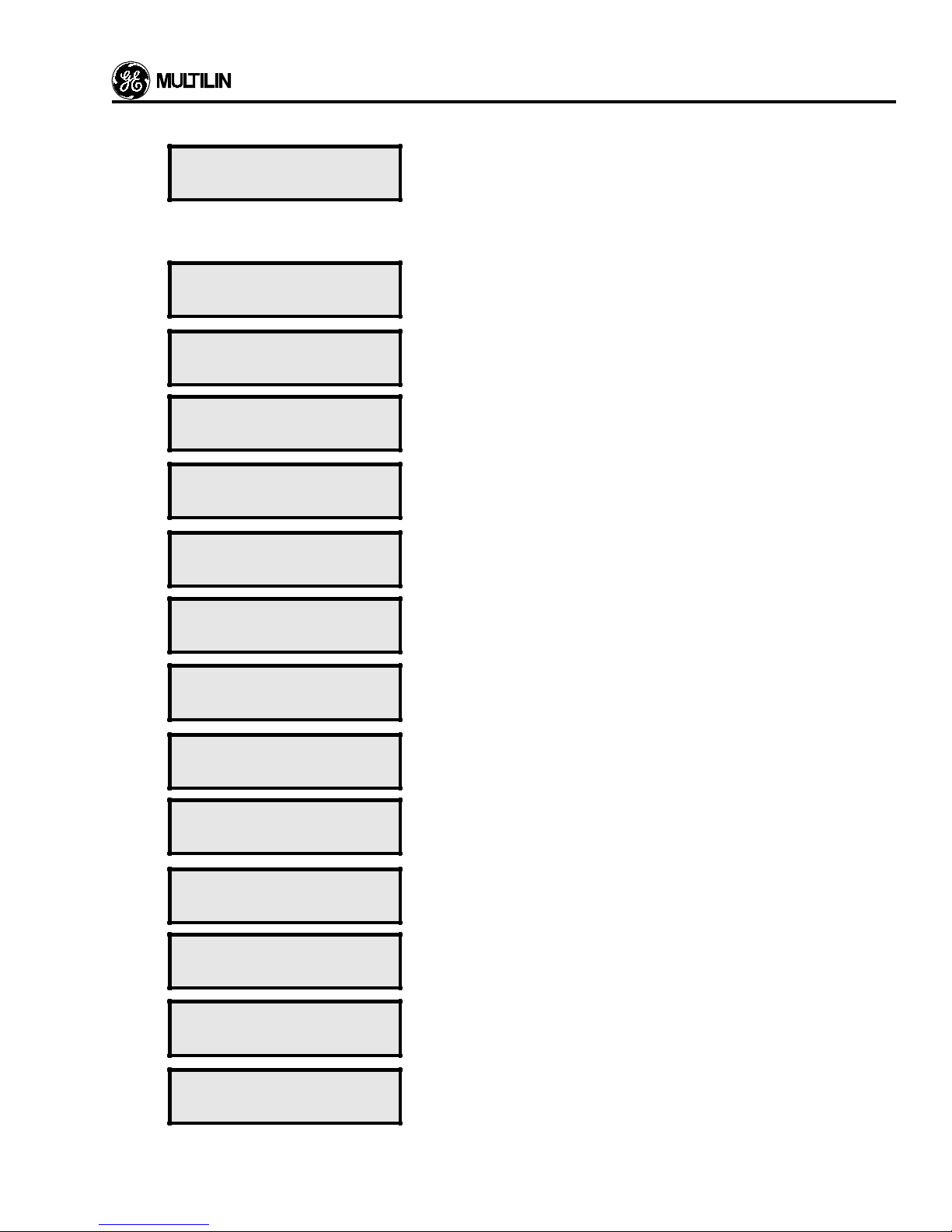
ACT U AL VALUES MODE - PRE-TRIP DAT A
Location Message Line Description
A 5.1
A 5.2
ACTUAL VALUES
PRE-TRIP DATA
ALARM: PHASE O/C
ALARM: GROUND
O/C
ALARM: OVERVOLT
ALARM: UNDERVOLT
ALARM: ANALOG
INPUT
The actual values page 5 header. This page displays the cause of the
current alarm and the cause of the last trip. It also gives data on the
condition of the feeder when a trip was last initiated by the 565/575 Relay.
This page can be viewed immediately after an alarm or trip to determine its
cause. Also, if an overcurrent trip has occurred, then the phase currents
can be inspected to check which phase or phases caused this.
This message will only appear if the condition causing the alarm is present.
In this case the current in any or all of the phases is exceeding the phase
alarm limit set up in setpoints mode.
This message indicates that the present alarm is caused by the ground
current exceeding the limits specified in setpoints mode.
This message indicates that the present alarm is caused by the voltage
sensed between phases or between a phase and the neutral line rose
above the limits specified in setpoints mode.
This message indicates that the present alarm is caused by the voltage
sensed between phases or between a phase and the neutral line dropped
below the limits specified in setpoints mode.
This message indicates that the present alarm is caused by the analog
input exceeding the limits specified in setpoints mode.
ALARM:
ACCUMULATED KA
SWITCH ALARM 1
ALARM: AMPS
DEMAND
ALARM: KW DEMAND
ALARM: KVAR
DEMAND
ALARM: POWER
FACTOR
ALARM: FREQUENCY
This message indicates that the present alarm is caused by the Accumulated KA exceeding the limits specified in setpoints mode.
This message indicates that the present alarm is caused by the external
switch programmed to create a Definite Time alarm.
This message indicates that the present alarm is caused by the Amps
Demand exceeding the limits specified in setpoints mode.
This message indicates that the present alarm is caused by the kW
Demand exceeding the limits specified in setpoints mode.
Option Card **
This message indicates that the present alarm is caused by the kVAR
Demand exceeding the limits specified in setpoints mode.
Option Card **
This message indicates that the present alarm is caused by the MTM
Power Factor exceeding the limits specified in setpoints mode.
requires Option Card **
This message indicates that the present alarm is caused by the MTM
Frequency exceeding the limits specified in setpoints mode.
quires Option Card **
** 565 requires
** 565 requires
** 565
** 565 re-
ALARM: BR EAKER
DISCREPANCY
This message indicates that the present alarm is caused by the feeder
breaker not responding within the time limit specified in setpoints mode.
4-7
Page 36
ACT UAL VALUES MODE - PRE-TRIP DATA
Location Message Line Description
A 5.3
A 5.4
ALARM: TRIP COIL
ALARM: MTM COMM
CAUSE OF LAST
TRIP:
TIME OV ERCURRENT
PHASE A B C
TIME OVERCURRENT
GROUND
INST OVERCURRENT
PHASE B
INST OVERCURRE NT
GROUND
This message indicates that the present alarm is caused by an open in the
trip coil circuit.
This message indicates that the present alarm is caused by failure in MTM
communications.
This message appears on the display for 2 seconds to advise the user that
the cause of the last trip will be displayed next. It will then disappear to be
replaced by the next message which will give the reason for the last trip of
the feeder breaker. One of the following messages will then be displayed.
This message indicates that the feeder breaker trip was caused by the
current in any or all of the phases A, B or C of the feeder exceeding the
phase time/overcurrent limits programmed in the setpoints mode. Phases
A, B and C are shown here.
This message indicates that the trip was caused by the ground current
sensed by the 565 Relay exceeding the limits set by the timed/overcurrent
curve which was programmed in the setpoints mode.
This message indicates that the trip was caused by the current in any or all
of the phases A, B or C exceeding the instantaneous limit set up in
setpoints mode. Phase B is shown here.
This message indicates that the feeder breaker was tr ipped due to the
ground current exceeding the instantaneous setpoint entered in setpoints
mode.
** 565 requires Option Card **
** 565 requires Option Card **
UNDERVOLTAGE
FAULT
OVERVOLTAGE
FAULT
EXTERNAL TRIP #1
SWITCH 3
ANALOG IN PU T
TRANS WNDG TEMP
POWER FACTOR
FAULT
FREQUENCY
FAULT
This message indicates that the voltage sensed between phases or
between a phase and the neutral line dropped below the under voltage
limits set in setpoints mode, causing a feeder breaker trip.
This message indicates that the voltage sensed between phases or
between a phase and the neutral line rose above the overvoltage limits set
in setpoints mode, causing a feeder breaker trip.
This message indicates which of four external trips, indicated by the switch
named, caused the breaker to trip. There are eight user programmable
switches named SW.1 to SW.8. Each of these may be assigned to one
external trip.
This display indicates that the trip was caused by the analog input to the
565 Relay exceeding the limits specified in setpoints mode. If a name was
assigned to this analog input in setpoints mode, then this name will appear
in the message. A typical user-assigned name, “TRANS WNDG TEMP”
indicating a transformer winding temperature is shown for example.
This message indicates that the trip was caused by the MTM power factor
exceeding the limits specified in the setpoints mode.
Option Card **
This message indicates that the trip was caused by the MTM frequency
exceeding the limits specified in the setpoints mode.
Option Card **
** 565 requires
** 565 requires
4-8
Page 37

ACT U AL VALUES MODE - PRE-TRIP DAT A
Location Message Line Description
A 5.5
PHASE A PRE-TRIP
This is the RMS current flowing in phase A measured over one cycle of
feeder current, at the time that the 565/575 Relay initiated the breaker trip.
CURRENT 16100 A
A 5.6
A 5.7
PHASE B PRE-TRIP
CURRENT 15900 A
PHASE C PRE-TRIP
This is the RMS current flowing in phase B measured over one cycle of
feeder current, at the time that the 565/575 Relay initiated the breaker trip.
This is the RMS current flowing in phase C measured over one cycle of
feeder current, at the time that the 565/575 Relay initiated the breaker trip.
CURRENT 16200 A
A 5.8
GROUND PRE-TRIP
CURRENT 250 A
Messages A 5.9 to 5.11 will only appear if an Open Delta system is chosen in Setpoints mode.
A 5.9
PRE-TRIP VOLTAGE
This is the RMS ground current sensed by the Relay measured over one
cycle of feeder current, at the time when the 565/575 Relay initiated the
breaker trip.
This is the voltage between phases A and B when the 565 Relay caused
the feeder breaker to trip due to a system fault.
A-B 13.80 kV
A 5.10
PRE-TRIP VOLTAGE
This is the voltage between phases B and C when the 565/575 Relay
caused the feeder breaker to trip due to a system fault.
B-C 13.80 kV
A 5.11
PRE-TRIP VOLTAGE
This is the voltage between phases C and A when the 565/575 Relay
caused the feeder breaker to trip due to a system fault.
C-A 13.80 kV
Messages A 5.12 to 5.14 will only appear if a Wye system is chosen in Setpoints mode.
A 5.12
PRE-TRIP VOLTAGE
This is the voltage between phase A and the neutral line when the 565/575
Relay caused the feeder breaker to trip due to a system fault.
A-N 7.85 kV
A 5.13
PRE-TRIP VOLTAGE
This is the voltage between phase B and the neutral line when the 565/575
Relay caused the feeder breaker to trip due to a system fault.
B-N 7.85 kV
A 5.14
PRE-TRIP VOLTAGE
This is the voltage between phase C and the neutr al line when the 565/575
Relay caused the feeder breaker to trip due to a system fault.
C-N 7.85 kV
A 5.15
L
A
A 5.16
FREQUENCY AT
TRIP 60.2 Hz
DATE OF TRIP
This is the feeder frequency, measured in Hz, at the time when the 565/
575 Relay caused the breaker to trip. If an MTM is communicating with the
565/575 at the time of the trip, the frequency recorded will be from the
MTM.
This is the date when the 565/575 Relay last tripped the feeder breaker
due to a system fault.
AUG 04 ,1992
A 5.17
TIME OF TRIP
This is the time when the 565/575 Relay last tripped the feeder breaker. It
is laid out in the following form:
14:20:42
Hour:Minute:Second
4-9
Page 38

ACT UAL VALUES MODE - PRE-TRIP DATA
Location Message Line Description
A 5.18
PRE-TRIP DATA
END OF PAGE
The last line of page 5, actual values. Press the PAGE key to view page 6.
4-10
Page 39
AC TU AL VALUES MODE - VOLT AGE
Location Message Line Description
Messages A 6.1 to 6.9 will only appear if voltage sensing has been enabled in setpoints mode.
A 6.1
ACTUAL VALUES
VOLTAGE
Messages A 6.2 to 6.4 will only appear if an Open Delta system is chosen in Setpoints mode.
A 6.2
VOLTAGE A-B
The actual values page 6 header. This page giv es values of the v oltage and
frequency of the three phase feeder being monitored by the 565/575
Relay.
The voltage between phases A and B of the f eeder being monitored by the
565/575 Relay.
4.16 kV
A 6.3
VOLTAGE B-C
The voltage between phases B and C of the f eeder being monitored by the
565/575 Relay.
4.16 kV
A 6.4
VOLTAGE C-A
The voltage between phases C and A of the f eeder being monitored by the
565/575 Relay.
4.16 kV
Messages A 6.5 to 6.7 will only appear if a Wye system is chosen in setpoints mode.
A 6.5
VOLTAGE A-N
The voltage between phase A and the neutral line of the feeder being
monitored by the 565/575 Relay.
2.30 kV
A 6.6
VOLTAGE B-N
The voltage between phase B and the neutral line of the feeder being
monitored by the 565/575 Relay.
2.30 kV
A 6.7
VOLTAGE C-N
The voltage between phase C and the neutral line of the feeder being
monitored by the 565/575 Relay.
2.30 kV
The following message will be displayed if no Metering Transducer Module (MTM) has been connected. If a MTM is used and
an Option Card is installed, see METERING DATA page in Actual Values for frequency reading.
A 6.8
A 6.9
FREQUENCY OF
FEEDER 60.1 Hz
VOLTAGE
This is the frequency of the feeder voltage being monitored by the 565/575
Relay. The frequency measurements are also enhanced. They are accurate to better than 0.1% of nominal frequency (0.05 Hz). Displayed data
resolution is now 0.01 Hz.
The last line of page 6, actual values. Press the PAGE key to view page 7.
END OF PAGE
4-11
Page 40
ACT UAL VALUES MODE - EVENT
Location Message Line Description
A 7.1
ACTUAL VALUES
The Actual Values page 7 header. This page allows the recorded events to
be viewed.
EVENT
* NOTE: See Section 7 for more infor mation on Event Recording.
Message A 7.2 will only appear if event recording has been disabled in setpoints.
A 7.2
EVENT RECORDING
This message is used to inform the user that event recording has been
disabled.
DISABLED
Messages A 7.3 to A 7.11 will only appear if event recording has been enabled in the setpoints mode.
A 7.3
NO. OF EVENTS:
This message shows the number of recorded events.
XX
A 7.4
A 7.5
VIEW EV ENTS?
NO
## EVENT CAUSE
t mm/dd/yy hh:mm
This message asks if the user wants to view events. Use the NEXT
CHOICE key to display YES or NO and press STORE to select the choice.
If YES is selected, the event template will appear for 2 seconds. Following
this, the first event will be displayed. Viewing of Event Recorder data is in
natural order — last event is first viewed.
Event template: The top line shows the event number and the cause of
event fields. The second line shows the event type, date and time fields .
A 7.6
A 7.7
A 7.8
A 7.9
A 7.10
01 PH-A TIME O/C
T 04/19/90 22:30
02 UNDERVOLTAGE
A 04/19/90 22:31
03 AC JUMPER INS
O 04/20/90 11:15
04 SERIAL TRIP
O 03/17/94 11:14
05 SERIAL CLOSE
O 03/17/94 11:15
This message shows an example of a trip event - Phase A Timed
Overcurrent Trip, occurred at 10:30pm on April 19, 1990. Press LINE
DOWN key to display the next event.
This message shows an example of an alarm event - Undervoltage Alarm.
This message shows an example of “other” event - Access Jumper
Installed.
This message shows an example of "other" event - Serial Trip. This
message is displayed if the breaker is closed when the 565/575 receives
the Modbus Serial Trip command. If the breaker is open when this Serial
Trip command is issued, it will be ignored.
This message shows an example of "other" event - Serial Close, if the
breaker is open when the 565/575 receives the Modbus Serial Close
command. If the breaker does not close successfully within the breaker
discrepancy delay time, a breaker discrepancy will be declared. If the
breaker is closed when this Serial Close command is issued, it will be
ignored.
In order to prevent conflicts with the Remote Trip/Close commands via
hardware, the communication commands will only function if the Remote/
Local switch at terminals #39 and #40 is in the "open" Local position.
A 7.11
PRINT EVENTS?
NO
4-12
After all the events are viewed, pressing LINE DOWN key will show this
message, which asks users if event printout is desired. Press NEXT
CHOICE key to toggle YES or NO options and press STORE key to select
it. (N OTE: Pr inter is presumably connected to the rear RS232 port). Press
Page 41
Location Message Line Description
LINE DOWN k ey to continue to the next message.
ACT U AL VALUES MODE - EVENT
A 7.12
A 7.13
A 7.14
CLEAR EVENTS?
NO
EVENTS CL EARED
LAST:AUG 04,1992
EVENTS
END OF PAGE
This message prompts the user to erase the event data displayed on this
page.
This message shows users when events were last cleared.
The last line of EVENT page. Press the PAGE key to view page 8.
4-13
Page 42
AC TUAL VALUES MODE - DEMAND DATA
Location Message Line Description
A 8.1
ACTUAL VALUES
The actual values page 8 header. This page allows the demand metering
related data to be viewed.
DEMAND DATA
Message A 8.2 will only appear if AMPS DEMAND is disabled in setpoints.
A 8.2
L
A
Messages A 8.3 to A 8.5 will only be shown if the Amp Demand feature has been enabled in setpoints.
A 8.3
AMPS DE MAND
DISABLED
PH-A PE AK DEMAND
This message informs the user that Amps Demand has been disabled.
This message shows the peak amps demand value of phase A since the
last clearing of the function data.
1050 A
A 8.4
A 8.5
PH-B PE AK DEMAND
1100 A
PH-C PE AK DEMAND
This message shows the peak amps demand value of phase B since the
last clearing of the function data.
This message shows the peak amps demand value of phase C since the
last clearing of the function data.
1070 A
A 8.6
CLEAR AMP DEMAND
This message prompts the user if Demand Amps data is to be cleared. If
YES, data stored will be erased.
DATA? NO
A 8.7
DATA CL EARED
This message shows users when data was last cleared.
LAST:AUG 04,1992
The following messages are only displayed if a Metering Transducer Module (MTM) has been connected to the 565/575, an
Option Card has been installed in the 565, and the communications has been enabled.
Message A 8.8 will appear only if the KW Demand feature has been disabled.
A 8.8
KW DEMAND
This message informs the user the KW Demand has been disabled.
DISABLED
Message A 8.9 will only appear if the KW Demand feature has been enabled.
A 8.9
PEAK KW DEMAND
This message shows the peak kW demand value since the last clearing.
65000 kW
A 8.10
CLEAR KW DEMAND
This prompts the user if kW demand data is to be cleared. If YES, data
stored will be erased.
DATA? NO
A 8.11
KW DE MAND DATA
This message shows the date when data was last cleared.
CL'D:AUG 04,1992
4-14
Page 43
ACTUAL V ALUES MODE - DEMAND DAT A
Location Message Line Description
Message A 8.12 will only appear if KVAR Demand has been disabled in setpoints.
A 8.12
KVAR DEMAND
This message informs the user that KVAR Demand has been disabled.
DISABLED
Message A 8.13 will only appear if the KVAR Demand feature has been enabled.
A 8.13
PEAK KVAR DEMAND
This message shows the peak kVAR demand value since the last clearing.
65000 kVAR
A 8.14
A 8.15
CLEAR KVAR DEM'D
DATA? NO
KVAR DEMAND DATA
This prompts the user if kVAR demand data is to be cleared. If YES, data
stored will be erased.
This message shows the date when data was last cleared.
CL'D:AUG 04,1992
A 8.16
DEMAND DATA
The last line of DEMAND DATA page. Press the PAGE key to view page 9.
END OF PAGE
4-15
Page 44
ACT UAL VALUES MODE - METERING DATA
Location Message Line Description
*** Available only with Option Card installed **
A 9.1
ACTUAL VALUES
The Actual Values page 9 header. This page allows the metering data to be
vie w ed.
METERING DATA
Messages A 9.2 to A 9.6 will only appear if the Metering Transducer Module (MTM) has been enabled in setpoints.
A 9.2
POWER FACTOR
The Power Factor is displayed during this message.
LAGGING 0.75
A 9.3
FREQUENCY MTM
This message displays the frequency.
60.1 Hz
A 9.4
REAL PO WER
This message displays the current real power delivered. If communicating
with a rev. E MTM or MTM Plus, the kW polarity sign will be included.
65 000 kW
A 9.5
REACTIVE POWER
This message displays the current reactive power. If communicating with a
rev. E MTM or MTM Plus, the kW polarity sign will be included.
65000 kVAR
A 9.6
ENERGY USED
This message displays the real power used.
65000 MWHRS
A 9.7
CLEAR ENERGY
USED DA TA? NO
This prompts the user if Energy Used Data is to be cleared. If YES, data
stored will be erased. The MWhrs should be cleared after 65,000 in order
to ensure safe operation.
A 9.7
METERING DATA
END OF PAGE
MWh data on MTM can be cleared now by using 565/575 Relay's keypad
or Modbus communication command.
The last line of METERING DATA page. This is the last page of ACTUAL
VALUES.
4-16
Page 45

All the messages displayed b y the 565 Relay in the setpoints
mode are shown and explained in this section. As for actual
values, the messages are laid out in book form with a number
of pages. Each page contains lines displaying a message.
The setpoints section has several pages, the contents of
which are as follows:
Page Contents
SETPOINTS MODE
6. Aux 1&2
7. Trip & Aux 1&2
The relay(s) to be activated can be displayed b y pressing the
NEXT CHOICE key. The display will show one of the options
above, each time the key is pressed. When the last item is
reached, the display will go back to the first item the next time
the NEXT CHOICE key is pressed.
1. User Level setpoints.
2. Phase Current setpoints.
3. Ground Current setpoints.
4. Configuration setpoints.
5. Analog Input setpoints.
6. Analog Output setpoints.
7. Communications setpoints.
8. Calibration Mode setpoints.
9. Voltage setpoints.
10. Demand Metering setpoints.
11. MTM Metering setpoints.
The numbers in the “Location” column to the left of each
message in this section give the page and line of that
message in the 565 Relay’s memory. For example, the
message to the right of the number S 1.2 in the “Location”
column will appear on page 1 and line 2 when the Relay is in
setpoints mode. The “Message Line” column shows the
actual message which can be read from the LCD display on
the front panel of the unit. The 565 Relay has two user le vels,
“basic” and “advanced”. The messages seen depend on this
user level, which is chosen in page one of setpoints. The
basic level allows the user to operate the relay using the
minimum of the features necessary. The advanced level
allows the user to use all the 565 Relay features.
The messages which will only be seen by the advanced user
L
and not the basic user, are marked “
vanced” in the Location column.
Quantities shown in display boxes are typical values only.
Different quantities will be displayed in each particular application.
”, for “Level-ad-
A
Relay Selection
The 565/575 Relay has six internal relays. They are called
Trip, Close, Aux. 1, 2, 3, and 4. The following are the combinations of relays which you can select to have activated by
any alarm or trip condition. This selection must be made in
the setpoints mode.
ALARM RELAY TRIP RELAY
SELECTION SELECTION
1. Aux 1 1. Trip
2. Aux 2 2. Aux 1 (565 only)
3. Aux 1&2 (565 only) 3. Aux 2 (565 only)
4. Trip & Aux 1
5. Trip & Aux 2 (565 only)
For example, say a combination of relays is being assigned
to the undervoltage trip condition in setpoints. If the T r ip rela y
and Auxiliary 1 relay need to be activated by this condition,
the NEXT CHOICE key is pressed until the display shows
UNDERVOLT TRIP
RELAY TRIP&AUX1
The STORE key is then pressed to store the selected relay or
combination of relays in the 565/575 Relay’s memory. The
following message will appear for two seconds to verify that
this has been done.
NEW SETPOINT
STORED
When more than one relay is selected as shown, all the
selected relays will be energized simultaneously. The contacts of the selected relay(s) can then be used to provide
remote alarms or t rips. These contacts are available at the
rear of the 565 Relay panel. See the wiring diagram for
terminal numbers.
Setpoint Message Abbreviations
The following abbreviations are used in the messages in the
setpoints pages:
A Ampere
AL’M Alarm
AUX Auxiliary
COMM Communications
CT Current Transformer
CURR Current
CYC Cycles
DISCREP. Discrepancy
EXTREM Extremely
FREQ Frequency
GND Ground
Hz Hertz
INST Instantaneous
INV Inverse
KA Kiloamps
KV Kilovolts
KVAR Kilovars
KW Kilowatts
LCD Liquid Crystal Display
mA Milliamps
5-1
Page 46

SETPOINTS MODE
MAX Maximum
MIN Minimum, or Min utes
MOD Moderately
mS Milliseconds
MTM Metering Transducer Module
O/C Overcurrent
OVERVOLT Overvoltage
P/F Power Factor
REV Revision
SEC Secondar y, or Second
SW Switch
UNDERVOLT Undervoltage
VOLTS Voltage
VT Voltage Transformer
× P/U Multiple of Pickup Level
ZERO SEQ Zero Sequence
5-2
Page 47

Summary of Setpoint Page Contents
Page Contents Page Contents
SETPOINTS MODE
1. User Level setpoints.
User level
Security Feature/Access code
2. Phase Current setpoints.
Phase CT primar y rating
Phase overcurrent pickup level
Phase overcurrent curve shape
Phase overcurrent time dial
Phase overcurrent trip relay
Phase overcurrent alarm
Phase instantaneous trip (565 only)
Phase custom curve trip times (565 only)
Phase HISET instantaneous trip (575 only)
Phase autoblock HISET (575 only)
Phase LOSET instantaneous trip (575 only)
Phase custom curves 1 trip times (575 only)
3. Ground Current setpoints.
Ground sensing system
Ground CT primary rating
Ground overcurrent pickup level
Ground overcurrent curve shape (565 only)
Ground overcurrent curve 1 shape (575 only)
Ground overcurrent time dial (565 only)
Ground overcurrent time dial 1 (575 only)
Ground overcurrent trip relay
Ground overcurrent alarm
Ground instantaneous trip (565 only)
Ground HISET instantaneous trip (575 only)
Ground autoblock HISET (575 only)
Ground LOSET instantaneous trip (575 only)
Ground autobloc k LOSET (575 only)
Ground custom curve trip times
Ground custom curve 1 trip times (575 only)
5. Analog Input setpoints.
Analog input title and units
Min and max current scale values
Analog input trip
Analog input alarm
6. Analog Output setpoints.
Analog output parameters
Analog output range
7. Communications setpoints.
Relay address
Baud rate
8. Calibration Mode setpoints.
Exercise relay
Status of switch inputs
LCD display contrast
Multilin 565 Relay Revision
9. Voltage setpoints.
VT connection
VT nominal secondary volts
VT primary volts
Zero volts detect
Undervoltage trip
Undervoltage alarm
Overvoltage trip
Overvoltage alarm
10. Demand Metering setpoints.
4. Configuration Setpoints.
Clock
Switch contact functions
Switch contact configurations
Relay assignments
Breaker response delay
Breaker discrepancy delay
Trip coil supervision
Accumulated KA
Event recording
Event printing
Cold load P/U delay
MTM communications enable
Amps demand
KW demand
KVAR demand
5-3
Page 48

SETPOINTS MODE
Summary of Setpoint Page Contents
Page Contents Page Contents
11. MTM Metering setpoints.
MTM communications alarm
MTM CT select
MTM CT primar y rating
Power factor alarm
Power factor trip
Frequency alarm
Frequency trip
MTM scaling factor
Voltage reversal trip
12. Auto Reclosure setpoints. (575 only)
Number of reclosure shots
Shot dead times
Scheme reset time
Reclosure enable relay
13. Phase Curves setpoints. (575 only)
Phase curve changeover time
Phase overcurrent curve 2 shape
Phase overcurrent time dial 2
Phase custom curve 2 trip times
14. Ground Curves setpoints. (575 only)
Ground curves setpoints
Ground overcurrent curve 2 shape
Ground overcurrent time dial 2
Ground custom curve 2 trip times
5-4
Page 49

SETPOINTS MODE
Setpoint Name Factor y Default Range Step
1. User Level setpoints.
User Level Advanced. Basic/Advanced
Security Feature Disabled. Enabled/Disabled
Setpoint Access Enabled. Enabled/Disabled
Change Access Code No. Yes/No
2. Phase Current setpoints.
Phase CT Rating Primary 100 A. 10 to 5000A 5A
Phase Timed O/C Pickup 100% CT. 25 to 250% 1%
Phase O/C Curve Shape EXTREM INV. MOD INV, NORMAL INV, VERY INV, EXTREM INV, and
CUSTOM
Phase O/C Time Dial 1. 1 to 32 1
Phase O/C Trip Relay Trip. (Trip&Aux1 for 575) Trip, Aux1, Aux2, Trip&Aux1, Trip&Aux2, Aux1&2, and
Trip&Aux1&2 (575: Tr ip, Trip&Aux1, Aux2)
Phase O/C Alarm Disabled. Enabled/Disabled
Phase O/C Alarm Level 1.5 × P/U 0.5 to 3 0.1
Phase O/C Alarm Delay 1 Sec. 1 to 255 sec 1 sec
Phase O/C Alarm Relay Aux1. (Aux2 for 575) Aux1, Aux2, and Aux1&2 (575: None, Aux1, Aux2,
Aux1&2)
Phase Inst Trips Enabled. Enabled/Disabled
Phase Inst Trip Level 3.0 × P/U (565) 1 to 18 0.5
Phase Inst Trip Delay Inst. (565) 0 (Inst.) to 40 cycles 1 cycle
Phase Inst Trip Relay Trip. (565) Trip, Aux1, Aux2, Trip&Aux1, Trip&Aux2, Aux1&2, and
Trip&Aux1&2
Phase HISET Inst Trips Enabled. Enabled/Disabled
Phase HISET Inst Trip 3.0 × P/U 1 to 18 0.5
Phase HISET Inst Delay Inst. 0 (Inst.) to 40 cycles 1 cycle
Phase HISET Inst Relay Trip & Aux1. Trip, Trip&Aux1, Aux2
Phase Autoblock Inst HISET Disabled. Enabled/Disabled
Ph. Autoblock HISET After Recl. #4. 1 to 4 1
Phase LOSET Inst Trips Enabled. Enabled/Disabled
Phase LOSET Inst Trip 2.0 × P/U 1 to 18 0.5
Phase LOSET Inst Delay Inst. 0 (Inst.) to 40 cycles 1 cycle
Phase LOSET Inst Relay Trip & Aux 1. Trip, Trip&Aux1, Aux2
Phase Autoblock Inst LOSET Disabled. Enabled/Disabled
Ph. Autoblock LOSET After Recl. #4 1 to 4
Trip Time (Sec) × P/U 1.0 0.1 to 1092.2 sec 0.1 sec
U
|
(575)
V
|
W
3. Ground Current setpoints.
Ground Current Sensing Enabled. Enabled/Disabled
Sensing System Residual. Residual/Zero Seq
CT Ratio Primary 100 A. 10 to 5000A 5A
Ground Timed O/C Pickup 40% CT. 5 to 100% 1%
Gnd O/C Curve Shape EXTREM INV. MOD INV, NORMAL INV, VERY INV, EXTREM INV, and
Ground O/C Time Dial 1 . 1 to 32 1
Ground O/C Relay Trip. (Trip&Aux1 for 575) Trip, Aux1, Aux2, Trip&Aux1, Trip&Aux2, Aux1&2, and
Ground O/C Alarm Disabled. Enabled/Disabled
Gnd O/C Alarm Level 1.5 × P/U 0.5 to 1 0.1
Gnd O/C Alarm Delay 1 Sec. 1 to 255 sec 1 sec
Gnd O/C Alarm Relay Aux1. (Aux2 for 575) Aux1, Aux2, and Aux1&2 (575: None, Aux1, Aux2,
Ground Inst Trips Enabled. Enabled/Disabled
Gnd Inst Trip Level 3.0 × P/U 1 to 7 0.5
CUSTOM
Trip&Aux1&2 (575: Tr ip, Trip&Aux1, Aux2)
1 to 3 0. 5
Aux1&2)
5-5
Page 50

SETPOINTS MODE
Setpoint Name Factor y Setpoint Range Step
Gnd Inst Trip 2 Level 3.0 × P/U 1 to 8 0.1
Gnd Inst Trip Delay In st. 0 (Inst.) to 40 cycles 1 cycle
Gnd Inst Trip Relay Trip. Trip, Aux1, Aux2, Trip&Aux1, Trip&Aux2, Aux1&2, and
Trip&Aux1&2
Gnd HISET Inst Trips Enabled. Enabled/Disabled
Gnd HISET Inst Trip 3.0 × P/U 1 to 7 0.5
Gnd HISET Inst Delay Inst . 0 (Inst.) to 40 cycles 1 cycle
Gnd HISET Inst Relay Trip&Aux1 Trip, Trip&Aux1, Aux2
Gnd Autoblock Inst HISET Disabled. Enabled/Disabled
Gnd Autoblock HISET After Recl. #4 . 1 to 4 1
Gnd LOSET Inst Trips Enabled. Enabled/Disabled
Gnd LOSET Inst Trip 2.0 × P/U 1 to 7.0 0. 5
Gnd LOSET Inst Delay I nst . 0 (Inst.) to 40 cycles 1 cycle
Gnd LOSET Inst Relay Trip&Aux1. Trip, Trip&Aux1, Aux2
Gnd Autoblock Inst LOSET Disabled. Enabled/Disabled
Gnd Autoblock LOSET After Recl. #4. 1 to 4 1
Trip Time (Sec) × P/U 1.0 0.1 to 1092.2 sec 0.1 sec
4. Configuration setpoints.
Set Time Current time. (hh:mm:ss) 00:00:00 to 23:59:59 1 sec.
Set Date Current date. (mm/dd/yy) Jan 01, 1969 to Dec 31, 2068 1 day
U
|
(575)
V
|
W
Switch Contact Function.
Reset Blocked Disabled. Disabled, SW1 to SW8
Block Inst Trips Disabled. Disabled, SW1 to SW8
Block Timed O/C Trips Disabled. Disabled, SW1 to SW8
Block Gnd Tr ips Disabled. Disabled, SW1 to SW8
Definite Time #1 Alarm Disabled. Disabled, SW1 to SW8
Definite Time #1 Delay 1 Sec. 1 to 255 sec 1 sec
Definite Time #1 Relay Aux2. Aux1, Aux2, and Aux1&2 (575: None, Aux1, Aux2,
Aux1&2)
Definite Time #2 Alarm Disabled. Disabled, SW1 to SW8
Definite Time #2 Delay 1 Sec. 1 to 255 sec 1 sec
Definite Time #2 Relay Aux2. Aux1, Aux2, and Aux1&2 (575: None, Aux1, Aux2,
External Trip #1 Disabled. Disabled, SW1 to SW8
External Tr ip # 1 Relay Trip & Aux1. Trip, Aux1, Aux2, Trip&Aux1, Trip&Aux2, Aux1&2, and
External Tr ip # 1 Delay 0 cyc. 0 (Inst.) to 60 cycles 1 cyc
External Trip #2 Disabled. Disabled, SW1 to SW8
External Tr ip # 2 Relay Trip & Aux1. Trip, Aux1, Aux2, Trip&Aux1, Trip&Aux2, Aux1&2, and
External Tr ip # 2 Delay 0 cyc. 0 (Inst.) to 60 cycles 1 cyc
External Trip #3 Disabled. Disabled, SW1 to SW8
External Tr ip # 3 Relay Trip & Aux1. Trip, Aux1, Aux2, Trip&Aux1, Trip&Aux2, Aux1&2, and
External Tr ip # 3 Delay 0 cyc. 0 (Inst.) to 60 cycles 1 cyc
External Trip #4 Disabled. Disabled, SW1 to SW8
External Tr ip # 4 Relay Trip & Aux1. Trip, Aux1, Aux2, Trip&Aux1, Trip&Aux2, Aux1&2, and
External Tr ip # 4 Delay 0 cyc. 0 (Inst.) to 60 cycles 1 cyc
Curve Adjustment Disabled. Disabled, SW1 to SW8
External Reset Disabled. Disabled, SW1 to SW8
External Trip Disabled. (575) Disabled, SW1 to SW8
External Trip Relay Trip&Aux1. (575) Trip, Trip&Aux1, Aux2
External Tr ip Delay Inst. (575) 0 (Inst.) to 60 cycles 1 cycle
Reclosable Trip Disabled. (575) Disabled, SW1 to SW8
U
|
|
|
V
|
|
|
W
(565)
Aux1&2)
Trip&Aux1&2
Trip&Aux1&2
Trip&Aux1&2
Trip&Aux1&Aux2
5-6
Page 51

SETPOINTS MODE
Setpoint Name Factor y Setpoint Range Step
Reclosable Trip Relay Trip&Aux1. Trip, Trip&Aux1, Aux2
Programmable Trip Disabled. Disabled, SW1 to SW8
Programmable Trip Relay Trip&Aux1. Trip, Trip&Aux1, Aux2
Programmable Trip Type Non-Recls. Recls/Non-Recls
Curve Adjustment Disabled. Disabled, SW1 to SW8
Alternative Phase Curve Disabled. Disabled, SW1 to SW8
Alternative Ground Cur ve Disabled. Disabled, SW1 to SW8
Auto-Reclosure Block Disabled. Disabled, SW1 to SW8
External Reset Disabled. Disabled, SW1 to SW8
Switch Contact Configuration.
SW1 Contact Nor mally Open (inactive). Open/Closed
SW2 Contact Nor mally Open (inactive). Open/Closed
SW3 Contact Nor mally Open (inactive). Open/Closed
SW4 Contact Nor mally Open (inactive). Open/Closed
SW5 Contact Nor mally Open (inactive). Open/Closed
SW6 Contact Nor mally Open (inactive). Open/Closed
SW7 Contact Nor mally Open (inactive). Open/Closed
SW8 Contact Nor mally Open (inactive). Open/Closed
Output Relay Operation.
U
(575)
V
W
Trip Relay Pulsed. (565) Latched/Pulsed
Trip Relay Pulse Time 0.6 Sec. (565) 0.1 to 0.6 sec 0.1 sec
Aux1 Relay Unlatched. (Pulsed for 575) Latched, Unlatched, and Pulsed
Aux1 Relay Pulse Time 0.6 Sec. (0.1 Sec. for 575) 0.1 to 0.6 sec 0.1 sec
Aux2 Relay Unlatched. Latched, Unlatched, and Pulsed
Aux2 Relay Pulse Time 0.6 Sec. 0.1 to 0.6 sec 0.1 sec
575 Features.
Breaker Response Delay 1m s. 1 to 167ms 1ms
Breaker Discrep. Disabled. (565) Enabled/Disabled
Breaker Discrep. Delay 1000mS. 100 to 1000mS 10mS
Trip Coil Supervision Disabled. Enabled/Disabled
Accumulated KA Alarm Disabled. Enabled/Disabled
Accumulated KA Alarm 5000. 5000 to 100,000KA 10KA
KA Alarm Relay Aux1. (Aux2 for 575) Aux1, Aux2, and Aux1&2 (575: None, Aux1, Aux2,
Aux1&2)
Event Recording Enabled. Enabled/Disabled
Event Printing Offline. Online/Offline
Cold Load P/U Block Lowset. (575) Lowset, Highset, Both
Cold Load P/U Delay 0.0 Sec. 0 to 10 sec 0.1 sec
MTM Comm Enabled. Enabled/Disabled
5. Analog Input setpoints.
Analog Input Disabled. Enabled/Disabled
Edit Analog Input Title? No. Yes/No
Edit Analog Input Units? No. Yes/No
Min Curr Scale Value 4.00. 0 to 1023 0.01
Max Curr Scale Value 20.00. 0 to 1023 0.01
Analog Input Trip Disabled. Enabled/Disabled
Analog In Trip 16.00. Min Curr Scale Value to Max Curr Scale Value
Analog In Tr ip Delay 1 Sec. 1 to 255 sec 1 sec
Analog In Trip Relay Trip. (Trip&Aux1 for 575) Trip, Aux1, Aux2, Trip&Aux1, Trip&Aux2, Aux1&2, and
Trip&Aux1&2
Analog Input Alarm Disabled. Enabled/Disabled
5-7
Page 52

SETPOINTS MODE
Setpoint Name Factor y Setpoint Range Step
Analog In Alarm 12.00. Min Curr Scale Value to Max Curr Scale Value
Analog In Alarm Delay 1 Sec. 1 to 255 sec 1 sec
Analog In Alarm Relay Aux1. (Aux2 for 575) Aux1, Aux2, Aux1&2 (575: None, Aux1, Aux2, Aux1&2)
6. Analog Output setpoints.
Analog Output Parameter Phase A Current. Phase A Current, Phase B Current, Phase C Current,
Ground Current, Phase A-X Voltage, Phase B-X Voltage,
Phase C-X Voltage, Feeder Frequency, and External
Analog Select
Analog Output Range: 4-20 mA. 0-1mA or 4-20mA
7. Communication setpoints.
Relay Address 1 . 1 to 254 1
Baud Rate 2400 BAUD. 1200, 2400, 4800, and 9600 Baud
8. Calibration Mode setpoints.
Exercise Relay Trip. Trip, Aux1, Aux2, Aux3, and All (565)
Trip, Aux1, Aux2, Aux3, Aux4, Block Tap Changer, and
All (575)
(Status of Switch Inputs)
LCD Display Contrast 5. 0 to 10 1
9. Voltage setpoints.
VT Connection Wye. Wye, Open Delta, Delta/Wye and None
VT Nominal Sec Volts 120 Volts. 48 to 240 V olts
VT Primary Volts 1.2 kV. 0.1 to 69 kV 0.01 kV
Zero Volts Detect Disabled. Enabled/Disabled
Undervolt Trip Disabled. Enabled/Disabled
Undervolt Trip L evel 80% VT 50 to 100% 1 %
Undervolt Trip Delay 1.0 Sec. 0.1 to 25.5 sec 0.1 sec
Undervolt Trip Relay Trip & Aux1. Trip, Aux1, Aux2, T rip&Aux1, Trip&Aux2, Aux1&2, and
Trip&Aux1&2 (575: Tr ip, Trip&Aux1, Aux2)
Undervolt Alarm Disabled. Enabled/Disabled
Undervolt Alarm Level 85% VT 50 to 100% 1%
Undervolt Alarm Delay 1.0 Sec. 0.1 to 25.5 sec 0.1 sec
Undervolt Alarm Relay Aux2. Aux1, Aux2, and Aux1&2 (575: None, Aux1, Aux2,
Aux1&2)
Overvolt Tri p Disabled. Enabled/Disabled
Overvolt Trip Level 120% VT 101 to 125% 1%
Overvolt Trip Delay 1.0 Sec. 0.1 to 25.5 sec 0.1 sec
Overvolt Trip Relay Trip. (Trip&Aux1 for 575) Trip, Aux1, Aux2, Trip&Aux1, Trip&Aux2, Aux1&2, and
Trip&Aux1&2 (575: Tr ip, Trip&Aux1, Aux2)
Overvolt Alarm Disabled. Enabled/Disabled
Overvolt Alarm Level 115% VT 101 to 125% 1 %
Overvolt Alarm Delay 1.0 Sec. 0.1 to 25.5 sec 0.1 sec
Overvolt Alarm Relay Aux1. (Aux2 for 575) Aux1, Aux2, Aux1&2 (575: None, Aux1, Aux2, Aux1&2)
10. Demand Metering setpoints .
Amps Demand Enabled. Enabled/Disabled
Amps Demand Time Per iod 5 Min. 5 to 120 Min 1 Min
Amps Demand Alarm Disabled. Enabled/Disabled
Amp Demand Alarm Level 100 A. 10 to 5000 A 5 A
5-8
Page 53

SETPOINTS MODE
Location Messa ge Line Description
Amp Demand Alarm Relay Aux1. (Aux2 for 575) Aux1, Aux2, Aux1&2 (575: None, Aux1, Aux2, Aux1&2)
KW Demand Enabled. Enabled/Disabled
KW Demand Time Period 5 Min. 5 to 120 Min 1 Min
KW Demand Alarm Disabled. Enabled/Disabled
KW Demand Alarm Level 1000 kW. 100 to 65,000 kW 100 kW
KW Demand Alarm Relay Aux1. (Aux2 for 575) Aux1, Aux2, Aux1&2 (575: None, Aux1, Aux2, Aux1&2)
KVAR Demand Enabled. Enabled/Disabled
KVAR Demand Time Period 5 Min. 5 to 120 Min 1 Min
KVAR Demand Alarm Disabled. Enabled/Disabled
KVAR Demand Al’m Level 1000 kVAR. 100 to 65,000 kVAR 100 kVAR
KVAR Demand Al’m Relay Aux1. (Aux2 for 575) Aux1, Aux2, Aux1&2 (575: None, Aux1, Aux2, Aux1&2)
11. MTM Meter ing setpoints.
MTM Comm. Alarm Disabled. Enabled/Disabled
MTM Comm. Alarm Relay Aux2. Aux1, Aux2, Aux1&2
MTM CT Select Common. Common/Separate
MTM CT Rating Primary 100 A. 5 to 5000 A 5 A
Power Factor Alarm Disabled. Enabled/Disabled
P/F Leading Alarm Level 0.75. 0 to 1 0.05
P/F Lagging Alarm Level 0.75. 0 to 1 0.05
P/F Alarm Delay 5.0 Sec. 1 to 127 sec 0.5 sec
P/F Alarm Relay Aux1. (Aux2 for 575) Aux1, Aux2, and Aux1&2 (575: None, Aux1, Aux2,
Aux1&2)
Power Factor Trip Disabled. Enabled/Disabled
P/F Leading Trip Level 0.70. 0 to 1 0.05
P/F Lagging Trip Level 0.70. 0 to 1 0.05
P/F Trip Delay 1.0 Sec. 1 to 127 sec 0.5 sec
P/F Trip Relay Aux1. (Trip&Aux1 for 575) Trip, Aux1, Aux2, Trip&Aux1, Trip&Aux2, Aux1&2, and
Trip&Aux1&2 (575: Tr ip, Trip&Aux1, Aux2)
Frequency Alarm Disabled. Enabled/Disabled
Under Freq. Alarm Level 58.0 Hz. 40 to 60 Hz 0.1 Hz
Over Freq. Alarm Level 62.0 Hz. 50 to 72 Hz 0.1 Hz
Frequency Alarm Delay 5.0 Sec. 1 to 127 sec 0.5 sec
Frequency Alarm Relay Aux1. (Aux2 for 575) Aux1, Aux2, Aux1&2 (575: None, Aux1, Aux2, Aux1&2)
Frequency Trip Disabled. Enabled/Disabled
Under Freq. Trip Level 56.0 Hz. 40 to 60 Hz 0.1 Hz
Over Freq. Trip Level 64.0 Hz. 50 to 72 Hz 0.1 Hz
Frequency Trip Delay 1.0 Sec. 1 to 127 sec 0.5 sec
Frequency Trip Relay Aux1. (Trip&Aux1 for 575) Trip, Aux1, Aux2, Trip&Aux1, Trip&Aux2, Aux1&2, and
Trip&Aux1&2 (575: Tr ip, Trip&Aux1, Aux2)
MTM Scaling Factor 655. 1 to 655 1
Voltage Reversal Trip Disabled. Enabled/Disabled
Voltage Reversal Delay 1.0 sec. 1 to 127 sec. 0.5 sec
Voltage Reversal Relay Trip Trip, Aux1, Aux2, Trip&Aux1, Trip&Aux2, Aux1&Aux2,
Trip&Aux1&Aux2 (575: Tr ip, Tr ip&Aux1, Aux2)
12. Auto Reclosure setpoints. (575 only)
Auto Reclosure Disabled. Enabled/Disabled
No. Of Reclose Shots 4 . 0 to 4 1
Shot 1 Dead Time 2.0 sec. 0.3 to 300 sec. 0.1 sec.
Shot 2 Dead Time 4.0 sec. 0.3 to 300 sec. 0.1 sec.
Shot 3 Dead Time 6.0 sec. 0.3 to 300 sec. 0.1 sec.
Shot 4 Dead Time 8.0 sec. 0.3 to 300 sec. 0.1 sec.
Scheme Reset TIme 5.0 sec. 1 to 255 sec. 1 sec.
Reclosure Enable Relay Aux2. None, Aux1, Aux2, Aux1&2
13. Phase Cur ves setpoints. (575 only)
5-9
Page 54

SETPOINTS MODE
Setpoint Name Factor y Setpoint Range Step
Phase Curve Change Disabled. Enabled/Disabled
Switch to Curve 2 After Recls. #1. 1 to 4 1
Phase O/C Curve 2 Shape EXTREM INV. MOD INV, NORMAL INV, VERY INV, EXTREM INV, and
CUSTOM2
Phase O/C Time Dial 2 1. 1 to 32 1
Trip Time 2 (sec) × P/U 1.0 0.1 to 1092.2 sec. 0.1 sec.
14. Ground Cur ve setpoints. (575 only)
Ground Curve Change Disabled. Enabled/Disabled
Switch to Curve 2 After Recls. #1. 1 to 4 1
Ground O/C Curve 2 Shape EXTEM INV. MOD INV, NORMAL INV, VERY INV, EXTREM INV, and
CUSTOM2
Ground O/C Time Dial 2 1. 1 to 32 1
Trip Time 2 (sec) × P/U 1.0 0.1 to 1092.2 sec. 0.1 sec.
5-10
Page 55
Setpoints.
Location Messa ge Line Description
SETPOINTS MODE
S 1.1
SETPOINTS
The setpoints page 1 header. In this page the setpoints for selecting the
user level and for enabling the security feature are entered.
USER LE VEL
S 1.2
USER LE VEL:
ADVANCED
NOTE: For simple step-by-step instructions on installation and use of the access code, see information at end of USER
LEVEL setpoint page.
S 1.3
SECURITY FEATURE
DISABLED
Messages S 1.4 to S 1.9 will only appear if ENABLE is selected and stored in message S 1.3.
S 1.4
SETPOINT ACCESS
ENABLED
This message allows the user to select one of two possible levels, which
are Basic and Advanced. If the Basic level is chosen, then the user will only
see those messages essential to the setup of the 565/575 relay. If the
Advanced level is chosen, all the features of the relay will be made
available to the user. The extra messages only seen by the advanced user
are marked “
VANCED using the NEXT CHOICE key and store the value.
This message allows the user to enable a feature which uses a numeric
code, as well as the access jumper, to prevent unauthorized personnel
from changing setpoints. The Security Feature cannot be enabled on the
565 if the Security Feature and local Setpoint Access setpoints are
disabled via Relaycom™.
If enabled is selected and stored in this message, access to setpoints is
permitted. If disab led is selected and stored, the security access code is in
effect and all access to setpoints will be denied.
L
” in the “Location” column. Select either BASIC or AD-
A
NOTE: The first time the security f eature is enabled the message “SETPOINT ACCESS” will be set to enabled. This will allow
entry of a personalized code using message S 1.6. Once “SETPOINT ACCESS” is set to disabled, the access code
will be required to enable access again. If this is done before an access code has been stored, the factory default
value for access is 0.
Message S 1.5 will only appear if message S 1.4 is changed to enabled from previously being disabled.
S 1.5
ENTER ACCESS
This message asks for the access code which must be entered before
setpoint access is enabled.
CODE
Note that as the code is being entered the cursor “_” will appear instead of
the numbers to verify the entry of the numbers, and prevent unauthorized
personnel from reading the code.
S 1.6
CHANGE ACCESS
This message is used to set up the access code for the first time, and then
to change the access code whenever the need arises.
CODE NO
Messages S 1.7 to S 1.9 will only appear if YES is selected and stored in message S 1.6.
S 1.7
ENTER NEW ACCESS
This message asks the user to enter their own personalized code. Any
number from 0-9999 can be used.
CODE
S 1.8
RE-ENTER NEW
This message asks that the new access code be re-entered to ensure that
the correct code is stored.
ACCESS CODE
5-11
Page 56

SETPOINTS MODE
Location Message Line Description
S 1.9
S 1.10
NEW ACCESS CODE
STORED
USER LEVEL
END OF PAGE
This is a flash message that appears for two seconds to tell the user that
the new access code is now stored in the 565’s memory.
This is the last line of page 1, setpoints. Press PAGE to view page 2.
5-12
Page 57

SETPOINTS MODE
Installation of Security Feature:
STEP 1 : Display message S 1.3 “Security Feature”. Press
NEXT CHOICE to display enabled and press store.
STEP 2 : Display message S 1.6 “Change Access Code”.
Press NEXT CHOICE to display YES and press
store.
STEP 3 : By pressing store in step 2, message S 1.7 now
appears. Any number from 0-9999 can now be
entered for an access code. Enter number and
press STORE.
STEP 4 : Re-enter access code, press STORE.
STEP 5 : Display message S 1.4. Use NEXT CHOICE to
display disabled and press STORE.
Use of Access Code:
STEP 1 : Display message S 1.4 “SETPOINT ACCESS”.
Press NEXT CHOICE to display enabled and press
STORE.
STEP 2 : Enter your personalized code and press STORE.
STEP 3 : Access to setpoints is now permitted.
STEP 4 : After all changes have been made, display mes-
sage S 1.4 “SETPOINT ACCESS”. Press NEXT
CHOICE to display disabled and press STORE.
STEP 5 : Setpoint access is now disabled. An attempt to
alter a setpoint will result in an “ILLEGAL AC-
CESS” message.
5-13
Page 58
SETPOINTS MODE - PHASE CURRENT
Location Message Line Description
S 2.1
SETPOINTS
PHASE CURRENT
Each of the four phase currents are sampled at a rate of approximately 960 samples per second.
S 2.2
PHASE CT RATING
PRIMARY 100 A
S 2.3
PHASE TIMED O/C
PICKUP 100 %CT
The setpoints page 2 header. In this page you must enter information
about the phase current transformers being used in your application. This
allows the 565/575 Relay to accurately sense the feeder currents. This
page also allows you to set the levels for various overcurrent alarms and
trips and assign relays to be activated by these.
Enter the primary current rating of the phase current transformers being
used. This value is found on the transformer nameplate. Values can be
entered in the range of 10 to 5000 Amps, in steps of 5 Amp. If an attempt
is made to enter a value outside this range an OUT OF RANGE error
message will flash. If your transformer has a rating outside this range
contact MULTILIN for information. Note that all three phase CT’s must
have the same rating.
The phase overcurrent pickup level is entered here. This is given as a
percentage of the CT rating, in the range of 25% to 250% in steps of 1%.
This setting will determine the level of current which the 565 Relay will
identify as too high, and then initiate a timed overcurrent trip of the
breaker, according to the selected curve shape.
For example, if 50% is entered here, then the 565/575 Relay will initiate a
timed trip of the feeder breaker when at least one of the phase currents
reaches 50% of the full CT rating entered in message S 2.2. Deter mine this
value by referring to the feeder design specifications.
S 2.4
PHASE O/C CURVE
SHAPE EXTREM INV
Message S 2.5 will not appear if CUSTOM CURVE is selected in message S 2.4.
S 2.5
PHASE O/C
TIME DI AL 1
The shape of the required protection curve must be entered here. The
curve names are shown below together with the shor tened form of the
name which is displayed in this message.
CURVE DISPLAYED
NAME NAME
1. Moderately inverse. MOD INV.
2. Normal Inverse. NORMAL INV.
3. Very Inverse. VERY INV.
4. Extremely Inverse. EXTREM INV.
5. Custom Curve. CUSTOM
6. IEC IEC A
7. IEC IEC B
8. IEC IEC C
Once the correct curve has been chosen for your application, press the
NEXT CHOICE key until the required curve is displayed in message S 2.4
and store the selected curve using the STORE key. The extremely inverse
curve is shown in this example.
The phase overcurrent time dial number is entered here. This allows the
user to fit the selected curve to the system requirements. Any of the 32
possible plots of the selected curve shape ma y be selected by entering the
corresponding number between 1 and 32 here. Select the curve number
by referring to the “use of standard curves” in section 3.
S 2.6
PHASE O/C TRIP
RELAY TRIP
5-14
This message allows the user to select the relay which the phase overcurrent trip will activate.
Page 59
SETPOINTS MODE - PHASE CURRENT
Location Message Line Description
S 2.7
L
A
Messages S 2.8 to 2.10 will only appear if ENABLED is selected in message S 2.7.
S 2.8
L
A
S 2.9
L
A
PHASE O/C ALARM
DISABLED
PHASE O/C ALARM
LEVEL 1.5 X P/U
PHASE O/C ALARM
DELAY 1 SEC
This message allows the user to enable or disable the phase overcurrent
alarm. Use the NEXT CHOICE key to select enabled or disabled.
This is the value of current flowing in an y phase which will cause the Relay
to initiate an alarm. This value is entered as a multiple of the phase timed
overcurrent pickup level chosen in message S 2.3. Values can be entered
in these ranges:
1). 0.5 to 3 in steps of 0.1.
If a value which is not an exact multiple of 0.1 or 0.5 is entered, the 565
Relay will select the closest number to the value entered, display and use
it. For example, if 1.4 is entered then a value of 1.5 will be displayed and
used by the 565 Relay. Attempting to enter a value outside these ranges
will cause an OUT OF RANGE error message to flash.
Choose alarm values lower than the trip pickup levels by an amount which
will give adequate wa rning of impending problems. Fo r e xample a value of
80% of the phase timed overcurrent level might be chosen, and 0.8 would
be entered here. A level of 1 times pickup can be programmed. The LCD
will then indicate when the Relay is operating above pickup.
The value of the timed ov ercurrent alarm delay is entered here in the range
of 1 to 255, in steps of 1 second. The purpose of the time delay is to
prevent alarms due to momentary high currents which occur when large
equipment is switched on or off the feeder. If the current drops below the
alarm setting before the time delay which you select, no alarm will be
initiated.
S 2.10
L
A
S 2.11
PHASE O/C ALARM
RELAY AUX1
PHASE INST TRIPS
This message allows the user to select the relay which the alarm generated in message S 2.8 will activate.
This setpoint allows the user to enable or disab le the phase instantaneous
trip protection in the 565 and 575.
ENABLED
PHASE HISET INST
TRIPS ENABLED
(575)
Messages S 2.12 to 2.14 will only appear if ENABLED is selected in message S 2.11.
S 2.12
(575)
PHASE INST TRIP
LEVEL 3.0 X P/U
PHASE HISET INST
TRIPS 3.0 X P/U
The instantaneous overcurrent trip level for all phases is entered here as
a multiple of the pickup level already set in message S 2.3. The range is 1
to 18 in steps of 0.5. This feature protects the f eeder from sudden v ery high
currents which cannot be tolerated without machine damage.
For example, if the phase overcurrent pickup level was 100 Amps, and a
setting of 5 was chosen here then a current of 500 or higher amps in any
phase, for longer than the time specified in the next message will cause a
trip signal to be produced by the 565/575 Relay.
5-15
Page 60
SETPOINTS MODE - PHASE CURRENT
Location Message Line Description
S 2.13
(575)
S 2.14
PHASE INST TRIP
DELAY INST
PHASE HISET INST
DELAY INST
PHASE INST TRIP
The intentional delay on the phase instantaneous trip is set here in the
range 0 to 40 cycles in steps of one cycle. If 0 is selected, INST will be
displayed and there will be no intentional delay. There is , however , a 1 cycle
delay which is necessary for the 565/575 relay to react to the fault
condition. If any other value is entered within the above range, the trip will
occur in this above reaction time plus the entered value. Thus, for an
entered delay of 2 cycles on a 60 Hz system, the actual time to trip on
phase instantaneous is 3 × 16.6 ms = 50 ms.
Definite time characteristics can be implemented by using the phase
instantaneous trip and appropriate time delays. For example, the phase
instantaneous trip setpoint can be enabled and a delay between 0–40
cycles programmed. This effectively will simulate a Definite Time cur ve.
This message allows the user to select the relay or combination of relays
which the trip generated in message S 2.11 will activate.
RELAY TRIP
PHASE HISET INST
RELAY TRIP&AUX1
(575)
Messages S 2.15 to S 2.22 pertain to the 575 only. The remaining messages beginning at S 2.23 are for both the 565/575.
S 2.15
PH AU TOBLK INST
HISET DISABLED
This setpoint allows the user to enable or disable the phase autoblock
HISET feature.
Message S 2.16 will only appear if ENABLED is selected in message S 2.15.
S 2.16
PH AU TOBLK HISET
Determined after which reclosure the Phase Instantaneous Hiset Trip will
be disabled (blocked).
AFTER RECL.# 4
S 2.17
PHASE LOSET INST
Same as PHASE HISET INST TRIP feature except any two phases must
be over the trip level to cause a trip.
TRIPS ENABLED
Messages S 2.18 to S 2.22 will only appear if ENABLED is selected in message S 2.17.
S 2.18
PHASE LOSET INST
Similar to PHASE HISET INST TRIP feature (see above).
TRIPS 2. 0 X P/U
S 2.19
PHASE LOSET INST
Similar to PHASE HISET INST TRIP feature (see above).
DELAY INST
S 2.20
PHASE LOSET INST
Select the desired output contact(s) to activate on a PHASE LOSET INST
TRIP.
RELAY TR IP&AUX1
S 2.21
PH AU TOBLK INST
LOSET DISABLED
This setpoint allows the user to enable or disable the phase autoblock
LOSET feature.
5-16
Page 61
SETPOINTS MODE - PHASE CURRENT
Location Message Line Description
Message S 2.22 will only appear if ENABLED is selected in message S 2.21.
S 2.22
PH AU TOBLK LOSET
Determines after which reclosure the PHASE LOSET INST TRIP will be
disabled (blocked).
AFTER RECL.# 4
Messages S 2.23 and S 2.24 will only appear if CUSTOM CURVE1 was selected in message S 2.4.
S 2.23
L
A
TRIP TIME (SEC)
1.03 xPU= 1.0
The programmable curve for the phase overcurrent protection is set up in
the following messages. The trip time for the first breakpoint is requested
here. There are 79 breakpoints in total, each corresponding to a multiple of
the pickup current. A time to trip must be entered for each breakpoint, in
the range of 0.1 seconds to 1092.2 seconds in steps of 0.1 second.
Determine the required times by referring to the system plot. In the
following messages the trip times are entered for each multiple of the
pickup current in these ranges:
a) 1.03, and 1.1 to 5.9 in steps of 0.1.
b) 6.0 to 20.0 in steps of 0.5.
All the values in these ranges will appear in the following messages
automatically as the LINE DOWN key is pressed. As each message
appears, enter the time to trip for current represented by this multiple of
pickup current, and store the value. When the LINE DOWN is pressed, the
message with the next increment of pickup current multiplier will appear
until a multiplier of 20.0 is reached as shown in message S 2.16. The
intermediate messages are in the same for mat and are not shown. When
a time multiplier of 20 is reached, pressing the LINE DOWN key will cause
the display to return to message S 2.15. When finished entering values,
press the PAGE key to view setpoints page 3.
S 2.24
S 2.25
TRIP TIME (SEC)
20.0 xPU= 1.0
PHASE CURRENT
END OF PAGE
The trip time for the last breakpoint, 20 times the pickup level, is entered
here. The Custom Curve should not be programmed with uphill specs
since no positive slopes are maintained.
This is the last line of page 2 Setpoints when the custom curve is not
selected as the overcurrent curve shape. Press PAGE to view page 3.
5-17
Page 62
SETPOINTS MODE - GROUND CURRENT
Location Message Line Description
S 3.1
SETPOINTS
The setpoints page 3 header. In this page the setpoints which determine
the ground current protection are entered.
GROUND CURRENT
S 3.2
GROUND CURRENT
This message allows the user to enable or disable the Ground Current
protection.
SENSING ENABLED
Only message S 3.19 will appear if DISABLED is selected in message S 3.2.
S 3.3
SENSING SYSTEM
RESIDUAL
Message S 3.4 will only appear if ZERO SEQ was selected in Message S 3.3.
S 3.4
CT RATIO PRIMARY
100 A
S 3.5
GROUND TIMED O/C
PICKUP 40% CT
This message is asking if your system uses a separate zero sequence CT
or if the phase CT’s are connected in a residual sensing configuration to
detect ground currents. Either RESIDUAL or ZERO SEQ can be selected.
Select the one corresponding to your sensing system.
This message asks for the primary ratio of the zero sequence transformer
being used in your application. The range of v alues for this setpoint is 10 to
5000 in steps of 5 Amp. This value will be on the transformer nameplate.
The ground ov ercurrent pickup level is entered here as a percentage of the
CT rating. The range of values allowed is 5% to 150% in steps of 1%. This
setpoint sets the level of current at which the 565 Relay initiates a timed
trip of the feeder breaker according to the curve selected in message S
3.6.
S 3.6
GND O/C CURVE
SHAPE:EXTREM INV
For example, if 50% is entered here, then the 565/575 Relay will initiate a
programmed trip of the feeder breaker when the ground current reaches
50% of the full CT rating. The CT rating used will be either:
1) The phase CT primary rating entered in message S 2.2, if residual
current sensing is chosen in message S 3.3.
2) The zero sequence CT primary rating, if zero sequence sensing is
chosen in message S 3.3.
If the ground current exceeds the limits of the Time/Overcurrent curve in
use, a feeder breaker trip will occur. Determine the ground current pickup
level for your application according to the grounding system used.
The shape of the required ground current protection curve must be
entered here. The available curves are shown below, together with the
shortened form of the name which is displayed in the message.
CURVE DISPLAYED
NAME NAME
1. Moderately Inverse MOD INV.
2. Normal Inverse NORMAL INV.
3. Very Inverse VERY INV.
4. Extremely Inverse EXTREM INV.
5. Custom Curve CUSTOM.
6. IEC IEC A
7. IEC IEC B
8. IEC IEC C
5-18
Page 63
SETPOINTS MODE - GROUND CURRENT
Location Message Line Description
Message S 3.7 will not appear if CUSTOM CURVE is selected in message S 3.6.
S 3.7
S 3.8
GROUND O/C TIME
DIAL 1
GROUND O/C RELAY
TRIP
The ground overcurrent time dial number is entered here. This allows the
user to select a curve to match the system requirements. Refer to the “Use
of standard curves” in section 3 to determine the correct cur ve and select
it by entering its number here. Any number between 1 and 32 may be
entered.
This message allows the user to select the relay which the ground
overcurrent trip will activate.
GROUND O/C ALARM
S 3.9
L
A
Messages S 3.10 to 3.12 will only appear if ENABLED is selected in message S 3.9.
DISABLED
This message asks if you want the g round overcurrent alarm ENABLED or
DISABLED.
GND O/C ALARM
S 3.10
L
A
LEVEL 1.5 X P/U
The ground overcurrent alar m level is entered here as a multiple of the
pickup level. The range of values allowed is 0.5 to 3 in steps of 0.1. This
setpoint sets the level of g round current at which the 565 Relay initiates an
alarm. A level of 1 times pickup can be programmed. The LCD will then
indicate when the Relay is operating above pickup.
For example, if 0.5 is entered here, then the 565 Relay will initiate an alarm
when the ground current reaches 50% of the pickup level entered in
message S 3.5. Determine the alarm level for your application by referring
to the feeder design specifications. The alarm must be far enough below
the trip setting to allow corrective action to be taken.
GND O/C ALARM
S 3.11
L
A
DELAY 1 SEC
The time delay for the ground alar m is entered here. This feature prevents
the alarm for the timed period and stops nuisance alarms due to momentary high ground currents. Should the alarm condition persist beyond the
timed period the alarm will occur. The range for this setpoint is 1 to 255
seconds in steps of 1 second.
GND O/C ALARM
S 3.12
L
A
RELAY AUX1
This message allows the user to select the relay which the alarm signal
generated in message S 3.10 will activate.
S 3.13
GROUND IN ST
TRIPS ENABLED
GND HISET INST
TRIPS ENABLED
(575)
Messages S 3.14 to 3.16 will only appear if ENABLED is selected in message S 3.13.
S 3.14
GND HISET TRIP
LEVEL 3. 0 X P/U
GND HISET INST
TRIP 3.0 X P/U
(575)
This message asks if you want the ground instantaneous trip ENABLED or
DISABLED.
NOTE: This setpoint must be enabled and a proper tr ip level must be
selected if a pickup lev el has been selected greater than 100% of
CT (5A tap only). See caution in section "Protection Application
Information."
The instantaneous ground current trip level is entered here as a multiple of
the pickup level already chosen in message S 3.5. This feature protects the
feeder from sudden very high ground current. For example, say the ground
pickup level is 50 amps, and a setting of 2 was chosen here. If a ground
current of 100 or more amps lasts for longer than the time delay set in
message S 3.15, then a trip signal will be produced by the 565 Relay. The
range of the ground current protection will be set b y the value of the g round
overcurrent pickup level. In addition, the pickup level selects the appropri-
5-19
Page 64
SETPOINTS MODE - GROUND CURRENT
Location Message Line Description
ate Ground Instantaneous Trip Level setpoint.
If a Ground Overcurrent Pickup Level is selected between 5 and 24%, the
range of the ground protection will be from 1 to 8 times pickup. As a result,
the Ground Instantaneous Trip Level setpoint at address 138
appear. With this setpoint, instantaneous trip levels will be selectable from
1 to 7 times pickup in steps of 0.1. The setpoint message will appear as
above.
If a Ground Overcurrent Pickup Level is selected between 25 and 150%,
the range of the ground protection will be from 1 to 20 times pickup. As a
result, the Ground Instantaneous Trip Level setpoint at address 145
appear. With this setpoint, instantaneous trip levels will be selectable from
1 to 18 times pickup in steps of 0.1. The setpoint message will appear as
below. (The preceding discussion addresses the Ground Current
Autoranging feature.)
GND INST TRIP 2
LEVEL 3.0 X P/U
HEX
HEX
will
will
S 3.15
(575)
S 3.16
GND INST TRIP
DELAY INST
GND HISET INST
DELAY INST
GND HISET TRIP
An intentional delay on the ground instantaneous trip is entered here, in
the range of 0 to 40 cycles, in steps of 1 cycle. This prevents nuisance trips
due to momentary high ground currents. Should the condition persist
beyond the timed period the trip will occur. If 0 is selected, the message will
display INST and there will be no intentional delay on the trip. There is,
however, a 1 cyc delay which is necessary for the 565 relay to react to the
fault condition. If any other v alue is entered within the above r ange , the tri p
will occur in the above reaction time plus the entered value.
Definite Time characteristics can be implemented by using the ground
instantaneous trip and the appropriate time delays. For example, the
ground instantaneous trip can be enabled and a delay between 0–40
cycles programmed. This effectively will simulate a Definite Time cur ve.
This message allows the user to select the relay which the trip signal
generated in message S 3.14, will activate.
RELAY TRIP
GND HISET INST
RELAY TRIP&AUX1
(575)
Messages S 3.17 to S 3.24 are specific to the 575 only. The remaining messages beginning with S 3.25 are for both the 565/
575.
S 3.17
GND AUTOBLK INST
This setpoint allows the user to enable or disable the ground autoblock
hiset feature.
HISET DI SABLED
Message S 3.18 will only appear if ENABLED is selected in message S 3.17.
S 3.18
GND AUTOBLK HISET
AFTER RECL.# 4
5-20
The GND HISET TRIP will be blocked after the selected reclosure shot.
Page 65
SETPOINTS MODE - GROUND CURRENT
Location Message Line Description
S 3.19
GND LOSET INST
Set to ENABLED to enable loset ground element.
TRIPS EN ABLED
Messages S 3.20 to S 3.24 will only appear if ENABLED is selected in message S 3.19.
S 3.20
GND LOSET INST
Same as GND HISET INST TRIP feature.
Range: 1.0–7.0, increments of 0.5.
TRIP 2.0 X P/U
S 3.21
S 3.22
GND LOSET INST
DELAY INST
GND LOSET INST
Same as GND HISET INST TRIP DELAY.
Range: 0–40 cycles.
Select the desired output contact(s) to activate on a GND LOSET INST
trip.
RELAY TR IP&AUX1
S 3.23
GND AUTOBLK INST
This setpoint allows the user to enable or disable the ground autoblock
loset feature.
LOSET DI SABLED
Message S 3.24 will only appear if ENABLED is selected in message S 3.23.
S 3.24
GND AUTOBLK LOSET
AFTER RECL.# 4
The G/F LOSET INST TRIP will be b locked after the selected reclosure
shot.
Messages S 3.25 and 3.26 will only appear if CUSTOM CURVE1 was selected in message S 3.6.
S 3.25
L
A
The remainder of the messages in this section are identical to those in the phase current programmable cur ve setup. Follow
all the same steps until message S 3.18 appears. When the time for this multiple of pickup is entered and stored, pressing the
PAGE key will cause the display to move to the next page of setpoints mode.
NOTE: When the overload is greater than eight times pickup, the 575 will cause a Ground Timed Overcurrent Trip in the time
programmed for an eight times overload. This is regardless of how the Custom Curve is programmed for overloads greater
than eight times pickup.
S 3.26
L
A
S 3.27
TRIP TIME (SEC)
1.03 xPU= 1.0
TRIP TIME (SEC)
20.0 xPU= 1.0
GROUND CU RRENT
The trip time for the first breakpoint of the programmable curve for ground
current protection is entered here. The breakpoints are multiples of the
pickup current.
The trip time for the last breakpoint, a current of 20 times the pickup level
is entered here.
The last line of page 3, setpoints. Press the PAGE key to view page 4.
END OF PAGE
5-21
Page 66
SETPOINTS MODE - CONFIGURATION
Location Message Line Description
S 4.1
S 4.2
S 4.3
SETPOINTS
CONFIGURATION
SET hh:mm:ss
TIME 13:33:10
SET mm/dd/yy
DATE AUG 04,1992
The setpoints page 4 header. In this page, switch and rela y char acteristics
are set up to suit the particular application. These switch inputs are
provided on the 565 Relay back panel to accept external signals for
customer use. The use of switches 1 to 8 is user definable. External
switches can have either nor mally open (N.O) or normally closed (N.C)
contacts. A normally open switch will have its contacts in the open (nonconducting) state under inactive conditions. Similar ly, a normally closed
switch will have its contacts closed (conducting) in the inactive state. This
information must be given to the 565 Rela y if it is to use these inputs. Other
features such as the time and date are also setup on this page.
The current time must be entered here in the following format:
Hour:Minute:Second
For example if the time is 33 minutes and 10 seconds past one in the
afternoon, it would be entered as:
13:33:10
This time setting will not be lost if power supply to the 565 Relay is
interrupted, because a lithium battery maintains the real time clock.
The current date must be entered in this message. The Relay will use this
to keep a record of when trips occurred. The date setting is laid out in the
following for m:
S 4.4
L
A
S 4.5
L
A
RESET BLOCKED
DISABLED
BLOCK INST TRIPS
DISABLED
Month:Day:Year
For example, if the date is the 4th of August 1992 then the following data
would be entered:
08:04:92
This message allows the user to assign an external switch to the reset
lockout function. This function assignment means that when the appropriate switch is active, it will stop a reset from occurring. This function can be
used to provide an “interlock”. For example, it could be used to prevent a
breaker closure after a trip without permission from a remote source.
Select the intended switch for the function, using the NEXT CHOICE key.
The switch choices are:
1) DISABLED 6) SW.5
2) SW.1 7) SW.6
3) SW.2 8) SW.7
4) SW.3 9) SW.8
5) SW.4
The complete list of function/switch setpoints is shown as follows:
This setpoint will stop an instantaneous trip from occurring when the
switch is active.
S 4.6
BLOCK TIMED O/C
L
A
5-22
TRIPS DISABLED
If a switch is assigned this function it will stop all timed overcurrent tr ips
when the switch is active.
Page 67
Location Message Line Description
SETPOINTS MODE - CONFIGURATION
S 4.7
BLOCK GND TRIPS
If this function is assigned, all ground tripping is blocked for the length of
time the external switch is active.
DISABLED
S 4.8
DEFINITE TIME #1
L
A
Message S 4.9 and S 4.10 will only appear if the Definite Time function in message S 4.8 is assigned to a switch.
S 4.9
ALARM DISABLED
DEFINITE TIME #1
L
A
S 4.10
L
A
S 4.11
L
A
Messages S 4.12 and S 4.13 will only appear if the Definite Time function in message S 4.11 is assigned to a switch.
DELAY 1 SEC
DEFINITE TIME #1
RELAY AUX2
DEFINITE TIME #2
ALARM DISABLED
This function will assign a time delayed alarm to the selected switch. The
switch will then have to be held active for the programmed delay time
before an alarm occurs.
This message asks for any time delay needed on the operation of the
switch. This means that if one of the internal relays is to be energized by
this switch it will only be energized if the s witch is activ ated f or the assigned
time. The range for this setpoint is 1 to 255 seconds, in steps of 1 second.
The switch being configured can be used to activate one of the internal
relays in the 565 Relay. This message is asking you to select the relay or
relays which the definite time function will activate. There are two relay s t o
which the signal can be sent, called Aux.1 and 2. See Relay selection
section for details of how to make this selection.
This function will assign a time delayed alarm to the selected switch. The
switch will then have to be held active for the programmed delay time
before an alarm occurs.
S 4.12
L
A
S 4.13
L
A
S 4.14
L
A
DEFINITE TIME #2
DELAY 1 SEC
DEFINITE TIME #2
RELAY AUX2
EXTERNAL TRIP #1
DISABLED
Enter the amount of time the above switch must be active before an alarm
will occur.
Enter which output relay will activate when the above alarm occurs.
If this function is assigned to a switch then it will cause the input to act as
an external trip for the feeder breaker. External trip devices are called “3T”
devices.
EXTERNAL TRIP
DISABLED
(575)
Messages S 4.15 and S 4.16 will appear only if the External Trip function in message S 4.14 is assigned to a switch.
S 4.15
L
A
EXTERNAL TRIP #1
RELAY TR IP&AUX1
Enter which output relay will activate when the above trip occurs.
EXTERNAL TRIP
RELAY TRIP&AUX1
(575)
5-23
Page 68
SETPOINTS MODE - CONFIGURATION
Location Message Line Description
The following are messages specific to the 565; messages specific to the 575 will be indicated as required.
S 4.16
L
A
S 4.17
L
A
Message S 4.18 and S 4.19 will appear only if the External Trip function in message S 4.17 is assigned to a switch.
S 4.18
L
A
S 4.19
L
A
S 4.20
L
A
Message S 4.21 and S 4.22 will appear only if the External Trip function in message S 4.20 is assigned to a switch.
S 4.21
EXTERNAL TRIP #1
DELAY 0 CYC
EXTERNAL TRIP #2
DISABLED
EXTERNAL TRIP #2
RELAY TR IP&AUX1
EXTERNAL TRIP #2
DELAY 0 CYC
EXTERNAL TRIP #3
DISABLED
This message asks for any time delay needed on the operation of the
switch. This means that if one of the internal relays is to be energized by
this switch it will only be energized if the s witch is activ ated f or the assigned
time. The range for this setpoint is 0 (Inst.) to 60 cycles, in steps of 1 cycle.
If this function is assigned to a switch then it will cause the input to act as
an external trip for the feeder breaker.
Enter which output relay will activate when the above trip occurs.
This message asks for any time delay needed on the operation of the
switch. This means that if one of the internal relays is to be energized by
this switch it will only be energized if the s witch is activ ated f or the assigned
time. The range for this setpoint is 0 (Inst.) to 60 cycles, in steps of 1 cycle.
If this function is assigned to a switch then it will cause the input to act as
an external trip for the feeder breaker.
Enter which output relay will activate when the above trip occurs.
EXTERNAL TRIP #3
L
A
RELAY TR IP&AUX1
S 4.22
L
A
S 4.23
L
A
Messages S 4.24 and S 4.25 will appear only if the External Trip function in message S 4.23 is assigned to a switch.
S 4.24
L
A
S 4.25
L
A
S 4.26
L
A
EXTERNAL TRIP #3
DELAY 0 CYC
EXTERNAL TRIP #4
DISABLED
EXTERNAL TRIP #4
RELAY TR IP&AUX1
EXTERNAL TRIP #4
DELAY 0 CYC
CURVE ADJUSTMENT
DISABLED
This message asks for any time delay needed on the operation of the
switch. This means that if one of the internal relays is to be energized by
this switch it will only be energized if the s witch is activ ated f or the assigned
time. The range for this setpoint is 0 (Inst.) to 60 cycles, in steps of 1 cycle.
If this function is assigned to a switch then it will cause the input to act as
an external trip for the feeder breaker.
Enter which output relay will activate when the above trip occurs.
This message asks for any time delay needed on the operation of the
switch. This means that if one of the internal relays is to be energized by
this switch it will only be energized if the s witch is activ ated f or the assigned
time. The range for this setpoint is 0 (Inst.) to 60 cycles, in steps of 1 cycle.
If an external switch is assigned this function then the timed overcurrent
curve in use will not start to time out until the current is above pickup by
10%. Essentially, the bottom part of the curve that falls between 100 and
110% disappears, yet the time to trip above this level would remain the
same.
5-24
Page 69
Location Message Line Description
The following messages pertain to the 575.
SETPOINTS MODE - CONFIGURATION
S 4.16
RECLOSABLE TRIP
This function will provide an instantaneous trip that will allow the reclosing
scheme to initiate/continue through the reclosure.
DISABLED
Message S 4.17 will appear only if the Reclosable Tr ip function in message S 4.16 is assigned to a switch.
S 4.17
RECLOSABLE TRIP
Enter which output relay will activate when the above trip occurs.
RELAY TR IP&AUX1
S 4.18
PROGRAMMABLE TRIP
This function will provide an instantaneous trip that will or will not allow the
reclosing scheme to initiate/continue depending on setpoint S 4.20.
DISABLED
Messages S 4.19 and S 4.20 will only appear if the Programmable Trip function in message S 4.18 is assigned to a switch.
S 4.19
PROGRAMMABLE TRIP
Enter which output relay(s) will activate when the above trip occurs.
RELAY TRIP&AUX1
S 4.20
PROGRAMMABLE TRIP
This setpoint allows you to define this function to allow the reclosing
scheme to initiate/continue or go straight to lockout.
TYPE NON-RECLS
S 4.21
CURVE ADJUSTMENT
DISABLED
If an external switch is assigned this function then the timed overcurrent
curve in use will not start to time out until the current is above pickup by
10%. Essentially, the bottom part of the curve that falls between 100 and
110% disappears, yet the time to trip above this level would remain the
same.
S 4.22
S 4.23
S 4.24
S 4.25
(565/575)
S 4.26
(565/575)
ALTERNATE PHASE
CURVE DISABLED
ALTERNATE GROUND
CURVE DISABLED
AUTO-RECLOSURE
BLOCK DI SABLED
EXTERNAL RESET
DISABLED
SW.1 CONTACT:
NORMALLY OPEN
This function will switch the phase overcurrent curve to an alternative
programmed curve after the specified autoreclosure shot if the assigned
switch is active . Curve 1 is restored once autoreclosure reaches lockout or
the scheme resets. This curve changeover will occur automatically if phase
curve change is enabled in message S 13.2.
This function is the same as described above except it acts upon the
ground overcurrent cur ve.
When active, all reclosures are blocked.
This input operates just as the front RESET key would operate.
This message allows the contact sense of the selected switch to be
entered into the 565 Relay’s memory. Determine whether the switch is
normally open or nor mally closed from the manufacturer’s data or system
wiring diagram.
When switch 1 contact sense has been assigned, message S 4.28 will
repeat for switches 2 through 8.
5-25
Page 70
SETPOINTS MODE - CONFIGURATION
Location Message Line Description
S 4.27
TRIP RELAY
PULSED
(565)
AUX 1 RELAY
PULSED
(575)
CONDITION OUTPUT TRIP RELAY FACEPLATE TRIP LED MODBUS READ EXCEPTION STATUS
NO TRIP DE-ENERGIZED OFF 00H
TRIPPED
(Current > P/U)
TRIPPED
(Current < P/U)
KEYPAD RESET DE-ENERGIZED OFF 00H
ENERGIZED ON 88H
DE-ENERGIZED FLASHING 08H
This display indicates that the Trip relay is ready to have its mode of
operation set up. This controls whether the relay will operate in a pulsed or
latched mode, as follows:
Pulsed Operation
If pulsed operation is selected, the Trip relay is energized and the pulse
timer is initiated upon a trip declaration. If the fault current drops below pick
up before the pulse timer expires, this is taken as an indication that the
breaker has opened successfully. In this case, the Trip relay will become
de-energized when the pulse time does expire. Note that this pulse time,
which is programmed in message S4.30, will be the minimum amount of
time that the Trip relay will remain energized. On the other hand, if the
pulse timer expires before the fault current drops below pick up, the relay
will remain energized. When the fault current eventually drops below pick
up, the 565 seal-in timer is initiated. After this 2.5 - 3.5 cycle seal-in delay
elapses, the Trip relay de-energizes.
NOTE: The 565 relays are not designed to regularly break inductive
current. Pulsed relay becomes latched to act as the seal-in
contact as used in electromechanical relays.
Latched Operation
If latched operation is chosen for the Trip relay, it will energize when a trip
occurs. Pressing the RESET key on the front panel will unlatch the Trip
relay only if the current is below the programmed trip level. This may be
convenient if the relay is being used to annunciate a fault condition.
CONDITION OUTPUT TRIP RELAY FACEPLATE TRIP LED MODBUS READ EXCEPTION STATUS
NO TRIP DE-ENERGIZED OFF 00H
TRIPPED
(Current > Trip Level)
TRIPPED
(Current < Trip Level)
KEYPAD RESET DE-ENERGIZED OFF 00H
Message S 4.28will only appear if pulsed operation is assigned to the Trip relay.
S 4.28
TRIP RELAY PULSE
TIME 0.6 SEC
(565)
ENERGIZED ON 88H
ENERGIZED ON 88H
This message allows the user to set the length of the pulse for the T rip relay
when selected for pulse operation. The pulse time controls the minimum
length of time that the relay will be energized. The range of values for this
setpoint is 0.1 to 0.6 seconds in steps of 0.1 seconds.
NOTE: The 565 Trip relay does not look at the status of the 52a/52b
5-26
Page 71
SETPOINTS MODE - CONFIGURATION
Location Message Line Description
contacts.
Message S 4.29 will only appear if pulsed operation is assigned to the Aux. 1 relay.
S 4.29
(575)
S 4.30
(575)
S 4.31
(565)
AUX1 RELAY PULSE
TIME 0.1 SEC
AUX 2 RELAY
UNLATCHED
AUX 1 RELAY
UNLATCHED
This message allows the user to set the length of the pulse for the T rip relay
when selected for pulse operation. The pulse time controls the minimum
length of time that the relay will be energized. The range of values for this
setpoint is 0.1 to 0.6 seconds in steps of 0.1 seconds. A ux. 1 will act as Trip
Annunciate with Trip & Aux. 1 acting together when a trip function is
programmed to Trip & Aux. 1.
As with the Aux. 1 relay, this setpoint allows the mode of operation for the
Aux. 2 relay to be selected. The available modes are pulsed, latched or
unlatched.
This setpoint allows the user to select the mode of operation for the Aux 1
relay. The available modes are pulsed, latched, or unlatched. If the Aux 1
relay is programmed as pulsed,
it. When programmed in this pulsed mode, Aux 1 is intended to be used as
a trip follower. Alarm conditions assigned to a pulsed Aux 1 will only reset
if the breaker is open.
Pulsed Operation
If pulsed operation is selected, the Aux 1 relay is energized and the pulse
timer is initiated upon a trip/alarm declaration. In order for the 565 to
determine that the breaker has opened successfully, two conditions must
be met. First, the fault current must be below pick up. Secondly, either the
52a contact must be detected as open or the 52b contact must be
detected as closed. When this happens before the pulse timer expires, the
Aux 1 relay will become de-energized when the pulse time does expire.
Note that this pulse time which is programmed in message S4.32 will be
the minimum amount of time that the trip relay will remain energized. On
the other hand, if the pulse timer expires before the fault current drops
below pick up and the 52a/52b contacts respond, the relay will remain
energized. When these two conditions eventually occur, the 565 seal-in
timer is initiated. After this 2.5 - 3.5 cycle seal-in delay elapses, the Aux 1
relay de-energizes.
only trip conditions should be assigned to
CONDITION
NO TRIP DE-ENERGIZED OFF 00H
TRIPPED
(Current > P/U)
TRIPPED
(Current < P/U)
(Brkr. Open)
KEYPAD RESET DE-ENERGIZED OFF 00H
OUTPUT AUX. 1
RELAY
ENERGIZED ON 44H
DE-ENERGIZED FLASHING 04H
FACEPLATE
AUX. 1 LED
MODBUS READ EXCEPTION
STATUS
5-27
Page 72
SETPOINTS MODE - CONFIGURATION
Location Message Line Description
CONDITION
NO ALARM DE-ENERGIZED OFF 00H
ALARM
(Alarm Level < Curr. < P/U)
(Brkr. Open)
ALARM
(Curr. > Alarm & P/U Level)
ALARM
(Curr. < Alarm & P/U Level)
(Brkr. Open)
KEYPAD RESET DE-ENERGIZED OFF 00H
CONDITION
NO TRIP DE-ENERGIZED OFF 00H
TRIPPED
(Current > Trip Level)
TRIPPED
(Current < Trip Level)
KEYPAD RESET DE-ENERGIZED OFF 00H
OUTPUT
AUX. 1 RELAY
PULSES ON 40H
ENERGIZED OFF 40H
DE-ENERGIZED OFF 00H
Latched
If latched operation is chosen for the Aux 1 relay, it will energize when a
trip/alarm occurs. Pressing the RESET key on the front panel will unlatch
the Aux 1 relay only if the fault current is below the trip/alarm level. This
may be con venient if the relay is being used to annunciate a fault condition.
When programmed as latched, the Aux 1 relay does not look at the 52a/
52b contacts.
OUTPUT AUX. 1
RELAY
ENERGIZED ON 44H
ENERGIZED ON 44H
FACEPLATE
AUX. 1 LED
FACEPLATE
AUX. 1 LED
MODBUS READ EXCEPTION
MODBUS READ EXCEPTION
STATUS
STATUS
CONDITION
NO ALARM DE-ENERGIZED OFF 00H
ALARM
(Current > Alarm Level)
ALARM
(Current < Alarm Level)
KEYPAD RESET DE-ENERGIZED OFF 00H
5-28
OUTPUT AUX. 1
ENERGIZED ON 40H
ENERGIZED ON 40H
FACEPLATE
RELAY
Unlatched
If unlatched operation is selected, the Aux 1 relay becomes energized
upon declaration of a fault/ alarm condition. When current drops below the
alarm/trip level, the relay will de-energize. When programmed as unlatched, the Aux 1 relay does not look at the 52a/52b contacts.
AUX. 1 LED
MODBUS READ EXCEPTION
STATUS
Page 73
Location Message Line Description
SETPOINTS MODE - CONFIGURATION
CONDITION
NO TRIP DE-ENERGIZED OFF 00H
TRIPPED
(Current > Trip Level)
TRIPPED
(Current < Trip Level)
KEYPAD RESET DE-ENERGIZED OFF 00H
CONDITION
NO ALARM DE-ENERGIZED OFF 00H
ALARM
(Current > Alarm Level)
ALARM
(Current < Alarm Level)
KEYPAD RESET DE-ENERGIZED OFF 00H
Message S4.32 will only appear if pulsed operation is assigned to the Aux 1 relay.
S 4.32
(565)
AUX1 RELAY PULSE
TIME 0.6 SEC
OUTPUT AUX. 1
RELAY
ENERGIZED ON 44H
DE-ENERGIZED FLASHING 04H
OUTPUT AUX. 1
RELAY
ENERGIZED ON 40H
DE-ENERGIZED OFF 00H
This message allows the user to set the length of the pulse for the Aux 1
relay when selected for pulse operation. The pulse time controls the
minimum length of time that the relay will be energized. The range of
values for this setpoint is 0.1 to 0.6 seconds in steps of 0.1 seconds.
FACEPLATE
AUX. 1 LED
FACEPLATE
AUX. 1 LED
MODBUS READ EXCEPTION
STATUS
MODBUS READ EXCEPTION
STATUS
Message S4.33 will only appear if pulsed operation is assigned to the Aux . 2 relay.
S 4.33
(575)
S 4.34
AUX2 RELAY PULSE
TIME 0.6 SEC
AUX 2 RELAY
UNLATCHED
As with the Aux. 1 relay, this message allows the user to set the length of
the pulse for the Aux. 2 relay.
This setpoint allows the user to select the mode of operation for the Aux 2
relay. The available modes are pulsed, latched or unlatched. The Aux 2
relay does not look at the 52a/52b contacts. If the Aux 2 relay is
programmed as pulsed,
it.
Pulsed Operation
If pulsed operation is selected and a fault condition develops, the Aux 2
relay is energized and de-energized repeatedly. The rate at which the Aux
2 relay toggles is determined b y the Aux 2 rela y pulse timer setpoint S 4.34.
Only when the fault current drops below pick up will Aux 2 relay stop
pulsating.
only alarm conditions should be assigned to
5-29
Page 74
SETPOINTS MODE - CONFIGURATION
Location Message Line Description
CONDITION
NO TRIP DE-ENERGIZED OFF 00H
TRIPPED
(Current > P/U)
TRIPPED
(Current < P/U)
KEYPAD RESET DE-ENERGIZED OFF 00H
CONDITION
NO ALARM DE-ENERGIZED OFF 00H
ALARM
(Current > Alarm Level)
ALARM
(Current < Alarm Level)
KEYPAD RESET DE-ENERGIZED OFF 00H
OUTPUT
AUX. 2 RELAY
PULSES ON 22H
DE-ENERGIZED FLASHING 02H
OUTPUT
AUX. 2 RELAY
PULSES ON 20H
DE-ENERGIZED OFF 00H
Latched
If latched operation is chosen for the Aux 2 rela y, it will energize when a trip
occurs. Pressing the RESET key on the front panel will unlatch the Aux 2
relay only if the fault current is below pick up. This may be convenient if the
relay is being used to annunciate a fault condition.
FACEPLATE
AUX. 2 LED
FACEPLATE
AUX. 2 LED
MODBUS READ EXCEPTION
MODBUS READ EXCEPTION
STATUS
STATUS
CONDITION
NO TRIP DE-ENERGIZED OFF 00H
TRIPPED
(Current > Trip Level)
TRIPPED
(Current < Trip Level)
KEYPAD RESET DE-ENERGIZED OFF 00H
CONDITION
NO ALARM DE-ENERGIZED OFF 00H
ALARM
(Current > Alarm Level)
ALARM
(Current < Alarm Level)
KEYPAD RESET DE-ENERGIZED OFF 00H
L
A
5-30
OUTPUT
AUX. 2 RELAY
ENERGIZED ON 22H
ENERGIZED ON 22H
OUTPUT
AUX. 2 RELAY
ENERGIZED ON 20H
ENERGIZED ON 20H
Unlatched
If unlatched operation is selected, the Aux 2 relay becomes energized
upon declaration of a fault condition. When current drops below pick up,
the relay will de-energize.
FACEPLATE
AUX. 2 LED
FACEPLATE
AUX. 2 LED
MODBUS READ EXCEPTION
STATUS
MODBUS READ EXCEPTION
STATUS
Page 75
Location Message Line Description
SETPOINTS MODE - CONFIGURATION
CONDITION
NO TRIP DE-ENERGIZED OFF 00H
TRIPPED
(Current > Trip Level)
TRIPPED
(Current < Trip Level)
KEYPAD RESET DE-ENERGIZED OFF 00H
CONDITION
NO ALARM DE-ENERGIZED OFF 00H
ALARM
(Current > Alarm Level)
ALARM
(Current < Alarm Level)
KEYPAD RESET DE-ENERGIZED OFF 00H
OUTPUT AUX. 1
RELAY
ENERGIZED ON 22H
DE-ENERGIZED FLASHING 02H
OUTPUT AUX. 1
RELAY
ENERGIZED ON 20H
DE-ENERGIZED OFF 00H
FACEPLATE
AUX. 1 LED
FACEPLATE
AUX. 1 LED
Message S4.34 will only appear if pulsed operation is assigned to the Aux 2 relay.
S 4.35
AUX2 RELAY PULSE
TIME 0.6 SEC
This message allows the user to set the length of the pulse for the Aux 2
relay when selected for pulse operation. The pulse time controls the
minimum length of time that the relay will be energized. The range of
values for this setpoint is 0.1 to 0.6 seconds in steps of 0.1 seconds.
MODBUS READ EXCEPTION
STATUS
MODBUS READ EXCEPTION
STATUS
S 4.36
S 4.37
(565)
Note: The Auxiliary 3 relay is failsafe and designed to operate in an
unlatched mode only. It i s not programmable.
CONDITION
NO ALARM ENERGIZED OFF 00H
ALARM
(Open Trip Coil)
ALARM
(Closed Trip Coil)
KEYPAD RESET ENERGIZED OFF 00H
BREAKER RESPONSE
DELAY 1 mS
BREAKER DISCREP.
DISABLED
OUTPUT
AUX. 3 RELAY
DE-ENERGIZED ON 10H
ENERGIZED OFF 00H
This setpoint allows the user to enter the actual delay between the time
when the trip contact closure is sent to the breaker and the opening of the
breaker contacts. After the time delay specified, the 565/575 will begin to
accumulate the KA
quantity from the breaker manufacturer’s data of breaker opening time.
The range of values which may be entered is 1 to 167 mS.
This message asks if you want the Breaker Discrepancy Alarm ENABLED
or DISABLED (Aux4). This feature monitors the 52a and 52b breaker
auxiliary contact and gives an alarm indication in two possible situations:
a) The TRIP relay was activated but the breaker remained closed.
FACEPLATE
AUX. 3 LED
2
value of the breaker interruption. Determine this
MODBUS READ EXCEPTION
STATUS
5-31
Page 76
SETPOINTS MODE - CONFIGURATION
Location Message Line Description
b) The CLOSE relay was activated but the breaker remained open.
A breaker discrepancy causes the reclosure scheme to immediately
lockout.
OPTION NOT
This message appears if ENABLED is selected in S 4.36 but the 565 does
not have the option card installed.
AVAILABLE
Message S 4.38 will only appear if enable is selected and stored in message S 4.36.
S 4.38
S 4.39
BREAKER DISCREP.
DELAY 1000 mS
TRIP COIL SUPERVISION DISABLED
OPTION NOT
This setpoint defines the amount of time that the breaker has to clear a
fault. If the 52b contact does not respond after this time, a Breaker
Discrepancy Alarm occurs and Aux 4 output is activated.
This feature allows a small current to flow through the trip coil of the
breaker to ensure it is continuous and the breaker will trip when called to
do so. The function is only active when the breaker is closed. If the current
flow is less than 0.8 mA, the failsafe Aux 3 relay will de-energize.
This message appears if ENABLED is selected in S 4.39 but the 565 does
not have the option card installed.
AVAILABLE
S 4.40
ACCUMULATED KA
This message asks if you want the accumulated KA2 alarm enabled or
disabled.
ALARM DISABLED
Messages S 4.40 and 4.41 will only appear if enable is selected and stored in message S 4.39.
S 4.41
ACCUMULATED KA
ALARM 5000
The accumulated KA2 alarm level is entered here in the range of 5000 to
100000 in steps of 10. This accumulated value gives an indication of
breaker pole wear and the alarm can be used to indicate when an
inspection should occur.
S 4.42
S 4.43
L
A
S 4.44
L
A
S 4.45
L
(575)
A
S 4.45
L
A
5-32
KA AL ARM RELAY
AUX1
EVENT RECORDING:
ENABLED
OPTION NOT
AVAILABLE
EVENT PRINTING:
OFFLINE
COLD LOAD P/U
BLOCK LOSET
COLD LOAD P/U
DELAY 0.0 SEC
This message allows the user to select the relay which the alarm signal
generated in message S 4.39 will activate.
This message allows the user to enable/disab le the b uilt in event recorder .
The event recorder in the 575 will also recogniz e all e vents associated with
autoreclosure. These include: trips, reclosures, alarms and lockout.
This message appears if ENABLED is selected in S 4.43 but the 565 does
not have the option card installed.
This message allows users to choose whether to print events as they
occur or not. If ONLINE is selected, each event is printed as it occurs.
This setpoint allows the user to select whether LOWSET, HIGHSET, or
BOTH types of instantaneous trips should be blocked after a manual
breaker close.
The time period after a manual breaker closure for which instantaneous
phase and ground trips will be block ed is entered here. The range is 0 to 10
seconds in steps of 0.1 seconds. Entering a value of 0.0 disables this
feature.
Page 77

Location Message Line Description
SETPOINTS MODE - CONFIGURATION
S 4.46
S 4.47
MTM COMM.:
ENABLED
CONFIGURATION
END OF PAGE
This message allows the user to enable or disable the Metering T ransducer
Module (MTM) communications.
The last line of page 4, setpoints. Press the PAGE key to view page 5.
** Available only with Option Card **
5-33
Page 78
SETPOINTS MODE - ANALOG INPUT
Location Message Line Description
S 5.1
L
A
S 5.2
SETPOINTS
ANALOG INPUT
ANALOG INPUT:
L
A
Only message S 5.17 will appear if DISABLED is selected in message 5.2.
S 5.3
L
A
If YES is selected in message S 5.3, a brief description on how to store titles is displayed followed by message S 5.4.
S 5.4
L
A
DISABLED
EDIT AN ALOG
INPUT TITLE? NO
__ USER TITLE
The setpoints page 5 header. This page allows the setpoints related to the
analog input to be entered.
This message allows the user to enable or disable the analog input
function.
This setpoint allows the user to enter any name of up to 16 characters, for
the analog input. This name will then appear in the relevant displays. Use
the NEXT CHOICE key to select YES and store this , if you intend to assign
a name to the analog input.
The display shows that the 565 Relay is ready to have the analog input
name assigned. Press the LINE UP or LINE DOWN key to display each
letter of the alphabet, one at a time. When the desired letter is displayed,
press the NEXT CHOICE key to move the cursor to the next position.
Repeat the same procedure for each additional letter of the title. Once the
complete title is displayed, press the STORE key to save it in the 565
memory. After the STORE key has been pressed, the screen will return to
message S 5.3.
S 5.5
L
A
If YES is selected in message S 5.5 a brief description on how to store units is displayed followed by message S 5.6.
S 5.6
L
A
S 5.7
L
A
EDIT AN ALOG
INPUT UNITS? NO
UNITS
MIN CURR SC ALE
VALUE: 4.00
This setpoint allows the user to enter any name of up to 8 characters, for
the analog input unit. This name will then appear in the relevant displays.
Use the NEXT CHOICE key to select YES and store this, if you intend to
assign a name to the analog input units.
This display appears when the 565 Relay is ready to hav e the analog input
unit name assigned. Enter the required unit name, such as “DEG C” on the
left hand side of the display, as described in message S 5.4. When the last
character is displayed, press the STORE key to return to message S 5.5.
The 565 Relay has the ability to accept an analog input signal in the range
of 4-20 mA and this display asks for the scale factor which you intend to
use for the minimum analog input.
The quantity being monitored might be the temperature of a transformer
on the feeder. This input can be used to initiate alar ms if it exceeds safe
levels. A scale factor can be chosen to change the displayed value from
milliamps to degrees centigrade. The use of the minimum scale factor is
shown by the following example. The 565 Relay logic is configured so that
the value which you will see displayed when the analog signal is 4 mA will
be the scale factor minimum value. Refer to the manufacturer’s instructions for the monitor or device to determine the temperature (or other
quantity) corresponding to its 4 mA output.
If this value is 50 degrees centigrade, for example, then set the minimum
scale factor at 50. Now when a 4 mA input is presented to the 565 Relay it
will display 50 indicating a temperature, which is more useful than a
milliamp reading.
5-34
The range of possible values for the minimum scale factor is 0 to 1023 in
Page 79
Location Message Line Description
steps of 0.01. When the minimum scale factor has been set press STORE
to place the value in the 565 memory.
SETPOINTS MODE - ANALOG INPUT
S 5.8
MAX CURR SC ALE
L
A
S 5.9
L
A
Messages S 5.10 to 5.12 will only appear if ENABLED is selected in message S 5.9
S 5.10
L
A
S 5.11
L
A
VALUE: 20.00
ANALOG INPUT
TRIP DISABLED
ANALOG IN TRIP
16.00 UNITS
ANALOG IN TRIP
DELAY 1 SEC
This display asks for the scale factor which you intend to use for the
maximum analog input. In a similar way to the minimum scale factor, the
maximum scale factor is used to set the v alue which will be displa yed when
the analog signal into the relay is 20 mA. Again, ref er to the manufacturer’s
instructions for the monitor or device which you intend to use to determine
the magnitude of the temperature (or other quantity) corresponding to its
20 mA output. Set the maximum scale value to this figure . Now , when a 20
mA input is presented to the 565 Relay it will display this figure, indicating
a temperature for example, rather than a mA reading. The range of
possible values f or the maximum scale factor is 0 to 1023 in steps of 0.01.
Once the minimum and maximum scale factors are set the 565 Rela y logic
will ensure that all milliamp values between these two will be linearly
displayed.
This message allows the user to enable or disable analog input trips.
This line allows the user to specify at what level of the input analog signal
the 565 Relay will initiate a trip of the feeder breaker. The level must be
entered within the range of the scaled values, see messages S 5.7 and
5.8. The units displayed here will be those entered in message S 5.6.
The delay on the feeder break er tr ip caused by the analog input is entered
here, in the range of 1 to 255 seconds in steps of 1 second. This prevents
nuisance trips due to momentary (nor mal) high levels. Should the condition persist beyond the timed period the trip will occur.
S 5.12
ANALOG IN TRIP
L
A
S 5.13
L
A
Messages S 5.14 to 5.16 will only appear if ENABLED is selected in message S 5.13.
S 5.14
L
A
S 5.15
RELAY TRIP
ANALOG IN PUT
ALARM DI SABLED
ANALOG IN ALARM
12.00 UNITS
ANALOG IN ALARM
L
A
S 5.16
L
A
DELAY 1 SEC
ANALOG IN ALARM
RELAY AUX1
This message allows the user to select the relay which the trip signal
generated in message S 5.9, will activate.
This message allows the user to enable or disable analog input alarms.
This line allows the user to specify at what level of input analog signal the
565 Relay will initiate an alarm. The level must be entered within the range
of the scaled values, see messages S 5.7 and 5.8. The units displayed
here will be those entered in message S 5.6.
The delay on the alarm for the analog input is entered here, in the r ange of
1 to 255 seconds in steps of 1 second. This prevents nuisance alarms due
to momentary (normal) high signals. Should the condition persist beyond
the timed period the alarm will occur.
This message allows the user to select the relay which the alarm signal
generated in message S 5.13, will activate.
5-35
Page 80

SETPOINTS MODE - ANALOG INPUT
Location Message Line Description
S 5.17
L
A
ANALOG IN PUT
END OF PAGE
The last line of page 5, setpoints. Press the PAGE key to view page 6.
5-36
Page 81
SETPOINTS MODE - ANALOG OUTPUT
Location Message Line Description
S 6.1
L
A
S 6.2
L
A
S 6.3
L
A
SETPOINTS
ANALOG OUTPUT
ANALOG OUTPUT
PARAMETER
PHASE A CURRENT
The setpoints page 6 header. This page allows the setpoints related to the
analog output to be entered.
This message appears for two seconds to indicate that the analog output
parameter can now be specified. The 565 Relay is capable of sending out
any one of 8 actual values as analog quantities from its Analog Out
terminal on the rear of the unit. This message is replaced by a message
showing the current selection for the analog out parameter. The NEXT
CHOICE key can then be used to select the desired analog out parameter .
These parameters are the 3 phase currents, the 3 phase voltages, the
ground current, and the feeder frequency.
If external analog select is stored, the analog output parameter will be
chosen by an external device such as a programmable controller via the
565 rear. The device can request any output by presenting the correct
code at the 4 analog select terminals (A,B,C,D) on the unit. The outputs
are shown in the figure below with ON f or logic 1 and OFF for logic 0. “ON”
indicates a closure or jumper between the specified terminal and the
switch return. For example an input of 1 is at terminals A, and 0 at B and
C and D, the analog out parameter will be Phase B current.
INPUT AT SELECTED
TERMINAL OUTPUT
DCBA
S 6.4
L
A
ANALOG OUTPUT
RANGE: 4-20 mA
OFF OFF OFF OFF Phase A current.
OFF OFF OFF ON Phase B current.
OFF OFF ON OFF Phase C current.
OFF OFF ON ON Ground current.
OFF ON OFF OFF Phase A-X voltage.
OFF ON OFF ON Phase B-X voltage.
OFF ON ON OFF Phase C-X voltage.
OFF ON ON ON Feeder frequency.
The range of the analog output may be selected using this message. Use
the NEXT CHOICE key to select either 4-20 mA or 0-1 mA depending on
the input range of the device to which the analog output is being sent.
Store the selected value. The magnitude of the analog output will then v a ry
linearly with the magnitude of the selected analog output parameter within
the selected range.
Analog Output Minimum Maximum
Parameter Output Output
1) Currents 0 2 times pickup
(Phase and Ground)
2) Phase Voltages 0 2 times nominal feeder
voltage
3) Frequency 57 Hz 63 Hz (60 cycle feeder)
S 6.5
L
A
ANALOG OUTPUT
END OF PAGE
4) Frequency 47 Hz 53 Hz (50 cycle feeder)
The last line of page 6, setpoints. Press the PAGE key to view page 7.
5-37
Page 82

SETPOINTS MODE - COMMUNICATION
Location Message Line Description
S 7.1
S 7.2
S 7.3
S 7.4
SETPOINTS
COMMUNICATIONS
RELAY ADDRESS
1
BAUDRATE
2400 BAUD
COMMUNICATIONS
END OF PAGE
The setpoints page 7 header. This page contains setpoints which affect
how the 565 Relay communicates with other devices.
This message is used to assign each relay a different address or number
to distinguish it from all other relays being used in a serial communication
link. The range of values which may be entered is 1 to 254 in steps of 1.
This setpoint is used to select the data transfer rate for serial communications via the front Programming Por t or the rear Communication Port. Use
NEXT CHOICE key to select either 1200, 2400, 4800, or 9600 BAUD.
The last line of page 7, setpoints. Press the PAGE key to view page 7.
5-38
Page 83
Location Message Line Description
SETPOINTS MODE - CALIBRATION
S 8.1
S 8.2
SETPOINTS
CALIBRATION MODE
EXERCISE RELAY
The setpoints page 8 header. This page is used to test the oper ation of the
565 switch inputs and output relays. As well, the LCD display contrast can
be adjusted on this page.
This message is used to test the operation of the output relay contacts.
The following choices are available:
TRIP
1) Trip. 4) Aux. 3. 7) ALL
2) Aux. 1. 5) Aux. 4 (575 only)
3) Aux. 2. 6) Block Tap Changer (575 only)
Select the required relay using the NEXT CHOICE ke y. Press the store key
to simulate the presence of a condition that will activate the selected rela y.
Before testing, verify that it is safe to do so. (These tests can only be done with the feeder breaker open.) If the breaker
is closed, the following flash message will be displayed:
BREAKER MUST
BE OPEN
S 8.3
PRESS STORE
TO END TE ST...
This message appears while the activating condition is present. The relay
will be tested in the mode of operation assigned to it. For example, a
latched relay will be energized and will then remain latched. Press the
STORE key to remove the simulated activating condition.
S 8.4
S 8.5
L
A
S 8.6
L
A
S 8.7
L
A
S 8.8
L
A
S 8.9
LAL
A
S 8.10
L
A
PRESS RESET TO
RESET RELAY
SWITCH NUMBER 1
STATUS OPEN
BREAKER OPEN
STATUS YES
BREAKER CLOSED
STATUS NO
ANALOG SELECT A
STATUS OFF
ACCESS JUMPER
STATUS ENABLED
REMOTE/LOCAL 43
STATUS LOCAL
This message appears on the display for two seconds to remind the user
that if a latched relay has been tested, then the reset key must now be
pressed to return the relay to its inactive state.
This message allows each of the external switches to have its status
checked. Use the LINE DOWN key to display each of the switches. The
status of each switch, either OPEN or CLOSED will appear in the message.
This message allows the breaker open external contacts to have their
status checked.
This message allows the breaker closed external contacts to have their
status checked.
This message allows each of the analog select switches to have its status
checked. Use the LINE DOWN key to display each of the switches. The
status of each switch, either ON or OFF, will appear in the messages.
This message indicates the status of the access jumper. ENABLED
indicates jumper installed. DISABLED indicates jumper not installed.
S 8.11
L
A
RECLOSE ENABLED
STATUS YES
This message indicates the status of the internal hardware relay which
enables or disables the reclosing scheme.
5-39
Page 84
SETPOINTS MODE - CALIBRATION
Location Message Line Description
S 8.12
S 8.13
S 8.14
S 8.15
S 8.16
RECLOSE DISABLED
STATUS NO
LCD DISPLAY
CONTRAST 5
58E271B.000
MAR 28,1994
SERVICE USE ONLY
CODE 0
CALIBRATION MODE
EN D OF PAGE
This message indicates the status of the internal hardware relay which
enables or disables the reclosing scheme.
This message allows the contrast of the display to be adjusted to suit the
user. The range of adjustment is 0-10.
This is the 565 Relay Firmware revision identifier.
This message is used by ser vice personnel for calibration and service of
the 565 Relay. It is not intended for use by other than MULTILIN personnel.
The last line of page 8, setpoints. Press the PAGE key to view page 9.
5-40
Page 85
Location Message Line Description
SETPOINTS MODE - VOLT A G E
S 9.1
SETPOINTS
VOLTAGE
Table 6-1 Phase Configuration for Voltage Alarms and Trips
VT CONNECTION
WYE
OPEN DELTA
S 9.2
VT CONNECTION
UNDERVOLTAGE
TRIP
ANY TWO
PHASE
TWO MEASURED
PHASES
(Vab & Vbc)
WYE
The setpoints page 9 header. The 565 Relay can provide protection
against voltage related faults. In this page the voltage related setpoints are
entered.
UNDERVOLTAGE
ALARM
ANY SINGLE
ONE MEASURED
(Vab OR Vbc)
This message asks for the type of voltage transfor mer sensing which you
intend to use. There are three possible systems, as shown in wiring Figure
2.6. The choices for the setpoint are:
1. Wye.
2. Open Delta.
3. Delta/Wye
4. None
The Delta/Wye choice allows the 565/575 to measure secondary voltages
wired as Wye and display them as phase to phase quantities on the
primary side of a Delta/Wye connected transformer. Hence, selecting
Delta/Wye does not multiply the result by √3. For example:
PHASE
PHASE
OVERVOLTAGE TRIP
ANY SINGLE
PHASE
ONE MEASURED
PHASE
(Vab OR Vbc)
OVERVOLTAGE
ALARM
ANY SINGLE
PHASE
ONE MEASURED
PHASE
(Vab OR Vbc)
In a 2.4 kV:120 V PT system (i.e. 120 V into the relay), WYE displays 2.4 kV
A-N, DELTA/WYE displays 2.4 kV A-B, NOT 2.4 kV × √3.
If none is selected, voltage sensing will be disabled.
Refer to your system specifications or one line diag ram to determine which
your system is. Use the NEXT CHOICE key to select the appropriate one
and press the STORE Key to save the new value.
Only message S 9.21 will appear if the VT connection is selected as NONE in message S 9.2.
S 9.3
VT NOMINAL SE C
The voltage transformer which you are using to sense v oltage may operate
at various secondary voltages depending on the sensing system used.
VOLTS 120 VOLTS
The 565/575 has the ability to be programmed for the desired secondary
rating, which should be the rated secondary voltage stamped on the
transformer’s nameplate. This will be the phase to neutral voltage for a W ye
system, or a phase to phase voltage for an Open Delta system. The range
is from 48 to 240 V in steps of 0.1 V.
S 9.4
VT PRIMARY VOLTS
1.20 kV
S 9.5
ZERO VO LTS
DETECT ENABLED
The primar y voltage of the VT which monitors the feeder is entered here.
This is the “nameplate” pr imary voltage. The voltage transformer primary
rating range is from 0.10 to 69 kV in steps of 0.01 kV.
When enabled, this setpoint allows under v oltage alarms and trips to occur
with the 565/575 reading
is when the voltage is below 48% of the nominal rating. When disabled,
phases reading below 48% are considered a normal no voltage condition.
Thus, no alarms or tr ips will be declared. As always, undervoltage tr ips
all phase voltages as zero. For the 565/575, zero
all
5-41
Page 86
SETPOINTS MODE - VOLTAGE
Location Message Line Description
only occur when the breaker is detected as closed.
S 9.6
UNDERVOLT TRIP
DISABLED
Messages S 9.7 to S 9.9 will only appear if ENABLED is selected in message S 9.6.
S 9.7
UNDERVOLT TRIP
LEVEL 80 %VT
S 9.8
UNDERVOLT TRIP
DELAY 1.0 SEC
S 9.9
UNDERVOLT TRIP
This message allows the undervoltage trip to be enabled or disabled. The
Undervoltage Trip feature will activate when any two line-to-line voltages
stay below the trip setpoint for the selected time delay. NOTE: When an
undervoltage condition is present the reclosure scheme will not issue a
close command to the breaker. When the undervoltage condition is no
longer present, the breaker should be closed manually.
The undervoltage trip level is entered here as a percentage of the VT
rating. Feeder undervoltage protection is necessary because a significant
drop in feeder voltage indicates a system fault.
The 565/575 Relay monitors the phase voltages while the breaker is
closed and provides a trip signal if the level drops to the value which you
enter here. The range of possible settings for the undervoltage setpoint is
50% to 100% of the VT rating in steps of 1%. Refer to Table 2.1 to
determine how many phases m ust be below the trip le v el to cause a trip fo r
the VT connection being used.
The delay on the undervoltage trip is entered here, in the range of 0.1 to
25.5 seconds in steps of 0.1 seconds. This prevents nuisance trips caused
by momentary low voltages due to sudden switching of heavy loads on or
off the feeder. Should the condition persist beyond the timed period the trip
will occur.
This message allows the user to select the relay which the trip signal
generated in message S 9.6 will activate .
RELAY TRIP&AUX1
S 9.10
L
A
Messages S 9.11 to 9.13 will only appear if ENABLED is selected in message S 9.10.
S 9.11
L
A
S 9.12
L
A
S 9.13
L
A
S 9.14
L
A
UNDERVOLT ALARM
DISABLED
UNDERVOLT ALARM
LEVEL 85 %VT
UNDERVOLT ALARM
DELAY 1.0 SEC
UNDERVOLT ALARM
RELAY AUX2
OVERVOLT TRIP
DISABLED
This message allows the undervoltage alarm to be enabled or disabled.
The undervoltage alarm level is entered here as a percentage of the VT
rating. Feeder undervoltage alarms are necessar y to warn of impending
voltage related problems. The range of possible settings for the undervoltage alarm setpoint is 50% to 100% of the VT rating in steps of 1%. Refer
to Tab le 2.1 to deter mine ho w man y phases must be below the alarm level
to cause an alarm for the VT connection being used.
The delay on the undervoltage alarm is entered here, in the range of 0.1 to
25.5 seconds in steps of 0.1 seconds. See message S 9.8 for more
information.
This message allows the user to select the relay which the alarm signal
generated in message S 9.10 will activate.
This message allows the overvoltage trip to be enabled or disabled. The
over voltage trip feature will activate when any phase voltage stays above
the trip setpoint for the selected time delay. NOTE: When an overvoltage
condition is present the reclosure scheme will not issue a close command
to the breaker. When the overvoltage condition is no longer present, the
breaker should be closed manually.
5-42
Page 87
SETPOINTS MODE - VOLT A G E
Location Message Line Description
Messages S 9.15 to 9.17 will only appear if ENABLED is selected in message S 9.14.
S 9.15
S 9.16
S 9.17
OVERVOLT TRIP
LEVEL 120 %VT
OVERVOLT TRIP
DELAY 1.0 SEC
OVERVOLT TRIP
The overvoltage trip level is entered here as a percentage of the VT r ating.
The range of possible settings for the overvoltage trip setpoint is 101% to
125% of the VT rating in steps of 1%. The breaker must be closed for
overvoltage trips to be detected. Refer to Table 2.1 to determine how many
phases must be above the trip level to cause a trip for the VT connection
being used.
The delay on the overvoltage trip is entered here, in the range of 0.1 to
25.5 seconds in steps of 0.1 seconds. This delay prevents nuisance trips.
Should the condition persist beyond the timed period the trip will occur.
This message allows the user to select the relay which the trip signal
generated in message S 9.14, will activate.
RELAY TRIP
S 9.18
OVERVOLT ALARM
L
A
Messages S 9.19 to 9.21 will only appear if ENABLED is selected in message S 9.18.
S 9.19
DISABLED
OVERVOLT ALARM
L
A
LEVEL 115 %VT
This message allows the over voltage alar m to be enabled or disabled.
The overvoltage alarm level is entered here as a percentage of the VT
rating. The 565 Relay monitors the phase voltages and provides an alarm
if the level rises to the level which you enter here . The range of possible
settings for the overvoltage alarm setpoint is 101% to 125% of the VT
rating in steps of 1%. Refer to Table 2.1 to determine how many phases
must be above the alar m level to cause an alarm for the VT connection
being used.
S 9.20
L
A
S 9.21
L
A
S 9.22
OVERVOLT ALARM
DELAY 1.0 SEC
OVERVOLT ALARM
RELAY AUX1
VOLTAGE
END OF PAGE
The delay on the over voltage alarm is entered here, in the range of 0.1 to
25.5 seconds in steps of 0.1 seconds. As for the undervoltage delay, this
delay prevents nuisance trips due to momentary high signals. Should the
overvoltage persist beyond the timed period the alarm will occur.
This message allows the user to select the relay which the alarm signal
generated in message S 9.18 will activate.
The last line of page 9, setpoints. Use the PAGE key to view page 10.
5-43
Page 88
SETPOINTS MODE - DEMAND METERING
Location Message Line Description
S 10.1
SETPOINTS
Setpoints page 10 header. In this page are the setpoints which set up the
demand metering functions.
DEMAND METERING
S 10.2
AMPS DEMAND
ENABLED
Messages S 10.3 to S 10.6 will only appear if ENABLED is selected in message S 10.2.
S 10.3
AMPS DEMAND TIME
PERIOD 5 MIN
S 10.4
L
A
AMPS DEMAND
ALARM DISABLED
This message allows the user to enable or disable the Amps Demand
feature. If this f eature is disabled, the Peak Amps Demand value will be the
last peak value before the function was disabled. The peak amps demand
of each phase is obtained by a “sliding window” averaging scheme by
which the current (averaged RMS values) is monitored at 1 minute
intervals ov er the chosen demand time windo w and stored in memory. The
demand time window is user selectable over the r ange 5–120 min. in 1 min.
steps. The peak demand amps is updated only when the demand window
current average exceeds the previous stored peak value.
The 565/575 also allows the user to select and store an alarm level for
peak demand which can be assigned to an output relay.
This message allows the user to specify Amps Demand time period. The
range of values is 5 to 120 in steps of 1 minute. This v alue is essentially the
number of RMS current values used to determine the current demand.
NOTE: If this setpoint or the Phase CT Primary Rating are changed, the
Amps Demand function will be reset and the Peak Demand values shown
in the Meter Data will be cleared.
This message allows users to enable or disable the alarm function.
Messages S 10.5 and S 10.6 will only appear if ENABLED is selected in message S 10.4.
S 10.5
L
A
S 10.6
L
A
The following messages will only be displayed if the Metering Transducer Module (MTM) has been enabled in page 4 of
setpoints. Note that these features only function when an Option Card is installed.
S 10.7
AMP DEMAND ALARM
LEVEL 100 A
AMP DEMAND ALARM
RELAY AUX1
KW DE MAND
ENABLED
Messages S 10.8 to S 10.11 will only appear if ENABLED is selected in message S 10.7.
S 10.8
KW DE MAND TIME
PERIOD 5 MIN
S 10.9
KW DE MAND ALARM
The Amps Demand alarm level is specified here. The range of values
allowed is 10 to 5000 in steps of 5 amps.
This message allows users to assign Aux.1 and/or Aux.2 relays to the
alarm. When an alarm occurs, the selected relay will be activated.
This message allows the user to enable or disab le the kW demand f eature.
If this feature is disabled the peak kW demand value will be the last peak
value before the feature was disabled.
This message allows the user to specify the time period o ver which the kW
demand is calculated. The range of values is 5 to 120 minutes in steps of
1 minute. NOTE: If this setpoint or the Phase CT Primary rating are
changed the kW demand function will be reset and the peak kW demand
value shown in the Metering Data will be cleared.
This message allows the user to enable or disable the alarm function.
DISABLED
5-44
Page 89
SETPOINTS MODE - DEMAND METERING
Location Message Line Description
Messages S 10.10 and S 10.11 will only appear if the Demand KW Alarm feature is enabled in message S 10.9.
S 10.10
KW DEMAND ALARM
The kW Demand alarm level is specified here. The range is 100 to 65000
kW in steps of 100 kW.
LEVEL 1000 kW
S 10.11
KW DEMAND ALARM
RELAY AUX1
S 10.12
KVAR DEMAND
ENABLED
Messages S 10.13 to S 10.16 will only appear if ENABLED is selected in message S 10.12.
S 10.13
KVAR DEMAND TIME
PERIOD 5 MIN
S 10.14
KVAR DEMAND
This message allows the user to select the relay which will be activated
when an alarm occurs.
This message allows the user to enable or disable the kVAR demand
feature. If this f eature is disabled the Peak kVAR Demand value will be the
last peak value before the feature was disabled.
This message allows the user to specify the time period over which the
kVAR demand is calculated. The range of values is 5 to 120 minutes in
steps of 1 minute . NOTE: If this setpoint or the Phase CT Primary rating
are changed the kVAR demand function will be reset and the peak kVAR
Demand value shown in the Metering Data will be cleared.
This message allows the user to enable or disable the alar m function.
ALARM DISABLED
Messages S 10.15 and S 10.16 will only appear if the Demand kVAR Alarm feature is enabled in message S 10.14.
S 10.15
KVAR DEMAND AL'M
The kV AR Demand alarm level is specified here. The r ange is 100 to 65000
kW in steps of 100 kW.
LEVEL 1000 kVAR
S 10.16
S 10.17
KVAR DEMAND AL'M
RELAY AUX1
DEMAND METERING
END OF PAGE
The user is allowed to select the relay which will be activated when an
alarm occurs.
End of page 10, setpoints. Press the PAGE key to view page 11.
5-45
Page 90
SETPOINTS MODE - MTM METERING
Location Message Line Description
S 11.1
SETPOINTS
The setpoints page 11 header. In this page the MTM related setpoints are
entered.
MTM METERING
OPTION NOT
This message appears if ENABLED is selected in S 11.1 but the 565 does
not have the option card installed.
AVAILABLE
The following messages will only be displayed if the Metering Transducer Module (MTM) has been enabled in page 4 of
setpoints.
S 11.2
MTM COMM. ALARM
DISABLED
Message S 11.3 will only appear if ENABLED is selected in message S 11.2.
S 11.3
MTM COMM. ALARM
This message allows the user to enable or disab le the MTM alar m feature.
When enabled, an MTM communications breakdown will activate an
alarm.
A typical communication breakdown is confusion of whether the source of
the MTM default power is LINE or PT. The default is line, not PT. If PT is
required this must be selected by using the switches on the MTM.
In order for a 565/575 Relay to communicate with an MTM Plus device
prior to rev. E, the MTM Plus baud rate must be set to 1200.
This message lets the user assign a relay to be activated by the MTM
communications alarm.
RELAY AUX2
S 11.4
MTM CT SELECT
When the MTM is connected, the same CTs can be used (COMMON) or
another (SEPARATE) set of CTs are used.
COMMON
Message S 11.5 will only appear if SEPARATE is selected in message S 11.4.
S 11.5
MTM CT RATING
Enter the CT ratio for the MTM if y ou have chosen a SEPARATE set of CTs
as selected above.
PRIMARY 100 A
S 11.6
POWER FACTOR
This message allows the user to enable or disab le the alarm f eature for the
Power Factor.
ALARM DISABLED
Messages S 11.7 to 11.10 will appear only if the Power Factor Alarm feature has been enabled in message S 11.6.
S 11.7
P/F LEADING
The leading alarm level is chosen here. The r ange is 0 to 1 in steps of 0.05.
ALARM LEVEL 0.75
S 11.8
P/F LAGGING
The lagging alarm level is chosen here. The r ange is 1 to 0 in steps of 0.05.
ALARM LEVEL 0.75
S 11.9
P/F ALARM DELAY
The delay time before an alarm is given can be selected here. Range is 1
- 127 seconds in steps of 0.5 seconds.
5.0 SE C
S 11.10
P/F ALARM RELAY
AUX1
5-46
This message indicates which relay will be activated when the alarm level
is exceeded. The choices are: AUX1, AUX2, or AUX1&AUX2. For 575, the y
are: NONE, AUX1, AUX2, or AUX1&2.
Page 91
Location Message Line Description
SETPOINTS MODE - MTM METERING
S 11.11
POWER FACTOR
This message allows the user to enable or disable the trip feature for the
Power Factor.
TRIP DISABLED
Messages S 11.12 to S 11.15 appear only if the Power Factor Trip feature has been enabled in message S 11.11.
S 11.12
P/F LEADING TRIP
The leading trip level is chosen here. The range is 0 to 1 in steps of 0.05.
LEVEL 0. 70
S 11.13
P/F LAGGING TRIP
The lagging trip level is chosen here. The range is 1 to 0 in steps of 0.05.
LEVEL 0. 70
S 11.14
P/F TRIP DE LAY
The delay time before a trip is giv en can be selected here. Range is 1 - 127
sec. in steps of 0.5 sec.
1.0 SEC
S 11.15
P/F TRIP RE LAY
This message indicates which relay will be activated when the trip level is
exceeded.
AUX1
S 11.16
FREQUENCY ALARM
This message allows the user to enable or disable the frequency alarm
feature.
DISABLED
Messages S 11.17 to S 11.20 appear only if the Frequency Alarm feature has been enabled in message S 11.16.
S 11.17
UNDER FREQ ALARM
The under frequency alarm level is chosen here. The range is 40 - 60 Hz
in steps of 0.1.
LEVEL 58.0 Hz
S 11.18
OVER FREQ ALARM
The over frequency alarm level is chosen here. The range is 50 - 72 Hz in
steps of 0.1.
LEVEL 62.0 Hz
S 11.19
S 11.20
FREQUENCY ALARM
DELAY 5.0 SEC
FREQUENCY ALARM
The delay time before an alarm is given can be selected here. Range is 1
- 127 sec. in steps of 0.5 sec.
This message indicates which relay will be activated when the alarm level
is exceeded.
RELAY AUX1
S 11.21
FREQUENCY TRIP
This message allows the user to enable or disable the frequency trip
feature.
DISABLED
Messages S 11.22 to S 11.25 appear only if the Frequency Trip feature has been enabled in message S 11.21.
S 11.22
UNDER FREQ. TRIP
LEVEL 56.0 Hz
The under frequency trip level is chosen here. The range is 40 - 60 Hz in
steps of 0.1.
S 11.23
OVER FREQ. TRIP
LEVEL 64.0 Hz
The over frequency trip level is chosen here. The range is 50 - 72 Hz in
steps of 0.1.
5-47
Page 92
SETPOINTS MODE - MTM METERING
Location Message Line Description
S 11.24
S 11.25
S 11.26
S 11.27
S 11.28
FREQUENCY TRIP
DELAY 1.0 SEC
FREQUENCY TRIP
RELAY AU X1
MTM SCALING
FACTOR 655
VOLTAGE REVERSAL
TRIP ENABLED
VOLTAGE REVERSAL
DELAY 1.0 SE C
The delay time before a trip is giv en can be selected here. Range is 1 - 127
sec. in steps of 0.5 sec.
This message indicates which relay will be activated when the trip level is
exceeded.
This setpoint ranges from 1 to 655 and is used to set the full scale value f or
the MTM analog outputs (KWatts and KVars). Full scale would then be as
follows:
100KW × scaling factor
30KVar × scaling factor
The 565/575 Relay incorporates the V oltage Reversal Trip feature. In order
to operate the feature successfully, the 565/575 must be communicating
with the MTM or MTM Plus, since the MTM/MTM Plus performs the
calculations to determine phase reversals. The 565/575 Relay provides
only Tr ip Relay Output and Programmable Trip Delay. The Phase Reversal
Trip of the 565/575 is independent of the Phase Reversal setpoint in the
MTM/MTM Plus. This means that whether the setpoint is ENABLED or
DISABLED in the MTM/MTM Plus, the 565/575 still polls for and receives
report on phase reversals.
The Voltage Phase Reversal Delay is entered here in the range of 1 to 127
sec. in steps of 0.5 sec.
S 11.29
VOLTAGE REVERSAL
This setpoint allows the selection of the relay that will be activated when a
voltage reversal is detected.
RELAY TRIP
S 11.30
MTM METERING
This is the last line of Setpoints, page 11. This is the last page of setpoints.
END OF PA GE
NOTE: Prior to describing the setpoints pertaining to Autoreclosure, the following is a discussion of the Multilin 575 reclosure
scheme and input terminals.
5-48
Page 93

Auto-Reclosure Application for 575
1. Introduction
Utility statistics indicate that a large percentage of feeder
faults are of a transient nature, for example, phase conductors blown together by the wind, branches falling across
phase conductors, or animals shorting to a grounded str ucture. In most cases, after the fault arc is initiated, the
shorting media is bur ned off and the feeder is cleared.
SETPOINTS MODE - A UT ORECLOSURE
nth reclosure attempt. For example, Phase Lowset Instantaneous trips may be blocked after the nth reclosure to allow
whatever is causing the fault to burn off at a higher fault
current level than that allowed by the Phase Lowset setting.
Phase Lowset trips would then be re-enabled after the
scheme is reset.
The scheme can be “reset” to its initial condition if, after any
of the reclosures, a reclaim or reset timer expires without a
new trip being initiated.
A variety of overcurrent protective devices are used on
feeders, starting with a feeder circuit breaker at the distr ibution station and fused sectionalizers as well as various
reclosers downstream. All these devices are in series with
each other. Should the transient fault current magnitude be
larger than the melting current of the fuses, sections of the
feeder will be incapacitated until line crews are sent out to
locate the open device, replace the fuses and place the
feeder back in service. Many customers will then be inconvenienced unnecessarily . It is for this reason that reclosure is
necessary .
Ideally, when a fault is sensed on a feeder, the relaying
scheme at the distribution station will cause the appropriate
circuit breaker to trip, thus clearing the fault regardless of its
location along the feeder. At the same time a reclosure
scheme will be initiated causing only a very short disturbance to the system if the fault is transient.
Essentially, a reclosure scheme is a pre-programmed sequence of commands to reclose a circuit breaker a predetermined number of times (or shots) after pre-determined
time delays (dead times), after the feeder circuit breaker is
tripped initially by the feeder protection scheme. When the
maximum number of reclosures has been reached the breaker
will be locked out since the fault has not been cleared and
thus is likely not of a transient nature.
Sequentially, the events leading to a lockout situation in a
four shot reclosure scheme are as follows:
1. First trip.
2. Wait until dead time #1 has expired.
3. Reclose breaker.
4. Second trip.
5. Wait until dead time #2 has expired.
6. Reclose breaker.
7. Third tr ip.
8. Wait until dead time #3 has expired.
9. Reclose breaker.
10. Fourth trip.
11. Wait until dead time #4 has expired.
12. Reclose breaker.
13. Fifth trip.
14. Breaker is locked out.
After this sequence of events the reclosure & relay must be
manually reset at the relay or through remote super visory.
Certain trip features may also be blocked (disabled) after the
2. Multilin 575 Reclosure Scheme
The Multilin 575 reclosure scheme is based on a scheme
developed by some major North American utilities. The
scheme follows the overview shown in Figure 3.5 with some
additional features unique to the Multilin 575, but allows
some flexibility through user setpoint programming. Note
that Figure 3.5 is a conceptual drawing to develop the 575
software and is not intended to be implemented in hard ware.
Two modes of 575 operation are provided: LOCAL and
REMOTE. LOCAL mode indicates that control is provided by
the 575 keypad. REMOTE mode indicates that control is
provided by dry contacts external to the 575.
Reclosure Enable/Disable can be executed in either LOCAL
or REMOTE mode. A LOCAL/REMOTE switch (device #43)
must be wired to the 575 to select the mode.
A hardware latching relay is used in the 575 to enable or
disable the reclosure scheme. This is implemented in hardware to provide another level of security. If the reclosure
scheme is disabled the breaker cannot be reclosed by incorrect operation of the reclosure algorithm.
The reclosure routine will not perform any function until the
reclosure scheme is enabled (either locally or remotely) and
one of the following conditions occurs:
1. Low set instantaneous trip (any two phases or ground).
2. High set instantaneous trip (any phase or ground).
3. Timed overcurrent trip (phase or ground).
4. External Initiate of Reclosing.
To improve co-ordination with OCR line reclosures the 575
can be programmed to change the time overcurrent cur ve
shapes during reclosure. The curve shapes are custom,
extremely inverse, ver y inverse, normal inverse and moderately inverse.
As soon as the scheme is initiated the BLOCK TAP CHANGER
output relay activates to block operation of a transformer tap
changer. This relay resets when lock out condition is reached
or the reset time causes the scheme to reset. Thus, this
output relay is also an indication of “auto-reclosure in
progress”.
The PHASE INST HISET and/or GROUND INST HISET trip
feature can be blocked (disabled) after any reclosure if
5-49
Page 94
SETPOINTS MODE - AUTORECLOSURE
selected. The PHASE INST LOSET and/or GROUND INST
LOSET trip feature can also be blocked after any reclosure
as selected.
contact closure here will cause the CLOSE
output relay to activate f or as long as the input
remains shorted.
The scheme will be reset to its initial condition if, after any of
the reclosures, the breaker closes and the current in all
phases is less than the PHASE O/C PICKUP setpoint for a
time greater than the reclosure SCHEME RESET time delay.
This is an improvement over the traditional “reclaim” time
since current sensing is used to ensure that the phase
current is below the pickup level. The scheme will also be
reset if the RESET key is pressed after a lockout condition
has been reached.
3. 575 Output Relays
The following 575 output relays are used by the reclosure
scheme:
NAM E FUNCTION TE RMIN ALS CONT ACT
TRI P T r ips C.B . 41 and 5 7
CLOSE Closes C.B. 42 and 58 N/O
AUX. 1 Operates with TRIP relay or is
prog ra mma bl e to ala rm f un c tio n.
AUX. 2 Pro gr am mab le a l ar m fu nct i on . 44 and 6 0
AUX. 3 Fai lsa f e op er at io n on l oss of co ntr ol
volts, and trip coil supervision.
AUX. 4 Operates on occurrence of Breaker
Di scr ep an cy A lar m on l y.
BLOCK TAP CHANGER
Operates to block operation of external
tra ns f or mer ta p cha ng er or ca n be used
as reclosure in progress i ndication.
25 an d 5 7
43 an d 5 9
46 an d 5 9
47 an d 6 0
45 an d 6 1
48 an d 6 1
30 an d 3 1
32 an d 3 1
16 an d 1 5
29 an d 1 5
N/O
N/C
N/O
N/C
N/O
N/C
N/C
N/O
N/O
N/C
N/O
N/C
12 and 13 Remote Reclose Enable contacts can be wired
here. When REMOTE mode is selected a
contact closure here will cause the reclosure
scheme to be enabled. These contacts drive a
hardware latching relay in the 575 and can
therefore be momentary.
14 and 13 Remote Reclose Disable contacts can be wired
here. When remote mode is selected a contact closure here will cause the reclosure
scheme to be disabled. These contacts drive
a hardware latching relay in the 575 and can
therefore be momentary.
Analog Input Trip and External Switch Trip
When either of these trips occur, the reclosure scheme will
immediately go to the lockout condition. The lockout is software driven and not shown in hardware form on the
Autoreclose logic schematic.
4. 575 Input Terminals
The following inputs are required by the 575:
TERMINALS FUNCTION
9 and 10 Breaker auxiliary contacts (52b) must be wired
here. These contacts are closed when the
breaker is open.
11 and 10 Breaker auxiliary contacts (52a) must be wired
here. These contacts are open when the
breaker is open.
39 and 40 A LOCAL/REMOTE selector switch (43) should
be wired here. When these contacts are open
LOCAL mode is selected. When these contacts are closed REMOTE mode is selected.
26 and 27 Remote Trip contacts can be wired here. A
contact closure here will cause the TRIP output relay to activate for as long as the input
remains shorted.
28 and 27 Remote Close contacts can be wired here. A
5-50
Page 95
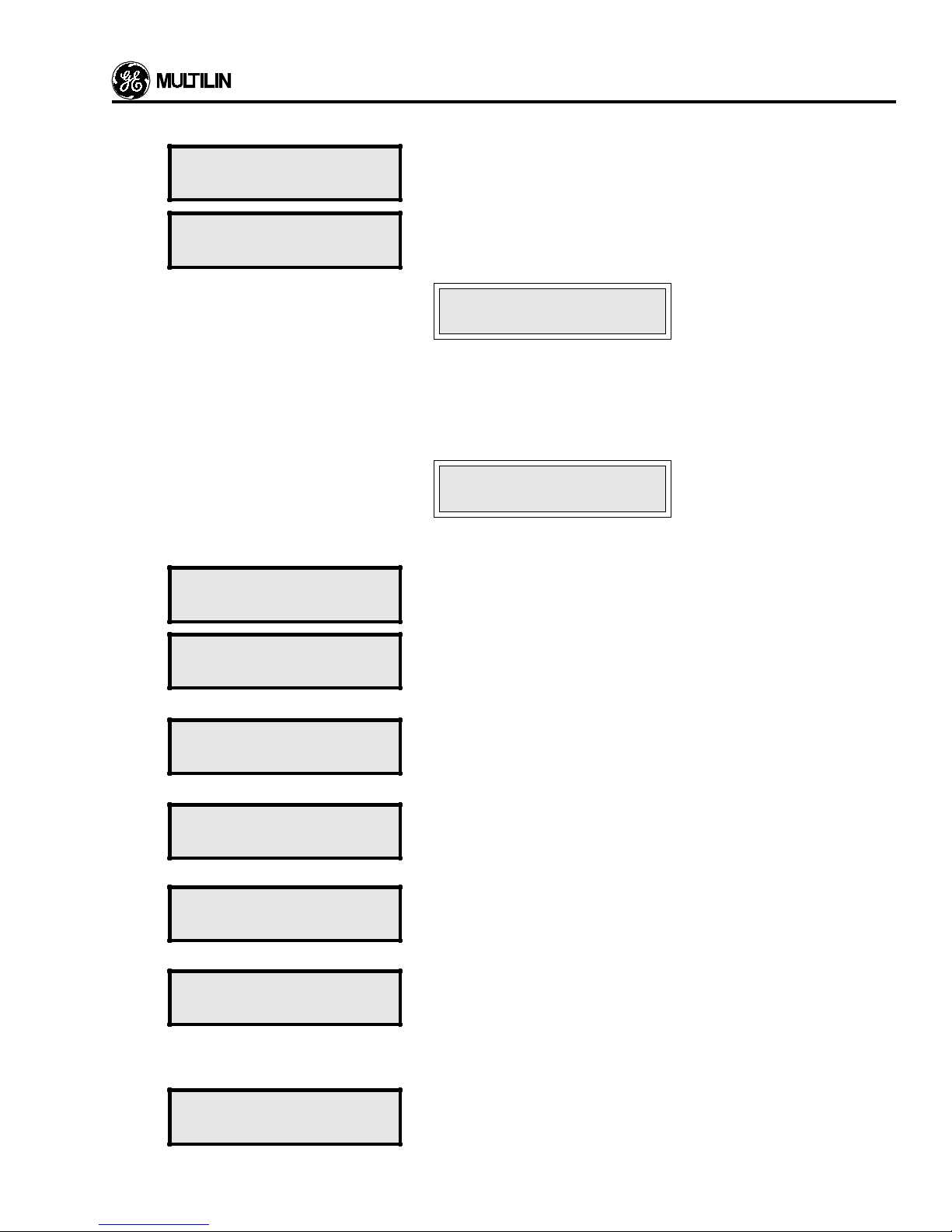
SETPOINTS MODE - A UT ORECLOSURE
Location Message Line Description
S 12.1
S 12.2
S 12.3
SETPOINTS
AUTO RECLOSURE
AUTO RECLOSURE
DISABLED
NO. OF RECLOSE
SHOTS 4
The setpoints page 12 header. All the setpoints required f or Auto Reclosure
are entered in this page.
This setpoint determines whether the reclosure scheme is enabled or
disabled when LOCAL mode is selected. When REMOTE mode is
selected this setpoint cannot be changed and the flash message
ILLEGAL STORE
IN REMOTE MODE
will be displayed.
The setpoints in messages S12.3 to S12.9 can only be stored while
autoreclosure is disabled. If an attempt is made to store a setpoint while
reclosure is enabled, the following message will flash:
NO STORE WHILE
RECLOSE ENABLE
Range: DISABLED/ENABLED.
This setpoint determines the number of reclose shots to implement.
Range: 0-4.
S 12.4
S 12.5
S 12.6
S 12.7
S 12.8
SHOT 1 DEAD TIME
2.0 SE C
SHOT 2 DEAD TIME
4.0 SE C
SHOT 3 DEAD TIME
6.0 SE C
SHOT 4 DEAD TIME
8.0 SE C
SCHEME RE SET
TIME 5 SEC
This setpoint determines the dead time after the first trip. The first
reclosure will be initiated after this time has elapsed.
Range: 0.3-300 sec.
This is part of 79R14 in the Autoreclosure Logic schematic.
Same as above for the second trip.
Range: 0.3-300 sec.
This is part of 79R14 in the Autoreclosure Logic schematic.
Same as above for the third trip.
Range: 0.3-300 sec.
This is part of 79R14 in the Autoreclosure Logic schematic.
Same as above for the fourth trip.
Range: 0.3-300 sec.
This is part of 79R14 in the Autoreclosure Logic schematic.
The time required for the reclosure TIME scheme to reset itself . This timer
will not operate unless the phase current in all phases is below the pickup
level.
Range: 1-255, increments of 1.
This is 79TR18, 79TR20, 79TR22, and 79TR24 in the Autoreclosure Logic
schematic.
S 12.9
RECLOSURE ENABLE
RELAY AUX2
This setpoint determines which relay will activate when reclosure is
enabled.
5-51
Page 96

SETPOINTS MODE - AUTORECLOSURE
Location Message Line Description
S 12.10
AUTO RECLOSURE
END OF PAGE
Last line of Setpoints, page 12, autoreclosure. Use the PAGE key to view
page 13.
5-52
Page 97
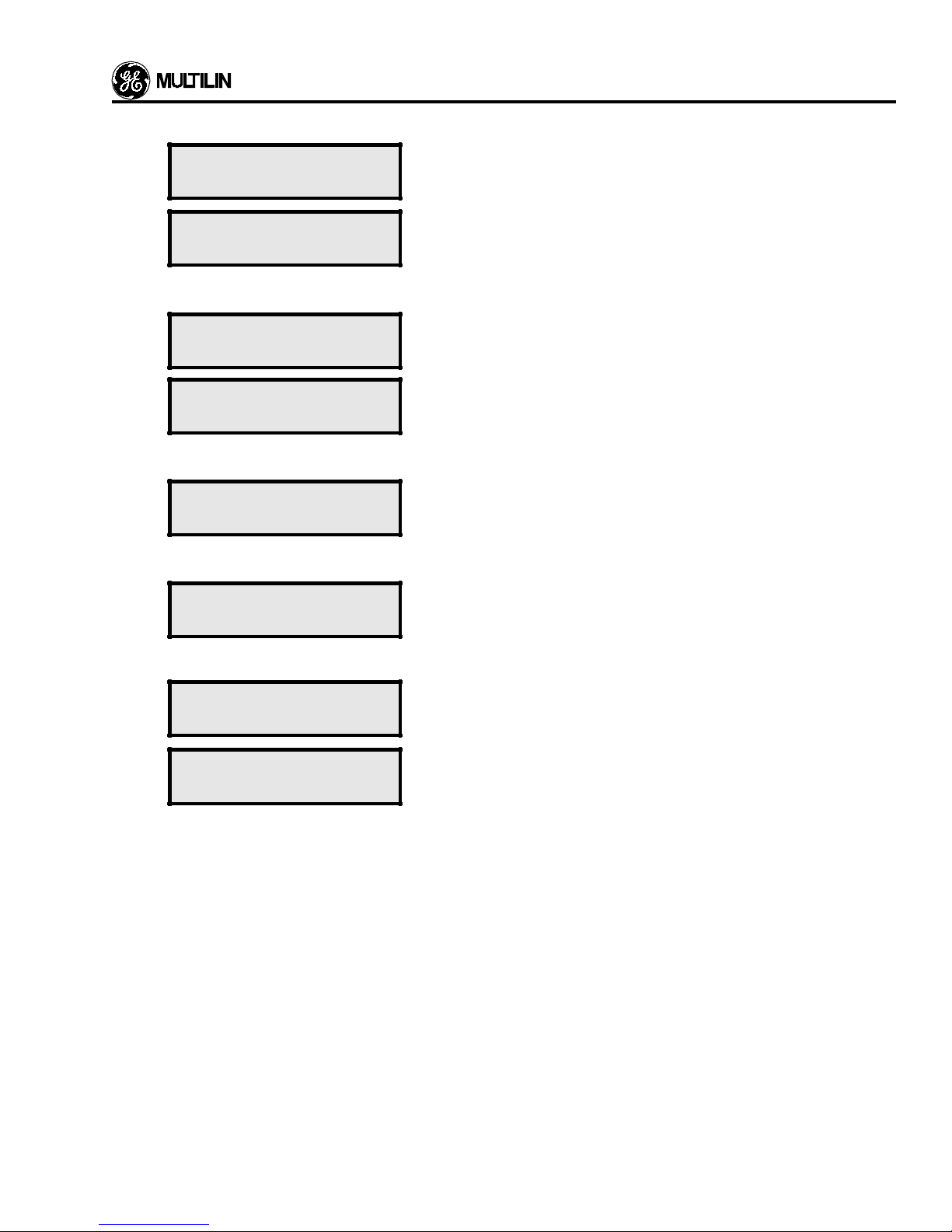
Location Message Line Description
SETPOINTS MODE - PHASE CUR VES
S 13.1
S 13.2
SETPOINTS
PHASE CU RVES
PHASE CURVE
The setpoints page 13 header. Setpoints required to program an alternate
phase curve are entered here.
This will enable the changing of the phase curve when enabled.
CHANGE DISABLED
Only message S 13.8 will appear if DISABLED is selected in message S 13.2.
S 13.3
SWITCH TO CURVE2
Enter which reclosure you wish to close onto using the alternative phase
curve. Alternative curves will remain until lockout occurs.
AFTER RECL. # 1
S 13.4
PH. O/C CURVE 2
Enter the curve shape for the alternative phase curve.
SHAPE EX TREM INV
Message S 13.5 will not appear if CUSTOM2 was selected in message S 13.4.
S 13.5
PHASE O/C
Enter the time dial for the alternative phase cur ve.
TIME DIAL 2 1
Messages S13.6 and S13.7 will only appear if CUSTOM2 was selected in message S13.4.
S 13.6
L
A
TRIP TIME2 (SEC)
1.03 xP/U= 1.0
The trip time for the first breakpoint of the prog rammable alternativ e phase
curve is entered here. The breakpoints are multiples of the pickup current.
The remainder of the messages in this section are identical to those found in the PHASE CURRENT page of setpoints.
S 13.7
L
A
S 13.8
TRIP TIME2 (SEC)
20.0 xP/U= 1.0
PHASE CURVES
The last trip time is entered here.
Last line of Setpoints, page 13. Use the PAGE key to view page 14.
END OF PAGE
5-53
Page 98
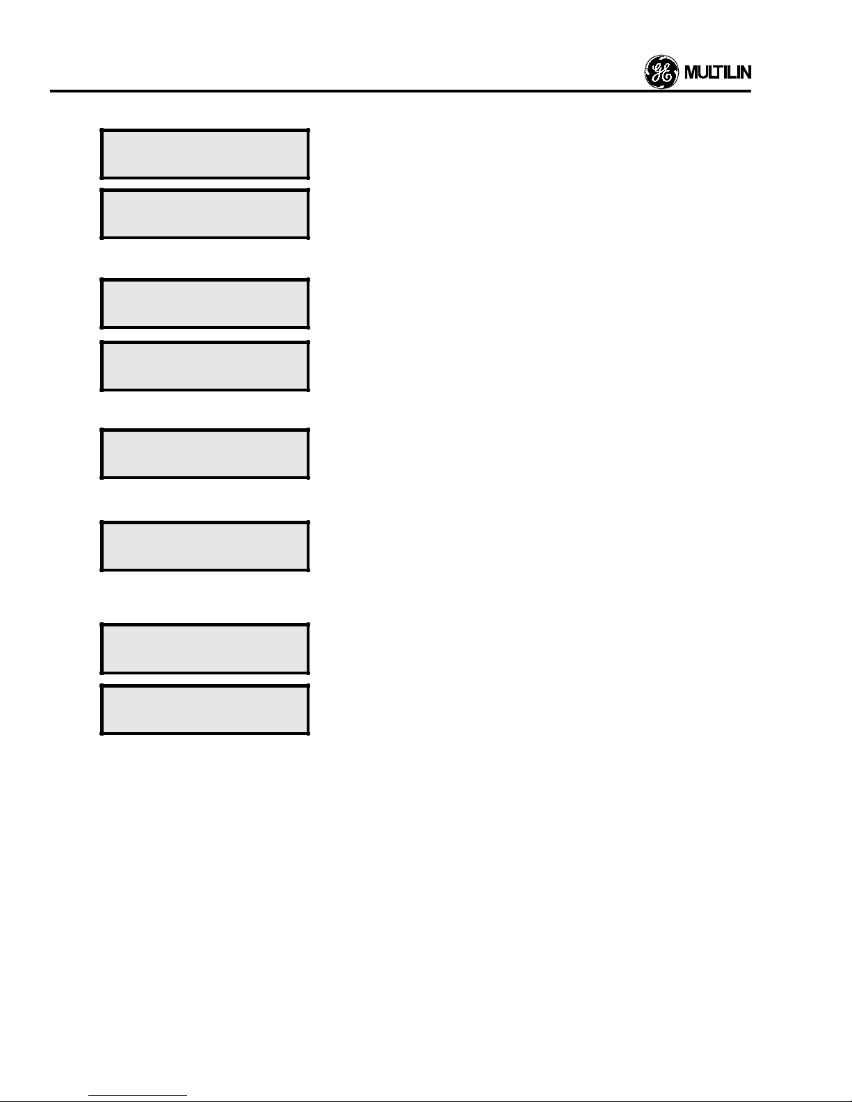
SETPOINTS MODE - GROUND CURVES
Location Message Line Description
S 14.1
SETPOINTS
The setpoints page 14 header. Setpoints required to program an alternate
ground curve are entered here.
GROUND CURVES
S 14.2
GROUND CU RVE
This will enable the changing of the ground curve.
CHANGE DISABLED
Only message S 14.8 will appear if DISABLED is selected in message S 14.2.
S 14.3
S 14.4
SWITCH TO CURVE2
AFTER RECL. # 1
Enter which reclosure you wish to close onto using the alternative ground
curve. Alternative curves will remain until lockout occurs.
Enter the curve shape for the alternative ground cur ve.
GND O/C CURVE 2
SHAPE EX TREM INV
Message S 14.5 will not appear if CUSTOM2 was selected in message S 14.4.
S 14.5
GROUND O/ C TIME
Enter the time dial for the alternative ground curve.
DIAL 2 1
Messages S14.6 and S14.7 will only appear if CUSTOM2 was selected in message S14.4.
S 14.6
L
A
TRIP TIME2 (SEC)
1.03 xP/U= 1.0
The trip time for the first breakpoint of the programmable alternative
ground curve is entered here. The breakpoints are multiples of the pickup
current.
The remainder of the messages in this section are identical to those found in the GROUND CURRENT page of setpoints.
S 14.7
L
A
S 14.8
TRIP TIME2 (SEC)
20.0 xP/U= 1.0
GROUND CU RVES
The last trip time is entered here.
Last line of Setpoints, page 14. This is the last page of Setpoints.
END OF PAGE
5-54
Page 99

FEA TURE INFORMATION
Event Recording Information
Event recording is a feature of the 565 feeder relays. Data
relating to one or more “events” is saved in memory and can
be viewed by the operator through the front panel display or
the rear RS232 printer port.
In order to use the Event Recording feature, the function
must be enabled. In Setpoint mode, the lines of the Configuration page allow users to enable the Event Recording and
Event Printing features.
(1.0) “Event” Definition
An “event” is defined as:
a) occurance of any set trip conditions,
b) occurance or disappearance of any set alarm condi-
tion, or
c) occurance of other extraordinary event (eg. install/
removal of access jumper, enable/disable curve adjustment ...etc).
(1.1) Trip Event
Currently available trip events:
a) any of the 4 timed overcurrent trips,
b) any of the 4 instantaneous overcurrent trips,
c)overvoltage or under voltage trip,
d) analog input trip,
e) any of 4 external trips ,
f) power factor, and frequency trip (with Option Card).
b) enable/disable of block instantaneous trip,
c)enable/disable of block non-instantaneous trip,
d) enable/disable of overcurrent curve adjustment,
e) illegal access to setpoint,
f) disappearance of alarm conditions,
g) system manual reset,
h) local/remote mode switch.
(2.0) Event Storage
All events will be stored in a memory buffer of the 565
unit, and up to 40 events will accumulated. The buffer is
operated in First-In-First-Out (FIFO) mode. If the buff er is full
with 40 stored events, then as each new event occurs the
oldest will be lost.
(2.1) Event Format
Each event is characterized by cause, time and date,
and the magnitude of several measured feeder parameters,
which are pertinent to the event, at the time of occurance.
The parameters which will be saved are:
a) the cause of the event;
b) the time and date of the event;
c) each of the 4 RMS currents if it was a tr ip or alarm
event, with the exception of Analog Input Trip, Analog
Input Alarm and Accumulated KA2 Alarm events;
and
d)each of the 3 RMS phase (or line) v oltages if it was a
trip or an alarm event, with the exception of Analog
Input Trip, Analog Input Alarm and Accumulated KA2
Alarm.
(3.0) Event Display Format
(1.2) Alar m Event
Currently available alarm events:
a) any of the 2 overcurrent alarms,
b) overvoltage alarm,
c) undervoltage alarm,
d) analog input alarm,
e) accumulated KA2 alarm,
f) definite time alarms (or switch alarms),
g) amps demand metering
h) kW, and kVAR demand alarms (with Option Card),
i) power factor and frequency alarms (with Option Card),
j) breaker discrepancy and trip coil supervision alarms
(with Option Card),
k) MTM communications alar m (with Option Card).
(1.3) “Others” Event
Currently available “others” events:
a) installation/removal of the access jumper,
To view all the recorded events, users must enter the
Actual Value mode, and select the “Event” page.
6-1
Page 100

FEA TURE INFORMATION
Cause of Event Displayed Message
1) Phase A Timed O/C Trip PH-A TIME O/C T
2) Phase B Timed O/C Trip PH-B TIME O/C T
3) Phase C Timed O/C Trip PH-C TIME O/C T
4) Ground Timed O/C Trip GND TIMED O/C T
5) Phase A Inst Trip PH-A INST O/C T
6) Phase B Inst Trip PH-B INST O/C T
7) Phase C Inst Trip PH-C INST O/C T
8) Ground Inst Trip GND INST O/C T
9) Over voltage Trip OVERVOLTAGE T
10) Undervoltage Trip UNDERVOLTAGE T
11) Analog Input Trip ANALOG INPUT T
12) External Tr ip #1 EXT. TRIP #1 T
13) External Tr ip #2 EXT. TRIP #2 T
14) External Tr ip #3 EXT. TRIP #3 T
15) External Tr ip #4 EXT. TRIP #4 T
16) Power Factor Trip P/F TRIP T
17) Frequency Tr ip FREQ. TRIP T
18) Phase O/C Alarm PH O/C ALARM A
19) Ground O/C Alarm GND O/C ALARM A
20) Overvoltage Alarm OVERVOLTAGE A
21) Undervoltage Alarm UNDERVOLTAGE A
22) Analog Input Alarm ANALOG INPUT A
23) Accumulated KA2 Alarm ACCUM KA A
24) Definite Time Alarm 1 SWITCH ALARM1 A
25) Definite Time Alarm 2 SWITCH ALARM2 A
26) Amps Demand Alarm AMPS DEMAND A
27) KW Demand Alarm KW DEMAND A
28) KVAR Demand Alarm KVAR DEMAND A
29) Power Factor Alarm P/F ALARM A
30) Frequency Alarm FREQ. ALARM A
31) Breaker Discepancy Alar m BRK DISCRPNCY A
32) Trip Coil Alarm TRIP COIL A
33) MTM Communications Alarm MTM COMM ALM A
34) Phase O/C Alarm Reset PH OC ALM RST O
35) Ground O/C Alarm Reset GD OC ALM RST O
36) Overvoltage Alarm Reset OV ALARM RST O
37) Undervoltage Alarm Reset UV ALARM RST O
38) Analog Input Alarm Reset AI ALARM RST O
39) Definite Time Alarm1 Reset SW ALM1 RST O
40) Definite Time Alarm2 Reset SW ALM2 RST O
41) Breaker Discrepancy Alar m Reset BRK ALM RST O
42) Access Jumper Installed AC JUMPER INS O
43) Access Jumper Removed AC JUMPER REM O
44) Block Inst Trip Enabled INST-BLOCK EN O
45) Block Inst Trip Disabled INST-BLOCK DI O
46) Block Timed O/C Trips Enabled TIMED-BLK ENB O
47) Block Timed O/C Trips Disabled TIMED-BLK DIS O
48) Curve Adjust Enabled CURVE ADJ. EN O
49) Curve Adjust Disabled CURVE ADJ. DI O
50) Illegal Setpoint Access ILL-ACCESS O
51) System Manual Reset MANUAL RESET O
52) Control Switch to Remote SWITCH REMOTE O
53) Control Switch to Local SWITCH LOCAL O
6-2
 Loading...