

Page 1
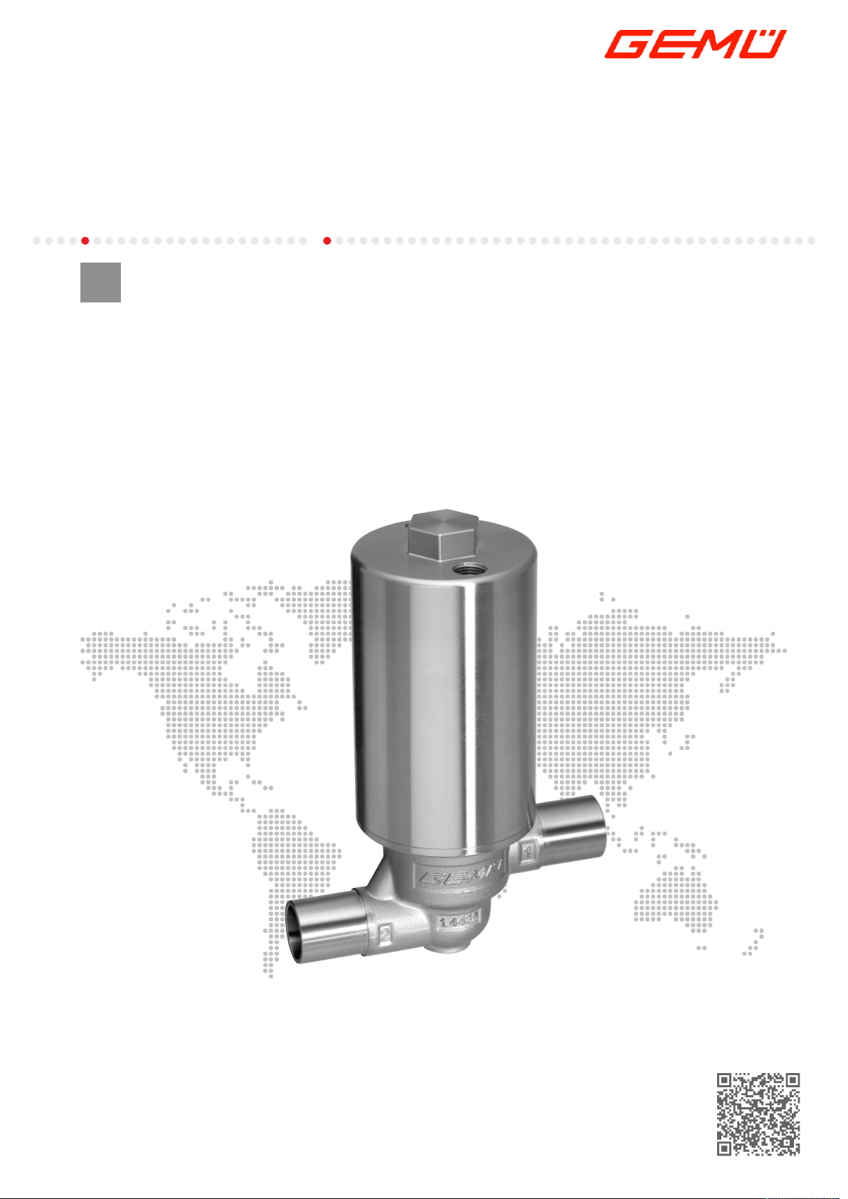
GEMÜ F40
Pneumatically operated filling valve
EN
Operating instructions
further information
webcode: GW-F40
Page 2

All rights including copyrights or industrial property rights are expressly reserved.
Keep the document for future reference.
© GEMÜ Gebr. Müller Apparatebau GmbH & Co. KG
07.11.2019
www.gemu-group.com2 / 24GEMÜ F40
Page 3

Contents
1 General information .................................................. 4
1.1 Information ......................................................... 4
1.2 Symbols used ..................................................... 4
1.3 Definition of terms ............................................. 4
1.4 Warning notes .................................................... 4
2 Safety information .................................................... 5
3 Product description ................................................... 5
4 Correct use ............................................................... 6
5 Order data ................................................................. 7
6 Technical data .......................................................... 8
7 Dimensions ............................................................... 11
8 Manufacturer's information ....................................... 14
8.1 Delivery ............................................................... 14
8.2 Packaging ........................................................... 14
8.3 Transport ............................................................ 14
8.4 Storage ............................................................... 14
9 Installation in piping .................................................. 14
9.1 Preparing for installation ................................... 14
9.2 Installation with butt weld spigots .................... 15
9.3 Installation with clamp connections ................. 15
10 Commissioning ......................................................... 15
11 Error clearance .......................................................... 16
12 Inspection/servicing .................................................. 17
13 Removal from piping ................................................. 20
14 Disposal .................................................................... 20
15 Returns ..................................................................... 20
16 Declaration of Incorporation according to 2006/42/
EC (Machinery Directive) ........................................... 21
3 / 24
GEMÜ F40www.gemu-group.com
Page 4
1 General information
SIGNAL WORD
Type and source of the danger
Possible
symbol for the
specific
danger
Possible consequences of non-observance.
Measures for avoiding danger.
1 General information
1.1 Information
– The descriptions and instructions apply to the stand-
ard versions. For special versions not described in this
document the basic information contained herein applies in combination with any additional special documentation.
– Correct installation, operation, maintenance and repair
work ensure faultless operation of the product.
– Should there be any doubts or misunderstandings, the
German version is the authoritative document.
– Contact us at the address on the last page for staff
training information.
1.2 Symbols used
The following symbols are used in this document:
Symbol Meaning
Tasks to be performed
Response(s) to tasks
– Lists
1.3 Definition of terms
Working medium
The medium that flows through the GEMÜ product.
Control medium
The medium whose increasing or decreasing pressure
causes the GEMÜ product to be actuated and operated.
Control function
The possible actuation functions of the GEMÜ product.
PD
PD = Plug Diaphragm
1.4 Warning notes
Wherever possible, warning notes are organised according to
the following scheme:
Warning notes are always marked with a signal word and
sometimes also with a symbol for the specific danger.
The following signal words and danger levels are used:
DANGER
Imminent danger!
▶ Non-observance can cause death or
severe injury.
WARNING
Potentially dangerous situation!
▶ Non-observance can cause death or
severe injury.
CAUTION
Potentially dangerous situation!
▶ Non-observance can cause moderate
to light injury.
NOTICE
Potentially dangerous situation!
▶ Non-observance can cause damage to
property.
The following symbols for the specific dangers can be used
within a warning note:
Symbol Meaning
Danger of explosion
Corrosive chemicals
Hot plant components!
www.gemu-group.com4 / 24GEMÜ F40
Page 5
1
2
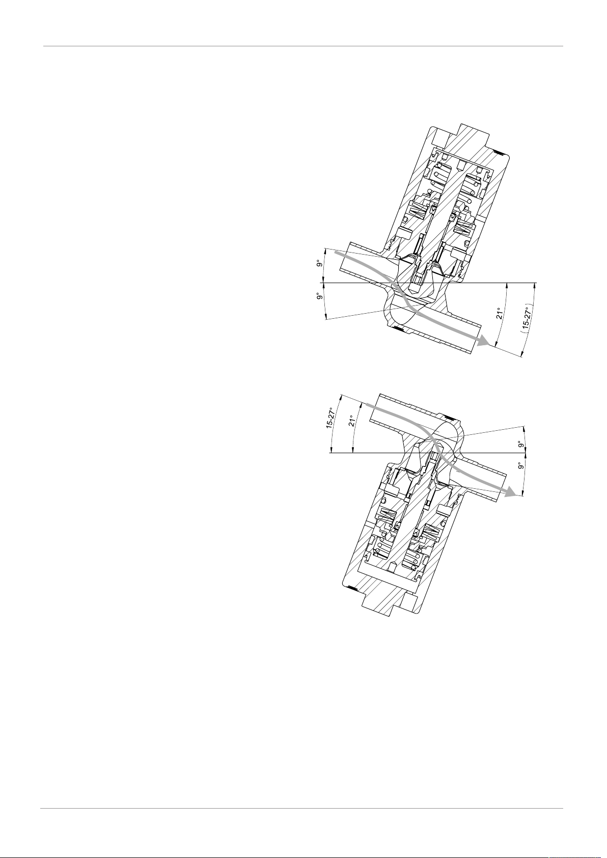
1 → 2, optimal draining and filling properties
over the seat
1
2
under the seat
2 -> 1, better pressure stability and higher flow
3 Product description
2 Safety information
The safety information in this document refers only to an individual product. Potentially dangerous conditions can arise
in combination with other plant components, which need to
be considered on the basis of a risk analysis. The operator is
responsible for the production of the risk analysis and for
compliance with the resulting precautionary measures and
regional safety regulations.
The document contains fundamental safety information that
must be observed during commissioning, operation and
maintenance. Non-compliance with these instructions may
cause:
– Personal hazard due to electrical, mechanical and
chemical effects.
– Hazard to nearby equipment.
– Failure of important functions.
– Hazard to the environment due to the leakage of dan-
gerous materials.
The safety information does not take into account:
– Unexpected incidents and events, which may occur
during installation, operation and maintenance.
– Local safety regulations which must be adhered to by
the operator and by any additional installation person-
nel.
3 Product description
3.1 Construction
3.1.1 Flow direction
Prior to commissioning:
1. Transport and store the product correctly.
2. Do not paint the bolts and plastic parts of the product.
3. Carry out installation and commissioning using trained
4. Provide adequate training for installation and operating
5. Ensure that the contents of the document have been fully
6. Define the areas of responsibility.
7. Observe the safety data sheets.
8. Observe the safety regulations for the media used.
During operation:
9. Keep this document available at the place of use.
10. Observe the safety information.
11. Operate the product in accordance with this document.
12. Operate the product in accordance with the specifica-
13. Maintain the product correctly.
14. Do not carry out any maintenance work and repairs not
personnel.
personnel.
understood by the responsible personnel.
tions.
described in this document without consulting the manufacturer first.
In cases of uncertainty:
15. Consult the nearest GEMÜ sales office.
www.gemu-group.com 5 / 24 GEMÜ F40
Page 6
4 Correct use
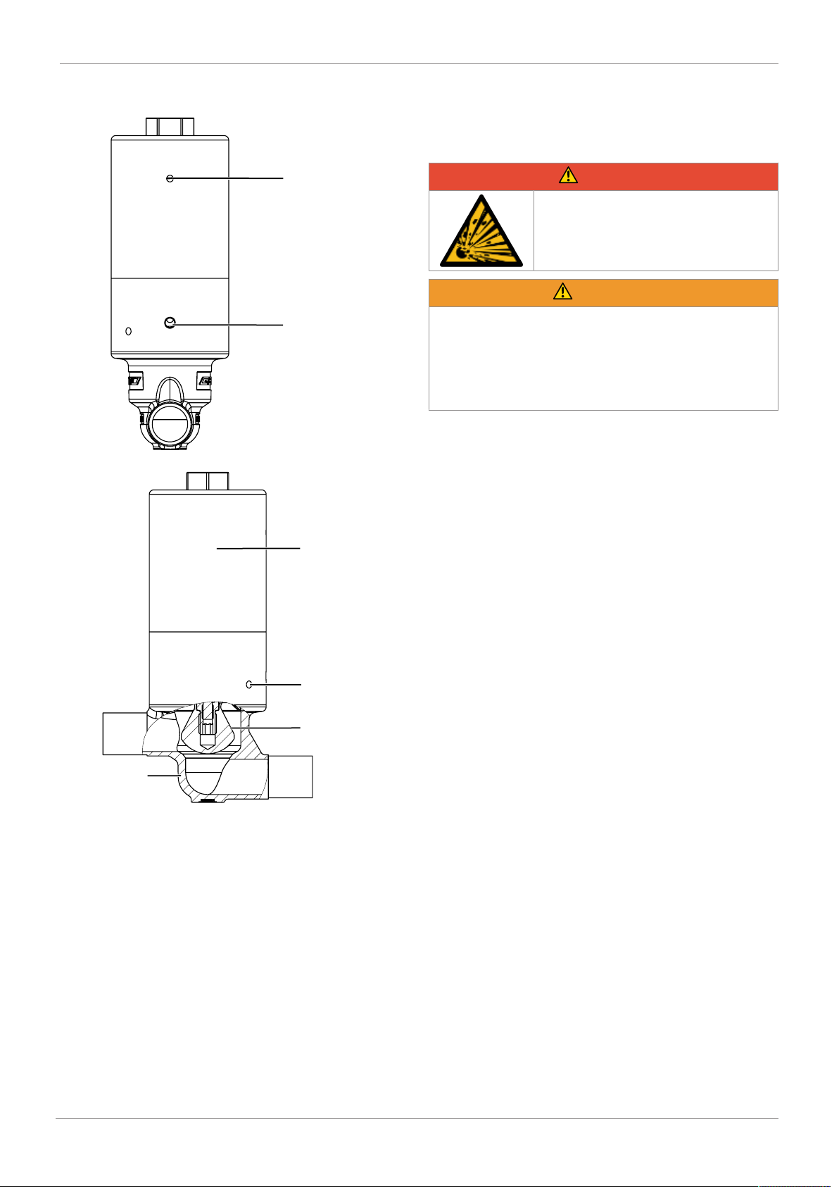
Vent hole
Leak detection hole
Actuator
Opening protection
PTFE diaphragm
(PD)
Stainless steel
body
3.1.2 PD seal system
The filling valve can be opened or closed via 2 control functions (Normally open and Normally closed).
4 Correct use
DANGER
Danger of explosion
▶ Risk of death or severe injury.
● Do not use the product in potentially
explosive zones.
WARNING
Improper use of the product!
▶ Risk of severe injury or death.
▶ Manufacturer liability and guarantee will be void.
● Only use the product in accordance with the operating
conditions specified in the contract documentation and
this document.
The product is designed for installation in piping systems
and for controlling a working medium.
The product is not intended for use in potentially explosive
areas.
● Use the product in accordance with the technical data.
3.2 Description
The GEMÜ F40 2/2-way filling valve is designed for filling
processes in aseptic and hygienic areas of application. Flow
rates up to 6,600 l/h are possible depending on the version.
The sealing concept of the valve is based on the GEMÜ PD
design, whereby the actuator is hermetically separated from
the medium. All actuator parts (except the seals) are made
from stainless steel. Normally Closed and Normally Open
control functions are available.
3.3 Function
The product is a pneumatically operated 2/2-way filling valve
in stainless steel. The GEMÜ F40 2/2-way filling valve is designed for installation in piping systems.
www.gemu-group.com6 / 24GEMÜ F40
Page 7
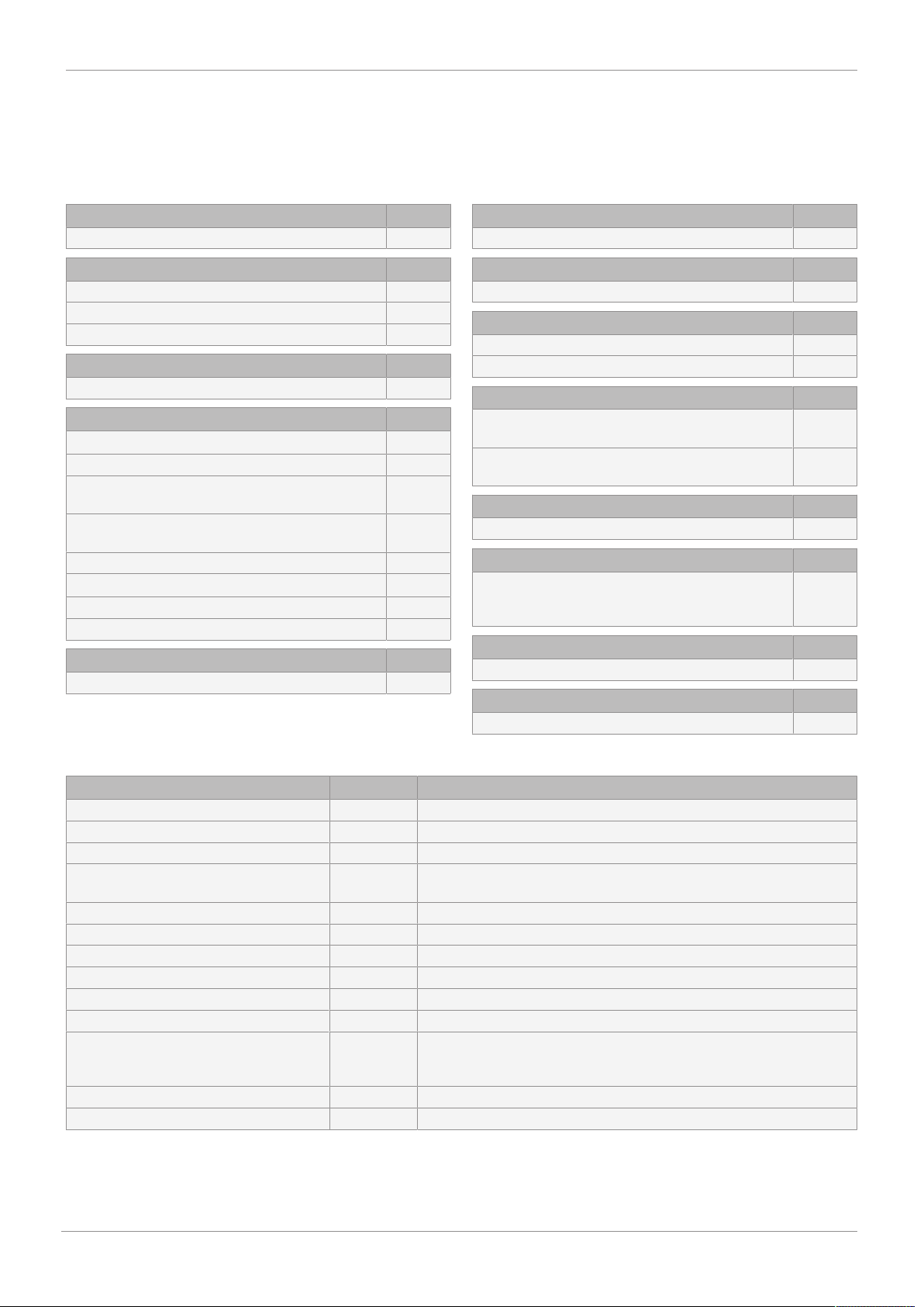
5 Order data
The order data provide an overview of standard configurations.
Please check the availability before ordering. Other configurations available on request.
Order codes
5 Order data
1 Type Code
Stainless steel PD valve, pneumatic F40
2 DN Code
DN 10 10
DN 15 15
DN 20 20
3 Body configuration Code
2/2-way body D
4 Connection type Code
Spigot
Spigot DIN 0
Spigot EN 10357 series B,
formerly DIN 11850 series 1
Spigot EN 10357 series A (formerly DIN 11850
series 2) / DIN 11866 series A
Spigot ASME BPE / DIN 11866 series C 59
Clamp
Clamp DIN 32676 series A 86
Clamp ASME BPE 88
5 Valve body material Code
1.4435, investment casting C3
16
17
6 Seal material Code
PTFE 5
7 Valve body adaptor Code
Adaptor for PD size 3 3
8 Control function Code
Normally closed (NC) 1
Normally open (NO) 2
9 Actuator version Code
Actuator without accessories, with standard
spring set
Actuator with M12x1 thread for accessories with
standard spring set
10 Bypass Code
On request
11 Surface Code
Ra ≤ 0.8 µm (30 µin.) for media wetted surfaces,
in accordance with DIN 11866 H3,
mechanically polished internal
12 Seat diameter Code
20 mm H
13 Special version Code
Special version for 3A M
0N
1N
1502
Order example
Order option Code Description
1 Type F40 Stainless steel PD valve, pneumatic
2 DN 15 DN 15
3 Body configuration D 2/2-way body
4 Connection type 17 Spigot EN 10357 series A (formerly DIN 11850 series 2) / DIN 11866
series A
5 Valve body material C3 1.4435, investment casting
6 Seal material 5 PTFE
7 Valve body adaptor 3 Adaptor for PD size 3
8 Control function 1 Normally closed (NC)
9 Actuator version 0N Actuator without accessories, with standard spring set
10 Bypass On request
11 Surface 1502 Ra ≤ 0.8 µm (30 µin.) for media wetted surfaces,
in accordance with DIN 11866 H3,
mechanically polished internal
12 Seat diameter H 20 mm
13 Special version M Special version for 3A
www.gemu-group.com
7 / 24
GEMÜ F40
Page 8
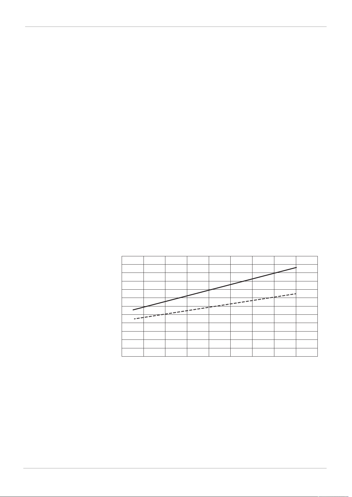
0123456789
6
5.5
5
4.5
4
3.5
3
2.5
2
1.5
1
0.5
0
Control pressure [bar]
Operating pressure [bar]
Flow direction
under the seat
Flow direction
over the seat
6 Technical data
6 Technical data
6.1 Medium
Working medium:
Corrosive, inert, gaseous and liquid media which have no negative impact on the physical and
chemical properties of the body and diaphragm material.
Control medium:
6.2 Temperature
Media temperature:
Sterilisation temperature:
Control medium
temperature:
Ambient temperature:
Storage temperature:
6.3 Pressure
Operating pressure:
Control pressure:
Inert gases
-10 to 140 °C
Hot water max. 4 bar at 140 °C, max. 60 min
Steam max. 2 bar at 140 °C, max. 60 min
max. 60 °C
-10 to 60 °C
0 to 40 °C
C.f. 1 over the seat max. 7 bar (1 → 2)
C.f. 1 under the seat max. 6 bar (2 → 1)
C.f.2 max. 7 bar
C.f. 1 6 to 7 bar
C.f.2 max. 6 bar
Control pressure – Operating pressure characteristic
Filling volume:
C.f. 1 0.017 dm³
C.f.2 0.010 dm³
GEMÜ F40
8 / 24
www.gemu-group.com
Page 9
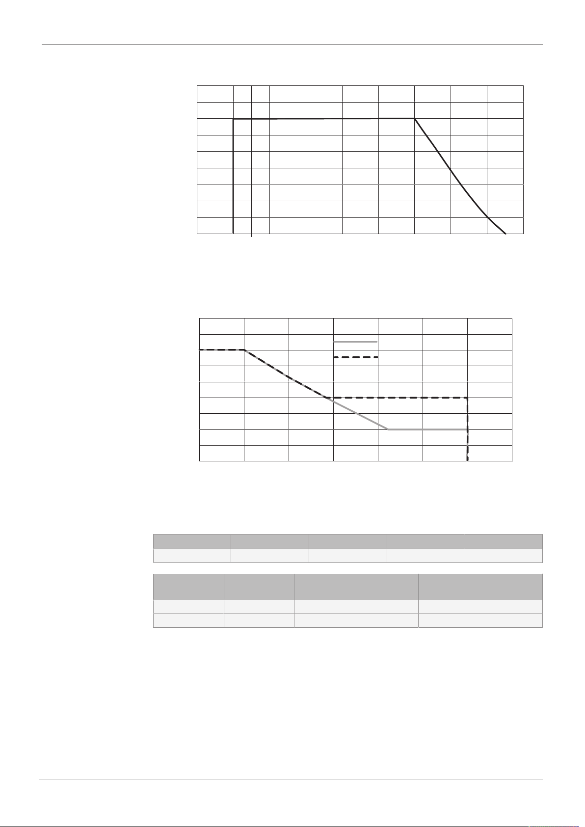
-30 -10 10 30 50 70 90 110 130 150
9
8
7
6
5
4
3
2
1
0
0
Pressure [bar]
Temperature [°C]
9
8
7
6
5
4
3
2
1
0
80 90 100 110 120 130 140 150
Temperature [°C]
Pressure [bar]
Hot water
Steam
6 Technical data
Pressure/temperature
correlation:
Process:
Hot water, steam
Hot water max. 4 bar at 140 °C, max. 60 min
Steam max. 2 bar at 140 °C, max. 60 min
Leakage rate:
Kv values:
6.4 Product compliance
Machinery Directive:
Food:
Seat seal Standard Test procedure Leakage rate Test medium
EPDM, FPM, PTFE DIN EN 12266-1 P12 A Air
DN Code Flow direction
over the seat [1 → 2]
10 17 2.7 m³/h 2.8 m³/h
15 17 6.1 m³/h 6.6 m³/h
Kv values in m³/h
2006/42/EU
FDA
USP Class VI
Regulation (EC) No. 1935/2004
Regulation (EC) No. 10/2011
EHEDG certified
9 / 24
Flow direction
under the seat [2 → 1]
GEMÜ F40www.gemu-group.com
Page 10

6 Technical data
6.5 Mechanical data
Cycle duties:
Weight: Actuator
Cycle duties (over 10 million)
The cycle duties depend on the operating parameters. High pressures and media temperatures
can lead to a shorter service life.
Control function 1 1.24 kg
Control function 2 1.10 kg
Body
Spigot 0.30 kg
Clamp 0.22 kg
GEMÜ F40
10 / 24
www.gemu-group.com
Page 11
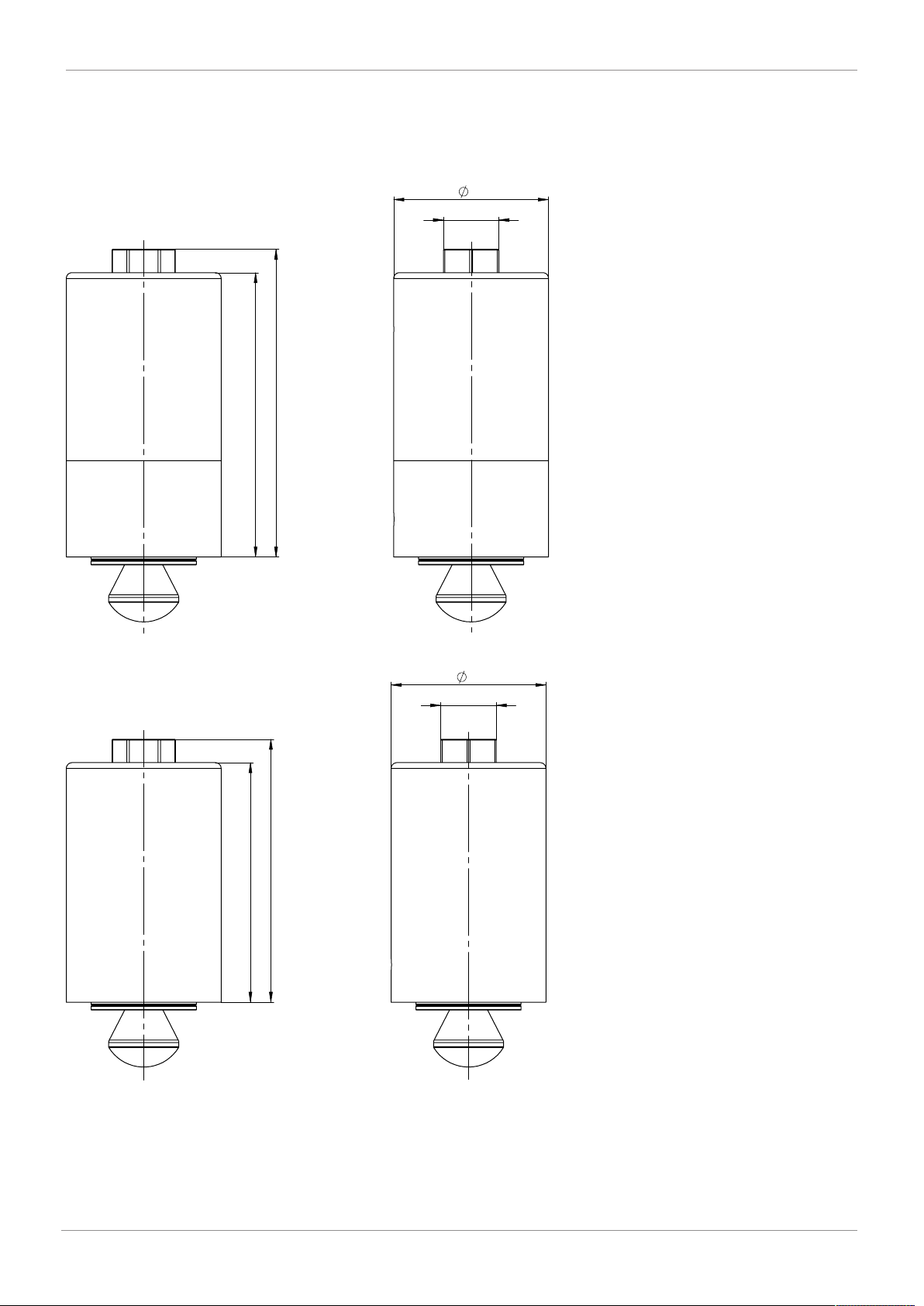
7 Dimensions
53
97,35
105,35
SW 19
53
82
90
SW 19
7.1 Actuator dimensions
7.1.1 Control function 1
7 Dimensions
7.1.2 Control function 2
11 / 24
GEMÜ F40www.gemu-group.com
Page 12
L
H1
s
c
H3
H2
B
d
7 Dimensions
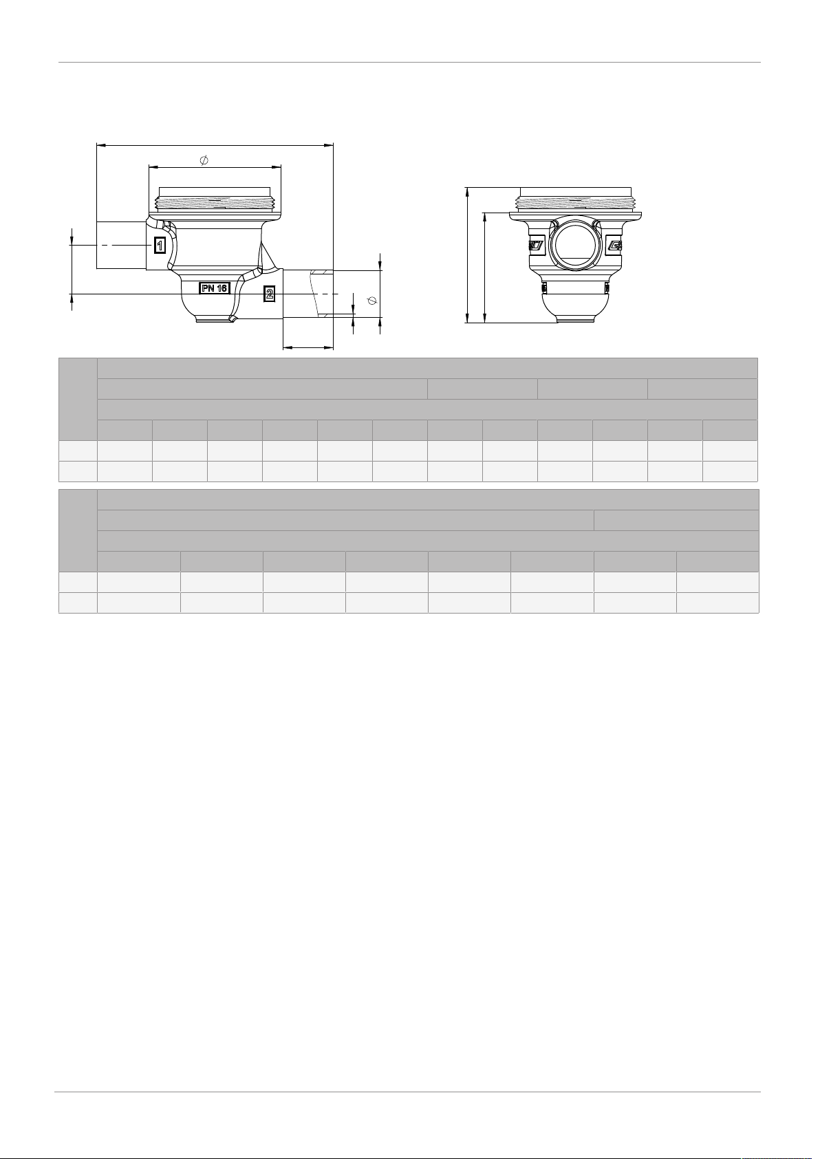
7.2 Body dimensions
7.2.1 Spigot
DN Connection types code
Material code C3
L ØB c H1 H2 H3 ød s ød s ød s
95.0 53.0 20.0 21.5 41.2 51.2 - - - - 13.0 1.5
10
95.0 53.0 20.0 19.5 44.2 54.2 18.0 1.5 18.0 1.0 19.0 1.5
15
DN Connection types code
Material code C3
L ØB c H1 H2 H3 ød s
15
20
Dimensions in mm
1)
Connection type
Code 0: Spigot DIN
Code 16: Spigot EN 10357 series B, formerly DIN 11850 series 1
Code 17: Spigot EN 10357 series A (formerly DIN 11850 series 2) / DIN 11866 series A
Code 59: Spigot ASME BPE / DIN 11866 series C
2)
Valve body material
Code C3: 1.4435, investment casting
95.0 53.0 20.0 21.5 41.2 51.2 12.70 1.65
95.0 53.0 20.0 19.5 44.2 54.2 19.05 1.65
1)
0 16 17
2)
1)
59
2)
GEMÜ F40
12 / 24
www.gemu-group.com
Page 13
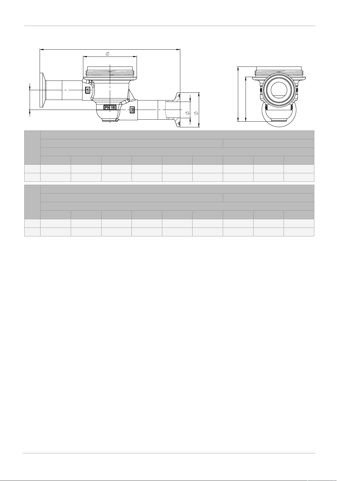
7.2.2 Clamp
H1
B
L
d1
d3
H2
H3
7 Dimensions
DN Connection types code
Material code C3
L ØB c H1 H2 H3 Ød1 Ød3 s
10
15
121.0 53.0 20.0 21.5 41.2 51.2 10.0 34.0 1.5
121.0 53.0 20.0 19.5 44.2 54.2 16.0 34.0 1.5
DN Connection types code
Material code C3
L ØB c H1 H2 H3 Ød1 Ød3 s
15
20
Dimensions in mm
1)
2)
121.0 53.0 20.0 21.5 41.2 51.2 9.40 25.0 1.65
121.0 53.0 20.0 19.5 44.2 54.2 15.75 25.0 1.65
Connection type
Code 86: Clamp DIN 32676 series A
Code 88: Clamp ASME BPE
Valve body material
Code C3: 1.4435, investment casting
1)
86
2)
1)
88
2)
13 / 24
GEMÜ F40www.gemu-group.com
Page 14
8 Manufacturer's information
8 Manufacturer's information
8.1 Delivery
● Check that all parts are present and check for any dam-
age immediately upon receipt.
The product's performance is tested at the factory. The
scope of delivery is apparent from the dispatch documents
and the design from the order number.
8.2 Packaging
The product is packed in a cardboard box which can be recycled as paper.
8.3 Transport
1. Only transport the product by suitable means. Do not
drop. Handle carefully.
2. After the installation dispose of transport packing material according to relevant local or national disposal regulations / environmental protection laws.
8.4 Storage
1. Store the product free from dust and moisture in its original packaging.
2. Avoid UV rays and direct sunlight.
3. Do not exceed the maximum storage temperature (see
chapter "Technical data").
4. Do not store solvents, chemicals, acids, fuels or similar
fluids in the same room as GEMÜ products and their
spare parts.
9 Installation in piping
9.1 Preparing for installation
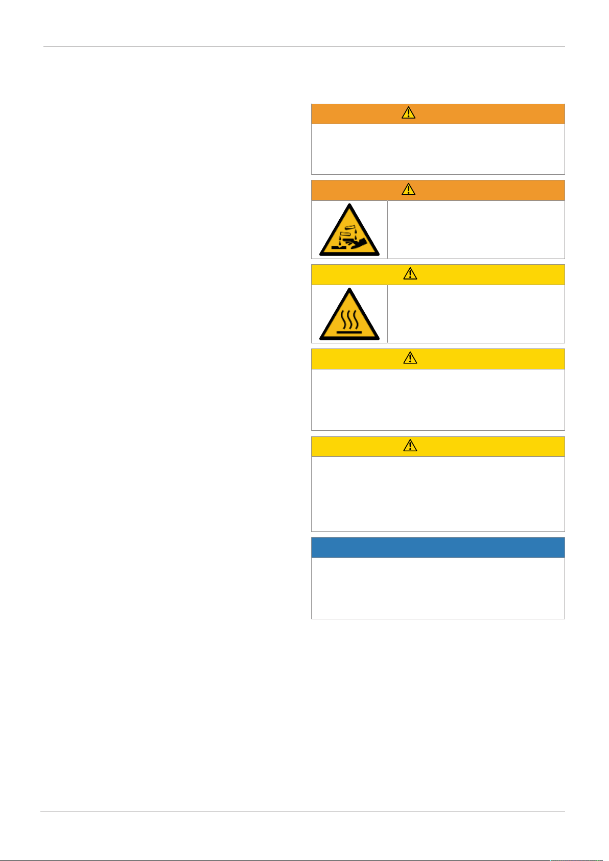
WARNING
The equipment is subject to pressure!
▶ Risk of severe injury or death.
● Depressurize the plant.
● Completely drain the plant.
WARNING
Corrosive chemicals
▶ Risk of caustic burns
● Wear suitable protective gear.
● Completely drain the plant.
CAUTION
Hot plant components!
▶ Risk of burns!
● Only work on plant that has cooled
down.
CAUTION
Exceeding the maximum permissible pressure.
▶ Damage to the GEMÜ product.
● Provide precautionary measures against exceeding the
maximum permitted pressures caused by pressure
surges (water hammer).
CAUTION
Use as step.
▶ Damage to the product.
▶ Risk of slipping-off.
● Choose the installation location so that the product can-
not be used as a foothold.
● Do not use the product as a step or a foothold.
NOTICE
Suitability of the product!
▶ The product must be appropriate for the piping system
operating conditions (medium, medium concentration,
temperature and pressure) and the prevailing ambient
conditions.
www.gemu-group.com14 / 24GEMÜ F40
Page 15
10 Commissioning
NOTICE
Tools
▶ The tools required for installation and assembly are not
included in the scope of delivery.
● Use appropriate, functional and safe tools.
1. Ensure the product is suitable for the relevant application.
2. Check the technical data of the product and the materials.
3. Keep appropriate tools ready.
4. Wear appropriate protective gear, as specified in the plant
operator's guidelines.
5. Observe appropriate regulations for connections.
6. Have installation work carried out by trained personnel.
7. Shut off the plant or plant component.
8. Secure the plant or plant component against recommissioning.
9. Depressurize the plant or plant component.
10. Completely drain the plant (or plant component) and let it
cool down until the temperature is below the media vaporization temperature and cannot cause scalding.
11. Correctly decontaminate, rinse and ventilate the plant or
plant component.
12. Lay piping so that the product is protected against transverse and bending forces, and also from vibrations and
tension.
13. Protect the piping against the total weight of the valve, vibrations during operation, as well as torques generated
during assembly and disassembly.
14. Only install the product between matching aligned pipes
(see chapters below).
15. Please note the flow direction (see chapter "Flow direction").
16. Please note the installation position (see chapter "Installation position").
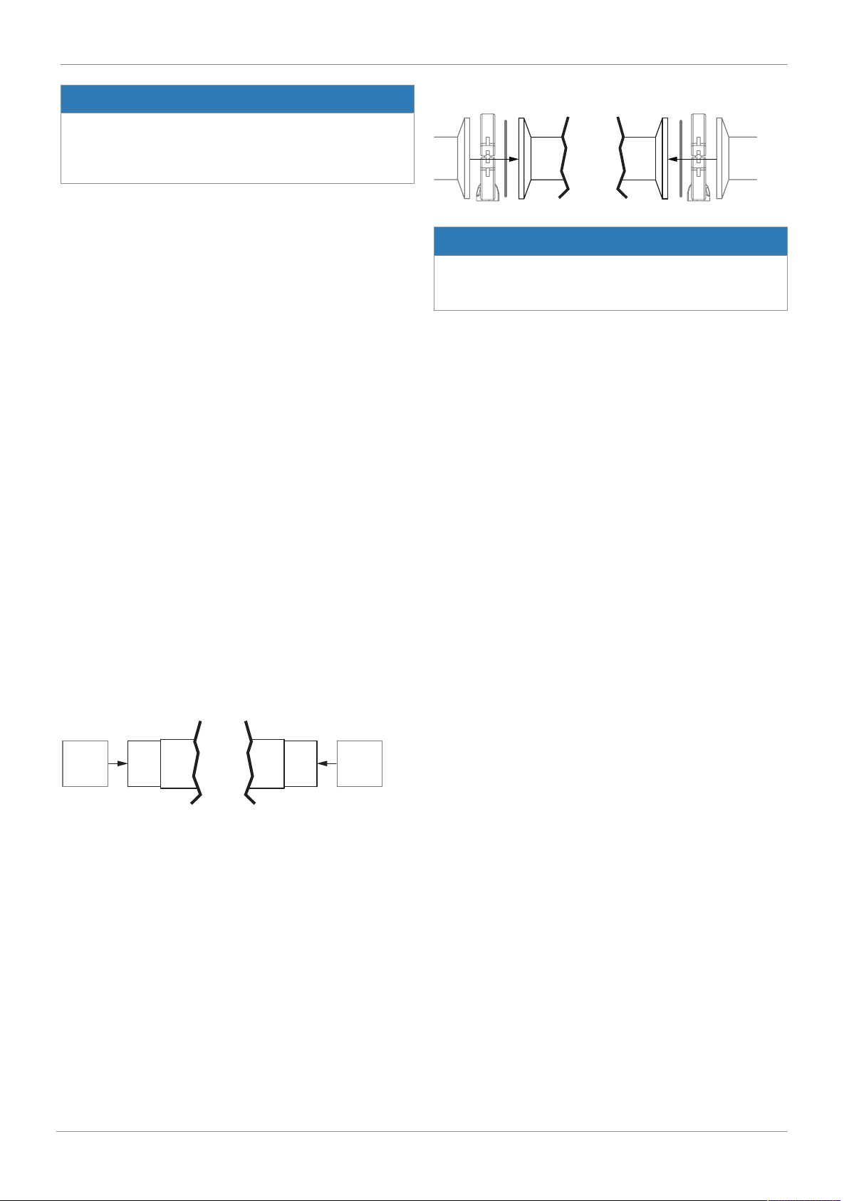
9.3 Installation with clamp connections
Fig.2: Clamp connection
NOTICE
Gasket and clamp
▶ The gasket and clamps for clamp connections are not in-
cluded in the scope of delivery.
1. Keep ready gasket and clamp.
2. Carry out preparation for installation (see chapter "Preparing for installation").
3. Insert the corresponding gasket between the body of the
product and the pipe connection.
4. Connect the gasket between the body of the product and
the pipe connection using clamps.
5. Re-attach or reactivate all safety and protective devices.
10 Commissioning
ü The product is installed in piping.
ü The product is pneumatically connected.
1. Check the tightness and the function of the product
(close and reopen the product).
2. Flush the piping system of new plant and following repair
work (the product must be fully open).
ð Harmful foreign matter has been removed.
ð The product is ready for use.
3. Commission the product.
9.2 Installation with butt weld spigots
Fig.1: Butt weld spigots
1. Carry out preparation for installation (see chapter "Preparing for installation").
2. Remove the actuator before welding the valve into the
plant (see chapter "Removing the actuator").
3. Adhere to good welding practices!
4. Weld the body of the product in the piping.
5. Allow butt weld spigots to cool down.
6. Mount the actuator on the valve body (see chapter
"Mounting the actuator").
7. Re-attach or reactivate all safety and protective devices.
8. Flush the system.
www.gemu-group.com 15 / 24 GEMÜ F40
Page 16
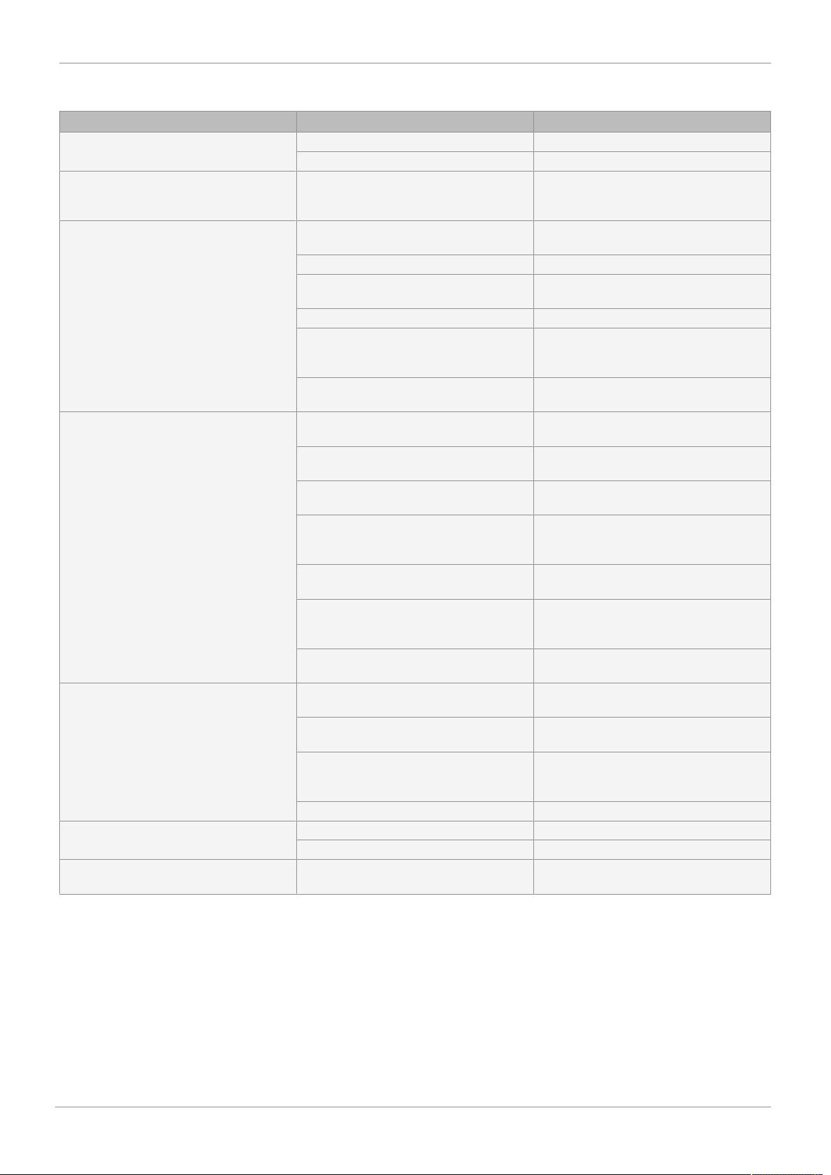
11 Error clearance
11 Error clearance
Error Error cause Error clearance
Control medium escapes from vent hole /
vent in the actuator cover
Working medium escapes from leak
detection hole
The product doesn't open or doesn't
open fully
The product leaks downstream (doesn't
close or doesn't close fully)
The product leaks between actuator and
valve body
Valve body connection to piping leaks Incorrect installation Check installation of valve body in piping
Valve body leaks Valve body leaks or is corroded Check valve body for damage, replace
Piston faulty NC and NO Replace actuator cartridge
Spindle seal leaking NC Replace actuator cartridge
Plug diaphragm faulty Check plug diaphragm for potential
damage, replace plug diaphragm if
necessary
Control pressure too low Operate the product with the control
pressure specified in the datasheet
Pilot valve faulty Replace the pilot valve
Actuator faulty Replace actuator cartridge, replace
actuator if necessary
Control medium not connected Connect the control medium
Plug diaphragm incorrectly mounted Remove actuator, check plug diaphragm
mounting, replace plug diaphragm if
necessary
Actuator spring faulty (for control
function NO)
Operating pressure too high Operate the product with operating
Plug diaphragm incorrectly mounted Remove actuator, check plug diaphragm
Control pressure too low (for control
function NO)
Foreign matter between plug diaphragm
and valve seat
Valve body leaks or is damaged Check valve body for potential damage,
Plug diaphragm faulty Check plug diaphragm for potential
Actuator spring faulty (for control
function NC)
Plug diaphragm incorrectly mounted Remove actuator, check plug diaphragm
Bolting between valve body and actuator
loose
Plug diaphragm faulty Check plug diaphragm for potential
Actuator/valve body damaged Replace actuator/valve body
Sealing material faulty Replace sealing material
Replace actuator cartridge
pressure specified in datasheet
mounting, correct if necessary
Operate valve with control pressure
specified in data sheet
Remove actuator, remove foreign matter,
check plug diaphragm and valve body for
damage and replace if necessary
replace valve body if necessary
damage, replace plug diaphragm if
necessary
Replace actuator cartridge
mounting, correct if necessary
Retighten bolting between valve body
and actuator
damage, replace plug diaphragm if
necessary
valve body if necessary
GEMÜ F40
16 / 24
www.gemu-group.com
Page 17
19
12 Inspection/servicing
12 Inspection/servicing
WARNING
The equipment is subject to pressure!
▶ Risk of severe injury or death.
● Depressurize the plant.
● Completely drain the plant.
CAUTION
Hot plant components!
▶ Risk of burns!
● Only work on plant that has cooled
down.
NOTICE
Exceptional maintenance work!
▶ Damage to the GEMÜ product.
● Any maintenance work and repairs not described in
these operating instructions must not be performed
without consulting the manufacturer first.
The operator must carry out regular visual examination of the
GEMÜ products depending on the operating conditions and
the potential danger in order to prevent leakage and damage.
The product also must be disassembled and checked for
wear in the corresponding intervals.
1. Have servicing and maintenance work performed by
trained personnel.
2. Wear appropriate protective gear as specified in plant operator's guidelines.
3. Shut off plant or plant component.
4. Secure plant or plant component against recommissioning.
5. Depressurize the plant or plant component.
6. Actuate GEMÜ products which are always in the same
position four times a year.
12.1 Replacing the actuator
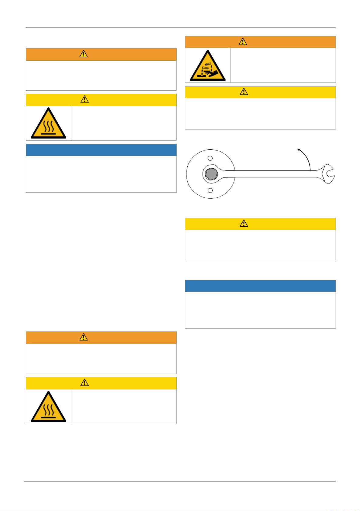
12.1.1 Removing the actuator
WARNING
Corrosive chemicals
▶ Risk of caustic burns
● Wear suitable protective gear.
● Completely drain the plant.
CAUTION
Use of incorrect spare parts!
▶ Damage to the GEMÜ product.
▶ Manufacturer liability and guarantee will be void.
● Use only genuine parts from GEMÜ.
1. Depressurize the air in the actuator.
2. Undo the grub screw in the opening protection.
3. Undo and remove the hex screw by turning it anticlockwise with a WAF19 wrench.
CAUTION
Risk of cartridge falling out
▶ This will damage the cartridge.
● Take care removing the cover, because the cartridge can
come loose in the cover.
4. Remove the cover.
5. Carefully remove the actuator from the valve body.
NOTICE
Important:
▶ After removal, clean all parts of contamination. Take care
not to damage the parts in the process. Afterwards,
check parts for potential damage. If parts are damaged,
replace.
WARNING
The equipment is subject to pressure!
▶ Risk of severe injury or death.
● Depressurize the plant.
● Completely drain the plant.
CAUTION
Hot plant components!
▶ Risk of burns!
● Only work on plant that has cooled
down.
www.gemu-group.com 17 / 24 GEMÜ F40
Page 18
12 Inspection/servicing
19
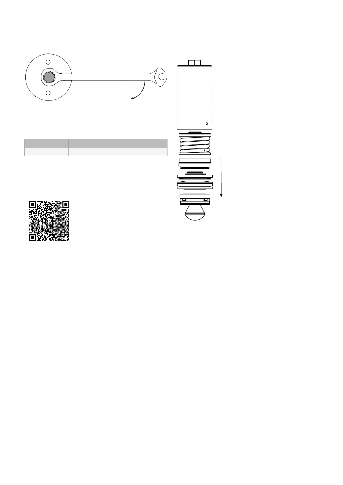
12.1.2 Mounting the actuator
1. Lightly grease the thread on the valve body and actuator.
2. Screw the actuator onto the valve body by turning clockwise (can be positioned at a 90° angle via four-start
thread).
3. Tighten the actuator to the specified torque (see table below).
Actuator size Torque
3 60 Nm
4. Tighten the grub screw in the opening protection.
12.2 Replacing the cartridge
Video showing how to replace the cartridge:
QR code:
12.2.1 Removing the cartridge
1. Remove the actuator from the valve body (see chapter
"Removing the actuator").
Link for Internet browser:
https://www.gemu-group.com/de_DE/videos-und-anima-
tionen/patronenwechsel-fuellventil-gemue-f40
2. Remove the cartridge from the cover or from the valve
body.
3. Clean all parts of contamination. Do not scratch or damage parts during cleaning!
4. Check all parts for potential damage.
5. Replace damaged parts.
www.gemu-group.com18 / 24GEMÜ F40
Page 19
Klick!
12 Inspection/servicing
12.2.2 Mounting the cartridge
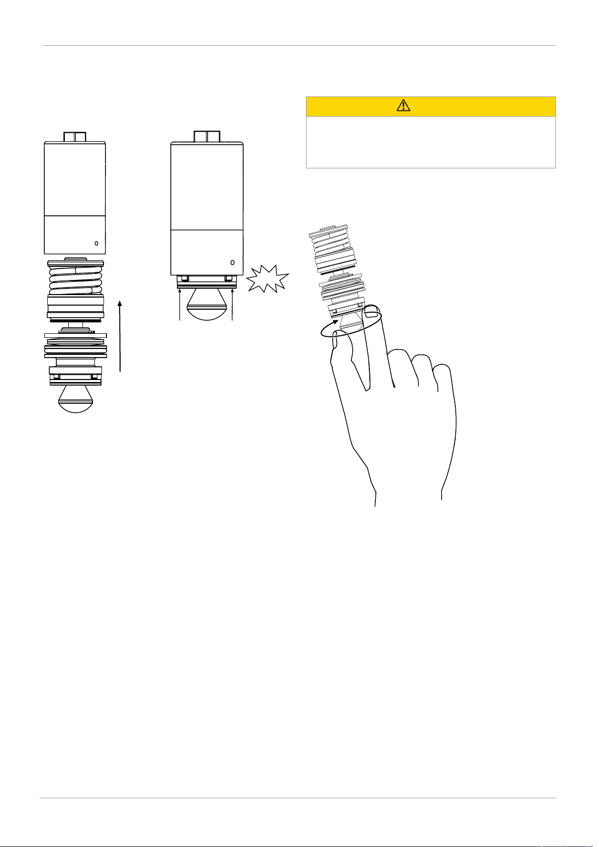
1. Grease the cartridge with a suitable lubricant (e.g. Tunap
Tungrease ST3 grease).
2. Grease the cover with a suitable lubricant (e.g. Tunap
Tungrease ST3 grease).
12.3 Replacing the plug diaphragm
12.3.1 Removing the plug diaphragm
CAUTION
Use of incorrect spare parts!
▶ Damage to the GEMÜ product.
▶ Manufacturer liability and guarantee will be void.
● Use only genuine parts from GEMÜ.
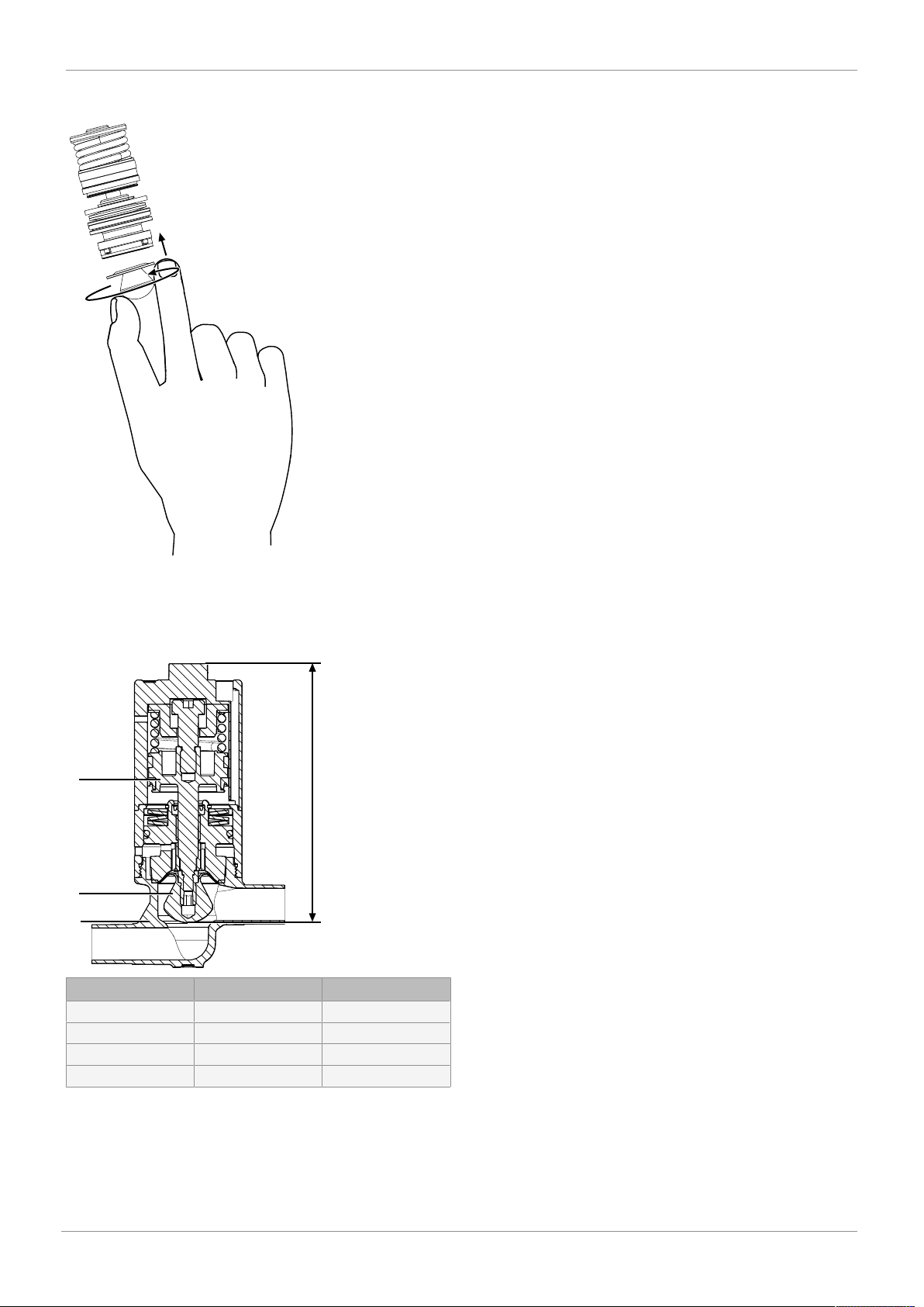
1. Remove the actuator (see chapter "Replacing the actuator").
2. Remove the cartridge (see chapter "Replacing the cartridge").
3. Insert the lubricated cartridge into the cover and press
into the collar of the plug diaphragm until you hear it click
into place.
3. Unscrew the plug diaphragm from the cartridge by hand
by turning it anticlockwise.
4. Clean all parts of contamination. Do not scratch or damage parts during cleaning!
5. Check all parts for potential damage.
6. Replace damaged parts.
www.gemu-group.com 19 / 24 GEMÜ F40
Page 20
13 Removal from piping
A
1
2
3
12.3.2 Mounting the plug diaphragm
1. Screw the plug diaphragm onto the male thread of the
cartridge by turning it clockwise.
2. Ensure the plug diaphragm is hand-tight.
13 Removal from piping
1. Remove the clamp or screw connections in reverse order
to installation.
2. Remove welded or solvent cemented connections using a
suitable cutting tool.
3. Observe the safety information and accident prevention
regulations.
14 Disposal
1. Pay attention to adhered residual material and gas diffusion from penetrated media.
2. Dispose of all parts in accordance with the disposal regulations/environmental protection laws.
15 Returns
Legal regulations for the protection of the environment and
personnel require that the completed and signed return delivery note is included with the dispatch documents. Returned
goods can be processed only when this note is completed. If
no return delivery note is included with the product, GEMÜ
cannot process credits or repair work but will dispose of the
goods at the operator's expense.
1. Clean the product.
2. Request a return delivery note from GEMÜ.
3. Complete the return delivery note.
4. Send the product with a completed return delivery note to
GEMÜ.
12.4 Spare parts
Item Name Order description
A Actuator AF40…
1 Valve body BF00…
2 Plug diaphragm DF00…
3 Cartridge SF40…
www.gemu-group.com20 / 24GEMÜ F40
Page 21
16 Declaration of Incorporation according to 2006/42/EC (Machinery Directive)
16 Declaration of Incorporation according to 2006/42/EC (Machinery Directive)
Declaration of Incorporation
according to the EC Machinery Directive 2006/42/EC, Annex II, 1.B for partly
completed machinery
We, GEMÜ Gebr. Müller Apparatebau GmbH & Co. KG
Fritz-Müller-Straße 6-8
74653 Ingelfingen-Criesbach, Germany
declare that the following product
Make: GEMÜ
Commercial name: GEMÜ F40
meets the following essential requirements of the Machinery Directive 2006/42/EC:
1.1.2, 1.1.3, 1.1.5, 1.3.2, 1.3.3, 1.3.4, 1.5.1, 1.5.2
We also declare that the specific technical documentation has been compiled in accordance with part B of Annex VII.
The manufacturer or his authorised representative undertake to transmit, in response to a reasoned request by the national
authorities, relevant information on the partly completed machinery. This transmission takes place:
Electronically
Authorised documentation officer
This does not affect the industrial property rights!
Important note! The partly completed machinery may be put into service only if it was determined, where appropriate, that the
machinery into which the partly completed machinery is to be installed meets the provisions of this Directive.
GEMÜ Gebr. Müller Apparatebau GmbH & Co. KG
Fritz-Müller-Straße 6-8
74653 Ingelfingen, Germany
Ingelfingen-Criesbach 2019-03-04
Joachim Brien
Head of Technical Department
21 / 24
GEMÜ F40www.gemu-group.com
Page 22

GEMÜ F40
22 / 24
www.gemu-group.com
Page 23

www.gemu-group.com 23 / 24 GEMÜ F40
Page 24
GEMÜ Gebr. Müller Apparatebau GmbH & Co. KG
Fritz-Müller-Straße 6-8, 74653 Ingelfingen-Criesbach,
Germany
Phone +49 (0)7940 123-0 · [email protected]
www.gemu-group.com
Subject to alteration
11.2019 | 88591869
*88591869*
 Loading...